Embed Size (px)
Citation preview
~.------.(~---Vol. 8, NO.4
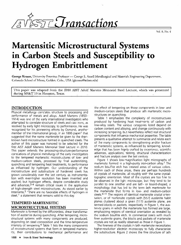
Martensitic Microstructural Systemsin Carbon Steels and Susceptibility toHydrogen EmbrittlementGeorge Krauss, University Emeritus Professor - George S. Ansell Metallurgical and Materials Engineering Department,Colorado School of Mines, Golden, Colo., USA ([email protected])
This paper was adapted from the 2'010 AIST Adolf Martens Memorial Steel Lecture, which was presentedduring MS&T.'lOin Hou~ton, Texas., ' '.. "
INTRODUCTIONPhysical metallurgy correlates structure to processing andperformance of metals and alloys. Adolf Martens (1850-1914) was one of the early international investigators whoattempted to correlate structure of steels and cast irons, asresolved by early light microscopy, to performance. He wasrecognized for his pioneering efforts by Osmond, anothermember of the international group, in an 1895 paper1 thatsuggested that the name martensite be given to the then-known hard microstructure formed in quenched steels.Theauthor of this paper was honored to be selected for thefirst AIST Adolf Martens Memorial Steel Lecture in 2010.This paper extends the processing-structure-performancecorrelations of physical metallurgy of the early investigatorsto the tempered martensitic microstructures of low- andmedium-carbon steels, processed by final austenitizing,quenching and tempering heat treatments, to performanceas influenced by hydrogen. Our understanding of themicrostructure and substructure of hardened steels hasgrown considerably over the last century, as instrumenta-tion with ever-higher resolution has been invented andapplied; but hydrogen effects, despite considerable studyand advances,2-4 remain critical issues in the applicationof high-strength steel microstructures. As stated earlier byInterrante,5 "there are no favorable effects of hydrogen insteel," a statement that remains valid to this day.
TEMPERED MARTENSITICMICROSTRUCTURAL SYSTEMSMartensite is formed by the diffusionless, shear transforma-tion of austenite during quenching. After tempering, micro-structural systems with many components are produced,depending on steel composition and the time-temperatureintensity of tempering6 Table 1 lists the many componentsof microstructural systems that form in tempered martens-ite, their contributions to mechanical performance and
188 • Iron &. Steel Technology
the effect of tempering on those components in low- andmedium-carbon steels that produce lath martensitic micro-structures on quenching.Table 1 emphasizes the complexity of microstructures
produced by hardening heat treatments of- carbon andlow-alloy steels. The various categories listed depend oncarbon content and alloying, and change continuously withincreasing tempering, but nevertheless reflect real structuralcomponents that influence mechanical properties. The tablepresentsa qualitative attempt to summarize and relate eachof the many components to strengthening and/or fractureof martensitic systems, as influenced by tempering, knowl-edge that has been highly crafted by experience, scientificadvances, applications, testing, structural characterizationand fracture analysisover the last century.Figure 1 ~hows low-magnification light micrographs of
martensite formed in a high-purity iron-carbon alloy.? Thesodium bisulfite etch has created areas of various colors.Within each of these areas, there are perhaps hundredsof crystals of martensite, all roughly with the same crystal-lographic orientation. Most of the crystals are too fine tobe observed in the light microscope, but they tend to beparallel to one another and are lath- or board-shaped, amorphology that has led to the term lath martensite forthe martensite that forms in low- and medium-carbonsteels.8-11 The regions of identical martensite crystal orien-tation, or of martensite crystals with {557} austenite habitplanes clustered about a given {111} austenite plane, aretermed blocks or packets, respectively. In Figure 1, the aus-tenite grains in which the martensite has formed are large,emphasizing regions of identical orientation as revealed bythe sodium bisulfite etch. In commercial steels with muchfiner austenite grains, the blocks and packets of martensitecrystalsare not as readily observed as those in Figure 1.The fineness of the crystals in lath martensite necessitates
higher-resolution electron microscopy to fully characterizethe substructure. Figure 2 shows the fine structure of lath
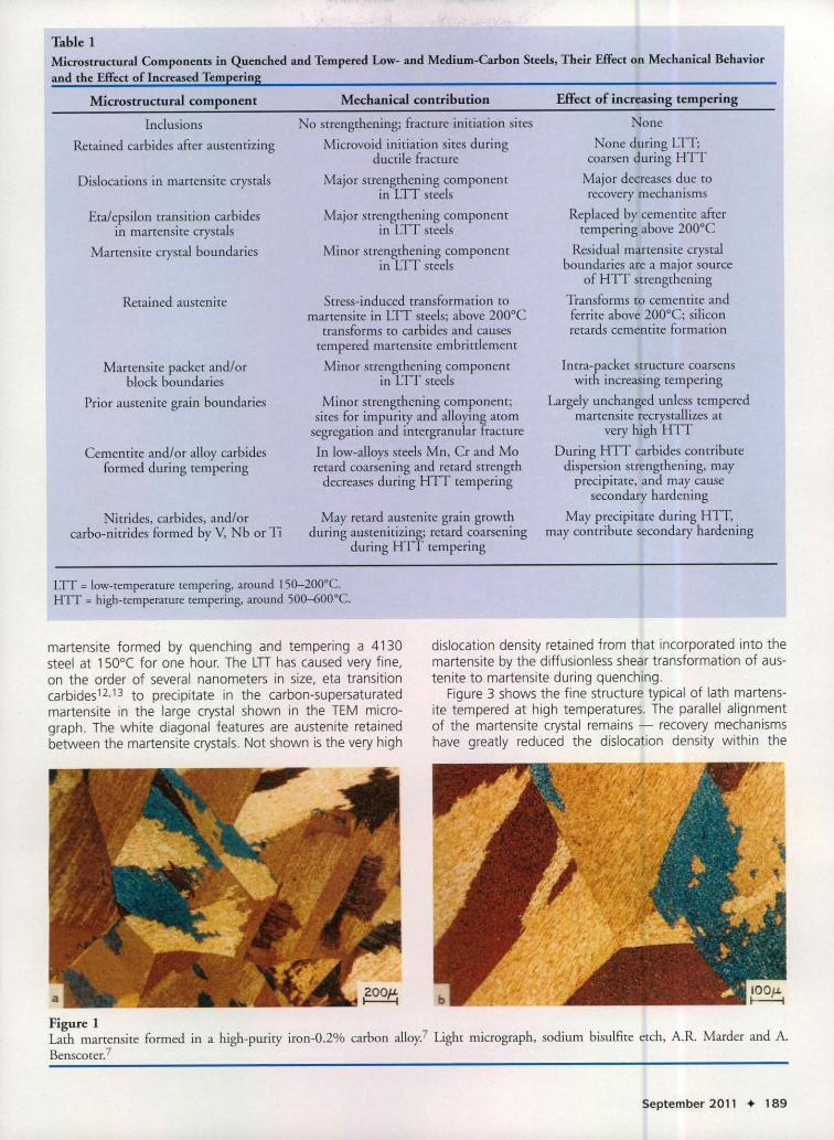
Table 1Microstructural Components in Quenched and Tempered Low- and Medium-Carbon Steels, Their Effect on Mechanical Behaviorand the Effect of Increased Tempering
Microstructural component
InclusionsRetained carbides after austentizing
Dislocations in martensite crystals
Eta/epsilon transition carbidesin martensite crystals
Martensite crystal boundaries
Retained austenite
Martensite packet and/orblock boundaries
Prior austenite grain boundaries
Cementite and/or alloy carbidesformed during tempering
Nitrides, carbides, and/orcarbo-nitrides formed by V, Nb or Ti
Mechanical contribution
No strengthening; fracture initiation sitesMicrovoid initiation sites during
ductile fractureMajor strengthening component
in LTT steelsMajor strengthening component
in LTT steelsMinor strengthening component
in LTT steels
Stress-induced transformation tomartensite in LTT steels; above 200°Ctransforms to carbides and causestempered martensite embrittlementMinor strengthening component
in LTT steelsMinor strengthening component;sites for impurity and alloying atomsegregation and intergranular fractureIn low-alloys steels Mn, Cr and Moretard coarsening and retard strengthdecreases during HTT tempering
May retard austenite grain growthduring austenitizing; retard coarsening
during HTT tempering
Effect of increasing tempering
NoneNone during LTT;coarsen during HTTMajor decreases due torecovery mechanisms
Replaced by cementite aftertempering above 200°CResidual martensite crystal
boundaries are a major sourceof HTT strengthening
Transforms to cementite andferrite above 200°C; siliconretards cementite formation
Intra-packet structure coarsenswith increasing tempering
Largely unchanged unless temperedmartensite recrystallizes at
very high HTTDuring HTT carbides contributedispersion strengthening, mayprecipitate, and may cause
secondary hardeningMay precipitate during HTT,
may contribute secondary hardening
LTT = low-temperaturetempering, around 150-200°C.HTT = high-temperature tempering, around 500-600°C.
martensite formed by quenching and tempering a 4130steel at 1500( for one hour. The LTI has caused very fine,on the order of several nanometers in size, eta transitioncarbides12,13 to precipitate in the carbon-supersaturatedmartensite in the large crystal shown in the TEM micro-graph. The white diagonal features are austenite retainedbetween the martensite crystals. Not shown is the very high
dislocation density retained from that incorporated into themartensite by the diffusionless shear transformation of aus-tenite to martensite during quenching.
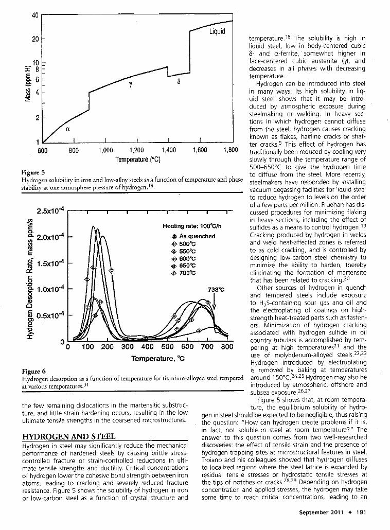
Figure 3 shows the fine structure typical of lath martens-ite tempered at high temperatures. The parallel alignmentof the martensite crystal remains - recovery mechanismshave greatly reduced the dislocation density within the
Figure ILath martensite formed in a high-purity iron-O.2% carbon alloy? Light micrograph, sodium bisulfite etch, A.R. Marder and A.Benscoter?
September 2011 + 189
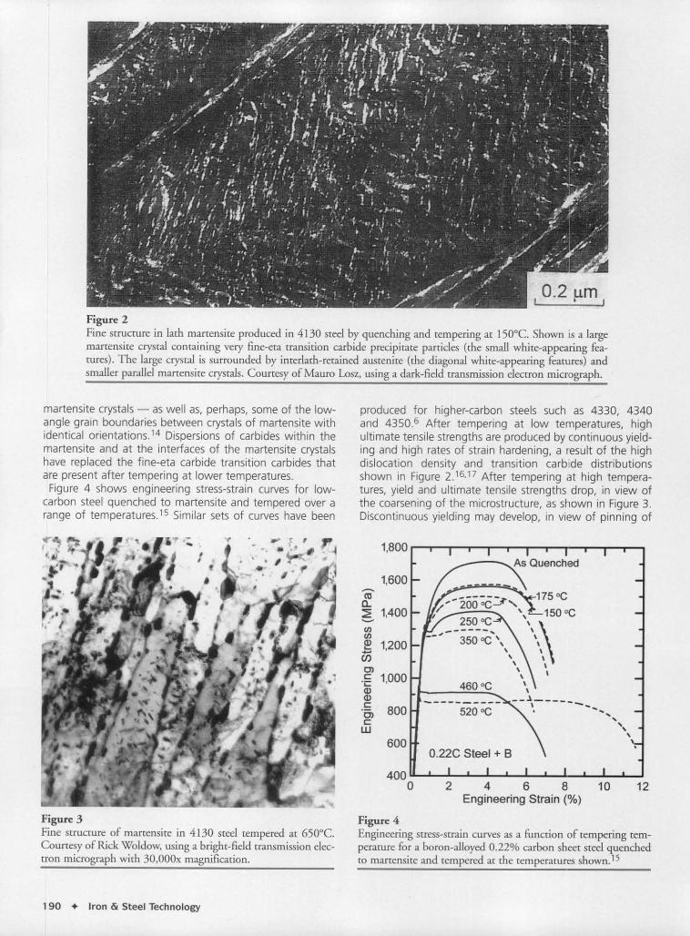
Figure 2Fine structure in lath martensite produced in 4130 steel by quenching and tempering at 150°C. Shown is a largemartensite crystal containing very fine-eta transition carbide precipitate particles (the small white-appearing fea-tures). The large crystal is surrounded by interlath-retained austenite (the diagonal white-appearing features) andsmaller parallel martensite crystals. Courtesy of Mauro Losz, using a dark-field transmission electron micrograph.
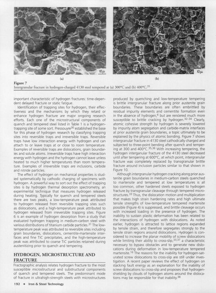
martensite crystals - aswell as, perhaps, some of the low-angle grain boundaries between crystals of martensite withidentical orientations.14 Dispersions of carbides within themartensite and at the interfaces of the martensite crystalshave replaced the fine-eta carbide transition carbides thatare present after tempering at lower temperatures.Figure 4 shows engineering stress-strain curves for low-carbon steel quenched to martensite and tempered over arange of temperatures.15 Similar sets of curves have been
produced for higher-carbon steels such as 4330, 4340and 4350.6 After tempering at low temperatures, highultimate tensile strengths are produced by continuous yield-ing and high rates of strain hardening, a result of the highdislocation density and transition carbide distributionsshown in Figure 2.16•17 After tempering at high tempera-tures, yield and ultimate tensile strengths drop, in view ofthe coarsening of the microstructure, as shown in Figure 3.Discontinuous yielding may develop, in view of pinning of
460°C
2 4 6 8 10 12Engineering Strain (%)
0.22C Steel + 8
------,J 3500C" ,,,,
\\\__________ __.1, _.._
520°C ---, ," ,\.
enenQ) 1,200...-C/)C>c: 1,000.;;::Q)Q)c: BOOC>c:w
600
4000
..•.....coa..~ 1,400--
1,600
1,BOO
Figure 3Fine structure of martensite in 4130 steel tempered at 650°C.Courtesy of Rick Woldow, using a bright-field transmission elec-tron micrograph with 30,000x magnification.
Figure 4Engineering stress-strain curves as a function of tempering tem-perature for a boron-alloyed 0.22% carbon sheet steel quenchedto martensite and tempered at the temperatures shown.IS
190 • Iron & Steel Technology
1,aoo
800
temperature.18 The solubility is high inliquid steel, low in body-centered cubic0- and a-ferrite, somewhat higher inface-centered cubic austenite (y), anddecreases in all phases with decreasingtemperature.
Hydrogen can be introduced into steelin many ways. Its high solubility in liq-uid steel shows that it may be intro-duced by atmospheric exposure duringsteelmaking or welding. In heavy sec-tions in which hydrogen cannot diffusefrom the steel, hydrogen causes crackingknown as flakes, hairline cracks or shat-ter cracks.s This effect of hydrogen hastraditionally been reduced by cooling veryslowly through the temperature range of500-650°C to give the hydrogen timeto diffuse from the steel. More recently,steelmakers have responded by installingvacuum degassing facilities for liquid steelto reduce hydrogen to levelson the orderof a few parts per million. Fruehan has dis-cussed procedures for minimizing flakingin heavy sections, including the effect ofsulfides as a meansto control hydrogen.19
Cracking produced by hydrogen in weldsand weld heat-affected zones is referredto as cold cracking, and is controlled bydesigning low-carbon steel chemistry tominimize the ability to harden, therebyeliminating the formation of martensitethat has been related to cracking.2o
Other sources of hydrogen in quenchand tempered steels include exposureto H2S-containing sour gas and oil andthe electroplating of coatings on high-strength heat-treated parts such asfasten-ers. Minimization of hydrogen crackingassociated with hydrogen sulfide in oilcountry tubulars is accomplished by tem-pering at high temperatures21 and theuse of molybdenum-alloyed steels.22,23
Hydrogen introduced by electroplatingis removed' by baking at temperaturesaround 150°c.24,25 Hydrogen may also beintroduced by atmospheric, offshore andsubsea exposure.26,27
Figure 5 shows that, at room tempera-ture, the equilibrium solubility of hydro-
gen in steel should be expected to be negligible, thus raisingthe question: "How can hydrogen create problems if it is,in fact, not soluble in steel at room temperature?" Theanswer to this question comes from two well-researcheddiscoveries: the effect of tensile strain and the presence ofhydrogen trapping sites at microstructural features in steel.Troiano and his colleagues showed that hydrogen diffusesto localized regions where the steel lattice is expanded byresidual tensile stresses or hydrostatic tensile stresses atthe tips of notches or cracks.28,29 Depending on hydrogenconcentration and applied stresses,the hydrogen may takesome time to reach critical concentrations, leading to an
1,600
Heating rate: 100°C/h
<#> As quenched4} 500°C<S>550°C~ 600°C~ 650°C<t> 700"<;
500 600 700Temperature •••c
300 400
1,000 1,200 1,400Temperature (0C)
100 200
aoo
2.5x10⁻⁴
1600
2
20
~a.~ 2.0x10⁻⁴fJE.sf 1.5x10⁻⁴Clc:oe.. 1.0x10⁻⁴o(/)Q)o~ 0.5x10⁻⁴e-g.:I:
40
the few remaining dislocations in the martensitic substruc-ture, and little strain hardening occurs, resulting in the lowultimate tensile strengths in the coarsened microstructures.
HYDROGEN AND STEELHydrogen in steel may significantly reduce the mechanicalperformance of hardened steels by causing brittle stress-controlled fracture or strain-controlled reductions in ulti-mate tensile strengths and ductility. Critical concentrationsof hydrogen lower the cohesive bond strength between ironatoms, leading to cracking and severely reduced fractureresistance. Figure 5 shows the solubility of hydrogen in ironor low-carbon steel as a function of crystal structure and
Figure 6Hydrogen desorption as a function of temperature for titanium-alloyed steel temperedat various temperatures.31
Figure 5Hydrogen solubility in iron and low-alloy steels as a function of temperature and phasestability at one atmosphere pressure of hydrogen. 18
September 2011 • 191
(a)Figure 7Intergranular fracture in hydrogen-charged 4130 steel tempered at (a) 300°C and (b) 400°c.35
(b)
important characteristic of hydrogen fractures: time-depen-dent delayed fracture or static fatigue.
Identification of trapping sites for hydrogen, their effec-tiveness and the mechanisms by which they retard orenhance hydrogen fracture are major ongoing researchefforts. Each one of the microstructural components ofquench and tempered steel listed in Table 1 is a hydrogen-trapping site of some sort. Pressouyre30 established the basefor this phase of hydrogen research by classifying trappingsites into reversible traps and irreversible traps. Reversibletraps have low interaction energy with hydrogen and canattach to or leave traps at or close to room temperature.Examples of reversible traps are dislocations, grain boundar-ies and solute atoms. Irreversible traps have high interactionenergy with hydrogen and the hydrogen cannot leave unlessheated to much higher temperatures than room tempera-ture. Examples of irreversible traps are inclusions, carbideand nitride particles.
The effect of hydrogen on mechanical properties is stud-ied systematically by cathodic charging of specimens withhydrogen. A powerful way to sort out the effect of trappingsites is by hydrogen thermal desorption spectrometry, anexperimental technique that measures hydrogen releasedduring heating. Typically for quench and tempered steelsthere are two peaks, a low-temperature peak attributedto hydrogen released from reversible trapping sites suchas dislocations, and a high-temperature peak attributed tohydrogen released from irreversible trapping sites. Figure6 is an example of hydrogen desorption from a study thatevaluated hydrogen trapping in medium-carbon steel withvarious distributions of titanium carbide particles.31 The low-temperature peak was attributed to reversible sites includinggrain boundaries, dislocations, cementite-martensite inter-faces and fine TiC precipitates, and the high-temperaturepeak was attributed to coarse TiC particles retained duringaustenitizing prior to quench and tempering.
HYDROGEN, MICROSTRUCTURE ANDFRACTUREFractographic analysis relates hydrogen fracture to the mostsusceptible microstructural and substructural componentsof quench and tempered steels. The predominant modeof fracture in ultrahigh-strength steels with microstructures
192 • Iron &. Steel Technology
produced by quenching and low-temperature temperingis brittle intergranular fracture along prior austenite grainboundaries. These boundaries are often embrittled byresidual impurity elements and cementite formation evenin the absence of hydrogen,6 but are rendered much moresusceptible to brittle cracking by hydrogen.32-34 Clearly,atomic cohesive strength by hydrogen is severely loweredby impurity atom segregation and carbide ..matrix interfacesat prior austenite grain boundaries, a topic ultimately to beexplained by the physics of atomic bonding. Figure 7 showsintergranular fracture in 4130 steel cathodically charged andsubjected to three-point bending after quench and temper-ing at 300 and 400°c.35,36 With increasing tempering, thehydrogen interganular fracture of the 4130 steel decreaseduntil after tempering at 600°(, at which point, intergranularfracture was completely replaced by transgranular brittlefracture around inclusion particles similar to that shown inFigure 10.
Although intergranular hydrogen cracking along prior aus-tenite grain boundaries in medium-carbon steels quenchedto martensite and tempered at low temperatures is alltoo common, other hardened steels exposed to hydrogenfracture by transgranular cleavage through tempered micro-structures.33 Thus, the dislocation motion and multiplicationthat makes high strain hardening rates and high ultimatetensile strengths of low-temperature tempered martensitepossible (Figure 4) is suppressed, and brittle cleavage occurswith increased loading in the presence of hydrogen. Theinability to sustain plastic deformation has been related tothe interactions of hydrogen with dislocations. As notedearlier, hydrogen is attracted to lattice rE?gions expandedby tensile strain, and therefore segregates strongly to thetensile strain regions around dislocations. Hydrogen is con-sidered to increase the planar mobility of screw dislocationswhile limiting their ability to cross-slip,33,37 a characteristicnecessary to bypass obstacles and to generate new dislo-cations during deformation in low-temperature temperedmartensite.16 The reasons for the inability for hydrogen-sat-urated screw dislocations to cross-slip are still under inves-tigation. A recent paper reviews the effect of hydrogen onstacking fault energy as an explanation for the inability ofscrew dislocations to cross-slip and proposes that hydrogen-shielding by clouds of hydrogen atoms around the disloca-tions may be responsible for that inability.38
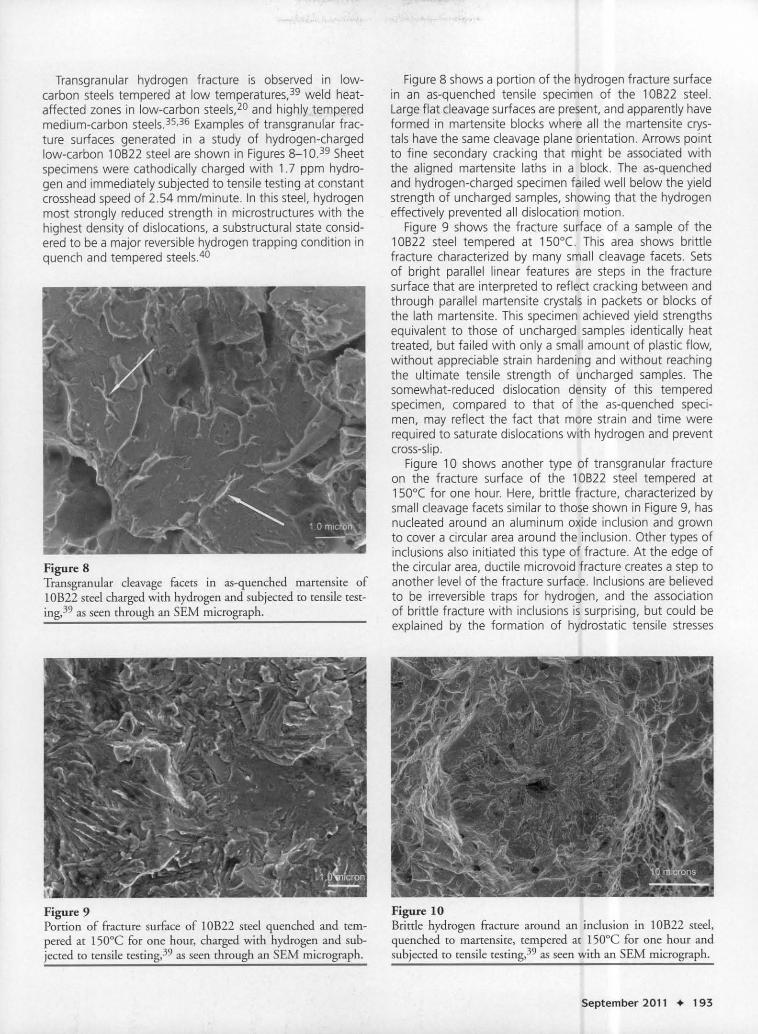
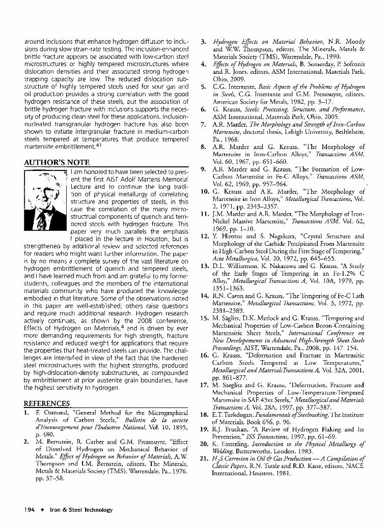
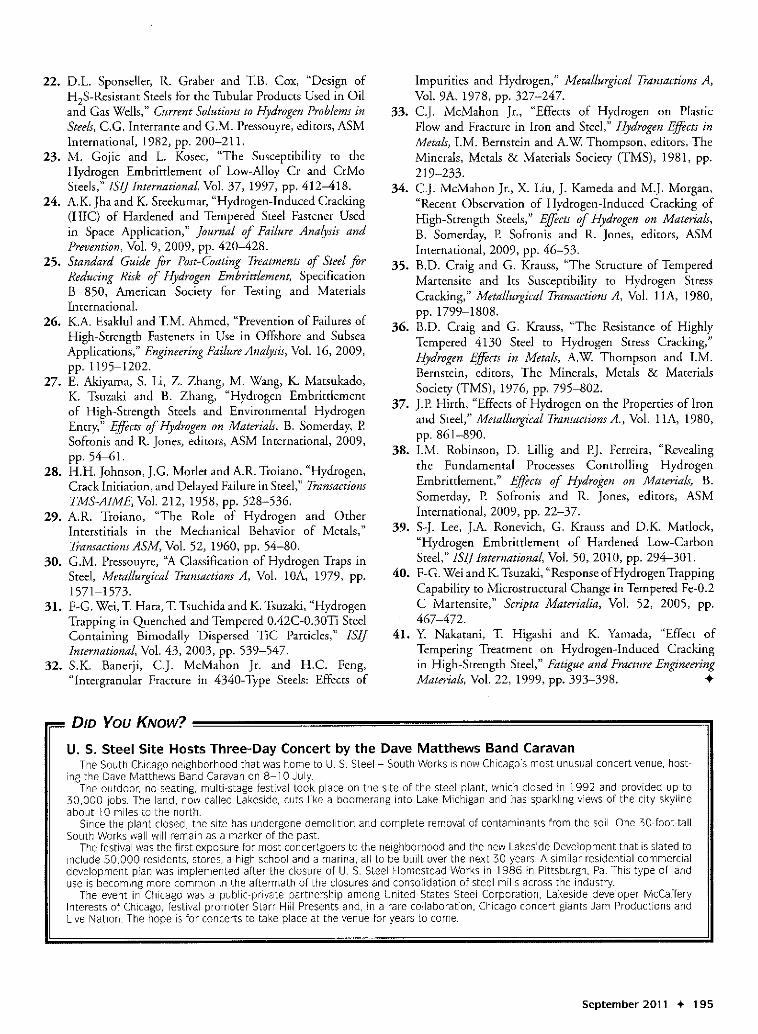
Transgranular hydrogen fracture is observed in low-carbon steels tempered at low temperatures,39 weld heat-affected zones in low-carbon steels,20 and highly temperedmedium-carbon steels.35.36 Examples of transgranular frac-ture surfaces generated in a study of hydrogen-chargedlow-carbon 10822 steel are shown in Figures 8-10.39 Sheetspecimens were cathodically charged with 1.7 ppm hydro-gen and immediately subjected to tensile testing at constantcross head speed of 2.54 mm/minute. In this steel, hydrogenmost strongly reduced strength in microstructures with thehighest density of dislocations, a substructural state consid-ered to be a major reversible hydrogen trapping condition inquench and tempered steels.4o
Figure 8Transgranular cleavage facers in as-quenched martensite of10B22 steel charged with hydrogen and subjected to tensile test-ing,39 as seen through an SEM micrograph.
Figure 9Portion of fracture surface of 10B22 steel quenched and tem-pered at 150aC for one hour, charged with hydrogen and sub-jected to tensile testing,39 as seen through an SEM micrograph.
Figure 8 shows a portion of the hydrogen fracture surfacein an as-quenched tensile specimen of the 10822 steel.Large flat cleavage surfaces are present, and apparently haveformed in martensite blocks where all the martensite crys-tals have the same cleavage plane orientation. Arrows pointto fine secondary cracking that might be associated withthe aligned martensite laths in a block. The as-quenchedand hydrogen-charged specimen failed well below the yieldstrength of uncharged samples, showing that the hydrogeneffectively prevented all dislocation motion.
Figure 9 shows the fracture surface of a sample of the10822 steel tempered at 150°C. This area shows brittlefracture characterized by many small cleavage facets. Setsof bright parallel linear features are steps in the fracturesurface that are interpreted to reflect cracking between andthrough parallel martensite crystals in packets or blocks ofthe lath martensite. This specimen achieved yield strengthsequivalent to those of uncharged samples identically heattreated, but failed with only a small amount of plastic flow,without appreciable strain hardening and without reachingthe ultimate tensile strength of uncharged samples. Thesomewhat-reduced dislocation density of this temperedspecimen, compared to that of the as-quenched speci-men, may reflect the fact that more strain and time wererequired to saturate dislocations with hydrogen and preventcross-slip.
Figure 10 shows another type of transgranular fractureon the fracture surface of the 10822 steel tempered at1500( for one hour. Here, brittle fracture, characterized bysmall cleavage facets similar to those shown in Figure 9, hasnucleated around an aluminum oxide inclusion and grownto cover a circular area around the inclusion. Other types ofinclusions also initiated this type of fracture. At the edge ofthe circular area, ductile microvoid fracture creates a step toanother level of the fracture surface. Inclusions are believedto be irreversible traps for hydrogen, and the associationof brittle fracture with inclusions is surprising, but could beexplained by the formation of hydrostatic tensile stresses
Figure 10Brittle hydrogen fracture around an inclusion in 10B22 steel,quenched to martensite, tempered at 150aC for one hour andsubjected to tensile testing,39 as seen with an SEM micrograph.
September 2011 • 193
around inclusions that enhance hydrogen diffusion to inclu-sions during slow strain-rate testing. The inclusion-enhancedbrittle fracture appears be associatedwith low-carbon steelmicrostructures or highly tempered microstructures wheredislocation densities and their associated strong hydrogentrapping capacity are low. The reduced dislocation sub-structure of highly tempered steels used for sour gas andoil production provides a strong correlation with the goodhydrogen resistance of these steels, but the association ofbrittle hydrogen fracture with inclusions supports the neces-sity of producing clean steel for these applications. Inclusion-nucleated transgranular hydrogen fracture has also beenshown to initiate intergranular fracture in medium-carbonsteels tempered at temperatures that produce temperedmartensite embrittlement.41
AUTHOR'S NOTEI am honored to have been selectedto pres-ent the first AISTAdolf Martens MemorialLecture and to continue the long tradi-tion of physical metallurgy of correlatingstructure and properties of steels, in thiscase the correlation of the many micro-structrual components of quench and tem-pered steels with hydrogen fracture. Thispaper very much parallels the emphasisI placed in the lecture in Houston, but is
strengthened by additional review and selected referencesfor readerswho might want further information. The paperis by no means a complete survey of the vast literature onhydrogen embrittlement of quench and tempered steels,and I have learned much from and am grateful to my formerstudents, colleagues and the members of the internationalmaterials community who have produced the knowledgeembodied in that literature. Someof the observations notedin this paper are well-established; others raise questionsand require much additional research. Hydrogen researchactively continues, as shown by the 2008 conference,Effects of Hydrogen on Materials,4 and is driven by evermore demanding requirements for high strength, fractureresistance and reduced weight for applications that requirethe properties that heat-treated steelscan provide. The chal-lenges are intensified in view of the fact that the hardenedsteel microstructures with the highest strengths, producedby high-dislocation-density substructures, as compoundedby embrittlement at prior austenite grain boundaries, havethe highest sensitivity to hydrogen.
REFERENCES1. F. Osmond, "General Method for the Micrographical
Analysis of Carbon Steels," Bulletin de la societed'Encouragement pour I1ndustrie National Vol. 10, 1895,p.480.
2. M. Bernstein, R. Garber and G.M. Pressouyre, "Effectof Dissolved Hydrogen on Mechanical Behavior ofMetals," Effect of Hydrogen on Behavior of Materials, A.WThompson and I.M. Bernstein, editors, The Minerals,Metals & Materials Society (TMS), Warrendale, Pa., 1976,pp.37-58.
194 •. Iron & Steel Technology
3. Hydrogen Effects on Material Behavior, N.R. Moodyand WW Thompson, editors, The Minerals, Metals &Materials Society (TMS), Warrendale, Pa., 1990.
4. Effects of Hydrogen on Materials, B. Somerday, P. Sofronisand R. Jones, editors, ASM International, Materials Park,Ohio, 2009.
5. e.G. Interrante, Basic Aspects of the Problems of Hydrogenin Steels, e.G. Interrante and G.M. Pressouyre, editors,American Society for Metals, 1982, pp. 3-17.
6. G. Krauss, Steels: Processing, Structure, and PerfOrmance,ASM International, Materials Park, Ohio, 2005.
7. A.R. Marder, The Morphology and Strength of Iron-CarbonMartensite, doctoral thesis, Lehigh University, Bethlehem,Pa., 1968.
8. A.R. Marder and G. Krauss, "The Morphology ofMartensite in Iron-Carbon Alloys," Transactions ASM,Vol. 60,1967, pp. 651-660.
9. A.R. Marder and G. Krauss, "The Formation of Low-Carbon Martensite in Fe-C Alloys," Transactions ASM,Vol. 62, 1969, pp. 957-964.
10. G. Krauss and A.R. Marder, "The Morphology ofMartensite in Iron Alloys," Metallurgical Transactions, Vol.2, 1971, pp. 2343-2357.
11. J.M. Marder and A.R Marder, "The Morphology ofIron-Nickel Massive Martensite," Transactions ASM, Vol. 62,1969, pp. 1-10.
12. Y. Hirotsu and S. Nagakura, "Crystal Structure andMorphology of the Carbide Precipitated From Martensitein High-Carbon Steel During the First Stage ofTempering,"Acta Metallurgica, Vol. 20, 1972, pp. 645-655.
13. D.L. Williamson, K. Nakazawa and G. Krauss, ''A Studyof the Early Stages of Tempering in an Fe-1.2% CAlloy," Metallurgical Transactions A, Vol. lOA, 1979, pp.1351-1363.
14. R.N. Caron and G. Krauss, "The Tempering of Fe-C LathMartensite," Metallurgical Transactions, Vol. 3, 1972, pp.2381-2389.
15. M. Saglitz, D.K. Matlock and G. Krauss, "Tempering andMechanical Properties of Low-Carbon Boron-ContainingMartensitic Sheet Steels," International Conftrence onNew Developements in Advanced High-Strength Sheet SteelsProceedings, AIST, Warrendale, Pa., 2008, pp. 147-154.
16. G. Krauss, "Deformation and Fracture in MartensiticCarbon Steels Tempered at Low Temperatures,"Metallurgical and Materials Transactions A, Vol. 32A, 2001,pp. 861-877.
17. M. Saeglitz and G. Krauss, "Deformation, Fracture andMechanical Properties of Low-Temperature-TemperedMartensite in SAE43xx Steels,"Metallurgical and MaterialsTransactions A, Vol. 28A, 1997, pp. 377-387.
18. E.T. Turkdogan, Fundamentals of Steelmaking, The Instituteof Materials, Book 656, p. 96.
19. R.J. Fruehan, ''A Review of Hydrogen Flaking and ItsPrevention," ISS Transactions, 1997, pp. 61-69.
20. K. Easterling, Introduction to the Physical Metallurgy ofWelding, Butterworths, London, 1983.
21. H~ Corrosion in Oil & Gas Production - A Compilation ofClassic Papers, RN. Tuttle and RD. Kane, editors, NACEInternational, Houston, 1981.
22. D.L. Sponseller, R. Graber and TB. Cox, "Design ofH2S-Resistant Steels for the Tubular Products Used in Oiland Gas Wells," Current Solutions to Hydrogen Problems inSteels,e.G. Interrante and G.M. Pressouyre, editors, ASMInternational, 1982, pp. 200-21l.
23. M. Gojic and L. Kosec, "The Susceptibility to theHydrogen Embrittlement of Low-Alloy Cr and CrMoSteels," ISIJ International, Vol. 37,1997, pp. 412-418.
24. AK. Jha and K. Sreekumar, "Hydrogen-Induced Cracking(HIC) of Hardened and Tempered Steel Fastener Usedin Space Application," Journal of Failure Analysis andPrevention, Vol. 9, 2009, pp. 420-428.
25. Standard Guide for Post-Coating Treatments of Steel forReducing Risk of Hydrogen Embrittlement, SpecificationB 850, American Society for Testing and MaterialsInternational.
26. K.A Esaklul and TM. Ahmed, "Prevention of Failures ofHigh-Strength Fasteners in Use in Offshore and SubseaApplications," Engineering FailureAnalysis, Vol. 16,2009,pp. 1195-1202.
27. E. Akiyama, S. Li, Z. Zhang, M. Wang, K. Matsukado,K. Tsuzaki and B. Zhang, "Hydrogen Embrittlementof High-Strength Steels and Environmental HydrogenEntry," Effects of Hydrogen on Materials, B. Somerday, P.Sofronis and R. Jones, editors, ASM International, 2009,pp.54-61.
28. H.H. Johnson, J.G. Morlet and AR. Troiano, "Hydrogen,Crack Initiation, and Delayed Failure in Steel," TransactionsTMS-AIME, Vol. 212, 1958, pp. 528-536.
29. A.R. Troiano, "The Role of Hydrogen and OtherInterstitials in the Mechanical Behavior of Metals,"TransactionsASM, Vol. 52, 1960, pp. 54-80.
30. G.M. Pressouyre, ''A Classification of Hydrogen Traps inSteel, Metallurgical TransactionsA, Vol. lOA, 1979, pp.1571-1573.
31. F-G. Wei, T Hara, T Tsuchida and K. Tsuzaki, "HydrogenTrapping in Quenched and Tempered 0.42C-0.30Ti SteelContaining Bimodally Dispersed TiC Particles," lSI]International, Vol. 43, 2003, pp. 539-547.
32. S.K. Banerji, e.]. McMahon Jr. and H.e. Feng,"Intergranular Fracture in 4340-Type Steels: Effects of
Impurities and Hydrogen," Metallurgical TransactionsA,Vol. 9A, 1978, pp. 327-247.
33. e.J. McMahon Jr., "Effects of Hydrogen on PlasricFlow and Fracture in Iron and Steel," Hydrogen Effects inMetals, LM. Bernstein and AW Thompson, editors, TheMinerals, Metals & Materials Society (TMS), 1981, pp.219-233.
34. e.J. McMahon Jr., X. Liu, J. Kameda and M.J. Morgan,"Recent Observation of Hydrogen-Induced Cracking ofHigh-Strength Steels," Effects of Hydrogen on Materials,B. Somerday, P. Sofronis and R. Jones, editors, ASMInternational, 2009, pp. 46-53.
35. B.D. Craig and G. Krauss, "The Structure of TemperedMartensite and Its Susceptibility to Hydrogen StressCracking," Metallurgical TransactionsA, Vol. 11A, 1980,pp. 1799-1808.
36. B.D. Craig and G. Krauss, "The Resistance of HighlyTempered 4130 Steel to Hydrogen Stress Cracking,"Hydrogen Effects in Metals, A.W Thompson and LM.Bernstein, editors, The Minerals, Metals & MaterialsSociety (TMS), 1976, pp. 795-802.
37. ].P. Hirth, "Effects of Hydrogen on the Properties offronand Steel," Metallurgical TransactionsA., Vol. llA, 1980,pp. 861-890.
38. LM. Robinson, D. Lillig and P.J. Ferreira, "Revealingthe Fundamental Processes Controlling HydrogenEmbrittlement," Effects of Hydrogen on Materials, B.Somerday, P. Sofronis and R. Jones, editors, ASMInternational, 2009, pp. 22-37.
39. S-]. Lee, J.A. Ronevich, G. Krauss and D.K. Matlock,"Hydrogen Embrittlement of Hardened Low-CarbonSteel," lSI] International, Vol. 50,2010, pp. 294-30l.
40. F-G. Wei and K. Tsuzaki, "Response of Hydrogen TrappingCapability to Microstructural Change in Tempered Fe-0.2C Martensite," Scripta Materialia, Vol. 52, 2005, pp.467-472.
41. Y. Nakatani, T Higashi and K. Yamada, "Effect ofTempering Treatment on Hydrogen-Induced Crackingin High-Strength Steel," Fatigue and Fracture EngineeringMaterials, Vol. 22, 1999, pp. 393-398. •
U. S. Steel Site Hosts Three-Day Concert by the Dave Matthews Band CaravanThe South Chicago neighborhood that was home to U. S. Steel - South Works is now Chicago's most unusual concert venue, host-
ing the Dave Matthews Band Caravan on 8-10 July.The outdoor, no-seating, multi-stage festival took place on the site of the steel plant, which closed in 1992 and provided up to
30,000 jobs. The land, now called Lakeside, cuts like a boomerang into Lake Michigan and has sparkling views of the city skylineabout 10 miles to the north.
Since the plant closed, the site has undergone demolition and complete removal of contaminants from the soil. One 30-foot-tallSouth Works wall will remain as a marker of the past.
The festival was the first exposure for most concertgoers to the neighborhood and the new Lakeside Development that is slated toinclude 50,000 residents, stores, a high school and a marina, all to be built over the next 30 years. A similar residential-commercialdevelopment plan was implemented after the closure of U. S. Steel Homestead Works in 1986 in Pittsburgh, Pa This type of landuse is becoming more common in the aftermath of the closures and consolidation of steel mills across the industry.
The event in Chicago was a public-private partnership among United States Steel Corporation, Lakeside developer McCafferyInterests of Chicago, festival promoter Starr Hill Presents and, in a rare collaboration, Chicago concert giants Jam Productions andLive Nation. The hope is for concerts to take place at the venue for years to come.
September 2011 + 195