Embed Size (px)
Citation preview

4000k, a luminaire
MARTIN PAULSSON bachelor degree project

4000k, a luminaireMartin Paulsson
Degree Project for Bachelor of Fine Arts in DesignMain field of study Industrial Design, ErgonomicsFrom Lund University School of Industrial Design, Department of Design Sciences
Examiner: Professor Claus-Christian EckhardtSupervisors: Professor Claus-Christian Eckhardt, Lecturer Anna Persson, Senior Lecturer Jasjit Singh, Senior Lecturer Charlotte Sjödell
Other Contributers: CEO Jelmtech Carl-Fredrik Emilsson, Painter Tommy Alm, Professor Torbjörn Lajke, vice University lektor Hillevi Hempelä
2019
ISRN: LUT-DVIDE/ EX--19/50460-SE
ABSTRACT There are great risks of a multi-tude of injuries due to poor
light at construction sites. This leads ultimately to costly counteractions from society. The goal of this project was to put construction workers’ situation in the spotlight by giving construction sites better vision ergo-nomics through providing enough, even and glare-free light. With the GARO Ball luminaire as benchmark I designed a luminaire with hooks and loops out of steel wire and a shape which asks the builder to model
the light according to needs. To dim the light there is new technology in other fields which enables an easy way to smart construction
sight lighting. Better placements of the luminaire and the possibility to dim the light created better vision conditions
at indoor construction sites. The project involved exter-nal expertise and guidance as well as interviews and
user tests. The result was measured in an ex-periment which proved it to reduce
contrasts in the environment up to three times compa-
red with the GARO Ball.
Sammanfattning:
Det finns stora risker för en mängd olyckor på grund av dålig belysning på byggarbetsplatser. Den vanligaste typen av byggbelysning är inte anpassad för sekundära användningsområden vilket orsakar bländning och långsamt arbetsflöde. Genom att undersöka ljusets spridning kunde jag designa en belysningsarmatur som effektivt sprider ljuset upp i taket och på så sätt ska-par ett bra allmänljus. Formen möjliggör nya sätt att placera byggbelysning på arbetsplatsen och omöjliggör belysningens minst gynnsamma placering, upprätt på golvet.

PROBLEM
ACKNOWLEDGEMENTS
10-13
6-7
16-19
22-31
36-49
50-53
DESIGN CONSIDERATIONS
PROCESS
4000K, A LUMINAIRE
EVALUATION
Special thanks to my family who supported this work. both my partner Emma and our son Alvar made their best
in supporting me. They did everythng from occationally following me to school to taking care of each other and our
fourth family member: The Luminaire.
Content

6 7
This project originated in a product specification handed to me by the CEO of Jelmtech Carl-Fredrik Emilsson.
The product in question was the nearly 10 years old GARO Ball luminaire. The project was continued as if GARO would hire me to design a future version of their bestselling light fixture.
Supervision was kindly given to me by Carl-Fredrik Emils-son at Jelmtech, Hillevi Hemphälä and Torbjörn Laike at Lund University. Charlotte Sjödell was main supervisor and the project culminated in an opportunity to get feedback from Magnus Scott and Niclas Alldén, the CEO and the sales manager of GARO in a post project meeting.
Special thanks to Tommy Alm at AP måleri who tested my product and whom I interviewed. This gave me the input needed to get the project straightened out.
Per Merke at LU-innovation helped me to get a European design protection of the final design so I could show my luminaire more freely.
acknow-ledgements
Opposite page: GARO Ball luminaire

8 9

10 11
-What’s lost in bad lightDuring a time-study of the work performed when rough plas-tering walls in a normal sized bedroom the light was moved and adapted 12 times (2). Better light was required to conti-nue the work but moving the light resulted in loss of time.
What is good working light and good vision conditions? The answer will depend on factors such as age, vision impair-ments, time of the day and specific working tasks. Experts in ergonomics (5,6) claim that good working light has three key ingredients, enough light, even light without sharp shadows or contrasts and absence of glare.
Poor working light can result in headache, dry and sore eyes as well as short- or long-term vision impairments (2). 2017 where 25% of all construction site accidents in Sweden due to tripping or falling (4). In these cases, construction workers fell so badly the consequences where worth mentioning to insurance companies etc. It’s sure that at least a few of these accidents where avoidable in better vision conditions. In poor light workers are less lightly to use safety equipment such as goggles as they further reduce the ability to see (2). This poses a direct threat to the eyes of the workers which in worst case leaves them blind for lifetime.
Problem
VISION ERGONOMY RESEAR-CH, 1992
”74% of the workers ra-ted the build sight ligh-ting to be bad or very
bad”
VISION ERGONOMY EXPERT, 2019
”What exists today should be altered so it creates more light from a greater nubmer of light
fixtures which individually should be less powerful ”
VISION ERGONOMY RESEARCH, 1986/87
”great risk of getting blinded by spotlights.”
BYGGNADS, 2018
”25% of all build sight accidents are results of
tripping or falling”
When workers work slower and take sick-leaves due to headache or injuries inflicted at work it is not only a perso-nal problem as they lose income but for the entire society in terms of allowances.
-The LuminairesThe luminaires which are meant to provide construction sites with common lighting are hung in rows, five to seven meters apart. At larger build sites they are connected to 42-volt loops driven by power units placed in the staircase at every floor. They generally produce powerful light at between 1500 and 2500 lumen. The cylindrical dome spreads the light both towards the walls, the floor and the ceiling. This light is good enough to perform simpler tasks but not enough for some work. To be able to read measurements or paint (together with many other tasks) additional light must be fitted, so called spotlighting (2).
To provide spotlight at work sites there are special luminaires of monitor type with a relatively large emittive area compared with the power of the light (2). At every spot where a worker performs a critical task such as painting there should be at least two of these luminaires added (to remove sharp sha-dows). They are considered to be large and bulky and instead, the cheap, low weight and therefore handy common light luminaires (which are designed to hang in the ceiling) stands in as extra light. They have been slightly adapted to fit on top of tripods, but instead the tripods are considered to be heavy
and unpractical. Often, they are placed directly on the floor as their shape affords this placement over any other. This is in fact the way builders, painters and mortars are using them every day. However, in this way the construction workers are being blinded by the intense light. So, why are they not betted adapted to provide extra light? The answer being, they were not meant to be providers of extra light and the factories make their money by the sales of luminaires to large build sites (or rather tool rentals) not the actual users. If these luminaires are used as spotlights, they should be better suited for it. The term Universal Design could be adapted to help all workers with their vision both at the small and the larger build sites.
-System BackgroundIn the 80’s the construction site lighting consisted of bare light bulbs hung from E27 sockets in the ceiling. On the floor, builders generally placed high luminescent luminaires of spotlight type (3). This primitive system called for impro-vements. The common light luminaires where introduced with two power outlets to drive spot lighting of a new and improved monitor type (2). These are only improvements of the system and not the ultimate solution for work light. As ergonomics expert Hillevi Hemphälä at Lund University puts it; -there should be more light fixtures and of lower intensity than today because the environment is too unevenly lit (6).

12
Some of the luminaires on the market
-Construction cultureLuminaires and other tools used at work sites are general-ly bashed about and not very well taken care of (7). There appears to be an existing lack of respect towards things in general at construction sites. When the luminaires are being removed from the sites they are thrown into pallets for trans-port and storage, sometimes outside. So, the construction industry calls for a product which is very durable, simple to maintain and cheap to purchase (7).
Other interest in these luminaires come from manufacturers who earns money selling their products but also sell goodwill and their brand. These stakeholders of course want good rela-tionships with the customers. Also, the workers who work in the factories want a healthy work environment which means it is important to choose a suiting production technique and location.
All parts involved after the production stage of the lifecycle wants a product which is safe to use and works well. A pro-blem as I see it, is that all stakeholders except the actual user of the product have the same idea of the term “works”. At pre-sent most of the production, retail and usage of the construc-tion site lighting is focused to meet standards and regula-tions. The problem in this case is that the tangible standards regulate only amounts of light not how it is being emitted (1).
Therefore, the industry makes luminaires producing enough power to be hung in the ceiling at seven meters intervals. No float-luminaire I found on the market provides the user with the possibility of diming the light to suite smaller work sites or secondary usages.
In the process of designing and making work site luminaires there should, prior to anything else, be a thorough evaluation of what the builders need of in terms of light and other featu-res. Only then can the users needs be truly well met.
-Tommy Alm, a painterA few weeks into the project I visited a painter at his working site. This trip occurred quite spontaneously but came to open my eyes to the problem which I later addressed. To include the painter, Tommy Alm and workers like him was to be the main target for my work.
This particular day Tommy worked in a kitchen, as many other small and middle-sized companies which provides build services, he often changed working site. Typically, once every couple of days he must pack all his things together and store them in his van. To be able to carry and store the equipment is important as he otherwise wouldn’t bring it.
He worked in both new buildings without fitted common light and in old ones where existing light fixtures provide the
Right: GARO Ball luminaire in use. Note; photographer used the flash to get enough light
13
Below: Tommy Alm, a painter. Here is bending away fom the light to reach his pocket. Picture taken in a kitchen
where he worked.
environment with light. To increase the levels of illumination enough to be able to paint he brought with him a GARO ball luminaire. As we walked into the kitchen the first thing, he did was to plug it in. We were both severely blinded as it was placed on a stool/ladder in the centre of the kitchen. It produced 2000 plus lumen in an otherwise quite badly lit up environment. In this light he was to work an entire working day.
-Market researchThe market research was limited to the internet. When designing something it might be important to see what’s on the market. However, my research was focused more on the problem itself and what luminaire should really look like. Off course when it’s been constraint by the stakeholders and the derived functions. In fact, the market research was not done initially but rather later in the project to see if someone had derived similar conclusions.
14 15
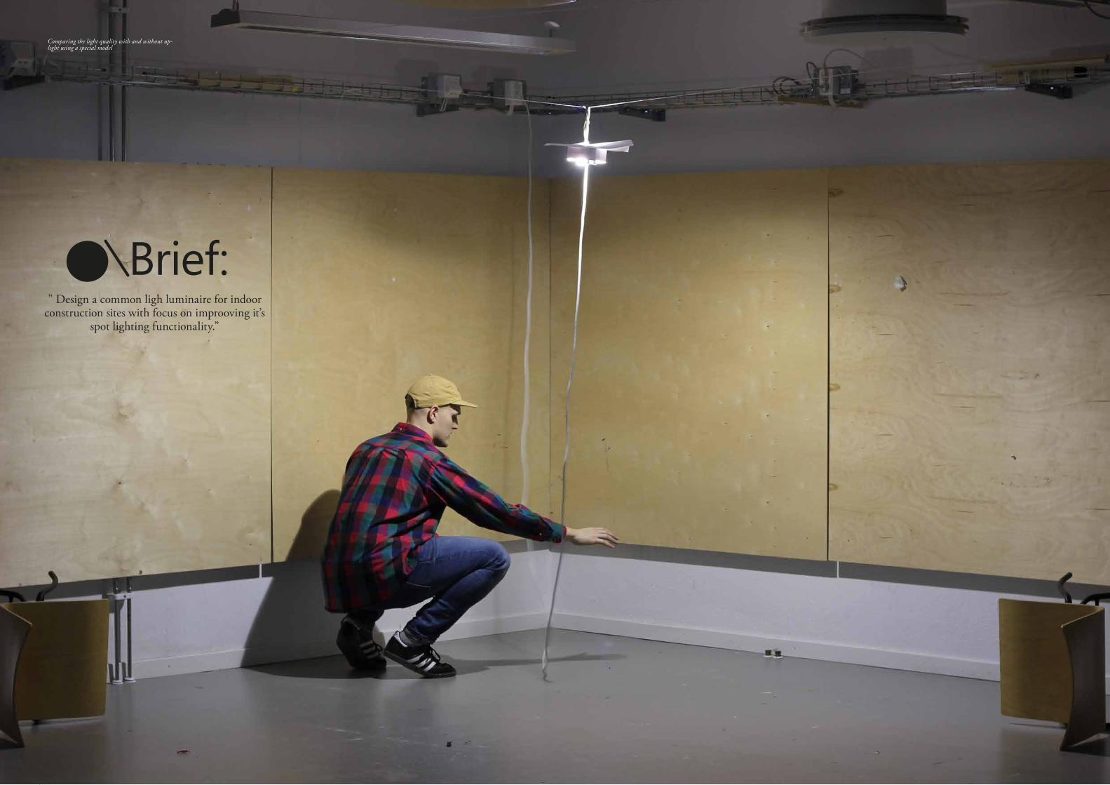
Comparing the light quality with and without up-light using a special model
Brief:” Design a common ligh luminaire for indoor
construction sites with focus on improoving it’s spot lighting functionality.”

16 17
200?LED REPLACES THE LIGHT BULB AND LOW ENERGY E27
-Smart light at siteOne of the main problems with the working light on the market is the lack of adjusting or diming the light intensity. As these features have moved into the interiors of most homes a lot of people has started to understand the importance of being able to adjust the light according to needs. On the mar-ket today there are many smart lighting solutions. The two leading ones come from IKEA and Philips. Either by using a central switch or your phone you can alter the colour and the strength of the light up to about 1000 lumen. Phillips also sell regular E27 LED bulbs with up to 2000 lumen. I believe it is only a matter of time before the smart lighting fully
adapts to the work sites. I think it surely needs to. Even today a phone could revolutionize the light in some construction sites using the existing electronics for the home environment. When later, the bulbs are adapted to be 2000 lumen intensity and the suiting construction site light application is made then there will be smart light also at the work sites. Further on there will be new and special smart build site light fixtures in the form of light strands and much more. This will create even lumination with little contrasts capable of reducing costs and saving lifes.
2019REMOTE CONTROL OF E27 LED LIGHTSOURCES
The development of smart led light sources have revolu-tionized interieur light and soon it will replace the light
at the construction sites.
DesignConsiderations
18 19
-DemarcationsBy talking to experts in the field of ergonomics (5-6) I con-cluded three key factors which are important in good work light: Enough, Even and Glare free light. However at least three more factors are important when designing light fixtu-res for construction sites. These factors where not the focus of this project but they are still worth mentioning. The first factor which I excluded from my project, is flicker. Flicker is when a light turns on and off at a rate that either is or isn’t detected by the naked eye, but some say it induces headaches or even epileptic fibrillation (6). Another factor which I excluded from my research is the light temperature. Standards say it should be colder than 4000K (daylight is generally said to be around 6000K). The temperature has impact on workers ability to stay focused and awake (1) The last factor which I will mention is the colour rendering index. Colour rendering index declares how well a light source can reproduce all the colours in daylight. These factors are all due to the choice of electronics whereas the focus of this project is the luminaires ability to spread light.
-Enough or Lagom?When it comes to amounts of light it is important to under-stand that some tasks require very much light and some tasks require less. Sometimes a luminaire can be too powerful and sometimes it is not strong enough (5-6). This calls for the introduction of the Swedish term “lagom” which means not too much and not too little, but just right. If a luminaire is producing too much light compared with the surrounding environment the glare will risk blinding workers and disable their ability to perform good work. The working task might even be harder to perform than without the added light (1).
-Glare free, UGRIf the light emitting area of a specific light fixture is too light in comparison with the surrounding environment from the beholders view it will be perceived as intense and blinding. In
the European standard for lighting this is referred to as UGR (unified glare rate) and can be calculated to a number (1). It is very hart to design a mobile luminaire to fit this standard as the UGR rating depends on both the whereabouts of the luminaire and the beholder. However, things can be done to improve the lightly hood that a luminaire is being perceived as less blinding wherever it’s placed, and some placements are also better than others when it comes to glare.
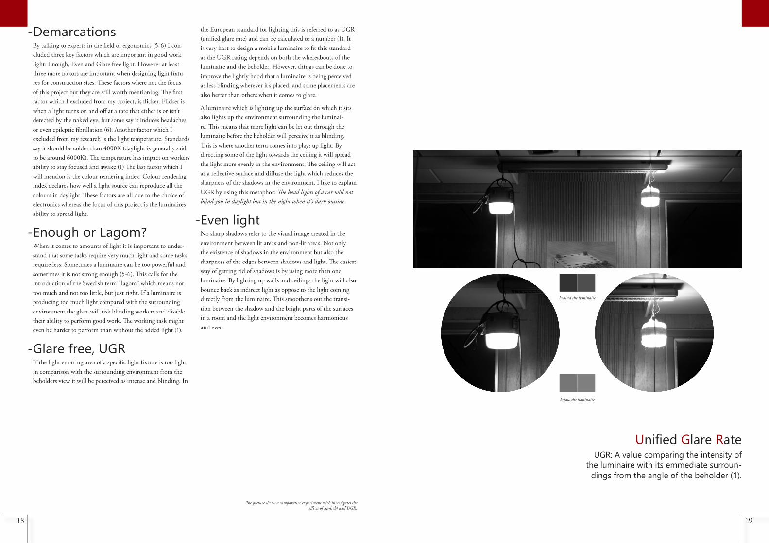
A luminaire which is lighting up the surface on which it sits also lights up the environment surrounding the luminai-re. This means that more light can be let out through the luminaire before the beholder will perceive it as blinding. This is where another term comes into play; up light. By directing some of the light towards the ceiling it will spread the light more evenly in the environment. The ceiling will act as a reflective surface and diffuse the light which reduces the sharpness of the shadows in the environment. I like to explain UGR by using this metaphor: The head lights of a car will not blind you in daylight but in the night when it’s dark outside.
-Even lightNo sharp shadows refer to the visual image created in the environment between lit areas and non-lit areas. Not only the existence of shadows in the environment but also the sharpness of the edges between shadows and light. The easiest way of getting rid of shadows is by using more than one luminaire. By lighting up walls and ceilings the light will also bounce back as indirect light as oppose to the light coming directly from the luminaire. This smoothens out the transi-tion between the shadow and the bright parts of the surfaces in a room and the light environment becomes harmonious and even.
The picture shows a camparative experiment wich investigates the effects of up-light and UGR.
Unified Glare RateUGR: A value comparing the intensity of
the luminaire with its emmediate surroun-dings from the angle of the beholder (1).
behind the luminaire
below the luminaire

20 21
A lit up water container was inspiration to the prduction method for the dome. A methood which later came to my knowledge other luminaires allready used.

22 23
Process-Sketches and models
This semi-scientific process also included a set of different ex-periments with special models made to distribute the light. It involved making lenses, diffusors and reflecting surfaces. The process continued into different body storming models which included varying sizes of both the dome and the object as a whole. in this process I learned how large the object should be, how I could direct the light and how it could be placed at the work site. The entire modelling process resulted in a body storming prototype which came to match the finished result. This model allowed me to test the functionality of the shape but not the light. Another model with a vacuum formed dome was made to be used in user tests. This model was then
tested by a painter at two different times, all together for about three weeks. Finally I got the opportunity to print a model in 3D printer by a Chinese company with visual and functional properties close to a production luminaire. This model was the closest thing to a prototype of this luminaire.In the sketching process the idea of using an additional lamp shade was explored. This was due to my research into ergono-mics which clarified the fact that more light can be produced with less glare if the object has a larger emitting area. Using an additional lamp shade would reduce the glare significantly but how it might look and fully function remain unexplored in this project.
Below: Evolutionary picture of the Luminaire, Some models where destroyed to give way for new versions
Opposite Page: Some of the later sketches leadng to the final shape

24 25
-FunctionsThe stakeholders and their interest as well as the sketch and modelling processes helped me to pinpoint the valid func-tions of a new float luminaire. This gave my product func-tions which some competing luminaries lack. Most important of all functions must remain to be its intended use as a ceiling mounted construction site luminaire for common light, thus, to provide common light. The second most important function according to my research is the function of provi-ding spot lighting when needed. On the larger build sites, the luminaires are being covered in plastic bags to protect them against spray paint. This is in my opinion a result of poor
design. The domes are generally made from polycarbonate. Polycarbonate is also used in motorcycle helmets because it is very durable and because it is possible to paint. By choosing another plastic (with a fatter surface) and by covering it with some kind of wax or other product the plastic bag might be ruled out (7).
-Designing the lightIn the modelling process I researched various shapes of emitting surfaces. I found that most of the light traveling out through an opaque medium, travels perpendicular to the surface. I made a model which was supposed to direct
MAIN FUNCTIONPROVIDE COMMON LIGHT
SECONDARY FUNC-TIONS
PROVIDE EXTRA LIGHTDRIVE EXTRA LIGHT
PROVIDE POWER
DESIRED FUNCTIONSAFFORD GRIP
AFFORD LIFTINGAFFORD CLEANINGAFFORD STORING
WITHSTAND WEATHERWIDTHSTAND HEAT
Illustration: To be able to emmitte more light it is best to either make a larger emmittive surface to correspond with the increased
intensity of the light source or to add another luminaire.
Intense appearance with much light through small surface
Less intense appearance with equal ammounts of light through larger surface
Less intense appearance with equal ammounts of light through two surfaces
Large picture: Picture showing the fenomena of light being mostly emmitted perpendicular to the surface.
the light when placed on the floor. The shape afforded it to be placed on a series of faces which would enable it to spread the light towards the work area. It had a rather sharp bottom edge which created dark spots in the light spread as shown in the picture below. As the main task of the luminaire was to provide a good common light this ruled out sharp edges in the dome. This thesis, that the light travels mostly perpendi-cular from the emiting surface was proved as I received a 3D printed dome from the model maker. One surface which was supposed to be flat had warped into a lofted surface which worked much like a convex lens. It had a focus point of about 50 or so centimetres. If the distance was larger it created a
circular dark spot on the wall.
Another consideration which is important when designing any luminaire is to match the power of the light source with the size of the lumainire and how it’s intended to spread the light. This is illustrated below. My design should ideally carry a light source with 0-2500 lumen depending on the environ-ment and working task.

Model used to understand the possibilities of placements using hooks
Size explorations Model showing possible looks if it were to be injection blow moulded as an entity
Experiment to understand light emission from curved diffusers

28 29
-Closer to a productMy knowledge grew throughout the project and the process came to conclusions. The light should be alloud to travel om-nidirectionally (like most luminaires on the market) in con-trast to the strictly one directional GARO Ball Luminaire. To make a luminaire which spreads the light in an omnidirectio-nal way the luminaire should be made in at least two peace’s which of whom one needs to house the cabling and the power outlets. Because of these components this piece of the lumi-naire should not let through light. This piece which I here on will refer to as the body will need to be smaller than the other part which I will refer to as the diffusor. This Allows light to slip past the body and spread the light in all directions.
I strived to make the body as small as possible. This would maximize the amount of light traveling passt it. There were three main components which constraint and the size and shape of the body. The first one was the light source and its socket which in total measured between 13 and 17 cen-timetres (depending on the light source). The two other components where the two power outlets. It was important that the light source would end up at a suitable height in the diffusor as the light sources in themselves are not capable of spreading the light towards their sockets. One model showed
Left: Models leading to the shape which directs the work light
Below: Proof of concept model, Used in user tests and in comparison, with GARO ball
Above: The cable reel is an important part of the Luminaire. It was considered in most of the models.
Below: Body storming with the foam model
Model for bodystorming, Used to show and evaluate the shape and it’s possibilities
that the light source could be partly situated within the body. Sketches of different placements for the components as well as cardboard models helped me to come up with the solution. The socket was lowered down between the two power outlets which allowed for two 45 degree offcuts from the whole shape enabeling the luminaire to be tilted towards the work area.
To test the functionality, I made a foam model to correspond with the body part and the diffusor. The model was used in bodystorming. It came very close to the final shape. The hook out of steel wire came to have a multiple functionality. It can be used as cable reel, hanger, bottle opener and tripod mount. The hook itself was developed in many steps and the material took its inspiration from the Gnosjö region of Småland where GARO has its production.
-Proof of conceptMy target to design a luminaire which facilitates transport and which spreads light more evenly from a placement which is away from direct sight. The body storming model out of foam let me test the possibility of placing the light away from sight but helped me little to prove the full concept. To prove the concept it would need to spread light and at least be semi-functional. I still couldn’t prove it would better in spreading the light than the GARO Ball or any other on-

30 31
struction sight lighting equipment. Therefore, I proceeded to make a functional model which aimed to proove the concept. It was made of playwood, cardboard and PET plastic.
The new model came very close to fulfilling all the para-meters I set out for it in terms of shape and functionality. Its weakness was the diffusor part which didn’t turn out as opalescent as I had hoped. Together with Torbjörn Laike at LTH I made comparing measurements between the GARO Ball and my model. My model lit up the ceiling when hung in the ceiling twice as much as the GARO Ball. The same or equal amounts of light was cast on the walls in the room from the two luminaires. Less light from my model hit the floor compared to the GARO Ball. This has two important reasons: The first reason was the fact that my model carried a 1500 lumen light source and the GARO produce between 2000 and 2500 lumen. The second reason is the fact that my model threw more of the light else ware. What’s important to consider is the opalescens of the model which limited its capability of spreading light. With a better diffusor more light
would be cast towards the ceiling.
A clear fact arouse when we compared the luminaires light intensity measured at the brightest spot in comparison with the immediate surrounding background of the luminaire. This was measured as if a worker would be standing a few meters away and looking up at an approximate angle of 20 to 35 degrees. This is a measurement in which I claim the power of the light source has no real importance as it has more to do with comparing the luminaires capability of spreading the light.
The goal with designing the dome was to make it spread light omnidirectionally. This creates the best common lighting from this kind of luminaires. I do not claim my luminaire to be better than any other luminaire on the market except the GARO Ball in this aspect. It is however, better in many other aspects such as it’s shape will easier afford many placements other luminaires wouldn’t. It is also slightly better at directing the light when it’s being used as spot lighting. For this purpo-se, an additional lamp shade or larger dome should be fitted. The dome I decided to go with has the advantage of being relatively small. This makes it easier to carry and store. It is also designed to be standing with the dome diected towards the floor. This eases moving the luminaire when it’s lit and operating the power outlets and light switch.
-Chinese model makerAs the last step in my model making process, I got a chance to try and evaluate a Chinese model maker. I chose to do it because it was the only way I could create something simmi-lar to an injection blow moulded dome. It took about two weeks off from my process which had to be shortened leaving me with only eight of weeks work in total. This was due to the long shipping times and the fact that the vital dome broke on the way to Sweden. This was mainly due to poor packa-ging from the model maker. They did a good job making the model, but I will probably never do it again. My main reason being the fact that you leave too much of the responsibility in someone else’s hands. The distance leaves no room to critique the work before paying. This leaves you alone with little or no warranty for the status of your model.
Upper right: Measurements where taken on the model and on the GARO Ball luminaire. There where no pictures taken at the occa-tion. This picture is of a similar situation later in the project.
Lower right: The dome broke on its first voyage fromn China

32 33
Model used to compare reflective and opalescent surfaces

3534
4000k, a luminaire
Opposit Page: Illustration of the functionality of the luminaire
74°
45°
141°
96°
R20
R20
R20
R2553
,51
66
R4
130°
FUNKTIONALITY, HOOK
40
124,
43
150,
72
MEASUREMENTSSPECIFIED TO MM
266,8
2
164,
43
CARBINER 4,5mm
59,2
141
3
354
,76
9
3,07
21,4
827
,94
5,86
15,7
919
,74
94,2
114
,4
66,71 14,15 15,77 5,855519,227,48
2
2
R3
R2
R10
2,1
5
10
R3
5
1,5
647
,47
2,93
12,12
11,17
A
A
A A
ISO 25
R7,59
R3,62
DIMABLE HUE LED1000-2500 LUMEN
E27 SOCKET
LIGHT SWITCH

36 37
38 39
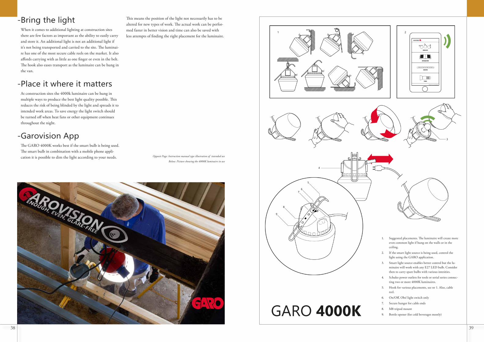
-Bring the lightWhen it comes to additional lighting at construction sites there are few factors as important as the ability to easily carry and store it. An additional light is not an additional light if it’s not being transported and carried to the site. The luminai-re has one of the most secure cable reels on the market. It also affords carrying with as little as one finger or even in the belt. The hook also eases transport as the luminaire can be hung in the van.
-Place it where it mattersAt construction sites the 4000k luminaire can be hung in multiple ways to produce the best light quality possible. This reduces the risk of being blinded by the light and spreads it to intended work areas. To save energy the light switch should be turned off when heat fans or other equipment continues throughout the night.
-Garovision AppThe GARO 4000K works best if the smart bulb is being used. The smart bulb in combination with a mobile phone appli-cation it is possible to dim the light according to your needs. Opposit Page: Instruction manual type illustration of intended use
Below: Picture showing the 4000K luminaire in use
This means the position of the light not necessarily has to be altered for new types of work. The actual work can be perfor-med faster in better vision and time can also be saved with less attempts of finding the right placement for the luminaire.
1. Suggested placements. The luminaire will create more even common light if hung on the walls or in the ceiling.
2. If the smart light source is being used, control the light using the GARO application.
3. Smart light source enables better control but the lu-minaire will work with any E27 LED bulb. Consider then to carry spare bulbs with various intesities.
4. Schuko power outlets for tools or serial series connec-ting two or more 4000K luminaires.
5. Hook for various placements, see nr 1. Also, cable reel.
6. On/Off, Obs! light switch only
7. Secure hanger for cable ends
8. M8 tripod mount
9. Bottle opener (for cold beverages mostly)GARO 4000K

40 41
Opposite Page: Ceiling mounted common light with two additio-nal spot lighting luminaires.
Upper left: Shuko power outlets. The lids flip upwards to ease reach when the luminaire is hung in the ceiling.
Lower left: The light switch is situated under the hook. It is somewhat hard to reach but rarely used.
Upper right: The possibility to unscrew the dome from the body called for product semantics. The pattern across the edge of the body resembles the ones used at many screw lids. This makes it easier to understand the scrw mount.

42 43
Opposite Page: The light source is partly situated between the power outlets.
Upper left: Two hooks ensures a safe and effective catch for the cable ends. It is effective enough for carrying even at the packet holder of bicycles. In the middle of the black bracket there is an M8 threaded tripod mount.
Lower left: The luminaire when the cable is unwound.
Upper right: The body part, simple and useful.

44 45
-Common lightingBy changing to the E-27 socket and using a 2000 lumen LED I significantly improved the common light produced when hung in the ceiling. The GARO luminaire directs most of its 2500 lumen straight towards the floor. Instead the 4000K luminaire spreads light towards the ceiling and the walls. This produces a common lighting which is good and bright enough for work in larger areas of the work site surrounding it. However, as earlier mentioned enough light can in most cases only be achieved using more than one luminaire. The 4000K luminaire has a larger diffusing area which is can create more light without being perceived as equally blinding. Also, the contrast between the diffusor and the wall in the background is lower with the omnidi-rectional lights pread. Most other float luminaires have this kind of lights pread eccept the GARO Ball. They are larger and less handy then the GARO Ball. The 4000K is a good combination between these criterias, size and function.
-Blurred shadowsBy carefully designing the dome and the body parts I mana-ged to create up-light. This drastically blurred out the lines between the shadows and the light comparing the GARO Ball luminaire and my user test model. There is lower contrast in the environment. The result is also due to the better and larger diffusing area of the 4000K luminaire compared with the GARO Ball. This photographic experiment was carried out at similar placement in the ceiling in a darkened-out
brighter environment
room. The result further stresses the importance of omnidi-rectional light spread in these kinds of luminaires.
-Spot lightingWhen meeting up with the CEO and the sales manager of GARO in a post project meeting, I got the chance to get feed-back on my model. This gave me information which helped me understand the project better and to evaluate. The truth being; the most innovative thing according to them was the angles of the body. This was something they had never seen before. These angles force the builder to adapt the light by directing it towards the working area wich reduces glare for other workers in the room and disables the worst-case place-ment on the floor. As the workers need a lot of light for some tasks, glare might never disappear but we can always do our best as designers to improve the situation. To make the vision better at worksites the future calls for a compleetly new type of luminaire or system but I believe the float luminaires will remain as the only luminaire suitable for some kinds of work. The 4000K luminaire shows in this picture that workers in other areas of the room are less lightly to be blinded by the work light when its main direction is away from the beholder.
GARO BALL GARO 4000K
reduced contrast
reduced glare

46

48 49
-Future improvementsI would have liked the opportunity ty try my concept using Phillips Hue. This would enable me to understand the power of smart lighting at build sites.
Due to the fact that lagom light only can be achieved if the work light can be tuned to suit the work and work site. The ability to dim the light is a crucial necessity. To make a func-tional system is a project in its own, another function analysis should be made etc. So, Garovision is the concept in which you use your phone to set up the light to match your work. Maybe the App will tell you where you should place the light and then automatically tune in to the environment.
As explained earlier there are smart light sources from a whole range of companies hence also the chance to try smart lighting in my light fixture at build sites. This will remain the topic of another project.
The body part of the luminaire is what I regard as the most
successful result of the project. The components placement within it and the way a dome is screwed on to it affords a great number of possibilities. The dome part as it stands at the end of the project is also a great product. It is the best as it is small and easy to carry. But to be used as effective extra light at the build site there should be made a larger lens shaped diffusor which would further decrease the contrasts in the en-vironment and the lightly hood of being blinded by its light. Alternatively, there should be made a lamp shade which easily should be clamped in between the body and the dome parts as shown in a sketch made early in the project.

50 51
-The resultSome Swedes might misinterpret the word industrial design, associate it with mere aesthetic qualities or as in the case of Swedish language, prefer to understand the word as design of industries rather than for industrial application. The latter is due to an ill functioning translation from the English word industrial to the Swedish word industri which simply means industry. Because of this translation in Sweden we more often come to hear the commonly used and very misleading word design. The Swedish word design doesn’t mean design in the wider scope but instead the activity of giving form. Design in the English world is a very wide concept covering everything which has to do with solving problems. It is more widely used in the field of engineering in a form at least similar to; of an actor thought out solution for a specified problem. This is what I regard as the main idea of industrial design. Without a problem it simply is not a design. Problems do seldom come alone, and it is the task of an industrial designer or an engineer to find the main problem and to attempt to solve it together with perhaps a series of other smaller ones (without creating too many new).
This is something which is very hard to do if you as a designer have little experience in the activities of your target group. It is also virtually impossible to design a good solution for a problem in the package of a product without making a series of models which in each step refines the exact dimensions and functions. The feedback from the target group is a vital step in the process as without it neither the dimensions or the functions can be proven to work, and no truthful conclusion
can be made.
To relate to my own project and to critically value it I have to say that my product could have been realized into production. But not as it stands at the end of the project. I couldn t́ say with confidence that it would be the best solution to my main problem in the project which remains to be glare in the buil-ding environment. I think the result could have been further enhanced.
I had a desire to make a functioning product which I hoped to be understood as useful and thus, well-conceived by all the stakeholders in the project. This is a problem which all de-signers will encounter. It’s the problem of having to convince stakeholders and to make them understand the importance of the pinpointed problems and that the designed solution is in fact the best one. All the stakeholders can not be equally respected for their opinions. If they are the project will not end up a good solution for the user. Often the design is being tweaked beyond recognition by the deciding organs of the companies or aborted as something which is not profitable or doomed to fail. I did try to stay out of this pit hole but still I’m filled with doubt regarding many aspects of the result. To give examples I could have chosen the body of the luminaire to be made of sheet metal, which would have given it a longer expected life circle and probably constraint the aesthetics to something perhaps even more suitable for build sites. I could have gone for a completely other solution than a float luminaire which would greatly reduce the glare in the environment. Both ideas where considered but not realized simply because I didn’t think the producer of the previous model would invest in it. This also showed to be true as
Evaluation GARO made it clear to me that they already had an expen-sive injection moulding machine and hoped to produce the next generation in a similar way. They also seemed to think that other concepts where to vague and that they already had a working concept.
Would I have gone for the best solution already in the start GARO wouldn’t have appreciated it as much, but the solution would have been better and possibly worth investing in from elsewhere. Due to my desire to constrain myself to meet the stakeholders I learned a lot about the industry which was also my intention. In this aspect, the project was a great success even though the result in the end didn’t serve the best solu-tion to the problem.
Now I would like to take the opportunity to give more weight to the importance of modelmaking. The making of models and mock-ups should continue for the entire length of the project. To sit down and to think that it is time to make the final prototype is something which in most cases is an illusion. The final prototype is simply the last model there is time to make before the actual production of the product initializes. Models which are purely made for exhibitions will take unnecessary time from the development stages of a product, especially in the school environment. Don’t get me wrong, models for exhibitions or for selling a concept have importance too for the process as they demand the designer to choose wisely the right edge treatments, surfaces, materials and dimensions. This is a process which like all modelling processes should be performed hands on in control of the designer, either by or close by.
The final prototype is rarely the same as the model made for selling the idea of the product. In fact, I claim that they should never be. I learned this through trying to sell the lu-minaire to GARO. They came with a ton of feedback on my model which I understood from their perspective was valid.
This feedback needs to be asserted and considered before the next model is made and then the next until there is an agreement and production is possible. This really clarifies the importance of continuing the modelling process and not to waste time trying to produce a result too early in the project. Had I not made my exhibition prototype in China I would have had time and money to make four or five more models which together with an earlier meeting with GARO would dramatically change the outcome of the project. This also stresses the importance of understanding and having frequ-ent meetings with the stakeholders. You might now say that this leads me to a contradiction with my earlier statements regarding stakeholders (that they in some ways may limit the best result to be achieved). However, this second conclusion has more to do with whether you want your design to be app-roved and finalized. If you do you shall have to have a living dialogue with the stakeholders.
What is most important remains to be the main problem and to solve it. I merely want to highlight by this reasoning that the stakeholders and the process itself should somehow be in-clined to help solving the main problem and not to come into conflict with the realization of the final and hopefully best solution. This can only be achieved if you know what your customer really wants (which in all cases isn’t wat they think they want). This can only be known through communication.
I managed to create the best solution in the given circum-stances marked by the industry, the time constraints and the poor decision to not continuing the modelling process. The result however has many faces and as the main goal with all educational activities is to learn. I learned a great deal due to acting with many stakeholders whom gave me the real-world input which I during most of the education lacked. This is the main reason I can say that the project is for me a personal and educational success.

52 53
-Project managementMost things have constraints, endpoints or borders. Projects have both borders which limit the extent and two points, one for start and one for stop. The project owner decides if the project should be launched or not, how much money it should cost and when the result should be delivered. Who then is the project owner in a university degree project?
This question doesn’t appear to have a clear answer. One could argue that it is the student. The student however doesn’t have the power to fully decide the extents or time frame. Yet the student is the main stakeholder in the project. The exami-ner of the work has the power to launch the project and grant the result with a degree. The examiner does not have any di-rect interest in the project and should therefore in my opinion not held with the title project owner. This is relevant when it comes to understanding the differences between the students work and that performed by a professional in the field.
The owner of a student project is most often the student, or a fictive figure or company given by the student. This means that there are no real relationships between the project owner and its executor as they are the same person. This means the student has all the power to decide what to do as long as the examiner and the supervisor approve, and it fits within the timeframe. It is up to the student to draw the line between different parts of the project. This means that there is no real need for scheduling or to make calculations regarding costs etc. Examiners and supervisors do not exist in the industry. In the student project they function as some sort of guidance or even controlling organ which take care of some tasks normal-ly cared for by the project owner.
What is the problem with this?
In my opinion this sometimes leads to quite unprofessional work as the students only must live up to their own expecta-tions as project owners. Often students guess what the indu-stry might be looking for or use themselves as target group. The examiner and the supervisor also have a difficult task to try and keep projects within the boundaries. In doing so they
risk taking control of the project from the student.
As the curriculum already specifies several presentations and deadlines. Simply keeping up with this structure is enough to succeed in finishing the project. The student doesn’t need to make the schedule and survives using simpler Gantt or Burn Down charts to fit the courses timeframe.
So, the project plan which I made initially in the project had no real importance to the project. At least not when it came to the specified dates. It was useful as a guiding structure and the project was finished in time without any stress or agony. The project seemed to be a 15 weeks project but was deduced to 10 weeks due to presentation dates and master application deadlines. Further two weeks disappeared when I chose the Chinese model maker.
One of the main problems with my project was that I had to use GARO as a fictive project owner of my project. I had to guess what they would think rather than know. This took time and sometimes left me a bit alone in my process. There to guide me was instead the CEO of Jelmtech Carl-Fredrik Emilsson who helped me at least with understanding if I was on something like the right track (something GARO would like). When I met up with GARO after the project, I had ma-naged to make something which they thought was interesting but not close enough to fully accept.
Opposite page: Project plan and Gantt chart


5 Laike, Torbjörn; Professor, Department of Architecture and Build Environment, Lunds Universitet. [email protected]
6 Hemphälä, Hillevi; Biträdande Universitetslektor, Ergonomi och Aerosolteknologi, Lunds Universitet. [email protected]
7 CarlFredrik Emilsson; CEO, Jelmtech. carl-fredrik.emilsson@ jelmtech.se
http://www.garo.se/tillfallig-el/byggbelysning/byggarbetslam-por/bygglampa-ball-230v-2-0
https://www.kjell.com/se/produkter/el-verktyg/belysning/ljus-kallor/smart-belysning/philips-hue/philips-hue-e27/philips-hue-startpaket-smarta-led-lampor-3-pack-p50816
https://kaffebrus.com/produkt/lagenergilampa-spiral-dagsljus
https://www.lampornu.se/philips-corepro-ledbulb-e27
https://www.pricerunner.se/pl/1-3968527/Mobiltelefoner/App-le-iPhone-6-32GB-priser
REFERENCES
PICTURES
LITTERATURE
PERSONAL COMMUNICATION
1 Belysningsstandarden för inomhusbelysning SS-EN 12464-1:2011
2 Bygghälsans Forskningsstiftelse. (1992). Praktisk synergonomi i byggbranschen, Arbetsmiljöinstitutet: Stockholm
3 Bygghälsans Forskningsstiftelse. (1988). En synergonomisk under sökning av 41-55-åriga byggarbetare, Arbetsmiljöinstitutet: Stockholm
4 Byggindustrins Centrala Arbetsmiljöråd. (2017). Arbetsskador i byggverk samhet 2017, Luleå tekniska universitet
74°
45°
141°
96°
R20
R20
R20
R2553
,51
66
R4
130°
FUNKTIONALITY, HOOK
40
124,
43
150,
72
MEASUREMENTSSPECIFIED TO MM
266,8
2
164,
43
CARBINER 4,5mm
59,2
141
3
354
,76
9
3,07
21,4
827
,94
5,86
15,7
919
,74
94,2
114
,4
66,71 14,15 15,77 5,855519,227,48
2
2
R3
R2
R10
2,1
5
10
R3
5
1,5
647
,47
2,93
12,12
11,17
A
A
A A
ISO 25
R7,59
R3,62
DIMABLE HUE LED1000-2500 LUMEN
E27 SOCKET
LIGHT SWITCH

ABSTRACT There are great risks of a multi-tude of injuries due to poor
light at construction sites. This leads ultimately to costly counteractions from society. The goal of this project was to put construction workers’ situation in the spotlight by giving construction sites better vision ergo-nomics through providing enough, even and glare-free light. With the GARO Ball luminaire as benchmark I designed a luminaire with hooks and loops out of steel wire and a shape which asks the builder to model
the light according to needs. To dim the light there is new technology in other fields which enables an easy way to smart construction
sight lighting. Better placements of the luminaire and the possibility to dim the light created better vision conditions
at indoor construction sites. The project involved exter-nal expertise and guidance as well as interviews and
user tests. The result was measured in an ex-periment which proved it to reduce
contrasts in the environment up to three times compa-
red with the GARO Ball.