Embed Size (px)
Citation preview
产品手册 ASF01
- 0 -
广州奥松电子有限公司 电话:400-630-5378 www.aosong.com v1.0-20180316
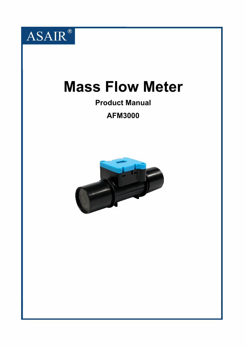
Mass Flow Meter Product Manual
AFM3000
产品手册 ASF01
- 1 -
广州奥松电子有限公司 电话:400-630-5378 www.aosong.com v1.0-20180316
Features
� Low pressure drop
� Flow range: +/- 200 slm (bidirectional)
� Accuracy 1.5% m.v. (typical)
� Very fast update time
� Fully calibrated & temperature compe-
nsated
� Low zero drift
Product Summary
The AFM3000 sensor is Aosong’s
digital flow meter designed specifically for
ventilator applications. It measures the
flow rate of air, oxygen andother
non-aggressive gases with superb
accuracy. A special design of the flow
channel results in the very low pressure
drop through the flow body of the sensor
making it extremely suitable for very
demanding applications, such as medical
ventilation and respiratory applications.
The AFM3000 operates from a 5
Voltsupply voltage and features a digital
I2C interface. The measurement results
are internally linearized and temperature
compensated.
The outstanding performance of this
sensor is based on Aosong’s sensor
technology,which combines a thermal
sensor chip and a high-performance
integrated 24-bit AD acquisition CMOS
microprocessor. The flow rate of the gas
is measured by a thermal sensor element
which assures very fast signal processing
time and bidirectional measurement with
best-in-class accuracy.
Applications
Medical、Process automation、Burner
control、Fuel cell control、Spectroscopy、
Environment monitoring、Laboratory
OEM industry customization
and solutions
Our company is committed to research
and development of various sensors, with
professional R&D laboratories and equipment,
supporting a variety of simulation
environment experimental conditions, to
create high-quality product production and
inspection process.The AFM3000 is one of
the chips independently developed and
manufactured by our company. The flow
range and independent flow channel
structure can be customized according to the
application site and customer needs. Aosong
professionally provide customers with
complete application solutions
产品手册 ASF01
- 2 -
广州奥松电子有限公司 电话:400-630-5378 www.aosong.com v1.0-20180316
Content
1. Sensor performance ................................................................................................................................... - 3 -
2. Sensor electrical characteristics ............................................................................................................... - 4 -
3. Sensor communication .............................................................................................................................. - 4 -
3.1 I2C communication interface characteristics and timing ............................................................. - 5 -
3.2 Sensor data collection ..................................................................................................................... - 5 -
3.3 Read device ID ................................................................................................................................. - 6 -
3.4 Reset command................................................................................................................................ - 6 -
3.5 AFM3000 I2C command definition ................................................................................................. - 6 -
3.6 AFM3000 CRC calculation routine ................................................................................................. - 7 -
3.7 Flow conversion formula ................................................................................................................. - 7 -
4. Pin definition ................................................................................................................................................ - 8 -
5. Typical circuit ............................................................................................................................................... - 8 -
5.1 Typical circuit connection ................................................................................................................ - 8 -
6. Dimension(unit:mm) .............................................................................................................................. - 9 -
6.1 AFM3000 dimension ........................................................................................................................ - 9 -
6.2 Machinery parts ................................................................................................................................ - 9 -
7. Model list .................................................................................................................................................... - 10 -
8. Precautions ................................................................................................................................................ - 10 -
8.1 Calibration direction ....................................................................................................................... - 10 -
8.2 Inlet flow conditions ........................................................................................................................ - 10 -
8.3 Temperature compensation .......................................................................................................... - 10 -
8.4 Processing .................................................................................................................................... - 11 -
8.5 ESD ............................................................................................................................................... - 11 -
9. Accuracy statement .................................................................................................................................. - 11 -
10. Important notices .................................................................................................................................... - 11 -
Product Manual AFM3000
- 3 -
Guangzhou Aosong Electronics Co., Ltd. Phone:400-630-5378 www.aosong.com V2.1
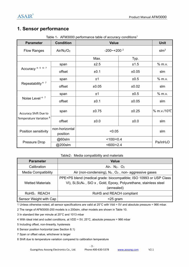
1. Sensor performance
Table 1:AFM3000 performance table of accuracy conditions1
Parameter Condition Value Unit
Flow Ranges Air/N2/O2 -200~+200 2 slm3
Max. Typ.
Accuracy 4,5,6,7
span ±2.5 ±1.5 % m.v.
offset ±0.1 ±0.05 slm
Repeatability 4,7
span ±1 ±0.5 % m.v.
offset ±0.05 ±0.02 slm
Noise Level 4,7
span ±1 ±0.5 % m.v.
offset ±0.1 ±0.05 slm
Accuracy Shift Due to
Temperature Variation 8
span ±0.75 ±0.25 % m.v./10℃
offset ±0.0 ±0.0 slm
Position sensitivity non-horizontal
position <0.05 slm
Pressure Drop @60slm <100/<0.4
Pa/inH2O @200slm <600/<2.4
Table2:Media compatibility and materials
Parameter Value
Calibration Air,N2,O2
Media Compatibility Air (non-condensing), N2 , O2 , non- aggressive gases
Wetted Materials
PPE+PS blend (medical grade: biocompatible; ISO 10993 or USP Class
VI), Si,Si3N4 , SiO x , Gold, Epoxy, Polyurethane, stainless steel
(annealed)
RoHS,REACH RoHS and REACH compliant
Sensor Weight with Cap <25 gram
1 Unless otherwise noted, all sensor specifications are valid at 25°C with Vdd = 5V and absolute pressure = 966 mbar.
2 The range of AFM3000-200 models is ± 200slm, other models are shown in Table 10.
3 In standard liter per minute at 20°C and 1013 mbar
4 With ideal inlet and outlet conditions, at VDD = 5V, 25°C, absolute pressure = 966 mbar
5 Including offset, non-linearity, hysteresis
6 Sensor position horizontal (see Section 8.1)
7 Span or offset value, whichever is larger
8 Shift due to temperature variation compared to calibration temperature
Product Manual AFM3000
- 4 -
Guangzhou Aosong Electronics Co., Ltd. Phone:400-630-5378 www.aosong.com V2.1
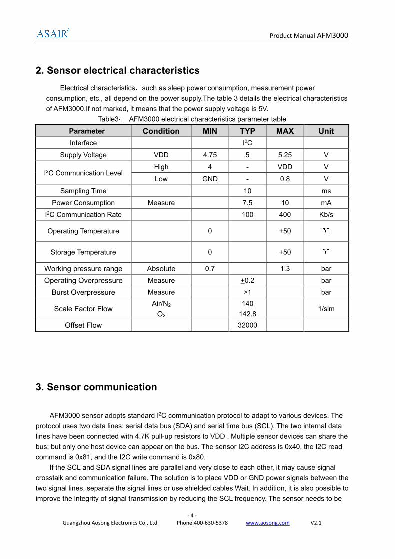
2. Sensor electrical characteristics
Electrical characteristics,such as sleep power consumption, measurement power
consumption, etc., all depend on the power supply.The table 3 details the electrical characteristics
of AFM3000.If not marked, it means that the power supply voltage is 5V.
Table3: AFM3000 electrical characteristics parameter table
Parameter Condition MIN TYP MAX Unit
Interface I2C
Supply Voltage VDD 4.75 5 5.25 V
I2C Communication Level High 4 - VDD V
Low GND - 0.8 V
Sampling Time 10 ms
Power Consumption Measure 7.5 10 mA
I2C Communication Rate 100 400 Kb/s
Operating Temperature 0 +50 ℃
Storage Temperature 0 +50 ℃
Working pressure range Absolute 0.7 1.3 bar
Operating Overpressure Measure +0.2 bar
Burst Overpressure Measure >1 bar
Scale Factor Flow Air/N2
O2
140
142.8 1/slm
Offset Flow 32000
3. Sensor communication
AFM3000 sensor adopts standard I2C communication protocol to adapt to various devices. The
protocol uses two data lines: serial data bus (SDA) and serial time bus (SCL). The two internal data
lines have been connected with 4.7K pull-up resistors to VDD . Multiple sensor devices can share the
bus; but only one host device can appear on the bus. The sensor I2C address is 0x40, the I2C read
command is 0x81, and the I2C write command is 0x80.
If the SCL and SDA signal lines are parallel and very close to each other, it may cause signal
crosstalk and communication failure. The solution is to place VDD or GND power signals between the
two signal lines, separate the signal lines or use shielded cables Wait. In addition, it is also possible to
improve the integrity of signal transmission by reducing the SCL frequency. The sensor needs to be
Product Manual AFM3000
- 5 -
Guangzhou Aosong Electronics Co., Ltd. Phone:400-630-5378 www.aosong.com V2.1
led out, then a 100nF decoupling capacitor should be added between the positive and negative power
supply pins for filtering. This capacitor should be as close as possible to the sensor.
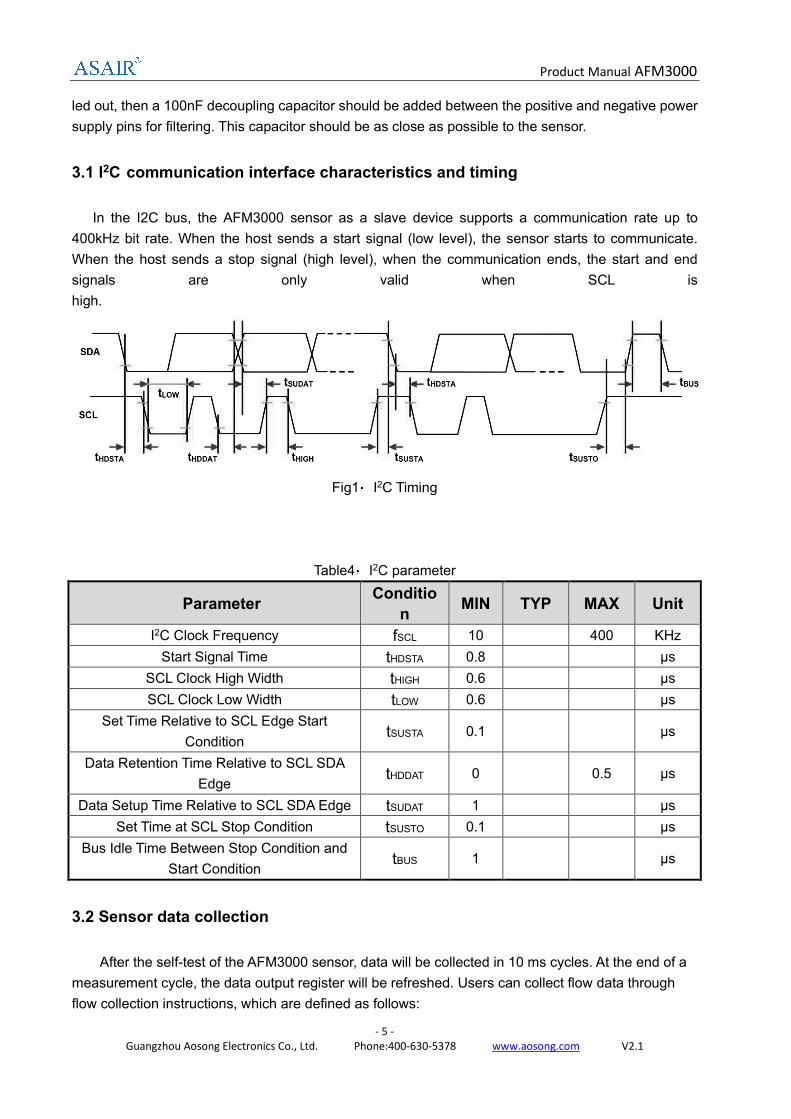
3.1 I2C communication interface characteristics and timing
In the I2C bus, the AFM3000 sensor as a slave device supports a communication rate up to
400kHz bit rate. When the host sends a start signal (low level), the sensor starts to communicate.
When the host sends a stop signal (high level), when the communication ends, the start and end
signals are only valid when SCL is
high.
Fig1:I2C Timing
Table4:I2C parameter
Parameter Conditio
n MIN TYP MAX Unit
I2C Clock Frequency fSCL 10 400 KHz
Start Signal Time tHDSTA 0.8 μs
SCL Clock High Width tHIGH 0.6 μs
SCL Clock Low Width tLOW 0.6 μs
Set Time Relative to SCL Edge Start
Condition tSUSTA 0.1 μs
Data Retention Time Relative to SCL SDA
Edge tHDDAT 0 0.5 μs
Data Setup Time Relative to SCL SDA Edge tSUDAT 1 μs
Set Time at SCL Stop Condition tSUSTO 0.1 μs
Bus Idle Time Between Stop Condition and
Start Condition tBUS 1 μs
3.2 Sensor data collection
After the self-test of the AFM3000 sensor, data will be collected in 10 ms cycles. At the end of a
measurement cycle, the data output register will be refreshed. Users can collect flow data through
flow collection instructions, which are defined as follows:
Product Manual AFM3000
- 6 -
Guangzhou Aosong Electronics Co., Ltd. Phone:400-630-5378 www.aosong.com V2.1
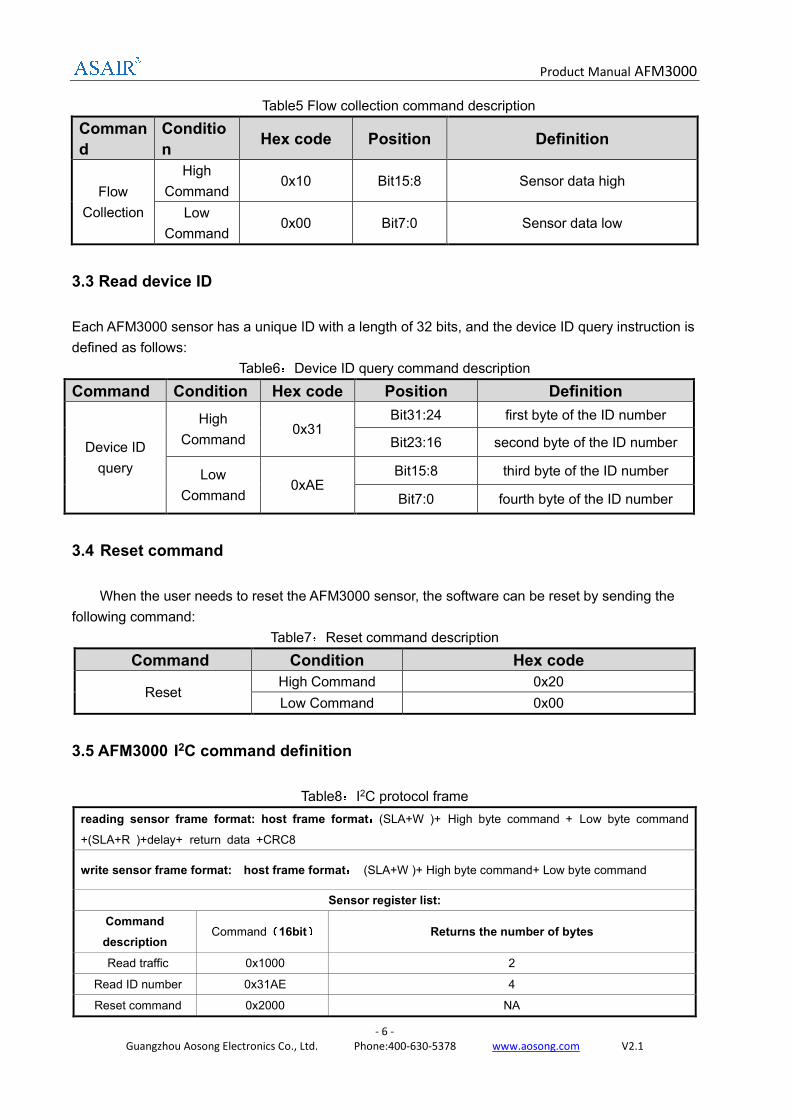
Table5 Flow collection command description
Comman
d
Conditio
n Hex code Position Definition
Flow
Collection
High
Command 0x10 Bit15:8 Sensor data high
Low
Command 0x00 Bit7:0 Sensor data low
3.3 Read device ID
Each AFM3000 sensor has a unique ID with a length of 32 bits, and the device ID query instruction is
defined as follows:
Table6:Device ID query command description
Command Condition Hex code Position Definition
Device ID
query
High
Command 0x31
Bit31:24 first byte of the ID number
Bit23:16 second byte of the ID number
Low
Command 0xAE
Bit15:8 third byte of the ID number
Bit7:0 fourth byte of the ID number
3.4 Reset command
When the user needs to reset the AFM3000 sensor, the software can be reset by sending the
following command:
Table7:Reset command description
Command Condition Hex code
Reset High Command 0x20
Low Command 0x00
3.5 AFM3000 I2C command definition
Table8:I2C protocol frame
reading sensor frame format: host frame format:::
:(SLA+W )+ High byte command + Low byte command
+(SLA+R )+delay+ return data +CRC8
write sensor frame format: host frame format:::
: (SLA+W )+ High byte command+ Low byte command
Sensor register list:
Command
description Command(
((
(16bit)))
) Returns the number of bytes
Read traffic 0x1000 2
Read ID number 0x31AE 4
Reset command 0x2000 NA
Product Manual AFM3000
- 7 -
Guangzhou Aosong Electronics Co., Ltd. Phone:400-630-5378 www.aosong.com V2.1
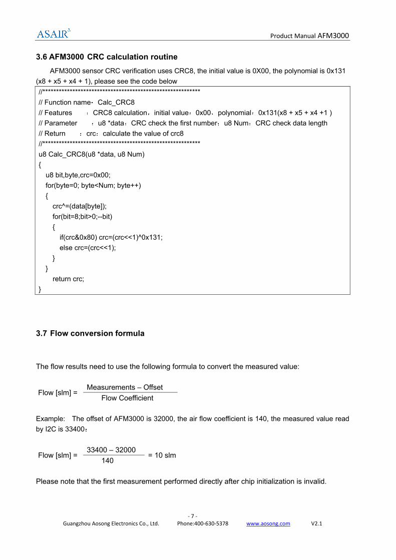
3.6 AFM3000 CRC calculation routine
AFM3000 sensor CRC verification uses CRC8, the initial value is 0X00, the polynomial is 0x131
(x8 + x5 + x4 + 1), please see the code below
//**********************************************************
// Function name:Calc_CRC8
// Features :CRC8 calculation,initial value:0x00,polynomial:0x131(x8 + x5 + x4 +1 )
// Parameter :u8 *data:CRC check the first number;u8 Num:CRC check data length
// Return :crc:calculate the value of crc8
//**********************************************************
u8 Calc_CRC8(u8 *data, u8 Num)
{
u8 bit,byte,crc=0x00;
for(byte=0; byte<Num; byte++)
{
crc^=(data[byte]);
for(bit=8;bit>0;--bit)
{
if(crc&0x80) crc=(crc<<1)^0x131;
else crc=(crc<<1);
}
}
return crc;
}
3.7 Flow conversion formula
The flow results need to use the following formula to convert the measured value:
Flow [slm] = Measurements – Offset
Flow Coefficient
Example: The offset of AFM3000 is 32000, the air flow coefficient is 140, the measured value read
by I2C is 33400;
Flow [slm] = 33400 – 32000
= 10 slm 140
Please note that the first measurement performed directly after chip initialization is invalid.
Product Manual AFM3000
- 8 -
Guangzhou Aosong Electronics Co., Ltd. Phone:400-630-5378 www.aosong.com V2.1
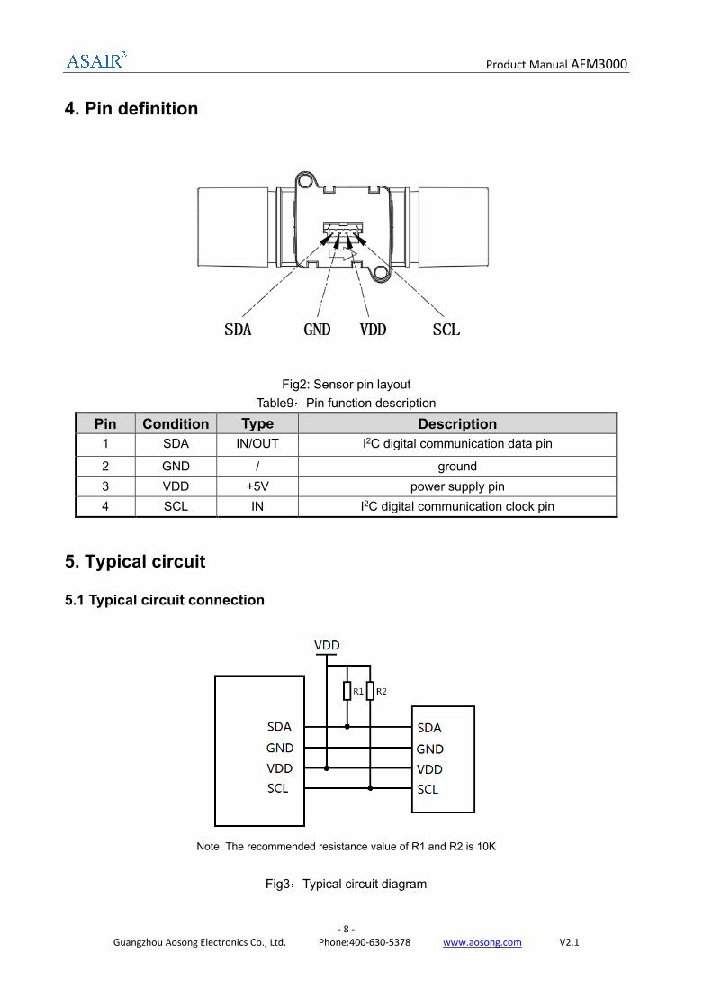
4. Pin definition
Fig2: Sensor pin layout
Table9:Pin function description
Pin Condition Type Description
1 SDA IN/OUT I2C digital communication data pin
2 GND / ground
3 VDD +5V power supply pin
4 SCL IN I2C digital communication clock pin
5. Typical circuit
5.1 Typical circuit connection
Note: The recommended resistance value of R1 and R2 is 10K
Fig3:Typical circuit diagram
Product Manual AFM3000
- 9 -
Guangzhou Aosong Electronics Co., Ltd. Phone:400-630-5378 www.aosong.com V2.1
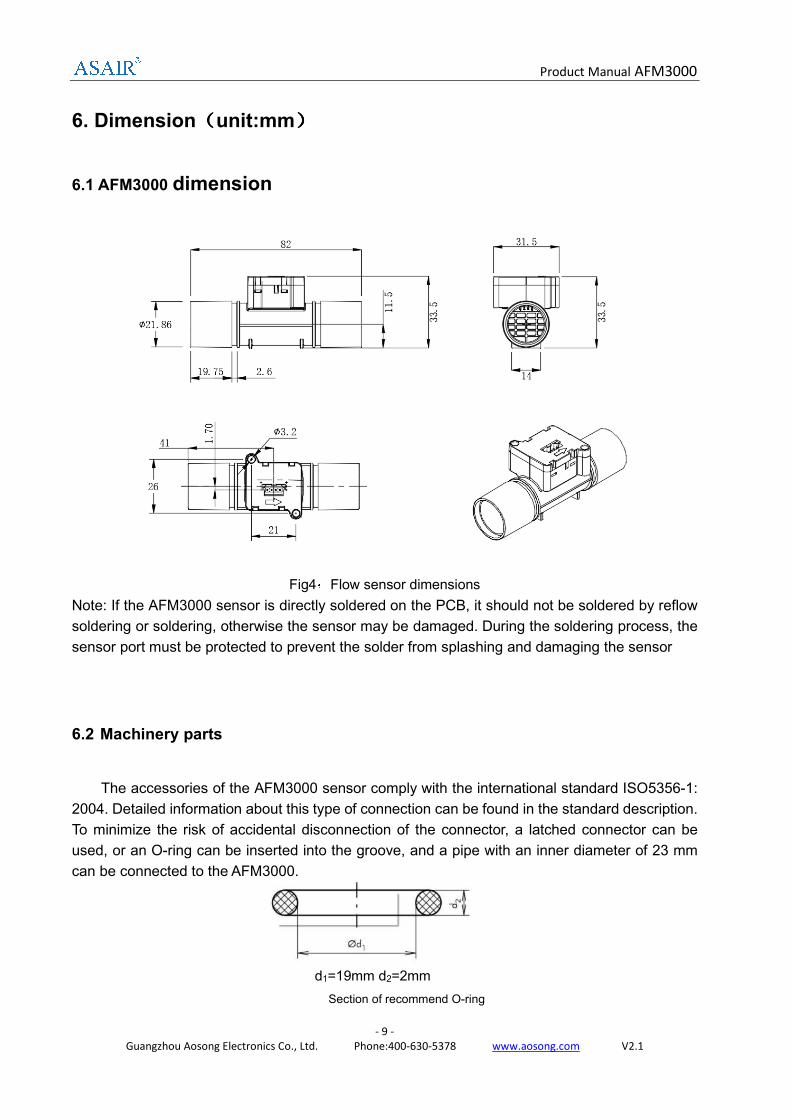
6. Dimension((((unit:mm))))
6.1 AFM3000 dimension
Fig4:Flow sensor dimensions
Note: If the AFM3000 sensor is directly soldered on the PCB, it should not be soldered by reflow
soldering or soldering, otherwise the sensor may be damaged. During the soldering process, the
sensor port must be protected to prevent the solder from splashing and damaging the sensor
6.2 Machinery parts
The accessories of the AFM3000 sensor comply with the international standard ISO5356-1:
2004. Detailed information about this type of connection can be found in the standard description.
To minimize the risk of accidental disconnection of the connector, a latched connector can be
used, or an O-ring can be inserted into the groove, and a pipe with an inner diameter of 23 mm
can be connected to the AFM3000.
d1=19mm d2=2mm
Section of recommend O-ring
Product Manual AFM3000
- 10 -
Guangzhou Aosong Electronics Co., Ltd. Phone:400-630-5378 www.aosong.com V2.1
7. Model list
Table10:model list
Model Range Unit
AFM3000-20 0-20 slm
AFM3000-50 0-50 slm
AFM3000-100 0-100 slm
AFM3000-150 0-150 slm
AFM3000-200 0-200 slm
8. Precautions
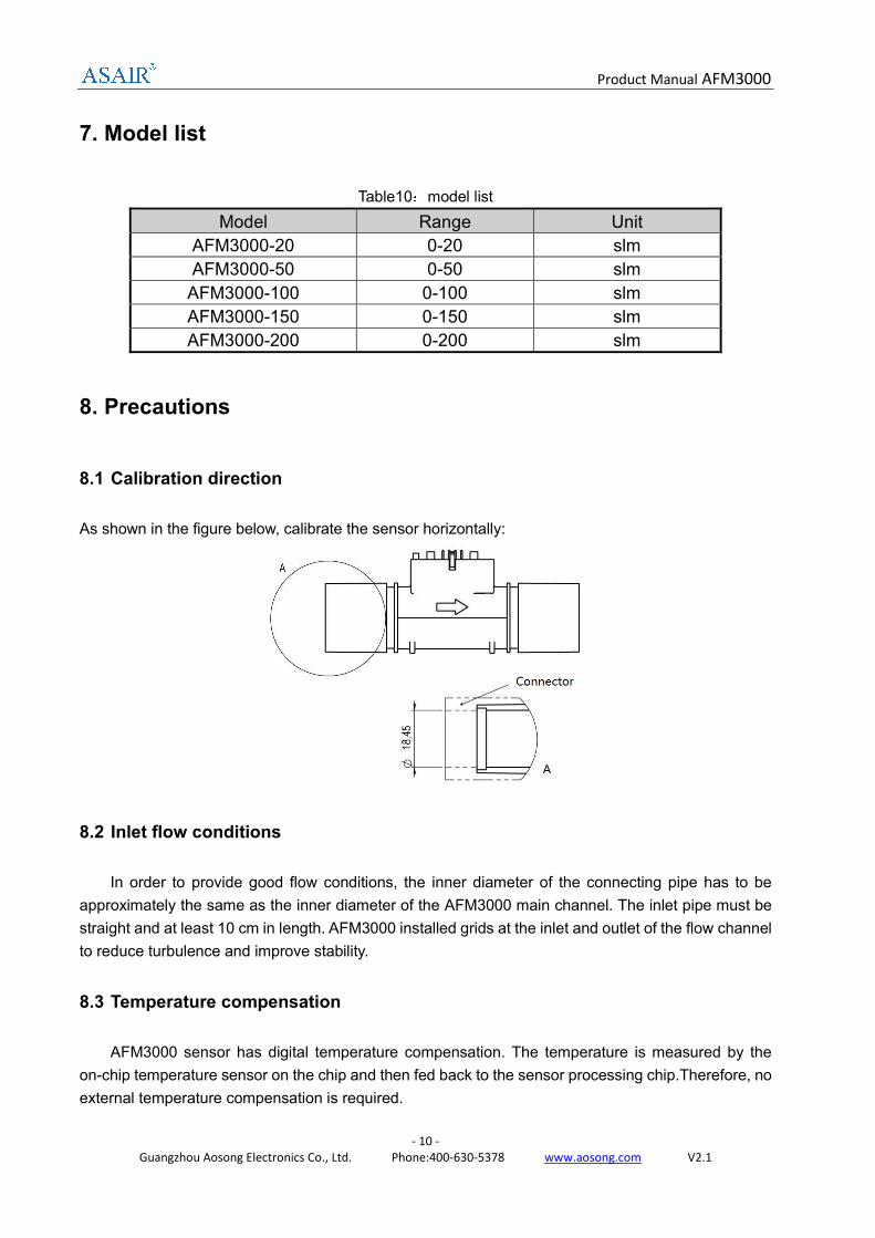
8.1 Calibration direction
As shown in the figure below, calibrate the sensor horizontally:
8.2 Inlet flow conditions
In order to provide good flow conditions, the inner diameter of the connecting pipe has to be
approximately the same as the inner diameter of the AFM3000 main channel. The inlet pipe must be
straight and at least 10 cm in length. AFM3000 installed grids at the inlet and outlet of the flow channel
to reduce turbulence and improve stability.
8.3 Temperature compensation
AFM3000 sensor has digital temperature compensation. The temperature is measured by the
on-chip temperature sensor on the chip and then fed back to the sensor processing chip.Therefore, no
external temperature compensation is required.
Product Manual AFM3000
- 11 -
Guangzhou Aosong Electronics Co., Ltd. Phone:400-630-5378 www.aosong.com V2.1
8.4 Processing
The AFM3000 sensor is sturdy and shock resistant. However, the accuracy of the high-pre
cision AFM3000 may be reduced due to improper operation. Aosong do not guarantee normal
operation in case of improper handling. Note: Avoid any mechanical stress on the solder joint
s of the sensor during PCB assembly or due to PCB assembly.
8.5 ESD
AFM3000 will be exposed to sunlight or strong ultraviolet radiation for a long time, the performance
will be reduced, and the casing will be aging.
AFM3000 meet the following anti-static standards:
- AEC-Q-100-002 (4kV HBM)
- AEC-Q-100-003 (200V MM)
Although the sensor meets these specifications, it does not mean that the sensor itself is
compatible with ESD. When installing the sensor, please place it in an anti-static tray to prevent
electrostatic discharge. In order to avoid damage to the sensor, personnel need to wear an
electrostatic bracelet or wear insulated gloves before touching the sensor.
9. Accuracy statement
The AFM3000 sensor is strictly calibrated in accordance with the AS-WI-RD3370 precision
measurement guidance document. The performance of the sensor under other test conditions is not
guaranteed and cannot be used as part of the sensor performance. Especially for the specific
occasions requested by users, no commitment is made.
10. Important notices
1. Do not use this product as safety or emergency stop devices or in any other application where
failure of the product could result in personal injury (including death). Do not use this product for
applications other than its intended and authorized use. Before installing, handling, using or servicing
this product
2. Please consult the datasheet and application notes. Failure to comply with these instructions
could result in death or serious injury.
3. Based on the information provided by our suppliers, the materials used in this product and raw
materials are harmless to the human body. Aosong has not verified this information through third-party
analysis.
4. For any application using this product, expressly reject any and all responsibilities, including
but not limited to consequential or incidental compensation.