Embed Size (px)
Citation preview

Consolidated Automated Support SystemCASS
Mass InterConnect Solutions...creating order out of wiring chaos
CASS Interface System
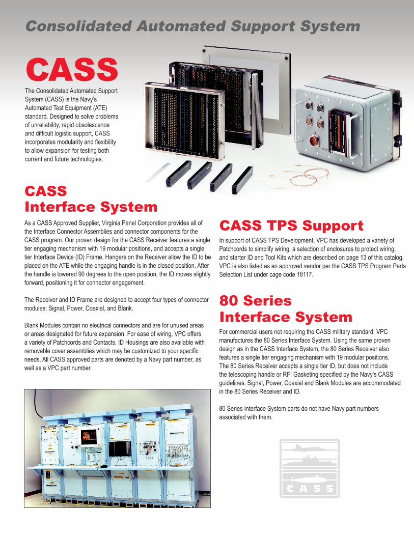
CASS The Consolidated Automated Support System (CASS) is the Navy’s Automated Test Equipment (ATE) standard. Designed to solve problems of unreliability, rapid obsolescence and difficult logistic support, CASS incorporates modularity and flexibility to allow expansion for testing both current and future technologies.
Consolidated Automated Support System
As a CASS Approved Supplier, Virginia Panel Corporation provides all of the Interface Connector Assemblies and connector components for the CASS program. Our proven design for the CASS Receiver features a single tier engaging mechanism with 19 modular positions, and accepts a single tier Interface Device (ID) Frame. Hangers on the Receiver allow the ID to be placed on the ATE while the engaging handle is in the closed position. After the handle is lowered 90 degrees to the open position, the ID moves slightly forward, positioning it for connector engagement.
The Receiver and ID Frame are designed to accept four types of connector modules: Signal, Power, Coaxial, and Blank.
Blank Modules contain no electrical connectors and are for unused areas or areas designated for future expansion. For ease of wiring, VPC offers a variety of Patchcords and Contacts. ID Housings are also available with removable cover assemblies which may be customized to your specific needs. All CASS approved parts are denoted by a Navy part number, as well as a VPC part number.
CASS TPS Support In support of CASS TPS Development, VPC has developed a variety of Patchcords to simplify wiring, a selection of enclosures to protect wiring, and starter ID and Tool Kits which are described on page 13 of this catalog. VPC is also listed as an approved vendor per the CASS TPS Program Parts Selection List under cage code 18117.
80 Series Interface SystemFor commercial users not requiring the CASS military standard, VPCmanufactures the 80 Series Interface System. Using the same proven design as in the CASS Interface System, the 80 Series Receiver also features a single tier engaging mechanism with 19 modular positions. The 80 Series Receiver accepts a single tier ID, but does not include the telescoping handle or RFI Gasketing specified by the Navy’s CASS guidelines. Signal, Power, Coaxial and Blank Modules are accommodated in the 80 Series Receiver and ID.
80 Series Interface System parts do not have Navy part numbers associated with them.
VIRGINIA PANEL CORPORATION vpc.com 1
CASS/80 SERIES
TABLE OF CONTENTS
Interface Devices (IDs)
CASS Receiver 2Light Weight CASS Receiver 380 Series Receiver 4CASS Connector Module Configuration 5Receiver Accessories 7
Interface Devices (IDs)
CASS Interface Device/80 Series Interface Device 8Extended Interface Device 9Deep Drawn Interface Device 10CASS KITS 11ID Covers and Enclosures 12
Connector Modules
Signal Modules 16Power Modules 19Coaxial Modules 20Blank Modules 21
Contacts and Patchcords
High Density Signal Contacts 22High Density Power Contacts 23Mini Power Contacts 24Mini Coaxial Contacts 25Solder Sleeve Mini Coaxial Contacts 26
Tools 27Product Cross Reference 28Part Number Index 31
2 vpc.com VIRGINIA PANEL CORPORATION
CASS/80 SERIES
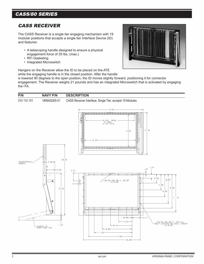
CASS RECEIVERThe CASS Receiver is a single tier engaging mechanism with 19modular positions that accepts a single tier Interface Device (ID) and features:
• A telescoping handle designed to ensure a physical engagement force of 35 lbs. (max.)• RFI Gasketing• Integrated Microswitch
Hangers on the Receiver allow the ID to be placed on the ATE while the engaging handle is in the closed position. After the handleis lowered 90 degrees to the open position, the ID moves slightly forward, positioning it for connector engagement. The Receiver weighs 21 pounds and has an integrated Microswitch that is activated by engaging the ITA.
P/N NAVY P/N DESCRIPTION 310 115 101 1899AS265-01 CASS Receiver Interface, Single Tier, accepts 19 Modules

VIRGINIA PANEL CORPORATION vpc.com 3
CASS/80 SERIES
CASS LIGHTWEIGHT RECEIVERThe 80 Series Lightweight and RTCASS Receivers are designed for use on portable test stations where weight is a major consideration. Weighing only 11 lbs, the Receiver features a single tier engaging mechanism with 19 modular positions, and accepts a single tier Interface Device (ID). A microswitch is integrated into the Receiver and activated by engaging the ID. The Lightweight Receiver includes RFI gasketing but does not have a telescoping handle as specified by the Navy’s CASS guidelines. The RTCASS version has both RFI gasketing as well as a telescoping handle.
P/N DESCRIPTION 310 115 116 80 Series Lightweight Receiver, Single Tier, accepts 19 modules 310 115 119 RTCASS Lightweight Receiver, Single Tier, accepts 19 modules
2.50
3.00
9.750
11.550
.49018 EQ. SPCS. @ .800
14.4001.815
18.03
19.19
SECTION A-A
A
A
4 vpc.com VIRGINIA PANEL CORPORATION
CASS/80 SERIES
80 SERIES RECEIVER
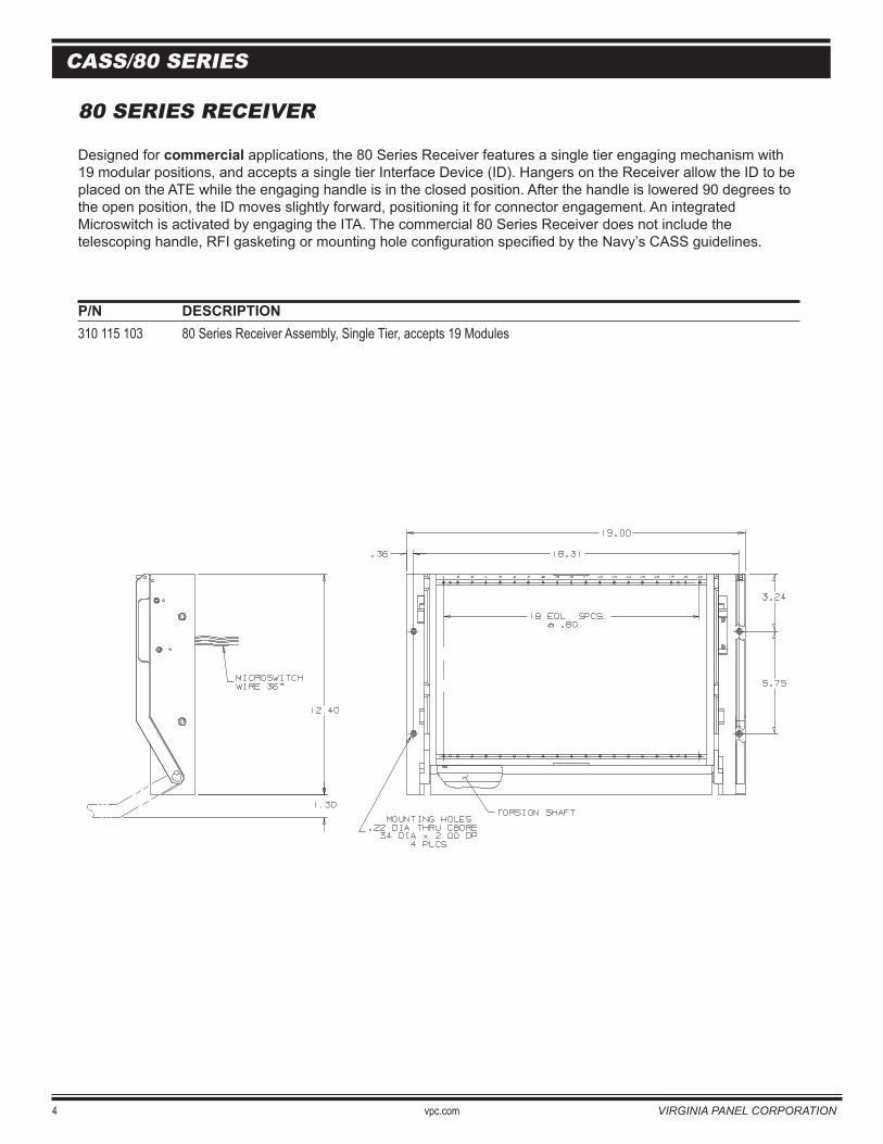
Designed for commercial applications, the 80 Series Receiver features a single tier engaging mechanism with 19 modular positions, and accepts a single tier Interface Device (ID). Hangers on the Receiver allow the ID to be placed on the ATE while the engaging handle is in the closed position. After the handle is lowered 90 degrees to the open position, the ID moves slightly forward, positioning it for connector engagement. An integrated Microswitch is activated by engaging the ITA. The commercial 80 Series Receiver does not include the telescoping handle, RFI gasketing or mounting hole configuration specified by the Navy’s CASS guidelines.
P/N DESCRIPTION 310 115 103 80 Series Receiver Assembly, Single Tier, accepts 19 Modules
VIRGINIA PANEL CORPORATION vpc.com 5
CASS/80 SERIES
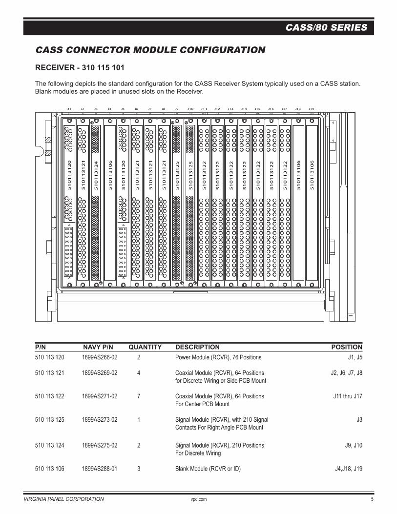
CASS CONNECTOR MODULE CONFIGURATION
RECEIVER - 310 115 101
The following depicts the standard configuration for the CASS Receiver System typically used on a CASS station. Blank modules are placed in unused slots on the Receiver.
P/N NAVY P/N QUANTITY DESCRIPTION POSITION510 113 120 1899AS266-02 2 Power Module (RCVR), 76 Positions J1, J5
510 113 121 1899AS269-02 4 Coaxial Module (RCVR), 64 Positions J2, J6, J7, J8 for Discrete Wiring or Side PCB Mount
510 113 122 1899AS271-02 7 Coaxial Module (RCVR), 64 Positions J11 thru J17 For Center PCB Mount
510 113 125 1899AS273-02 1 Signal Module (RCVR), with 210 Signal J3 Contacts For Right Angle PCB Mount
510 113 124 1899AS275-02 2 Signal Module (RCVR), 210 Positions J9, J10 For Discrete Wiring
510 113 106 1899AS288-01 3 Blank Module (RCVR or ID) J4,J18, J19
RECEIVER 310 115 101
J2 J3 J4 J5 J6 J7 J8 J9 J10 J11 J12 J13 J14 J15 J16 J17 J18 J19J1
51
01
13
12
1
51
01
13
12
0
51
01
13
10
6
51
01
13
12
1
51
01
13
12
1
51
01
13
12
1
51
01
13
12
4
51
01
13
12
0
51
01
13
12
5
51
01
13
12
5
51
01
13
10
6
51
01
13
10
6
51
01
13
12
2
51
01
13
12
2
51
01
13
12
2
51
01
13
12
2
51
01
13
12
2
51
01
13
12
2
51
01
13
12
2
J2J1 J3 J4 J5 J6 J7 J8 J9 J10 J11 J12 J13 J14 J15 J16 J17 J18 J19
6 vpc.com VIRGINIA PANEL CORPORATION
CASS/80 SERIES
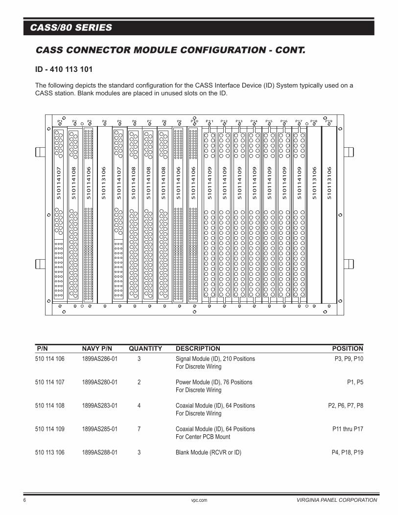
CASS CONNECTOR MODULE CONFIGURATION - CONT.
ID - 410 113 101
The following depicts the standard configuration for the CASS Interface Device (ID) System typically used on a CASS station. Blank modules are placed in unused slots on the ID.
P/N NAVY P/N QUANTITY DESCRIPTION POSITION510 114 106 1899AS286-01 3 Signal Module (ID), 210 Positions P3, P9, P10 For Discrete Wiring
510 114 107 1899AS280-01 2 Power Module (ID), 76 Positions P1, P5 For Discrete Wiring
510 114 108 1899AS283-01 4 Coaxial Module (ID), 64 Positions P2, P6, P7, P8 For Discrete Wiring
510 114 109 1899AS285-01 7 Coaxial Module (ID), 64 Positions P11 thru P17 For Center PCB Mount
510 113 106 1899AS288-01 3 Blank Module (RCVR or ID) P4, P18, P19
P1 P2 P3 P4 P10P5 P6 P7 P8 P9 P11 P12 P13 P14 P15 P16 P17 P18 P19
51
01
14
10
7
51
01
14
10
7
51
01
14
10
8
51
01
14
10
6
51
01
13
10
6
51
01
14
10
6
51
01
14
10
6
51
01
14
10
8
51
01
14
10
8
51
01
14
10
8
51
01
14
10
9
51
01
14
10
9
51
01
14
10
9
51
01
14
10
9
51
01
14
10
9
51
01
14
10
9
51
01
14
10
9
51
01
13
10
6
51
01
13
10
6RECEIVER 410 113 101
VIRGINIA PANEL CORPORATION vpc.com 7
CASS/80 SERIES
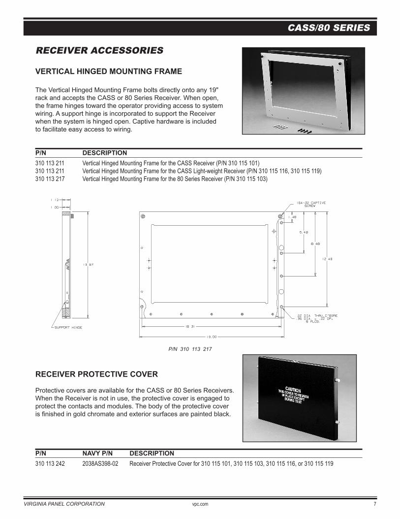
RECEIVER ACCESSORIES
VERTICAL HINGED MOUNTING FRAME
The Vertical Hinged Mounting Frame bolts directly onto any 19" rack and accepts the CASS or 80 Series Receiver. When open, the frame hinges toward the operator providing access to systemwiring. A support hinge is incorporated to support the Receiver when the system is hinged open. Captive hardware is includedto facilitate easy access to wiring.
P/N DESCRIPTION 310 113 211 Vertical Hinged Mounting Frame for the CASS Receiver (P/N 310 115 101)310 113 211 Vertical Hinged Mounting Frame for the CASS Light-weight Receiver (P/N 310 115 116, 310 115 119)310 113 217 Vertical Hinged Mounting Frame for the 80 Series Receiver (P/N 310 115 103)
RECEIVER PROTECTIVE COVER
Protective covers are available for the CASS or 80 Series Receivers.When the Receiver is not in use, the protective cover is engaged toprotect the contacts and modules. The body of the protective coveris finished in gold chromate and exterior surfaces are painted black.
P/N NAVY P/N DESCRIPTION 310 113 242 2038AS398-02 Receiver Protective Cover for 310 115 101, 310 115 103, 310 115 116, or 310 115 119
P/N 310 113 217
8 vpc.com VIRGINIA PANEL CORPORATION
CASS/80 SERIES
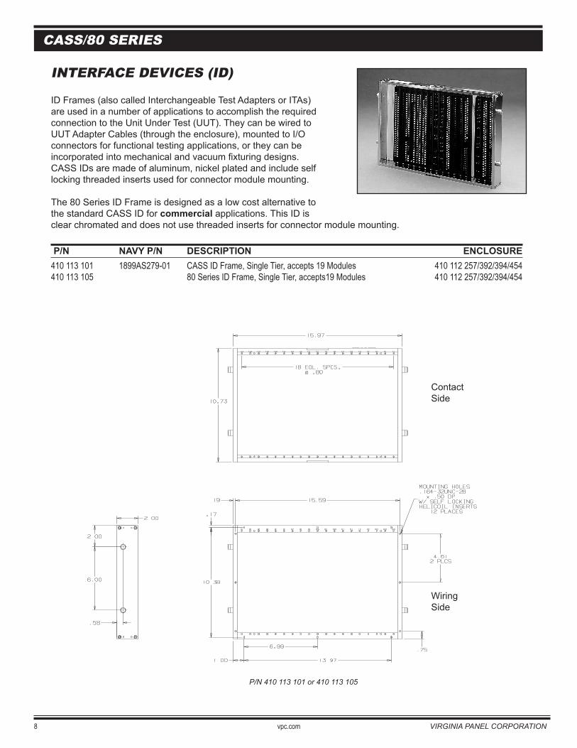
P/N 410 113 101 or 410 113 105
ContactSide
WiringSide
INTERFACE DEVICES (ID)
ID Frames (also called Interchangeable Test Adapters or ITAs)are used in a number of applications to accomplish the requiredconnection to the Unit Under Test (UUT). They can be wired toUUT Adapter Cables (through the enclosure), mounted to I/Oconnectors for functional testing applications, or they can beincorporated into mechanical and vacuum fixturing designs.CASS IDs are made of aluminum, nickel plated and include self locking threaded inserts used for connector module mounting.
The 80 Series ID Frame is designed as a low cost alternative to the standard CASS ID for commercial applications. This ID is clear chromated and does not use threaded inserts for connector module mounting.
P/N NAVY P/N DESCRIPTION ENCLOSURE 410 113 101 1899AS279-01 CASS ID Frame, Single Tier, accepts 19 Modules 410 112 257/392/394/454410 113 105 80 Series ID Frame, Single Tier, accepts19 Modules 410 112 257/392/394/454
CASS/80 SERIES
VIRGINIA PANEL CORPORATION vpc.com 9
CASS/80 SERIES
80 SERIES ID FRAMES
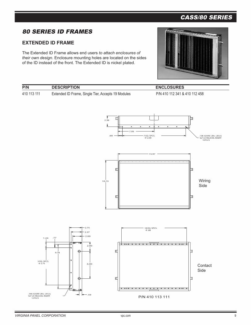
EXTENDED ID FRAME
The Extended ID Frame allows end users to attach enclosures of their own design. Enclosure mounting holes are located on the sides of the ID instead of the front. The Extended ID is nickel plated.
P/N DESCRIPTION ENCLOSURES 410 113 111 Extended ID Frame, Single Tier, Accepts 19 Modules P/N 410 112 341 & 410 112 458
10.73
P1P2P3P4P10 P5P6P7P8P9P11P12P13P14
18 EQ. SPCS. @ .80
P15P16P17P18P19
15.97
P1 P2 P3 P4 P10P5 P6 P7 P8 P9 P11 P12 P13 P14 P15 P16 P17 P18 P19
2.00
2.75
2.00
6.00
1.24 .77
.59
2.38
.138-32UNC-2B x .28 LG SLF LK HELICOIL INSERT 18 PLCS
.99
2.37
9.78
7.99
3 EQ. SPCS. @ 2.75
7 EQ. SPCS. @ 2.00
.190-32UNF-2B x .29 LGSLF LK HELICOIL INSERT 12 PLCS
WiringSide
ContactSide
P/N 410 113 111
ContactSide
WiringSide
10 vpc.com VIRGINIA PANEL CORPORATION
CASS/80 SERIES
80 SERIES ID FRAMES
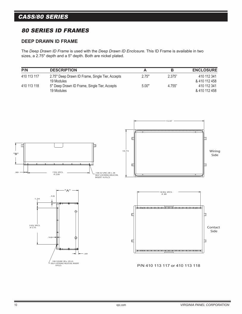
DEEP DRAWN ID FRAME
The Deep Drawn ID Frame is used with the Deep Drawn ID Enclosure. This ID Frame is available in two sizes, a 2.75" depth and a 5" depth. Both are nickel plated.
P/N DESCRIPTION A B ENCLOSURE410 113 117 2.75" Deep Drawn ID Frame, Single Tier, Accepts 2.75" 2.375” 410 112 341 19 Modules & 410 112 458410 113 118 5" Deep Drawn ID Frame, Single Tier, Accepts 5.00" 4.755” 410 112 341 19 Modules & 410 112 458
10.73
P1P2P3P4P10 P5P6P7P8
"A"
P9
18 EQ. SPCS. @ .80
P11
.190-32UNF-2B x .29 LGSELF LOCKING HELICOIL INSERT 8 PLCS
P12P13P14P15P16P17P18P19
15.97
P1 P2 P3 P4 P10P5 P6 P7 P8 P9 P11 P12 P13 P14 P15
"B"
P16 P17 P18 P19
.10
.99 7 EQ. SPCS. @ 2.00
1.24
.59
3 EQ. SPCS. @ 2.75
.10
Contact Side
WiringSide
P/N 410 113 117 or 410 113 118
.138-32 UNC-2B x .28SELF LOCKING HELICOIL INSERT 16 PLCS
VIRGINIA PANEL CORPORATION vpc.com 11
CASS/80 SERIES
CASS KITS
CASS ID FRAME
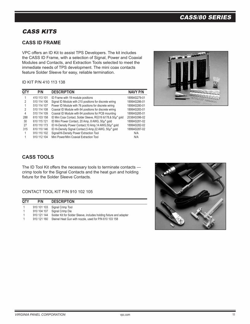
VPC offers an ID Kit to assist TPS Developers. The kit includes the CASS ID Frame, with a selection of Signal, Power and Coaxial Modules and Contacts, and Extraction Tools selected to meet the immediate needs of TPS development. The mini coax contactsfeature Solder Sleeve for easy, reliable termination.
ID KIT P/N 410 113 138
QTY P/N DESCRIPTION NAVY P/N 1 410 113 101 ID Frame with 19 module positions 1899AS279-01 2 510 114 106 Signal ID Module with 210 positions for discrete wiring 1899AS286-01 1 510 114 107 Power ID Module with 76 positions for discrete wiring 1899AS280-01 2 510 114 108 Coaxial ID Module with 64 positions for discrete wiring 1899AS283-01 4 510 114 109 Coaxial ID Module with 64 positions for PCB mounting 1899AS285-01 288 610 103 158 ID Mini Coax Contact, Solder Sleeve, RG316 &178,& 50µ″ gold 2038AS396-02 30 610 115 121 ID Mini Power Contact, 20 Amp, 8 AWG, 50µ″ gold 1899AS281-02 27 610 110 173 ID Hi-Density Power Contact,10 Amp,14 AWG,50µ″ gold 1899AS282-02 315 610 110 146 ID Hi-Density Signal Contact,5 Amp,22 AWG, 50µ″ gold 1899AS287-02 1 910 110 102 Signal/Hi-Density Power Extraction Tool N/A 1 910 112 104 Mini Power/Mini Coaxial Extraction Tool N/A
CASS TOOLS
The ID Tool Kit offers the necessary tools to terminate contacts —crimp tools for the Signal Contacts and the heat gun and holding fixture for the Solder Sleeve Contacts.
CONTACT TOOL KIT P/N 910 102 105
QTY P/N DESCRIPTION 1 910 101 103 Signal Crimp Tool 1 910 104 107 Signal Crimp Die 1 910 121 144 Solder Kit for Solder Sleeve, includes holding fixture and adapter 1 910 121 160 Steinel Heat Gun with nozzle, used for P/N 610 103 158
12 vpc.com VIRGINIA PANEL CORPORATION
CASS/80 SERIES
ID COVERS AND ENCLOSURES
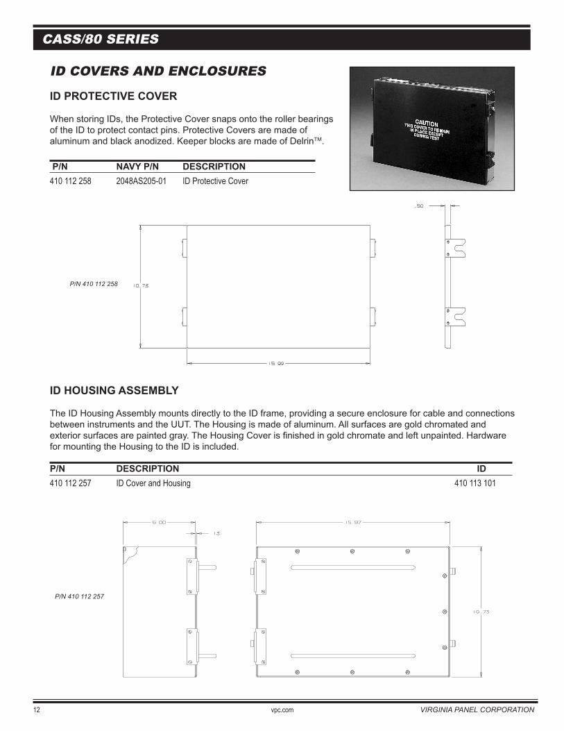
ID PROTECTIVE COVER
When storing IDs, the Protective Cover snaps onto the roller bearingsof the ID to protect contact pins. Protective Covers are made of aluminum and black anodized. Keeper blocks are made of DelrinTM.
P/N NAVY P/N DESCRIPTION 410 112 258 2048AS205-01 ID Protective Cover
P/N 410 112 258
P/N 410 112 257
ID HOUSING ASSEMBLY
The ID Housing Assembly mounts directly to the ID frame, providing a secure enclosure for cable and connections between instruments and the UUT. The Housing is made of aluminum. All surfaces are gold chromated and exterior surfaces are painted gray. The Housing Cover is finished in gold chromate and left unpainted. Hardware for mounting the Housing to the ID is included.
P/N DESCRIPTION ID 410 112 257 ID Cover and Housing 410 113 101
P/N 410 112 258
P/N 410 112 257
VIRGINIA PANEL CORPORATION vpc.com 13
CASS/80 SERIES & 410 113 105 ID COVERS AND ENCLOSURES
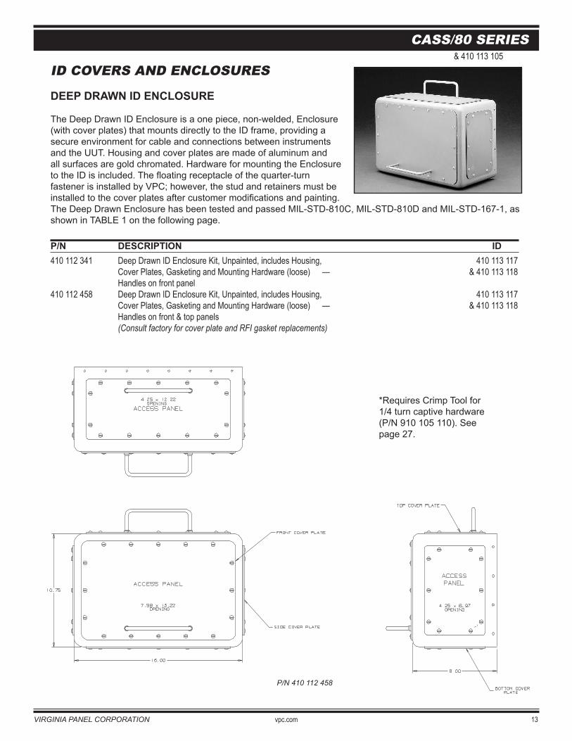
DEEP DRAWN ID ENCLOSURE
The Deep Drawn ID Enclosure is a one piece, non-welded, Enclosure(with cover plates) that mounts directly to the ID frame, providing a secure environment for cable and connections between instrumentsand the UUT. Housing and cover plates are made of aluminum andall surfaces are gold chromated. Hardware for mounting the Enclosureto the ID is included. The floating receptacle of the quarter-turn fastener is installed by VPC; however, the stud and retainers must beinstalled to the cover plates after customer modifications and painting.The Deep Drawn Enclosure has been tested and passed MIL-STD-810C, MIL-STD-810D and MIL-STD-167-1, as shown in TABLE 1 on the following page.
P/N DESCRIPTION ID 410 112 341 Deep Drawn ID Enclosure Kit, Unpainted, includes Housing, 410 113 117 Cover Plates, Gasketing and Mounting Hardware (loose) — & 410 113 118 Handles on front panel410 112 458 Deep Drawn ID Enclosure Kit, Unpainted, includes Housing, 410 113 117 Cover Plates, Gasketing and Mounting Hardware (loose) — & 410 113 118 Handles on front & top panels (Consult factory for cover plate and RFI gasket replacements)
P/N 410 112 458
*Requires Crimp Tool for 1/4 turn captive hardware (P/N 910 105 110). See page 27.
14 vpc.com VIRGINIA PANEL CORPORATION
CASS/80 SERIES
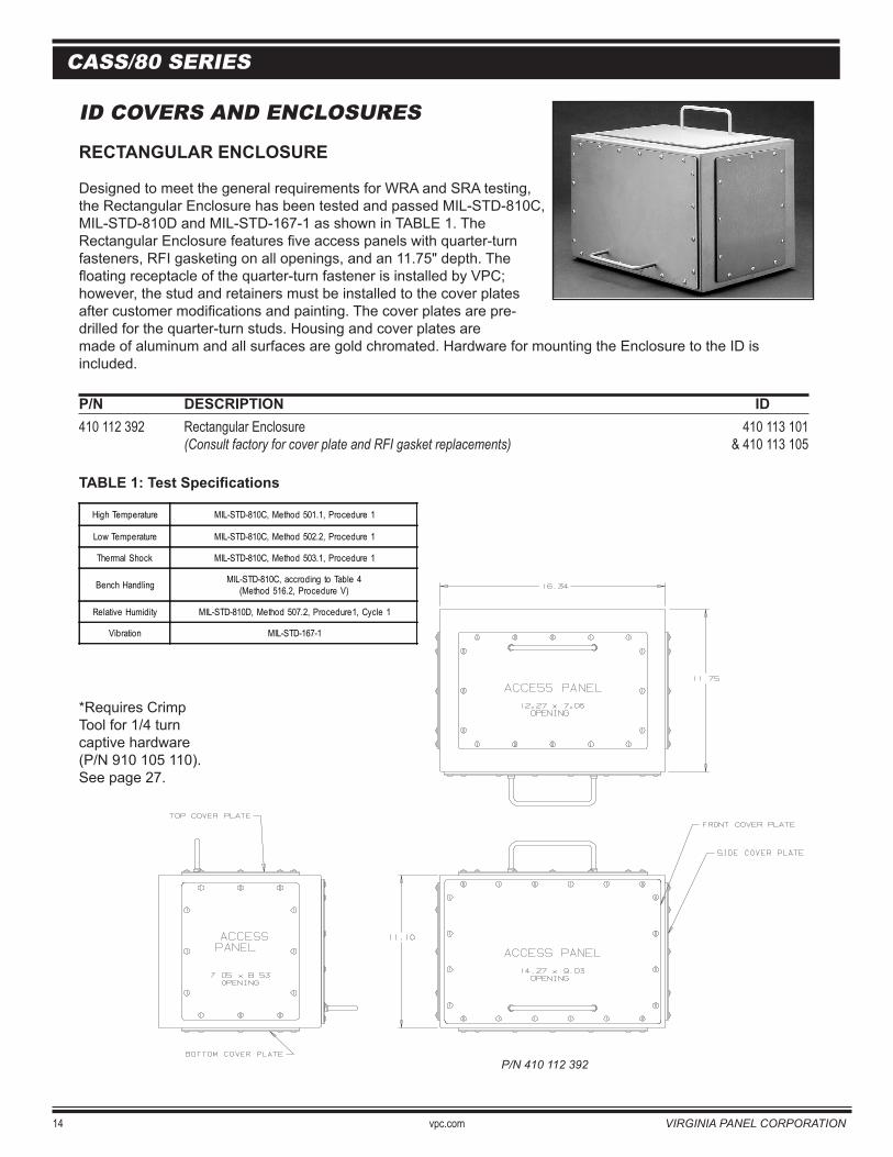
P/N 410 112 392
*Requires Crimp Tool for 1/4 turn captive hardware (P/N 910 105 110). See page 27.
TABLE 1: Test Specifications
ID COVERS AND ENCLOSURES
RECTANGULAR ENCLOSURE
Designed to meet the general requirements for WRA and SRA testing,the Rectangular Enclosure has been tested and passed MIL-STD-810C,MIL-STD-810D and MIL-STD-167-1 as shown in TABLE 1. The Rectangular Enclosure features five access panels with quarter-turnfasteners, RFI gasketing on all openings, and an 11.75" depth. Thefloating receptacle of the quarter-turn fastener is installed by VPC; however, the stud and retainers must be installed to the cover platesafter customer modifications and painting. The cover plates are pre-drilled for the quarter-turn studs. Housing and cover plates are made of aluminum and all surfaces are gold chromated. Hardware for mounting the Enclosure to the ID is included.
P/N DESCRIPTION ID 410 112 392 Rectangular Enclosure 410 113 101 (Consult factory for cover plate and RFI gasket replacements) & 410 113 105
High Temperature MIL-STD-810C, Method 501.1, Procedure 1
Low Temperature MIL-STD-810C, Method 502.2, Procedure 1
Thermal Shock MIL-STD-810C, Method 503.1, Procedure 1
Bench Handling MIL-STD-810C, accroding to Table 4(Method 516.2, Procedure V)
Relative Humidity MIL-STD-810D, Method 507.2, Procedure1, Cycle 1
Vibration MIL-STD-167-1
VIRGINIA PANEL CORPORATION vpc.com 15
CASS/80 SERIES
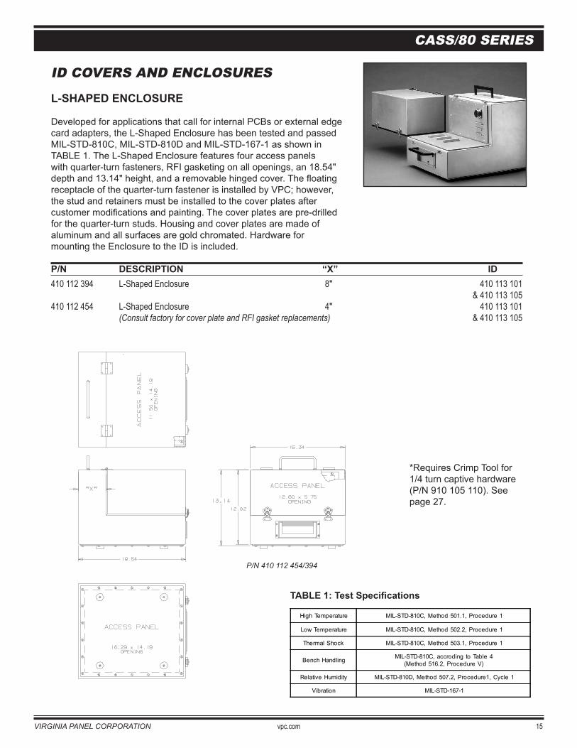
*Requires Crimp Tool for 1/4 turn captive hardware (P/N 910 105 110). See page 27.
High Temperature MIL-STD-810C, Method 501.1, Procedure 1
Low Temperature MIL-STD-810C, Method 502.2, Procedure 1
Thermal Shock MIL-STD-810C, Method 503.1, Procedure 1
Bench Handling MIL-STD-810C, accroding to Table 4(Method 516.2, Procedure V)
Relative Humidity MIL-STD-810D, Method 507.2, Procedure1, Cycle 1
Vibration MIL-STD-167-1
TABLE 1: Test Specifications
ID COVERS AND ENCLOSURES
L-SHAPED ENCLOSURE
Developed for applications that call for internal PCBs or external edge card adapters, the L-Shaped Enclosure has been tested and passedMIL-STD-810C, MIL-STD-810D and MIL-STD-167-1 as shown inTABLE 1. The L-Shaped Enclosure features four access panelswith quarter-turn fasteners, RFI gasketing on all openings, an 18.54"depth and 13.14" height, and a removable hinged cover. The floatingreceptacle of the quarter-turn fastener is installed by VPC; however,the stud and retainers must be installed to the cover plates aftercustomer modifications and painting. The cover plates are pre-drilledfor the quarter-turn studs. Housing and cover plates are made of aluminum and all surfaces are gold chromated. Hardware formounting the Enclosure to the ID is included.
P/N DESCRIPTION “X” ID 410 112 394 L-Shaped Enclosure 8" 410 113 101 & 410 113 105410 112 454 L-Shaped Enclosure 4" 410 113 101 (Consult factory for cover plate and RFI gasket replacements) & 410 113 105
P/N 410 112 454/394
P/N 410 112 454/394
16 vpc.com VIRGINIA PANEL CORPORATION
CASS/80 SERIES
CONNECTOR MODULES
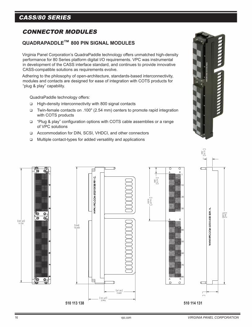
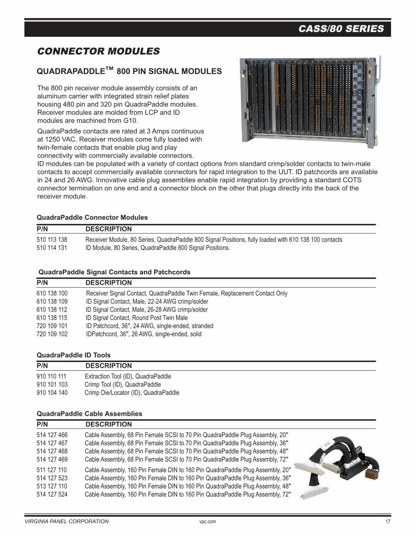
QUADRAPADDLETM 800 PIN SIGNAL MODULES
Virginia Panel Corporation’s QuadraPaddle technology offers unmatched high-density performance for 80 Series platform digital I/O requirements. VPC was instrumental in development of the CASS interface standard, and continues to provide innovative CASS-compatible solutions as requirements evolve.Adhering to the philosophy of open-architecture, standards-based interconnectivity, modules and contacts are designed for ease of integration with COTS products for “plug & play” capability.
QuadraPaddle technology offers: High-density interconnectivity with 800 signal contacts Twin-female contacts on .100" (2.54 mm) centers to promote rapid integration
with COTS products “Plug & play” configuration options with COTS cable assemblies or a range
of VPC solutions Accommodation for DIN, SCSI, VHDCI, and other connectors Multiple contact-types for added versatility and applications
510 113 138 510 114 131
.80020.32
9.750247.65
1.59040.39
.58014.73
4.605116.97
.99325.22
.50012.70
10.000254
A K
A K
A K
1
10
20
30
40
50
60
70
80
9.750247.65
25410.000
3.995101.47
2.66067.56
VIRGINIA PANEL CORPORATION vpc.com 17
CASS/80 SERIES
CONNECTOR MODULES
QUADRAPADDLETM 800 PIN SIGNAL MODULES
The 800 pin receiver module assembly consists of an aluminum carrier with integrated strain relief plates housing 480 pin and 320 pin QuadraPaddle modules. Receiver modules are molded from LCP and ID modules are machined from G10. QuadraPaddle contacts are rated at 3 Amps continuous at 1250 VAC. Receiver modules come fully loaded with twin-female contacts that enable plug and play connectivity with commercially available connectors. ID modules can be populated with a variety of contact options from standard crimp/solder contacts to twin-male contacts to accept commercially available connectors for rapid integration to the UUT. ID patchcords are available in 24 and 26 AWG. Innovative cable plug assemblies enable rapid integration by providing a standard COTS connector termination on one end and a connector block on the other that plugs directly into the back of the receiver module.
QuadraPaddle Connector ModulesP/N DESCRIPTION 510 113 138 Receiver Module, 80 Series, QuadraPaddle 800 Signal Positions, fully loaded with 610 138 100 contacts510 114 131 ID Module, 80 Series, QuadraPaddle 800 Signal Positions.
QuadraPaddle Signal Contacts and PatchcordsP/N DESCRIPTION 610 138 100 Receiver Signal Contact, QuadraPaddle Twin Female, Replacement Contact Only 610 138 109 ID Signal Contact, Male, 22-24 AWG crimp/solder 610 138 112 ID Signal Contact, Male, 26-28 AWG crimp/solder 610 138 115 ID Signal Contact, Round Post Twin Male 720 109 101 ID Patchcord, 36", 24 AWG, single-ended, stranded 720 109 102 IDPatchcord, 36", 26 AWG, single-ended, solid
QuadraPaddle ID ToolsP/N DESCRIPTION 910 110 111 Extraction Tool (ID), QuadraPaddle 910 101 103 Crimp Tool (ID), QuadraPaddle 910 104 140 Crimp Die/Locator (ID), QuadraPaddle
QuadraPaddle Cable AssembliesP/N DESCRIPTION 514 127 466 Cable Assembly, 68 Pin Female SCSI to 70 Pin QuadraPaddle Plug Assembly, 20" 514 127 467 Cable Assembly, 68 Pin Female SCSI to 70 Pin QuadraPaddle Plug Assembly, 36" 514 127 468 Cable Assembly, 68 Pin Female SCSI to 70 Pin QuadraPaddle Plug Assembly, 48" 514 127 469 Cable Assembly, 68 Pin Female SCSI to 70 Pin QuadraPaddle Plug Assembly, 72"511 127 110 Cable Assembly, 160 Pin Female DIN to 160 Pin QuadraPaddle Plug Assembly, 20" 514 127 523 Cable Assembly, 160 Pin Female DIN to 160 Pin QuadraPaddle Plug Assembly, 36" 513 127 110 Cable Assembly, 160 Pin Female DIN to 160 Pin QuadraPaddle Plug Assembly, 48" 514 127 524 Cable Assembly, 160 Pin Female DIN to 160 Pin QuadraPaddle Plug Assembly, 72"
18 vpc.com VIRGINIA PANEL CORPORATION
CASS/80 SERIES
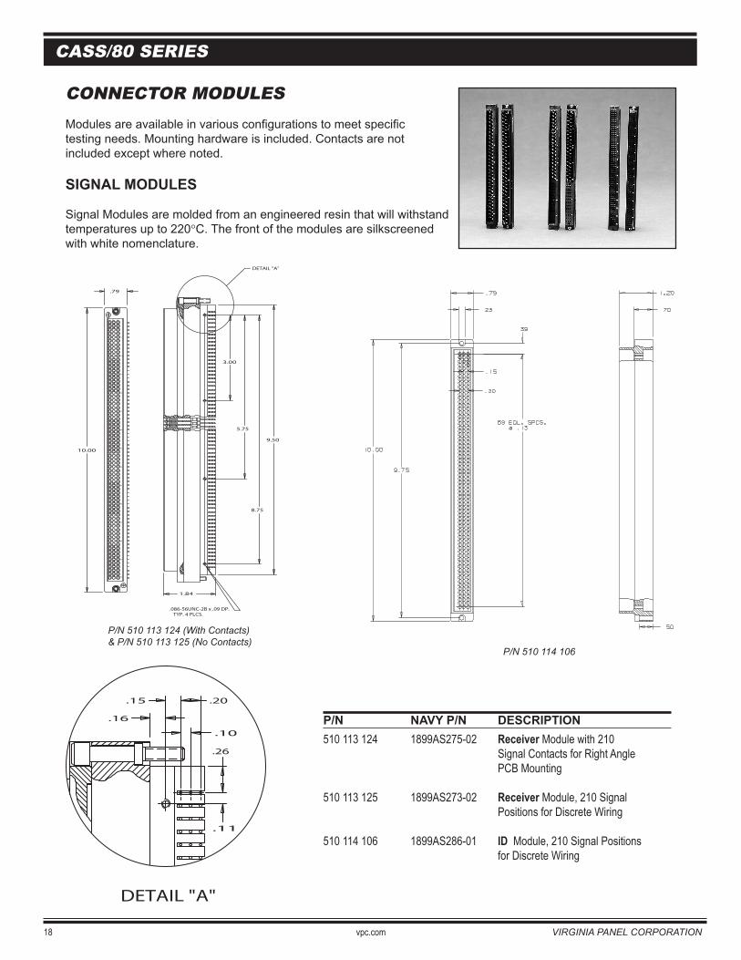
CONNECTOR MODULESModules are available in various configurations to meet specific testing needs. Mounting hardware is included. Contacts are not included except where noted.
SIGNAL MODULES
Signal Modules are molded from an engineered resin that will withstand temperatures up to 220°C. The front of the modules are silkscreenedwith white nomenclature.
P/N NAVY P/N DESCRIPTION 510 113 124 1899AS275-02 Receiver Module with 210 Signal Contacts for Right Angle PCB Mounting
510 113 125 1899AS273-02 Receiver Module, 210 Signal Positions for Discrete Wiring
510 114 106 1899AS286-01 ID Module, 210 Signal Positions for Discrete Wiring
P/N 510 114 106
P/N 510 113 124 (With Contacts)& P/N 510 113 125 (No Contacts)
.16
.20.15
.10
.26
.11
DETAIL "A"
P/N 510 113 124 (With Contacts)& P/N 510 113 125 (No Contacts)
10.00
.79
9.50
5
10
15
A B C
70
20
25
30
35
40
45
50
55
60
65
3.00
5.75
DETAIL "A"
8.75
.086-56UNC-2B x .09 DP. TYP. 4 PLCS.
1.84
P/N 510 114 106
VIRGINIA PANEL CORPORATION vpc.com 19
CASS/80 SERIES
P/N 510 114 107
CONNECTOR MODULES
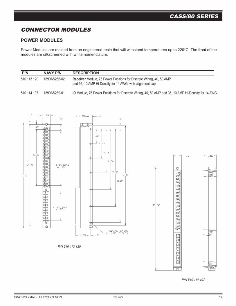
POWER MODULES
Power Modules are molded from an engineered resin that will withstand temperatures up to 220°C. The front of the modules are silkscreened with white nomenclature.
P/N NAVY P/N DESCRIPTION 510 113 120 1899AS266-02 Receiver Module, 76 Power Positions for Discrete Wiring, 40, 50 AMP and 36, 10 AMP Hi-Density for 14 AWG, with alignment cap
510 114 107 1899AS280-01 ID Module, 76 Power Positions for Discrete Wiring, 40, 50 AMP and 36, 10 AMP Hi-Density for 14 AWG
P/N 510 113 120
P/N 510 113 120
P/N 510 114 107
20 vpc.com VIRGINIA PANEL CORPORATION
CASS/80 SERIES
CONNECTOR MODULES
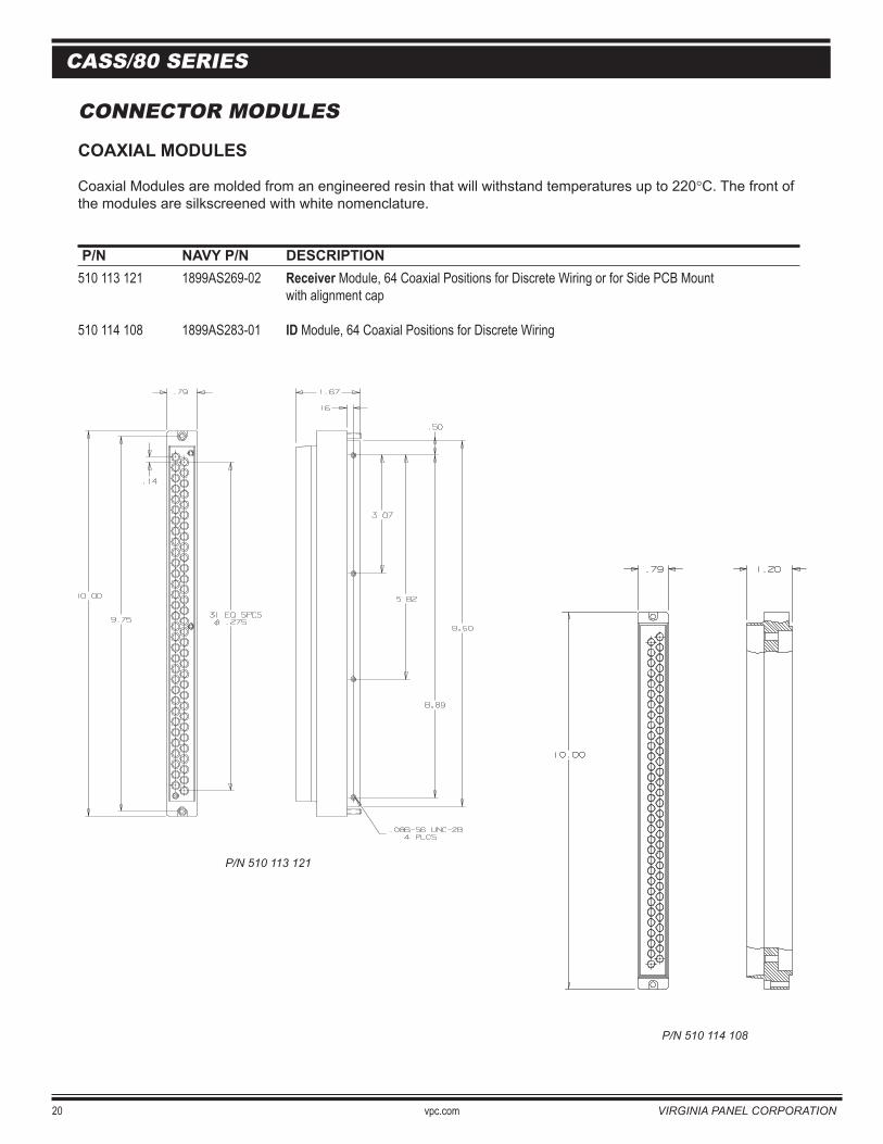
COAXIAL MODULES
Coaxial Modules are molded from an engineered resin that will withstand temperatures up to 220°C. The front of the modules are silkscreened with white nomenclature.
P/N NAVY P/N DESCRIPTION 510 113 121 1899AS269-02 Receiver Module, 64 Coaxial Positions for Discrete Wiring or for Side PCB Mount with alignment cap
510 114 108 1899AS283-01 ID Module, 64 Coaxial Positions for Discrete Wiring
P/N 510 113 121
P/N 510 114 108
P/N 510 113 121
P/N 510 114 108
VIRGINIA PANEL CORPORATION vpc.com 21
CASS/80 SERIES
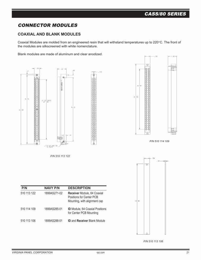
P/N NAVY P/N DESCRIPTION 510 113 122 1899AS271-02 Receiver Module, 64 Coaxial Positions for Center PCB Mounting, with alignment cap
510 114 109 1899AS285-01 ID Module, 64 Coaxial Positions for Center PCB Mounting
510 113 106 1899AS288-01 ID and Receiver Blank Module
CONNECTOR MODULES
COAXIAL AND BLANK MODULES
Coaxial Modules are molded from an engineered resin that will withstand temperatures up to 220°C. The front of the modules are silkscreened with white nomenclature.
Blank modules are made of aluminum and clear anodized.
P/N 510 114 109
P/N 510 113 106
P/N 510 113 122
P/N 510 113 122
P/N 510 114 109
P/N 510 113 106
22 vpc.com VIRGINIA PANEL CORPORATION
CASS/80 SERIES
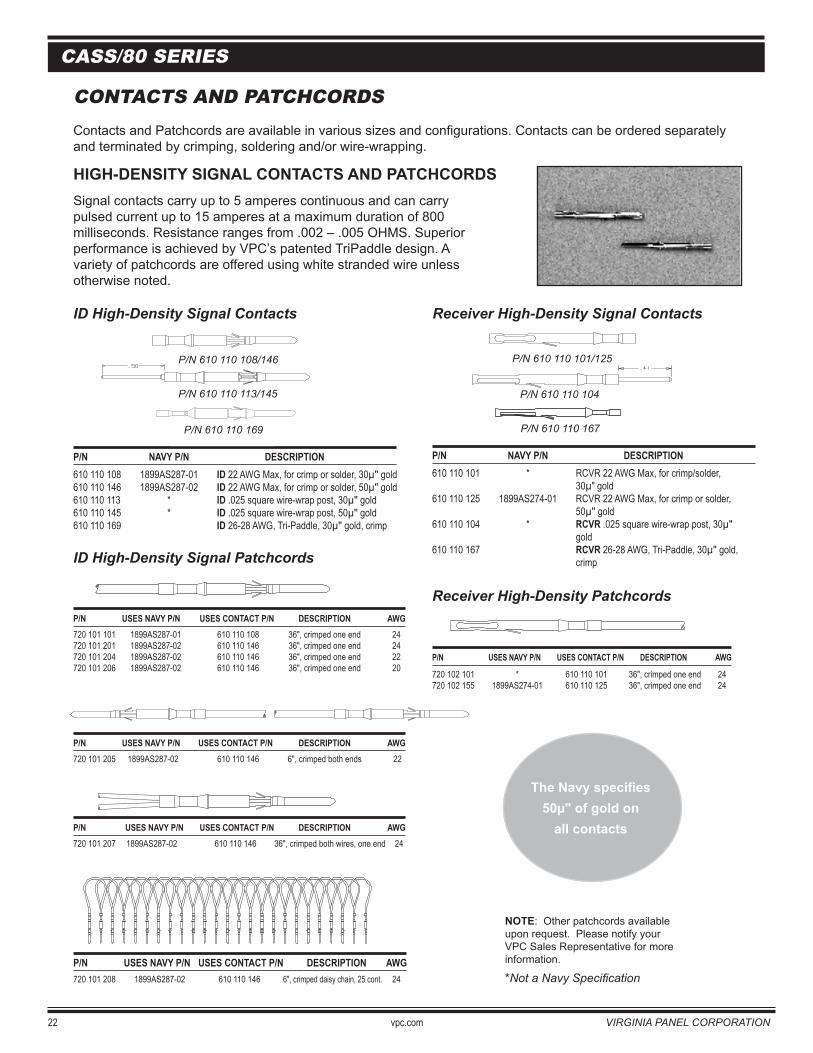
CONTACTS AND PATCHCORDSContacts and Patchcords are available in various sizes and configurations. Contacts can be ordered separately and terminated by crimping, soldering and/or wire-wrapping.
HIGH-DENSITY SIGNAL CONTACTS AND PATCHCORDSSignal contacts carry up to 5 amperes continuous and can carry pulsed current up to 15 amperes at a maximum duration of 800 milliseconds. Resistance ranges from .002 – .005 OHMS. Superiorperformance is achieved by VPC’s patented TriPaddle design. A variety of patchcords are offered using white stranded wire unlessotherwise noted.
ID High-Density Signal Contacts Receiver High-Density Signal Contacts
P/N NAVY P/N DESCRIPTION 610 110 108 1899AS287-01 ID 22 AWG Max, for crimp or solder, 30µ" gold610 110 146 1899AS287-02 ID 22 AWG Max, for crimp or solder, 50µ" gold610 110 113 * ID .025 square wire-wrap post, 30µ" gold610 110 145 * ID .025 square wire-wrap post, 50µ" gold 610 110 169 ID 26-28 AWG, Tri-Paddle, 30µ" gold, crimp
ID High-Density Signal Patchcords
P/N USES NAVY P/N USES CONTACT P/N DESCRIPTION AWG720 101 101 1899AS287-01 610 110 108 36", crimped one end 24720 101 201 1899AS287-02 610 110 146 36", crimped one end 24720 101 204 1899AS287-02 610 110 146 36", crimped one end 22720 101 206 1899AS287-02 610 110 146 36", crimped one end 20
P/N USES NAVY P/N USES CONTACT P/N DESCRIPTION AWG720 101 205 1899AS287-02 610 110 146 6", crimped both ends 22
P/N USES NAVY P/N USES CONTACT P/N DESCRIPTION AWG720 101 207 1899AS287-02 610 110 146 36", crimped both wires, one end 24
P/N USES NAVY P/N USES CONTACT P/N DESCRIPTION AWG720 101 208 1899AS287-02 610 110 146 6", crimped daisy chain, 25 cont. 24
P/N 610 110 108/146
P/N 610 110 113/145
P/N 610 110 169
NOTE: Other patchcords available upon request. Please notify your VPC Sales Representative for more information.
*Not a Navy Specification
The Navy specifies50µ" of gold on
all contacts
P/N 610 110 167
P/N 610 110 104
P/N 610 110 101/125
P/N NAVY P/N DESCRIPTION 610 110 101 * RCVR 22 AWG Max, for crimp/solder, 30µ" gold610 110 125 1899AS274-01 RCVR 22 AWG Max, for crimp or solder, 50µ" gold610 110 104 * RCVR .025 square wire-wrap post, 30µ" gold610 110 167 RCVR 26-28 AWG, Tri-Paddle, 30µ" gold, crimp
P/N USES NAVY P/N USES CONTACT P/N DESCRIPTION AWG
720 102 101 * 610 110 101 36", crimped one end 24720 102 155 1899AS274-01 610 110 125 36", crimped one end 24
Receiver High-Density Patchcords
P/N 610 110 108/146
P/N 610 110 113/145
P/N 610 110 169
P/N 610 110 101/125
P/N 610 110 104
P/N 610 110 167
VIRGINIA PANEL CORPORATION vpc.com 23
CASS/80 SERIES
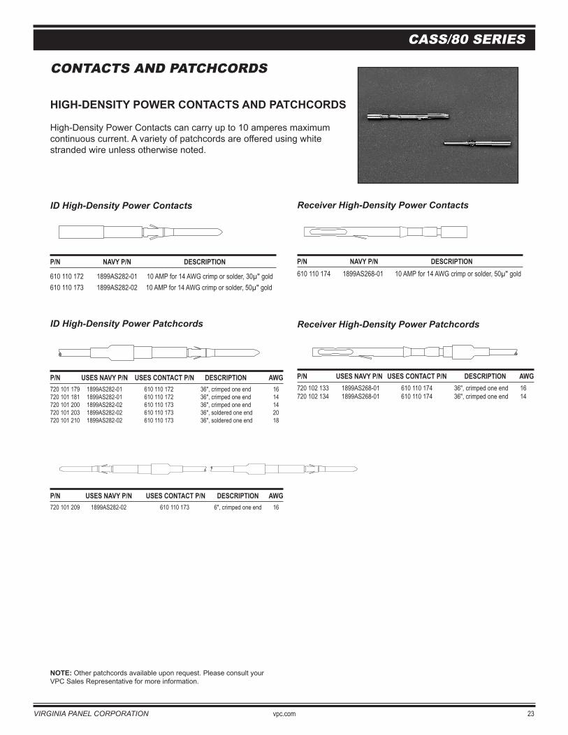
CONTACTS AND PATCHCORDS
HIGH-DENSITY POWER CONTACTS AND PATCHCORDS
High-Density Power Contacts can carry up to 10 amperes maximumcontinuous current. A variety of patchcords are offered using white stranded wire unless otherwise noted.
ID High-Density Power Contacts
P/N NAVY P/N DESCRIPTION
610 110 172 1899AS282-01 10 AMP for 14 AWG crimp or solder, 30µ" gold610 110 173 1899AS282-02 10 AMP for 14 AWG crimp or solder, 50µ" gold
ID High-Density Power Patchcords
P/N USES NAVY P/N USES CONTACT P/N DESCRIPTION AWG720 101 179 1899AS282-01 610 110 172 36", crimped one end 16720 101 181 1899AS282-01 610 110 172 36", crimped one end 14720 101 200 1899AS282-02 610 110 173 36", crimped one end 14720 101 203 1899AS282-02 610 110 173 36", soldered one end 20720 101 210 1899AS282-02 610 110 173 36", soldered one end 18
P/N USES NAVY P/N USES CONTACT P/N DESCRIPTION AWG720 101 209 1899AS282-02 610 110 173 6", crimped one end 16
NOTE: Other patchcords available upon request. Please consult your VPC Sales Representative for more information.
Receiver High-Density Power Contacts
P/N NAVY P/N DESCRIPTION 610 110 174 1899AS268-01 10 AMP for 14 AWG crimp or solder, 50µ" gold
Receiver High-Density Power Patchcords
P/N USES NAVY P/N USES CONTACT P/N DESCRIPTION AWG720 102 133 1899AS268-01 610 110 174 36", crimped one end 16720 102 134 1899AS268-01 610 110 174 36", crimped one end 14
24 vpc.com VIRGINIA PANEL CORPORATION
CASS/80 SERIES
CONTACTS AND PATCHCORDS
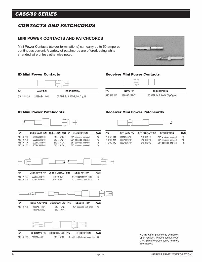
MINI POWER CONTACTS AND PATCHCORDS
Mini Power Contacts (solder terminations) can carry up to 50 amperes continuous current. A variety of patchcords are offered, using whitestranded wire unless otherwise noted.
ID Mini Power Contacts Receiver Mini Power Contacts
P/N NAVY P/N DESCRIPTION
610 115 124 2038AS418-01 50 AMP for 8 AWG, 50µ" gold
ID Mini Power Patchcords Receiver Mini Power Patchcords
P/N USES NAVY P/N USES CONTACT P/N DESCRIPTION AWG716 101 172 2038AS418-01 610 115 124 36", soldered one end 12716 101 175 2038AS418-01 610 115 124 36", soldered one end 16716 101 176 2038AS418-01 610 115 124 36", soldered one end 8716 101 177 2038AS418-01 610 115 124 36", soldered one end 20
P/N USES NAVY P/N USES CONTACT P/N DESCRIPTION AWG716 101 173 2038AS418-01 610 115 124 6", soldered both ends 16716 101 174 2038AS418-01 610 115 124 10", soldered both ends 16
P/N USES NAVY P/N USES CONTACT P/N DESCRIPTION AWG716 101 178 2038AS418-01 610 115 124 10", soldered both ends 16 1899AS282-02 610 110 147
P/N USES NAVY P/N USES CONTACT P/N DESCRIPTION AWG716 101 179 2038AS418-01 610 115 123 6", soldered both wires one end 22
P/N NAVY P/N DESCRIPTION 610 116 112 1899AS267-01 50 AMP for 8 AWG, 50µ" gold
NOTE: Other patchcords available upon request. Please consult your VPC Sales Representative for more information.
P/N USES NAVY P/N USES CONTACT P/N DESCRIPTION AWG716 102 122 1899AS267-01 610 116 112 36", soldered one end 12716 102 141 1899AS267-01 610 116 112 36", soldered one end 16716 102 142 1899AS267-01 610 116 112 36", soldered one end 8
VIRGINIA PANEL CORPORATION vpc.com 25
CASS/80 SERIES
CONTACTS AND PATCHCORDS
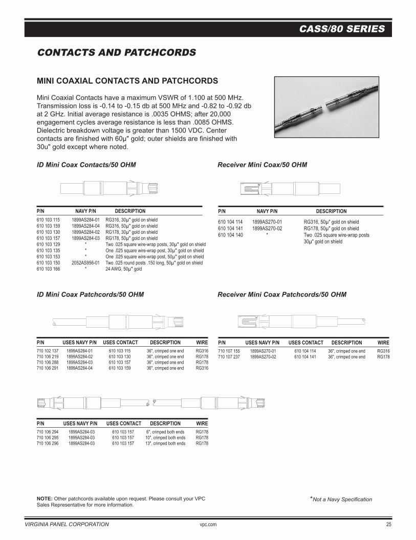
MINI COAXIAL CONTACTS AND PATCHCORDS
Mini Coaxial Contacts have a maximum VSWR of 1.100 at 500 MHz. Transmission loss is -0.14 to -0.15 db at 500 MHz and -0.82 to -0.92 db at 2 GHz. Initial average resistance is .0035 OHMS; after 20,000 engagement cycles average resistance is less than .0085 OHMS. Dielectric breakdown voltage is greater than 1500 VDC. Center contacts are finished with 60µ" gold; outer shields are finished with 30u" gold except where noted.
ID Mini Coax Contacts/50 OHM Receiver Mini Coax/50 OHM
P/N NAVY P/N DESCRIPTION 610 103 115 1899AS284-01 RG316, 30µ" gold on shield610 103 159 1899AS284-04 RG316, 50µ" gold on shield 610 103 130 1899AS284-02 RG178, 30µ" gold on shield610 103 157 1899AS284-03 RG178, 50µ" gold on shield610 103 129 * Two .025 square wire-wrap posts, 30µ" gold on shield610 103 135 * One .025 square wire-wrap post, 30µ" gold on shield610 103 153 * One .025 square wire-wrap post, 50µ" gold on shield610 103 150 2052AS956-01 Two .025 round posts .150 long, 50µ" gold on shield610 103 166 * 24 AWG, 50µ" gold
ID Mini Coax Patchcords/50 OHM Receiver Mini Coax Patchcords/50 OHM
P/N USES NAVY P/N USES CONTACT DESCRIPTION WIRE 710 102 137 1899AS284-01 610 103 115 36", crimped one end RG316710 106 219 1899AS284-02 610 103 130 36", crimped one end RG178710 106 288 1899AS284-03 610 103 157 36", crimped one end RG178710 106 291 1899AS284-04 610 103 159 36", crimped one end RG316
P/N USES NAVY P/N USES CONTACT DESCRIPTION WIRE710 106 294 1899AS284-03 610 103 157 6", crimped both ends RG178710 106 295 1899AS284-03 610 103 157 10", crimped both ends RG178710 106 296 1899AS284-03 610 103 157 13", crimped both ends RG178
NOTE: Other patchcords available upon request. Please consult your VPC Sales Representative for more information.
*Not a Navy Specification
P/N NAVY P/N DESCRIPTION
610 104 114 1899AS270-01 RG316, 50µ" gold on shield610 104 141 1899AS270-02 RG178, 50µ" gold on shield 610 104 140 * Two .025 square wire-wrap posts 30µ" gold on shield
P/N USES NAVY P/N USES CONTACT DESCRIPTION WIRE710 107 155 1899AS270-01 610 104 114 36", crimped one end RG316710 107 237 1899AS270-02 610 104 141 36", crimped one end RG178
26 vpc.com VIRGINIA PANEL CORPORATION
CASS/80 SERIES
CONTACTS AND PATCHCORDS
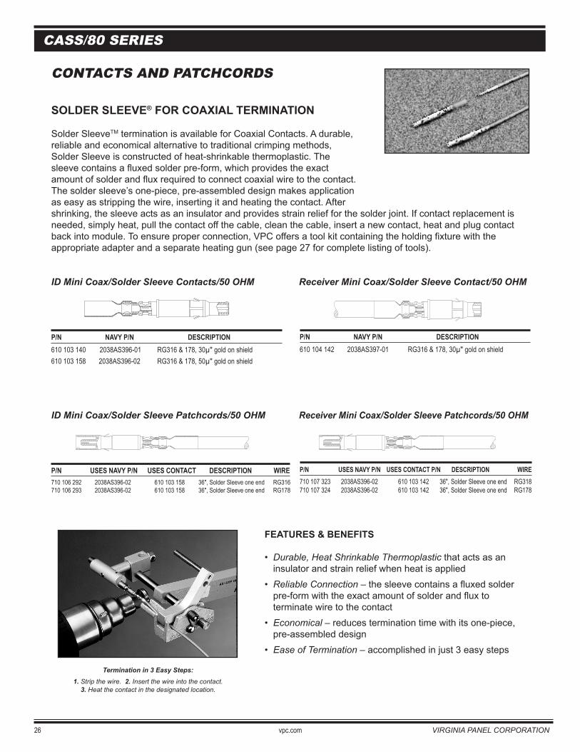
SOLDER SLEEVE® FOR COAXIAL TERMINATION
Solder SleeveTM termination is available for Coaxial Contacts. A durable,reliable and economical alternative to traditional crimping methods, Solder Sleeve is constructed of heat-shrinkable thermoplastic. Thesleeve contains a fluxed solder pre-form, which provides the exact amount of solder and flux required to connect coaxial wire to the contact.The solder sleeve’s one-piece, pre-assembled design makes applicationas easy as stripping the wire, inserting it and heating the contact. After shrinking, the sleeve acts as an insulator and provides strain relief for the solder joint. If contact replacement is needed, simply heat, pull the contact off the cable, clean the cable, insert a new contact, heat and plug contact back into module. To ensure proper connection, VPC offers a tool kit containing the holding fixture with the appropriate adapter and a separate heating gun (see page 27 for complete listing of tools).
ID Mini Coax/Solder Sleeve Contacts/50 OHM Receiver Mini Coax/Solder Sleeve Contact/50 OHM
P/N NAVY P/N DESCRIPTION 610 103 140 2038AS396-01 RG316 & 178, 30µ" gold on shield610 103 158 2038AS396-02 RG316 & 178, 50µ" gold on shield
ID Mini Coax/Solder Sleeve Patchcords/50 OHM Receiver Mini Coax/Solder Sleeve Patchcords/50 OHM
P/N USES NAVY P/N USES CONTACT DESCRIPTION WIRE710 106 292 2038AS396-02 610 103 158 36", Solder Sleeve one end RG316710 106 293 2038AS396-02 610 103 158 36", Solder Sleeve one end RG178
P/N NAVY P/N DESCRIPTION 610 104 142 2038AS397-01 RG316 & 178, 30µ" gold on shield
FEATURES & BENEFITS
• Durable, Heat Shrinkable Thermoplastic that acts as an insulator and strain relief when heat is applied
• Reliable Connection – the sleeve contains a fluxed solder pre-form with the exact amount of solder and flux to terminate wire to the contact
• Economical – reduces termination time with its one-piece, pre-assembled design
• Ease of Termination – accomplished in just 3 easy steps
Termination in 3 Easy Steps:1. Strip the wire. 2. Insert the wire into the contact.
3. Heat the contact in the designated location.
P/N USES NAVY P/N USES CONTACT P/N DESCRIPTION WIRE 710 107 323 2038AS396-02 610 103 142 36", Solder Sleeve one end RG318710 107 324 2038AS396-02 610 103 142 36", Solder Sleeve one end RG178
VIRGINIA PANEL CORPORATION vpc.com 27
CASS/80 SERIES
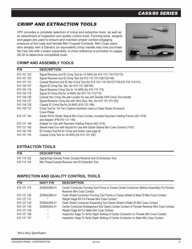
CRIMP AND EXTRACTION TOOLSVPC provides a complete selection of crimp and extraction tools, as well as an assortment of inspection and quality control tools. Forming tools, weights and gages are used to ensure and maintain proper contact engaging pressure of the male and female Mini Coaxial Contacts. Mini Coax users who already own a Daniel’s (or equivalent) crimp handle may now purchase the Hex Die with Locator separately. A cross reference is provided on pages 28-30 to determine compatible tools.
CRIMP AND ASSEMBLY TOOLSP/N DESCRIPTION 910 101 102 Signal Receiver and ID Crimp Tool for 14 AWG (for 610 110 174/172/173)910 101 103 Signal Receiver and ID Crimp Tool (for 610 110 101/108/125/146)910 101 115 Coaxial Receiver and ID Hex Crimp Tool (for 610 103 115/130/157/159,610 104 114/141)910 104 107 Signal ID Crimp Die, Std. (for 610 110 108/146)910 104 116 Signal Receiver Crimp Die for 14 AWG (for 610 110 174)910 104 118 Signal ID Crimp Die for 14 AWG (for 610 110 172/173)910 104 126 Coaxial Hex Crimp Die with Locator for use with Daniels HX4 Crimp Tool Handle910 104 127 Signal Receiver Crimp Die with Wire Stop, Std. (for 610 110 101/125)910 104 128 Coaxial ID Crimp Die for 24 AWG (610 103 166)910 105 110 Crimp Tool for 1/4 Turn Captive Hardware Used on Deep Drawn Enclosure Cover Plates 910 121 144 Solder Kit for Solder Sleeve Mini Coax Contact, Includes Raychem Holding Fixture (AD-1319) and Adapter (P/N 910 121 149)910 121 149 Adapter for Use with Raychem Holding Fixture (AD-1319)910 121 160 Steinel Heat Gun with Nozzle for Use with Solder Sleeve Mini Coax Contact (110V)910 102 105 ID Contact Tool Kit for Crimp and Solder (see page 8)910 101 118 Coaxial Crimp Tool for 24 AWG (for 610 103 166)
EXTRACTION TOOLSP/N DESCRIPTION 910 110 102 Signal/High Density Power Contact Receiver and ID Extraction Tool910 112 104 Mini Power/Coaxial Receiver and ID Extraction Tool
INSPECTION AND QUALITY CONTROL TOOLSP/N NAVY P/N DESCRIPTION 910 121 119 2038AS390-01 Center Conductor Forming Tool Forms or Closes Center Conductor (Before Assembly) On Female Receiver Mini Coax Contact910 121 126 2038AS389-01 Outer Shield Conductor Forming Tool Forms or Closes Shield of Male ID Mini Coax Contact 910 121 131 * Weight Gage Kit For Female Mini Coax Contact910 121 142 2038AS394-01 Outer Shield Conductor Expanding Tool Opens Shield of Male ID Mini Coax Contact 910 121 143 2038AS393-01 Center Conductor Enlargement Tool Opens Center Contact of Female Receiver Mini Coax Contact910 121 155 * Weight Gage Kit For Male Mini Coax Contact910 121 156 * Inspection Gage To Verify Depth Setting of Center Conductor on Female Mini Coax Contact910 121 157 * Inspection Gage To Verify Depth Setting of Center Conductor on Male Mini Coax Contact
*Not a Navy Specification
28 vpc.com VIRGINIA PANEL CORPORATION
CASS/80 SERIES
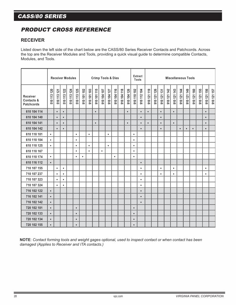
PRODUCT CROSS REFERENCE
RECEIVER
Listed down the left side of the chart below are the CASS/80 Series Receiver Contacts and Patchcords. Across the top are the Receiver Modules and Tools, providing a quick visual guide to determine compatible Contacts, Modules, and Tools.
NOTE: Contact forming tools and weight gages optional, used to inspect contact or when contact has been damaged (Applies to Receiver and ITA contacts.)
Receiver Modules Crimp Tools & Dies Extract Tools Miscellaneous Tools
Receiver Contacts & Patchcords 51
0 113
120
510 1
13 12
1
510 1
13 12
2
510 1
13 12
4
510 1
13 12
5
910 1
01 10
2
910 1
01 10
3
910 1
01 11
5
910 1
04 10
7
910 1
04 12
7
910 1
04 11
6
910 1
04 11
8
910 1
04 12
6
910 1
10 10
2
910 1
12 10
4
910 1
21 11
9
910 1
21 12
6
910 1
21 13
1
910 1
21 14
2
910 1
21 14
3
910 1
21 14
4
910 1
21 14
9
910 1
21 16
0
910 1
21 15
5
910 1
21 15
6
910 1
21 15
7
610 104 114 • • • • • • • • •610 104 140 • • • • •610 104 141 • • • • • • • • •610 104 142 • • • • • • • •610 110 101 • • • • • 610 110 104 • • • 610 110 125 • • • • • 610 110 167 610 110 174 610 116 112 • •710 107 155 • • • • • •710 107 237 • • • • • •710 107 323 • • •710 107 324 • • • 716 102 122 • • 716 102 141 • • 716 102 142 • • 720 102 101 • • •720 102 133 • • •720 102 134 • • •720 102 155 • • •
• • • • • • • • •
VIRGINIA PANEL CORPORATION vpc.com 29
CASS/80 SERIES
PRODUCT CROSS REFERENCE
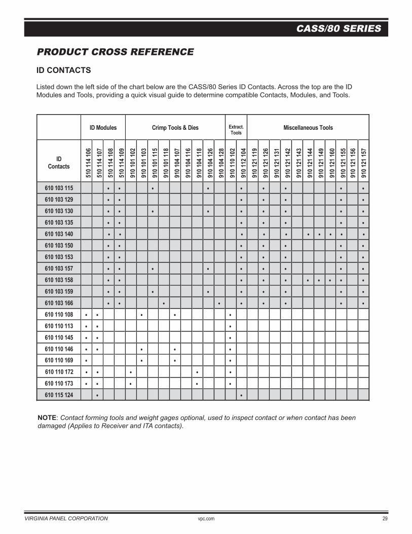
ID CONTACTS
Listed down the left side of the chart below are the CASS/80 Series ID Contacts. Across the top are the ID Modules and Tools, providing a quick visual guide to determine compatible Contacts, Modules, and Tools.
NOTE: Contact forming tools and weight gages optional, used to inspect contact or when contact has been damaged (Applies to Receiver and ITA contacts).
ID Modules Crimp Tools & Dies Extract. Tools
Miscellaneous Tools
ID Contacts
510 1
14 10
6 51
0 114
107
510 1
14 10
8 51
0 114
109
910 1
01 10
2 91
0 101
103
910 1
01 11
5 91
0 101
118
910 1
04 10
7 91
0 104
116
910 1
04 11
8 91
0 104
126
910 1
04 12
8 91
0 110
102
910 1
12 10
4 91
0 121
119
910 1
21 12
6 91
0 121
131
910 1
21 14
2 91
0 121
143
910 1
21 14
4 91
0 121
149
910 1
21 16
0 91
0 121
155
910 1
21 15
6 91
0 121
157
610 103 115 • • • • • • • • •610 103 129 • • • • • • •610 103 130 • • • • • • • • •610 103 135 • • • • • • •610 103 140 • • • • • • • • • • 610 103 150 • • • • • • • 610 103 153 • • • • • • • 610 103 157 • • • • • • • • • 610 103 158 • • • • • • • • • •610 103 159 • • • • • • • • •610 103 166 • • • • • • • • •610 110 108 • • • • •610 110 113 • • •
610 110 172 • • • • •
610 110 145 • • • 610 110 146 • • • • •
610 110 173 • • • • •
610 110 169 • • • •
610 115 124 • •
30 vpc.com VIRGINIA PANEL CORPORATION
CASS/80 SERIES
PRODUCT CROSS REFERENCE
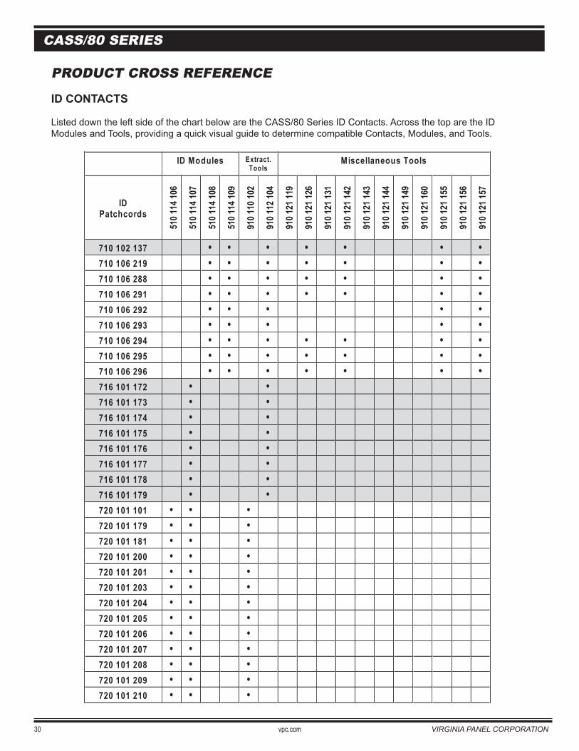
ID CONTACTS
Listed down the left side of the chart below are the CASS/80 Series ID Contacts. Across the top are the ID Modules and Tools, providing a quick visual guide to determine compatible Contacts, Modules, and Tools.
ID Modules Extract.Tools
Miscellaneous Tools
IDPatchcords
510 1
14 10
6
510 1
14 10
7
510 1
14 10
8
510 1
14 10
9
910 1
10 10
2
910 1
12 10
4
910 1
21 11
9
910 1
21 12
6
910 1
21 13
1
910 1
21 14
2
910 1
21 14
3
910 1
21 14
4
910 1
21 14
9
910 1
21 16
0
910 1
21 15
5
910 1
21 15
6
910 1
21 15
7
710 102 137 • • • • • • •710 106 219 • • • • • • •710 106 288 • • • • • • •710 106 291 • • • • • • •710 106 292 •••••710 106 293 •••••710 106 294 • • • • • • •710 106 295 • • • • • • •710 106 296 • • • • • • •716 101 172 • •716 101 173 • •716 101 174 • •716 101 175 • •716 101 176 • •716 101 177 • •716 101 178 • •716 101 179 • •720 101 101 • • •720 101 179 • • •720 101 181 • • •720 101 200 • • •720 101 201 • • •720 101 203 • • •720 101 204 • • •720 101 205 • • •720 101 206 • • •720 101 207 • • •720 101 208 • • •720 101 209 • • •720 101 210 • • •
VIRGINIA PANEL CORPORATION vpc.com 31
CASS/80 SERIES
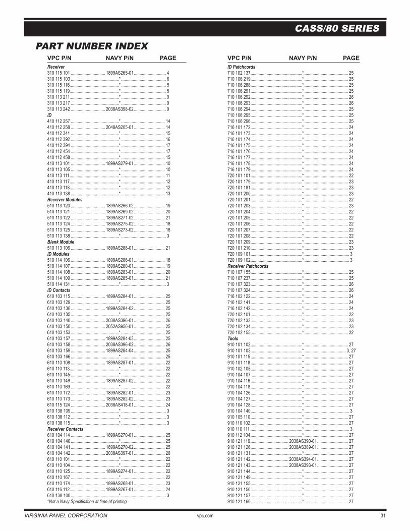
PART NUMBER INDEXVPC P/N NAVY P/N PAGE Receiver310 115 101 .............................. 1899AS265-01 ............................ 4310 115 103 ..........................................* ....................................... 6310 115 116 ...........................................* ....................................... 5310 115 119 ...........................................* ....................................... 5 310 113 211 ...........................................* ....................................... 9 310 113 217 ..........................................* ....................................... 9 310 113 242 .............................. 2038AS398-02 ............................ 9 ID410 112 257 ..........................................* ...................................... 14410 112 258 .............................. 2048AS205-01 ........................... 14410 112 341 ..........................................* ...................................... 15410 112 392 ..........................................* ...................................... 16410 112 394 ..........................................* ...................................... 17410 112 454 ..........................................* ...................................... 17410 112 458 ..........................................* ...................................... 15410 113 101 .............................. 1899AS279-01 ........................... 10410 113 105 ..........................................* ...................................... 10410 113 111 ...........................................* ...................................... 11410 113 117 ...........................................* ...................................... 12410 113 118 ...........................................* ...................................... 12410 113 138 ..........................................* ...................................... 13 Receiver Modules510 113 120 .............................. 1899AS266-02 ........................... 19510 113 121 .............................. 1899AS269-02 ........................... 20 510 113 122 .............................. 1899AS271-02 ........................... 21510 113 124 .............................. 1899AS275-02 ........................... 18510 113 125 .............................. 1899AS273-02 ........................... 18510 113 138 ..........................................* ....................................... 3 Blank Module510 113 106 .............................. 1899AS288-01 ........................... 21 ID Modules510 114 106 .............................. 1899AS286-01 ........................... 18510 114 107 .............................. 1899AS280-01 ........................... 19 510 114 108 .............................. 1899AS283-01 ........................... 20510 114 109 .............................. 1899AS285-01 ........................... 21510 114 131 ..........................................* ....................................... 3 ID Contacts610 103 115 .............................. 1899AS284-01 ........................... 25610 103 129 ..........................................* ...................................... 25610 103 130 .............................. 1899AS284-02 ........................... 25610 103 135 ..........................................* ...................................... 25610 103 140 .............................. 2038AS396-01 ........................... 26610 103 150 .............................. 2052AS956-01 ........................... 25610 103 153 ..........................................* ...................................... 25610 103 157 .............................. 1899AS284-03 ........................... 25610 103 158 .............................. 2038AS396-02 ........................... 26 610 103 159 .............................. 1899AS284-04 ........................... 25610 103 166 ..........................................* ...................................... 25610 110 108 .............................. 1899AS287-01 ........................... 22610 110 113 ...........................................* ...................................... 22610 110 145 ..........................................* ...................................... 22610 110 146 .............................. 1899AS287-02 ........................... 22610 110 169 ..........................................* ...................................... 22610 110 172 .............................. 1899AS282-01 ........................... 23610 110 173 .............................. 1899AS282-02 ........................... 23610 115 124 .............................. 2038AS418-01 ........................... 24 610 138 109 ..........................................* ....................................... 3610 138 112 ..........................................* ....................................... 3 610 138 115 ..........................................* ....................................... 3 Receiver Contacts610 104 114 .............................. 1899AS270-01 ........................... 25610 104 140 ..........................................* ...................................... 25610 104 141 .............................. 1899AS270-02 ........................... 25610 104 142 .............................. 2038AS397-01 ........................... 26610 110 101 ..........................................* ...................................... 22610 110 104 ..........................................* ...................................... 22610 110 125 .............................. 1899AS274-01 ........................... 22610 110 167 ..........................................* ...................................... 22610 110 174 .............................. 1899AS268-01 ........................... 23610 116 112 ............................... 1899AS267-01 ........................... 24 610 138 100 ..........................................* ....................................... 3 *Not a Navy Specification at time of printing
VPC P/N NAVY P/N PAGEID Patchcords710 102 137 .............................................* ...................................... 25710 106 219 .............................................* ...................................... 25 710 106 288 .............................................* ...................................... 25710 106 291 .............................................* ...................................... 25710 106 292 .............................................* ...................................... 26710 106 293 .............................................* ...................................... 26710 106 294 .............................................* ...................................... 25710 106 295 .............................................* ...................................... 25710 106 296 .............................................* ...................................... 25716 101 172 .............................................* ...................................... 24716 101 173 .............................................* ...................................... 24716 101 174 .............................................* ...................................... 24716 101 175 .............................................* ...................................... 24716 101 176 .............................................* ...................................... 24716 101 177 .............................................* ...................................... 24716 101 178 .............................................* ...................................... 24716 101 179 .............................................* ...................................... 24 720 101 101 .............................................* ...................................... 22720 101 179 .............................................* ...................................... 23720 101 181 .............................................* ...................................... 23 720 101 200 .............................................* ...................................... 23720 101 201 .............................................* ...................................... 22720 101 203 .............................................* ...................................... 23720 101 204 .............................................* ...................................... 22 720 101 205 .............................................* ...................................... 22720 101 206 .............................................* ...................................... 22720 101 207 .............................................* ...................................... 22720 101 208 .............................................* ...................................... 22720 101 209 .............................................* ...................................... 23720 101 210 .............................................* ...................................... 23 720 109 101 .............................................* ....................................... 3720 109 102 .............................................* ....................................... 3Receiver Patchcords710 107 155 .............................................* ...................................... 25710 107 237 .............................................* ...................................... 25710 107 323 .............................................* ...................................... 26710 107 324 .............................................* ...................................... 26716 102 122 .............................................* ...................................... 24716 102 141 .............................................* ...................................... 24 716 102 142 .............................................* ...................................... 24720 102 101 .............................................* ...................................... 22720 102 133 .............................................* ...................................... 23720 102 134 .............................................* ...................................... 23720 102 155 .............................................* ...................................... 22Tools910 101 102 .............................................* ...................................... 27910 101 103 .............................................* .................................... 3, 27910 101 115 .............................................* ...................................... 27910 101 118 .............................................* ...................................... 27910 102 105 .............................................* ...................................... 27910 104 107 ............................................* ...................................... 27910 104 116 .............................................* ...................................... 27910 104 118 .............................................* ...................................... 27910 104 126 .............................................* ...................................... 27910 104 127 .............................................* ...................................... 27910 104 128 .............................................* ...................................... 27910 104 140 .............................................* ....................................... 3910 105 110 .............................................* ...................................... 27910 110 102 .............................................* ...................................... 27910 110 111 .............................................* ....................................... 3910 112 104 .............................................* ...................................... 27910 121 119 ................................. 2038AS390-01 ........................... 27910 121 126 ................................. 2038AS389-01 ........................... 27910 121 131 .............................................* ...................................... 27910 121 142 ................................. 2038AS394-01 ........................... 27910 121 143 ................................. 2038AS393-01 ........................... 27910 121 144 .............................................* ...................................... 27910 121 149 .............................................* ...................................... 27910 121 155 .............................................* ...................................... 27910 121 156 .............................................* ...................................... 27910 121 157 .............................................* ...................................... 27 910 121 160 .............................................* ...................................... 27

32 vpc.com VIRGINIA PANEL CORPORATION
CASS/80 SERIES
NOTES:

VIRGINIA PANEL CORPORATION vpc.com 33
CASS/80 SERIES
NOTES:

34 vpc.com VIRGINIA PANEL CORPORATION
CASS/80 SERIES
NOTES:

Additional specifications for technical documents and user manuals can be found at www.vpc.com.
Disclaimer: Virginia Panel Corporation reserves the right to change or alter content without notice.
VPC is a registered trademark of Virginia Panel Corporation. Delrin is a registered trademark of Dupont Corporation. Solder Sleeve is a registered trademark of Raychem Corporation.

1400 New Hope RoadWaynesboro, VA 22980-2647TEL: (540) 932-3300FAX: (540) 932-3369www.vpc.com
Rev. 6/7/07