Embed Size (px)
Citation preview

Massive MIMO for Cellular-Connected UAV:Challenges and Promising Solutions
Yi Huang, Qingqing Wu, Rui Lu, Xiaoming Peng, and Rui Zhang
Abstract—Massive multiple-input multiple-output (MIMO) is apromising technology for enabling cellular-connected unmannedaerial vehicle (UAV) communications in the future. Equipped withfull-dimensional large arrays, ground base stations (GBSs) canapply adaptive fine-grained three-dimensional (3D) beamformingto mitigate the strong interference between high-altitude UAVsand low-altitude terrestrial users, thus significantly enhancingthe network spectral efficiency. However, the performance gainof massive MIMO critically depends on the accurate channelstate information (CSI) of both UAVs and terrestrial users atthe GBSs, which is practically difficult to achieve due to UAV-induced pilot contamination and UAV’s high mobility in 3D.Moreover, the increasingly popular applications relying on a largegroup of coordinated UAVs or UAV swarm as well as the prac-tical hybrid GBS beamforming architecture for massive MIMOfurther complicate the pilot contamination and channel/beamtracking problems. In this article, we provide an overview ofthe above challenging issues, propose new solutions to cope withthem, and discuss about promising directions for future research.Preliminary simulation results are also provided to validate theeffectiveness of proposed solutions.
I. INTRODUCTION
In the past decade, there has been an increasing demandfor unmanned aerial vehicles (UAVs) in a proliferation ofnew applications, such as aerial photography, cargo delivery,surveillance, airborne communication, etc. The basic commu-nication requirements for UAVs can be classified into twotypes: the control and non-payload communication (CNPC)for command and control message that requires high reliabilityand low latency, and the payload communication for applica-tion data such as high-rate video streaming. As compared tothe existing UAV-ground communications over the unlicensedspectrum (e.g., 2.4 GHz) that are unreliable, insecure, and oflimited range and data rate, the almost ubiquitous connectivityand ultra-low-latency backhaul of the fifth-generation (5G)cellular network are promising to enable far more reliable andsignificantly higher capacity communication links for UAVsin a cost-effective manner [1].
Despite its great potential, cellular-connected UAV bringsnew challenges in operating 5G networks in the future, high-lighted as follows.
• Severe Air-Ground Interference: The wireless channelsbetween high-altitude UAVs and ground base stations(GBSs) are typically dominated by the strong line-of-sight (LoS) path [1]. As shown in Fig. 1(a), althoughLoS links bring high degrees of macro-diversity for UAVsto potentially connect with more available GBSs, theyinevitably cause severe interference to the concurrenttransmissions of the ground user equipments (GUEs)
Insufficient 3D
coverage
Drone camera
Drone relayDrone delivery
Drone surveillance
UAV-to-GBS
interference GBS-to-UAV
interference
Drone camera
Drone surveillance Drone delivery
Drone relay
(a) Fixed-pattern array tilted downward at the (current) 4G GBS.
(b) Flexible 3D beamforming at the (future) 5G GBS.
Fig. 1. 4G/5G cellular networks serving both UAVs and GUEs.
over the same frequency channels in the uplink, andalso render the UAVs more vulnerable to the interferencefrom the co-channel GBSs transmitting to GUEs in thedownlink.
• Ubiquitous Three-Dimensional (3D) Coverage forUAVs: As shown in Fig. 1(a), although UAVs usuallyoperate in much higher altitude than GUEs, thus requiringthe GBSs to offer 3D signal coverage for them. However,the GBS antennas in the existing 4G network are typicallytilted downward to provide ground coverage only whilereducing the inter-cell interference among GUEs. Thisthus results in insufficient coverage for communicationswith UAVs in the sky.
Massive multiple-input multiple-output (MIMO) is a keytechnology that dramatically improves the spectral efficiencyof 5G wireless systems, by leveraging a large number ofGBS antennas to serve a small number of users. Due to itsenormous beamforming and full spatial multiplexing gains,massive MIMO has been applied recently to support UAVsfor resolving the aforementioned aerial-ground interferenceand 3D coverage issues [2]–[4]. As compared to traditionaltwo-dimensional (2D) beamforming towards the ground only,massive MIMO with 3D beamforming provides finer-grainedangle resolutions in both azimuth and elevation dimensions.
arX
iv:2
010.
0623
8v1
[cs
.IT
] 1
3 O
ct 2
020

2
Thus, it offers far more effective interference mitigation capa-bility in both the UAV uplink and downlink communicationsby exploiting the elevation angle difference between UAVs andGUEs [1], as shown in Fig. 1(b). Besides, 3D beamformingimproves connectivity and coverage for UAVs in the sky dueto more flexible elevation-domain beamforming.
Although massive MIMO is promising for interferencesuppression and coverage extension in cellular-connected UAVcommunications, it faces several practical challenges in serv-ing UAVs, e.g., pilot contamination incurred by UAVs withstrong LoS channels and channel/beam tracking for UAVswith 3D high mobility. Moreover, serving the UAV swarmand applying practical hybrid GBS beamforming architecturefor massive MIMO further complicate pilot contaminationand channel/beam tracking problems. This thus motivates thisarticle to provide an overview on the new issues and challengesin massive MIMO for supporting UAV communications. Newand promising solutions are also proposed to cope with them.Moreover, numerical examples are presented to demonstratethe effectiveness of the proposed solutions.
II. CHALLENGES FOR SERVING UAVS WITH MASSIVEMIMO
The performance of massive MIMO depends critically onthe accuracy of CSI for all served users (UAVs and GUEs) ateach GBS, which faces several new issues outlined as follows.
A. UAV-Induced Pilot ContaminationPilot contamination arising from multi-cell pilot reuse may
cause severe interference regardless of the number of GBSantennas [5]. To address this issue, using a large pilot reusefactor is an effective solution for terrestrial cellular networks,since it ensures that the GUEs sharing the same pilot aresufficiently far apart, thus rendering their pilot contaminationnegligible. However, the pilot contamination problem becomesmore challenging to solve in cellular-connected UAV com-munications. Specifically, UAV is usually at a much higheraltitude than GBSs and thus has strong LoS channels withthem in a much wider area as compared to GUE [6]. Thus,UAV causes severe pilot contamination with more users (GUEsas well as other UAVs) that reuse the same pilot, even whentheir serving GBSs are far from this UAV. Therefore, howto deal with the UAV-induced pilot contamination is a newchallenge in massive MIMO.
B. 3D Beam Tracking for UAVIn order to fully exploit the beamforming gain by massive
MIMO and provide 3D coverage for a flying UAV, its servingGBS needs to obtain accurate CSI for it over time via efficientbeam tracking. Different from the terrestrial fading channelsof GUEs with GBSs, UAVs have LoS links with their servingGBSs at most time via dynamic GBS association. Therefore,the serving GBSs for UAVs need to be able to simultaneouslytrack the azimuth and elevation angles of their LoS links withthe UAVs. Moreover, the high and 3D mobility of UAVs causesrapid channel phase variations over time and thus incurs more
frequent pilot transmissions for channel/beam tracking. Notethat the UAV-mounted Global Positioning System (GPS) iscostly to implement in practice to facilitate beam tracking.Even if the GPS is available, its precision (in the order ofmeters) is insufficient for accurate beam tracking and canonly provide coarse location information for helping reducethe training overhead. As a result, how to achieve efficient andprecise 3D beam tracking for UAVs by exploiting their uniquechannel characteristics with GBSs is a new and practicallyimportant problem.
C. Challenges in Serving UAV SwarmThe UAV swarm formed by a large group of coordinated
UAVs can accomplish more sophisticated tasks than a singleUAV and thus has attracted growing interest recently. However,obtaining accurate CSI for UAV swarm is also more chal-lenging for the serving GBS. On one hand, a large numberof UAVs in the UAV swarm generally require more pilotsassigned to them, thus causing more severe pilot contaminationand resulted interference with GUEs and other UAVs. On theother hand, tracking the channels of such a large number ofUAVs also incurs more pilot overhead, which would decreasethe communication throughput. To tackle the above problems,more efficient channel estimation and communication designsfor UAV swarm are imperative.
D. Considerations for Practical Hybrid BeamformingThe so-called hybrid digital and analog beamforming based
on the sub-array architecture has been widely adopted forimplementing massive MIMO in 5G [7]. To find the bestanalog beamforming directions towards users, 5G GBSs usu-ally perform exhaustive beam searching with multiple pilotsymbols sent by the users. However, if these beam searchingpilots are contaminated by the interfering UAVs, the GBS willfail to find the right analog beamforming direction towardsits served user, and thus beam misalignment occurs and lowsignal-to-noise ratio (SNR) is resulted. Thus, how to tackle thenew challenges due to UAVs as well as the practical hybridbeamforming at GBSs is also crucial.
III. PILOT DECONTAMINATION INCELLULAR-CONNECTED UAV COMMUNICATION
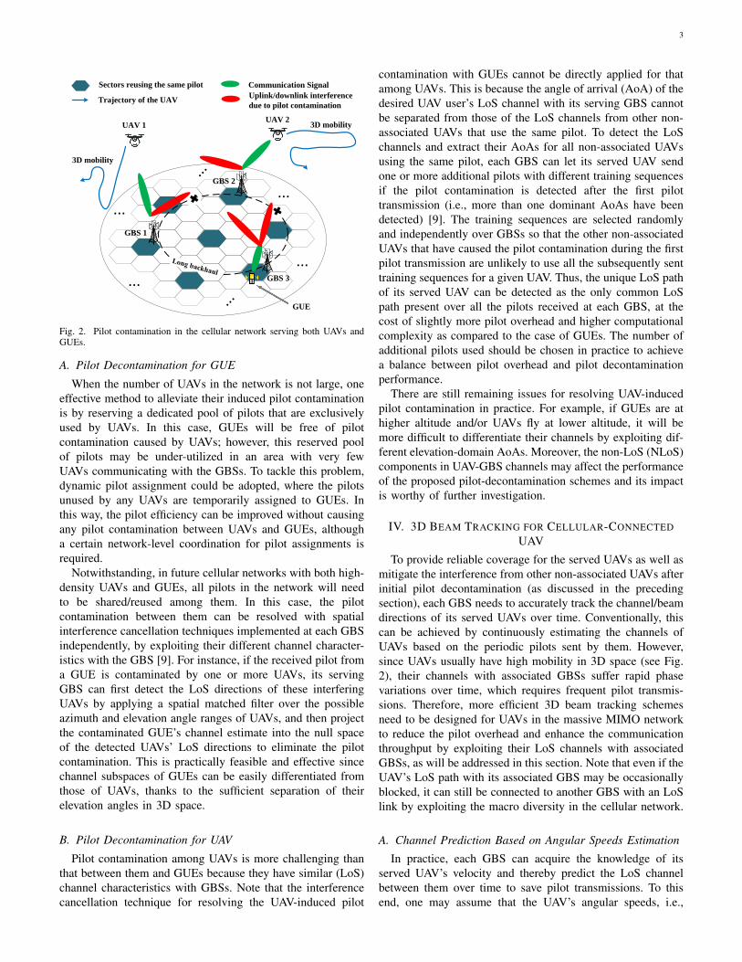
Fig. 2 shows the UAV-induced pilot contamination andresulted interference in a massive MIMO network due to thetypically strong LoS channels between UAVs and GBSs ina large area. It is worth noting that traditional pilot decon-tamination techniques for GUEs, such as large-scale fadingbased precoding scheme [5] or coordinated pilot assignmentscheme [8], are insufficient or even infeasible for cellular-connected UAV communications, since in this case they willrequire cooperation between far apart GBSs and hence incurmuch more signaling overhead and longer backhaul delay(see Fig. 2). Therefore, new and more efficient methods needto be devised to eliminate the effect of UAV-induced pilotcontamination, as detailed in the following.
3
...
...
...
...
UAV 2
GUE
UAV 1
3D mobility
3D mobility
GBS 1
GBS 2
GBS 3
Sectors reusing the same pilot
Trajectory of the UAVUplink/downlink interference
due to pilot contamination
Communication Signal
Fig. 2. Pilot contamination in the cellular network serving both UAVs andGUEs.
A. Pilot Decontamination for GUE
When the number of UAVs in the network is not large, oneeffective method to alleviate their induced pilot contaminationis by reserving a dedicated pool of pilots that are exclusivelyused by UAVs. In this case, GUEs will be free of pilotcontamination caused by UAVs; however, this reserved poolof pilots may be under-utilized in an area with very fewUAVs communicating with the GBSs. To tackle this problem,dynamic pilot assignment could be adopted, where the pilotsunused by any UAVs are temporarily assigned to GUEs. Inthis way, the pilot efficiency can be improved without causingany pilot contamination between UAVs and GUEs, althougha certain network-level coordination for pilot assignments isrequired.
Notwithstanding, in future cellular networks with both high-density UAVs and GUEs, all pilots in the network will needto be shared/reused among them. In this case, the pilotcontamination between them can be resolved with spatialinterference cancellation techniques implemented at each GBSindependently, by exploiting their different channel character-istics with the GBS [9]. For instance, if the received pilot froma GUE is contaminated by one or more UAVs, its servingGBS can first detect the LoS directions of these interferingUAVs by applying a spatial matched filter over the possibleazimuth and elevation angle ranges of UAVs, and then projectthe contaminated GUE’s channel estimate into the null spaceof the detected UAVs’ LoS directions to eliminate the pilotcontamination. This is practically feasible and effective sincechannel subspaces of GUEs can be easily differentiated fromthose of UAVs, thanks to the sufficient separation of theirelevation angles in 3D space.
B. Pilot Decontamination for UAV
Pilot contamination among UAVs is more challenging thanthat between them and GUEs because they have similar (LoS)channel characteristics with GBSs. Note that the interferencecancellation technique for resolving the UAV-induced pilot
contamination with GUEs cannot be directly applied for thatamong UAVs. This is because the angle of arrival (AoA) of thedesired UAV user’s LoS channel with its serving GBS cannotbe separated from those of the LoS channels from other non-associated UAVs that use the same pilot. To detect the LoSchannels and extract their AoAs for all non-associated UAVsusing the same pilot, each GBS can let its served UAV sendone or more additional pilots with different training sequencesif the pilot contamination is detected after the first pilottransmission (i.e., more than one dominant AoAs have beendetected) [9]. The training sequences are selected randomlyand independently over GBSs so that the other non-associatedUAVs that have caused the pilot contamination during the firstpilot transmission are unlikely to use all the subsequently senttraining sequences for a given UAV. Thus, the unique LoS pathof its served UAV can be detected as the only common LoSpath present over all the pilots received at each GBS, at thecost of slightly more pilot overhead and higher computationalcomplexity as compared to the case of GUEs. The number ofadditional pilots used should be chosen in practice to achievea balance between pilot overhead and pilot decontaminationperformance.
There are still remaining issues for resolving UAV-inducedpilot contamination in practice. For example, if GUEs are athigher altitude and/or UAVs fly at lower altitude, it will bemore difficult to differentiate their channels by exploiting dif-ferent elevation-domain AoAs. Moreover, the non-LoS (NLoS)components in UAV-GBS channels may affect the performanceof the proposed pilot-decontamination schemes and its impactis worthy of further investigation.
IV. 3D BEAM TRACKING FOR CELLULAR-CONNECTEDUAV
To provide reliable coverage for the served UAVs as well asmitigate the interference from other non-associated UAVs afterinitial pilot decontamination (as discussed in the precedingsection), each GBS needs to accurately track the channel/beamdirections of its served UAVs over time. Conventionally, thiscan be achieved by continuously estimating the channels ofUAVs based on the periodic pilots sent by them. However,since UAVs usually have high mobility in 3D space (see Fig.2), their channels with associated GBSs suffer rapid phasevariations over time, which requires frequent pilot transmis-sions. Therefore, more efficient 3D beam tracking schemesneed to be designed for UAVs in the massive MIMO networkto reduce the pilot overhead and enhance the communicationthroughput by exploiting their LoS channels with associatedGBSs, as will be addressed in this section. Note that even if theUAV’s LoS path with its associated GBS may be occasionallyblocked, it can still be connected to another GBS with an LoSlink by exploiting the macro diversity in the cellular network.
A. Channel Prediction Based on Angular Speeds Estimation
In practice, each GBS can acquire the knowledge of itsserved UAV’s velocity and thereby predict the LoS channelbetween them over time to save pilot transmissions. To thisend, one may assume that the UAV’s angular speeds, i.e.,

4
the instantaneous variation rates of its azimuth and elevationangles, stay approximately unchanged during a given shortperiod [10]. As such, each GBS can first detect the azimuthand elevation angles of its served UAV’s LoS path over twonon-consecutive beam tracking pilots received from the UAV,and then estimate the UAV’s angular speeds as the variationsof its azimuth and elevation angles normalized to the timedifference between the two pilot symbols, respectively. Basedon the estimated angular speeds, the UAV’s azimuth/elevationangles as well as its LoS channel in subsequent time slotscan be predicted without the need of sending new pilots. Theabove algorithm can be implemented with low complexityyet without the help of conventional positioning technologiessuch as GPS. However, the LoS channel prediction becomesinaccurate once the UAV’s angular speeds change. As a result,the beamforming gain at the GBS degrades over time. Toovercome this issue, the GBS can estimate the angular speedsof the UAV from time to time based on its periodically sentpilots.B. Kalman Filter Based Channel Tracking
Kalman filter based channel tracking [11] is another ef-fective method, where the GBS iteratively performs channelprediction for its served UAV and updates the predictedchannel based on independent channel measurement (e.g.,that obtained from conventional channel estimation pilots).Note that although the algorithm presented in the previoussubsection can be applied to the above channel prediction step,more sophisticated channel prediction algorithms can also beconsidered to improve the performance. For example, eachGBS can estimate the UAV’s velocity and acceleration jointlyfor channel prediction by modeling its mobility as a second-order dynamic system.
In general, the Kalman filter based method is able to obtainmore accurate prediction of the UAV’s channel as comparedto the previously introduced method based on angular speedsestimation, since the channel prediction error in former casecan be further reduced by exploiting the additional channelmeasurement in the update step. However, this requires morepilot overhead as well as higher processing complexity atthe GBS. Besides, if UAV’s velocity changes too rapidly, thechannel prediction error will grow substantially even with theKalman filter based channel tracking.
To further improve the accuracy and robustness of channeltracking for UAVs, multi-GBS cooperation is one promisingdirection for future research. Specifically, the LoS-dominantchannels of a UAV with multiple GBSs bring a higher macro-diversity gain as compared to that of a GUE. Thus, the pilotssent by a UAV are likely to be received by neighbouring GBSsof its serving GBS over LoS channels, each of which can helpestimate the UAV’s velocity. As such, the UAV’s serving GBScan collect information on its velocity from these neighbouringGBSs to improve the channel prediction performance.
V. MASSIVE MIMO COMMUNICATION WITH UAV SWARM
Although it is practically appealing to employ massiveMIMO to support communications between GBS and UAVswarm [3], the large number of UAVs in a swarm may require
...
Phase II: Swarm head broadcasts
the message to the other UAVs
UAV swarm Uplink pilots Interference caused by pilot contamination
...
...
Phase I: GBS transmits (common)
message to swarm head
Swarm headSwarm head
Insufficient angle difference
...
Excessive pilot
overhead
D2D communications among UAVs
(a) Challenges in channel estimation with UAV swarm
(b) D2D-assisted communication protocol for UAV swarm
Fig. 3. D2D based solution for supporting UAV swarm with massive MIMO.
excessive pilots for channel estimation and thus cause moresevere pilot contamination in the network, as shown in Fig.3(a). Moreover, the angle difference among UAVs in the sameswarm is practically small. Thus, their LoS channels with thesame serving GBS are more difficult to be differentiated ascompared to the single-UAV case, which renders the proposedpilot decontamination methods in Section III less effective.Therefore, new and more effective channel estimation andcommunication designs are needed for supporting UAV swarmwith massive MIMO.
One potential solution is to choose a UAV head in theswarm for channel estimation with the serving GBS onlyby sending a pilot in the uplink. In this way, the pilotoverhead is substantially reduced, while the UAV-induced pilotcontamination becomes the same as that in the single-UAVcase and thus can be resolved by the methods proposed inSection III. After channel estimation, a two-phase transmissionprotocol can be adopted for enabling communications betweenthe GBS and its associated UAV swarm, as shown in Fig. 3(b)for the case of downlink communication. In phase I, the GBSbeams toward the swarm head based on the (uplink) estimatedCSI for sending a (common) message to it. In phase II, device-to-device (D2D) communications among the UAVs are utilizedsuch that the swarm head broadcasts its received message tothe other UAVs for them to retrieve their intended informationfrom the common message. Similarly, D2D-assisted uplinkcommunication from UAV swarm to GBS can be implemented.
There are interesting aspects of the above D2D-assistedmassive MIMO communication with UAV swarm worthy offurther investigation. Firstly, the durations of the two phasessubject to a given transmission delay need to be properly setto strike an optimal balance between the achievable rates in

5
the two phases so as to maximize the system throughput. Sec-ondly, when the number of UAVs in the swarm is excessivelylarge, multiple swarm heads may be appointed for reducingthe D2D transmission delay in phase II. However, this mayincur over-the-air interference among the swarm heads as wellas more severe pilot contamination in phase I. Thus, optimaldesign of swarm heads and their D2D transmission protocolis also crucial to maximize the effective system throughput.For example, a UAV head can be selected based on higherprobability of LoS path with the GBS for improving thelink quality. Furthermore, it should consume minimum powerto communicate with the rest of swarm members over thewireless links between them [12].
VI. PRACTICAL CONSIDERATIONS FOR HYBRIDBEAMFORMING
Low-cost hybrid analog and digital beamforming with muchless RF chains required than full-digital beamforming is com-monly adopted in massive MIMO systems. There are twopractical architectures for implementing it at the GBS, namely,full-complexity or reduced-complexity [7], as shown in Figs.4(a) and 4(b) respectively. In the full-complexity case, eachRF chain is connected to all antenna elements and thus theGBS can combine multiple analog beams in the digital domain(where each analog beam corresponds to an RF chain). Whilein the reduced-complexity case, each RF chain is exclusivelyconnected to a sub-array and all sub-arrays perform analogbeamforming independently.
For both full-complexity and reduced-complexity architec-tures, the beam searching pilots received by the GBS maybe contaminated by non-associated UAVs with strong LoSchannels. Moreover, the interference cancellation based pilotdecontamination proposed in Section III becomes ineffectivesince the number of RF chains at the GBS is insufficient todetect the LoS directions of the interfering UAVs directly.Thus, new solutions are needed to resolve pilot contaminationbetween UAVs and GUEs as well as among UAVs in beamsearching. One possible solution is that the GBS can restrictthe angle-searching range for its associated GUE towardsthe ground only, such that the pilot contamination betweenthe GUE and non-associated UAVs can be effectively alle-viated. Meanwhile, when the pilot of the associated UAV iscontaminated by non-associated UAVs, the GBS can let itsassociated UAV send additional pilots randomly selected forbeam searching, and thereby the desired beam direction of itsassociated UAV can be found as the common one detectedfrom all the pilots received (similarly as in Section III fordifferentiating the LoS path of the associated UAV from thoseof non-associated UAVs). Alternatively, the GBS can senddownlink beam searching pilots in the directions found in theuplink training, and its associated UAV then sends the indexof the desired beam direction back to the GBS, which onlyrequires few additional pilots in practice.
On the other hand, due to 3D mobility of UAVs, beamsearching in both azimuth and elevation dimensions are gener-ally required, which incurs more pilot overhead as comparedto GUEs. For reducing pilot overhead in beam searching, one
Phase shifter
Digital
precoder
RF chain
RF chain
...
Digital
precoder
RF chain
...
......
...
...
RF chain
...
Analog
beamforming
Analog
beamforming
...
(a) Full-complexity architecture (b) Reduced-complexity architecture
Fig. 4. Illustration of practical hybrid beamforming architecture.
practical approach is to use the hierarchical multi-resolutioncodebook [13], [14]. Starting with searching over the low-resolution beam directions in the codebook, the GBS firstobtains the coarse beam direction in azimuth/elevation di-mension for its served UAV, then refines it using the high-resolution beam directions in the codebook. However, theUAV with 3D and high mobility may cause fast channelvariation and hence the optimal beam varies quickly, whichstill requires frequent beam searching. To tackle this problem,analog beam prediction based on Kalman filter for millimeter-wave communications [15] can be applied for tracking theUAVs.
There are still remaining issues in communicating withUAVs via hybrid beamforming in massive MIMO, which isworth further investigating in the future. For example, howto solve the beam searching pilot contamination issue andimprove beam searching efficiency for UAV swarms is stillan open problem. Besides, joint optimization for channelestimation and data transmission for UAV swarms with hybridbeamforming is crucial but unaddressed yet.
VII. SIMULATION RESULTS AND DISCUSSIONS
In this section, simulation results are presented to verifythe effectiveness of the pilot decontamination and 3D beamtracking techniques proposed in Sections III and IV, respec-tively. Consider a cellular system consisting of 7 macro siteswith 3 sectors per site. Moreover, it is assumed that eachsector is equipped with an 8× 16 uniform planar array (UPA)with 8 and 16 antennas in vertical and horizontal dimensions,respectively. Full-digital beamforming is assumed for evalu-ating the performance of proposed pilot decontamination and3D beam tracking methods. The carrier frequency is 3.5GHzand the channel bandwidth is 1MHz. The altitude of eachGUE is fixed to 1.5meter (m), whereas that of each UAV isuniformly distributed between 50m and 300m. The GBS’stransmit power is 46 dBm while the user’s transmit poweris 23 dBm. The noise power density is −174 dBm/Hz withadditional noise figure of 9 dB in the downlink and 5 dB in theuplink. The 3GPP urban macro (UMa) scenario is consideredwith the same channel modeling as adopted in [16].
A. Pilot Decontamination
Consider a given frequency channel reused by 21 users (15UAVs and 6 GUEs) uniformly distributed over the sectorsfor evaluating the proposed pilot decontamination schemes.The users are associated to the GBSs based on maximum
6
-20 -10 0 10 20 30 40 50
SINR (dB)
0
0.2
0.4
0.6
0.8
1C
.D.F
Ideal CSI, UAV
Pilot contamination, UAV
Proposed algorithm, UAV
Ideal CSI, GUE
Pilot contamination, GUE
Proposed algorithm, GUE
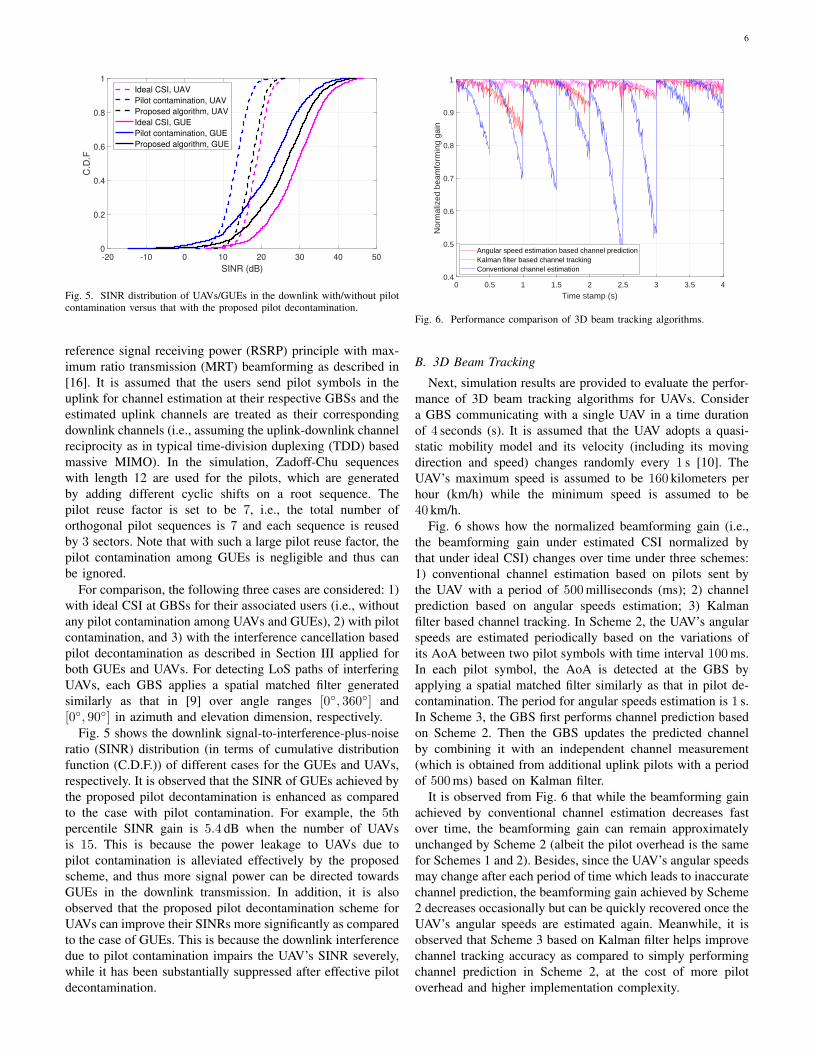
Fig. 5. SINR distribution of UAVs/GUEs in the downlink with/without pilotcontamination versus that with the proposed pilot decontamination.
reference signal receiving power (RSRP) principle with max-imum ratio transmission (MRT) beamforming as described in[16]. It is assumed that the users send pilot symbols in theuplink for channel estimation at their respective GBSs and theestimated uplink channels are treated as their correspondingdownlink channels (i.e., assuming the uplink-downlink channelreciprocity as in typical time-division duplexing (TDD) basedmassive MIMO). In the simulation, Zadoff-Chu sequenceswith length 12 are used for the pilots, which are generatedby adding different cyclic shifts on a root sequence. Thepilot reuse factor is set to be 7, i.e., the total number oforthogonal pilot sequences is 7 and each sequence is reusedby 3 sectors. Note that with such a large pilot reuse factor, thepilot contamination among GUEs is negligible and thus canbe ignored.
For comparison, the following three cases are considered: 1)with ideal CSI at GBSs for their associated users (i.e., withoutany pilot contamination among UAVs and GUEs), 2) with pilotcontamination, and 3) with the interference cancellation basedpilot decontamination as described in Section III applied forboth GUEs and UAVs. For detecting LoS paths of interferingUAVs, each GBS applies a spatial matched filter generatedsimilarly as that in [9] over angle ranges [0◦, 360◦] and[0◦, 90◦] in azimuth and elevation dimension, respectively.
Fig. 5 shows the downlink signal-to-interference-plus-noiseratio (SINR) distribution (in terms of cumulative distributionfunction (C.D.F.)) of different cases for the GUEs and UAVs,respectively. It is observed that the SINR of GUEs achieved bythe proposed pilot decontamination is enhanced as comparedto the case with pilot contamination. For example, the 5thpercentile SINR gain is 5.4 dB when the number of UAVsis 15. This is because the power leakage to UAVs due topilot contamination is alleviated effectively by the proposedscheme, and thus more signal power can be directed towardsGUEs in the downlink transmission. In addition, it is alsoobserved that the proposed pilot decontamination scheme forUAVs can improve their SINRs more significantly as comparedto the case of GUEs. This is because the downlink interferencedue to pilot contamination impairs the UAV’s SINR severely,while it has been substantially suppressed after effective pilotdecontamination.
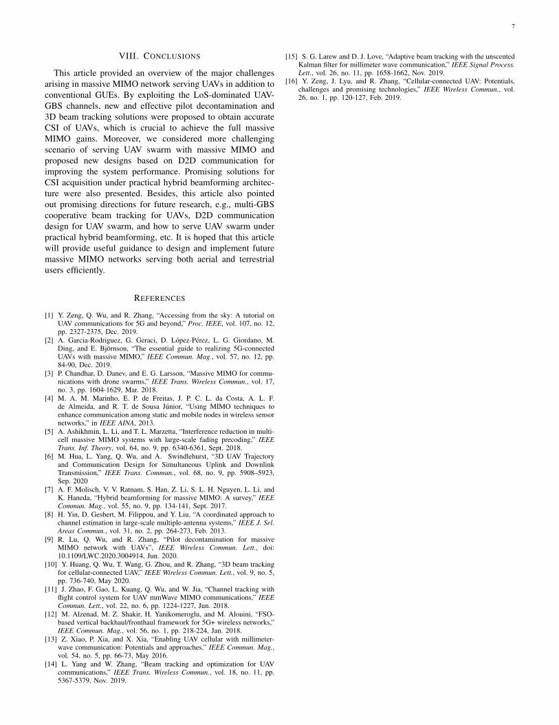
0 0.5 1 1.5 2 2.5 3 3.5 4
Time stamp (s)
0.4
0.5
0.6
0.7
0.8
0.9
1
Nor
mal
ized
bea
mfo
rmin
g ga
in
Angular speed estimation based channel predictionKalman filter based channel trackingConventional channel estimation
Fig. 6. Performance comparison of 3D beam tracking algorithms.
B. 3D Beam Tracking
Next, simulation results are provided to evaluate the perfor-mance of 3D beam tracking algorithms for UAVs. Considera GBS communicating with a single UAV in a time durationof 4 seconds (s). It is assumed that the UAV adopts a quasi-static mobility model and its velocity (including its movingdirection and speed) changes randomly every 1 s [10]. TheUAV’s maximum speed is assumed to be 160 kilometers perhour (km/h) while the minimum speed is assumed to be40 km/h.
Fig. 6 shows how the normalized beamforming gain (i.e.,the beamforming gain under estimated CSI normalized bythat under ideal CSI) changes over time under three schemes:1) conventional channel estimation based on pilots sent bythe UAV with a period of 500milliseconds (ms); 2) channelprediction based on angular speeds estimation; 3) Kalmanfilter based channel tracking. In Scheme 2, the UAV’s angularspeeds are estimated periodically based on the variations ofits AoA between two pilot symbols with time interval 100ms.In each pilot symbol, the AoA is detected at the GBS byapplying a spatial matched filter similarly as that in pilot de-contamination. The period for angular speeds estimation is 1 s.In Scheme 3, the GBS first performs channel prediction basedon Scheme 2. Then the GBS updates the predicted channelby combining it with an independent channel measurement(which is obtained from additional uplink pilots with a periodof 500ms) based on Kalman filter.
It is observed from Fig. 6 that while the beamforming gainachieved by conventional channel estimation decreases fastover time, the beamforming gain can remain approximatelyunchanged by Scheme 2 (albeit the pilot overhead is the samefor Schemes 1 and 2). Besides, since the UAV’s angular speedsmay change after each period of time which leads to inaccuratechannel prediction, the beamforming gain achieved by Scheme2 decreases occasionally but can be quickly recovered once theUAV’s angular speeds are estimated again. Meanwhile, it isobserved that Scheme 3 based on Kalman filter helps improvechannel tracking accuracy as compared to simply performingchannel prediction in Scheme 2, at the cost of more pilotoverhead and higher implementation complexity.
7
VIII. CONCLUSIONS
This article provided an overview of the major challengesarising in massive MIMO network serving UAVs in addition toconventional GUEs. By exploiting the LoS-dominated UAV-GBS channels, new and effective pilot decontamination and3D beam tracking solutions were proposed to obtain accurateCSI of UAVs, which is crucial to achieve the full massiveMIMO gains. Moreover, we considered more challengingscenario of serving UAV swarm with massive MIMO andproposed new designs based on D2D communication forimproving the system performance. Promising solutions forCSI acquisition under practical hybrid beamforming architec-ture were also presented. Besides, this article also pointedout promising directions for future research, e.g., multi-GBScooperative beam tracking for UAVs, D2D communicationdesign for UAV swarm, and how to serve UAV swarm underpractical hybrid beamforming, etc. It is hoped that this articlewill provide useful guidance to design and implement futuremassive MIMO networks serving both aerial and terrestrialusers efficiently.
REFERENCES
[1] Y. Zeng, Q. Wu, and R. Zhang, “Accessing from the sky: A tutorial onUAV communications for 5G and beyond,” Proc. IEEE, vol. 107, no. 12,pp. 2327-2375, Dec. 2019.
[2] A. Garcia-Rodriguez, G. Geraci, D. Lopez-Perez, L. G. Giordano, M.Ding, and E. Bjornson, “The essential guide to realizing 5G-connectedUAVs with massive MIMO,” IEEE Commun. Mag., vol. 57, no. 12, pp.84-90, Dec. 2019.
[3] P. Chandhar, D. Danev, and E. G. Larsson, “Massive MIMO for commu-nications with drone swarms,” IEEE Trans. Wireless Commun., vol. 17,no. 3, pp. 1604-1629, Mar. 2018.
[4] M. A. M. Marinho, E. P. de Freitas, J. P. C. L. da Costa, A. L. F.de Almeida, and R. T. de Sousa Junior, “Using MIMO techniques toenhance communication among static and mobile nodes in wireless sensornetworks,” in IEEE AINA, 2013.
[5] A. Ashikhmin, L. Li, and T. L. Marzetta, “Interference reduction in multi-cell massive MIMO systems with large-scale fading precoding,” IEEETrans. Inf. Theory, vol. 64, no. 9, pp. 6340-6361, Sept. 2018.
[6] M. Hua, L. Yang, Q. Wu, and A. Swindlehurst, “3D UAV Trajectoryand Communication Design for Simultaneous Uplink and DownlinkTransmission,” IEEE Trans. Commun., vol. 68, no. 9, pp. 5908–5923,Sep. 2020
[7] A. F. Molisch, V. V. Ratnam, S. Han, Z. Li, S. L. H. Nguyen, L. Li, andK. Haneda, “Hybrid beamforming for massive MIMO: A survey,” IEEECommun. Mag., vol. 55, no. 9, pp. 134-141, Sept. 2017.
[8] H. Yin, D. Gesbert, M. Filippou, and Y. Liu, “A coordinated approach tochannel estimation in large-scale multiple-antenna systems,” IEEE J. Sel.Areas Commun., vol. 31, no. 2, pp. 264-273, Feb. 2013.
[9] R. Lu, Q. Wu, and R. Zhang, “Pilot decontamination for massiveMIMO network with UAVs”, IEEE Wireless Commun. Lett., doi:10.1109/LWC.2020.3004914, Jun. 2020.
[10] Y. Huang, Q. Wu, T. Wang, G. Zhou, and R. Zhang, “3D beam trackingfor cellular-connected UAV,” IEEE Wireless Commun. Lett., vol. 9, no. 5,pp. 736-740, May 2020.
[11] J. Zhao, F. Gao, L. Kuang, Q. Wu, and W. Jia, “Channel tracking withflight control system for UAV mmWave MIMO communications,” IEEECommun. Lett., vol. 22, no. 6, pp. 1224-1227, Jun. 2018.
[12] M. Alzenad, M. Z. Shakir, H. Yanikomeroglu, and M. Alouini, “FSO-based vertical backhaul/fronthaul framework for 5G+ wireless networks,”IEEE Commun. Mag., vol. 56, no. 1, pp. 218-224, Jan. 2018.
[13] Z. Xiao, P. Xia, and X. Xia, “Enabling UAV cellular with millimeter-wave communication: Potentials and approaches,” IEEE Commun. Mag.,vol. 54, no. 5, pp. 66-73, May 2016.
[14] L. Yang and W. Zhang, “Beam tracking and optimization for UAVcommunications,” IEEE Trans. Wireless Commun., vol. 18, no. 11, pp.5367-5379, Nov. 2019.
[15] S. G. Larew and D. J. Love, “Adaptive beam tracking with the unscentedKalman filter for millimeter wave communication,” IEEE Signal Process.Lett., vol. 26, no. 11, pp. 1658-1662, Nov. 2019.
[16] Y. Zeng, J. Lyu, and R. Zhang, “Cellular-connected UAV: Potentials,challenges and promising technologies,” IEEE Wireless Commun., vol.26, no. 1, pp. 120-127, Feb. 2019.