Embed Size (px)
Citation preview
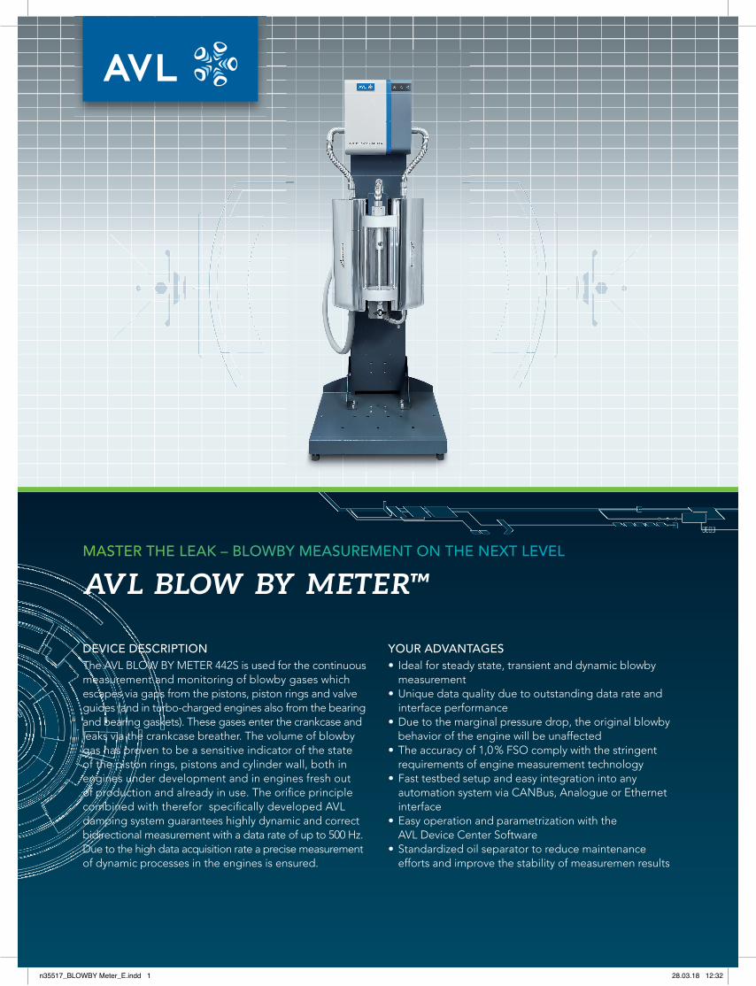
DEVICE DESCRIPTIONThe AVL BLOW BY METER 442S is used for the continuous measurement and monitoring of blowby gases which escapes via gaps from the pistons, piston rings and valve guides (and in turbo-charged engines also from the bearing and bearing gaskets). These gases enter the crankcase and leaks via the crankcase breather. The volume of blowby gas has proven to be a sensitive indicator of the state of the piston rings, pistons and cylinder wall, both in engines under development and in engines fresh out of production and already in use. The orifi ce principle combined with therefor specifi cally developed AVL damping system guarantees highly dynamic and correct bidirectional measurement with a data rate of up to 500 Hz. Due to the high data acquisition rate a precise measurement of dynamic processes in the engines is ensured.
YOUR ADVANTAGES• Ideal for steady state, transient and dynamic blowby
measurement• Unique data quality due to outstanding data rate and
interface performance • Due to the marginal pressure drop, the original blowby
behavior of the engine will be unaffected • The accuracy of 1,0 % FSO comply with the stringent
requirements of engine measurement technology• Fast testbed setup and easy integration into any
automation system via CANBus, Analogue or Ethernet interface
• Easy operation and parametrization with the AVL Device Center Software
• Standardized oil separator to reduce maintenance efforts and improve the stability of measuremen results
AVL BLOW BY METER™MASTER THE LEAK – BLOWBY MEASUREMENT ON THE NEXT LEVEL
n35517_BLOWBY Meter_E.indd 1 28.03.18 12:32
CUSTOMER REQUIREMENTSBlowby measurement nowadays is standard on enginetest beds. To be able to comply with the emission leg-islation for new combustion engines today and in the future, the requirements for crankcase ventilation systems will continue to increase. The necessity of continuous measurement of the blowby fl ow to monitor the engine condition make the AVL BLOW BY METER 442S an indis-pensable instrument for engine testing.
APPLICATIONOn the basis of the interchangeable measurement ranges between 0,2 and 2,400 l/min, the AVL BLOW BY METER 442S can be used from small-scale and single-cylinder engines up to diesel engines for ships. The areas of ap-plication cover engine research and optimization of the piston-cylinder assembly, furthermore this system is used when designing crankcase ventilation systems and on quality and endurance testbeds. The devcie easily can be integrated via CANBus, Analogue or Ethernet interface.Standardized oil seperator ensure reduced maintenance efforts, along with the mobile on-site calibration service a high device availability is guaranteed.
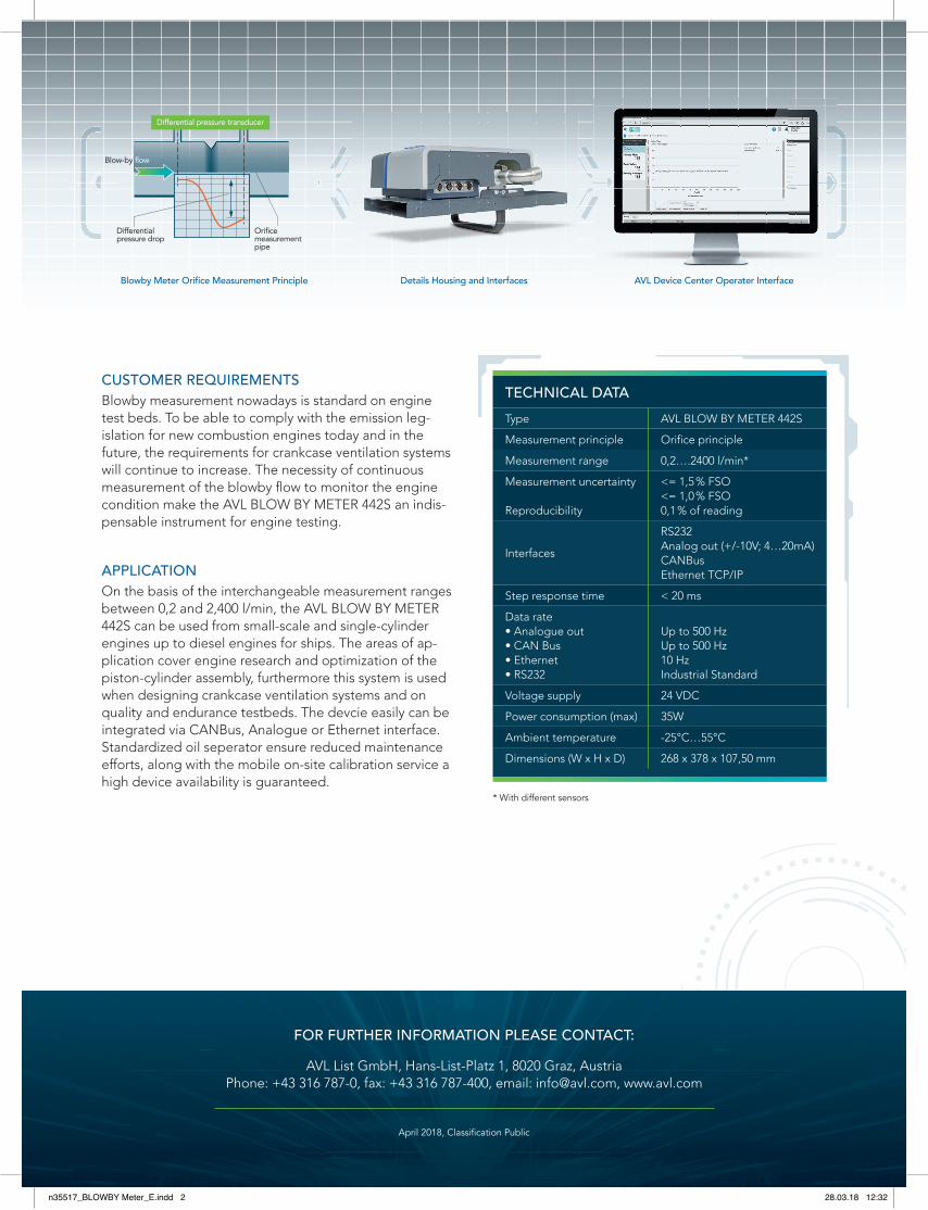
Details Housing and InterfacesBlowby Meter Orifi ce Measurement Principle AVL Device Center Operater Interface
FOR FURTHER INFORMATION PLEASE CONTACT:
AVL List GmbH, Hans-List-Platz 1, 8020 Graz, AustriaPhone: +43 316 787-0, fax: +43 316 787-400, email: [email protected], www.avl.com
April 2018, Classifi cation Public
TECHNICAL DATAType AVL BLOW BY METER 442S
Measurement principle Orifi ce principle
Measurement range 0,2….2400 l/min*
Measurement uncertainty
Reproducibility
<= 1,5 % FSO<= 1,0 % FSO0,1 % of reading
Interfaces
RS232Analog out (+/-10V; 4…20mA)CANBusEthernet TCP/IP
Step response time < 20 ms
Data rate• Analogue out• CAN Bus• Ethernet • RS232
Up to 500 HzUp to 500 Hz10 HzIndustrial Standard
Voltage supply 24 VDC
Power consumption (max) 35W
Ambient temperature -25°C…55°C
Dimensions (W x H x D) 268 x 378 x 107,50 mm
Differentialpressure drop
Orificemeasurementpipe
Blow-by flow
Differential pressure transducer
* With different sensors
n35517_BLOWBY Meter_E.indd 2 28.03.18 12:32


![VIP Escapes [Chinese]](https://img.pdfslide.net/doc/110x75/579071171a28ab6874a083da/vip-escapes-chinese.jpg)