Embed Size (px)
Citation preview

Appareillage basse tension Low voltage switchgear
Masterpact NW 800-6300 A
Fiche technique / Technical data sheet
2009
La gamme de disjoncteurs de puissance Masterpact NW assure la protection des circuits de forte puissance et des récepteurs :
intensité nominale de 800 A à 6300 Avolume unique de 800 A à 4000 Atri et tétrapolairesappareil fixe ou débrochable4 types de protection électronique RMS en standardlong retard réglable de 0,4 à 1 In par crans ou par clavier, en local ou à distancetension d'emploi jusqu'à 690 V CApouvoir de coupure de 42 à 150 kA sous 220/415 V CAvariantes interrupteur NA, HA, HA10, et HFdes fonctions électroniques dédiées à la gestion d'énergie et à l'analyse de réseauxalimentation par le haut et par le basmécanisme à accumulation d'énergie pour fermeture de l'appareil (synchro-couplage).
Une gamme d'accessoires et d'auxiliaires électriques complète :interverrouillage pour inverseur de source manuel ou automatique 2 ou 3 Masterpactmoteur de réarmementdéclencheur à minimum de tension (MN, MNR)déclencheur à émission de courant (MX)electro-aimant de fermeture (XF)contacts auxiliaires (OF, SDE, PF, etc.)bouton poussoir de fermeture électrique BPFEverrouillage par cadenas et/ou par clés.
La gamme Masterpact NW est conforme aux principales normes et homologations :
IEC 60947-1 - 60947-2 et 60947-3IEC 68230 pour la tropicalisation de type 2variantes UL 489 et UL 1066 voir documentation spécifique.
The Masterpact NW range of power circuit breakers protects circuits and loads:
rated current from 800 A to 6300 Aone frame size from 800 A to 4000 A3 and 4-pole modelsfixed or drawout versions4 types of electronic protections featuring rms measurement as standardadjustable long-time settings from 0.4 to 1 In, with fine adjustment via local keypad
or remote supervisoroperational voltage up to 690 V ACbreaking capacity from 42 to 150 kA at 220/415 V ACMasterpact type NA, HA, HA10 and HF switch-disconnector versionselectronic functions dedicated to energy management and power-quality analysisreverse feed possiblestored-energy mechanism for instantaneous closing (source coupling).
A complete range of electrical accessories and auxiliaries:automatic and manual source-changeover systems for 2 or 3 Masterpact devicesmotor mechanismundervoltage release (MN, MNR)shunt trip unit (MX)closing release (XF)auxiliary contacts (OF, SDE, PF, etc.)electrical closing buttonlocking by padlocks and/or keylocks.
The Masterpact NW range complies with main standards and certifications:
IEC 60947-1 - 60947-2 and 60947-3IEC 68230 for type 2 tropicalizationUL 489 and UL 1066 versions, refer to specific documentation.
bbbbbbbbbbbb
bbbbbbbb
bbb
bbbbbb
bbbbbb
bbbbbbbb
bbb
PB
1043
83A
60
NW08 à / to NW63
2
Un maximum de sécuritéIl possède en standard :
la coupure pleinement apparenteune tenue de tension aux chocs électriques élevée
(12 kV)la fonction sectionnement conformément à la norme
IEC 60947-2 et porte en face avant le symbole "disjoncteur sectionneur"
l'isolation de classe 2 de la face avant, permettant une installation de classe 2 avec commande du disjoncteur à travers porte.Pour des caractéristiques ou fonctionnalités plus complètes consulter le catalogue général.
bb
b
b
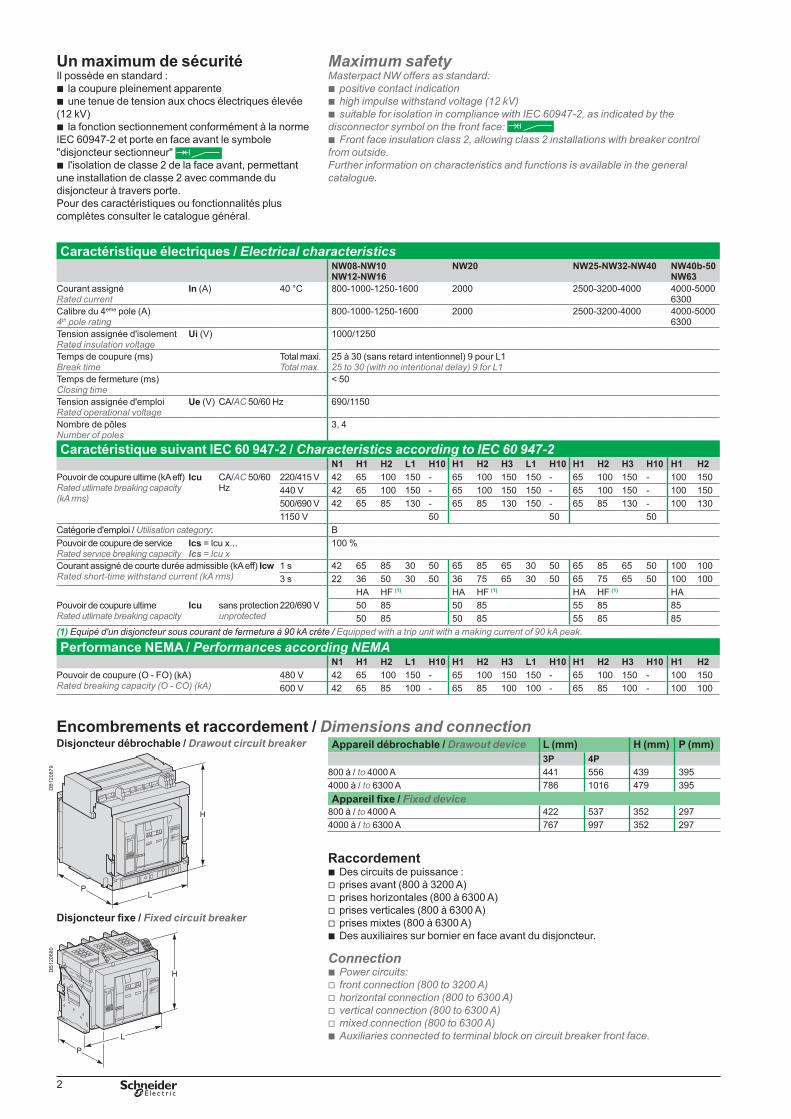
Encombrements et raccordement / Dimensions and connectionAppareil débrochable / Drawout device L (mm) H (mm) P (mm)
3P 4P800 à / to 4000 A 441 556 439 3954000 à / to 6300 A 786 1016 479 395Appareil fixe / Fixed device
800 à / to 4000 A 422 537 352 2974000 à / to 6300 A 767 997 352 297
RaccordementDes circuits de puissance :prises avant (800 à 3200 A)prises horizontales (800 à 6300 A)prises verticales (800 à 6300 A)prises mixtes (800 à 6300 A)Des auxiliaires sur bornier en face avant du disjoncteur.
ConnectionPower circuits:front connection (800 to 3200 A)horizontal connection (800 to 6300 A)vertical connection (800 to 6300 A)mixed connection (800 to 6300 A)Auxiliaries connected to terminal block on circuit breaker front face.
bvvvvb
bvvvvb
DB
1208
79
Disjoncteur débrochable / Drawout circuit breaker
����������
�������� ��������
�
�����
���
����������
������������������
������������������
������
����������
��������������������������
�����������
��
������������
�
��
Disjoncteur fixe / Fixed circuit breaker
�����������
��
������������
����������
�������� ��������
�
�����
���
����������
������������������
������������������
������
����������
��������������������������
�
�
�
DB
1208
80
Caractéristique électriques / Electrical characteristicsNW08-NW10NW12-NW16
NW20 NW25-NW32-NW40 NW40b-50NW63
Courant assigné Rated current
In (A) 40 °C 800-1000-1250-1600 2000 2500-3200-4000 4000-5000 6300
Calibre du 4eme pole (A)4th pole rating
800-1000-1250-1600 2000 2500-3200-4000 4000-5000 6300
Tension assignée d'isolement Rated insulation voltage
Ui (V) 1000/1250
Temps de coupure (ms)Break time
Total maxi.Total max.
25 à 30 (sans retard intentionnel) 9 pour L125 to 30 (with no intentional delay) 9 for L1
Temps de fermeture (ms) Closing time
< 50
Tension assignée d'emploi Rated operational voltage
Ue (V) CA/AC 50/60 Hz 690/1150
Nombre de pôles Number of poles
3, 4
Caractéristique suivant IEC 60 947-2 / Characteristics according to IEC 60 947-2N1 H1 H2 L1 H10 H1 H2 H3 L1 H10 H1 H2 H3 H10 H1 H2
Pouvoir de coupure ultime (kA eff) Rated utlimate breaking capacity (kA rms)
Icu CA/AC 50/60 Hz
220/415 V 42 65 100 150 - 65 100 150 150 - 65 100 150 - 100 150440 V 42 65 100 150 - 65 100 150 150 - 65 100 150 - 100 150500/690 V 42 65 85 130 - 65 85 130 150 - 65 85 130 - 100 1301150 V 50 50 50
Catégorie d'emploi / Utilisation category: BPouvoir de coupure de serviceRated service breaking capacity
Ics = lcu x...Ics = lcu x
100 %
Courant assigné de courte durée admissible (kA eff) IcwRated short-time withstand current (kA rms)
1 s 42 65 85 30 50 65 85 65 30 50 65 85 65 50 100 1003 s 22 36 50 30 50 36 75 65 30 50 65 75 65 50 100 100
HA HF (1) HA HF (1) HA HF (1) HAPouvoir de coupure ultimeRated utlimate breaking capacity
Icu sans protectionunprotected
220/690 V 50 85 50 85 55 85 8550 85 50 85 55 85 85
(1) Equipé d'un disjoncteur sous courant de fermeture à 90 kA crête / Equipped with a trip unit with a making current of 90 kA peak.
Performance NEMA / Performances according NEMAN1 H1 H2 L1 H10 H1 H2 H3 L1 H10 H1 H2 H3 H10 H1 H2
Pouvoir de coupure (O - FO) (kA)Rated breaking capacity (O - CO) (kA)
480 V 42 65 100 150 - 65 100 150 150 - 65 100 150 - 100 150600 V 42 65 85 100 - 65 85 100 100 - 65 85 100 - 100 100
Maximum safetyMasterpact NW offers as standard:
positive contact indicationhigh impulse withstand voltage (12 kV)suitable for isolation in compliance with IEC 60947-2, as indicated by the
disconnector symbol on the front face: Front face insulation class 2, allowing class 2 installations with breaker control
from outside.Further information on characteristics and functions is available in the general catalogue.
bbb
b
3
Choix des unités de contrôle / Selection of control units Protection en courant / Current protection2 = LR, Inst / LT, Inst5 = protection sélective LR, CR, Inst / LT, ST, Inst selective protection6 = protection sélective + terre / selective + earth-fault protection7 = protection sélective + Vigi / selective + earth-leakage protection
.0 = 1re génération / 1st generation
Mesures et autres protectionsA = Ampèremètre numérique
I1, I2, I3, IN, Iterre, Idifférentiel et maximètres de ces mesuresSignalisation des défautsValeurs des réglages en ampères et secondes.
P = A + puissance + protections paramétrablesMesures V, A, W, VAR, VA, Wh, VARh, VAh, Hz, V, A, facteur de puissance,
maximètres et minimètresProtections long retard en IDMTL, minimum et maximum en tension et fréquence,
déséquilibres en tension et courant, sens de rotation des phases, retour de puissanceDélestage/relestage en fonction de la puissance ou du courantMesures des courants coupés, signalisation différentiée de défaut, indicateurs de
maintenance, datation et historique d’événements.H = P + harmoniques
Qualité de l’énergie : fondamentaux, taux de distorsion, amplitude et phase des harmoniques jusqu’au rang harmonique 31
Capture d’ondes sur défaut, alarme ou à la demandeAlarmes programmables : seuils et actions programmables sur mesure
Measurements and other protectionA = Digital ammeter
I1, I2, I3, IN, Ig, IDn and maximeters for each measurement Fault indicationsSettings displayed in amperes and seconds.
P = A + power meter + adjustable protection parametersV, A, W, VAR, VA, Wh, VARh, VAh, Hz, power factor, maximeters and minimetersIDMTL long-time protection, minimum and maximum voltage and frequency,
current and voltage imbalance, reverse power, phase sequenceLoad shedding and reconnection as a function of current or powerMeasurement of interrupted currents, differentiated fault indications, maintenance
indicators, event time-stamping and histories, etc.H = P + harmonic meter
Power quality: fundamentals, distortion, amplitude and phase of harmonics up to 31st order
Waveform capture after fault or alarm or on requestProgrammable alarms: custom thresholds and actions, etc.
Exemple / Example:Micrologic 5.0 AUnité de contrôle Micrologic avec protection sélective (5), de 1re génération (.0), avec ampèremètre numérique, mesure de puissance et protections paramétrables (A).Micrologic 5.0 AMicrologic control unit with selective (LT, ST, Inst) protection (5), first generation (.0) with digital ammeter, power measurements and adjustable protection functions (A).
bbb
b
b
bb
b
bb
bbb
bb
bb
b
bb
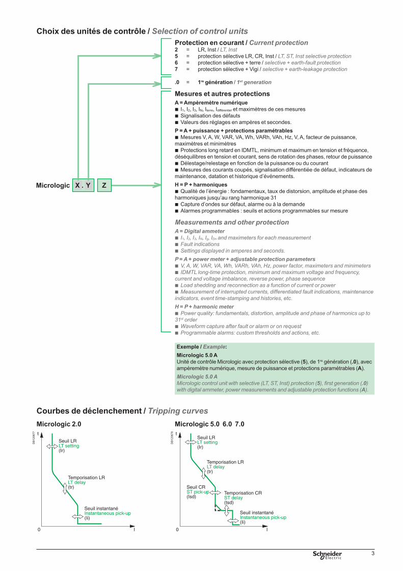
Courbes de déclenchement / Tripping curves
DB
1208
77
Micrologic 2.0
� �
�
����������������������
�����������������������������������������
����������������������������
DB
1208
78
Micrologic 5.0 6.0 7.0
� �
�����������������������
�����������������������
�����������������������������
�����������������������������������������
����������������������������

03-2009COMBT07
CO
MB
T07
© 2
009
- Sch
neid
er E
lect
ric -
All
right
s re
serv
ed.
Schneider Electric Industries SAS35, rue Joseph MonierCS 30323F- 92506 Rueil Malmaison Cedex
RCS Nanterre 954 503 439Capital social 896 313 776 €www.schneider-electric.com
As standards, specifications and designs change from time to time, please ask for confirmation of the information given in this publication.
This document has been printed on ecological paper
Designed: Schneider ElectricPhotos: Schneider Electric
Unité de contrôle - Caractéristiques techniques / Control units - Technical characteristicsMicrologic 2.0 5.0 6.0 7.0Protection long retard / Long-time protection b b b bSeuil (A) / Current setting (A) Ir = In x … 0.4 0.5 0.6 0.7 0.8 0.9 0.95 0.98 1
Déclenchement entre 1.05 à 1.20 IrTripping between 1.05 and 1.20 Ir
Autres plages ou inhibition par changement de plugOther ranges or disable by changing rating plug
Temporisation (s)Time delay (s)
tr à / at 1.5 x Ir 12.5 25 50 100 200 300 400 500 600
Précision : 0 à -20 %Accuracy: 0 to -20%
tr à / at 6 x Ir 0,7 (1) 1 2 4 8 12 16 20 24tr à / at 7.2 x Ir 0,7 (2) 0.69 1.38 2.7 5.5 8.3 11 13.8 16.6
Mémoire thermique / Thermal memory 20 mn avant et après déclenchement / 20 mn before and after tripping(1) 0 à / to - 40 % - (2) 0 à / to - 60 %Protection court retard / Short-time protection b b bSeuil (A) / Pick-up (A) Isd = Ir x … 1.5 2 2.5 3 4 5 6 8 10
Précision / Accuracy ± 10 %Réglage temporisation (s) / Time settings (s)Crans de réglage / Settings I2t Off 0 0.1 0.2 0.3 0.4
I2t On 0.1 0.2 0.3 0.4Temporisation (ms) à 10 Ir /Time delay (ms) at 10 Ir
tsd (non déclenchement) (max resettable time)
20 80 140 230 350
tsd (max de coupure)(max. break time)
80 140 200 320 500
Protection instantanée / Instantaneous protection b b b
Seuil (A) / Pick-up (A) Ii = In x … 2 3 4 6 8 10 12 15 offPrécision / Accuracy ± 10 %Seuil (A) / Pick-up (A) Isd = Ir x … b
1.5 2 2.5 3 4 5 6 8 10Temporisation / Time delay Temps de non déclenchement : 20 ms / max resettable time : 20 ms
Temps max de coupure : 50 ms / max break time : 50 msProtection terre / Earth-fault protection bSeuil (A) / Pick-up (A)
Ig = In x … A B C D E F G H JIn y 400 A 0.3 0.3 0.4 0.5 0.6 0.7 0.8 0.9 1400 A < In < 1250 A 0.2 0.3 0.4 0.5 0.6 0.7 0.8 0.9 1In u 1250 A 500 640 720 800 880 960 1040 1120 1200
Précision / Accuracy ± 10 %Réglage temporisation (s) / Time settings (s)Crans de réglage / Settings I2t Off 0 0.1 0.2 0.3 0.4
I2t On 0.1 0.2 0.3 0.4Temporisation (ms)à In ou 1200 ATime delay (ms)at In or 1200A
tg (non déclenchement) (max resettable time)
20 80 140 230 350
tg (max de coupure) (max. break time)
80 140 200 320 500
Protection différentielle / Earth-leakage protection bSensibilité (A) / Sensitivity (A) IDn 0.5 1 2 3 5 7 10 20 30Précision / Accuracy 0 à / to -20 %Temporisation (ms)Time delay (ms)
Cran de réglage / Settings 60 140 230 350 800Dt (non déclenchement)
(max resettable time)60 140 230 350 800
Dt (max de coupure)(max. break time)
140 200 320 500 1000
CommunicationL'intégration du disjoncteur ou de l'interrupteur dans un système de supervision nécessite un module de communication installé derrière l'unité de contrôle. Une liaison par bus permet suivant le type d'unité de contrôle et d'appareil :
l'identification de l'appareilla signalisation des états de l'appareilla commande de l'appareille paramétrage :des protections en courant (LR, CR, I, Terre, vigi)des protections additionnelles (IDMTL, Min/Max
fréquence, courant tension, etc.)des alarmes personnalisables (seuil haut et bas
associés à chaque mesure avec paramétrage de l'action en cas de dépassement).
la transmission de données d'aide à l'exploitation et à la maintenance (lecture des réglages, de l'ensemble des mesures et indicateurs calculés, forme d'onde, historique et journaux, registre de maintenance). Masterpact s'intègre totalement dans le système Digipact ou dans un réseau Modbus.
bbbbvv
v
b
CommunicationMasterpact circuit breakers or switch-disconnectors can be integrated in a supervision system by fitting a communication module behind the control unit. Depending on the type of device and control unit, a bus-type link may be used to:
identify the deviceindicate device statuscontrol the deviceset parameters for:current protection (LT, ST, Inst, earth fault, earth leakage)additional protection functions (IDMTL, under/over frequency, current, voltage,
etc.)programmable alarms (high and low thresholds for each measurement and
selection of the action to be taken in the event of an overrun)transmit operating and maintenance-aid data (settings, calculated indications and
measurements, waveform capture, histories and logs, maintenance records). Masterpact devices are fully compatible with the Digipact system or with a Modbus network.
bbbbvv
v
b