Embed Size (px)
Citation preview

Introduction
Mate Precision Tooling is the world’s leading manufacturer of NC punch press tooling. Our onlybusiness is punch press tooling. Our five decades of specialization and expertise have earned us aworldwide reputation of top quality products, fast delivery, competitive prices and customersatisfaction.
Purpose
The purpose of this tooling manual is to explain in detail the processes involved in making holesand making forms in sheet metal. It was designed to accompany the Mate Precision ToolingULTRA® Tooling Catalog. This manual explains methods for producing higher quality sheet metalproducts.
Mate Precision Tooling
mate.com1295 Lund Boulevard
Anoka, Minnesota 55303 USAPhone 800-328-4492 • 763-421-0230
Fax 800-541-0285 • 763-421-0285
Tooling Manual forPunch Presses Using
Thick Turret Style Tooling
1 © 2001 Mate Precision Tooling

Table of Contents
Introduction . . . . . . . . . . . . . . . . . . . . . . . . . . . . . . . . . . . . . . . . . . . . . . . . . . . 1
I. The Perforation Process . . . . . . . . . . . . . . . . . . . . . . . . . . . . . . . . . . . . . . . . . 5Hole Punching Process . . . . . . . . . . . . . . . . . . . . . . . . . . . . . . . . . . . . . . . . . . . . . . . . . . . . 5What do Your Slugs Tell You? . . . . . . . . . . . . . . . . . . . . . . . . . . . . . . . . . . . . . . . . . . . . . . . . 6Anatomy of a Punched Hole . . . . . . . . . . . . . . . . . . . . . . . . . . . . . . . . . . . . . . . . . . . . . . . . 6Punching Force Over Time . . . . . . . . . . . . . . . . . . . . . . . . . . . . . . . . . . . . . . . . . . . . . . . . . 7Proper vs. Tight Clearance. . . . . . . . . . . . . . . . . . . . . . . . . . . . . . . . . . . . . . . . . . . . . . . . . . 8Die Clearance – Benefits. . . . . . . . . . . . . . . . . . . . . . . . . . . . . . . . . . . . . . . . . . . . . . . . . . . 9Insufficient Die Clearance . . . . . . . . . . . . . . . . . . . . . . . . . . . . . . . . . . . . . . . . . . . . . . . . . 10Excessive Die Clearance . . . . . . . . . . . . . . . . . . . . . . . . . . . . . . . . . . . . . . . . . . . . . . . . . . 10Anatomy of a Punched Hole . . . . . . . . . . . . . . . . . . . . . . . . . . . . . . . . . . . . . . . . . . . . . . . 10Die Clearance Chart . . . . . . . . . . . . . . . . . . . . . . . . . . . . . . . . . . . . . . . . . . . . . . . . . . . . . 11
II. Tonnage . . . . . . . . . . . . . . . . . . . . . . . . . . . . . . . . . . . . . . . . . . . . . . . . . . . 12Tonnage Calculation . . . . . . . . . . . . . . . . . . . . . . . . . . . . . . . . . . . . . . . . . . . . . . . . . . . . . 12Directions and Examples. . . . . . . . . . . . . . . . . . . . . . . . . . . . . . . . . . . . . . . . . . . . . . . . . . 13Dimension Chart for Tonnage Calculation . . . . . . . . . . . . . . . . . . . . . . . . . . . . . . . . . . . . . 14
III. ULTRA TEC® Tooling System. . . . . . . . . . . . . . . . . . . . . . . . . . . . . . . . . . . . 15Standard Shapes . . . . . . . . . . . . . . . . . . . . . . . . . . . . . . . . . . . . . . . . . . . . . . . . . . . . . . . . 16Ordering . . . . . . . . . . . . . . . . . . . . . . . . . . . . . . . . . . . . . . . . . . . . . . . . . . . . . . . . . . . . . 16ULTRA TEC® Tooling System Highlights . . . . . . . . . . . . . . . . . . . . . . . . . . . . . . . . . . . . . 17-18Recommended Stripper Lead. . . . . . . . . . . . . . . . . . . . . . . . . . . . . . . . . . . . . . . . . . . . . . . 18Angle Settings. . . . . . . . . . . . . . . . . . . . . . . . . . . . . . . . . . . . . . . . . . . . . . . . . . . . . . . . . . 19ULTRA TEC® A Station/ULTRA TEC® B Station . . . . . . . . . . . . . . . . . . . . . . . . . . . . . . . . . . . 20ULTRA TEC® C, D, and E Station . . . . . . . . . . . . . . . . . . . . . . . . . . . . . . . . . . . . . . . . . . . . 21Dies – All Stations. . . . . . . . . . . . . . . . . . . . . . . . . . . . . . . . . . . . . . . . . . . . . . . . . . . . . . . 22Grind Life. . . . . . . . . . . . . . . . . . . . . . . . . . . . . . . . . . . . . . . . . . . . . . . . . . . . . . . . . . . . . 23Installation/Length Adjustment A Station . . . . . . . . . . . . . . . . . . . . . . . . . . . . . . . . . . . . . . 24Installation/Length Adjustment B Station. . . . . . . . . . . . . . . . . . . . . . . . . . . . . . . . . . . . . . . 25Installation/Length Adjustment C, D, E Station . . . . . . . . . . . . . . . . . . . . . . . . . . . . . . . . . . 26Maximum Material Thickness Recommendations . . . . . . . . . . . . . . . . . . . . . . . . . . . . . . . . 27
IV. ULTRA TEC® Fully Guided . . . . . . . . . . . . . . . . . . . . . . . . . . . . . . . . . . . . . 28Stations . . . . . . . . . . . . . . . . . . . . . . . . . . . . . . . . . . . . . . . . . . . . . . . . . . . . . . . . . . . . . . 28Features . . . . . . . . . . . . . . . . . . . . . . . . . . . . . . . . . . . . . . . . . . . . . . . . . . . . . . . . . . . . . . 28Fully Guided Clamp Clearing . . . . . . . . . . . . . . . . . . . . . . . . . . . . . . . . . . . . . . . . . . . . . . 29Slitting Tools . . . . . . . . . . . . . . . . . . . . . . . . . . . . . . . . . . . . . . . . . . . . . . . . . . . . . . . . . . . 29
© 2001 Mate Precision Tooling 2

V. Special Shapes . . . . . . . . . . . . . . . . . . . . . . . . . . . . . . . . . . . . . . . . . . . . . . 30Ordering . . . . . . . . . . . . . . . . . . . . . . . . . . . . . . . . . . . . . . . . . . . . . . . . . . . . . . . . . . . . . 30Tips and Helpful Hints . . . . . . . . . . . . . . . . . . . . . . . . . . . . . . . . . . . . . . . . . . . . . . . . . 30-32Mate Special Shapes – Illustrations . . . . . . . . . . . . . . . . . . . . . . . . . . . . . . . . . . . . . . . . . . 33Maximum Station Ranges . . . . . . . . . . . . . . . . . . . . . . . . . . . . . . . . . . . . . . . . . . . . . . . . . 33
VI. Special Assemblies . . . . . . . . . . . . . . . . . . . . . . . . . . . . . . . . . . . . . . . . . . 34Ordering . . . . . . . . . . . . . . . . . . . . . . . . . . . . . . . . . . . . . . . . . . . . . . . . . . . . . . . . . . . . . 34General Considerations. . . . . . . . . . . . . . . . . . . . . . . . . . . . . . . . . . . . . . . . . . . . . . . . . . . 34ULTRAFORM® Assemblies . . . . . . . . . . . . . . . . . . . . . . . . . . . . . . . . . . . . . . . . . . . . . . . . . 35Clusters and Fully Guided Clusters . . . . . . . . . . . . . . . . . . . . . . . . . . . . . . . . . . . . . . . . . . 36Helpful Hints. . . . . . . . . . . . . . . . . . . . . . . . . . . . . . . . . . . . . . . . . . . . . . . . . . . . . . . . 37-39Mate Sheetmarker™ . . . . . . . . . . . . . . . . . . . . . . . . . . . . . . . . . . . . . . . . . . . . . . . . . . . . . 40Mate Rollerball® . . . . . . . . . . . . . . . . . . . . . . . . . . . . . . . . . . . . . . . . . . . . . . . . . . . . . . . . 40
VII. Special Applications . . . . . . . . . . . . . . . . . . . . . . . . . . . . . . . . . . . . . . . . 41Punching Thick Material (over 4mm) . . . . . . . . . . . . . . . . . . . . . . . . . . . . . . . . . . . . . . . . . 42ULTRA® Heavy Duty Tooling Advantages . . . . . . . . . . . . . . . . . . . . . . . . . . . . . . . . . . . . . . 42Punching Non-Metallic Material . . . . . . . . . . . . . . . . . . . . . . . . . . . . . . . . . . . . . . . . . . . . 42Blanking Operations . . . . . . . . . . . . . . . . . . . . . . . . . . . . . . . . . . . . . . . . . . . . . . . . . . . . . 43Small Diameter or Narrow Holes. . . . . . . . . . . . . . . . . . . . . . . . . . . . . . . . . . . . . . . . . . . . 44Ratio of Punch to Material Thickness . . . . . . . . . . . . . . . . . . . . . . . . . . . . . . . . . . . . . . . . . 44Recommended Minimum Distances . . . . . . . . . . . . . . . . . . . . . . . . . . . . . . . . . . . . . . . . . 45
VIII. Treatments and Coatings . . . . . . . . . . . . . . . . . . . . . . . . . . . . . . . . . . . . . 46Nitride Treatment . . . . . . . . . . . . . . . . . . . . . . . . . . . . . . . . . . . . . . . . . . . . . . . . . 46Maxima™ Coating . . . . . . . . . . . . . . . . . . . . . . . . . . . . . . . . . . . . . . . . . . . . . . . . 46
IX. Punch Shear . . . . . . . . . . . . . . . . . . . . . . . . . . . . . . . . . . . . . . . . . . . . . . . 47Advantages of Shear . . . . . . . . . . . . . . . . . . . . . . . . . . . . . . . . . . . . . . . . . . . . . . . 47Common types of Shear . . . . . . . . . . . . . . . . . . . . . . . . . . . . . . . . . . . . . . . . . . . . 47Punching Force Considerations . . . . . . . . . . . . . . . . . . . . . . . . . . . . . . . . . . . . . . . 48
X. Maintenance . . . . . . . . . . . . . . . . . . . . . . . . . . . . . . . . . . . . . . . . . . . . . . . 49Benefits . . . . . . . . . . . . . . . . . . . . . . . . . . . . . . . . . . . . . . . . . . . . . . . . . . . . . . . . 49Torque Recommendations . . . . . . . . . . . . . . . . . . . . . . . . . . . . . . . . . . . . . . . . . . . 49Sharpening Rules . . . . . . . . . . . . . . . . . . . . . . . . . . . . . . . . . . . . . . . . . . . . . . . . . 49When to Sharpen Punches. . . . . . . . . . . . . . . . . . . . . . . . . . . . . . . . . . . . . . . . . . . 50Die Maintenance . . . . . . . . . . . . . . . . . . . . . . . . . . . . . . . . . . . . . . . . . . . . . . . . . 50Importance of Frequent Tool Maintenance . . . . . . . . . . . . . . . . . . . . . . . . . . . . . . . 50Tool Maintenance Tips. . . . . . . . . . . . . . . . . . . . . . . . . . . . . . . . . . . . . . . . . . . . . . 51Factors Affecting Tool Wear . . . . . . . . . . . . . . . . . . . . . . . . . . . . . . . . . . . . . . . . . . 52Minimum Punch Lengths. . . . . . . . . . . . . . . . . . . . . . . . . . . . . . . . . . . . . . . . . . . . 53Minimum Die Height . . . . . . . . . . . . . . . . . . . . . . . . . . . . . . . . . . . . . . . . . . . . . . 53
3 © 2001 Mate Precision Tooling

XI. Troubleshooting. . . . . . . . . . . . . . . . . . . . . . . . . . . . . . . . . . . . . . . . . . . . . 54Excessive Burrs . . . . . . . . . . . . . . . . . . . . . . . . . . . . . . . . . . . . . . . . . . . . . . . . . . . 54Poor Hole Quality. . . . . . . . . . . . . . . . . . . . . . . . . . . . . . . . . . . . . . . . . . . . . . . . . 54Punch Breakage . . . . . . . . . . . . . . . . . . . . . . . . . . . . . . . . . . . . . . . . . . . . . . . . . . 54Punch Does Not Strip . . . . . . . . . . . . . . . . . . . . . . . . . . . . . . . . . . . . . . . . . . . . . . 54Punch Galling. . . . . . . . . . . . . . . . . . . . . . . . . . . . . . . . . . . . . . . . . . . . . . . . . . . . 54Punch Sticking in Work Piece . . . . . . . . . . . . . . . . . . . . . . . . . . . . . . . . . . . . . . . . 54Rapid Tool Wear . . . . . . . . . . . . . . . . . . . . . . . . . . . . . . . . . . . . . . . . . . . . . . . . . . 55Sheet Accuracy . . . . . . . . . . . . . . . . . . . . . . . . . . . . . . . . . . . . . . . . . . . . . . . . . . . 55Slug Pulling . . . . . . . . . . . . . . . . . . . . . . . . . . . . . . . . . . . . . . . . . . . . . . . . . . . . . 55Surface Cracks on Face of Punch . . . . . . . . . . . . . . . . . . . . . . . . . . . . . . . . . . . . . . 55Warpage of Work Piece. . . . . . . . . . . . . . . . . . . . . . . . . . . . . . . . . . . . . . . . . . . . . 55Work Piece Marking . . . . . . . . . . . . . . . . . . . . . . . . . . . . . . . . . . . . . . . . . . . . . . . 55
XII. Tips and Techniques . . . . . . . . . . . . . . . . . . . . . . . . . . . . . . . . . . . . . . . . . 56Do’s and Don’ts of Punching . . . . . . . . . . . . . . . . . . . . . . . . . . . . . . . . . . . . . . . . . 56Helpful Tips . . . . . . . . . . . . . . . . . . . . . . . . . . . . . . . . . . . . . . . . . . . . . . . . . . . 57-61
XIII. Glossary . . . . . . . . . . . . . . . . . . . . . . . . . . . . . . . . . . . . . . . . . . . . . . 62-69
© 2001 Mate Precision Tooling 4

I. The Perforation Process
Hole Punching Process
Punching holes on a CNC punch press is a very productive and efficient way to produce holes insheet metal. It appears to be a simple process, although many variables greatly affect the quality ofthe piece part and the life of the tooling.
ULTRA TEC® 1 1/4" B Station Assembly
The following sequence visually describes the process of the punch impacting the sheet metal andthe slug passing through the Slug Free® die.
Dimensions in inches (millimeters) 5 © 2001 Mate Precision Tooling
aaaaaaaaaaaaaaaaaaaaaaaaaaaaaaaaaaaaaaa ®aaaaaaaaaaaaaaaaaaaaaaaaaaaaaaaaaaaaaaaaaaaaaaaaaaaaaaaaaaaaaaaaaaaaaaaaaaaaaaaaaaaaaaaaaaaaaaaaaaaaaaaaaaaaaaaaaaaaaaaaaaaaaaaaaaaaaMaterial held securelyby stripper before punchmakes contact.
Punch penetratesthe material. Slugfractures away fromsheet.
Pressure point constrictsslug. Punch strokebottoms out as slugsqueezes past pressurepoint.
Punch retracts and slugis free to fall down andaway through exit taperof the Slug Free® die.
Punch
Stripper
Material
Slug Free® Die

What Do Your Slugs Tell You?
The slug is essentially a mirror image of the hole with the same parts in reverse order. Byexamining your slugs, you can tell if punch-to-die clearance is correct, if tool angularity is correct,or if tooling is dull.
An ideal slug is created when the fracture planes coming from the top and bottom of the materialhave the same angle and form in alignment with each other. This keeps punching force to aminimum and forms a clean hole with little burr. When clearance is proper, tool life is extended.
If the clearance is too large, the slug will show a rough fracture plane (C) and a small burnish zone(B). The larger the clearance, the greater the angle between the fracture plane (C) and the burnishzone (B). Excess clearance makes a hole with large rollover (A) and fracture (C) so that the profileis somewhat pointed with a thin burr (D). When clearance is too large, tool life is reduced.
If clearance is too small, the slug will show a fracture plane (C) with little angle, and a largeburnish zone (B). Inadequate clearance makes a hole with small rollover (A) and steep fracture (C)so that the profile is more or less perpendicular to the surface of the material. When clearance istoo small, tool life is reduced.
Anatomy of a Punched Hole
1. Punch2. Stripper3. Material4. Slug Free® Die5. Slug6. Grind life7. Entry - Constricting taper8. Pressure point9. Exit - Relief taper
Hole/Slug Geometry
A. RolloverB. BurnishC. FractureD. Burr
See Die Clearance on page 10 for percent comparisons of slug characteristics.
© 2001 Mate Precision Tooling 6 Dimensions in inches (millimeters)
aaaaaaaaaaaaaaaaaaaaaaaaaaaaaaaaaaaaaaaaaaaaaaaaaaaa aaaaaaaaaaaaaaaaaaaaaaaaaaaaaa a aaaaaaaaaaa a aa aaaaaaaaaaaaaaaaaaaaaaaaaaaaaaaaaaaaaaaaaaaaaaaaaa aaaaaaaaaaaaaaaaaaaaaaaaaaaaaaaaaaaaaaaaaaaa a aaaaaaaaaaaaaaaaaaaaaaaaaaaaaaaaaaaaaaaaaaaaaaaaaaaaaaaaaaaaaaaaaaaaaaaaaaaaaaaaaaaaaaaD C
AB
7
8
9
ABC
D
2
3 1
45
aaaaaaaaaa6

Punching Force Over Time
M. Material held securely by stripper before punch makes contactA. Penetration / yield point / compressive forcesB. Maximum compressive and shear forceC. Fracture / "pure shear"D. Secondary shear break pointE. Secondary shearingF. Slug movementG. CompletedH. Stripping force
Dimensions in inches (millimeters) 7 © 2001 Mate Precision Tooling
Incr
easi
ng F
orce
Time

Proper vs. Tight Clearance
Why use proper die clearance?
Optimum clearance –Shear cracks join, balancing punching force, piece part quality and tool life.
Clearance too small –Secondary shear cracks are created, raising punching force and shortening tool life.
© 2001 Mate Precision Tooling 8 Dimensions in inches (millimeters)
PUNCH
DIE
MATERIAL
SHEAR CRACK
PUNCH
DIE
MATERIAL
SHEAR CRACK

Die Clearance
Die clearance is the difference in size between the punch dimensions and the die dimensions.Mate always refers to total die clearance rather than die clearance per side.
Dimensions in inches (millimeters) 9 © 2001 Mate Precision Tooling
PUNCH
DIE CLEARANCE
Die Clearance 2Die Clearance 1
DIEaaaaaaaaaaaaaaaaaaaaaaaaaaaaaaaaaaaaaaa ® Punch
Stripper
Material
Slug Free® Die
Benefits of PROPER
Die Clearance:
• Longer tool life.
• Better stripping.
• Smaller average burr height.
• Smaller average burr thickness.
• Cleaner, more uniform holes.
• Little or no shavings.
• Reduced galling.
• Flatter work pieces.
• More accurate hole locations.
• Lowest force required to pierce
the material.
Total Die Clearance =Die Clearance both sides of Punch
Total Die Clearance =Die Clearance 1 + Die Clearance 2

INSUFFICIENT Die Clearance: EXCESSIVE Die Clearance:
Die Clearance
© 2001 Mate Precision Tooling 10 Dimensions in inches (millimeters)
ANATOMY OF A PUNCHED HOLE
Rollover Depth - (RD)
Rollover Width - (RW)
Burnish Land - (BL)
MaterialThickness
(%)
Total Clearance - (TC)
Burr Height - (BH)
EFFECT OF TOTAL CLEARANCE AS A PERCENT (%) OF MATERIAL THICKNESS
TC10%15%25%35%
RD10%12%16%20%
RW50%40%45%50%
BH15%10%6%6%
BL75%55%50%45%
• Galling• Work piece shavings• Shortened tool life• Slow/erratic stripping• Poor hole quality• Excessive heat• Warped sheets• Smaller initial burr• Larger, thicker running burr• Quieter punching• Reduced rollover• Reduced break-away area• Reduced slug pulling• Work hardened burrs
• Increased slug pulling• Work piece shavings• Poor hole quality• Increased work piece distortion• Increased burr• Increased rollover• Increased breakaway area• Rounded slugs• Work hardened burrs

Die Clearance Chart
The information in this chart is a detailed version of general clearance charts that are published inMate Precision Tooling catalogs and in other industry publications.
The chart is also based on experiences from Mate customers who achieve superior piece partquality and the longest possible tool life.
Blanking tools are generally assigned with less clearance than piercing tools so that the burnishedarea of the piece part (slug) is greater. This leads to a higher quality piece part. Due to the smallerclearances, blanking tools may become dull more quickly.
Dimensions in inches (millimeters) 11 © 2001 Mate Precision Tooling
15%
20%
25%
20%
25%
30%
20%
25%
30%
35%
Material Thickness (T)
Less than .098 (2.50)
.098 (2.50) through .197 (5.00)
Greater than .197 (5.00)
Less than .118 (3.00)
.118 (3.00) through .236 (6.00)
Greater than .236 (6.00)
Less than .059 (1.50)
.059 (1.50) through .109 (2.77)
.110 (2.77) through .158 (4.00)
Greater than .158 (4.00)
Blanking
Total DieClearance(% of T)
Piercing
Total DieClearance(% of T)
Material Type(typical shear strength)
Aluminum25K psi (.1724kN/mm2)
Mild Steel50K psi (.3447kN/mm2)
Stainless Steel75K psi (.5171kN/mm2)
15%
15%
20%
15%
20%
20%
15%
20%
20%
25%

II. TonnageWhen punching thick materials or when punching materialswith a high tensile strength, caution must be observed not toexceed the recommended machine tonnage. Damage to themachine or the tooling could be the result in this situation.
Note: Some amount of tonnage is required for compressingthe springs in any spring tooling system. The amount isgreater in the larger stations than in the smaller stations.When nearing press capacity, contact your local Materepresentative or Mate customer service forrecommendations.
Tonnage CalculationTonnage Formula:
See example on following page.
PUNCHING FORCE CHANGES ASTOOLS BECOME DULL...
HEAVY TOOL WEAR
Sharp DullTool Sharpness
Punc
hing
For
ceO
ptim
alEx
cess
ive
May exceedmachinetonnage
capability
Dimensions in inches (millimeters) 12 © 2001 Mate Precision Tooling
Tonnage =Punch Perimeter x Material Thickness x Material Tonnage Value x Material Multiplier
Table 1MATERIAL TONNAGE VALUE
Metric (Metric Tons / mm2) Inch (Imperial Tons / in2)0.0352 25
Table 2MATERIAL TYPE MATERIAL MULTIPLIER
Aluminum (soft sheet) 0.3Aluminum (1/2 hard) 0.38Aluminum (full hard) 0.5Copper (rolled) 0.57Brass (soft sheet) 0.6Brass (1/2 hard) 0.7Mild Steel 1.0Stainless Steel 1.6

© 2001 Mate Precision Tooling 13 Dimensions in inches (millimeters)
Tonnage
Directions for Calculation:Calculate the tonnage using the Tonnage Formula. Equations for calculating the outside PunchPerimeter ("L" dimension) are found in the "Dimension Chart" on the following page. For theMaterial Tonnage Value (Table 1) and the Material Multiplier Value (Table 2), please reference theprevious page.
Example of Tonnage Calculation for a Square:
Example of Tonnage Calculation for a Round:
.787 (20.00) square, .118 (3.00) mild steel
Tonnage Formula:
Punch Perimeter x Material Thickness x Material Tonnage Value x Material Multiplier
.787 x .787(20.00 x 20.00) Square
.118 (3.00) Mild Steel
Tonnage = (4 x .787) x .118 x 25 x 1 = 9.28 Tons
Tonnage = (4 x 20) x 3 x .0352 x 1 = 8.45 Metric Tons
1.18 (30.00) diameter, .118 (3.00) aluminum
Tonnage Formula:
Punch Perimeter x Material Thickness x Material Tonnage Value x Material Multiplier
.118 (3.00) Aluminum
Tonnage = (3.14 x 1.18) x .118 x 25 x 0.5 = 5.47 Tons
Tonnage = (3.14 x 30) x 3 x .0352 x 0.5 = 4.97 Metric Tons
1.18 (30.00)diameter

Dimension Chart for Tonnage Calculation
Shape ‘A’ Dimension ‘L’ DimensionDictates Station Size Outside Perimeter
Round A = Diameter L = 3.14 x A
Square A = B x 1.414 L = 4 x B
Rectangle A = √ (B2 + C2) L = 2 x (B + C)
Oval A = C L = 2C + 1.14B
Rect / Oval A = √ (B2 + C2) L = 2C + 1.57B
Equilateral Triangle A = 1.334 x C L = 3 x B
Quad ‘D’ A = Diameter L = (approx.) 3.14 x A
Hexagon A = 1.155 x B L = 3 x A
Dimensions in inches (millimeters) 14 © 2001 Mate Precision Tooling

III. ULTRA TEC® Tooling System
ULTRA TEC® is a premium tooling system for thick turret style machines. It is a full line systemavailable for 1/2" A through 4 1/2" E stations.
ULTRA TEC® Station Ranges
Dimensions in inches (millimeters) 15 © 2001 Mate Precision Tooling
A .500 (12.70)B 1.250 (31.75)C 2.000 (50.80)D 3.500 (88.90)
E 4.500 (114.30)

Standard Shapes
In the ULTRA TEC® Tooling System, standard shapes include round, rectangle, oval, square, single Dand double D.
Round Rectangle Oval
Square Single ‘D’ Double ‘D’
When ordering tooling, customers should indicate the following:
• Tool style• Material type and thickness• Tool dimensions• Tool shape• Piercing or blanking• Non-standard features (if desired)• Special tolerances (if application is appropriate)
© 2001 Mate Precision Tooling 16 Dimensions in inches (millimeters)

ULTRA TEC® Tooling SystemULTRA TEC® is a complete system for both piercing and forming. The many features includepremium high speed steel (HSS) punches, Slug Free® dies, hardened guides with multiple anglesettings, interchangeability with other styles of thick turret tooling, extra grind life, quick lengthadjustment, and quick tool change capability. The ULTRAFORM® system for forming tools offers astandard holder design where forming inserts are quickly interchanged, and length adjustment isdone in .002 (0.05) increments.
Some ULTRA TEC® highlights include:
CanisterThe 1/2" A station canister is designed with high pressure Belleville disc springs. The 1 1/4" Bstation canister is designed with a special trapezoidal coil spring that assures even pressure andlong cycle life. The 2" C, 3 1/2" D, and 4 1/2" E station guides also use high pressure Belleville discsprings.
The 1/2" A station punch length is adjustable in .006 (0.15) increments. The 1 1/4" B station punchlength is adjustable in .008 (0.20) increments. The 2" C, 3 1/2" D and 4 1/2" E station guides punchlengths can be adjusted in .008 (0.20) increments.
PunchPunches are made from premium high speed tool steel (HSS). Standard back taper on original thickturret and ULTRA TEC® punches is 1/8° per side, 1/4° total. Lubrication grooves are standard on1/2" A and 1 1/4" B ULTRA TEC® punches.
Dimensions in inches (millimeters) 17 © 2001 Mate Precision Tooling
® ®
ULTRA TEC®
PUNCH GUIDE
ULTRA TEC®
STRIPPER PLATE
ULTRA TEC®
CANISTER ASSEMBLYSTANDARD
ULTRA TEC®
CANISTER ASSEMBLY
METRIC
STANDARDPUNCH
SLUG FREE®
DIE
® ® ®
ULTRA TEC®
CANISTER ASSEMBLYSTANDARD
ULTRA TEC®
PUNCH GUIDE
ULTRA TEC®
CANISTER ASSEMBLY
METRIC
ULTRA TEC®
CANISTER ASSEMBLY
INCH
INCH STYLEPUNCH
STANDARDPUNCH
ULTRA TEC®
PUNCH
SLUG FREE®
DIE
ULTRA TEC®
STRIPPER PLATE
®
®
ULTRA TEC®
GUIDE ASSEMBLYULTRA TEC®
GUIDE ASSEMBLY
ORIGINAL STYLEPUNCH BODY
ORIGINAL STYLEPUNCH BODY
ULTRA TEC®
STRIPPER PLATE
ULTRA TEC®
STRIPPER PLATE
SLUG FREE® DIESLUG FREE® DIE
ULTRA TEC®
PUNCH
A STATION C STATION D STATIONB STATION

GuideThe ULTRA TEC® hardened polished guide is designed with fluid through holes and external spirallubrication grooves for even and consistent lubrication between the tool and the turret bore. Mate hardenedguides are resistant to picking up small particles which cause marks on the guide and can be abrasive in theturret bore or tool holder.
The 1/2" A station shape guide has one external slot at 270°and three internal slots at 90°, 180° and 315°.
The 1/2" A station round guide has one internal and oneexternal slot designed to accept diameter punches.
The 1 1/4" B station shape guide has one external slot at 270°and five internal slots at 0°, 90°, 180°, 225° and 270°.
The 1 1/4" B station round guide has one internal and oneexternal slot designed to accept diameter punches.
StripperThe slide-in stripper has .008 (0.20) total clearance to punch point (.002 [0.05] when any punch dimensionis smaller than .125 [3.18]).
The .118 (3.00) relief in the A and B station strippers, .078 (2.00) inthe C, D and E station, increases grind life.
DieDies are made from hardened tool steel for maximum edge wearwithout breakage. The uniform clearance in the corners of squaresand rectangles makes dies stronger and improves piece part quality.The Stress Free Relief™ redistributes punching stresses to increase diestrength up to 50%. The Slug Free® design clears the slug every cycle,eliminating slug pulling, improving piece part quality and reducingscrap.
Note: Regardless of sheet thickness, the recommended penetrationof the punch into a Slug Free® die is .118 (3.00).
© 2001 Mate Precision Tooling 18 Dimensions in inches (millimeters)
A .048 (1.22) 8 8B .048 (1.22) 6 6C .033 (0.84) 4 2D .073 (1.85) 8 4E .033 (0.84) 4 2
90˚90˚
180˚ 180˚
225˚270˚
0˚315˚
External SlotExternal Slot
Top View Top View
A Station B Station
DIEUNIFORM
CLEARANCEPUNCH
Recommended Stripper Lead
StationRecommendedStripper Lead
Number of Clicks on ULTRAGuide or Canister
CurrentProduction
Manufactured Priorto June 1999
A.560 (14.22)
B1.310 (33.27)
C2.060 (52.32)
D3.560 (90.42)
E4.560 (115.82)
Maximum Die Inside Diameter Dimensions
.118 (3.00) Relief inULTRA TEC® Stripper

Angle Settings
The charts that follow explain the angle settings that the ULTRA TEC® tooling system provides asstandard. The zero degree reference point is on the X-axis (horizontal). Angles are referenced counter-clockwise from that point. This is also known as the Cartesian coordinate system.
The precision interior and exterior angle slots in the ULTRA TEC® guides provide exceptionalangular alignment. The precision slots allow versatility and flexibility of multiple angle settings asstandard.
ULTRA TEC® Angle Settings
Dimensions in inches (millimeters) 19 © 2001 Mate Precision Tooling
90°
270°
0°180°
WORKPIECE
WORKHOLDER CLAMPS
0°
90°
270°
180°
60°
TOP VIEW OF TURRETTOP DIE VIEW CARTESIAN
COORDINATE SYSTEM
Station
1/2"A
1 1/4"B
Punch
1 pin at 180˚
1 pin at 180˚
Stripper
Follows punch point
Follows punch point
Guide
270˚ exterior slot90˚, 180˚, 315˚ interior slots
270˚ exterior slot0˚, 90˚, 180˚, 225˚,270˚ interior slots

ULTRA TEC® 1/2" A Station Angle SettingsThree internal angle slots in the ULTRA TEC® 1/2" A station shape guide allow all A station tools,any shape, to be capable of angle settings at 90˚, 180˚, and 315˚. The unit is easily disassembled(see the assembly and installation instructions in the "ULTRA TEC® Tooling" chapter) and the punchcan be reinserted into the guide at another angle. The 315˚ internal slot is designed into the toolmainly to accommodate a 45˚ angle setting for squares. Since all of the angle setting decisionmaking occurs when the tool is being assembled correct tool installation is guaranteed.
ULTRA TEC® 1 1/4" B Station Angle SettingsThe size of the ULTRA TEC® 1 1/4" B station shape guide allows for five precision internal angleslots at 0˚, 90˚, 180˚, 225˚, and 270˚. This allows any punch to be set at any of the (5) anglesettings. The one key slot on the outer diameter of the guide assures ease and accuracy wheninstalling the assembly into the turret. Since all of the angle setting decision making occurs whenthe tool is being assembled correct tool installation is guaranteed.
© 2001 Mate Precision Tooling 20 Dimensions in inches (millimeters)
90°
270°
0°180°
90˚
180˚
315˚
External Slot
Top View
SELECTANGLESETTING...
90°
270°
0°180°
90˚
180˚
External Slot
Top View
225˚270˚
0˚
SELECTANGLESETTING...

** Also available with 3 exterior slots (to accommodate a 45˚ setting)
ULTRA TEC® 2" C Station Angle SettingsThe combination of one key slot on the punch and two slots on the guide allows standard rectangleand oval C station thick turret and ULTRA TEC® punch assemblies to be set 180˚ and 270˚. Squarepunches have an additional key slot at 45˚. The combination of two key slots on the punch andtwo external slots on the guide gives non-symmetrical shapes, such as single D, the capability offour angle settings: 0˚, 90˚, 180˚ and 270˚.
ULTRA TEC® 3 1/2" D and 4 1/2" E Station Angle SettingsStandard rectangles and ovals in the D and E stations are also capable of setting 180˚ and 270˚(0˚ and 90˚). Square punches have the additional key slot at 135˚ in the D range and 315˚ in the E range. The combination of two key slots on the punch and two external slots on the guide givesnon-symmetrical shapes, such as single D, the capability of four angle settings: 0˚, 90˚, 180˚ and270˚.
Dimensions in inches (millimeters) 21 © 2001 Mate Precision Tooling
ULTRA TEC® Angle Settings
Station
2"C
3 1/2"D
4 1/2"E
Punch
Diameter 180˚ key slot
Rectangle 180˚ key slot
Oval, Double D 180˚ key slot
Square 45˚, 180˚ key slot
Single D 0˚, 180˚ key slot
Diameter 270˚ key slot
Rectangle 270˚ key slot
Oval, Double D 270˚ key slot
Square 135˚, 270˚ key slot
Single D 90˚, 270˚, key slot
Diameter 90˚ key slot
Rectangle 90˚ key slot
Oval, Double D 90˚ key slot
Square 90˚, 315˚ key slot
Single D 90˚, 270˚ key slot
Guides (Standard and Fully Guided)
180˚, 270˚ exterior slots180˚ interior slot
180˚, 270˚ exterior slots**270˚ interior slots
0˚, 90˚ exterior slot90˚ interior slots

Square
180˚ or 135˚ pinhole(must specify one).
This is standard.OR
180˚ and 135˚ pinholes(by request)
225˚ and 270˚ slots
45˚ and 90˚ slots
Die Angle Settings
Die Angle Settings – 1/2" A and 1 1/4" B StationsRectangle and oval dies have one pin at 180˚. The die holder in the machine will accommodaterotating the shape 90˚ so the long dimension runs parallel to the Y-axis. A square die comesstandard with either a pin at 180˚ or 135˚. By request, the die can be made with pinholes in bothpositions. Non-symmetrical shapes, such as single D, also come with just one pin. The die can beplaced in a different slot in the die holder to allow for 0˚, 90˚, 180˚ and 270˚.
Die Angle Settings – 2" C, 3 1/2" D and 4 1/2" E StationsRectangle and oval dies have two slots to allow 180˚ and 270˚ orientation (0˚ and 90˚ in the Estation). Squares have two slots at 225˚ and 270˚ (45˚ and 90˚ E station). All non-symmetricalshapes in the C, D and E stations are made standard with four slots at 0˚, 90˚, 180˚ and 270˚.
© 2001 Mate Precision Tooling 22 Dimensions in inches (millimeters)
Station
1/2" Aand
1 1/4" B
2" C and3 1/2" D
4 1/2" E
Rectangle and Oval
180˚ pinhole
180˚ and 270˚ slots
0˚ and 90˚ slots
Single D
180˚ pinhole
0˚, 90˚, 180˚, 270˚ slots
0˚, 90˚, 180˚, 270˚ slots
1/2" A station die O.D. = 1.000 (25.40) 1 1/4" B station die O.D. = 1.875 (47.62)
2" C station die O.D.= 3.500 (88.90)
3 1/2" D station die O.D.= 4.937 (125.40)
4 1/2" E station die O.D.= 6.250 (158.75)

Grind Life
Grind life is the maximum usable length that can be removed from a punch by sharpening. Thesize of the punch and the thickness of the material being punched are factors that affect grind life.The formula for grind life is:
The example below illustrates the grind life of an ULTRA TEC® 1 1/4" B station punch in .250 (6.35)thick material. Material thickness of .250 (6.35), die penetration of .118 (3.00) and stripperthickness of .157 (4.00) are all subtracted from the Straight Before Radius (SBR) of .742 (18.85).The resulting grind life is .217 (5.50).
Dimensions in inches (millimeters) 23 © 2001 Mate Precision Tooling
Grind Life =Straight Before Radius (SBR) - (Material Thickness + Die Penetration + Stripper Thickness)
- - - =.742 (18.85)
Straight BeforeRadius (SBR)
.250 (6.35)Material
Thickness
.118 (3.00)Die
Penetration
.157 (4.00)Stripper
Thickness
.217 (5.50)Grind Lifeaaaaaaaaaaaaaaaaaaaaaaaaaaaaaaaaaaaaaaaaaaaaaaaaaaaaaaaaaaaaaaaaaaaaa a aaaaaaaaaaaaaaaaaaaaaaaaaaaaaULTRA®
Stripper.157(4.00)
.250(6.35)
Punc
h Ti
p St
raig
ht B
efor
eR
adiu
s (S
BR
) .74
2(18
.85)
.118(3.00)
.217(5.50)
MaterialThickness
ULTRA TEC® SYSTEM STRIPPER
DiePenetration
GrindLife
.118(3.00) RELIEF

ULTRA TEC® 1/2" A StationInstallation/Length Adjustment
© 2001 Mate Precision Tooling 24 Dimensions in inches (millimeters)
• STEP 1
• STEP 2
• STEP 3
• STEP 4
• STEP 5TO ASSEMBLE…
ATTACH TO …
PUSH UP LOCKBUTTON TOENABLE THECANISTER TOROTATE…
INSERT AND PARTIALLY INTO
. DO NOT SNAPTOGETHER…
INSERT INTO. LINE UP
WITH AND SNAP TOGETHER…
SELECT ANGLE SETTING…
External Slot (1)
Internal Slot (3)
Canister
PunchGuide
ULTRA CANISTER
ITEMS…
®®
PUNCH
PUNCH GUIDE
.118(3.00) Relief inULTRA Stripper
ULTRA Stripper(Face View)
SpringPlunger
®
• STEP 6
• STEP 1
• STEP 2
TO DISASSEMBLE…
TURN KNURLED PORTION OF CANISTER UNTIL PIN ENGAGESDETENT…
While pushing up lockbutton to disengage pin,rotate canister and setpunch face flush withstripper. Turn canistereight ‘clicks’ clockwiseto retract punch by.048(1.22), to provideproper stripper lead.Each ‘click’ equals.006(0.15) lengthadjustment.
PULLASSEMBLYAPART…
ADJUST PUNCHLENGTH…
PunchGuide
Canister Canister
STRIPPER PLATE
stripper lead.048(1.22)
315°180°
90°
270°
NOTE: ROUNDS ONLY CANISTEROne interior slot for diameter punches

ULTRA TEC® 1 1/4" B StationInstallation/Length Adjustment
Dimensions in inches (millimeters) 25 © 2001 Mate Precision Tooling
®
• STEP 6
• STEP 1
• STEP 2
ULTRA CANISTER
ITEMS…
TO DISASSEMBLE…
®®
ALIGN CANISTER…
Turn canister assembly until indexmark is aligned with the pushbuttons on the punch guide.
Hint: The best wayto overcome buttonspring pressure whendisassembling is tofully depress yourindex finger buttonand then your thumbbutton. Followingthis sequence willmake disassemblyfaster and easier.
DEPRESS BUTTONS AND PULLASSEMBLY APART…
ADJUST PUNCHLENGTH…
.118(3.00) Relief inULTRA Stripper
ULTRA Stripper(Face View)
SpringPlunger
IndexMark
• STEP 1
• STEP 3
• STEP 4
• STEP 5
TO ASSEMBLE…
ATTACH TO …
PUSHING DOWNLOCK BUTTONWILL ALLOW THE CANISTERTO ROTATE…
INSERT AND PARTIALLY INTO
. DO NOT SNAPTOGETHER…
INSERT INTO. LINE UP
WITH AND SNAP TOGETHER…
Canister
Punchguide
LockButton
STRIPPER PLATE
PUNCH GUIDE
PUNCH
While pushing downlock button, set punchface flush withstripper. Turn canistersix ‘clicks’ clock- wiseto retract punch.048(1.22), to provideproper stripper lead.Each ‘click’ equals.008(0.20) lengthadjustment.
stripper lead.048(1.22)
• STEP 2
SELECT ANGLE SETTING…
225°
180° 0°
90°
270°
270°
NOTE: ROUNDS ONLY CANISTEROne interior slot for diameter punches
External Slot (1)
Internal Slot (5)

ULTRA TEC® GuidesMate ULTRA TEC® and Original Style Thick Turret Tooling
© 2001 Mate Precision Tooling 26 Dimensions in inches (millimeters)
aaaaaaaaaaaaaaaaaaaaaaaaaaaaaaaaaaaaaaaaaaaaaaaaaaaaaaaaaaaaaaaaaaaaaaaaaaaaaaaaaaaaaaaaaaaaaaaaaaaaaaaaaaaaaaaaaaaaaaaaaaaaaaaaaaaaaaaaaaaaaaaaaaaaaaaaaaEase-Out DesignThe Quick Length Adjustment Systemfor ULTRA 2" C, 3 1/2" D and 4 1/2" Estation holders uses the Ease-Outdesign to make the installation andremoval of punches easier. Thisexclusive MATE design eliminates theneed for shoulder holes in the punchas a method of punch removal.
The Quick Length AdjustmentAssembly includes punch head, lengthadjustment thread, punch driver anddrawbolt.
Installation :The punch is fitted inside the guideand pushed lightly until it contactsthe drawbolt. Turning the drawboltengages the punch. The punch isguided to where the key engages thekeyway as the bolt is tightened.Turning the drawbolt further pulls thepunch into the guide in the correctkeyed position, secure and ready forpunching. Rapid stripper installation(press-click) is provided by the ULTRApunch guide’s spring loaded lockingsystem—no wrenches needed.
In 2" C station assemblies, the key isengaged BEFORE the drawbolt can bethreaded into the punch. In 3 1/2" Dand 4 1/2" E station assemblies, thekey is engaged AFTER the drawboltis threaded into the punch.
Removal :Refer to small cutaway views at right.Remove stripper before removingpunch. Rapid stripper removal (twist-click) is provided by the ULTRA punchguide’s spring loaded locking system—no wrenches needed. To removethe punch, simply unscrew the drawbolt.
With the Ease-Out design thedrawbolt is supported internally bythe Quick Length Adjustment Assembly.
As the drawbolt is unscrewed, thepunch moves out of the guide until itcan be firmly grabbed and removed.Bolt holes in the punch shoulder areunnecessary. Punch removal resistanceis overcome by unscrewing the drawbolt.
aaaaaaaaaaaaaaaaaaaaaaaaaaaaaaaaaaaaaaaaaaaaaaaaaaaaaaaaaaaaaaaaaaaaaaaaaaaaaaaaaaaaaaaaaaaaaaaaaaaaaaaaaaaaaaaaaaaaaaaaaaaaaaaaaaaaaaaaaaaaaaaaaaaaaaaaaaaaaaaaaaaaaaaaaaaaaaaaaaaaaaaaaaaaaaaaaaaaaaaaaaaaaaaaaaaaaaaaaaaaaaaaaaaaaaaaaaaaaaaaaaaaaaaaaaaaaaaaaaaaaaaaaaaaaaaaaaaaaaaaaaaaaaaaaaaaaaaaaaaaaaaaaaaaaaaaaaaaaaaaaaaaaaaaaaaaaaaaaaaaaaaaaaaaaaaaaaaaaaaaaaaaa a aaaaaaaaaaaaaaaaaaaaaaaaaaaaaaaaaaaaaaaaaaaaaaaaaaaaaaaaaaaaaaaaaaaaaaaaaaaaaaaaaaaaaaaaaaaaaaaaaaaaaaaaaaaaaaaaaaaaaaaaaaaaaaaaaaaaaaaaaaaaaaaaaaaaaaaaaaaaaaaaaaaaaaaaaaaaaaaaaaaaaaaaaaaaaaaaaaaaaaaaaaaaaaaaaaaaaaaaaaaaaaaaaaaaaaaaaa aaaaaaaaaaaaaaaaaaaaaaaaaa aaaaaaaaaaaaaaaaaaaaaaaaaaaaaaaaaaaaaaaaaaaaaaaaaaaaaaaaaaaaaaaaaaaaaaaaaaaaa aaaaaaaaaaaaaaaaaaaaaaaaaaaaaaaaaaaaaaaaaaaaaaaaaaaaaaaaaaaaa
®
To adjust the length of the punch with the Quick Length AdjustmentSystem, press the Quick Length Adjustment button and rotate theQuick Length Adjustment guide counterclockwise for punch lengthextension or clockwise for punch length retraction until the button"clicks" into the next stop. Each ‘click’ adjusts the punch .008(0.20).To provide proper stripper lead for each station, set punch faceflush with stripper and retract punch as follows: four ‘clicks’ or.032(0.81) for 2" C station, eight ‘clicks’ or .064(1.62) for 3 1/2"D station, four ‘clicks’ or .032(0.81) for 4 1/2" E station. 16 stopsor ‘clicks’ completes one revolution of the Quick LengthAdjustment punch head. No tools are required and no need toloosen the drawbolt.
SIDE VIEWof Quick Length Adjustment Button
BEFORESHARPENING
AFTERSHARPENING
Quick Length Adjustment Button
10 mmHex Key
ULTRAPunch Head
Quick LengthAdjustmentThread
Quick LengthAdjustmentPunch Driver
PremiumThick TurretHSS Punch
ULTRA TEC®
Stripper
Disc Springs
M12 Drawbolt
Quick LengthAdjustmentDriver Sleeve
Quick LengthAdjustmentButton
Quick LengthAdjustmentPunch Guide
Total PunchGrind Life
Total LengthAdjustment
2" C STATION 3 1/2" D STATION 4 1/2" E STATION

Material Thickness Recommendations
*NOTES:
1. The maximum material recommendations identified in this chart should be adjusted when thepunch diameter or width dimension approaches the material thickness. Reference Chapter 7"Special Applications". All recommendations assume tooling is properly sharpened andmaintained.
2. Many customers exceed these recommendations without machine or tooling complications. Inthese cases each user considers their application, their machine and their tooling beforeexceeding these recommendations.
3. The "Extreme Maximums" listed are theoretical only and are not practical in real punchingapplications.
2"C
1/2"A
Dimensions in inches (millimeters) 27 © 2001 Mate Precision Tooling
.159 (4.00) .159 (4.00) .159 (4.00) .159 (4.00) .114 (2.90) .159 (4.00)
.250 (6.35) .250 (6.35) .180 (4.50) .250 (6.35) .160 (4.00) .250 (6.35)
.159 (4.00) .159 (4.00) .159 (4.00) .159 (4.00) .114 (2.90) .159 (4.00)
.159 (4.00) .250 (6.35) .159 (4.00) .250 (6.35) .114 (2.90) .250 (6.35)
.315 (8.00) .315 (8.00) .250 (6.35) .315 (8.00) .180 (4.50) .315 (8.00)
.159 (4.00) .250 (6.35) .159 (4.00) .250 (6.35) .114 (2.90) .250 (6.35)
.159 (4.00) .250 (6.35) .159 (4.00) .250 (6.35) .114 (2.90) .250 (6.35)
.159 (4.00) .375 (9.50) .159 (4.00) .375 (9.50) .114 (2.90) .375 (9.50)
.315 (8.00) .500 (12.70) .250 (6.35) .500 (12.70) .180 (4.50) .500 (12.70)
.159 (4.00) .375 (9.50) .159 (4.00) .375 (9.50) .114 (2.90) .375 (9.50)
.159 (4.00) .375 (9.50) .159 (4.00) .375 (9.50) .114 (2.90) .375 (9.50)
.159 (4.00) .375 (9.50) .159 (4.00) .375 (9.50) .114 (2.90) .375 (9.50)
.315 (8.00) .500 (12.70) .250 (6.35) .500 (12.70) .180 (4.50) .500 (12.70)
.159 (4.00) .375 (9.50) .159 (4.00) .375 (9.50) .114 (2.90) .375 (9.50)
.159 (4.00) .375 (9.50) .159 (4.00) .375 (9.50) .114 (2.90) .375 (9.50)
.159 (4.00) .375 (9.50) .159 (4.00) .375 (9.50) .114 (2.90) .375 (9.50)
.315 (8.00) .500 (12.70) .250 (6.35) .500 (12.70) .180 (4.50) .500 (12.70)
.159 (4.00) .375 (9.50) .159 (4.00) .375 (9.50) .114 (2.90) .375 (9.50)
.159 (4.00) .375 (9.50) .159 (4.00) .375 (9.50) .114 (2.90) .375 (9.50)
Aluminum Mild Steel Stainless SteelRecommended
Maximum* ExtremeMaximum
RecommendedMaximum
* ExtremeMaximum
RecommendedMaximum
* ExtremeMaximum
Ultra
Ultra Heavy Duty
Original Style
Ultra
Ultra Heavy Duty
Ultra Fully Guided
Original Style
Ultra
Ultra Heavy Duty
Ultra Fully Guided
Original Style
Ultra
Ultra Heavy Duty
Ultra Fully Guided
Original Style
Ultra
Ultra Heavy Duty
Ultra Fully Guided
Original Style
Station
1 1/4"B
3 1/2"D
4 1/2"E
Style
Ultra and Thick Turret Maximum Material Thickness Chart

IV. ULTRA TEC® Fully GuidedWhat does Fully Guided mean?Fully guided means that the punch is held securely in at least two extreme points – the punch pointand the back of the punch. The objective of punch point guiding is to prevent lateral movement ofthe punch point to assure accurate hole punching and long tool life.
The punch tip is supported by the stripper, which is manufactured with .0016 (0.04) clearancebetween the punch and the stripper. This guiding keeps the punch from twisting when side loadsare present.
StationsFully guided guide assemblies are available for 1 1/4" B, 2" C, 3 1/2" D and 4 1/2" E stations. Theguided stripper improves stripping and increases hole accuracy under every condition, for the fullrange of each station. The Slug Free® die clears the slug every cycle, eliminating slug pullingproblems and reducing scrap.
FeaturesThe Ultra fully guided line of tooling offers all the standard advantages found in the ULTRA toolingsystem. Hardened guides, quick punch length adjustment without shims, interchangeability withcompetitor tooling systems and extra grind life are all standard. Interior and exterior spiral greasegrooves allow for even and consistent tool lubrication, which increases tool life.
Dimensions in inches (millimeters) 28 © 2001 Mate Precision Tooling
®®
®
®
FULLY GUIDEDGUIDE ASSEMBLY
ORIGINAL STYLEPUNCH BODY
ULTRA TEC® FULLY GUIDEDSTRIPPER PLATE
SLUG FREE®
DIE
FULLY GUIDEDGUIDE ASSEMBLY
ORIGINAL STYLEPUNCH BODY
ULTRA TEC® FULLY GUIDEDSTRIPPER PLATE
SLUG FREE®
DIE
FULLY GUIDEDGUIDE ASSEMBLY
ORIGINAL STYLEPUNCH BODY
ULTRA TEC® FULLY GUIDEDSTRIPPER PLATE
ULTRA TEC® FULLY GUIDEDSTRIPPER PLATE
ULTRA TEC® FULLYGUIDED PUNCH GUIDE
ULTRA TEC®
PUNCH
ULTRA TEC® CANISTER ASSEMBLY STANDARD
SLUG FREE®
DIESLUG FREE®
DIE
1 1/4"B STATION
2"C STATION
3 1/2"D STATION
4 1/2"E STATION

ULTRA® Fully Guided Clamp ClearingThe ULTRA® Fully Guided line also includes a clampclearing model. It is designed with a relief to allow workholders to travel between the stripper and the die, savingmaterial by providing the ability to work close to the edgeof the sheet.
Slitting ToolsThe slitting process requires the tool to pierce materialcleanly and accurately while overcoming various sideloads. Parting a sheet includes an amount of punchoverlap in each hit where sheet resistance is partiallyabsent. This causes the punch to try and move towardsthe space where material is absent. The greater the areawhere material is absent, the greater the side load on thepunch. In extreme cases where sheet thickness is thin,the material may even be folded into the die rather thanfracturing and falling away. Any of these problems canreduce sheet quality and tool life.
© 2001 Mate Precision Tooling 29 Dimensions in inches (millimeters)
PUNCHCUT LINE
LAST CUT
STRIPPERPUNCH
MATERIAL
SUPPORT SUPPORT
DIE
NOTCHING OR NIBBLING LESSTHAN 2 1/2 TIMES SHEET THICKNESSIS NOT RECOMMENDED.
On excessively thin cuts, metal tendsto bend down into the die openinginstead of shearing cleanly. It willwedge the punch sideways. Thiscauses the punch and die to dullquickly. This is likely to happen whentrying to square a sheet edge to zero atone end of the cut as shown here.
Mate ULTRA TEC®
fully guided holdersare designed toovercome problemsassociated withpartial hits and sideloading.
®
ULTRA TEC®
FULLY GUIDEDCLAMP CLEARINGGUIDE ASSEMBLY
PUNCHRETAINER
SLITTINGINSERT
DOUBLE "D"STRIPPER
PLATE
SINGLE "D"STRIPPER
PLATE
SINGLE "D"CLAMP CLEARINGSLUG FREE® DIE
DOUBLE "D"CLAMP CLEARINGSLUG FREE® DIE
3 1/2"D STATION

V. Special ShapesA special shape tool is any two dimensional (2D) shape tool other than a round, square, rectangle,oval, single D or double D. Illustrations of Mate’s special shapes are found on the following pages.When ordering a special shape tool, there are some things to keep in mind.
• Is the drawing complete?• Are there any missing dimensions?• Do any of the dimensions have special tolerances?• What material type and thickness will the tool will be punching?• What is the machine brand and model?• Are any non-standard features requested?• Will the tool be used in an auto-index station?• Is this a piercing or blanking application?• Drawings saved as CAD files can be e-mailed to Mate in many standard formats, including .dxf
and .igs. Orders can be e-mailed directly to a customer service representative or [email protected].
InformationAll of the above considerations are important when ordering a special shape tool. Knowing thematerial type and thickness is necessary information to insure the proper tooling is supplied for thespecific application. It is critical to know whether the tool will be used to pierce a hole in the sheet– piercing, or if the application is to save the slugs – blanking. In a piercing operation, the punchsize is the hole size in the sheet metal. When blanking, the die size is the size of the slug that willfall through the material.
Tips and Helpful Hints
For shapes C2, C3, and C4, one of the points of these triangles may be a 45˚ angle or less. Specialconsideration must be given to that size. Corners with included angles of 45˚ or less require aradius equal to 1/2 the total clearance, or .012 (0.30) minimum, on the punch.
Dimensions in inches (millimeters) 30 © 2001 Mate Precision Tooling
X
45°
C2 *
45°
C3 * not required if X and Ø° are given
X
Y
Ø°
C4 *
X
Ynot required if X and Ø° are given
Ø°
X dimension totheoretical sharp
X dimensiontangent to radius
X dimension tocenterpoint of radius
OPTION 1 :
OPTION 2 :
OPTION 3 :
C2,C3, C4 ACUTE ANGLE OPTIONS *

A keyway, shape C6, requires special attention regarding the size of the tab. The depth of the tab(Z) (into the diameter) cannot be any greater than half of the width across (Y). If the depth (Z) isgreater than half of the width across (Y), the tab is likely to break.
By programming a small gap of .008 (0.20) betweenhits with this special D6 tab tool, tabs are formedbetween the parts. These tabs keep the sheet and partsintact until removed from the press and shaken loose.
© 2001 Mate Precision Tooling 31 Dimensions in inches (millimeters)
Shake-and-break
is a popular
name for this
easy method of
separating
multiple parts
from a sheet of
material.
STRAIGHT
CURVED
CORNERS
Y
Z
X
C6
.010(0.25)
Y
X
.030(0.77)
.015(0.38)D6

Special shapes E1, E2, and E3, are generally used for addinga radius to the corner of a part that is being saved.
Using a punch, stripper and die with an arc, such as shapes E7, E9, E11, or E12, an auto indexstation can nibble a smooth edged large round hole. The tools can be made with any custom radiirequired. Tools such as these are also used when large holes can exceed press capacities ifattempted in one hit.
Dimensions in inches (millimeters) 32 © 2001 Mate Precision Tooling
*X = 5˚ if Z is >=.125 (3.20)X = 10˚ if Z is < .125 (3.20)
Y = R + Z
A single 9-way corner rounding tool providesnine popular radii in one tool. Auto indexingselects and rotates the desired radius to roundoff all corners of a piece part.
The inside/outside radius tool is for use in presses withan auto index station. One tool can be programmed topunch holes with slugs, or when saving blanks largerthan press capacity. Small tabs, .016(0.40), programmedbetween hits permit the slugs and blanks to remainintact while being punched, and to break away easilyoff the press.
X
R-3 R-2
R-1
E11 R-3
R-1
R-4
X
E12
R-2
R
XE1
X
R
YE2
R-1
R-2
E7
Ø°
R
Y
ZX°
E3 *
X
RE9
R.5.0
R.6.0
R25.4
R.10.0
R.8.0
R.12.0
R.1.5
R.2.5
R.3.0
R.4.0

© 2001 Mate Precision Tooling 33 Dimensions in inches (millimeters)
Mate Special Shapes
1/2" A.500 (12.70)
1 1/4" B1.250 (31.75)
2" C2.000 (50.80)
3 1/2" D3.500 (88.90)
4 1/2" E4.500 (114.30)
Maximum Station Ranges
A1 A2 A3 A4 B1Y
X
Y
X
X
R45°
Y
X
R
X
Y
X
45°Y
Z
B2
C1B5B4B3 C2
R
X
Y
X
30°
XØ°
YX
45°
45°
60°
X
60°
X C3
C4 C5 C6 D1 D2
Y
Z
X
R
Y
X
X
Y
Ø°
Y
Z
X
Y
X
Z Z
R
X
YD3
E2E1D6D5D4
R
X
X
R
Y
R
Y
ZX°R
X
Y
Z
Y
Z
X .010(0.3)
Y
X
.030(0.8)
.015(0.4)
E3
E5 E6 E7 E8E4X
Z
RY
RY
X
Z X
R
Y
10°
R-1
R-2
X°
R-1R-2
X
R
E9
E10 E11 F2F1E12
Y
X
X (OPTIONAL)
R-3 R-2
R-1
R-3
R-2
R-1
R-4
X (OPTIONAL)
R
X
Z
Y
Z
Y
X
Z'
Y
R
Z
X
F3
G2G1F4 G3 G4
Z
X
Y
Z'
X
Y
Z
Z
X
Y
Z'R
10°
Z'
Z
X
Y
Z
X
Y
Z'
SINGLE D DOUBLE D SQUARE WITHRADIUS CORNERS
SQUARE WITHCHAMFEREDCORNERS
RECTANGLE WITHRADIUS CORNERS
RECTANGLE WITHCHAMFEREDCORNERS
RECT/OVAL HEXAGON OCTAGON EQUILATERALTRIANGLE
45° RIGHTTRIANGLE
TRIANGLE
RIGHTTRIANGLE
RADIUSKEYWAY
SQUAREKEYWAY
RADIUSKEYHOLE
SQUAREKEYHOLE
LONG RADIUSKEYHOLE
LONG SQUAREKEYHOLE
DOUBLEKEYWAY
SHAKE ANDBREAK
4-WAYRADIUS
4-WAYRADIUS
4-WAYRADIUS
2-WAYRADIUS
2-WAYRADIUS
CABLEOPENING
ARC OVAL ARC OVAL FOOTBALL
ELLIPSE TRI-RADIUS QUAD-RADIUS DOUBLE KEYHOLERADIUS TABS
DOUBLERECTANGLE
DOUBLE KEYHOLERECTANGLE TABS
RECTANGLE WITHONE NOTCH
RECTANGLEWITH TABS
4 WAY SQUAREKEYHOLE
RECTANGLE WITHTWO NOTCHES
CABLE OPENINGWITH TABS
G59 WAY CORNERROUNDING

VI. Special AssembliesSpecial assemblies are forming tools such as card guides, centerpoints, countersinks, embosses,extrusions, knockouts, lance and forms, louvers, stamping tools, thread forms and clusters.
Ordering InformationWhen ordering a special assembly, it is important to keep the following in mind:
• Is the drawing complete?
• Are there any dimensions missing?
• Do any of the dimensions have special tolerances?
• What material type and thickness will the forming tool will be used on?
• What is the machine brand and model?
• Are any non-standard features requested?
• Will the tool be used in an auto-index station?
• Drawings saved in CAD files can be e-mailed to Mate in many standard formats, including .dxfand .igs. Orders can be e-mailed directly to a customer service representative or [email protected].
General ConsiderationsWhen forming sheet metal, the following considerations should be practiced:
• Forming tools should be run at a lower punching speed. Most inverted assemblies are built withstripping springs that require additional time for the material to separate from the tool.
• Forming should be the last hit on the sheet whenever possible.
• Adjacent stations to the forming tool should not be used. It is, however, necessary to have a diein the lower turret die holder in the adjacent stations. Roller dies are recommended (availablefor 1 1/4" B station -- see Mate Precision Tooling ULTRA® Tooling Catalog).
• Form down operations should generally be avoided. During the sheet advance process, theformed material can drop into dies, get caught and pull the work piece out of the work holders.If a form down operation is the only solution for a particular piece part, make it the last operationon the sheet.
• Lubrication to the top of the work piece is recommended.
• Periodically remove the tool from the turret and check the sharpness of any cutting edges.
• For first time set-up, form tools should be set at their shortest length, and adjusted after trial hitsto shortest length that produces a satisfactory form.
Dimensions in inches (millimeters) 34 © 2001 Mate Precision Tooling

Special Assemblies
ULTRAFORM® AssembliesUltraform holders have four external slots in the 1 1/4" B, 2" C, 3 1/2" D and 4 1/2" E stations. TheUltraform inserts have four pin holes and one pin, allowing the form unit to be set at 0˚, 90˚, 180˚and 270˚. One adjustable length Ultraform holder can be used with a variety of forming inserts –reducing tooling costs. The length adjustment is made by depressing the length adjustment buttonon the top of the holder and turning it clockwise to reduce length (counterclockwise to increaselength) until the button 'clicks' into the next stop. Ultraform holders have 20 stops per revolution.Each stop adjusts assembly length by .002 (0.05). For more information on the ULTRAFORM®
system, see the Mate Precision Tooling ULTRA® Tooling Catalog.
© 2001 Mate Precision Tooling 35 Dimensions in inches (millimeters)
0.05 mm
BOTTOM VIEW OF INSERT…
TO ADJUST ASSEMBLY LENGTH…
ULTRAFORM holders have four external key slots. To changeangle setting by 90°, lift ULTRAFORM holder out of turret andreinstall at another key slot. This allows all ULTRAFORMassemblies to be set at 0°, 90°, 180°, and 270°.
®
ultraform™
Depress length adjustmentbutton and turn punchhead clockwise to reducelength (counterclockwiseto increase length) untilthe button ‘clicks’ into thenext stop. Each stopadjusts assembly lengthby .002(0.05). There are20 stops in each completerevolution of the punchhead.
Screw Holes (4)
Screw Holes
Slots (4)
Slots
Pin
Slots
CustomerSpecifiedForm
EjectorBacking Plate(if required)
LengthAdjustmentButton
MountingScrews (4)
Spring(if required)
Ejector Pin(if required)
Pin
.002(0.05)
®
ultraform™
ANGLE SETTINGS…COMPONENTS…
ULTRAFORMHOLDER
ULTRAFORMINSERT
Note:The Ultraform holder design has two configurations. They areidentified by the number of external slots. The current design(April 1999 and newer), is with four external slots which enablesthe holder to be installed into the turret bore in any one of fourpositions. The previous design had one external slot whereangle settings were made by positioning the insert in any oneof four positions. There are no more and no fewer angle settingcapabilities in either design. All inserts manufactured prior tothe current design are usable in the current holder design. Allcurrent inserts are also usable in the previous design holders.The current design Ultraform holder is available as a responseto customer requests.

Dimensions in inches (millimeters) 36 © 2001 Mate Precision Tooling
ClustersCluster assemblies are 2 or more holes in a single unit. Some of the benefits of using cluster toolsare time savings, cost savings, evenly punched holes and flatter surfaces. Clusters are especiallyhelpful when hole to hole tolerances are critical. Most styles are offered with replaceable inserts toreduce tooling costs. After sharpening or replacing inserts in a cluster assembly, the stripper leadmust be reset to .020 -.040 (0.51-1.02).
It is NOT recommended to re-enter a punched hole with a cluster assembly. This would cause aside load on the punch assembly. Use a single hole punch to complete a pattern. Tonnage(punching force) for a cluster assembly should not exceed 75% of press capacity.
An ULTRA TEC® fully guided cluster assembly uses the ULTRA TEC® fully guided holder combinedwith a fully guided stripper. The stripper opening guides the punch point with .0016 (0.04) totalclearance to accurately locate and support the punches. The unit has interior and exterior spirallubrication grooves. The Slug Free® die clears the slug every cycle.
UPPER INSERT
PUNCH SCREWS
BACKING DISC
SHAPE INSERT PUNCHES
PUNCH RETAINER
CLUSTER DIE
ULTRA CLUSTER STRIPPERULTRA CLUSTER STRIPPER
UPPER INSERT
BACKING DISC
ROUND INSERT PUNCHES
PUNCH RETAINER
CLUSTER DIE
SHAPE CLUSTER ASSEMBLYROUND CLUSTER ASSEMBLYaaaaaaaa

Special Assemblies
Helpful Hints:
The form height of a card guide is determined by theweb width. Consult Mate Precision Tooling ULTRA®
Tooling Catalog for in-depth explanations forrecommended pre-pierce widths and lengths, formheights and web widths.
The dedicated countersink is designedspecifically for one material thicknessand one screw size. The depth of thetaper can be from 60% of materialthickness to a maximum of 85%. Thedepth of the form may not exceed 60%of material thickness when using auniversal style countersink tool.
The centerpoint assembly is designed forpenetration into material without leavinga ‘lip’ or burr.
© 2001 Mate Precision Tooling 37 Dimensions in inches (millimeters)
CENTERPOINT TOOLS...Make Top or Bottom Centerpoints
CARD GUIDE TOOL...Card Guides for Printed Circuit Boards
COUNTERSINK TOOL...Forms a taper to accept a flathead screw or rivet.
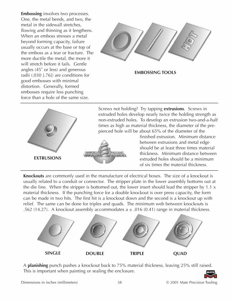
Embossing involves two processes.One, the metal bends, and two, themetal in the sidewall stretches,flowing and thinning as it lengthens.When an emboss stresses a metalbeyond forming capacity, failureusually occurs at the base or top ofthe emboss as a tear or fracture. Themore ductile the metal, the more itwill stretch before it fails. Gentleangles (45˚ or less) and generousradii (.030 [.76]) are conditions forgood embosses with minimaldistortion. Generally, formedembosses require less punchingforce than a hole of the same size.
Screws not holding? Try tapping extrusions. Screws inextruded holes develop nearly twice the holding strength asnon-extruded holes. To develop an extrusion two-and-a-halftimes as high as material thickness, the diameter of the pre-pierced hole will be about 65% of the diameter of the
finished extrusion. Minimum distancebetween extrusions and metal edgeshould be at least three times materialthickness. Minimum distance betweenextruded holes should be a minimumof six times the material thickness.
Knockouts are commonly used in the manufacture of electrical boxes. The size of a knockout isusually related to a conduit or connector. The stripper plate in the lower assembly bottoms out atthe die line. When the stripper is bottomed out, the lower insert should lead the stripper by 1.1 xmaterial thickness. If the punching force for a double knockout is over press capacity, the formcan be made in two hits. The first hit is a knockout down and the second is a knockout up withrelief. The same can be done for triples and quads. The minimum web between knockouts is.562 (14.27). A knockout assembly accommodates a ± .016 (0.41) range in material thickness.
A planishing punch pushes a knockout back to 75% material thickness, leaving 25% still raised.This is important when painting or sealing the enclosure.
Dimensions in inches (millimeters) 38 © 2001 Mate Precision Tooling
EMBOSSING TOOLS
EXTRUSIONS
SINGLE DOUBLE TRIPLE QUAD

The lower unit using an inverted punch normally performs the ‘lance’ part of a lance and formoperation. The ‘form’ takes place as the work piece is squeezed between the lower unit and aninverted die in the upper unit. A 5˚ minimum draft angle on the sides of the form improvesstripping and piece part quality.
The primary purpose for louvers is to permit the passage of air from one side of a panel to the other.A panel with louvers should be programmed to move through the press with the louver openingsaway from the direction of materialmovement. A .500 (12.70) radius isrecommended on the ends of a closed endlouver for stainless and cold rolled steelunder .060 (1.52) to prevent corners fromtearing. A 10˚ draft angle is standard on theends of an open end louver. To ensureflatness between louvers, a minimumspacing between the cutting edge of the firstlouver and the back edge of the secondlouver should be three material thicknesses.For spacing between rows (end to endspacing) a .314 (8.00) minimum isrecommended.
A shearbutton is a special purpose tool for placing locatingtabs in sheet metal for further fabrication such as shearingand spot welding.
Screw holding threads are pierced and formedin one operation with a thread form assembly.The domed shape with a screw thread actslike a locknut as a screw tightens it down.
© 2001 Mate Precision Tooling 39 Dimensions in inches (millimeters)
OPEN END CLOSED ENDOptions include straight or curved back styles, andcontinuous length louvers.
SHEARBUTTON TOOLS...Easy Shear Guides, Programmable
Lance and form assemblies can be any size and shape.
THREAD FORM

Mate Sheetmarker™Mate Sheetmarker™ Tool is used to "mark"or scribe the top surface of the sheet metal.The assembly uses a diamond point insert inan Ultraform® holder to create the etchings.The marking is the result of programscreated in the punch press programmingsystem. The Sheetmarker tool can be usedon all material types and thicknesses. Avariety of results can be produced, rangingfrom very light etching to fairly deepgrooves in the sheet. The press must becapable of holding the ram down while thesheet is moved on the x or y axis.
Mate Rollerball®
Mate Rollerball® assembly is used to make acontinuous bead emboss on a piece of sheetmetal. The Mate Rollerball is used in an autoindex station. The tool can make forms notpossible with single hit forming tools. TheMate Rollerball can form ribs, flanges oroffsets across the entire work surface. Thepress must be capable of holding the ramdown while the sheet is moved on the x or yaxis.
Dimensions in inches (millimeters) 40 © 2001 Mate Precision Tooling
for use in autoindex stations…

VII. Special Applications
A standard application is punching and nibbling within 80% of the press capacity. Standardmaterial thicknesses are mild steel and aluminum that are .020 to .157 (0.51 to 4.00) thick. 85%of the work done on turret presses falls into this category.
Special applications, are applications that are outside these parameters.
• Material less than .020 (0.51) thick• Material greater than .157 (4.00) thick• Special aluminum alloys• Stainless steel greater than .078 (2.00) thick• "Exotic" materials (inconel, hastalloy, plastics, etc.)• "Special" special shape• "Special" special assembly• Many hits and/or nibbling• Wall thicknesses of less than 2 1/2 material thickness• Special tolerances or hole cross-sections• Large holes (greater than 3.0 [76.20])• Small holes (less than 1 material thickness)• Tonnage greater than 80% of press capacity
Any one of the above existing conditions should be a warning to be alert to this particular job. Anytwo in combination will probably require special design and/or instructions.
Dimensions in inches (millimeters) 41 © 2001 Mate Precision Tooling

Special Applications
Punching Thick Material (over .157 [4.00])
• Use sharp punches and dies – sharpen when cutting edge has a .003 -.005 (.07-.13) radius –proper sharpening is critical
• Clearance of 25-30% of material thickness (reference die clearance chart)• Heavy duty back taper on punches• Minimum punch size (width or diameter) of .250 (6.35)• .020 (0.51) radius on all punch corners• Inspect tools frequently for wear• Lubricate the sheet, punch, guide• Run machine on slow cycle• Special care should be taken NOT to exceed press capacity (tonnage) when punching large
shapes – for best results, use 80% of press capacity• Bridge hitting is recommended – this will keep a balanced load on the punch• Nibbling is NOT recommended – if you must nibble, use 70% minimum of punch length –
DO NOT nibble with width of punch• ULTRA TEC® Heavy Duty Tooling is recommended
ULTRA TEC® Heavy Duty Tooling Advantages:
• 1˚ back taper (per side) on punches• Heavy duty Slug Free® die design• Heavy duty springs in ULTRA TEC® canister, 1 1/4" B station• Rooftop shear – B station and larger• Radius on all 90˚ corners to improve corner strength• Premium High Speed Steel (HSS) tool steel• Quick length adjust• Quick tool change• Maxima™ coating option
Punching Non-Metallic Material
• Use sharp punches and dies• Reduce die clearance by 5%-8%• Run the machine on slow cycle• Lubricate hard plastic if possible• Use Maxima™ coated punches• If marking occurs use urethane pads• Support thin material when possible
© 2001 Mate Precision Tooling 42 Dimensions in inches (millimeters)

Special Applications
Blanking Operations
Blanking is when the slug, normally the scrap part, becomes the saved or good part. The followingrecommendations will assist in making good quality blanks.
• Determine what blank dimensions are critical and inform Mate upon ordering that the tools are tobe used for blanking. When blanking, the die size is the blank size. Punch dimensions arecalculated from the die dimensions.
• Use only sharp punches and dies. This increases the straight or burnished portion of the blank toprovide straighter walls on the required parts.
• Reduce the die clearance by 5%. Reference die clearance chart in "The Perforation Process"chapter for proper clearance based on material type and thickness. This also helps increase theburnish area and minimizes the dimensional difference between the top and bottom of the blank.
• Punches should be flat-faced.
• Use straight taper dies.
• Inspect tools frequently for wear. We recommend more frequent inspection of the tools, sincetools will require sharpening more frequently when using reduced die clearances.
Dimensions in inches (millimeters) 43 © 2001 Mate Precision Tooling

Special Applications
Small Diameter or Narrow Holes
When punching small diameter or narrow holes, check that tools are properly sharpened andmaintained. The following recommendations are provided as guidelines to eliminate machine ortooling complications. In each situation, the user must consider their application, their machine,and their tooling before exceeding these recommendations.
Ratio of Punch to Material Thickness
This means that if the material being punched is .078 (2.00) thick aluminum, it is reasonable topunch a .060 (1.50) diameter hole with the above listed styles of tooling. If the material beingpunched is .078 (2.00) thick mild steel the smallest punch that is recommended is .078 (2.00)diameter (or wide shape). If the material being punched is .078 (2.00) stainless steel, the smallestpunch recommended is .157 (4.00) diameter (or wide shape).
This means that if the material being punched is .078 (2.00) aluminum, it is possible to punch a.039 (1.00) diameter hole using a Mate fully guided product. In mild steel that tool would need tobe a minimum of .060 (1.50), and in stainless a minimum of .078 (2.00) diameter (or wide shape).
© 2001 Mate Precision Tooling 44 Dimensions in inches (millimeters)
Mate ULTRA TEC® and Heavy Duty ULTRA TEC® Style Tooling:
Material Punch to Material Ratio
Aluminum .75 to 1
Mild Steel 1 to 1
Stainless Steel 2 to 1
Mate ULTRA TEC® Fully Guided Tooling:
Material Punch to Material Ratio
Aluminum .5 to 1
Mild Steel .75 to 1
Stainless Steel 1 to 1
Special Applications
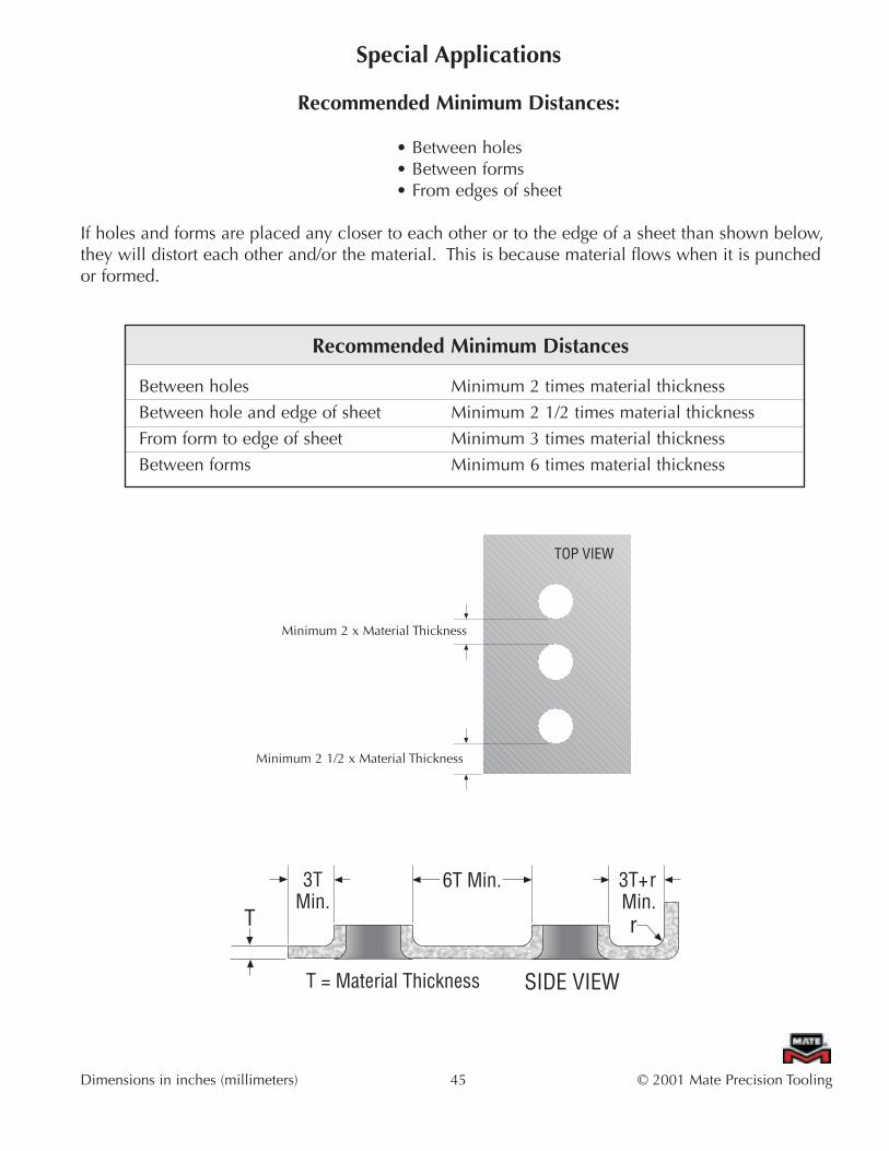
Recommended Minimum Distances:
• Between holes• Between forms• From edges of sheet
If holes and forms are placed any closer to each other or to the edge of a sheet than shown below,they will distort each other and/or the material. This is because material flows when it is punchedor formed.
Dimensions in inches (millimeters) 45 © 2001 Mate Precision Tooling
Recommended Minimum Distances
Between holes Minimum 2 times material thickness
Between hole and edge of sheet Minimum 2 1/2 times material thickness
From form to edge of sheet Minimum 3 times material thickness
Between forms Minimum 6 times material thickness
Minimum 2 x Material Thickness
Minimum 2 1/2 x Material Thickness
TOP VIEW
T = Material Thickness
T
3TMin.
6T Min. 3T+rMin.r
SIDE VIEW

VIII. Treatments and Coatings
Nitride Treatment
Nitriding is an optional heat treatment feature for high speed steel (HSS) punches. It is a surfacetreatment, which becomes an integral component of the structure of the material itself. Nitridedpunches are recommended for punching abrasive materials such as fiberglass or materials thatcause galling such as stainless steel, galvanized steel, or aluminum. It is also recommended forhigh speed nibbling applications. It is not recommended for punches smaller than .078 (2.00) indiameter or width, or for material thicker than .250 (6.35).
Maxima™ Coating
Maxima is a premium tool steel coating that has been specially formulated for turret punch presstooling applications. Maxima is a hard, wear resistant, multilayer Zirconium Titanium Nitride(ZrTiN) coating. It acts as a barrier between the punch and the sheet metal being punched andbecause of its exceptional lubricity, greatly improves stripping.
Maxima is applied to the precision ground surface of Mate’s premium high speed steel (HSS)punches. Since Maxima is an extremely hard, wear resistant, slippery material which reduces thefriction that occurs during the stripping portion of the punching cycle, it is particularly good forabrasive tooling applications. Less friction means less heat build up, less galling and longer toollife.
Dimensions in inches (millimeters) 46 © 2001 Mate Precision Tooling
ULTRA TEC® Tools That Can be Maxima coated:
Rounds .098 (2.50) and larger
Squares .098 (2.50) and larger
Rectangles and ovals .098 x .098 (2.50 x 2.50) and larger. However, if one side of the rectangle or oval is .250 (6.35) or greater, then the other side may be as little as .060 (1.50).
Cluster Insert All MT tooling sizes and all sizes of cluster inserts are acceptable.MT™ Punches

IX. Punch Shear
Punch "shear" is the geometry of the punch face. The standard shear for 1/2" A station through 3 1/2"D station ULTRA TEC® punches is flat – without shear. The standard shear for 4 1/2" E station is rooftopshear. Other shear types are available upon request. Shear helps reduce tonnage because the punchis not hitting with the full face on the material.
Advantages of Shear
• Tonnage reduction• Noise reduction• Slug control• Reduced shock loads• Improved stripping
Common Types of Shear
Rooftop shear is the best shear for minimizing tonnage in thicker materials.
Concave shear is a good alternative shear for nibbling. Without shear is recommended fornibbling.
One way shear is best for minimizing tonnage when blanking.
Four way shear is a good alternative shear used on square tools.
Dimensions in inches (millimeters) 47 © 2001 Mate Precision Tooling
Concave Rooftop
Four Way One Way

Punching Force Considerations
Punches with Shear - ConsiderationPunch shear tends to lessen punching force. The degree to which this happens is the SHEARFACTOR. Shear factor does change as the punch becomes less sharp. Note that the factory doesnot recommend using shear to bring punching force within press capacity, because dulling tooledges quickly raise punching force, and press capacity may be exceeded.
Material Thickness - Material thickness is the width of the workpiece or sheet that the punchmust penetrate in making a hole. Generally the thicker the material themore difficult it is to punch, but this isn't the only factor.
Material Shear Strength -Material shear strength is a measure of maximum internal stress before a given material begins toshear. This property is determined by metallurgical science and expressed as a numerical factor.Popular materials like aluminum, brass, mild steel and stainless steel have approximate shearstrengths of:
MATERIAL: SHEAR Strength-lbs/in2 (kN/mm2)Aluminum 5052 H32 25000 (0.1724)Brass 35000 (0.2413)Mild Steel 50000 (0.3447)Stainless 80000 (0.5516)
© 2001 Mate Precision Tooling 48 Dimensions in inches (millimeters)
MaterialThickness
PUNCHING FORCE CHANGES ASTOOLS BECOME DULL
HEAVY TOOL WEAR
Sharp DullTool Sharpness
Punc
hing
For
ceO
ptim
alEx
cess
ive
May exceedmachinetonnage
capability

Dimensions in inches (millimeters) 49 © 2001 Mate Precision Tooling
X. MaintenanceTo protect your tooling investment, knowing and practicing proper maintenance is essential.
Tools that are maintained and lubricated properly will produce quality holes and more piece partsat a lower cost per hole. See Mate’s full line ULTRA® Tooling Catalog for complete punch and diemaintenance instructions.
Torque RecommendationsPunches in ULTRA TEC® 2" C, 3 1/2" D, and 4 1/2" E punch guides should be tightened to 75 ft. lbs. (102 Nm).
Sharpening Rules• Sharpen frequently – in small amounts.
• Tools last longer if sharpened in small amounts --- .001-.002 (0.03-0.05) should be removed inone pass.
• Repeat until tool is sharp, normally .005 -.012 (0.13-0.30) total.
• Apply coolant with as much force and as close to the tool and wheel as is practical.
• Use the proper grinding wheel and dress the wheel often, using a rigid single or multi-pointdiamond.
• After sharpening, lightly stone the sharp cutting edges to remove any grinding burrs and to leave a.001 -.002 (0.03-0.05) radius.
• Provide proper face geometry.
• Observe proper set-up practices.
ESTABLISH WRITTEN MAINTENANCE PROCEDURES.
Benefits of Proper Tool Maintenance
• Improved Piece Part Quality• Flatter Sheets• Cleaner Holes• Longer Tool Life• Less Stress on Tools and Machine
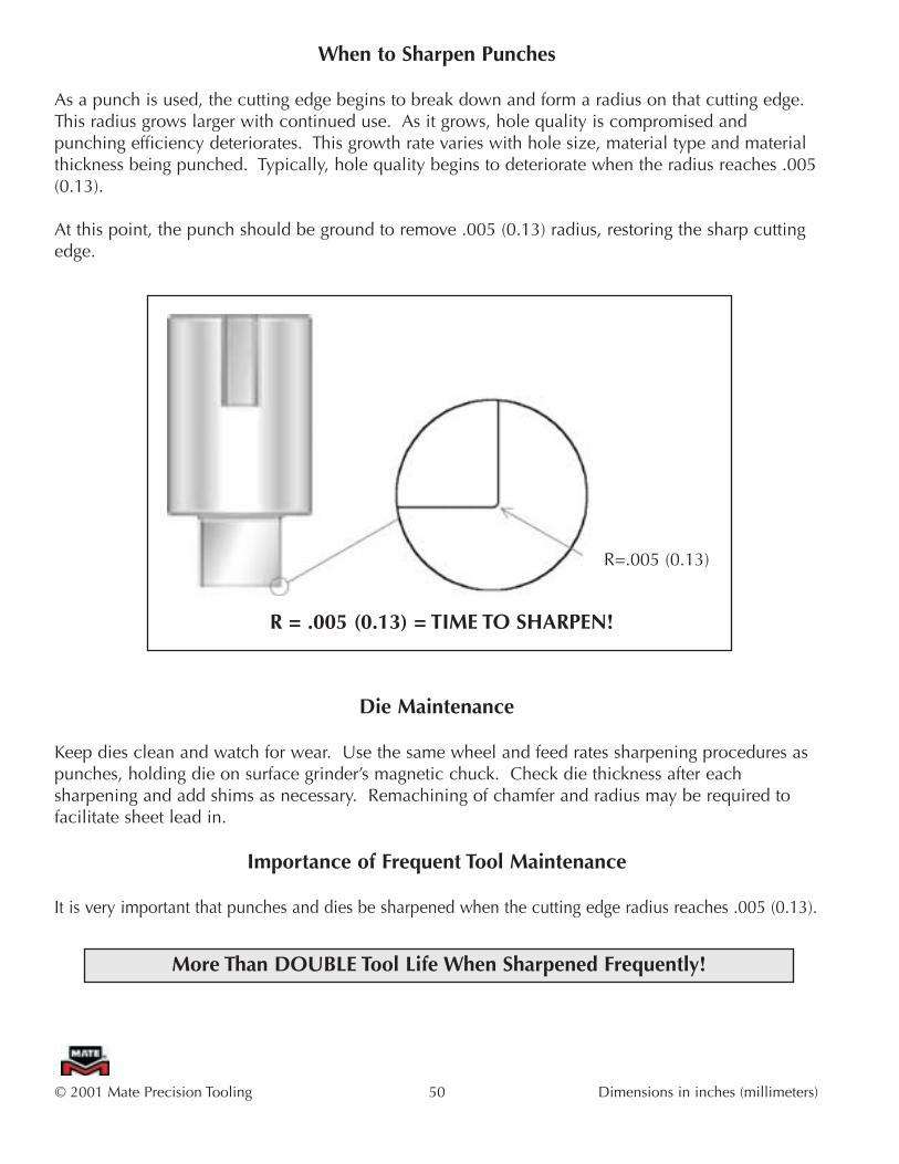
When to Sharpen Punches
As a punch is used, the cutting edge begins to break down and form a radius on that cutting edge.This radius grows larger with continued use. As it grows, hole quality is compromised andpunching efficiency deteriorates. This growth rate varies with hole size, material type and materialthickness being punched. Typically, hole quality begins to deteriorate when the radius reaches .005(0.13).
At this point, the punch should be ground to remove .005 (0.13) radius, restoring the sharp cuttingedge.
Die Maintenance
Keep dies clean and watch for wear. Use the same wheel and feed rates sharpening procedures aspunches, holding die on surface grinder’s magnetic chuck. Check die thickness after eachsharpening and add shims as necessary. Remachining of chamfer and radius may be required tofacilitate sheet lead in.
Importance of Frequent Tool Maintenance
It is very important that punches and dies be sharpened when the cutting edge radius reaches .005 (0.13).
© 2001 Mate Precision Tooling 50 Dimensions in inches (millimeters)
R = .005 (0.13) = TIME TO SHARPEN!
R=.005 (0.13)
More Than DOUBLE Tool Life When Sharpened Frequently!

Tool Maintenance Tips• Proper die clearance is critical.
• When punches get dull too fast, clearance may be too tight.
• Keep tools clean and watch for wear.
• Sharpen tools frequently – in small amounts.
• Always use coolant when sharpening.
• After sharpening, lightly stone the sharp cutting edges to remove any grinding burrs and to leave.001 -.002 (0.03-0.05) radius.
• Demagnetize the punch and spray on a light oil.
• Establish written maintenance procedures.
• Remove galling by rubbing with a fine stone parallel to the direction of the punching motion.
• If a piece-part is starting to show too much rollover, perhaps a tool is dull.
• If the punch press is making more noise than you think it should, perhaps a tool is dull.
• If the press is working harder than it used to, perhaps a tool is dull.
• Maintain press alignment.
• Check machine level and adjust if necessary.
• Examine punch and die holder for wear. Replace if necessary.
• Examine turret bores and die holder seats. Restore if they are damaged. Fix damaged keyways.
• Proper lubrication of tools extends tool life.
• Proper lubrication of sheet extends tool life.
• Use of Maxima™ increases tool life.
• Use Slug Free® dies.
• Recommended die penetration is .118 (3.00).
Dimensions in inches (millimeters) 51 © 2001 Mate Precision Tooling

Factors Affecting Tool Wear
Hole Size – Small punches will wear faster than larger punches.
Hole Configuration – Sharp corners will show wear much more quickly than straight or curvededges, particularly on punches. Narrow sections will wear faster than heavier sections.
Shear Face on Punch – The portion of the punch that strikes first does most of the work and will,therefore, wear faster.
Clearance – Proper clearance will yield longer tool life.
Punching Conditions – Reducing the hitting shock and holding the sheet flat allows the punch tocut cleanly and will give better life to the punch.
Stripping Conditions – Stripping the work piece from the punch evenly contributes to easystripping.
Turret Alignment – Mechanical damage of punches and dies is often misinterpreted as wear. Tightclearance on one side of a punch and die will accelerate wear at that point. It is critical toregularly check turret alignment in order to prevent problems such as unacceptable part quality andturret wear.
Tool Material – To develop toughness and hardness required for long life, high speed steel (HSS)undergoes several heat treatments. The punches are double tempered to C 62 Rockwell hardness.Hardened (59 Rockwell C) tool steel is the optimum material for dies. It correctly balances theneed for maximum edge wear without breakage.
Punching Speed – High punching speeds can, under certain conditions, generate enough frictionalheat to soften a punch. A softer punch will wear much faster.
Lubrication – A lubricant will increase tool life significantly.
Work Piece Thickness – Thicker material will cause faster punch wear.
Work Piece Properties – Physical and mechanical properties of the work piece will greatly affecttool life.
Punch/Die Wear – Punches will generally wear faster than dies. Dies are less affected by thefactors described above than punches.
© 2001 Mate Precision Tooling 52 Dimensions in inches (millimeters)

Maintenance
Minimum Punch Lengths
Original Thick Turret Punch in ULTRA TEC® Guide Assembly
ULTRA TEC® Punch in ULTRA TEC® Guide Assembly
Minimum Die Height
Die height of stations 1/2" A through 4 1/2" E is 1.187 (30.15).
.125 (3.18) Grind Life. Dies may be sharpened 10 to 20 times at .005 -.010 (0.13-0.25) persharpening. After sharpening, remachining of chamfer and radius may be required to maintainsheet lead in.
Dimensions in inches (millimeters) 53 © 2001 Mate Precision Tooling
Minimum Punch Lengths
A 4.246(107.85) .742(18.85) .020(0.51) .118(3.00) .157(4.00) .447(11.35) 3.799(96.50)
B 3.957(100.50) .742(18.85) .020(0.51) .118(3.00) .157(4.00) .447(11.35) 3.510(89.15)
C 3.786(96.16) 1.004(25.50) .020(0.51) .131(3.33) .315(8.00) .538(13.67) 3.248(82.49)
D 3.313(84.15) 1.004(25.50) .020(0.51) .163(4.14) .315(8.00) .506(12.86) 2.807(71.29)
E 3.353(85.17) 1.043(26.50) .020(0.51) .204(5.18) .315(8.00) .505(12.82) 2.848(72.35)
Station Straight BeforeRadius (SBR) Penetration
StripperLand
MaximumGrind Life
MinimumPunch Length
PunchOverall Length
MaterialThickness
Minimum Punch Lengths
A 8.169(207.50) .664(16.87) .020(0.51) .118(3.00) .157(4.00) .369(9.37) 7.800(198.13)
B 8.169(207.50) .742(18.85) .020(0.51) .118(3.00) .157(4.00) .447(11.35) 7.722(193.15)
C 3.786(96.16) 1.004(25.50) .020(0.51) .131(3.33) .315(8.00) .538(13.67) 3.248(82.49)
D 3.313(84.15) 1.004(25.50) .020(0.51) .163(4.14) .315(8.00) .506(12.86) 2.807(71.29)
E 3.353(85.17) 1.043(26.50) .020(0.51) .204(5.18) .315(8.00) .505(12.82) 2.848(72.35)
Station Straight BeforeRadius (SBR) Penetration
StripperLand
MaximumGrind Life
MinimumPunch Length
PunchOverall Length
MaterialThickness
The maximum die sharpening of thick turret Slug Free® dies is .125 (3.18)

Dimensions in inches (millimeters) 54 © 2001 Mate Precision Tooling
TroubleshootingProblem Possible Cause Solution Suggested
Incorrect die clearance • Adjust to properDiffering material hardness • Adjust clearancealthough gage is the sameDull punches and dies • Sharpen toolingSlug pileup or packing • Check dies and clear
• Increase punch penetrationHolder or station misaligned • Check alignmentDull punches and dies • Sharpen toolingImproper clearance • Adjust to properDie not properly seating • Check diesHolder or station out of alignment • Check alignmentPunching thin material • Use guided toolingInadequate die clearance • Adjust to properCrossed shapes • Ensure tools are properly
loaded in turretSize of punch less than one • Use guided toolingmaterial thicknessDull punches or dies • Sharpen toolingImproper die clearance • Adjust to properDifficult material • Adjust die clearanceWeak spring • ReplaceTool limitations exceededGalling • Lubricate tooling
• Maxima™ coatingDull Punch • Keep tools sharpNo lubrication • Lubricate the work pieceHit rate • AdjustCoating • Maxima™ coating
recommendedInadequate die clearance • Increase die clearanceDull punch and/or die • Sharpen toolsInadequate die clearance • Increase die clearanceGalling on punch • Remove galling/Maxima™
coating recommendedInadequate lubrication • Lubricate work pieceWeak Spring • Increase stripping
XI. Troubleshooting
Excessive Burrs
Poor Hole Quality
Punch Breakage
Punch Does Not Strip
Punch Galling
Punch Sticking inWork Piece

© 2001 Mate Precision Tooling 55 Dimensions in inches (millimeters)
TroubleshootingProblem Possible Cause Solution Suggested
Inadequate die clearance • Increase die clearancePunch overheating • Lubricate toolsPoor sharpening practices • See maintenance sectionNibbling • Alter programmingPoor stripping • Maxima™ coating
recommendedPoor tool alignment • Realign stations
• Level turret• Replace tool holders
Material being punched • Maxima™ coating(for example, stainless) recommendedWorn work holders • Adjust or replace
• Replace gripping surfacesAlignment problems • Realign table to press
• Inspect for worn turret bores
• Level turretMagnetism in tools • DemagnetizeSmall diameter holes** • See below**
Tool improperly ground • Dress wheel and grind taking light cuts
Dull tools • Sharpen punch and dieImproper clearance • Increase or decrease as
necessaryNo lubrication • Lubricate sheetPoor stripping • Increase strippingProgramming • Reprogram punching
sequence• Bridge hit large openings• Radius and polish die top• Shim dies evenly• Self-adhesive urethane
stripper pads
Rapid Tool Wear
Sheet Accuracy
Slug Pulling
Warpage of Work Piece
Work Piece Marking
Surface Cracks onFace of Punch
**The most common condition(s) for slug pulling are: round holes .250to .750 (6.35 to 19.05) diameter in .039 to .078 (1.00 to 2.00) thickmaterial, with sharp tools, using optimum clearance, and minimumpenetration on oiled material. The solutions suggested are to:
• Maximize die penetration• Use Mate Slug Free® dies

XII. Tips and Techniques
The Do’s and Don’ts of PunchingDO
1.Keep tooling sharp.2. Use proper die clearance.3. Clean tooling on a regular schedule and use lubrication when possible.4. Order dies by punch size + clearance (for uniform corner clearance).5. Sharpen punches and dies correctly at proper time – edge breakdown of .005 -.010 (0.13-
0.25), .001 -.002 (0.03-0.05) per grinding wheel pass.6. Program correctly – bridge hit, use 75% of parting tool, nibble 2.5 material thickness’, cut large
cut-outs along the same axis.7. Recommendation: Holes be a minimum of 2 1/2 times material thickness from the edge of
sheet being punched.8. Check turret bores.9. Check punch and die holders for wear.
10. Clean and inspect press components.11. Check and level press.12. When nibbling large holes use 2 tools of the same size. Tool change frequently between them
to avoid overheating.
DON’T1. "Nibble" when you can "punch".2. Have unnecessary punch shear.3. Use tool with an offset centerline.4. Re-enter a punched hole (using a cluster assembly to complete pattern).
Dimensions in inches (millimeters) 56 © 2001 Mate Precision Tooling

I/O Radius Tool cuts both inside and outside radiiSmall, precise tabs keep slugs and blanks intact whilebeing punched, yet permit them to break away fromeach other easily off the machine. The recommendedwidth for the tab is .015 (0.38) gap between hits. Thetool is for use in an auto index station. Inside radiusmust be larger than outside radius. Programmingrequirements are included with the tooling.
Placing the form on the sheet with the grain running perpendicular to the formcan reduce tearing or splitting of over stressed metal forms. Corners of highlouvers, high extrusions, complex lance and forms, and card guides aretypically vulnerable to this effect. Liberal application of a forming lubricant isalso recommended to let the metal slide more freely over the forming surfaceof the tool, especially in stainless steel.
Parts to be welded can be positioned precisely, when shearbuttons areprogrammed into surfaces to be joined. Layers of material come togetherwith NC accuracy.
Costs for bolts and lockwashers can be eliminated, if thread forms canbe programmed into a part. This domed shape with a screw thread actslike a lock nut as a screw tightens it down. Mate’s special thread formtools make both the screw hole and the raised dome in one hit.
Inscribe parts on a punch press to reduce costly separate operations.Inscribing numbers, words, or any combination thereof can be programmedinto your punch press with Mate stamping tools. Produce one or two lineswith one hit. The characters line up straight and depth of impression isuniform.
Mate Sheetmarker™ tool can be used to inscribe or mark sheetmetal.Mate Sheetmarker™ assembly is available for presses that can hold the ram down while the sheet is allowed to move.
If stainless steel extrusions are distorted, apply a good forming lubricant tothe material before making the extrusion. Not only will the material releasefrom the die better, it slides over the die surface smoothly when being formed.This gives the material a better opportunity to distribute the forces of bendingand stretching, preventing distortion in the formed wall and tearing at the base of the extrusion.
© 2001 Mate Precision Tooling 57 Dimensions in inches (millimeters)
Insideradius
Outsideradius
NO. 368NO. 368
Gra
in

Galling is an adhesion to the punch tip by the metal beingpunched, caused by pressure and heat. The best techniquefor removing galling is to rub it off with a fine stone. Therubbing should be done parallel to the direction of thepunching motion. This will polish the surface that contactsthe material, decreasing any chance of future galling. Donot sandblast, belt sand or use other harsh abrasive methods.These create a coarse surface finish to which materialadheres more easily.
Shake-and-break is a popular name for this easy method of separating multiple parts from a sheetof material. The method is based on small, interconnecting tabs between the parts created byprogramming spacing of the shearing or slitting punch. These tabs keep the sheet and parts intactwhile being punched, yet are easy to separate off the machine. The tabs should be .008 (0.20)wide. Straight, curved, or corner shaped tools are available.
Combating material warp.If you are punching a large number of holes in asheet and the sheet does not stay flat, it could becaused by the cumulative effect of punching.Each time a hole is punched, materialsurrounding the hole is stretched downward,placing the top of the sheet in tension. Thedownward movement causes a correspondingcompression at the bottom of the sheet. Oneway to counteract this effect is to punch everyother hole first and then come back and punchthe remaining holes. This places the sameamount of force on the sheet, but it disruptstension/compression accumulation that occurswhen punching operations follow one another inclose succession and in the same direction.
Use Mate’s urethane stripper pads to punch painted surfaceswithout marring. These self-stick pads can be applied to ULTRATEC® stripper faces. Pads are available for all stations A through E.
Dimensions in inches (millimeters) 58 © 2001 Mate Precision Tooling
STRAIGHTCURVED
CORNERS
1 1 1 1 1
1 1 1 1 1
1 1 1 1 1
1 1 1 1 1
2 2 2 2 2
2 2 2 2 2
2 2 2 2 2
2 2 2 2 2

Notch a variety of angles with one set of 3-way corner notching tools. This is anotherapplication for an auto index station. A 3-waycorner notching tool can cut any angle largerthan the smallest point by programming singleor multiple hits. 15˚ is the smallest angleavailable.
Clearance corners in dies control corner burrs. A radius in thecorners of rectangular and square dies with clearance greater than.020 (0.51) keeps clearance uniform around the corner of the punch.If the die is sharp cornered too, then distance between punch and diecorners would be greater than side clearance, resulting in large burrs.
Mate Rollerball® assembly is used to make a continuous bead emboss on a pieceof sheetmetal. The Mate Rollerball® is also capable of offset forming. Theassembly is available for presses that can hold the ram down while the sheet isallowed to move.
Shaving makes straight-walled holes without drilling.When you need a smooth, straight-walled hole, shaving can save the time and trouble ofperforming a second operation on another machine. To do this, you need to punch the hole twice.First use a punch with total clearance taken off equal to 20% of material thickness, and a die withtotal clearance .004 (0.10) over the desired finished shaved hole size. Then, program a second hitin the same place using the same size die, and a punch the size of the desired finished hole. Thesecond operation will shave the sides of the hole, removing most of the rollover and fracture effectscaused in the first step, andenlarge the burnished area.This operation works best onmild steel and other materialsthat shear well. The exampleshown is a finished shaved holeof 1.000 (25.40) diameter in.187 (4.75) thick material.
Form down last. When using forming tools, formdown operations are generally avoided becausethey take up so much vertical room and anyadditional operations tend to flatten them out orbend the sheet. They can also drop into dies, get
caught and pull out of work holders. However, if a form down operation is the only solution for aparticular piece part, make it the last operation on the sheet.
© 2001 Mate Precision Tooling 59 Dimensions in inches (millimeters)
DIEUNIFORM
CLEARANCEPUNCH
MATERIAL
1.004(25.50)DIE DIAMETER
.967(24.56)PUNCH
DIAMETER
DIE
FIRSTHIT
SECONDHIT
1.000(25.40)PUNCH
DIAMETER
.187(4.75)MATERIAL THICKNESS
MATERIAL
DIE1.004(25.50)
DIE DIAMETER
1st hit2nd hit
98°
59°
77° 77°
59°
TWO POPULAR CONFIGURATIONS…
75°
45°
60°
90° 60°
30°
FORMLAST

Bridge hitting reduces tool wear.By alternating hits when performingshearing/slitting operations, forces uponthe tool remain balanced from side toside and end to end. As a result, thepunch operates square to the materialand die. Over the long run, this willreduce the frequency of sharpening andgenerally longer tool service. Thispractice is called "bridge" hitting becausethe full hits leave a "bridge" of materialbetween them that is removed by thenext sequence of hits.
If punches overheat:• Use a lubricant. This will decrease friction.• Use more than one punch of the same size in the sequence. By alternating the punches, there
will be a longer time for each punch to cool down before it is used again.• Simply give the tool a rest. Program tool changes to interrupt long repeated operations.• Slow the press down.• Use Maxima™ coating.
What do your slugs tell you?The slug is essentially a mirror image of the hole,with the same parts in reverse order. By examiningyour slugs you can tell if punch-to-die clearance iscorrect. If clearance is too large, the slug willshow a rough fracture plane and a small burnishzone. The larger the clearance, the greater theangle between the fracture plane and the burnishzone. If clearance is too small, the slug will show a fracture plane with little angle, and a largeburnish zone. An ideal slug is created when the fracture planes coming from the top and thebottom of the material have the same angle and form in alignment with each other. This keepspunching force to a minimum and forms a clean hole with little burr. At this point, any extensionin tool life gained by increasing clearance comes at the sacrifice of hole quality.
Dimensions in inches (millimeters) 60 © 2001 Mate Precision Tooling
ALTERNATE BRIDGE HITTING BALANCES FORCES ( )
FULL HITS FULL HITS FULL HITS
BRIDGE HITS BRIDGE HITS BRIDGE HITS
CONSECUTIVE NIBBLING UNBALANCES FORCES ( )
ABC
D
AB
C
D
HOLE/SLUGGEOMETRYA. RolloverB. BurnishC. FractureD. Burr
SLUG
MATERIAL
Proper clearance
Fracturelines meet
Fracture linesdo not meet
Clearance too tight Clearance too large

Recommended minimum distance between holes, between forms and from edges of sheets. If holesand forms are placed any closer to each other or to edges of sheets than is given below, they maydistort each other or the material.• Minimum 2 times material thickness between holes.• Minimum 2 1/2 times material thickness between hole and edge of sheet.• Minimum 3 times material thickness from form to edge of sheet.• Minimum 6 times material thickness between forms.
Recommended die penetration is .118 (3.00).
How to punch large holes without exceeding press tonnage.Although tooling is available for round holes up to station maximums for the largest station, suchholes can exceed press capacities, especially in high shear strength materials. Creating the hole withmore than one hit may solve the problem. Using smaller tools to break long perimeters on large tools
can cut tonnage by a half or more, withoutresorting to nibbling the entire periphery. Thediagrams use rounds, double D’s, a quad radiusand a biconvex radius. In all three, slugs fallaway through the die, leaving no scrap on thepunch press table.
Start continuous louvers in the center.Continuous louver tools are now designed to produce smooth-edged, level-topped louvers when recommended procedures arefollowed. Start in the center and form to one side and then theother in .030 (0.80) increments. If needed, complete the processby rehitting the center for ultimate flatness.
© 2001 Mate Precision Tooling 61 Dimensions in inches (millimeters)
Minimum 2 x Material Thickness
Minimum 2 1/2 x Material Thickness
TOP VIEW
651-481-6 7
A. Shape and hit B. Shape and hit C. Shape and hit
1&2 3
1
3
2
5
6
478 8 1 231
4
2
3
56
6
BEGIN AT CENTER
WORK TO SIDE IN .030(0.8) INCREMENTS
RETURN TO CENTER AND WORK OTHER SIDE
RETURN FOR CENTER HIT IF NECESSARY

XIII. GlossaryA2 Tool Steel. A2 tool steel has a higher toughness/hardness ratio, with minimum movement inhardening and a greater wear resistance than oil hardened tool steels.
Actual Size. The measured size of the die with the total clearance included.
Alpha Numeric Stamping Assembly. A special assembly that stamps letters or numbers into sheetmetal using replaceable character inserts.
Beading Tool. An embossing assembly that can hit continuously along the sheet to form a long,strengthening rib.
Blank. Any part cut from a sheet of metal that is not scrap.
Blanking. When saving the slug as the finished product. The punch is made without shear. The diesize determines the blank size.
Bridge Hitting. Programming a wide section of material between each hit during the first punchingsequence and then removing that entire section (or bridge) during another sequence of hits.
Burnished Land. The shiny, sheared portion of the hole in the sheet metal in between the rolloverand the burr.
Burr. The rough edge that protrudes out of the bottom side of the sheet after punching.
Burr Height. The visible part of the burr hanging below the sheet. With optimum clearance, theburr height is approximately 10% of the material thickness.
Cable Opening. A special shape (see E6 in "Special Shapes" chapter).
Cantilever. A projected area in a special shape die that is likely to break. A keyway is a goodexample.
Card Guide. A special assembly tool that forms the material up into a channel.
Cartesian Coordinates. This angle setting method sets 0 degrees at 3 o'clock, and the followingangle settings are set counterclockwise from there. The system is named for the French philosopherand scientist René Descartes.
Centerline Drawing. A drawing furnished for all special shape punches and dies used forprogramming and reordering.
Dimensions in inches (millimeters) 62 © 2001 Mate Precision Tooling

Centerpoint. A special assembly that puts cone-shaped indentations, used for locating, into thesheet.
Cluster. A special assembly that produces multiple holes in one hit.
Concave shear. The concave shear arches into the center of the punch face, with the center strikingthe metal last.
Convex or "Rooftop" Shear. This punch face angles to a point, with the center of the punch strikingthe metal first. This shear should not be used in any notching operations because it will push thepunch away from the cutting operation which may result in an unsatisfactory hole.
Countersink (Universal). A tool used to form a taper in a prepierced hole to accept a flatheadscrew or rivet. The depth of form may not exceed 60% of material thickness.
Dedicated Countersink. This tool is similar to a universal countersink, except it is used specificallyfor one material thickness and one screw size, and the depth is up to 85% of the material thickness.It is used with a blank die.
Deviation Clause (DC). Indicates that the tool deviates from or exceeds the press manufacturer’sstandards or recommendations. Tools ordered with this clause are not guaranteed.
Die. A tool that supports the sheet metal as the punch penetrates through it. The die hole must belarger than the punch. The die size is determined by the thickness and type of material beingpunched.
Die Clearance. The difference in size between the punch dimensions and the die dimensionswhich allows for the proper shearing of the material being punched. Based on the thickness andtype of material being punched.
Die Holder. Holds the die into the lower turret.
Die Land. The usable cutting edge of the top surface of the die.
Die Line. The plane at which the top of all standard dies sit, when properly installed.
Die Pin. A pin in the die for locating in the die holder.
Double D. A special shape (see A2 in "Special Shapes" chapter).
Double Keyhole. A special shape (see F1 in "Special Shapes" chapter).
Double Keyway. A special shape (see D5 in "Special Shapes" chapter).
Ellipse. A special shape (see E10 in "Special Shapes" chapter).
© 2001 Mate Precision Tooling 63 Dimensions in inches (millimeters)

Emboss. A special assembly that forms without cutting, producing raised or sunken designs in sheetmetal.
Engraved Punch. A punch, used with a blank die, to stamp characters .005 -.008 (0.13-0.20) deepin sheet metal. Some examples are numbers, letters, and logos.
Equilateral Triangle. A special shape (see C1 in "Special Shapes" chapter).
Etch. The engraving of a number, letter, or combination thereof, on a tool used for identificationpurposes. Etch numbers are always assigned to special shapes and special assemblies.
Extrusion. The forming of material upward, usually in a round shape. It is normally prepierced,then formed. Usually designed to accept self tapping screws.
Feed Gap (Turret Gap). The distance between the upper turret and the top of the lower die.
Forming. An operation that shapes the material.
Four-way Corner. A special shape punch and die used for rounding corners of parts (see E1, E2, E3in "Special Shapes" chapter).
Four Way Shear. A shear ground in four different quadrants that meet in the center.
Fully Guided. Guiding at punch point supports punch. Accurate and close tolerances betweenguide and stripper hold punch rigid. Increases hole accuracy, improves stripping, controls againsthole distortion and saw toothing.
Galling. Metal depositing on the sides of the punch point.
Gage. A system of measurement for the thickness of sheet metal.
Grind Life. The maximum useable length that can be removed from a punch or die by sharpening.
HSS. High Speed Steel. A tool steel used for making punches and punch inserts. The hardness is60-62 Rockwell C scale.
Hardening. Any process of increasing hardness of metal by suitable treatment, usually involvingheating and cooling.
Heavy Duty. Style of tooling designed for thick material applications .157 (4.00) and over.
Hinge Tools, 1 and 2. A pair of special assemblies that form hinge knuckles directly on the edge ofthe part. Hinge tool 1 lifts the tab tips and orients the tab centers. Hinge tool 2 rolls the tabs allthe way over. Inserting a hinge pin joins the hinged parts together.
Dimensions in inches (millimeters) 64 © 2001 Mate Precision Tooling

Indexing. Any time you rotate a punch and die to an angle within a 360 degree range.
Inside/Outside Radius Tool. A tool designed for use in auto indexing stations that cuts both insideand outside radii without stopping the machine to remove the slug or blank.
Internal Key. A key attached to the inside of a guide that locates the punch in the guide.
Jumper. A tool ordered out of station range.
Key. A device used to locate or align something. One example is a key to position tooling in aholder, or the holder in a turret.
Keyhole. A special shape (see D1-D4 in "Special Shapes" chapter).
Keyway. A special shape (see C5, C6 in "Special Shapes" chapter).
Knockout. The process of cutting and forming material, except the slug is held into the sheet metalby a tab or tabs.
Lance and Form. A tool that slits and forms an opening in a part in just one hit.
Line-up Tools. Tools used to align the upper turret with the lower turret.
Louver. A special assembly tool that forms the material up for an air opening. It cuts and forms thematerial in one hit.
Lubricant. A substance capable of reducing friction, heat, and wear during punching and formingoperations when introduced as a film between solid surfaces.
Maxima™ Coating. A premium tool steel coating. Maxima is a hard, wear resistant, multilayerZirconium Titanium Nitride (ZrTiN) coating (see "Treatments and Coatings" chapter).
Maximum Tonnage. The rated force that a press is designed to exert at a predetermined distanceabove the bottom of the stroke of the slide.
Multi-Tool. An assembly that holds more than one punch. A "turret within a turret".
Nibbling. Nibbling is a process where the sheet advance is less than the size of the punch beingused to make a hole. Doing this in a series causes an elongated hole to be created. Commonlyused with round punches to create an oval opening or circular cut out.
Nine-Way Corner Rounding. A special shape tool that provides nine external radii.
Nitride Treatment. A gas heat-treating process used to produce a hard, wear-resistant case onsteels. It can be used advantageously only on tool steels that do not temper back excessively at thenitriding temperature, 975˚ C (see "Treatments and Coatings" chapter).
© 2001 Mate Precision Tooling 65 Dimensions in inches (millimeters)

Notching. To cut or make an indentation in something. This involves removing the material fromthe corner of the sheet, often at an angle, to allow bending.
Octagon. A special shape (see B5 in "Special Shapes" chapter).
Off-Center Punching. When the entire periphery of the punch is not engaged with the materialbeing punched.
Oil Canning. Warpage or bending caused by punching or forming the sheet metal.
One way Shear. A one way sloped shear that angles to a longer point on one side of the punch.
Parting. An operation usually performed to produce two or more parts from one commonstamping.
Perforating. The process of punching a number of uniformly spaced holes in a piece of metal. Theholes may be any shape, and they usually cover a large portion of the entire sheet.
Pierce After Emboss. A punch and die used to pierce a hole into a piece of formed sheet metal.
Pierce and Emboss. A special assembly that pierces and forms sheet metal in one hit.
Pierce and Extrude. A special assembly that pierces and extrudes sheet metal in one hit.
Piercing. The general term for cutting, shearing or punching openings, such as holes and slots insheet material, plate, or parts.
Planishing. A flat punch used with a blank die to push a knockout back into the sheet (75%maximum).
Punch. A tool used to pierce through sheet metal.
Punch Tip. The point of the punch that actually pierces through the sheet metal.
Punching. The process of using a punch and die to pierce a hole or opening, or to form a shape, orstamp a surface.
Quad Radius. A special shape with a different radius on each of the four sides designed to nibblelarge holes with smoother edges in fewer hits than a round nibbling punch.
Radius Corner. A corner on a punch and die that has been rounded.
Rect/Oval. A special shape with sharp 90˚ corners on one end and a full radius on the other end(see B3 in "Special Shapes" chapter).
Relief. Clearance obtained by removing metal, either behind or beyond the cutting edge of apunch or die.
Dimensions in inches (millimeters) 66 © 2001 Mate Precision Tooling

Roller Ball Die. Die used in stations adjacent to forming stations. It is a solid die with a springloaded ball bearing installed which supports the work piece and allows it to clear the feed gap foreasy travel.
Rollerball®. Mate Rollerball assembly is a forming assembly used to make a continuous beademboss on a piece of sheet metal. The press must be capable of holding the ram down while thesheet is moved on the x or y axis.
Rollover. The top part of the sheet that is drawn and formed into the hole being punched.
Rooftop Shear. See "convex" shear.
S7 Shock Steel. A more shock-resistant steel than the A2 steel, that dies are made from. This steelcontains less carbon and has increased toughness. It is employed where heavy cutting or formingoperations are required and where breakage is a problem.
ScissorTool™ Assembly. A shearing assembly used for parting, slitting and sheet squaring. TheScissorTool™ Assembly is designed for use in auto indexing stations which permit programmedcutting at any angle.
Set-Up Instructions. A set of instructions included with all special assemblies, used to assist insetting up tools.
Shake-and-Break. A special shape piercing tool that leaves retaining tabs in between parts for easyseparation of multiple hit parts.
Shank. The main body of the tool.
Shape. The physical appearance; any shape other than round.
Shear. The geometry of the punch face, other than flat. It helps reduce tonnage because it is nothitting with the full face of the punch.
Sheetmarker™. Mate Sheetmarker assembly uses a diamond point insert to scribe or "mark" thetop of the piece of sheet metal. The press must be capable of holding the ram down while thesheet is moved on the x or y axis.
Shim. A thin piece of metal used to fill in space between items.
Single D. A special shape (see A1 in "Special Shapes" chapter).
Slug. The pieces of material (usually scrap) which are produced when punching holes in sheetmetal.
Slug Free®. Refers to dies, which have an hourglass taper to prevent slugs from pulling back upwith the punch. Slug Free® is a registered trademark of Mate Precision Tooling.
© 2001 Mate Precision Tooling 67 Dimensions in inches (millimeters)

Slug Shedder. Small urethane in the shape of a cylinder used to aid stripping of the slug away fromthe punch. The two sizes for thick turret tooling are .118 (3.00) and .236 (6.00) diameter.
Slug Shedder Hole. A hole in the face of the punch for urethane slug shedders to be inserted.
Special Assembly. A special punch and die tool assembly that will shape and/or form the material.
Special Shape. A shape other than a round, square, oval, rectangle, single D or double D.
Station. A position in the turret of variable sizes for various punch and die ranges.
Stripper Plate. A metal plate designed to surround the punch. Its purpose is to strip the sheetmetal from the face of the punch.
Stripping. The process of removing the punch from the sheet metal.
Thread Forming Assembly. An assembly that pierces and forms an inverted thread configurationthat will accept a wide variety of sheet metal screws with various thread sizes. The dome shapeacts as a spring lock washer when the screw is tightened providing extra strength. The assemblywill pierce a through-hole and form the dome in one hit.
Three-way Notching Tool. A triangle shaped punch and die for use in creating a variety of anglednotches. Two popular configurations are 30˚-60˚-90˚ and 45˚-60˚-75˚.
Tonnage. The measurable force needed for punching or forming sheet metal.
Torque. A measurement of a twisting force. For example, a measurement of how much to tighten ascrew.
Total Clearance (TC). The size difference between the punch and the die that allows the punch tofit through the die and make a clean break in the sheet metal.
Triangle. A special shape (see C1-C4 in "Special Shapes" chapter).
Turret. A pivoted and revolvable holder in a machine. The name is derived from the manner inwhich tools are mounted in the press. An upper turret holds the punch holders (punches), and alower turret holds the respective die holders (dies).
Two-way Corner. This special shape is a four-way corner cut in half.
ULTRA TEC®. ULTRA TEC® is a premium tooling system for thick turret style machines (see "ULTRATEC® Tooling System" chapter).
ULTRA ABS®. ULTRA ABS is a premium tooling system for use only in Amada brand thick turretmachines configured with ABS. Ultra ABS is licensed by Amada Inc.
Dimensions in inches (millimeters) 68 © 2001 Mate Precision Tooling

Without Shear. When the punch face is completely flat. The entire face of the punch has contactwith the material being cut. This is used for blanking, as it does not distort the slug (blank).
Work Piece. Any material part or piece that is being processed or handled to or from a processingoperation.
Mate Precision Tooling1295 Lund Boulevard
Anoka, Minnesota 55303 USAPhone 800-328-4492 • 763-421-0230
Fax 800-541-0285 • 763-421-0285mate.com
email: [email protected]
The Mate Logo, ULTRA, ULTRA TEC, ULTRAFORM, Rollerball and Slug Freeare registered trademarks of Mate Precision Tooling Inc.
MT, Sheetmarker, Maxima, and ScissorTool are trademarks of Mate Precision Tooling Inc.
© 2001 Mate Precision Tooling 69 Dimensions in inches (millimeters)
LIT00068Rev A