Embed Size (px)
Citation preview
WEL-DINCS RCSEARCH SUPPLEMENT TO THE WELDING JOURNAL, NOVEMBER 1976
Sponsored by the American Welding Society and the Welding Research Council
Material Variables Affecting Lamellar Tearing Susceptibility in Steels
Detailed investigation shows the tendency to lamellar tearing is too complex a phenomenon to fit the more commonly accepted susceptibility criteria
BY S. GANESH AND R. D. STOUT
ABSTRACT. A quantitative weldabi lity test was employed to determine the lamellar tearing susceptibil ity of steels with a variety of melting and deoxidation practices, composit ions and thicknesses. The degree was examined to which susceptibil ity was related to inclusion type and dist r ibu t ion , oxygen content , m ic ro-st ructura l features, and f rac ture mechanisms. While tearing was generally associated with the elongated nonmetall ic inclusions, in some steels initiation occurred by splitt ing along ferrite bands, l iquation or intergranular cracking. Susceptibil ity was observed to increase with an increase in the oxygen content of the steel, but the inclusion count obtained using the Quantimet 360 did not show a satisfactory correlation. Voids formed either by decoherence or cracking of inclusions, and terrace l inkage of adjacent voids occurred by several modes such as necking, microvoid
S. GANESH is with the Bendix Research Laboratories, Southfield, Michigan, and Ft. D. STOUT is Dean, Graduate School, Lehigh University, Bethlehem, Pennsylvania.
The work was sponsored by the Welding Research Council and was presented at the 57th AWS Annual Meeting held at St. Louis, Missouri, May 10-14, 1976.
coalescence, quas i -c leavage and intergranular cracking. Susceptibil ity was dependent on the nature of void format ion, extent of void growth and the mode of void l inkage. Techniques are listed for improving material resistance to lamellar tearing.
Introduct ion
Lamellar tearing, a form of cracking occurr ing in planes essentially parallel to the rolled surface of a plate u n d e r h i g h t h r o u g h - t h i c k n e s s loading, tends to initiate by the decoherence or cracking of elongated inclusions. Voids form which grow and link together by the plastic tearing of the intervening matrix, along the horizontal and the vertical planes, producing a characteristic step-l ike appearance to the fracture. Though welding is not a necessary condit ion, lamellar tearing has been generally associated with welded joints and occurs in the base metal with insufficient short-transverse ductil ity when subjected to high through-thickness strains generated if weld thermal contraction is inhibited by structural restraint.
Tear ing typical ly occurs in the multipass weldments of T, corner, or cruci form joints and is reported in bui ld ing cons t ruc t ion (Refs. 1-4), bridge girders (Ref. 5), pressure-vessels (Ref. 6), shipbui lding (Ref. 7),
Space for UTS Testing
i , \ .i Restraint "~~^ Block
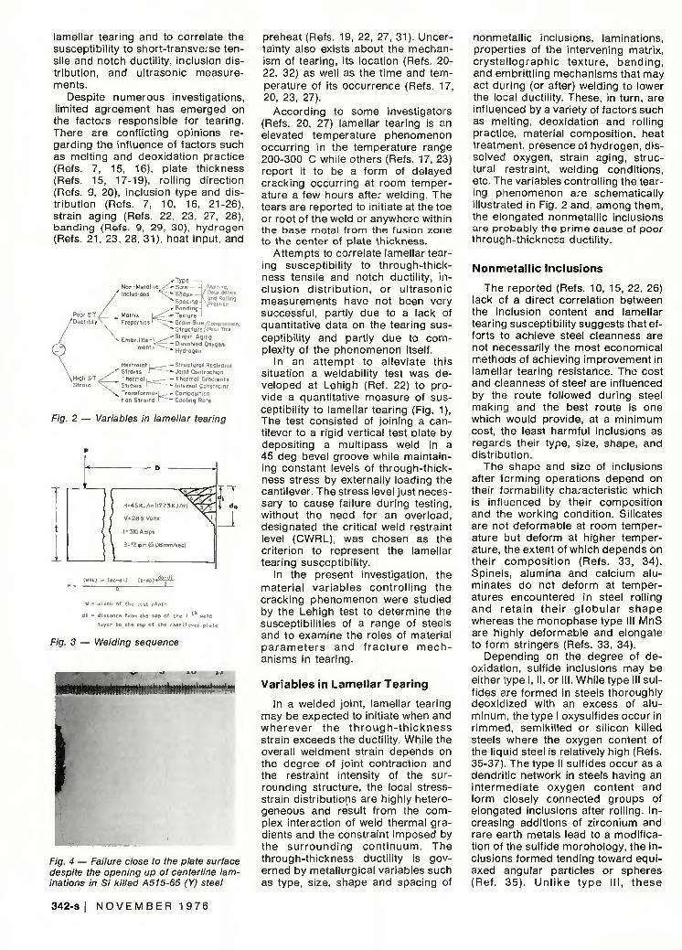
Fig. 1 — Lehigh lamellar tearing fixture
off-shore structures (Ref. 8), boilers (Refs. 8, 10) and nuclear power plants (Ref. 11). Though, in most cases, the r isk of t ea r i ng can be avo ided through proper modif ications to joint design and welding condit ions (Refs. 12, 13), there are situations where the only choice is to select a costlier material having a high resistance to tearing.
Thus, the problem of lamellar tearing has aroused much concern (Refs. 1-4, 14) among des igners, steel manufacturers and fabricators; and research efforts have been aimed towards developing weldability tests to assess material susceptibil ity to
WELDING RESEARCH S U P P L E M E N T I 341-S
lamellar tearing and to correlate the susceptibil i ty to short-transverse tensile and notch ductility, inclusion distr ibution, and ultrasonic measurements.
Despite numerous investigations, limited agreement has emerged on the factors responsible for tearing. There are confl icting opinions regarding the influence of factors such as melting and deoxidation practice (Refs. 7, 15, 16). plate thickness (Refs. 15, 17-19), rolling direction (Refs. 9, 20), inclusion type and distr ibution (Refs. 7, 10, 16, 21-26), strain aging (Refs. 22, 23, 27, 28), banding (Refs. 9, 29, 30), hydrogen (Refs. 21 , 23, 28, 31), heat input, and
Poor ST /Duct i l i ty '
/ l /el i.n,. Deoxidation
t ond Rolling " \Practice
y-Type Non-Metall ici^i--Size -Inclusions r ^ - Shape
Spacing •• Banding
Matrix U < ----- Texture Properties ' '^— Grain Sizer/Comp3sil
^ Structure NHeot Tmt r K ..,,. i - *" Strain Aging Embrit t le-L—'^ r. 1« , k~. -Dissolved Oxygen ment I - - _ , , _, ' * Hydrogen
High S T / Strain \
Restraint L==r—— Structural Restraint y " Strains H "*• Joint Contraction
Thermal i __-—- Thermal Gradients Strains 1 " ~ Internal Constraint
N^ Transforma-i,^--Compositicn tion Strains P ^ - Cooling Rate
Fig. 2 — Variables in lamellar tearing
H=45KJ/m{l773KJ/m)
V= 28 5 Volts
1 = 310 Amps
S = I2 ipm (5 08 mm/sec)
;T l d.
(URL) . (do-dl) ( t -do)*
1 distance from the top of the i weld
layer to the top of the cantilever plate
Fig. 3 — Welding sequence
Fig. 4 — Failure close to the plate surface despite the opening up of centerline laminations in Si killed A515-65 (Y) steel
preheat (Refs. 19, 22, 27, 31). Uncertainty also exists about the mechanism of tearing, its location (Refs. 20-22, 32) as well as the t ime and temperature of its occurrence (Refs. 17, 20, 23, 27).
According to some investigators (Refs. 20, 27) lamellar tearing is an elevated temperature phenomenon occurr ing in the temperature range 200-300 C while others (Refs. 17, 23) report it to be a form of delayed cracking occurr ing at room temperature a few hours after welding. The tears are reported to initiate at the toe or root of the weld or anywhere within the base metal f rom the fusion zone to the center of plate thickness.
Attempts to correlate lamellar tearing susceptibil ity to through-thickness tensile and notch ductility, inc lus ion d is t r ibu t ion , or u l t rasonic measurements have not been very successful, partly due to a lack of quantitative data on the tearing susceptibil ity and partly due to complexity of the phenomenon itself.
In an at tempt to al leviate this situation a weldabil ity test was developed at Lehigh (Ref. 22) to provide a quantitative measure of susceptibility to lamellar tearing (Fig. 1), The test consisted of joining a cantilever to a rigid vertical test plate by deposit ing a multipass weld in a 45 deg bevel groove while maintaining constant levels of through-thickness stress by externally loading the cantilever. The stress level just necessary to cause failure during testing, without the need for an overload, designated the critical weld restraint level (CWRL), was chosen as the criterion to represent the lamellar tearing susceptibil ity.
In the present investigation, the mater ia l var iables cont ro l l ing the cracking phenomenon were studied by the Lehigh test to determine the susceptibil it ies of a range of steels and to examine the roles of material p a r a m e t e r s and f r a c t u r e m e c h anisms in tearing.
Var iables in Lamel lar Tear ing
In a welded joint, lamellar tearing may be expected to initiate when and whe reve r the t h r o u g h - t h i c k n e s s strain exceeds the ductil ity. While the overall weldment strain depends on the degree of joint contraction and the restraint intensity of the surrounding structure, the local stress-strain distributions are highly heterogeneous and result f rom the complex interaction of weld thermal gradients and the constraint imposed by the sur round ing con t i nuum. The through-thickness ductility is governed by metallurgical variables such as type, size, shape and spacing of
nonmetall ic inclusions, laminations, propert ies of the intervening matrix, c rys ta l lograph ic texture, band ing , and embritt l ing mechanisms that may act during (or after) welding to lower the local ductility. These, in turn, are influenced by a variety of factors such as melt ing, deoxidation and rolling practice, material composi t ion, heat treatment, presence of hydrogen, dissolved oxygen, strain aging, structural restraint, welding condit ions, etc. The variables controll ing the tearing phenomenon are schematically illustrated in Fig. 2 and, among them, the elongated nonmetall ic inclusions are probably the pr ime cause of poor through-thickness ductil ity.
Nonmeta l l ic Inclusions
The reported (Refs. 10, 15, 22, 26) lack of a direct correlation between the inclusion content and lamellar tearing susceptibil ity suggests that efforts to achieve steel cleanness are not necessarily the most economical methods of achieving improvement in lamellar tearing resistance. The cost and cleanness of steel are influenced by the route fol lowed during steel making and the best route is one which would provide, at a min imum cost, the least harmful inclusions as regarcs their type, size, shape, and distr ibut ion.
The shape and size of inclusions after forming operations depend on their formabil i ty characteristic which is in f l jenced by their composit ion and the working condit ion. Silicates are not deformable at room temperature but deform at higher temperature, the extent of which depends on their compos i t ion (Refs. 33, 34). Spinels, alumina and calcium alu-minates do not deform at temperatures encountered in steel rolling and re ta in the i r g l o b u l a r shape whereas the monophase type III MnS are highly deformable and elongate to form stringers (Refs. 33, 34).
Depending on the degree of deoxidation, sulfide inclusions may be either type I, II, or III. While type III sulfides are formed in steels thoroughly deoxidized with an excess of aluminum, the type I oxysulfides occur in r immed, semiki l led or sil icon kil led steels where the oxygen content of the liquid steel is relatively high (Refs. 35-37) The type II sulfides occur as a dendrit ic network in steels having an in termedia te oxygen content and form closely connected groups of elongated inclusions after roll ing. Increasing addit ions of zirconium and rare earth metals lead to a modif ication of the sulfide morphology, the inclusions formed tending toward equiaxed angular particles or spheres (Ref. 35) . Un l i ke t ype I I I , t hese
342-s I N O V E M B E R 1 9 7 6
'al loyed' sulfides resist deformation and retain their globular shape. Injection of si l icon-calcium, a luminum-calcium or misch metal under a highly basic slag is reported (Ref. 38) to reduce sulfur contents to below 0.005 percent.
In Si killed steels, the major inclusions are the mult iphase silicates, while the minor ones are type I sulfides and simple oxides. With simultaneous Si-AI deoxidation the inclusions formed display a wide range of composit ion and morphology due to complexity of the reactions and are of the type M x A y S z (manganese aluminum silicates), A y S z (mullite) and a mixture of type I and III sulfides (Ref. 39). If Al deoxidation is carried out before Si addit ion, the major inclusions are the monophase type III sulfides and the minor ones are alum ina , sp ine ls and c a l c i u m a lu -minates. One can, thus, anticipate lamellar tearing to initiate at the silicates in Si killed and semikil led steel and at the sulfides in an Al killed steel.
The propensity for void formation depends on the differential thermal expansion characteristics between the inclusion and steel matrix. Where the inclusions contract more than the matrix, as with sulfides and iron oxides, voids tend to form; but if the inclusions contract less than the matrix, as with silicates, tessellated stresses are generated (Refs. 40, 41).
Among the techniques available for inclusion count ing, the Quantimet is reported (Refs. 42, 43) to give accurate and reproduc ib le measurements. Nevertheless, at the magnifications normally employed for the assessment of steel cleanness, it is not possib le to account for the smaller inclusions — especially the oxides — which may exert significant influence on the lamellar tearing susceptibility. In some steels, especially the Al killed type, longitudinal streaklike defects containing aligned clusters of small alumina inclusions occur which apparently result f rom reox-idation during teeming and get entrapped in the ingot during solidif ication. Such defects may not be included in the Quantimet data and the steel quality may be overestimated.
Beside the effects of inclusions and laminations, other factors like banding, c rys ta l lograph ic tex ture and matrix embrit t lement may play a sign i f i c a n t r o l e in e n h a n c i n g t h e mechanical anisotropy of rolled produc ts . Wh i l e the s i gn i f i cance of banding with regard to lamellar tearing is not es tab l i shed yet, the through-thickness ductil ity is reported (Refs. 29, 45) to drop with an increase in the degree of banding. A homogenizing treatment has been
reported (Refs. 15, 16, 26, 29, 45) to eliminate the effects of banding, but Jatczak et al (Ref. 46) and Grange (Ref. 47) conc luded that homo-g e n i z a t i o n c a u s e s on l y s l i g h t , commercial ly insignificant improvements in the transverse ductil ity and impact strength.
Some steels, especially the controlled rolled type, have been reported (Refs. 48-50) to exhibit periodic splitting parallel to the rolling plane and this has been attributed to cleavage along textured ferrite bands (Ref. 48), tearing along deformed ferrite grain boundar ies conta in ing numerous carbides (Ref. 49) and separation along embrit t led sulfide interfaces (Ref. 50). Splitt ing is reported (Ref. 48) even among the rare earth treated steels containing low sulfur levels with shape control. Also, the habit planes of mar tens i te laths, formed from unrecrystall ized austenite, tend to have preferred orientation due to the texture in the parent austenite and this may contribute to splitting in the matrix.
The matrix l igament separating the inclusion voids may be embri t t led, either during or after welding, by factors such as strain aging, dissolved oxygen, hydrogen, etc., thus facilitating lamellar tear initiation. Jubb et al (Ref. 27) have shown that in mult ipass welds, the HAZ of the parent material passes through a temperature range where limited ductility combined with a tendency to strain aging is likely to be experienced. The maximum strain aging is found to develop at temperatures in the range of 250-300 C. The strain aging may rapidly embr i t t le the matr ix l igaments separating the inclusion voids so that these l igaments fracture at low strains. As little as 20-30 ppm of oxygen in solution is reported (Ref. 51) to produce a marked intergranular embrit t lement of iron without a significant rise in the yield stress and increasing quantities of oxygen are f o u n d to be p rog ress i ve l y e m britt l ing.
There is limited evidence (Refs. 21 , 23, 28) to suggest that lamellar tear-
A l - k i l l e d Mil 16113C(T)-1" S i A-285(M)-• i • ••'..
\
Root
S i - k i l l e d A515-70(G)-2 1/2" A l - k i l l e d Mi ] U 1i 3C(J) -2" S i - k i lied A-36(Y)-2"
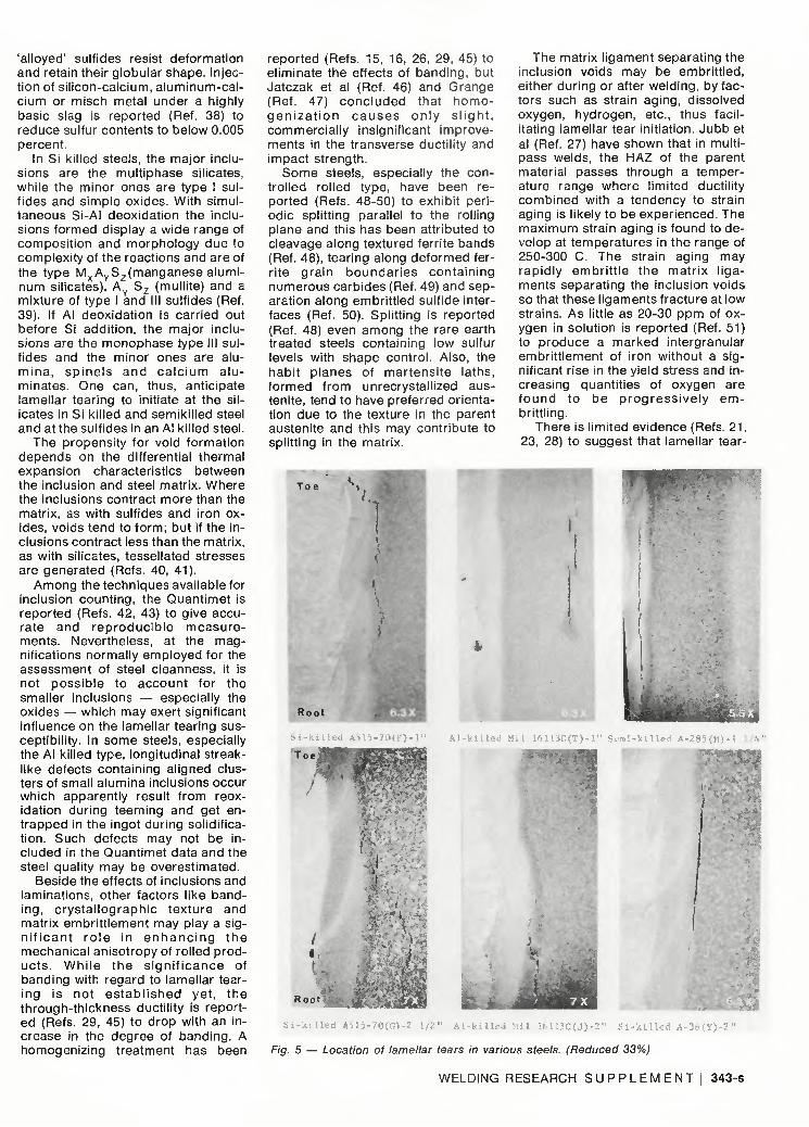
Fig. 5 — Location of lamellar tears in various steels. (Reduced 33%)
WELDING RESEARCH S U P P L E M E N T ! 343-s
CO
CD C
5
<D
o i q 1 o
a CJ
o
(1) - CD
t 0 2 r -O CO T -
o o o 1 o d d
0) _ . _ - < » O > r- O § CO UO CO CO 2 O r - O O CO O O O O O
O O O O O
> r - >
I I I I I
O
- - O o CO IT) N- t— T - - 5 s t n t M i O t - ^ O O O O O CO
d o d o d o
O
o O ) O O r -O O
t n CM co CO "0" -M" CM
O v- o o o o o o
C M S r -CV C O N
o o o o o o
T - CO 0 0 CO
o o o o
CO t - CJ) CO CO CM CO OJ
o o o o o o o o
o LO LO
o o o o
o o r~ •* CO N ^ LD
o o o o o o o o
CM O ) CM C O I O N
o o o o o o
CO I -r - • *
o o o o
C V O T T -
S LO CD CD
o o o o o o o o
r*- CM o o o o
LO CO CM S
O O O r-O O O o
CO CM LO
i - o o o o o
CM CM T - O O O
' t N W
o o o -a-o o o o
CO t 1 CJ
V V
LO LO O O O O
LO LO LO LO O O O O
O O o o
LO LO CM O O O O O O
LO O O 1 -
O o
CO t S CN LO t f ^ f CO O o O O
V V V V V V V V
o 5 r-J O
LO CM
oo r~ LO ^r i - O O CNJ
•M-CM i - CO
CO o o
CO T - O CM O
CO LO LO 0 0 CO t - > - O C V
o
(/) o Q E 0 u
o
CO CM
o o
CM - i — T - O
N CO CM i n O O O T -
LO N I N CO i - © O t -
[N . * 1 -
o o o V
CO T - CM
i - o o
O ) T -
o o V
* t f T -i - o
C O O N C O O r - 1 - O
i - i - o n T - T - CM O
r- r— o> •* i -CM CM r~ CM CM co o o i - o o o
i - L O O CM 1 - r-O O O
CM T -O T -O O
LO LO LO CO
O O o o o o o o
CM T - CO O 7 - T -O O O
o
>, n
X E
o
ttT
a
^-B
cl> T5
0
o
W CM CM
o>
ra " ' •
LL
s
CO o CM =
' OT
-a CD
o a <D DC
X
^T CM
* o c
JxC
c_ J
o CJ
CD
ra
LL.
z o
i n CM
a cl) X4
0
'.) CU LL
I I
CO CM
• a CD
c o Q . CD
rr
>
O) C\l
11 CD
•f-0 a. CD
LL
V
r— "» CM r-
CD
X3 3 CD r -
T_ ca o * ; a j a CD CO
r r LL
> - CL
<ji i - i - co cn o T - CM CNJ CM i - CO o o o o o o
•si- 1 - o> co - i - o O i - O O i - i -o o o o o o
CD
CD
W M- CO CO CO - Q CM CO h - LO
CD r -
o t r r-N O C O
1 - T -
CD
B M - M " W CM O ) ^ t r LO LO - Q CM O CM CO
a i r - r - r - r -
O CT) 7=- -sj- CO LO LO C\J CNJ •— CSJ CNJ i - i -
• • £ ' • • •
ra 1
cn LL
ra 11 Cl 01 L L
• D C CD g E O O c a . . * CD C
t r 3
-o TO 0 0 T— T-O O Q . Q . CD CD
CC cc
a 11 a m
LL.
a ai
a
CD
CO
1 0)
JO CO
h-CD
C c
"ra
a> ra
ci
^ ^
o LO CO CO CM CO < <
r - CM
CO CM T - CO
CD —
JO o o io
• i n L O i r>
LO LO LO
u_ < < <
CO -st LO CO
CNJ CNJ £
5 CO LO CO T - CO i
to co X < < LU
h - 0 0 a>
CO LO
a a CO CO CO CO CM CM < <
O i -
CO LO r - C M r - r - T -
O O CO CO
O r- T - T -r^ r - i - T -
* i - ^ CD CD co CM ir LO LO = =
< < 5 5
CM CO td - LO
a C3 0 0
LO
<
CD 00 Z- 00 CO I— CO
CO P 111 a)
CO
rr
CT 0 0 CO LO
<
<1> CD
to
N
CD O
E 3 t a a>
e to S S E S
i i ' Z ° cc B a c 3 2 1
t-
jh
<I>
E
7*J
4)
in
3 4 4 - S | N O V E M B E R 1 9 7 6
ing is a form of delayed cracking occurring at room temperature a few hours after welding. Several investigators (Refs. 52-55) have reported on the beneficial effect of sulfides which, acting as hydrogen sinks, tend to lower the hydrogen activity in the lattice and, thus, reduce the likelihood of underbead cracking. However, if voids and microcracks are formed around inclusions, as is the case in lamellar tearing, the presence of occluded hydrogen may increase the likelihood of subsequent propagation by hydrogen assisted cracking (Refs. 55, 56).
Materials and Procedure
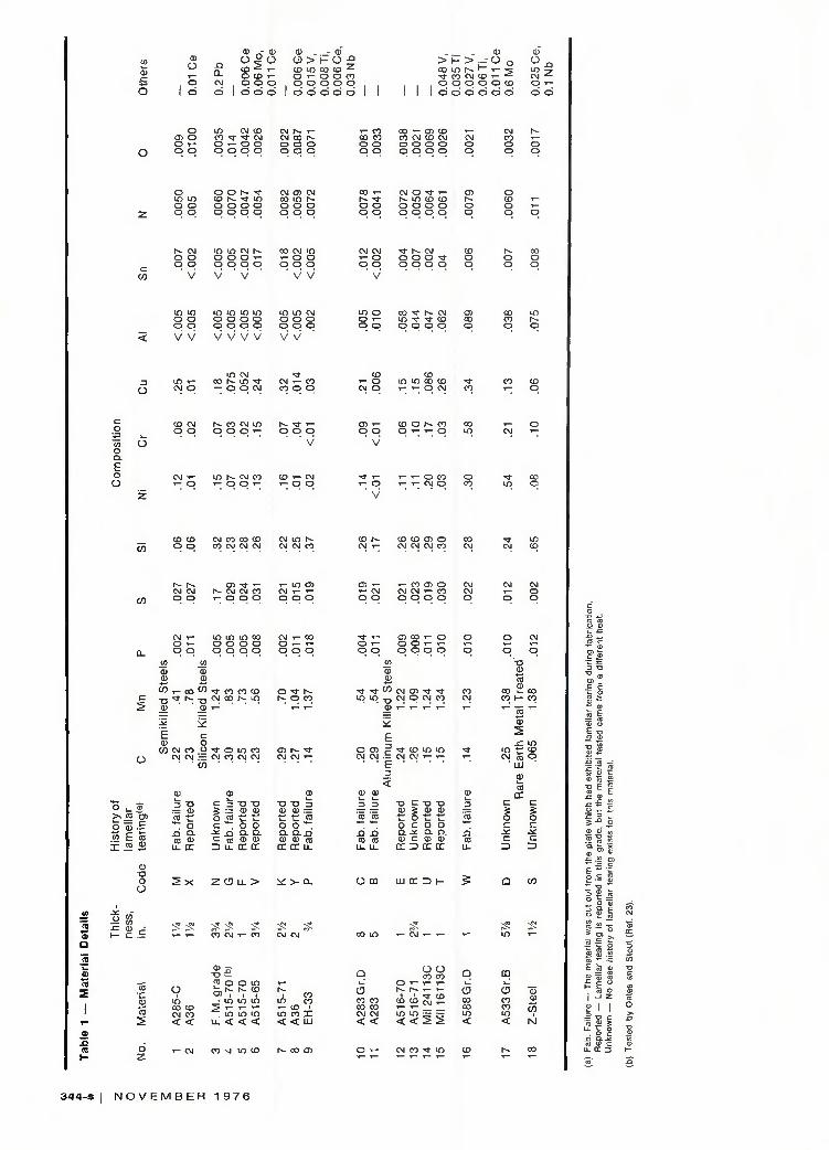
A range of materials which included two semikilled, eight silicon killed, six aluminum killed, one rare earth treated and one leaded-sulfurized steel, with the thickness ranging from 18 mm to 400 mm (3/4 in. to 8 in.) were tested to evaluate their tearing susceptibility. These steels were supplied by various manufacturers and fabricators — some coming from portions of a structure that had displayed lamellar tearing during actual fabrication, some belonging to grades that have had reported histories of lamellar tearing and some that have had no known history of lamellar tearing. The material details are presented in Table 1.
The lamellar tearing susceptibilities of the various steels were determined with the Lehigh test procedure outlined by Oates and Stout (Ref. 22). This test was developed to provide a simple and effective means of evaluating the lamellar tearing susceptibil ity of various materials through the application of an external load to supplement the weld thermal and restraint stresses. The external load was increased proportionally to the cross sectional area of the weld after each weld layer had cooled to room temperature so as to maintain a given level of through-thickness stress, called the weld restraint level, which was characteristic of each test. The load required was calculated using the simple formula given in Fig. 3 and the restraint level just enough to cause failure during welding, called the CWRL, was used as the susceptibility criterion.
In determining this criterion, care was taken to see that plates less than 38 mm thick were stiffened by welding a 25 mm thick back-up plate to them so that the longitudinal stresses due to bending between the restraining bolts was small compared to the through-thickness stresses. Thus, the CWRL could be related to the material parameters without having to consider the variable effects introduced
through changes in the plate stiffness (thickness).
An automatic gas metal-arc (GMA) welding process was used and the welding conditions employed are listed in Table 2. The extent and nature of subcritical tears were studied by metallographic examination of sections taken from the specimens tested just below the CWRL and microhardness measurements were carried out at regions around the tears to gain additional understanding of the factors influencing tear location.
The inclusion distributions in the various steels were evaluated using the Quantimet 360. Areas approximately 5 mm below the plate surface were scanned as the tears have been observed to lie mostly in this zone. Fifty fields were scanned in each section and a minimum of four sections were examined for each material so as to give adequate sampling. The average values of area fraction (A), aspect ratio (A ) , number of inclusions (N), inclusion length (L) and the longest inclusion in each field (L x ) were determined. The inclusions were identified both from the polished sections, using the electron microprobe, as well as from the fracture surface, using the energy dispersive spectrometer (EDS) associated with the SEM. The oxygen contents of the steels were determined by the vacuum fusion method and represent both dissolved and combined oxygen. Fractographic studies were carried out on the SEM by examining various regions on the fracture surface and stereopictures were taken to assist in better interpretation of the fracture features.
Results
Behavior of the Various Steels
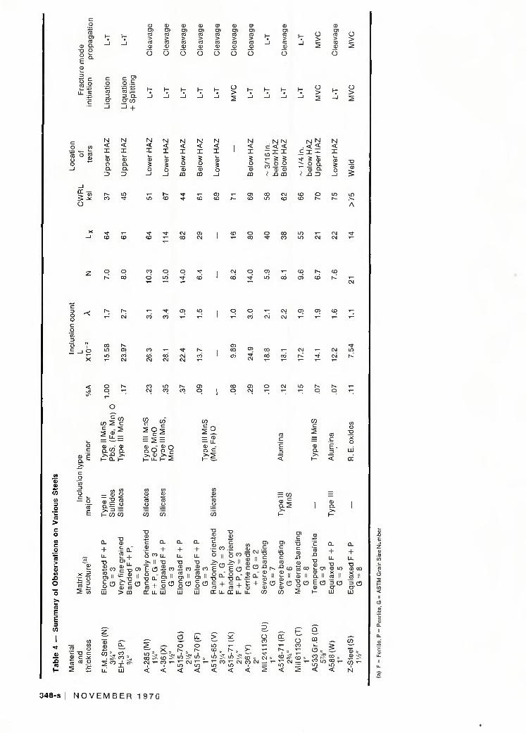
The Lehigh lamellar tearing test results are presented in Table 3 and
the susceptibility of the various steels are summarized in Table 4 together with information on their composition, matrix structure, inclusion type and distribution, tear location, fracture mode, etc. From Table 4 it can be seen that different heats of steel of the same grade display a wide variation in tearing susceptibility.
For instance, the susceptibility (CWRL) of Si killed A515-70 grade varied from 44 ksi (303 MPa) for the G-heat to 61 ksi (421 MPa) for the F-heat to 71 ksi (490 MPa) for the K-heat. The 80 mm (3.15 in.) thick A515-65 (V) plate showed a high resistance to tearing despite a heavy centerline lamination and, though the
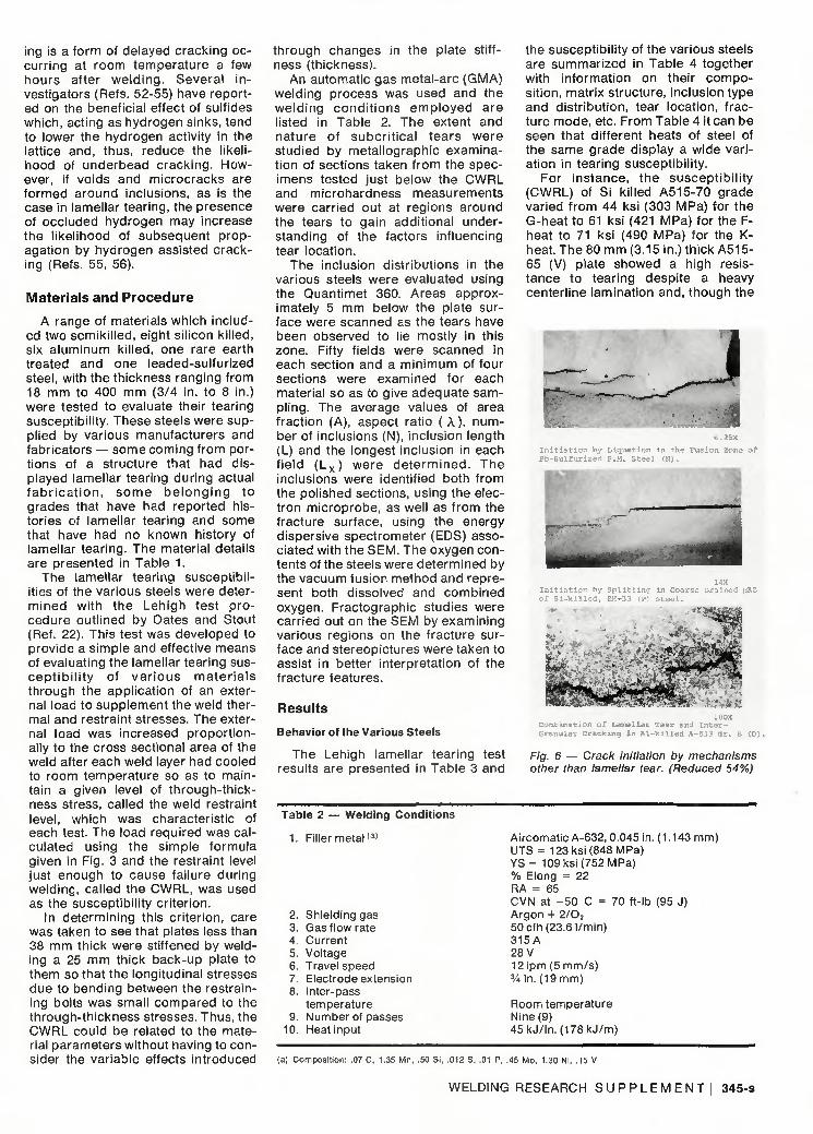
I n i t i a t i o n by L iqua t ion in the Fusion Zone of Pb-Sul fur i2ed F.M. S t ee l (N).
I n i t i a t i o n by S p l i t t i n g in c o a r s e Grained HAZ
100X Combination of Lamellar Tear and I n t e r -Granular Cracking in A l - k i l l e d A-533 Gr. B (D)
Fig. 6 — Crack initiation by mechanisms other than lamellar tear. (Reduced 54%)
Table 2 — Welding Conditions
1. Filler metal(a)
2. 3. 4. 5. 6. 7. 8.
9. 10.
Shielding gas Gas flow rate Current Voltage Travel speed Electrode extension Inter-pass temperature Number of passes Heat input
Aircomatic A-632, 0.045 in. (1.143 mm) UTS = 123 ksi (848 MPa) YS = 109 ksi (752 MPa) % Elong = 22 RA = 65 CVN at - 50 C = 70 ft-lb (95 J) Argon + 2/02
50 cfh (23.6 l/min) 315A 28 V 12 ipm (5 mm/s) 3A in. (19 mm)
Room temperature Nine (9) 45kJ/in. (178kJ/m)
(a) Composition: .07 C, 1.35 Mn, .50 Si, .012 S, .01 P. .45 Mo, 1.30 Ni, .15 V
WELDING RESEARCH S U P P L E M E N T ! 345-s
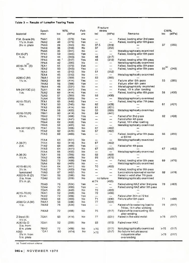
Table 3 — Results of Lamellar
Material
F.M. Grade (N) 1 % in. f rom 3% in. plate
EH33 (P ) % in.
(a) A516-70 (E)
1 in.
A285-C(M) VA in.
Mi l -24113C(U) 1 in.
A515-70(F) 1 in.
A516-70(R) 2% in.
Mi l -16113C(T) 1 in.
A-36(Y) 2 in.
A-36(X) 114 in.
A515-65(V) 3VA in. laminated
A533Gr .B (D) 2 in. f rom 5% in. pi.
A515-70(K) 21/2 in.
A 5 8 8 G r . A ( W ) 1 in.
Z Steel (S) ~\V2 i n .
A283Gr .D 3 in. f rom 8 in. plate
A283 2% in. f rom 5 in. plate
Speci men
7NA1 7NA2 7NA3 7NA4 7NA5 7PA1 7PA2 7PA3 7PA4 7EA1 7EA2 7EA3 7EA4 7MA1 7MA2 7MA3 7MA4 7UA1 7UA2 7UA3 7UA4 7FA1 7FA2 7FA3 7FA4 7RA1 7RA2 7RA3 7RA4 7RA5 7TA1 7TA2 7TA3
7TA4 7YA1 7YA2 7YA3 7YA4 7XA1 7XA2 7XA3 7XA4 7VA1 7VA2 7VA3 7DA1 7DA2
7DA3 7DA4 7DA5 7KA1 7KA2 7KA3 7WA1 7WA2
7WA3
7SA1
7BA1
7BA2 "CA1
Teari
ksi
55 40 28 36 35 50 44 46 42 55 50 45 45 52 60 56 48 64 60 57 56 65 50 60 58 60 72 64 62 58 56 62 68
64 60 68 64 66 56 68 72 68 64 70 67 56 52
76 72 65 52 72 68 56 76
72
60
52
72 60
ing Tests
WRL (MPa)
(379) (276) (193) (248) (241) (345) (303)
' (317) (290) (379) (345) (310) (310) (359) (414) (386) (331) (441) (414) (393) (386) (448) (345) (414) (400) (414) (496) (441) (428) (400) (386) (428) (469)
(441) (414) (469) (441) (455) (386) (469) (496) (469) (441) (483) (462) (386) (359)
(524) (496) (448) (359) (496) (469) (386) (524)
(496)
(414)
(359)
(496) (414)
Failure
Yes Yes No No No Yes No Yes No Yes Yes No No No Yes Yes No Yes Yes No No
Yes No No No No Yes Yes Yes No No No
Yes
No No Yes No No No No Yes No No Yes No No No
Yes Yes No No
Yes No No Yes
No
No
No
No No
Fracture stress
ksi
— 37.5 37
— — 46 45
— — — 51
— 53
— — — — — 58
— — 62 61 53 64
— — — — 67 67
—
— 67
— 67
— 68 69
— — 70
— — —
no 1 at 74
— — 70 72
— 71 77
—
75
77
83
>75
>75
(MPa)
— —
(259) (255)
— —
(317) (310)
— — —
(352)
— (365)
— — — — —
(400)
— —
(428) (421) (-365) (441)
— — — —
(462) (462)
—
— (462)
— (462)
— (469) (476)
— —
(483)
— — —
ailure (495)
— —
(483) (496)
— (490) (531)
(517)
(531)
(572)
(517) (517)
Remarks
Failed, loading after 3rd pass Failed, loading after 6th pass
— —
Metal lographical ly examined Failed, loading after 6th pass
— Failed, loading after 9th pass Metal lographical ly examined Failed, loading after 8th pass Failed, loading after 9th pass
— Metal lographical ly examined
— Failure after 6th pass Failure after 6th pass Metal lographical ly examined Failed, 10 h after loading Failed, loading after 6th pass
— Metal lographical y examined Failed, loading after 7th pass
— —
Metal lographical y examined
— Failed after 2nd pass Failed after 4th pass Failed, 10 h after loading Metal lographical ly examined
— —
Failed, loading after 9th pass at 64 ksi
Metal lographical ly examined
— Failed after 4th pass
— Metal lographical ly examined
— —
Failed, loading after 8th pass Metal lographical ly examined
— Failed, loading after 9th pass Laminations opened at center Failed in weld after 7th pass Metal lographical ly examined
Failed along HAZ after 3rd pass Failed along HAZ after 5th pass
— —
Failed after 24 h a t 72 ksi Failure after 6th pass
— Failed while restor ing load to
76 ksi, 15 h after welding Failed while over loading 18 h
after welding Failed in the weld metal
Failed near HAZ
Metal lographical ly examined No fai lure but ultrasonic
indications after overloading
CWRL ksi
37
(a) 5 0 "
53
58
61
62
66
67
69
69
70
71
75
> 7 5
> 7 5
>75
(MPa)
(255)
(345)
(365)
(400)
(421)
(428)
(455)
(462)
(476)
(476)
(483)
(490)
(517)
(517)
(517)
(517)
(a) Tested without stiffener
346-s I N O V E M B E R 1 9 7 6
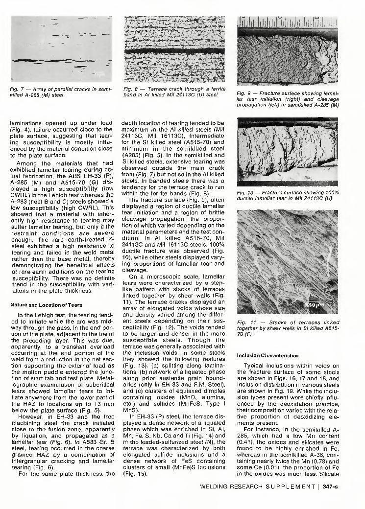
Fig. 7 — Array of parallel cracks in semi-killed A-285 (M) steel
r~W MS. '^^^k J^-
T * S —
mViiJ.iiija.jp urn
Fig. 8 — Terrace crack through a ferrite band in Al killed Mil 24113C (U) steel
*kiiJmJ&i& *****
Fig. 9 — Fracture surface showing lamellar tear initiation (right) and cleavage propagation (left) in semikilled A-285 (M)
laminations opened up under load (Fig. 4), fai lure occurred close to the plate surface, suggesting that tearing suscept ib i l i ty is most ly in f luenced by the material condit ion close to the plate surface.
A m o n g the mater ia ls that had exhibited lamellar tearing dur ing actual fabricat ion, the ABS EH-33 (P), A-285 (M) and A515-70 (G) d isplayed a high suscept ib i l i ty ( low CWRL) in the Lehigh test whereas the A-283 (heat B and C) steels showed a low susceptibil i ty (high CWRL). This showed that a material with inherently high resistance to tearing may suffer lamellar tearing, but only if the res t ra in t c o n d i t i o n s a r e seve re enough. The rare earth-treated Z-steel exhibited a high resistance to tearing and failed in the weld metal rather than the base metal, thereby demonstrat ing the beneficial effects of rare earth addit ions on the tearing susceptibil ity. There was no definite trend in the susceptibil i ty with variations in the plate thickness.
Nature and Location of Tears
In the Lehigh test, the tearing tended to initiate while the arc was midway through the pass, in the end portion of the plate, adjacent to the toe of the preceding layer. This was due, apparently, to a transient overload occurr ing at the end port ion of the weld from a reduction in the net section support ing the external load as the molten puddle entered the junction of start tab and test plate. Metallographic examinat ion of subcrit ical tears showed lamellar tears to initiate anywhere f rom the lower part of the HAZ to locations up to 13 mm below the plate surface (Fig. 5).
However, in EH-33 and the free machining steel the crack initiated close to the fusion zone, apparently by l iquation, and propagated as a lamellar tear (Fig. 6). In A533 Gr. B steel, tearing occurred in the coarse grained HAZ by a combinat ion of intergranular cracking and lamellar tearing (Fig. 6).
For the same plate thickness, the
depth location of tearing tended to be maximum in the Al kil led steels (Mil 24113C, Mil 16113C), intermediate for the Si kil led steel (A515-70) and m in imum in the semik i l led steel (A285) (Fig. 5). In the semiki l led and Si killed steels, extensive tearing was observed outside the main crack front (Fig. 7) but not so in the Al killed steels. In banded steels there was a tendency for the terrace crack to run within the ferrite bands (Fig. 8).
The fracture surface (Fig. 9), often displayed a region of ducti le lamellar tear initiation and a region of brittle cleavage propagat ion, the proportion of which varied depending on the material parameters and the test con-d i t ion . In Al k i l led A516-70, Mi l 24113C and Mil 16113C steels, 100% ducti le fracture was observed (Fig. 10), while other steels displayed varying proport ions of lamellar tear and cleavage.
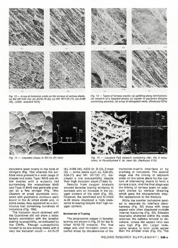
On a microscopic scale, lamellar tears were characterized by a steplike pattern with stacks of terraces linked together by shear walls (Fig. 11). The terrace cracks displayed an array of elongated voids whose size and density varied among the different steels depending on their susceptibility (Fig. 12). The voids tended to be larger and denser in the more s u s c e p t i b l e s tee ls . T h o u g h the terrace was generally associated with the inclusion voids, in some steels they showed the following features (Fig. 13): (a) splitting along laminations, (b) network of a l iquated phase along prior austenite grain boundaries (only in EH-33 and F.M. Steel), and (c) clusters of equiaxed dimples containing oxides (MnO, alumina, etc.) and sulfides (MnFeS, Type I MnS).
In EH-33 (P) steel, the terrace displayed a dense network of a l iquated phase which was enriched in Si, Al , Mn, Fe, S, Nb, Ca and Ti (Fig. 14) and in the leaded-sulfurized steel (N), the terrace was characterized by both elongated sulf ide inclusions and a dense network of FeS containing clusters of small (MnFe)S inclusions (Fig. 15).
Fig. 10 — Fracture surface showing 100% ductile lamellar tear in Mil 24113C (U)
Fig. 11 — Stacks of terraces linked together by shear walls in Si killed A515-70(F)
Inclusion Characteristics
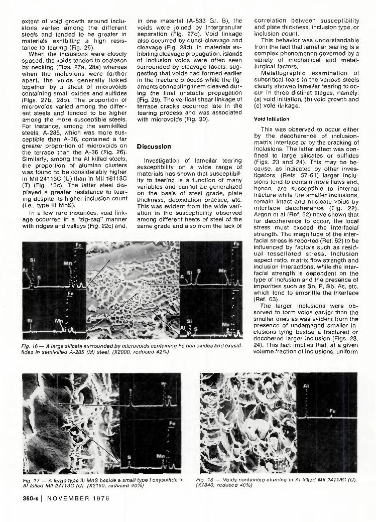
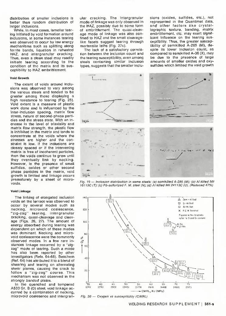
Typical inclusions within voids on the fracture surface of some steels are shown in Figs. 16, 17 and 18, and inclusion distr ibution in various steels are shown in Fig. 19. While the inclusion types present were chiefly influenced by the deoxidation practice, their composit ion varied with the relative proport ion of deoxidizing elements present.
For instance, in the semiki l led A-285, which had a low Mn content (0.41), the oxides and silicates were found to be highly enriched in Fe, whereas in the semikil led A-36, containing nearly twice the Mn (0.78) and some Ce (0.01), the proport ion of Fe in the oxides was much less. Silicate
WELDING RESEARCH S U P P L E M E N T I 347-s
CD Q -
-o o
I-o
8° 11 co
'c
1
c o
ro 3
cr
_ i
c p> o £ CO — 3 CL
CTOT
CD
Dl 03
> ra OJ
CD
Ol co > CO CD
CD
o> ra > ra CD
CD CT ra > ra CD
CD CT ra > (0 CD
o o
CD
ra
o o o o
ra O
CJ
C) > :>
ra > ra 0
n > >
o
o
RE
35
.O.
o
1
i i XI ra
x ^
C -a CD C
O > > o >
o
ro u o
_ l
U)
"o ra CD
N < X _ cp
a a Z>
N < I ^ CD
Q. Q .
Z>
o CO
.Ew
i ® 5
CD • CD
a.co a >, . •> ,
I - 0 . ( -
— CD
rr. "° a — • > , - >
h- CO
CO
ro
L
CO
Q -
+ CO
-a o>
I " £T3
< X
CD
g o
< I
CD g o
N < X g _o CD
CQ
N < X g C^
CD CQ
N < X
CD g O
N < X g CD
CQ
N N c < <
-ill CD CD
I - Q CD
N
• * g CD
^ 0 a CD C L
< X
g o
CD
I SS
T - ^ r c n
co c o T - : CO CM CM a> CM T ^
o •
Q . O Q . ^ > , CD > ^
2 ° = CD
r~. r-
CD T3
Q . 2
T3
B CD
L : G CD
CO C D
o .>• II
cn E CD II
a. +
CO u _
CL
+ C L
- o co§ S o I, c3 « -o ™
>. II * " li
o •a a.
-a n ID >•.. ^ II S £ c o 2 c o .£co E ° ECD ^CD g, II g, II g> II ° a: ° n - a CL
1 o c CD c CD CO > CQ LU
o LU cr UL cr
CT
ro ro CD a r~ •Q co 8 co S: II Lt 0
CT C
C
ra
CL
+ C L
+
CD
T3 O) Cp LO
S) II § °- -g Q.' I Li. o U 5 c D n O c + c , t + > C D > C D o C D £ C D = > C ! O u O u O u o T | j + „ CD CD O 0 (j-
LL OT OT 2 I - HI
"D 0 CO
I I CO l : CO II
o-° LU
W f .
2 « LL
O0 CO
T LU
CD LL — o o
co SS co ^ LO ^ LO : CM T - CO
< < CM ;
UJ L.
< <
> X. CJ — — CO CO T- ; -" . 1 -C O . S . > T-
L O ^ L O ^ c O a C M : ' T C O ' T r C M C O C M — r
11 ,T — O r - CO N- . i -
<° 5? CO = - i - CM — T
cn
O . ^ CO ^ 00 .
- CO LO °0 T~
0 = £ S
348-s I N O V E M B E R 1 9 7 6
* J> >"W
Fig. 12 — Array of inclusion voids on the terrace of various steels, (a) Mil 24113C (U): (b) A516-70 (E); (c) Mil 16113C (T); (d) A588 (W). (X200, reduced 52%)
Fig. 13 — Types ot terrace cracks: (a) splitting along laminations: (b) network of a liquated phase: (c) cluster of equiaxed dimples containing alumina: (d) array of elongated voids. (Reduced 52%)
Fig. 14 — Liquated phase in EH-33 (P) steel Fig. 15 — Liquated FeS network containing (Mn, Fe) S inclusions, in Pb-sulfurlzed F. M. steel (N). (Reduced 41%)
inclusions were mostly in the form of stringers (Fig. 19a) whereas the sul fides were present in a wide range of shapes and sizes. Type I MnS was often d u p l e x wi th a eu tec t i c ta i l surrounding the monophase MnS and Type III MnS was generally present as a fine stringer (Fig. 19b). Clusters of small aluminate inclusions with polyhedral contours were found in the Al killed steels and, in some cases, they appeared as a continuous trail containing hundreds of inclusions (Fig. 19d).
The inclusion count obtained with the Quantimet did not show a satisfactory correlation with the lamellar tearing susceptibility, as indicated by the CWRL. Though suscept ib i l i ty tended to be low among steels with a very low inclusion count — A515-70
(K), A588 (W), A533 Gr. B (D), Z steel (S) — some steels such as, A36-(X), A36-(Y) and Mil 16113C (T), displayed a low susceptibil ity despite their high inclusion count (Table 4).
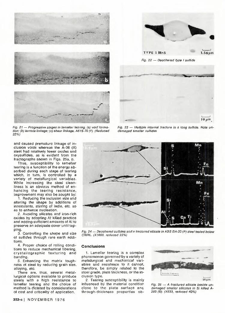
Resul ts f r o m oxygen ana lys is showed lamellar tearing tendency to increase with an increase in the oxygen content of the steel (Fig. 20). However, the semikil led and Si killed A-36 steels displayed a high resistance to tearing despite their high oxygen content.
Mechanism of Tearing
The progressive stages in lamellar tearing are shown in Fig. 21 for the Si killed A515-70 material. The first stage was void formation which occurred either by decoherence of the
i n c l u s i o n - m a t r i x i n te r face or by cracking of inclusions. The second stage was the linking of adjacent voids on the same plane by the rupture of intervening matrix to form a terrace crack. And the final stage was the linking of terrace tears on adjacent planes by ver t ical shear ing which gave the characteristic steplike appearance to the fracture.
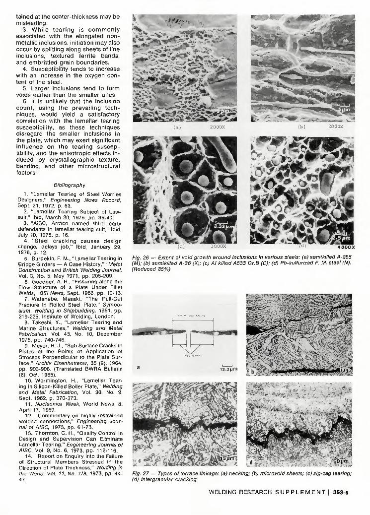
While the smaller inclusions tended to separate by interface decoherence (Fig. 22) those with large aspect ratio often displayed multiple internal fracturing (Fig. 23). Silicates invariably shattered within the voids whereas the sulfides tended to decohere, unless the aspect ratio was very high (Fig. 24). Larger inclusions tended to form voids earlier than the smaller ones (Fig. 25). The
WELDING RESEARCH S U P P L E M E N T , 349-s
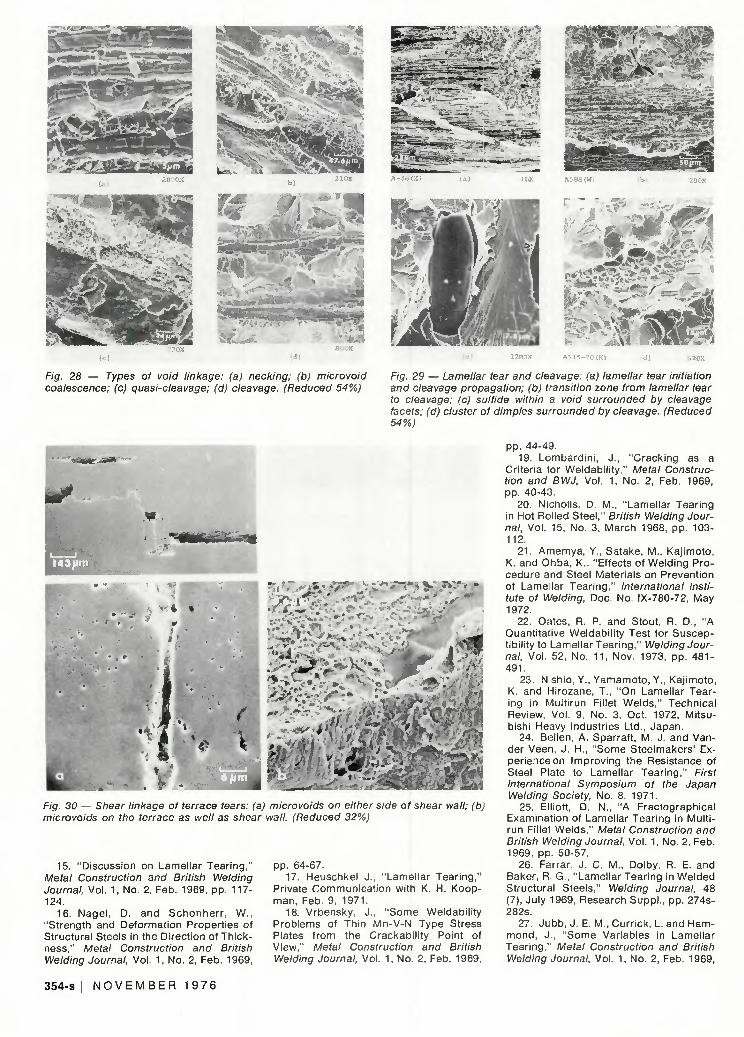
extent of void growth around inclusions var ied among the di f ferent steels and tended to be greater in materials exhibit ing a high resistance to tearing (Fig. 26).
When the inclusions were closely spaced, the voids tended to coalesce by necking (Figs. 27a, 28a) whereas when the inc lus ions were farther apart , the vo ids general ly l inked together by a sheet of microvoids containing small oxides and sulfides (Figs. 27b, 28b). The proport ion of microvoids varied among the different steels and tended to be higher among the more susceptible steels. For instance, among the semikil led steels, A-285, which was more susceptible than A-36, contained a far greater proport ion of microvoids on the terrace than the A-36 (Fig. 26). Similarly, among the Al kil led steels, the proport ion of alumina clusters was found to be considerably higher in Mil 24113C (U) than in Mil 16113C (T) (Fig. 13c). The latter steel displayed a greater resistance to tearing despite its higher inclusion count (i.e., type III MnS).
In a few rare instances, void linkage occurred in a "z ig-zag" manner with ridges and valleys (Fig. 22c) and,
in one material (A-533 Gr. B), the voids were joined by intergranular separation (Fig. 27d). Void linkage also occurred by quasi-cleavage and cleavage (Fig. 28d). In materials exhibiting cleavage propagation, islands of inclusion voids were often seen surrounded by cleavage facets, suggesting that voids had formed earlier in the fracture process while the ligaments connecting them cleaved during the final unstable propagation (Fig. 29). The vertical shear linkage of terrace cracks occurred late in the tearing process and was associated with microvoids (Fig. 30).
Discussion
Investigation of lamellar tearing susceptibil ity on a wide range of materials has shown that susceptibi lity to tearing is a function of many variables and cannot be generalized on the basis of steel grade, plate thickness, deoxidation practice, etc. This was evident f rom the wide variation in the susceptibil ity observed among different heats of steel of the same grade and also from the lack of
Fig. 16 — A large silicate surrounded by microvoids containing Fe rich oxides and oxysul-fides in semikilled A-285 (M) steel. (X2000. reduced 42%)
corre la t ion between suscept ib i l i ty and plate thickness, inclusion type, or inclusion count.
This behavior was understandable from the fact that lamellar tearing is a complex phenomenon governed by a variety of mechanical and metallurgical factors.
Meta l lograph ic examinat ion of subcritical tears in the various steels clearly showed lamellar tearing to occur in three distinct stages, namely: (a) void initiation, (b) void growth and (c) void l inkage.
Void Initiation
This was observed to occur either by the decoherence of inclusion-matrix interface or by the cracking of inclusions. The latter effect was confined to large silicates or sulfides (Figs. 23 and 24). This may be because, as indicated by other investigators, (Refs. 57-61) larger inclusions tend to contain more flaws and, hence, are susceptible to internal fracture while the smaller inclusions, remain intact and nucleate voids by inter face decoherence (Fig. 22). Argon et al (Ref. 62) have shown that for decoherence to occur, the local stress must exceed the interfacial strength. The magnitude of the interfacial stress is reported (Ref. 62) to be influenced by factors such as residual t esse l l a ted s t ress , i nc lus ion aspect ratio, matrix flow strength and inclusion interactions, while the interfacial strength is dependent on the type of Inclusion and the presence of impurit ies such as Sn, P, Sb, As, etc. which tend to embrit t le the interface (Ref. 63).
The larger inclusions were observed to form voids earlier than the smaller ones as was evident from the presence of undamaged smaller inclusions lying beside a fractured or decohered larger inclusion (Figs. 23, 24). This fact implies that, at a given volume fraction of inclusions, uniform
a^^inV' =3f"
Fig. 17 — A large type III MnS beside a small type I oxysulfide in Al killed Mil 24113C (U). (X2150, reduced 40%)
Fig. 18 — Voids containing alumina in Al killed Mil 24113C (U). (X1840, reduced 40%)
350-s I N O V E M B E R 1 9 7 6
distr ibution of smaller inclusions is better than random distr ibution of larger inclusions.
While, in most cases, lamellar tearing initiated by void formation around inclusions, in some instances tearing was observed to occur by low energy mechanisms such as splitt ing along ferrite bands, l iquation in reheated HAZ, and in tergranular c rack ing . Thus, even a clean steel may readily init iate tear ing accord ing to the condit ion of the matrix and its susceptibility to HAZ embritt lement.
Void Growth
The extent of voids around inclusions was observed to vary among the various steels and tended to be greater among those displaying a high resistance to tearing (Fig. 25). Void extent is a measure of plastic work done and is influenced by the inter-inclusion spacing, matrix flow stress, nature of second-phase part icles and the stress state. With an increase in the level of triaxiality and matrix flow strength, the plastic flow is inhibited in the matrix and tends to concentrate at the voids where the stresses are higher and the constraint is low. If the inclusions are closely spaced or if the intervening matrix is free of incoherent particles, then the voids continue to grow until they eventual ly l ink by neck ing. However, in the presence of small sul f ides, ox ides or other second phase particles in the matrix, void growth is l imited and linkage occurs prematurely by a sheet of micro-voids.
Void Linkage
The linking of elongated inclusion voids on the terrace was observed to occur by several modes such as neck ing , mic rovo id coalescence, " z i g - z a g " t ea r i ng , i n te rg ranu la r cracking, quasi-cleavage and cleavage (Figs. 26, 27). The amount of energy absorbed during tearing was dependent on which of these modes was dominant. Necking and micro-void coalescence were the commonly observed modes. In a few rare instances linkage occurred by a "z igzag" mode of tearing. Such a mode has also been reported by other investigators (Refs. 64-66). Beachem (Ref. 64) has attributed it to a blend of shearing and tearing on alternating shear planes, causing the crack to fo l low a " z i g - z a g " cou rse . Th is mechanism was not observed in the strongly banded plates.
In the quenched and tempered A533 Gr. B (D) steel, void linkage occurred by a combinat ion of necking, microvoid coalesence and intergran
ular c rack ing . The in tergranular mode of l inkage was only observed in the HAZ, possibly due to some form of embrit t lement. The quasi-cleavage mode of linkage was also confined to HAZ and the small cleavagelike facets suggest tearing through martensite laths (Fig. 27c).
The lack of a satisfactory correlation between the inclusion count and the tearing susceptibil ity, even among steels containing similar inclusion types, suggests that the smaller inclu
sions (oxides, sul f ides, etc.), not represented in the Quantimet data, a n d o t h e r f a c t o r s l i k e c r y s t a l lographic texture, banding, matrix embritt lement, etc. may exert significant influence on the tearing susceptibility. Thus, the greater susceptibility of semikil led A-285 (M), despite its lower inclusion count, as compared to semikil led A-36 (X), may be due to the presence of large amounts of smaller oxides and oxy-sulfides which limited the void growth
Fig. 19 — Inclusion distribution in some steels: (a) semikilled A-285 (M); (b) Al killed Mil 16113C (T): (c) Pb-sulfurized F. M. steel (N); (d) Ai killed Mil 24113C (U). (Reduced 47%)
-CWRL, KsKMPa)
Fig. 20 — Oxygen vs susceptibility (CWRL)
WELDING RESEARCH S U P P L E M E N T | 351-S
TYPE 1 MnS 1.56um
Fig. 22 — Decohered type I sulfide
19/jm
Fig. 21 — Progressive stages in lamellar tearing, (a) void formation: (b) terrace linkage: (c) shear linkage. A515-70 (F). (Reduced 22%)
Fig. 23 — Multiple internal fracture in a long sulfide. Note undamaged smaller sulfides
and caused premature l inkage of inclusion voids whereas the A-36 (X) steel had relatively fewer oxides and oxysulfides, as is evident from the fractographs shown in Figs. 25a, b.
Thus, suscept ib i l i ty to lamel lar tearing is a function of the energy absorbed during each stage of tearing which, in turn, is control led by a variety of meta l lurg ica l var iab les. While increasing the steel cleanliness is an obvious method of enhanc ing the tea r ing res i s tance , improvement may also be sought by:
1. Reducing the inclusion size and altering the shape by addit ions of innoculants, stirring of ladle, etc. so as to enhance nucleation.
2. Avoiding silicates and iron-rich oxides by adopting Al killed practice and adding sufficient amounts of Al to preserve an adequate cover until tapping.
3. Controll ing the shape and size of sulfides through rare earth additions.
4. Proper choice of rolling conditions to reduce mechanical f ibering, c r y s t a l l o g r a p h i c t e x t u r i n g a n d banding.
5. Enhancing the matrix toughness of steel by reducing grain size, alloying, etc.
There are, thus, several metallurgical options available to produce steels with a high resistance to lamellar tearing and the choice of method is dictated by considerations of cost and criticality of application.
Fig. 24 — Decohered sulfides and a fractured silicate in ABS EH-33 (P) steel tested below CWRL. (X1600, reduced 22%)
Conclusions
1. Lamellar tearing is a complex phenomenon governed by a variety of metallurgical and mechanical variables and resistance to it cannot, therefore, be simply related to the steel grade, plate thickness, or the inclusion type.
2. Tearing susceptibil ity is mainly influenced by the material condit ion c lose to the p la te su r f ace anc th rough- th ickness proper t ies ob -
19( jm
Fig. 25 — A fractured silicate beside undamaged smaller silicates in Si killed A-283 (B). (X533, reduced 40%)
352-s I N O V E M B E R 1 9 7 6
tained at the center-thickness may be misleading.
3. While tearing is commonly associated with the elongated non-metallic inclusions, initiation may also occur by splitting along sheets of fine inclusions, textured ferrite bands, and embrittled grain boundaries.
4. Susceptibility tends to increase with an increase in the oxygen content of the steel.
5. Larger inclusions tend to form voids earlier than the smaller ones.
6. It is unlikely that the inclusion count, using the prevailing techniques, would yield a satisfactory correlation with the lamellar tearing susceptibility, as these techniques disregard the smaller inclusions in the plate, which may exert significant influence on the tearing susceptibility, and the anisotropic effects induced by crystallographic texture, banding, and other microstructural factors.
Bibliography
1. "Lamel lar Tearing of Steel Worr ies Designers," Engineering News Record, Sept. 21 , 1972, p. 53.
2. "Lamel lar Tearing Subject of Lawsuit," Ibid, March 20, 1975, pp. 39-40.
3. "AISC, A rmco named th i rd party defendants in lamellar tearing suit," Ib id, July 10, 1975, p. 16.
4 . " S t e e l c r a c k i n g c a u s e s d e s i g n change, delays j ob , " Ib id, January 29, 1976, p. 12.
5. Burdekin, F. M., "Lamel lar Tearing in Bridge Girders — A Case History," "Metal Construction and British Welding Journal, Vol. 3, No. 5, May 1971, pp. 205-209.
6. Goodger, A. H., "Fissuring along the Flow Structure of a Plate Under Fillet Welds," BSI News, Sept. 1966, pp. 10-13.
7. Watanabe, Masaki, "The Pull-Cut Fracture in Rolled Steel Plate," Symposium, Welding in Shipbuilding, 1961, pp . 219-225, Institute of Weld ing, London.
8. Takeshi, Y., "Lamel lar Tearing and Marine Structures," Welding and Metal Fabrication, Vol. 43, No. 10, December 1975, pp. 740-746.
9. Meyer, H. J. , "Sub Surface Cracks in Plates at the Points of Appl icat ion of Stresses Perpendicular to the Plate Surface," Archiv Eisenhuttenw, 35 (9), 1964, pp. 903-908. (Translated BWRA Bulletin (6), Oct. 1965).
10. Wormington, H., "Lamel lar Tearing in Si l icon-Ki l led Boiler Plate," Welding and Metal Fabrication, Vol. 30, No. 9, Sept. 1962, p. 370-373.
11 . Nucleonics Week, Wor ld News, 8, Apr i l 17, 1969.
12. "Commentary on highly restrained welded connect ions," Engineering Journal of AISC, 1973, pp. 61-73.
13. Thornton, C. H., "Quali ty Control in Design and Supervis ion Can Eliminate Lamellar Tear ing," Engineering Journal of AISC. Vol. 9, No. 6, 1973, pp. 112-116.
14. "Report on Enquiry into the Failure of Structural Members Stressed in the Direction of Plate Thickness," Welding in the World, Vol, 11 , No. 7/8, 1973, pp. 44 -47.
A i cty^.&£* \SUMf»
33!' W IW
ooox 4 0 0 0 X
Fig. 26 — Extent of void growth around inclusions in various steels: (a) semikilled A-285 (M); (b) semikilled A-36 (X); (c) Al killed A533 Gr.B (D); (d) Pb-sulfurized F. M. steel (N). (Reduced 35%)
*m
zS-j^14&X* lLrJ*x~ 5-tW • K V
OF c *
•v^eS* 4> "SOJjrp
Fig. 27 — Types of terrace linkage: (a) necking; (b) microvoid sheets; (c) zig-zag tearing; (d) intergranular cracking
WELDING RESEARCH S U P P L E M E N T I 353-s
! S T J - : I - 7 s-zry& Srt .
- I * ^L-*^,?*,- .>* ~» % -S? '
F/g. 28 — Types of iro/'d linkage: (a) necking; (b) microvoid coalescence; (c) quasi-cleavage; (d) cleavage. (Reduced 54%)
fig. 30 — Shear linkage of terrace tears: (a) microvoids on either side of shear wall; (b) microvoids on the terrace as well as shear wall. (Reduced 32%)
15. "Discussion on Lamellar Tear ing," Metal Construction and British Welding Journal, Vol. 1, No. 2, Feb. 1969, pp. 117-124.
16. Nagel , D. and Schonher r , W., "Strength and Deformation Propert ies of Structural Steels in the Direction of Thickness," Metal Construction and British Welding Journal, Vol. 1, No. 2, Feb. 1969,
pp. 64-67. 17. Heuschkel J., "Lamel lar Tear ing,"
Private Communicat ion with K. H. Koopman, Feb. 9, 1971.
18. Vrbensky. J., "Some Weldabil i ty Problems of Thin Mn-V-N Type Stress Plates f rom the Crackabi l i ty Point of View," Metal Construction and British Welding Journal, Vol. 1. No. 2, Feb. 1969.
Fig. 29 — Lamellar tear and cleavage: (a) lamellar tear initiation and cleavage propagation; (b) transition zone from lamellar tear to cleavage; (c) sulfide within a void surrounded by cleavage facets; (d) cluster of dimples surrounded by cleavage. (Reduced 54%)
pp. 44-49. 19. Lombard in i , J. , "Crack ing as a
Criteria for Weldabi l i ty," Metal Construction and BWJ, Vol. 1. No. 2, Feb. 1969, pp. 40-43.
20. Nicholls, D. M., "Lamel lar Tearing in Hot Rolled Steel," British Welding Journal, Vol. 15. No. 3, March 1968, pp. 103-112.
2 1 . Amemya, Y., Satake, M., Kaj imoto, K. and Ohba. K.. "Effects of Welding Procedure and Steel Materials on Prevention
• '•" i ^ »»"-" • " ot Lame lar Tear ing," International Institute of Welding, Doc. No. IX-780-72, May 1972.
22. Oates, R. P. and Stout, R. D., "A Quantitative Weldabil i ty Test for Susceptibility to Lamellar Tear ing," Welding Journal, Vol. 52, No. 11, Nov. 1973, pp. 4 8 1 -491.
23. Nishio, Y.. Yamamoto. Y., Kaj imoto, K. and Hirozane. T., "On Lamellar Tearing in Mult i run Fillet Welds," Technical Review, Vol. 9. No. 3. Oct. 1972, Mitsubishi Heavy Industries Ltd., Japan.
24. Bellen, A. Sparraft. M. J. and Van-der Veen, J . H., "Some Steelmakers ' Experience on Improving the Resistance of Steel Plate to Lamellar Tear ing," First International Symposium of the Japan Welding Society, No. 8, 1971.
25. Elliott, D. N., "A Fractographical Examination of Lamellar Tearing in Mult i -run Fillet Welds," Metal Construction and British Welding Journal, Vol. 1, No. 2, Feb. 1969. pp. 50-57.
26. Farrar. J. C. M., Dolby, R. E. and Baker, R. G.. "Lamel lar Tearing in Welded Structural Steels," Welding Journal, 48 (7), July 1969, Research Suppl . , pp. 274s-282s.
27. Jubb, J. E. M., Curr ick, L. and Hammond, J., "Some Variables in Lamellar Tear ing." Metal Construction and British Welding Journal. Vol. 1, No. 2, Feb. 1969.
354 -s I N O V E M B E R 1 9 7 6
pp. 58-63. 28. Arita, Y. and Kaj imoto, K., "The
Study of Lamellar Tearing in Offshore Structure," Fourth Annual Offshore Technology Conference in Houston, Texas, May 1972.
29. Owen, W. S., Cohen, M. and Aver-bach, B. L., "The Influence of Ferrite Banding on the Impact Propert ies of Mild Steel," Welding Journal, 37 (8), Aug. 1958, Research Suppl . , pp. 368s-374s.
30. Farrar, J . C. M. and Dolby, R. E., "An Investigation into Lamellar Tearing, Metal Construction and British Welding Journal, Vol. 1, No. 2, Feb. 1969, pp. 32-34.
3 1 . Arak i , M., et al., "Crack ing in Mu l -t irun Fillet Welds," Nippon Kokan Technical Report-overseas, June 1974, pp. 25-35.
32. Nicholls, D. M., Wi lson, D. M. and J u b b , J . E. M., " C o r r e s p o n d e n c e on Lamellar Tear ing," British Welding Journal, Vol. 13, No. 5, May 1966, pp. 326.
33. Gol ikov, I. N., "Certain peculiarities in the format ion of oxide- inclusions revealed by complex analysis," in 'Product ion and Appl icat ion of Clean Steels,' ISI, Sp. report , ISI London, 1970, pp. 35-4 1 .
34. Keissl ing, R., "The Influence of Non-Metal l ic Inclusions on the Propert ies of Steel," J. Metals, Vol. 22, No. 10, Oct. 1969, pp. 48-54.
35. Little, J. H. and Henderson, W. J . M., "Effect of Sulf ide Inclusions on the A n i s o t r o p y of Duc t i l e C h a r p y Shel f Energy," in 'Effect of Second Phase Particles on the Mechanical Propert ies of Steel, ' ISI, Sp. Report, ISI, London, 1971, pp. 171-181.
36. Baker T. J. and Charles, J. A., "Morpho logy of Manganese Sulf ide in Steel," JISI, September 1972, pp. 702-6.
37. Baker, T. J. and Charles, J. A., "Deformat ion of Manganese Sulf ide Inclusions in Steel," Ibid, pp. 680-690.
38. Santen, S. and Ohman, B., "Techniques for obtaining extremely low con tents of sulfur in steel under oxidizing and reducing condi t ions," Clean Steel, v. 1, Report of the Royal Swedish Academy of Engineering Sciences, 169:1, 1971, pp. 7-19.
39. Pickering, F. B., "Effect of Processing Parameters on the Origin of Non-metallic Inclusions, in "Effect of Second Phase . . .," ISI, Sp. Report, ISI, London, 1970, pp. 75-91 .
40. Keissling, R. and Nordberg , H., " I n
f luence of Inclusions on the Mechanical Propert ies of Steel" in 'Product ion and App l i ca t i on of C lean Steels ' ISI, Sp . Report, ISI, London, 1970, pp. 179-185.
4 1 . Brooksbank, D. and Andrews, K. W., "Stress Fields Around Inclusions and Their Relation to Mechanical Propert ies," Ibid, pp. 186-198.
42. A l lmand, T. R. and Blank, J. R., "An Evaluation of the Quant imet for Assessing Non-Metal l ic Inclusions and Other Microscopical Features in Metals and Alloys," in 'Automatic Cleanness Assessment of Steel , " ISI, Sp. Report, No. 112, ISI, London, 1968, pp. 47-60.
43. Mel ford, "Design and Use of Automatic Instruments for Cleanness Assessment," Ibid., pp. 14-23.
44. Charpent ier, P. L. et al., "Black- l ine s u r f a c e d e f e c t s in a l u m i n u m - k i l l e d steels," Metals Technology, Vol . 2, part 2, February 1975, pp. 52 -61 .
45. Cairns, R. L. and Charles, J . A., "Banding in carbon and low-alloy steel — a brief review," Iron and Steel, Vol. 39, November 1966, pp. 511-515.
46. Jatczak, E. F., Girard i , D. J . and Rowland, E. S., "On Banding in Steel," Trans. A.S.M., Vol. 48, 1956, pp. 279-305.
47. Grange, R. A., "Effect of Micro-structural Banding in Steel," Metallurgical Transactions, Vol. 2, February 1971, pp. 417-426.
48. Coleman, T., Dulien, D. and Gouch, A., "The structure and propert ies of con trol led processed high strength ferr i te-pearlite steels," in Microstructure and Design of Alloys, Vol. 1, 1974, London, The Metals Society, pp. 70-74.
49. Hero, H., Evensen, J. and Embury, J . D., "The occurrence of delaminat ion in a control led rol led HSLA steel," Canadian Met. Quarterly, Vol. 14, No. 2, 1975, pp. 117-122.
50. Yen, C. M. and Stickels, C. A., "Lamel late fracture in 5150 steel processed by modif ied ausforming," Metallurgical Transactions, Vol. 1, Nov. 1970, pp. 3037-3047.
51 . Stoloff, N. S., "Effects of alloying on fracture character ist ics," Fracture, Vol. VI, Edited by Liebowitz, H., Academic Press, N.Y. 1969, pp. 1-81.
52. Boniszewski, T. and Moreton, Mrs. J . , "Effect of microvoids and manganese sulf ide inclusions in steel on hydrogen evo lu t ion and embr i t t l emen t , " British Welding Journal, Vol. 14, No. 6, June 1967, pp. 321-336.
53. Moreton, Mrs. J. , Coe, F. R. and
Boniszewski, T., "Hydrogen movement in weld metals," Metal Construction and British Welding Journal, Vol. 3, No. 5, May 1971, pp. 185-187.
54. Hewitt, J . and Murray, J. D., "Effect of sulfur on the product ion and fabr ication of C-Mn steel forg ings," Ibid, Vol. 1, No. 2, Feb. 1969, pp. 24 -31 .
55. Smith, N. and Bagnall , B. I., "The influence of sulfur on HAZ cracking of C-Mn steel welds," Ibid, pp. 17-23.
56. "Discussion of hydrogen induced cold crack ing, " Ibid. pp. 109-116.
57. Argon, A. S. and Im, J . , "Separat ion of Second Phase Particles in Sphero-dized 1045 Steel, Cu-0.6% Cr Alloy and Marag ing Steel in Plast ic S t ra in ing , " Metallurgical Transactions A, Vol. 6A, Apri l 1976, pp. 839-851.
58. Gangulee, A. and Gur land, J., "On the Fracture of Sil icon Particles in A lu minum-Si l icon Al loys," TMS-AIME, Vol. 239, Feb. 1967, pp. 269-272.
59. Gur land, J. , "Observat ions on the Fracture of Cemen t i t e Par t ic les in a Spherodized 1.05% C Steel Deformed at Room Temperature," Acta Met., Vol. 20, May 1972, pp. 735-74.
60. Cox, T. B. and Low, J. R., "An Investigation of the Plastic Fracture of AISI 4340 and 1 8 - N i c k e l - 2 0 0 G r a d e M a r a g i n g Steels," Metallurgical Transactions, Vol. 5, June 1974, pp. 1457-1470.
6 1 . Van Stone, R. H. and Psioda, J. A., "D iscuss ion of Meta l lu rg ica l Factors Affecting Fracture Toughness of A lu minum Al loys," Metallurgical Transactions A, Vol. 6A, Apri l 1975, pp. 668-670.
62. Argon, A. S., Im, J. and Safoglu. R., "Cavity Formation f rom Inclusions in Ductile Fracture," Metallurgical Transactions A, Vol. 6A, Apr i l 1975, pp. 825-836.
63. Schulz, B. J. and McMahon, C. J., Jr., "Al loy Effects in Temper Embrit t lement" in "Temper Embri t t lement of Alloy Steels," ASTM STP 499, ASTM. 1972, pp. 104-135.
64. Beachem, C. D. and Yoder, G. R., " E l a s t i c - P l a s t i c F r a c t u r e by H o m o geneous Microvoid Coalescence Tearing Along Alternating Shear Planes," Met. Trans., Vol. 4, Apri l 1973, pp. 1145-1153.
65. Chipperf ie ld, C. G. and Knott, J. F., "Microst ructure and Toughness of Structural Steels," Metals Technology, Vol. 2, Feb. 1975, pp. 45-51 .
66. Knott, J. F., "Mechanics and Mechanisms of Large Scale Britt le Fracture in Structural Metals," Materials Science and Engineering, Vol 7, Jan. 1971, pp. 1-36.
WRC Bulletin 216 June 1976 "P reven t ing Hydrogen- Induced Cracking Af te r W e l d i n g of Pressure Vessel Steels by Use of Low T e m
perature Pos twe ld Heat T r e a t m e n t s " by J . S. Caplan and E. Landerman
Hydrogen-induced cracking occurs either in the heat-affected zone microstructure or in weld metal when four factors react simultaneously. These factors have been defined as (1) presence of hydrogen. (2) welding stresses, (3) a susceptible microstructure and (4) a low temperature. Hydrogen can become available during welding from base and welding materials and extraneous contaminating matter. Data are presented to show the effects of preheat and postweld heat treatments. These data are principally concerned with the type of steels used for nuclear pressure vessels.
Publication of this paper was sponsored by the Pressure Vessel Research Committee of the Welding Research Council.
The price of WRC Bulletin 216 is $6.50 per copy. Order should be sent with payment to the Welding Research Council, United Engineering Center, 345 East 47th Street, New York, N.Y. 10017.
W E L D I N G R E S E A R C H S U P P L E M E N T ! 3 5 5 - s