Embed Size (px)
Citation preview

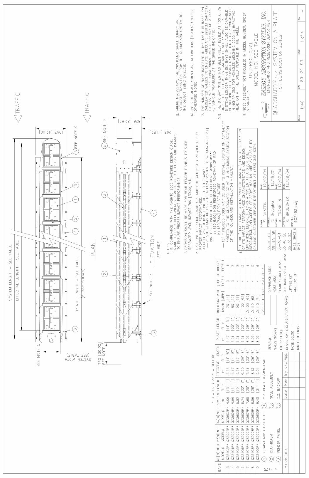
FOR CONTRACT NO.: 05-0T0004
ID NO. 0500000471
INFORMATION HANDOUT
MATERIALS INFORMATION
ABSORB 350 INSTALLATION AND MAINTENANCE MANUAL
ADIEM 350
INSTALLATION AND MAINTENANCE
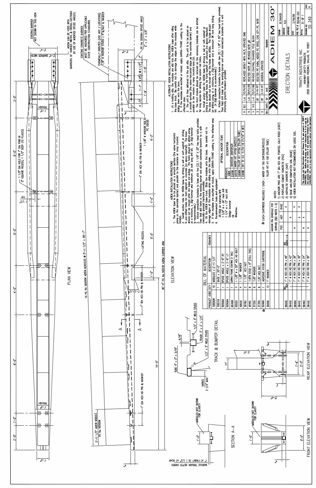
ADIEM 30' ERECTION DETAILS
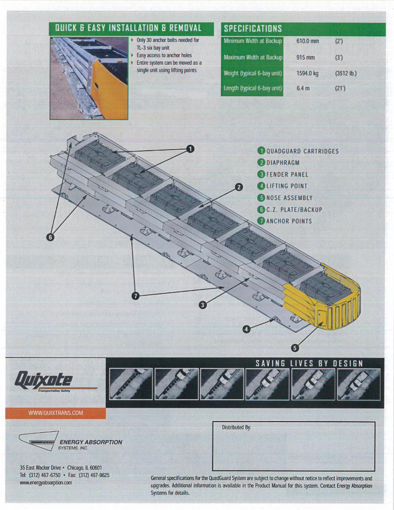
QUADGUARD CZ SYSTEM
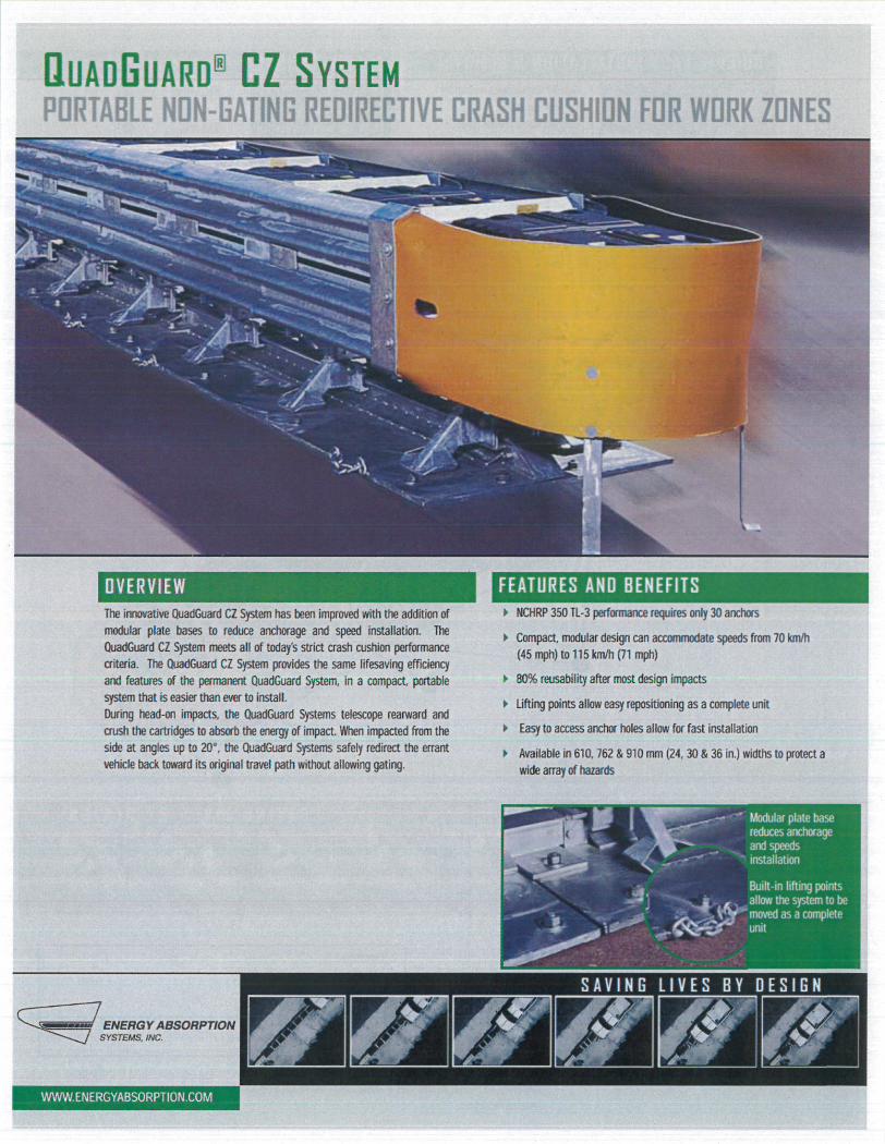
OVERVIEW, FEATURES AND BENEFITS
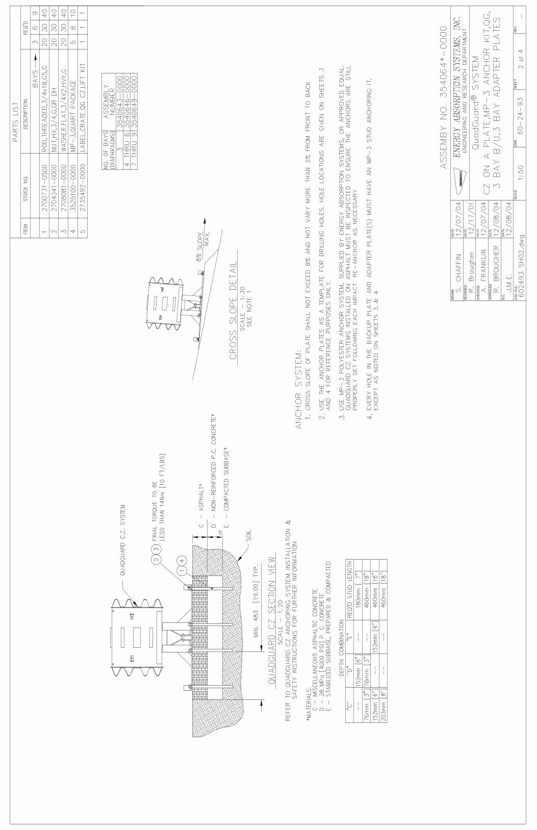
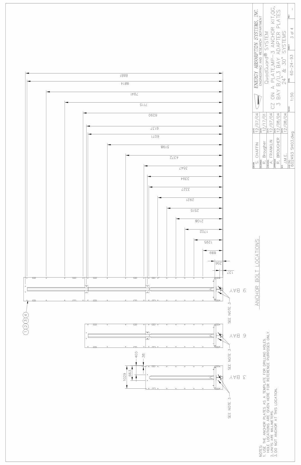
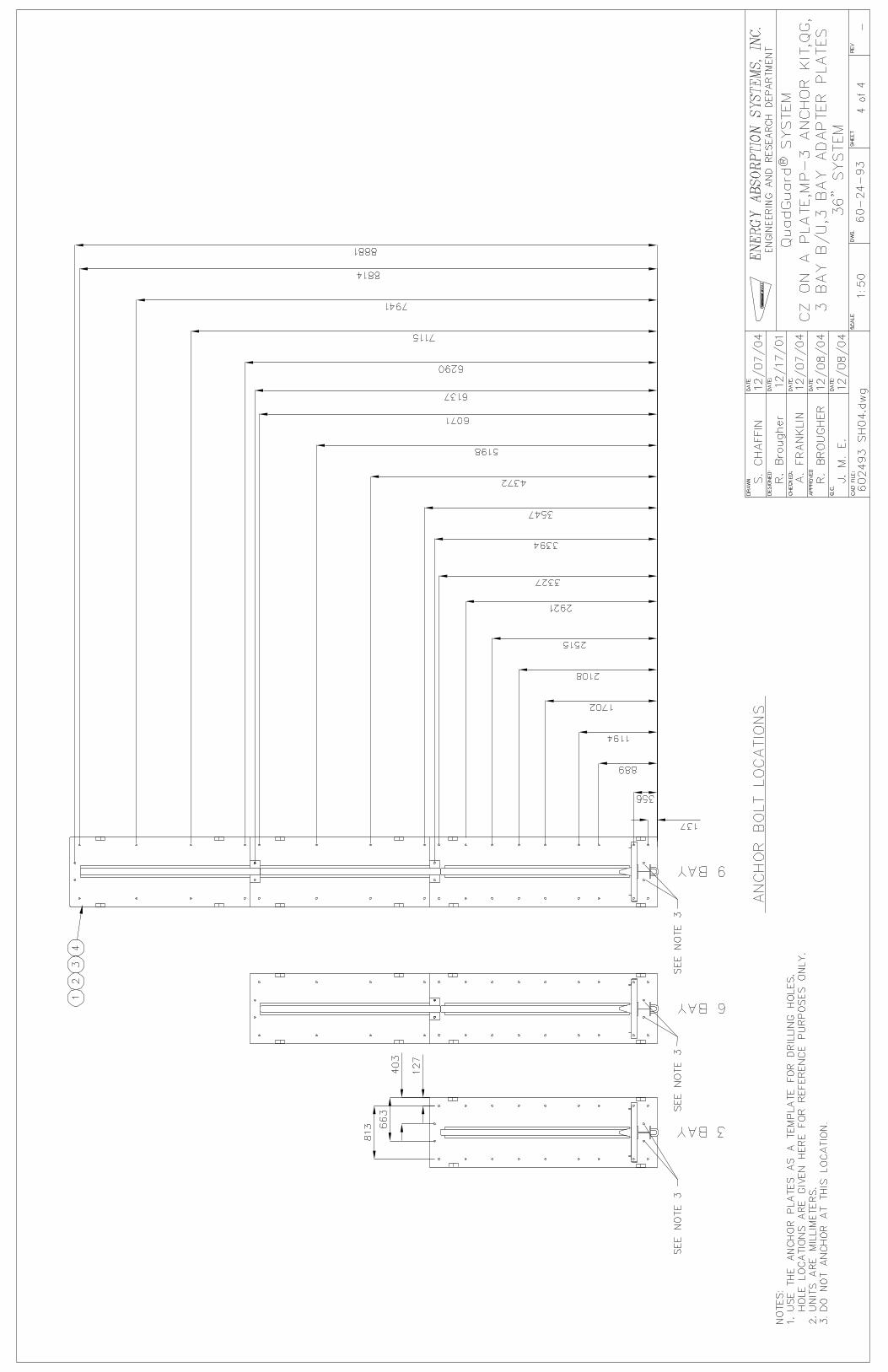
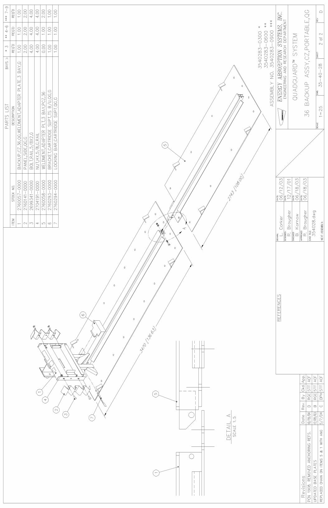
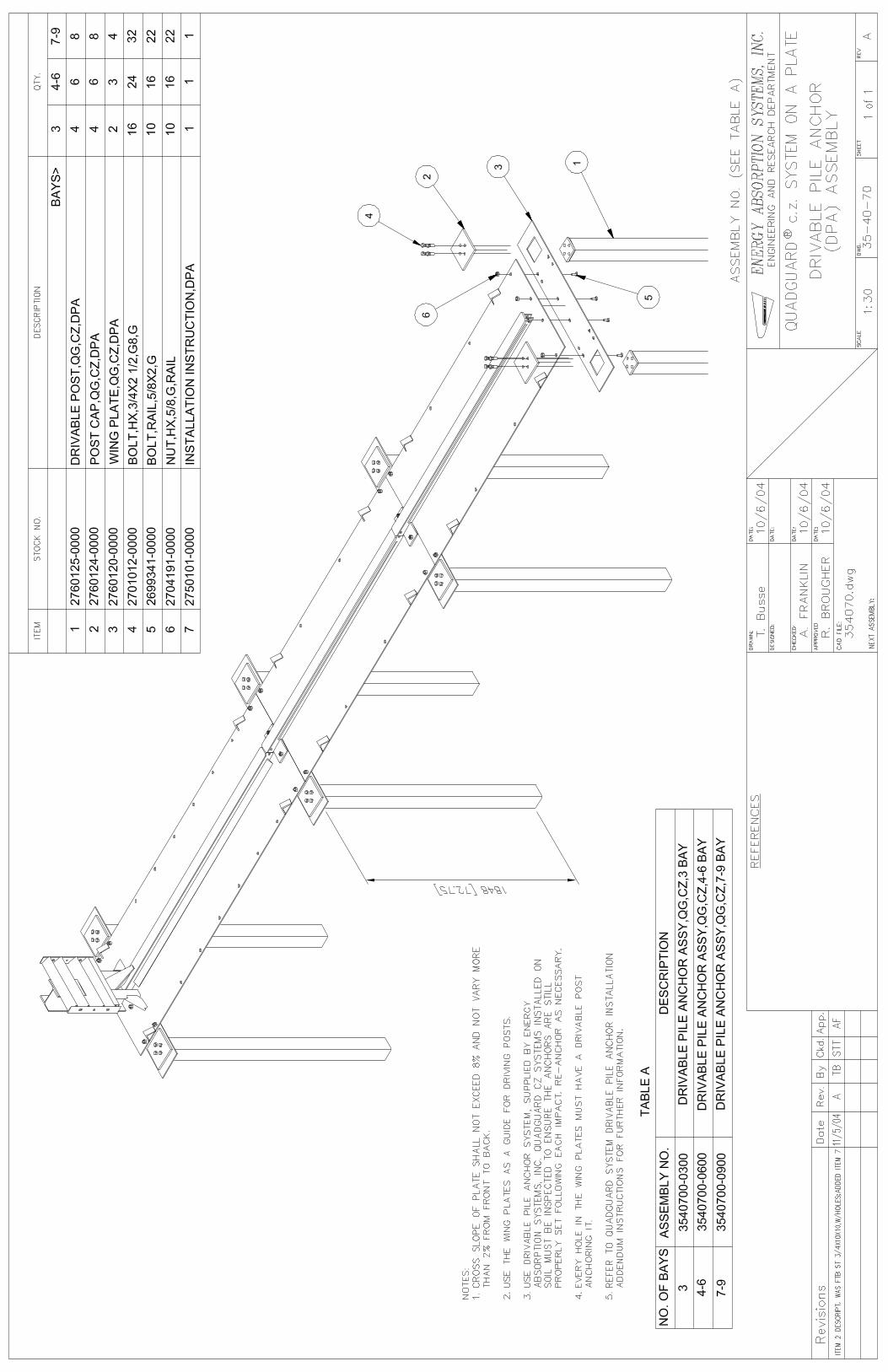
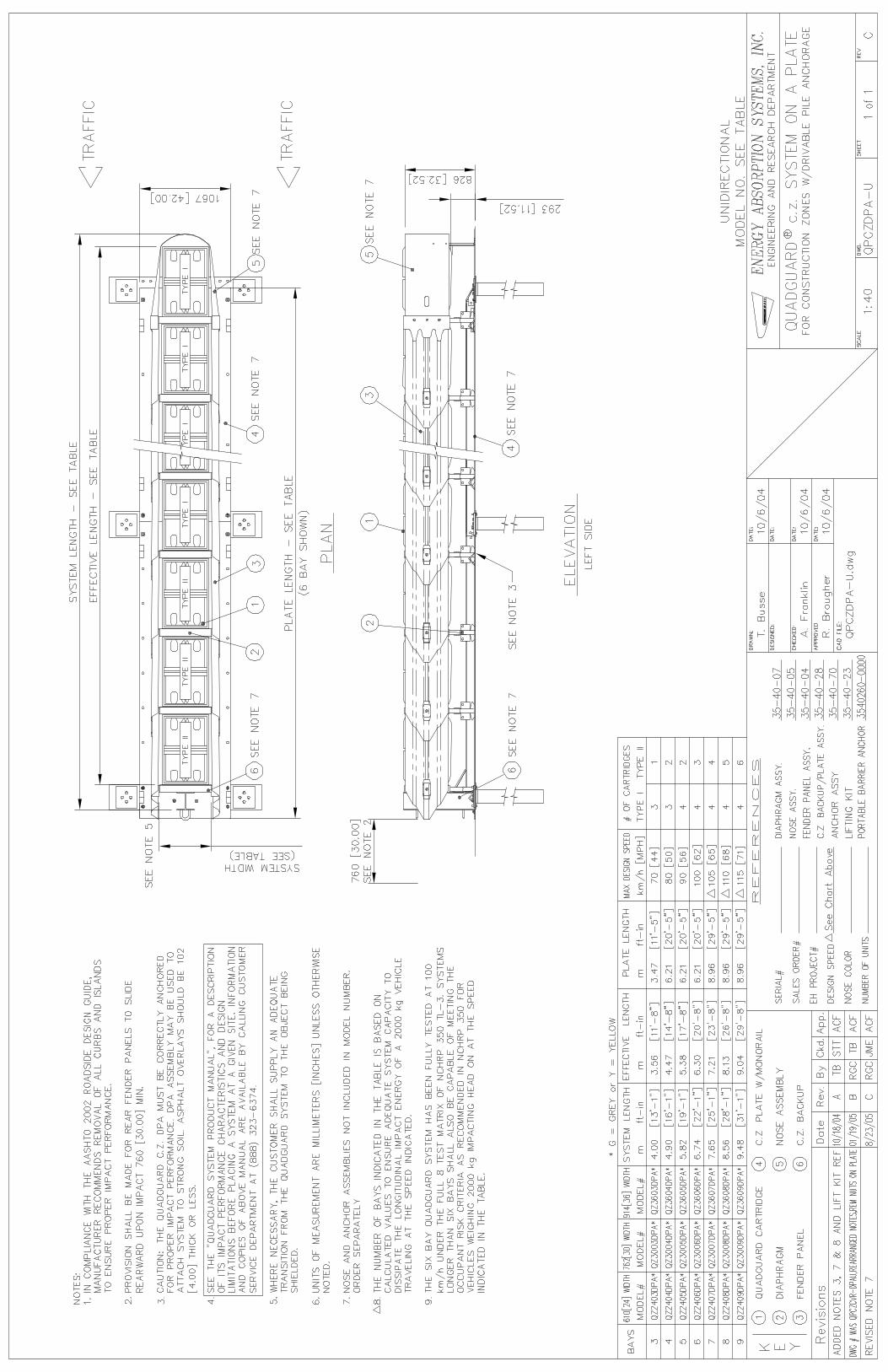
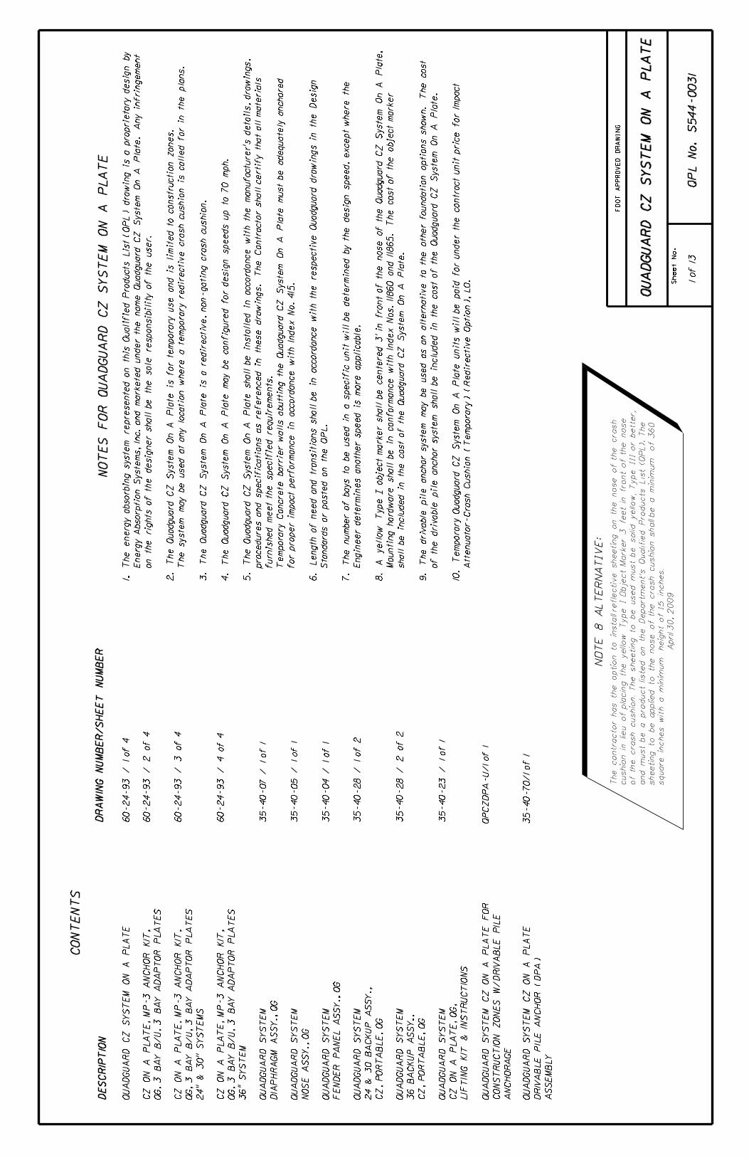
QUADGUARD CZ SYSTEM ON A PLATE DRAWINGS
ROUTE: 05-SB-154-R7.8/R8.3
010912 v8 Page 1
“Advancing Safety Through Innovation”
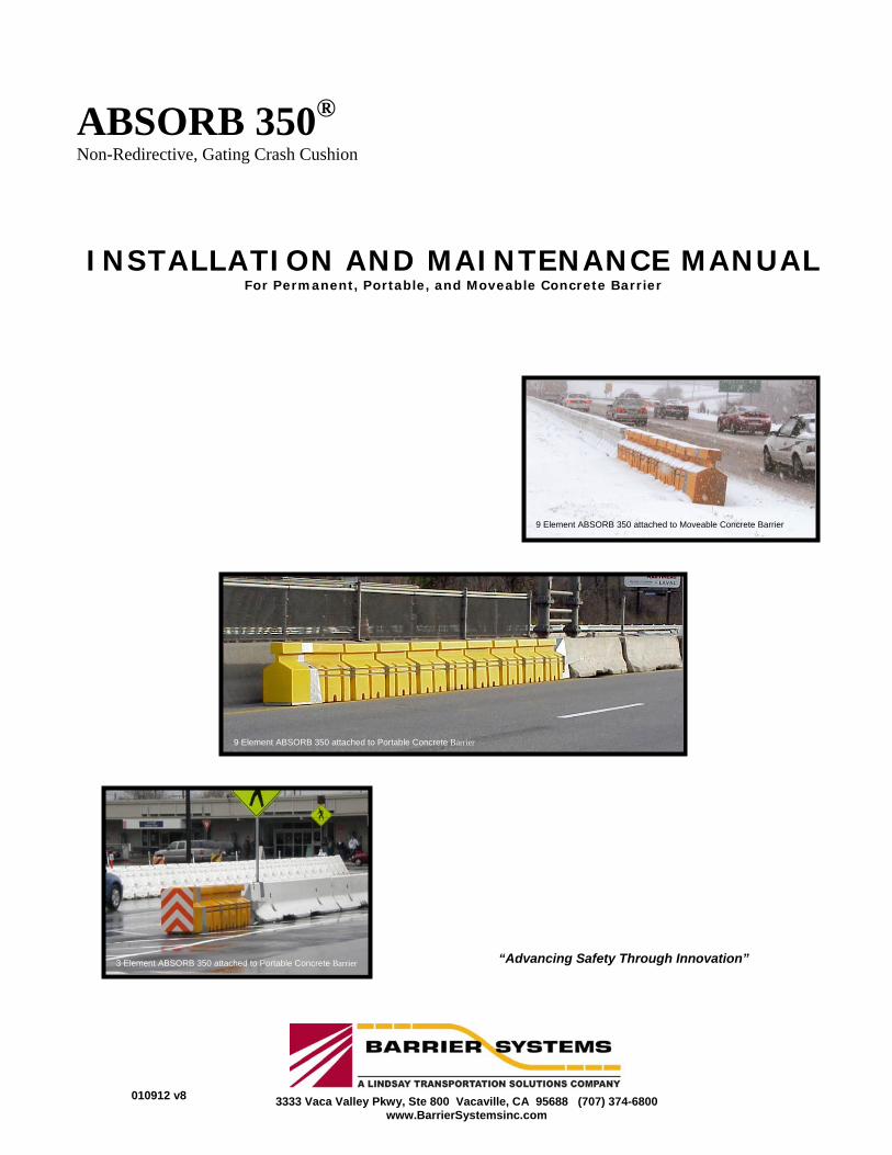
ABSORB 350® Non-Redirective, Gating Crash Cushion
INSTALLATION AND MAINTENANCE MANUAL For Permanent, Portable, and Moveable Concrete Barrier
8 Element ABSORB 350 attached to Moveable Concrete Barrier (QMB)
9 Element ABSORB 350 attached to Moveable Concrete Barrier
9 Element ABSORB 350 attached to Portable Concrete Barrier
3333 Vaca Valley Pkwy, Ste 800 Vacaville, CA 95688 (707) 374-6800 www.BarrierSystemsinc.com
3 Element ABSORB 350 attached to Portable Concrete Barrier
PATENTS PENDING
010912 v8 Page 2
A B S O R B 3 5 0 ® C r a s h C u s h i o n I N S T A L L A T I O N
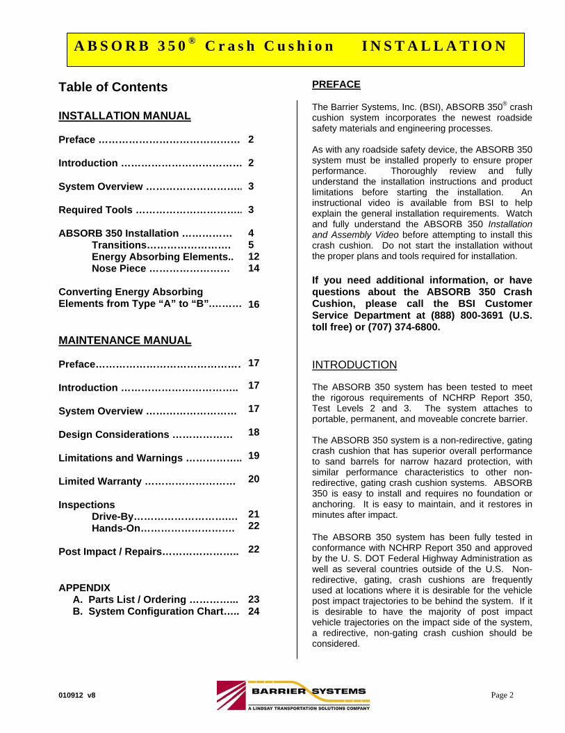
Table of Contents INSTALLATION MANUAL Preface …………………………………… 2 Introduction ……………………………… 2 System Overview ……………………….. 2 Required Tools ………………………….. 3 ABSORB 350 Installation ……………
Transitions……………………. Energy Absorbing Elements.. Nose Piece ……………………
Converting Energy Absorbing Elements from Type “A” to “B”.……… MAINTENANCE MANUAL Preface………………………………………. Introduction …………………………….. System Overview ……………………… Design Considerations ……………… Limitations and Warnings ……………..15 Limited Warranty ……………………… Inspections
Drive-By……………………….… Hands-On……………………….
Post Impact / Repairs………………….. APPENDIX A. Parts List / Ordering …………... B. System Configuration Chart…..
PREFACE The Barrier Systems, Inc. (BSI), ABSORB 350® crash cushion system incorporates the newest roadside safety materials and engineering processes. As with any roadside safety device, the ABSORB 350 system must be installed properly to ensure proper performance. Thoroughly review and fully understand the installation instructions and product limitations before starting the installation. An instructional video is available from BSI to help explain the general installation requirements. Watch and fully understand the ABSORB 350 Installation and Assembly Video before attempting to install this crash cushion. Do not start the installation without the proper plans and tools required for installation. If you need additional information, or have questions about the ABSORB 350 Crash Cushion, please call the BSI Customer Service Department at (888) 800-3691 (U.S. toll free) or (707) 374-6800. INTRODUCTION The ABSORB 350 system has been tested to meet the rigorous requirements of NCHRP Report 350, Test Levels 2 and 3. The system attaches to portable, permanent, and moveable concrete barrier. The ABSORB 350 system is a non-redirective, gating crash cushion that has superior overall performance to sand barrels for narrow hazard protection, with similar performance characteristics to other non-redirective, gating crash cushion systems. ABSORB 350 is easy to install and requires no foundation or anchoring. It is easy to maintain, and it restores in minutes after impact. The ABSORB 350 system has been fully tested in conformance with NCHRP Report 350 and approved by the U. S. DOT Federal Highway Administration as well as several countries outside of the U.S. Non-redirective, gating, crash cushions are frequently used at locations where it is desirable for the vehicle post impact trajectories to be behind the system. If it is desirable to have the majority of post impact vehicle trajectories on the impact side of the system, a redirective, non-gating crash cushion should be considered.
2 2 3 3 4 5 12 14 16 17 17 17 18 19 20 21 22 22
23 24
010912 v8 Page 3
A B S O R B 3 5 0 ® C r a s h C u s h i o n I N S T A L L A T I O N
SYSTEM OVERVIEW
The ABSORB 350 system is designed and constructed to provide acceptable structural adequacy, minimal occupant risk and safe vehicle trajectory as set forth in NCHRP 350 for a Non-Redirective, Gating, Crash Cushion. Individual sections of the system are linked and pinned together to form a continuous freestanding installation (the system is not anchored to the foundation surface). The effective length of each element is 1m and the effective overall height is 800 mm. The effective width of the upright portion of each section is 61 cm. Each section is fabricated out of a roto-molded shell that is filled with water and fitted with steel hardware to allow the sections to be connected. The mass of each section is approximately 50 kg (110 lbs.) empty and 315 kg (695 lbs.) filled. REQUIRED TOOLS ½” (12 mm) drive deep sockets: 19 mm, 24 mm Open / box end wrench: 19mm, 24mm ½” (12 mm) drive ratchet with extensions Rotohammer for drilling holes in concrete: 1/2” (12 mm) X 10” (250 mm) bit Measuring tape Safety equipment: glasses, gloves ½” Air impact wrench (Optional) 3” Hole saw (for drilling second hole in some elements) Round tapered aligning bar Note: The tools list is a general recommendation. Depending on the specific characteristics of the job site, additional tools may be necessary.
BEFORE ABSORB 350 INSTALLATION Placement and use of the ABSORB 350 system should be accomplished in accordance with the guidelines and recommendations set forth in the “AASHTO Roadside Design Guide,” FHWA memoranda and other state and local standards. Depending on the application and circumstances at the job site, installation and assembly should take a two-person crew less than 1 hour. The ABSORB 350 is a highly engineered safety device made up of a relatively small number of parts. Before starting the assembly, become familiar with the basic elements that make up the ABSORB 350 system.
010912 v8 Page 4
A B S O R B 3 5 0 ® C r a s h C u s h i o n I N S T A L L A T I O N
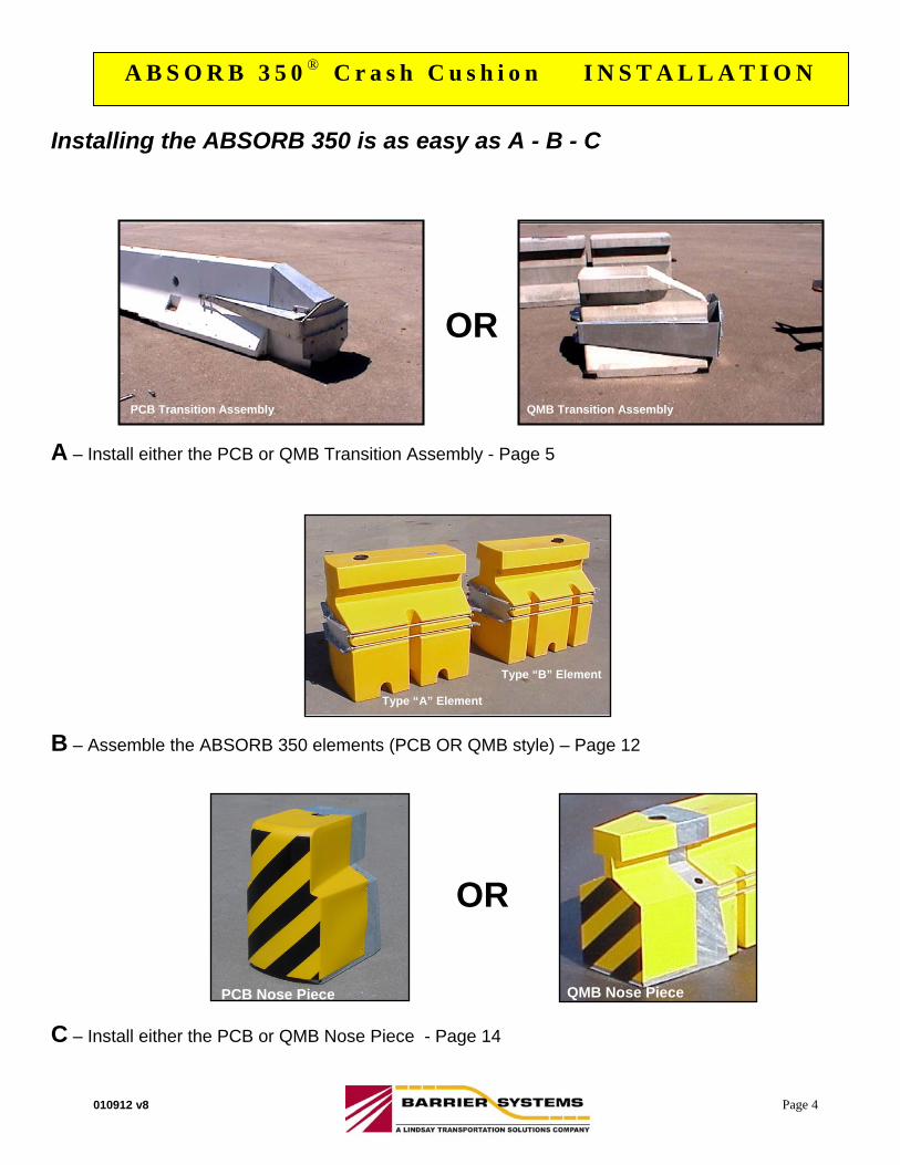
Installing the ABSORB 350 is as easy as A - B - C
A – Install either the PCB or QMB Transition Assembly - Page 5
B – Assemble the ABSORB 350 elements (PCB OR QMB style) – Page 12
C – Install either the PCB or QMB Nose Piece - Page 14
QMB Nose Piece PCB Nose Piece
OR
OR
Type “A” Element
Type “B” Element
PCB Transition Assembly QMB Transition Assembly
PATENTS PENDING
010912 v8 Page 5
A B S O R B 3 5 0 ® C r a s h C u s h i o n I N S T A L L A T I O N
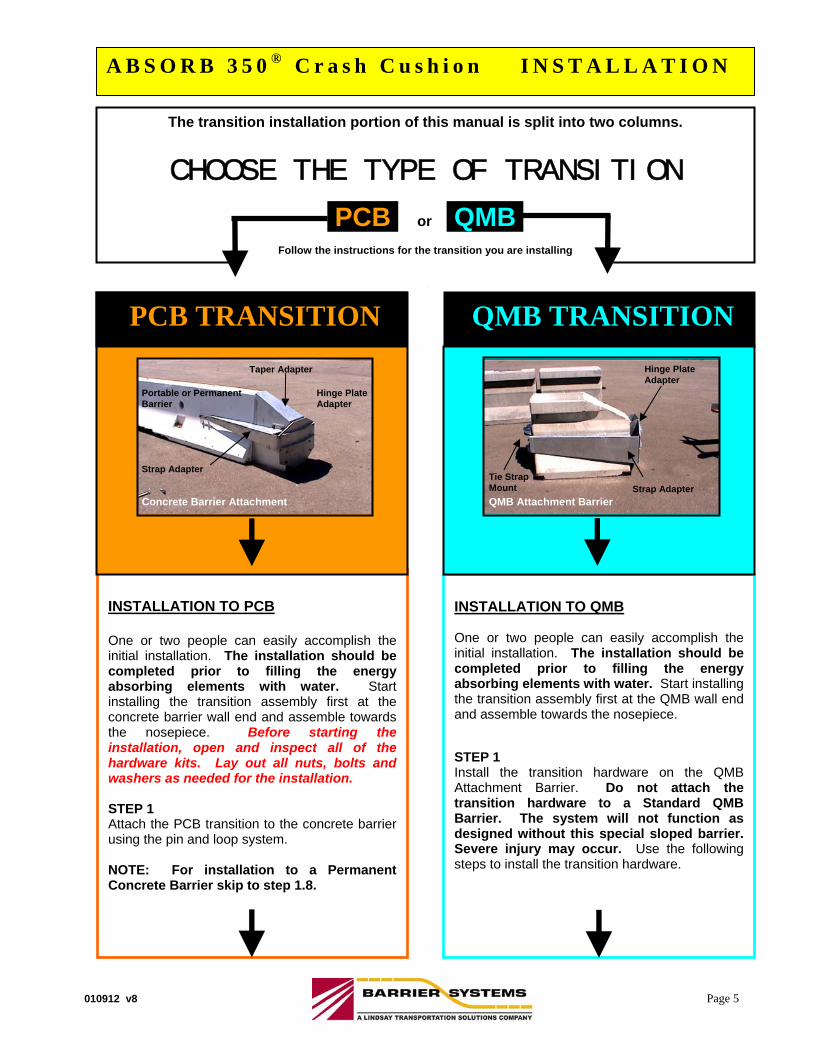
INSTALLATION TO PCB One or two people can easily accomplish the initial installation. The installation should be completed prior to filling the energy absorbing elements with water. Start installing the transition assembly first at the concrete barrier wall end and assemble towards the nosepiece. Before starting the installation, open and inspect all of the hardware kits. Lay out all nuts, bolts and washers as needed for the installation. STEP 1 Attach the PCB transition to the concrete barrier using the pin and loop system. NOTE: For installation to a Permanent Concrete Barrier skip to step 1.8.
The transition installation portion of this manual is split into two columns.
CHOOSE THE TYPE OF TRANSITION
PCB or QMB,
Follow the instructions for the transition you are installing
Hinge Plate Adapter
Portable or Permanent Barrier
Concrete Barrier Attachment
Taper Adapter
Strap Adapter
INSTALLATION TO QMB One or two people can easily accomplish the initial installation. The installation should be completed prior to filling the energy absorbing elements with water. Start installing the transition assembly first at the QMB wall end and assemble towards the nosepiece. STEP 1 Install the transition hardware on the QMB Attachment Barrier. Do not attach the transition hardware to a Standard QMB Barrier. The system will not function as designed without this special sloped barrier. Severe injury may occur. Use the following steps to install the transition hardware.
QMB TRANSITION PCB TRANSITION
QMB Attachment Barrier
Hinge Plate Adapter
Strap Adapter Tie Strap Mount
010912 v8 Page 6
A B S O R B 3 5 0 ® C r a s h C u s h i o n I N S T A L L A T I O N
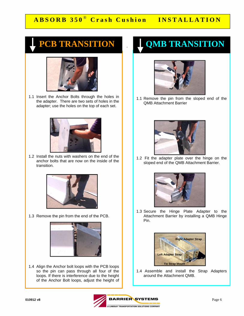
1.1 Remove the pin from the sloped end of the
QMB Attachment Barrier
1.2 Fit the adapter plate over the hinge on the
sloped end of the QMB Attachment Barrier. 1.3 Secure the Hinge Plate Adapter to the
Attachment Barrier by installing a QMB Hinge Pin.
1.4 Assemble and install the Strap Adapters
around the Attachment QMB.
1.1 Insert the Anchor Bolts through the holes in
the adapter. There are two sets of holes in the adapter; use the holes on the top of each set.
1.2 Install the nuts with washers on the end of the
anchor bolts that are now on the inside of the transition.
1.3 Remove the pin from the end of the PCB. 1.4 Align the Anchor bolt loops with the PCB loops
so the pin can pass through all four of the loops. If there is interference due to the height of the Anchor Bolt loops, adjust the height of
QMB TRANSITION PCB TRANSITION
Left Adapter Strap
Tie Strap Mount
Right Adapter Strap
010912 v8 Page 7
A B S O R B 3 5 0 ® C r a s h C u s h i o n I N S T A L L A T I O N
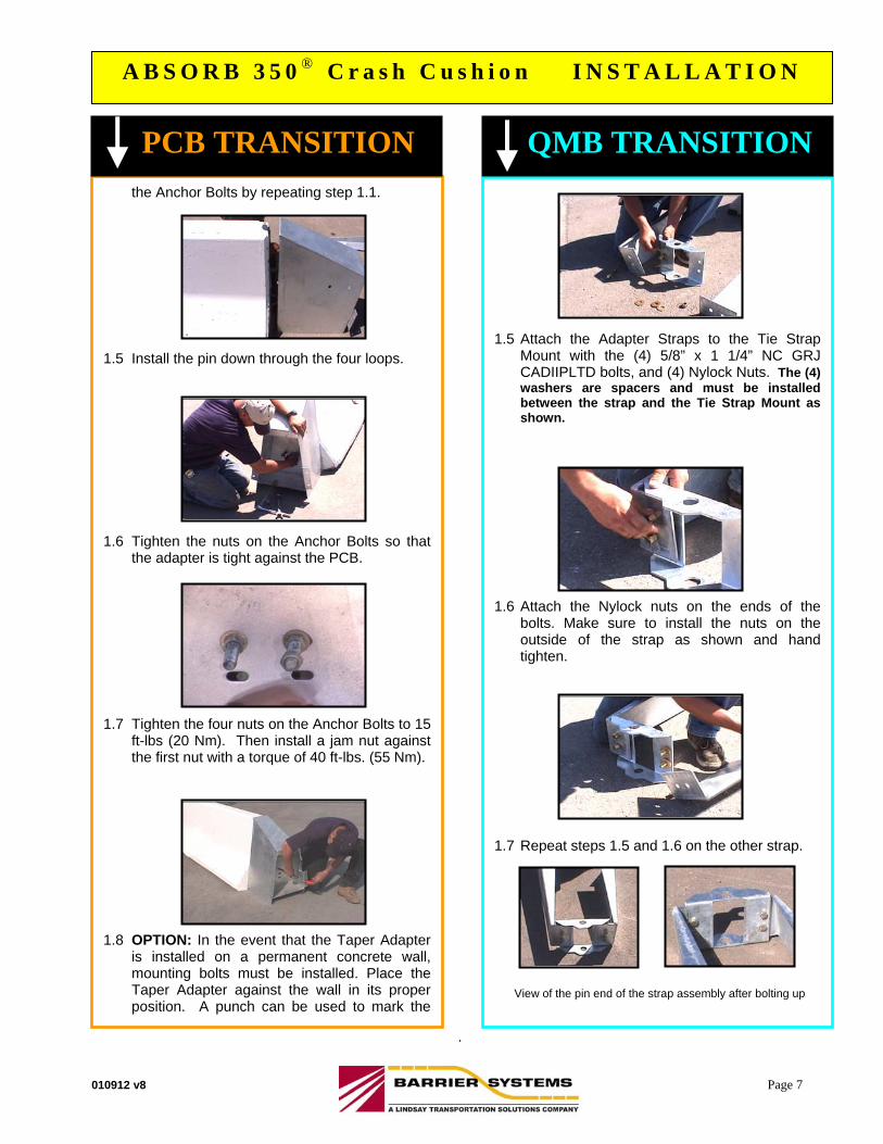
1.5 Attach the Adapter Straps to the Tie Strap
Mount with the (4) 5/8” x 1 1/4” NC GRJ CADIIPLTD bolts, and (4) Nylock Nuts. The (4) washers are spacers and must be installed between the strap and the Tie Strap Mount as shown.
1.6 Attach the Nylock nuts on the ends of the
bolts. Make sure to install the nuts on the outside of the strap as shown and hand tighten.
1.7 Repeat steps 1.5 and 1.6 on the other strap. View of the pin end of the strap assembly after bolting up
the Anchor Bolts by repeating step 1.1. 1.5 Install the pin down through the four loops. 1.6 Tighten the nuts on the Anchor Bolts so that
the adapter is tight against the PCB. 1.7 Tighten the four nuts on the Anchor Bolts to 15
ft-lbs (20 Nm). Then install a jam nut against the first nut with a torque of 40 ft-lbs. (55 Nm).
1.8 OPTION: In the event that the Taper Adapter
is installed on a permanent concrete wall, mounting bolts must be installed. Place the Taper Adapter against the wall in its proper position. A punch can be used to mark the
QMB TRANSITION PCB TRANSITION
010912 v8 Page 8
A B S O R B 3 5 0 ® C r a s h C u s h i o n I N S T A L L A T I O N
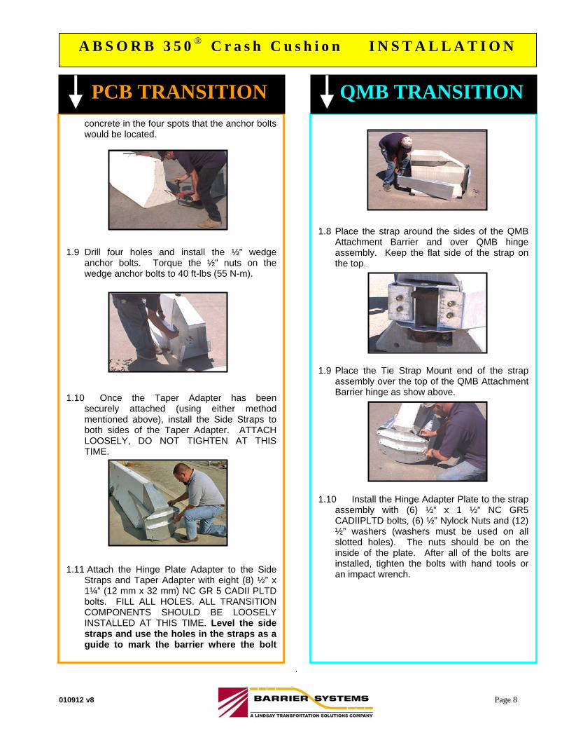
concrete in the four spots that the anchor bolts would be located.
1.9 Drill four holes and install the ½” wedge
anchor bolts. Torque the ½” nuts on the wedge anchor bolts to 40 ft-lbs (55 N-m).
1.10 Once the Taper Adapter has been
securely attached (using either method mentioned above), install the Side Straps to both sides of the Taper Adapter. ATTACH LOOSELY, DO NOT TIGHTEN AT THIS TIME.
1.11 Attach the Hinge Plate Adapter to the Side
Straps and Taper Adapter with eight (8) ½” x 1¼” (12 mm x 32 mm) NC GR 5 CADII PLTD bolts. FILL ALL HOLES. ALL TRANSITION COMPONENTS SHOULD BE LOOSELY INSTALLED AT THIS TIME. Level the side straps and use the holes in the straps as a guide to mark the barrier where the bolt
1.8 Place the strap around the sides of the QMB
Attachment Barrier and over QMB hinge assembly. Keep the flat side of the strap on the top.
1.9 Place the Tie Strap Mount end of the strap
assembly over the top of the QMB Attachment Barrier hinge as show above.
1.10 Install the Hinge Adapter Plate to the strap
assembly with (6) ½” x 1 ½” NC GR5 CADIIPLTD bolts, (6) ½” Nylock Nuts and (12) ½” washers (washers must be used on all slotted holes). The nuts should be on the inside of the plate. After all of the bolts are installed, tighten the bolts with hand tools or an impact wrench.
QMB TRANSITION PCB TRANSITION
010912 v8 Page 9
A B S O R B 3 5 0 ® C r a s h C u s h i o n I N S T A L L A T I O N
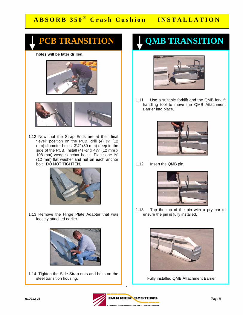
holes will be later drilled. 1.12 Now that the Strap Ends are at their final
“level” position on the PCB, drill (4) ½” (12 mm) diameter holes, 3¼” (80 mm) deep in the side of the PCB. Install (4) ½” x 4¼” (12 mm x 108 mm) wedge anchor bolts. Place one ½” (12 mm) flat washer and nut on each anchor bolt. DO NOT TIGHTEN.
1.13 Remove the Hinge Plate Adapter that was
loosely attached earlier. 1.14 Tighten the Side Strap nuts and bolts on the
steel transition housing.
QMB TRANSITION PCB TRANSITION
1.11 Use a suitable forklift and the QMB forklift
handling tool to move the QMB Attachment Barrier into place.
1.12 Insert the QMB pin. 1.13 Tap the top of the pin with a pry bar to
ensure the pin is fully installed. Fully installed QMB Attachment Barrier
010912 v8 Page 10
A B S O R B 3 5 0 ® C r a s h C u s h i o n I N S T A L L A T I O N
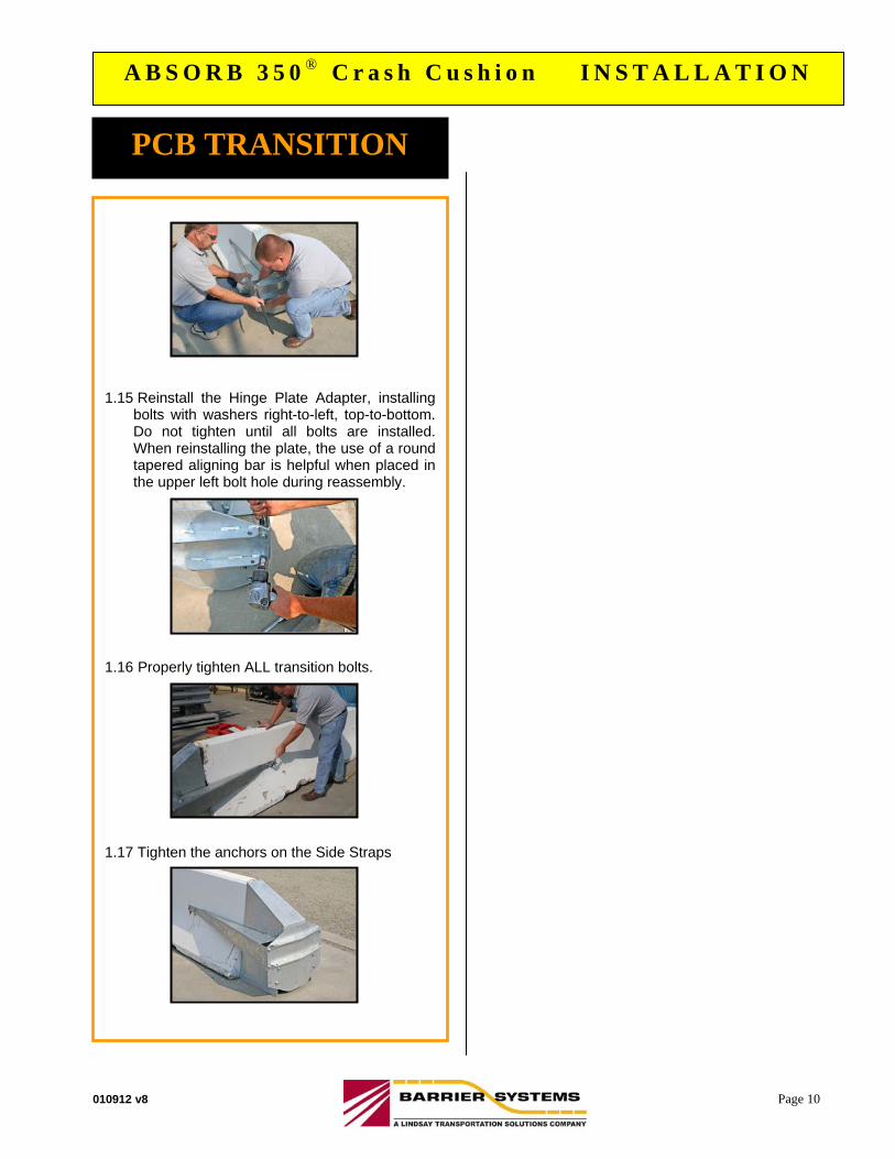
1.15 Reinstall the Hinge Plate Adapter, installing
bolts with washers right-to-left, top-to-bottom. Do not tighten until all bolts are installed. When reinstalling the plate, the use of a round tapered aligning bar is helpful when placed in the upper left bolt hole during reassembly.
1.16 Properly tighten ALL transition bolts. 1.17 Tighten the anchors on the Side Straps
PCB TRANSITION
010912 v8 Page 11
A B S O R B 3 5 0 ® C r a s h C u s h i o n I N S T A L L A T I O N
CAREFULLY CHOOSE THE REQUIRED SYSTEM
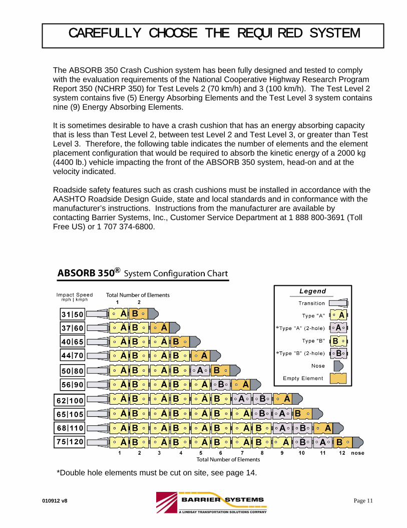
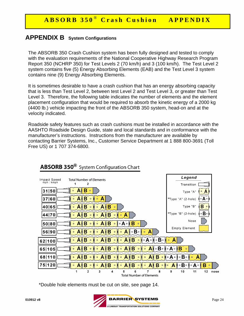
The ABSORB 350 Crash Cushion system has been fully designed and tested to comply with the evaluation requirements of the National Cooperative Highway Research Program Report 350 (NCHRP 350) for Test Levels 2 (70 km/h) and 3 (100 km/h). The Test Level 2 system contains five (5) Energy Absorbing Elements and the Test Level 3 system contains nine (9) Energy Absorbing Elements. It is sometimes desirable to have a crash cushion that has an energy absorbing capacity that is less than Test Level 2, between test Level 2 and Test Level 3, or greater than Test Level 3. Therefore, the following table indicates the number of elements and the element placement configuration that would be required to absorb the kinetic energy of a 2000 kg (4400 lb.) vehicle impacting the front of the ABSORB 350 system, head-on and at the velocity indicated. Roadside safety features such as crash cushions must be installed in accordance with the AASHTO Roadside Design Guide, state and local standards and in conformance with the manufacturer’s instructions. Instructions from the manufacturer are available by contacting Barrier Systems, Inc., Customer Service Department at 1 888 800-3691 (Toll Free US) or 1 707 374-6800.
*Double hole elements must be cut on site, see page 14.
*
*

010912 v8 Page 12
A B S O R B 3 5 0 ® C r a s h C u s h i o n I N S T A L L A T I O N
INSTALL ENERGY ABSORBING ELEMENTS There are two types of Energy Absorbing Elements and each type has a forward and rearward end. The forward end is considered the end that faces the Nose Piece. The rearward end faces the Concrete Barrier wall or QMB wall. The two types of elements are identified by the number of vertical indentations along each side in relation to the front and rear hinges. See a picture of the two different elements on page 4 and a hardware diagram on page 15. When the Absorb 350 system is assembled, it is important to ensure that the two types of elements are ALWAYS ASSEMBLED IN AN ALTERNATING FASHION as shown in System Configuration Chart on Page 11. Thus, when you look down either side of the assembled system, you should see an alternating pattern of vertical indentations (i.e. two, one, two, one, etc.).
STEP 1 Install the first Energy Absorbing Element (Type “A”) to the PCB or QMB Hinge Plate Adapter by inserting the pin on each side of the hinge. Make sure that the harness clip on the pin is installed in the small hole located on the hinge next to the pin.
Install the pin with clip
INSTALLATION INSTRUCTIONS FOR ENERGY ABSORBING ELEMENTS
PCB and QMB
Type “A”
Pin Configuration
010912 v8 Page 13
A B S O R B 3 5 0 ® C r a s h C u s h i o n I N S T A L L A T I O N
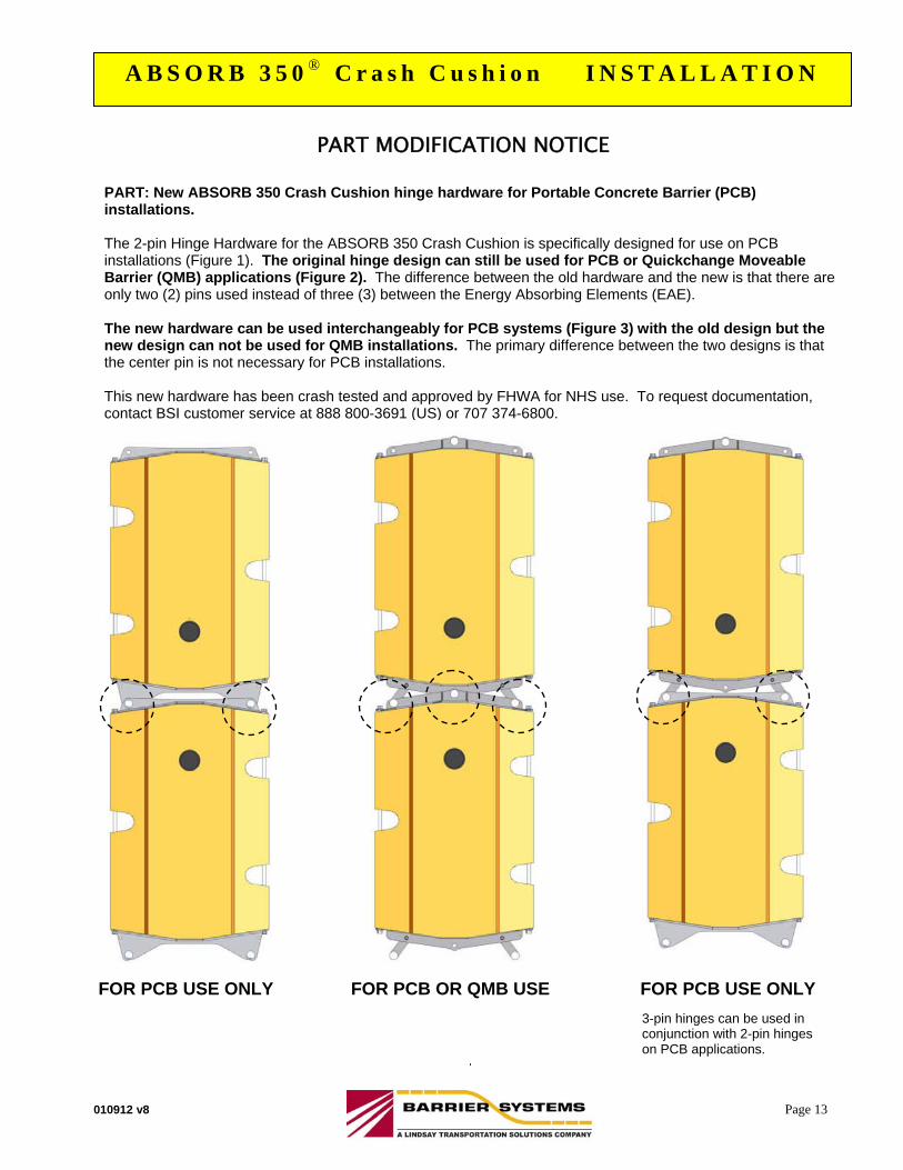
PART MODIFICATION NOTICE PART: New ABSORB 350 Crash Cushion hinge hardware for Portable Concrete Barrier (PCB) installations. The 2-pin Hinge Hardware for the ABSORB 350 Crash Cushion is specifically designed for use on PCB installations (Figure 1). The original hinge design can still be used for PCB or Quickchange Moveable Barrier (QMB) applications (Figure 2). The difference between the old hardware and the new is that there are only two (2) pins used instead of three (3) between the Energy Absorbing Elements (EAE). The new hardware can be used interchangeably for PCB systems (Figure 3) with the old design but the new design can not be used for QMB installations. The primary difference between the two designs is that the center pin is not necessary for PCB installations. This new hardware has been crash tested and approved by FHWA for NHS use. To request documentation, contact BSI customer service at 888 800-3691 (US) or 707 374-6800.
FOR PCB USE ONLY
FOR PCB OR QMB USE FOR PCB USE ONLY
3-pin hinges can be used in conjunction with 2-pin hinges on PCB applications.
PATENTS PENDING
010912 v8 Page 14
A B S O R B 3 5 0 ® C r a s h C u s h i o n I N S T A L L A T I O N
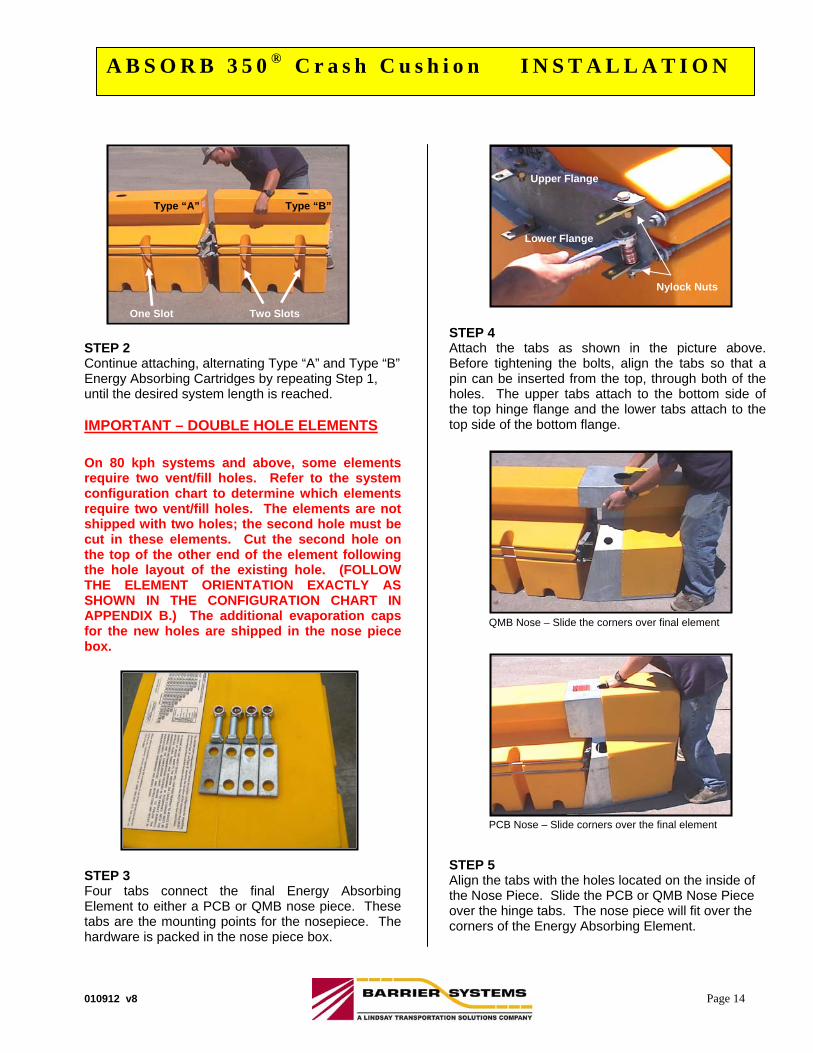
STEP 2 Continue attaching, alternating Type “A” and Type “B” Energy Absorbing Cartridges by repeating Step 1, until the desired system length is reached. IMPORTANT – DOUBLE HOLE ELEMENTS
On 80 kph systems and above, some elements require two vent/fill holes. Refer to the system configuration chart to determine which elements require two vent/fill holes. The elements are not shipped with two holes; the second hole must be cut in these elements. Cut the second hole on the top of the other end of the element following the hole layout of the existing hole. (FOLLOW THE ELEMENT ORIENTATION EXACTLY AS SHOWN IN THE CONFIGURATION CHART IN APPENDIX B.) The additional evaporation caps for the new holes are shipped in the nose piece box. STEP 3 Four tabs connect the final Energy Absorbing Element to either a PCB or QMB nose piece. These tabs are the mounting points for the nosepiece. The hardware is packed in the nose piece box.
STEP 4 Attach the tabs as shown in the picture above. Before tightening the bolts, align the tabs so that a pin can be inserted from the top, through both of the holes. The upper tabs attach to the bottom side of the top hinge flange and the lower tabs attach to the top side of the bottom flange.
STEP 5 Align the tabs with the holes located on the inside of the Nose Piece. Slide the PCB or QMB Nose Piece over the hinge tabs. The nose piece will fit over the corners of the Energy Absorbing Element.
Type “A” Type “B”
One Slot Two Slots
Nylock Nuts
Upper Flange
Lower Flange
QMB Nose – Slide the corners over final element
PCB Nose – Slide corners over the final element
010912 v8 Page 15
A B S O R B 3 5 0 ® C r a s h C u s h i o n I N S T A L L A T I O N
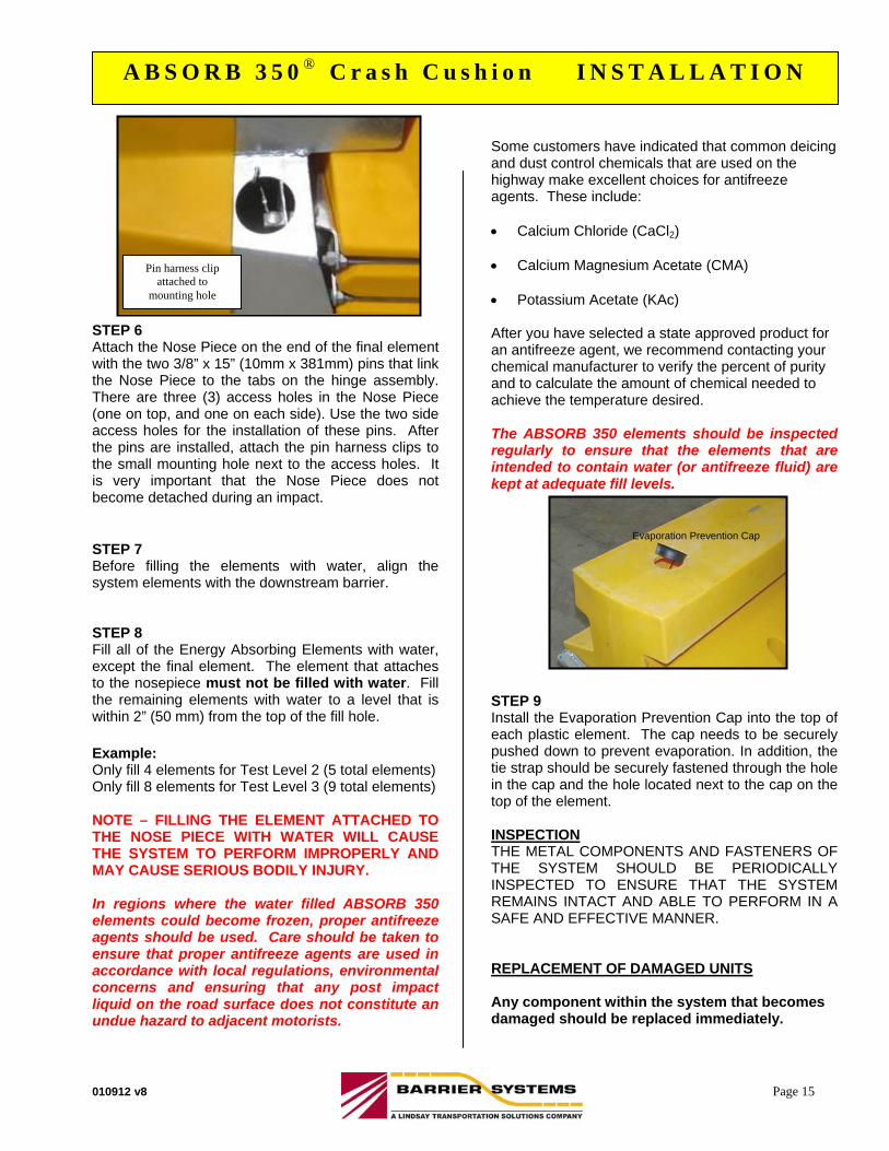
STEP 6 Attach the Nose Piece on the end of the final element with the two 3/8” x 15” (10mm x 381mm) pins that link the Nose Piece to the tabs on the hinge assembly. There are three (3) access holes in the Nose Piece (one on top, and one on each side). Use the two side access holes for the installation of these pins. After the pins are installed, attach the pin harness clips to the small mounting hole next to the access holes. It is very important that the Nose Piece does not become detached during an impact. STEP 7 Before filling the elements with water, align the system elements with the downstream barrier. STEP 8 Fill all of the Energy Absorbing Elements with water, except the final element. The element that attaches to the nosepiece must not be filled with water. Fill the remaining elements with water to a level that is within 2” (50 mm) from the top of the fill hole. Example: Only fill 4 elements for Test Level 2 (5 total elements) Only fill 8 elements for Test Level 3 (9 total elements)
NOTE – FILLING THE ELEMENT ATTACHED TO THE NOSE PIECE WITH WATER WILL CAUSE THE SYSTEM TO PERFORM IMPROPERLY AND MAY CAUSE SERIOUS BODILY INJURY.
In regions where the water filled ABSORB 350 elements could become frozen, proper antifreeze agents should be used. Care should be taken to ensure that proper antifreeze agents are used in accordance with local regulations, environmental concerns and ensuring that any post impact liquid on the road surface does not constitute an undue hazard to adjacent motorists.
Some customers have indicated that common deicing and dust control chemicals that are used on the highway make excellent choices for antifreeze agents. These include: Calcium Chloride (CaCl2) Calcium Magnesium Acetate (CMA) Potassium Acetate (KAc) After you have selected a state approved product for an antifreeze agent, we recommend contacting your chemical manufacturer to verify the percent of purity and to calculate the amount of chemical needed to achieve the temperature desired. The ABSORB 350 elements should be inspected regularly to ensure that the elements that are intended to contain water (or antifreeze fluid) are kept at adequate fill levels. STEP 9 Install the Evaporation Prevention Cap into the top of each plastic element. The cap needs to be securely pushed down to prevent evaporation. In addition, the tie strap should be securely fastened through the hole in the cap and the hole located next to the cap on the top of the element. INSPECTION THE METAL COMPONENTS AND FASTENERS OF THE SYSTEM SHOULD BE PERIODICALLY INSPECTED TO ENSURE THAT THE SYSTEM REMAINS INTACT AND ABLE TO PERFORM IN A SAFE AND EFFECTIVE MANNER. REPLACEMENT OF DAMAGED UNITS Any component within the system that becomes damaged should be replaced immediately.
Evaporation Prevention Cap
Pin harness clip attached to
mounting hole
010912 v8 Page 16
A B S O R B 3 5 0 ® C r a s h C u s h i o n I N S T A L L A T I O N
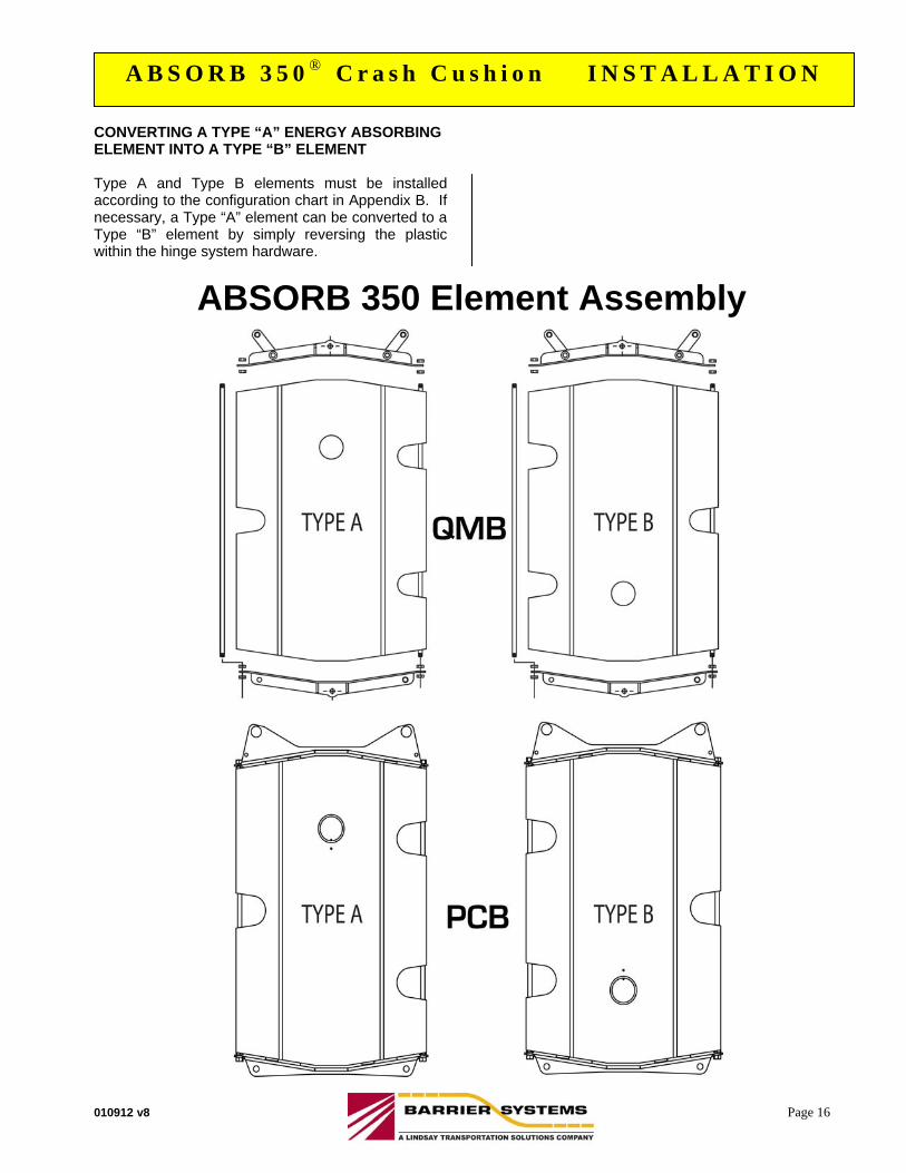
CONVERTING A TYPE “A” ENERGY ABSORBING ELEMENT INTO A TYPE “B” ELEMENT Type A and Type B elements must be installed according to the configuration chart in Appendix B. If necessary, a Type “A” element can be converted to a Type “B” element by simply reversing the plastic within the hinge system hardware.
ABSORB 350 Element Assembly
010912 v8 Page 17
A B S O R B 3 5 0 ® C r a s h C u s h i o n I N S T A L L A T I O NA B S O R B 3 5 0 ® C r a s h C u s h i o n M A I N T E N A N C E
PREFACE The Barrier Systems, Inc. (BSI), ABSORB 350 crash cushion system incorporates the newest roadside safety materials and engineering processes. As with any roadside safety device, the ABSORB 350 system must be properly maintained to insure proper performance. Thoroughly review and fully understand the maintenance instructions and product limitations before performing any maintenance. An instructional video is available from BSI to help explain the general requirements. Do not begin any maintenance operation without the proper plans and tools. For further guidance, refer to the ABSORB 350 Installation portion of this manual. If you need additional information, or have questions about the ABSORB 350 Crash Cushion, please call the BSI Customer Service Department at (888) 800-3691 (U.S. toll free) or (707) 374-6800. INTRODUCTION The ABSORB 350 system has been tested to meet the rigorous requirements of NCHRP Report 350, Test Levels 2 and 3. The systems will be provided in lengths and capacities for both low speed and high speed applications. The ABSORB 350 system is a non-redirective, gating, crash cushion, and is ideally suited for narrow hazards such as portable, permanent or moveable concrete barrier. Ease of installation, numerous transition options, low maintenance requirements, and reusability of system components make the ABSORB 350 system ideal for treating many roadside hazards. Non-Redirective, gating, crash cushions are highway safety devices whose primary function is to improve the safety for occupants of errant vehicles that impact the end of rigid or semi-rigid barriers or fixed roadside hazards by absorbing the inertia of vehicle impact or by allowing controlled penetration of the vehicle. These devices are designed to safely decelerate errant vehicles. These types of systems are typically
applied to locations where head-on and angled impacts are likely to occur and it is not necessarily desirable to have post impact trajectories on the impact side of the system. Placement and use of the ABSORB 350 system should be accomplished in accordance with the guidelines and recommendations set forth in the “AASHTO Roadside Design Guide,” FHWA memoranda and other state and local standards. IMPORTANT INFORMATION The ABSORB 350 crash cushion must be installed properly to maximize the systems ability to protect errant motorists that impact the system. Designers, installers and people that maintain the system should thoroughly understand the manufacturer’s instructions prior to performing any necessary maintenance or repair work. Key information is provided in this Maintenance Manual and important additional information is in the Installation Manual. If these documents are not available, or if there are any questions regarding the proper placement or installation of the ABSORB 350 crash cushion, contact Barrier Systems, Inc., Customer Service at U.S. toll free (888) 800-3691 or (707) 374-6800. SYSTEM OVERVIEW
The ABSORB 350 system is designed and constructed to provide acceptable structural adequacy, minimal occupant risk and safe vehicle trajectory as set forth in NCHRP 350 for non-redirective, gating, crash cushions. The ABSORB 350 system is designed to shield the ends of median barriers and other narrow fixed objects likely to be struck head-on, by absorbing and dissipating the inertia of impacting vehicles. ABSORB 350 utilizes disposable water filled Energy Absorbing Elements (EAEs) to absorb the inertia of the impacting vehicle. Only the Energy Absorbing Elements are expended after most head-on impacts.
PATENTS PENDING
010912 v8 Page 18
A B S O R B 3 5 0 ® C r a s h C u s h i o n I N S T A L L A T I O NA B S O R B 3 5 0 ® C r a s h C u s h i o n M A I N T E N A N C E
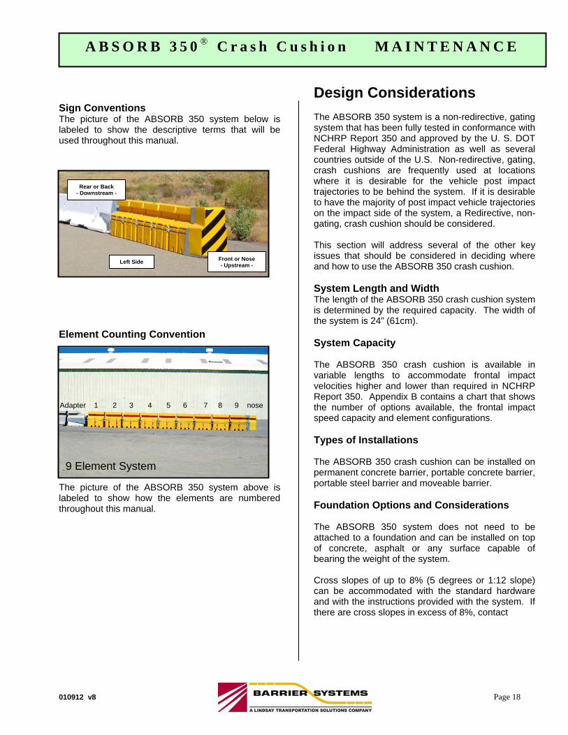
Sign Conventions The picture of the ABSORB 350 system below is labeled to show the descriptive terms that will be used throughout this manual.
Element Counting Convention The picture of the ABSORB 350 system above is labeled to show how the elements are numbered throughout this manual.
Design Considerations The ABSORB 350 system is a non-redirective, gating system that has been fully tested in conformance with NCHRP Report 350 and approved by the U. S. DOT Federal Highway Administration as well as several countries outside of the U.S. Non-redirective, gating, crash cushions are frequently used at locations where it is desirable for the vehicle post impact trajectories to be behind the system. If it is desirable to have the majority of post impact vehicle trajectories on the impact side of the system, a Redirective, non-gating, crash cushion should be considered. This section will address several of the other key issues that should be considered in deciding where and how to use the ABSORB 350 crash cushion. System Length and Width The length of the ABSORB 350 crash cushion system is determined by the required capacity. The width of the system is 24” (61cm). System Capacity The ABSORB 350 crash cushion is available in variable lengths to accommodate frontal impact velocities higher and lower than required in NCHRP Report 350. Appendix B contains a chart that shows the number of options available, the frontal impact speed capacity and element configurations. Types of Installations The ABSORB 350 crash cushion can be installed on permanent concrete barrier, portable concrete barrier, portable steel barrier and moveable barrier. Foundation Options and Considerations The ABSORB 350 system does not need to be attached to a foundation and can be installed on top of concrete, asphalt or any surface capable of bearing the weight of the system. Cross slopes of up to 8% (5 degrees or 1:12 slope) can be accommodated with the standard hardware and with the instructions provided with the system. If there are cross slopes in excess of 8%, contact
Rear or Back - Downstream -
Front or Nose- Upstream -
Left Side
9 Element System
Adapter 1 2 3 4 5 6 7 8 9 nose
010912 v8 Page 19
A B S O R B 3 5 0 ® C r a s h C u s h i o n I N S T A L L A T I O NA B S O R B 3 5 0 ® C r a s h C u s h i o n M A I N T E N A N C E
Barrier Systems, Inc., Customer Service to obtain engineering advice and assistance. Transition Advisory The ABSORB 350 crash cushion was designed to be able to used with permanent, portable, or moveable concrete barrier and portable steel barrier. Special care should be taken to ensure that the type of transition system chosen properly addresses the direction of all vehicles that will be exposed to the system. Other Site Conditions and Considerations There are numerous other conditions that should be taken into consideration when selecting and locating crash cushions. The majority of these are addressed in the “AASHTO Roadside Design Guide” and in memoranda from the Federal Highway Administration and state Departments of Transportation. These should always be taken into consideration when selecting and locating crash cushions. A few of the typical considerations are as follows:
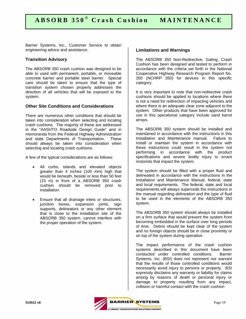
All curbs, islands and elevated objects greater than 4 inches (100 mm) high that would be beneath, beside or less than 50 feet (15 m) in front of a ABSORB 350 crash cushion should be removed prior to installation.
Ensure that all drainage inlets or structures,
junction boxes, expansion joints, sign supports, delineators or any other element that is close to the installation site of the ABSORB 350 system, cannot interfere with the proper operation of the system.
Limitations and Warnings
The ABSORB 350 Non-Redirective, Gating, Crash Cushion has been designed and tested to perform in accordance with the criteria set forth in the National Cooperative Highway Research Program Report No. 350 (NCHRP 350) for devices in this specific category. It is very important to note that non-redirective crash cushions should be applied to locations where there is not a need for redirection of impacting vehicles and where there is an adequate clear zone adjacent to the system. Other products that have been approved for use in this operational category include sand barrel arrays. The ABSORB 350 system should be installed and maintained in accordance with the instructions in this Installation and Maintenance manual. Failure to install or maintain the system in accordance with these instructions could result in the system not performing in accordance with the product specifications and severe bodily injury to errant motorists that impact the system. The system should be filled with a proper fluid and delineated in accordance with the instructions in the Installation and Maintenance Manual, federal, state and local requirements. The federal, state and local requirements will always supercede the instructions in the manual regarding delineation and the type of fluid to be used in the elements of the ABSORB 350 system. The ABSORB 350 system should always be installed on a firm surface that would prevent the system from becoming embedded in the surface over long periods of time. Debris should be kept clear of the system and no foreign objects should be in close proximity or on top of the system during operation. The impact performance of the crash cushion systems described in this document have been conducted under controlled conditions. Barrier Systems, Inc. (BSI) does not represent nor warrant that the results of those controlled conditions would necessarily avoid injury to persons or property. BSI expressly disclaims any warranty or liability for claims arising by reasons of death or personal injury or damage to property resulting from any impact, collision or harmful contact with the crash cushion
010912 v8 Page 20
A B S O R B 3 5 0 ® C r a s h C u s h i o n I N S T A L L A T I O NA B S O R B 3 5 0 ® C r a s h C u s h i o n M A I N T E N A N C E
system or nearby hazards or objects, by any vehicle, objects or persons. LIMITED WARRANTY Barrier Systems, Inc. (BSI) has tested the impact performance of its moveable barrier and crash cushion systems under controlled conditions, however, BSI does not represent nor warrant that the results of those controlled conditions would necessarily avoid injury to persons or property. BSI EXPRESSLY DISCLAIMS ANY WARRANTY OR LIABILITY FOR CLAIMS ARISING BY REASONS OF DEATH OR PERSONAL INJURY OR DAMAGE TO PROPERTY RESULTING FROM ANY IMPACT, COLLISION OR HARMFUL CONTACT WITH THE PRODUCTS OR NEARBY HAZARDS OR OBJECTS BY ANY VEHICLE, OBJECTS OR PERSONS. BSI warrants that any product or component part manufactured by BSI will be free from defects in material or workmanship. BSI will replace free of cost any Product or component part manufactured by BSI that contains such a defect. THE FOREGOING WARRANTY IS IN LIEU OF AND EXCLUDES ALL OTHER WARRANTIES NOT EXPRESSLY SET FORTH HEREIN, WHETHER EXPRESSED OR IMPLIED BY OPERATION OF LAW OR OTHERWISE, INCLUDING BUT NOT LIMITED TO ANY IMPLIED WARRANTIES OF MERCHANTABILITY OR FITNESS FOR A PARTICULAR PURPOSE.
BSI’S LIABILITY UNDER THIS WARRANTY IS EXPRESSLY LIMITED TO REPLACE FREE OF COST (IN THE FORM AND UNDER THE TERMS ORIGINALLY SHIPPED), OR TO REPAIR OR TO MANUFACTURE BY BSI, PRODUCTS OR PARTS NOT COMPLYING WITH BSI SPECIFICATIONS, OR, AT BSI’S ELECTION, TO THE REPAYMENT OF AN AMOUNT EQUAL TO THE PURCHASE PRICE OF SUCH PRODUCTS OR PARTS, WHETHER SUCH CLAIMS ARE FOR BREACH OF WARRANTY OR NEGLIGENCE. BSI SHALL NOT BE LIABLE FOR ANY INCIDENTAL, CONSEQUENTIAL OR SPECIAL LOSSES, DAMAGES OR EXPENSES OF ANY KIND, INCLUDING, WITHOUT LIMITATION, ANY SUCH LOSSES, DAMAGES OR EXPENSES ARISING DIRECTLY OR INDIRECTLY FROM THE SALE, HANDLING OR USE OF THE PRODUCTS FROM ANY OTHER CAUSE RELATING THERETO,
OR FROM PERSONAL INJURY OR LOSS OF PROFIT. Any claim by the Buyer with reference to products sold hereunder for any cause shall be deemed waived by the Buyer unless BSI is notified in writing, in the case of defects apparent on visual inspection, within ninety (90) days from the delivery date, or, in the case of defects not apparent on visual inspection, within twelve (12) months from the said delivery date. Products claimed to be defective may be returned prepaid to BSI’s plant for inspection in accordance with return shipping instructions that BSI shall furnish to the Buyer forthwith upon receipt of the Buyer’s notice of claim. If the claim is established, BSI will reimburse that Buyer for all carriage costs incurred hereunder. The forgoing warranty benefits shall not apply to (i) any Products that have been subject to improper storage, accident, misuse or unauthorized alterations, or that have not been installed, operated, and maintained in accordance with approved procedures and (ii) any components manufactured by the Buyer. For additional information regarding this product, please contact: Barrier Systems, Inc. Customer Support 3333 Vaca Valley Pkwy, Ste 800 Vacaville, CA 95688 U.S. Toll Free (888) 800-3691 Phone: (707) 374-6800 Fax: (707) 374-6801 www.barriersystemsinc.com
010912 v8 Page 21
A B S O R B 3 5 0 ® C r a s h C u s h i o n I N S T A L L A T I O N
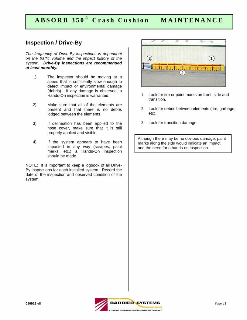
Inspection / Drive-By The frequency of Drive-By inspections is dependent on the traffic volume and the impact history of the system. Drive-By inspections are recommended at least monthly.
1) The inspector should be moving at a speed that is sufficiently slow enough to detect impact or environmental damage (debris). If any damage is observed, a Hands-On inspection is warranted.
2) Make sure that all of the elements are
present and that there is no debris lodged between the elements.
3) If delineation has been applied to the
nose cover, make sure that it is still properly applied and visible.
4) If the system appears to have been
impacted in any way (scrapes, paint marks, etc.) a Hands-On inspection should be made.
NOTE: It is important to keep a logbook of all Drive-By inspections for each installed system. Record the date of the inspection and observed condition of the system.
Although there may be no obvious damage, paint marks along the side would indicate an impact and the need for a hands-on inspection.
1. Look for tire or paint marks on front, side and transition.
2. Look for debris between elements (tire, garbage,
etc).
3. Look for transition damage.
A B S O R B 3 5 0 ® C r a s h C u s h i o n M A I N T E N A N C E
1 3
2
010912 v8 Page 22
A B S O R B 3 5 0 ® C r a s h C u s h i o n I N S T A L L A T I O N
Inspection / Hands-On The frequency of Hands-On inspections is dependant on the traffic volume and the impact history of the system. Hands-On inspections are recommended at least yearly.
1) Check that all of the elements are straight.
2) Check in the spaces between the Energy
Absorbing Elements (EAEs) to remove any debris that may have accumulated.
3) Check the water level in the elements.
The water should be within 2” of the top of the element. THERE SHOULD BE NO WATER IN THE ELEMENT ATTACHED TO THE NOSE PIECE.
4) Check the condition of and the placement
of all Energy Absorbing Elements. Replace any damaged Cartridges. Refer to the chart in Appendix “B” for proper placement.
NOTE: It is important to keep a log book of all Hands-On inspections for each installed system. Record the date of inspection, the observed condition of the system and any replaced items.
Post Impact Inspection – Repairs After an impact, the system must be thoroughly inspected to determine which parts can be reused and which parts will need to be replaced. The system must be repaired to its original condition to operate properly during the next impact.
1) If the system has sustained an impact,
detach the damaged elements by removing the two side pins and properly discard. Replace the damaged element with the same type of element Type “A” or “B”.
NOTE: Due to the possibility of reduced performance, any elements with bent side rods should be replaced.
2) Ensure that the system is re-installed in
the proper configuration by referencing the system configuration chart in Appendix “B”.
3) Inspect for damage to the bolts that
attach the transition. Remove and replace any damaged bolts.
4) Inspect the Nose Piece for damage.
Repair or replace the Nose Piece if there is damage, and apply the proper delineation.
5) Make sure that all of the pins are in place
on both sides of the system.
A B S O R B 3 5 0 ® C r a s h C u s h i o n M A I N T E N A N C E
010912 v8 Page 23
A B S O R B 3 5 0 ® C r a s h C u s h i o n I N S T A L L A T I O N
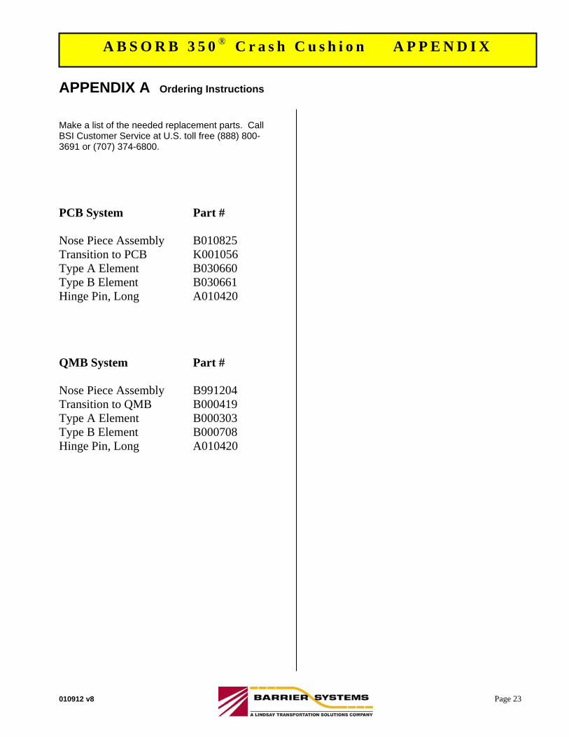
APPENDIX A Ordering Instructions
Make a list of the needed replacement parts. Call BSI Customer Service at U.S. toll free (888) 800-3691 or (707) 374-6800.
PCB System Part # Nose Piece Assembly B010825 Transition to PCB K001056 Type A Element B030660 Type B Element B030661 Hinge Pin, Long A010420 QMB System Part # Nose Piece Assembly B991204 Transition to QMB B000419 Type A Element B000303 Type B Element B000708 Hinge Pin, Long A010420
A B S O R B 3 5 0 ® C r a s h C u s h i o n A P P E N D I X
010912 v8 Page 24
A B S O R B 3 5 0 ® C r a s h C u s h i o n I N S T A L L A T I O N
APPENDIX B System Configurations
A B S O R B 3 5 0 ® C r a s h C u s h i o n A P P E N D I X
The ABSORB 350 Crash Cushion system has been fully designed and tested to comply with the evaluation requirements of the National Cooperative Highway Research Program Report 350 (NCHRP 350) for Test Levels 2 (70 km/h) and 3 (100 km/h). The Test Level 2 system contains five (5) Energy Absorbing Elements (EAB) and the Test Level 3 system contains nine (9) Energy Absorbing Elements. It is sometimes desirable to have a crash cushion that has an energy absorbing capacity that is less than Test Level 2, between test Level 2 and Test Level 3, or greater than Test Level 3. Therefore, the following table indicates the number of elements and the element placement configuration that would be required to absorb the kinetic energy of a 2000 kg (4400 lb.) vehicle impacting the front of the ABSORB 350 system, head-on and at the velocity indicated. Roadside safety features such as crash cushions must be installed in accordance with the AASHTO Roadside Design Guide, state and local standards and in conformance with the manufacturer’s instructions. Instructions from the manufacturer are available by contacting Barrier Systems, Inc., Customer Service Department at 1 888 800-3691 (Toll Free US) or 1 707 374-6800.
*Double hole elements must be cut on site, see page 14.
*
*

ADIEM 350 INSTALLATION & MAINTENANCE
An Economical Crash Cushion for Both Permanent And Temporary Installations
Trinity Highway Products
For Technical Assistance/Customer Service Call 1-800-772-7976
1
For Technical Assistance/Customer Service Call 1-800-772-7976
2
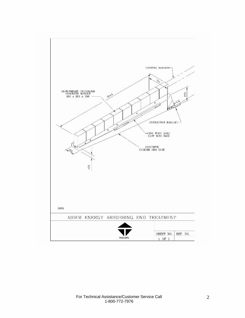
PRODUT OVERVIEW The ADIEM 350 (Advanced Dynamic Impact Extension Module) is a high performance, redirecting, energy-absorbing crash cushion and end treatment for portable and permanent protection of concrete barriers, bridge parapet rail, bridge piers and other hazards. The energy absorption elements of the ADIEM 350 are lightly reinforced, ultra low strength perlite concrete modules. The ADIEM dissipates the energy of an impact as the light-weight modules are crushed. All of the modules are identical with no specific order needed during installation.
CRASH PERFORMANCE The ADIEM 350 has successfully passed the testing requirements outlined in NCHRP Report 350, Test Level 3. A copy of this report can be obtained by contacting: Transportation Research Board National Research Council 2101 Constitution Avenue, N.W. Washington, D.C. 20418
RECOMMENDED TOOLS AND EQUIPMENT 1. Equipment to safely lift concrete base (30 feet in length and weighing 6 tons). 2. Equipment to off load module pallets without damaging crushable cartridges. 3. Air hammer/drill 35/50# along with appropriate power source. 4. Rock drill bit 1 3/8” x either 36", 42”, or 48” depending on installation surface. 5. Rock drill bit 1 1/4” x 12”. 6. Heavy sledge hammer. 7. Common motor oil or grease. 8. Socket and ratchet set 1 1/8” and 7/8”. 9. Wrenches 1 1/8” and 7/8”. 10. Standard caulking gun along with “liquid nails” adhesive cartridge. 11. Traffic control equipment. 12. Gloves and safety goggles. 13. Spray paint or chalk for marking anchor holes. 14. Safety gear for back protection when lifting. 15. Common mechanic’s “creeper” or other rolling device for moving modules. 16. Module installation strap (2” wide x 20’ long). 17. Large paint brush. 18. Bolt Cutters. 19. Heavy shop broom.
For Technical Assistance/Customer Service Call 1-800-772-7976
3
OFF LOADING ADIEM 350 Always use caution when working with construction equipment. Please wear safety goggles/glasses and gloves at all times while handling ADIEM 350 materials. Handling the ADIEM 350 Module Packages The ADIEM 350 modules are packaged ten (10) modules per pallet. The modules are covered with a durable cardboard and stacked back to back five (5) high. NOTE: The ADIEM module is designed to crush when impacted by a foreign body. Use caution when handling the modules! Use caution if using a box opener or other sharp edge to remove cardboard- if penetrated too deeply the module can be damaged! The recommended method for off loading the module packages is by forklift. Be careful not to damage modules with fork when establishing lift point! If using something other than a forklift (such as a crane sling) be certain the modules are secure and remain plumb during all times. Do not unpackage the modules until you have the ADIEM 350 base secure and are ready to start installing modules. Be aware of the environment around the modules, look for potential equipment (such as tractors, trucks, etc…) which might inadvertently damage the modules. Be sure to store the modules in a covered area away from heavy traffic that might allow the modules to be damaged. Handling the ADIEM 350 Precast Concrete Base The precast concrete base is 30 feet long and weights approximately 6 tons. There are lifting points strategically placed (see drawing SS 349) to allow the base to be balanced while lifting. The recommended method for off loading the base is by forklift (forks must be able to spread to minimal 5’ and handle minimal 24” wide base). This allows the installer to use one optimal piece of equipment to handle both the modules and the base. However, the base can be easily off loaded using any crane or piece of equipment capable of lifting such a load. If using something other than a forklift be certain to use a sling apparatus in the lifting points. Using a chain is not recommended because of chips and damages to the base. The ADIEM 350 base is made of durable concrete and can be stored in any safe location covered or uncovered. Handling the ADIEM 350 Hardware Crate Package The hardware typically will be packaged inside an open crate or strapped to a pallet. This package can be unloaded with the same equipment used to lift the base or module pallets.
For Technical Assistance/Customer Service Call 1-800-772-7976
4
Checking the Shipment Upon receipt of the shipment verify that all the parts listed on the bill of lading match what is on the truck. Using a pen physically check each part off the list, If any shortage or discrepancy exists clearly note it on the bill of lading. If you have a question about any part description call Trinity customer service.
INSTALLATION
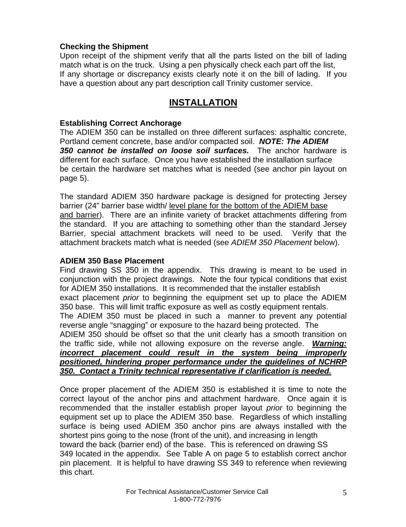
Establishing Correct Anchorage The ADIEM 350 can be installed on three different surfaces: asphaltic concrete, Portland cement concrete, base and/or compacted soil. NOTE: The ADIEM 350 cannot be installed on loose soil surfaces. The anchor hardware is different for each surface. Once you have established the installation surface be certain the hardware set matches what is needed (see anchor pin layout on page 5). The standard ADIEM 350 hardware package is designed for protecting Jersey barrier (24” barrier base width/ level plane for the bottom of the ADIEM base and barrier). There are an infinite variety of bracket attachments differing from the standard. If you are attaching to something other than the standard Jersey Barrier, special attachment brackets will need to be used. Verify that the attachment brackets match what is needed (see ADIEM 350 Placement below). ADIEM 350 Base Placement Find drawing SS 350 in the appendix. This drawing is meant to be used in conjunction with the project drawings. Note the four typical conditions that exist for ADIEM 350 installations. It is recommended that the installer establish exact placement prior to beginning the equipment set up to place the ADIEM 350 base. This will limit traffic exposure as well as costly equipment rentals. The ADIEM 350 must be placed in such a manner to prevent any potential reverse angle “snagging” or exposure to the hazard being protected. The ADIEM 350 should be offset so that the unit clearly has a smooth transition on the traffic side, while not allowing exposure on the reverse angle. Warning: incorrect placement could result in the system being improperly positioned, hindering proper performance under the guidelines of NCHRP 350. Contact a Trinity technical representative if clarification is needed. Once proper placement of the ADIEM 350 is established it is time to note the correct layout of the anchor pins and attachment hardware. Once again it is recommended that the installer establish proper layout prior to beginning the equipment set up to place the ADIEM 350 base. Regardless of which installing surface is being used ADIEM 350 anchor pins are always installed with the shortest pins going to the nose (front of the unit), and increasing in length toward the back (barrier end) of the base. This is referenced on drawing SS 349 located in the appendix. See Table A on page 5 to establish correct anchor pin placement. It is helpful to have drawing SS 349 to reference when reviewing this chart.
For Technical Assistance/Customer Service Call 1-800-772-7976
5
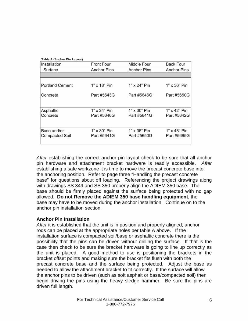
After establishing the correct anchor pin layout check to be sure that all anchor pin hardware and attachment bracket hardware is readily accessible. After establishing a safe workzone it is time to move the precast concrete base into the anchoring position. Refer to page three “Handling the precast concrete base” for questions about off loading. Referencing the project drawings along with drawings SS 349 and SS 350 properly align the ADIEM 350 base. The base should be firmly placed against the surface being protected with no gap allowed. Do not Remove the ADIEM 350 base handling equipment, the base may have to be moved during the anchor installation. Continue on to the anchor pin installation section. Anchor Pin Installation After it is established that the unit is in position and properly aligned, anchor rods can be placed at the appropriate holes per table A above. If the installation surface is compacted soil/base or asphaltic concrete there is the possibility that the pins can be driven without drilling the surface. If that is the case then check to be sure the bracket hardware is going to line up correctly as the unit is placed. A good method to use is positioning the brackets in the bracket offset points and making sure the bracket fits flush with both the precast concrete base and the surface being protected. Adjust the base as needed to allow the attachment bracket to fit correctly. If the surface will allow the anchor pins to be driven (such as soft asphalt or base/compacted soil) then begin driving the pins using the heavy sledge hammer. Be sure the pins are driven full length.
For Technical Assistance/Customer Service Call 1-800-772-7976
6
INSTALLATION If the installation surface is Portland cement concrete then mark (using spray paint or chalk) the pattern where the anchor holes are located. Remove the concrete base and using the 1 3/8” rock bit drill the anchor holes. Move the precast concrete base back into place, be sure the brackets are still correct, and then drive the anchor pins full length. Bracket Installation Be sure to read the mixing instructions provide with the epoxy chemical grout system and comply with the manufacturer’s warnings and recommendations. When attaching the ADIEM 350 bracket it is helpful to realize that the front half of the bracket (the part that will attach to the precast concrete base) will always be the same regardless of the site conditions. That portion of the bracket is constructed of 3” x 5” angle and is easily identified by the two 1 3/8” holes matching the precast base pattern (reference SS 349). Find the two brackets necessary to attach the base to the barrier (or whatever is being protected). Place the brackets on each side of the base and attach to the base using the two 1 1/8” x 25” Hex Bolts (part #5052G) an the 1 1/8” wrench and ratchet set. The part of the bracket that attaches to the barrier has four holes for anchoring, pick any three holes to be used. An extra anchor hole is available in case reinforcing steel is encountered while drilling. Using the 1 1/4” rock bit drill the three anchor holes, mix and inject the epoxy system, insert the 7/8” x 6” all thread rod (part #4616G), then allow appropriate time for the system to harden. Once the epoxy system has hardened use the 7/8” washer (part #3725G) and 7/8” hex nut (part #3735G) to secure the bracket to the barrier (or whatever is being protected). No special torque tooling is required, simply adjust to a “snug” fit using the 1 1/8” wrench and ratchet set. ADIEM 350 Module Placement Refer back to section one on page three “Handling the ADIEM 350 module packages.” Be sure there are no questions about this section. After the module pallet has been off loaded remove the protective cardboard covering, and any plastic wrapping. The modules are stacked with the “feet” (S3 x 5.7# beams) of the module facing out. The “feet” are cast in hard concrete and will remain rigid at all times in order to secure the module to the track in the precast base. When lifting ADIEM modules use back bracing and correct lifting techniques to prevent injury. The modules weigh approximately 175# each and should not be handled by one individual at a time. Using the motor oil or grease lubricant that track so that friction is at a minimum when sliding modules up the track. It might be necessary to lift up on the module to relieve any tackiness between modules.
For Technical Assistance/Customer Service Call 1-800-772-7976
7
Do this by taking the palm of the hand and grasping each module “foot” and lifting the module. Most installers prefer to manually lift the modules; however, if that is not feasible a strap, or hoist can be used to lift the module by the “feet” only. The module should be lifted using two men positioned on each side of the module. Lift the module and gently place it (feet down- just like it will be installed on the track) on the mechanic’s “creeper” or other rolling device. Both men should stay on each side of the module for balance- the module will be top heavy so it must be held tightly. Discard the thin foam sheet that separates each module. Roll the module to the front of the precast concrete base. Another option is to disregard the rolling concept and just carry the module to the base (using sage lifting technique). Note how the l-beam “feet” will fit inside the rollformed track of the base. Lift the module and slide the module up the track until both feet are in the track. All the modules are identical with no front or back, so no particular sequence is necessary. The same two men should position themselves on each side of the base. Take the 2” module strap and position it toward the bottom two inches of the module, running the ends out toward the two previously positioned men. Note that the bottom 2-3” portion of the module is made of hard concrete- any pressure should be directed at that layer. Pull the module up the track until it becomes awkward, then push up the track applying pressure only to the bottom 2-3” portion of the module. The module should fit flush at the back of the base. Another option is to disregard the strap and push (bottom 2” layer only) the module up the track from the beginning (using safe technique). Repeat this process with all ten modules. Be sure that the modules fit tight against each other. After the modules are all installed use the brush and the ADIEM coat to completely recoat all modules. The coat should be brushed or applied heavily to any areas where the coating was “bruised” or damaged during the installation process. Any spot where it appears the coating might be penetrated should be heavily coated. Delineation Reference drawings 5904B and 5914B in the appendix. Note that drawing 5904B is for roadside left and right delineation needs (with two required), while drawing 5914B is for a “gore” application with both left and right delineation. Using the caulking gun apply “liquid nails” adhesive, and install the delineator per the instructions on the appropriate drawing. The ADIEM 350 is ready for operation. As with all safety products proper maintenance is critical to future success. Please read through the maintenance section and distribute to the appropriate maintaining agency.
For Technical Assistance/Customer Service Call 1-800-772-7976
8
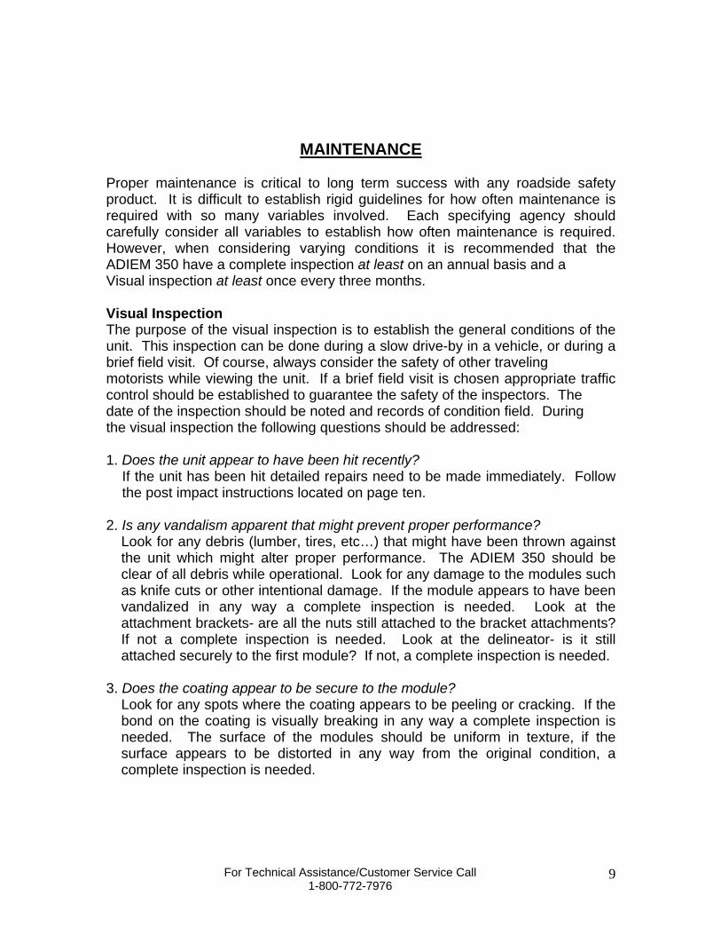
MAINTENANCE Proper maintenance is critical to long term success with any roadside safety product. It is difficult to establish rigid guidelines for how often maintenance is required with so many variables involved. Each specifying agency should carefully consider all variables to establish how often maintenance is required. However, when considering varying conditions it is recommended that the ADIEM 350 have a complete inspection at least on an annual basis and a Visual inspection at least once every three months. Visual Inspection The purpose of the visual inspection is to establish the general conditions of the unit. This inspection can be done during a slow drive-by in a vehicle, or during a brief field visit. Of course, always consider the safety of other traveling motorists while viewing the unit. If a brief field visit is chosen appropriate traffic control should be established to guarantee the safety of the inspectors. The date of the inspection should be noted and records of condition field. During the visual inspection the following questions should be addressed: 1. Does the unit appear to have been hit recently?
If the unit has been hit detailed repairs need to be made immediately. Follow the post impact instructions located on page ten.
2. Is any vandalism apparent that might prevent proper performance?
Look for any debris (lumber, tires, etc…) that might have been thrown against the unit which might alter proper performance. The ADIEM 350 should be clear of all debris while operational. Look for any damage to the modules such as knife cuts or other intentional damage. If the module appears to have been vandalized in any way a complete inspection is needed. Look at the attachment brackets- are all the nuts still attached to the bracket attachments? If not a complete inspection is needed. Look at the delineator- is it still attached securely to the first module? If not, a complete inspection is needed.
3. Does the coating appear to be secure to the module?
Look for any spots where the coating appears to be peeling or cracking. If the bond on the coating is visually breaking in any way a complete inspection is needed. The surface of the modules should be uniform in texture, if the surface appears to be distorted in any way from the original condition, a complete inspection is needed.
For Technical Assistance/Customer Service Call 1-800-772-7976
9
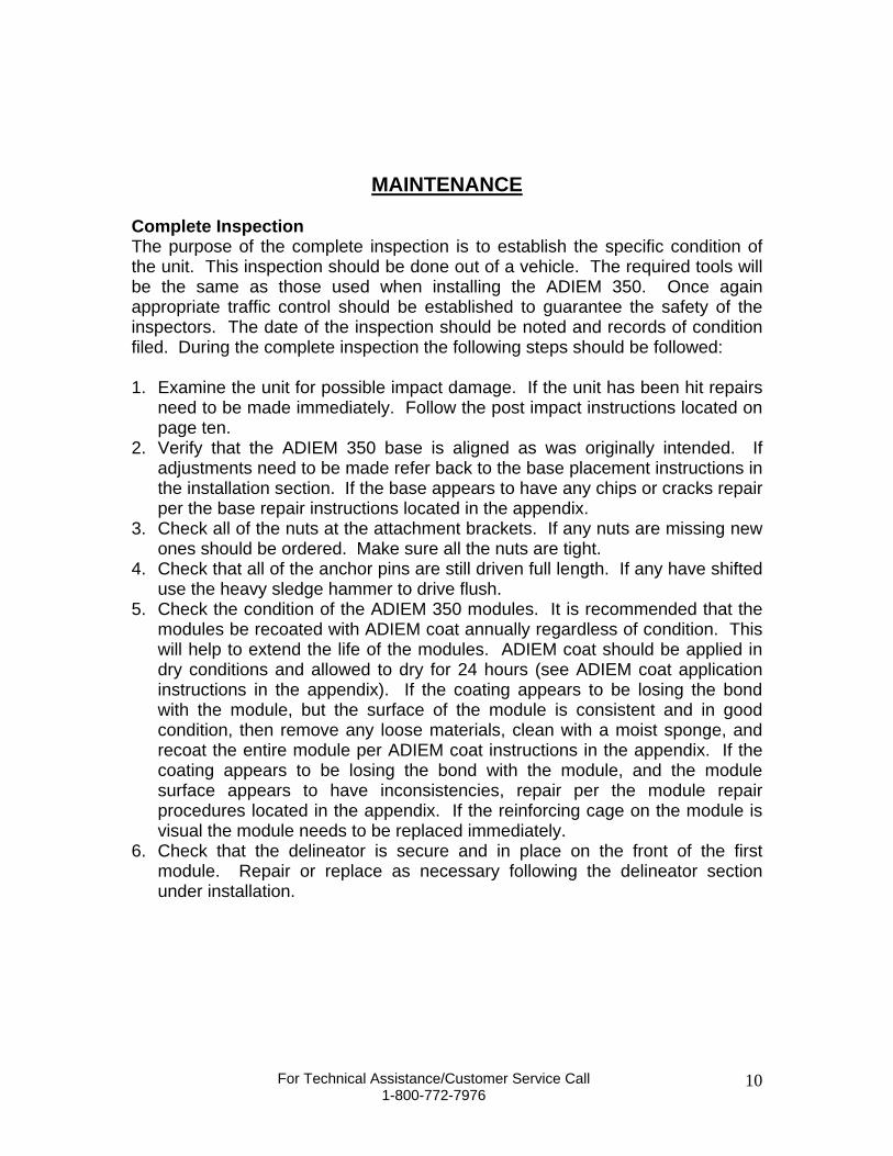
MAINTENANCE Complete Inspection The purpose of the complete inspection is to establish the specific condition of the unit. This inspection should be done out of a vehicle. The required tools will be the same as those used when installing the ADIEM 350. Once again appropriate traffic control should be established to guarantee the safety of the inspectors. The date of the inspection should be noted and records of condition filed. During the complete inspection the following steps should be followed: 1. Examine the unit for possible impact damage. If the unit has been hit repairs
need to be made immediately. Follow the post impact instructions located on page ten.
2. Verify that the ADIEM 350 base is aligned as was originally intended. If adjustments need to be made refer back to the base placement instructions in the installation section. If the base appears to have any chips or cracks repair per the base repair instructions located in the appendix.
3. Check all of the nuts at the attachment brackets. If any nuts are missing new ones should be ordered. Make sure all the nuts are tight.
4. Check that all of the anchor pins are still driven full length. If any have shifted use the heavy sledge hammer to drive flush.
5. Check the condition of the ADIEM 350 modules. It is recommended that the modules be recoated with ADIEM coat annually regardless of condition. This will help to extend the life of the modules. ADIEM coat should be applied in dry conditions and allowed to dry for 24 hours (see ADIEM coat application instructions in the appendix). If the coating appears to be losing the bond with the module, but the surface of the module is consistent and in good condition, then remove any loose materials, clean with a moist sponge, and recoat the entire module per ADIEM coat instructions in the appendix. If the coating appears to be losing the bond with the module, and the module surface appears to have inconsistencies, repair per the module repair procedures located in the appendix. If the reinforcing cage on the module is visual the module needs to be replaced immediately.
6. Check that the delineator is secure and in place on the front of the first module. Repair or replace as necessary following the delineator section under installation.
For Technical Assistance/Customer Service Call 1-800-772-7976
10
CO
NT
EN
TS
DE
SC
RIP
TIO
NN
OT
ES
FO
R Q
UA
DG
UA
RD
CZ
SY
ST
EM
ON
A P
LA
TE
QU
AD
GU
AR
D C
Z S
YS
TE
M O
N A
PL
AT
E
DR
AW
ING
NU
MB
ER
/SH
EE
T N
UM
BE
R
60-24-93 /
1 o
f 4
QU
AD
GU
AR
D C
Z S
YS
TE
M O
N A
PL
AT
E
60-24-93 /
2 o
f 4
60-24-93 /
3 o
f 4
60
-2
4-9
3 /
4 o
f 4
35
-4
0-0
7 /
1 o
f 1
35-40-05 /
1 o
f 1
35-40-04 /
1 o
f 1
35-40-28 /
1 o
f 2
35
-4
0-2
8 /
2 o
f 2
35-40-23 /
1 o
f 1
FD
OT
AP
PR
OV
ED
DR
AW
ING
Sh
eet N
o.
1 o
f 13
QP
L N
o. S
544-0031
1.
Th
e e
nerg
y a
bso
rb
ing
sy
ste
m r
ep
resen
ted
on
th
is Q
uali
fie
d P
ro
du
cts
Lis
t (Q
PL
) d
raw
ing
is a
pro
prie
tary
desig
n b
y
E
nerg
y A
bso
rp
tio
n S
yste
ms,
In
c.
an
d m
ark
ete
d u
nd
er t
he n
am
e Q
uad
gu
ard
CZ
Sy
ste
m O
n A
Pla
te.
An
y i
nfrin
gem
en
t
on t
he r
ights
of t
he d
esig
ner s
hall
be t
he s
ole
responsib
ilit
y o
f t
he u
ser.
2.
Th
e Q
uad
gu
ard
CZ
Sy
ste
m O
n A
Pla
te i
s f
or t
em
po
rary
use a
nd
is l
imit
ed
to
co
nstr
ucti
on
zo
nes.
T
he s
yste
m m
ay
be u
sed
at
an
y l
ocati
on
wh
ere a
tem
po
rary
red
irecti
ve c
rash
cu
sh
ion
is c
all
ed
fo
r i
n t
he p
lan
s.
3. T
he Q
uadguard C
Z S
yste
m O
n A
Pla
te i
s a
redir
ecti
ve, non-gati
ng c
rash c
ushio
n.
4. T
he Q
uadguard C
Z S
yste
m O
n A
Pla
te m
ay b
e c
onfig
ured f
or d
esig
n s
peeds u
p t
o 7
0 m
ph.
5. T
he Q
uadguard C
Z S
yste
m O
n A
Pla
te s
hall
be i
nsta
lled i
n a
ccordance w
ith t
he m
anufactu
rer’s d
eta
ils, draw
ings,
p
ro
ced
ures a
nd
sp
ecif
icati
on
s a
s r
eferen
ced
in
th
ese d
raw
ing
s.
Th
e C
on
tracto
r s
hall
certi
fy
th
at
all
mate
ria
ls
fu
rn
ish
ed
meet
the s
pecif
ied
req
uir
em
en
ts.
T
em
po
rary
Co
ncrete
barrie
r w
all
s a
bu
ttin
g t
he Q
uad
gu
ard
CZ
Sy
ste
m O
n A
Pla
te m
ust
be a
deq
uate
ly a
nch
ored
for p
roper i
mpact
perform
ance i
n a
ccordance w
ith I
ndex N
o. 415.
6.
Len
gth
of n
eed
an
d t
ran
sit
ion
s s
hall
be i
n a
cco
rd
an
ce w
ith
th
e r
esp
ecti
ve Q
uad
gu
ard
draw
ing
s i
n t
he D
esig
n
S
tandards o
r p
oste
d o
n t
he Q
PL
.
7.
Th
e n
um
ber o
f b
ay
s t
o b
e u
sed
in
a s
pecif
ic u
nit
wil
l b
e d
ete
rm
ined
by
th
e d
esig
n s
peed
, ex
cep
t w
here t
he
E
ngin
eer d
ete
rm
ines a
noth
er s
peed i
s m
ore a
ppli
cable
.
8.
A y
ell
ow
Ty
pe ~
o
bje
ct
mark
er s
hall
be c
en
tered
3’ i
n f
ro
nt
of t
he n
ose o
f t
he Q
uad
gu
ard
CZ
Sy
ste
m O
n A
Pla
te.
M
ou
nti
ng
hard
ware s
hall
be i
n c
on
fo
rm
an
ce w
ith
In
dex
No
s.
11
86
0 a
nd
11
86
5.
Th
e c
ost
of t
he o
bje
ct
mark
er
shall
be i
nclu
ded i
n t
he c
ost
of t
he Q
uadguard C
Z S
yste
m O
n A
Pla
te.
9.
Th
e d
riv
ab
le p
ile a
nch
or s
yste
m m
ay
be u
sed
as a
n a
ltern
ati
ve t
o t
he o
ther f
ou
nd
ati
on
op
tio
ns s
ho
wn
. T
he c
ost
o
f t
he d
riv
ab
le p
ile a
nch
or s
yste
m s
hall
be i
nclu
ded
in
th
e c
ost
of t
he Q
uad
gu
ard
CZ
Sy
ste
m O
n A
Pla
te.
10. T
em
porary Q
uadguard C
Z S
yste
m O
n A
Pla
te u
nit
s w
ill
be p
aid
for u
nder t
he c
ontr
act
unit
pric
e f
or I
mpact
A
ttenuato
r-C
rash C
ushio
n (
Tem
porary) (
Redir
ecti
ve O
pti
on), L
O.
QU
AD
GU
AR
D S
YS
TE
M C
Z O
N A
PL
AT
E F
OR
CO
NS
TR
UC
TIO
N Z
ON
ES
W/D
RIV
AB
LE
PIL
E
AN
CH
OR
AG
E
QP
CZ
DP
A-U
/1 o
f 1
35
-4
0-7
0/1
of 1
QU
AD
GU
AR
D S
YS
TE
M C
Z O
N A
PL
AT
E
DR
IVA
BL
E P
ILE
AN
CH
OR
(D
PA
)
AS
SE
MB
LY
Th
e c
on
tracto
r h
as t
he o
ptio
n t
o i
nstall r
eflectiv
e s
heetin
g o
n t
he n
ose o
f t
he c
rash
cu
sh
io
n i
n l
ieu
of p
lacin
g t
he y
ello
w T
yp
e I
Ob
ject M
ark
er 3
feet i
n f
ro
nt o
f t
he n
ose
of t
he c
rash
cu
sh
io
n.
Th
e s
heetin
g t
o b
e u
sed
mu
st b
e s
olid
yello
w,
Ty
pe I
II o
r b
etter,
an
d m
ust
be a
pro
du
ct
liste
d o
n t
he D
ep
artm
en
t’s Q
uali
fie
d P
ro
du
cts
Lis
t (Q
PL
).
Th
e
sheeting t
o b
e a
pplied t
o t
he n
ose o
f t
he c
rash c
ushion s
hall b
e a
minim
um
of 3
60
square i
nches w
ith a
min
imum
heig
ht
of 1
5 i
nches.
A
pril 30, 2009
CZ
ON
A P
LA
TE
, M
P-3
AN
CH
OR
KIT
,
QG
, 3
BA
Y B
/U,
3 B
AY
AD
AP
TO
R P
LA
TE
S
CZ
ON
A P
LA
TE
, M
P-3
AN
CH
OR
KIT
,
QG
, 3
BA
Y B
/U,
3 B
AY
AD
AP
TO
R P
LA
TE
S
24" &
30" S
YS
TE
MS
CZ
ON
A P
LA
TE
, M
P-3
AN
CH
OR
KIT
,
QG
, 3
BA
Y B
/U,
3 B
AY
AD
AP
TO
R P
LA
TE
S
36" S
YS
TE
M
QU
AD
GU
AR
D S
YS
TE
M
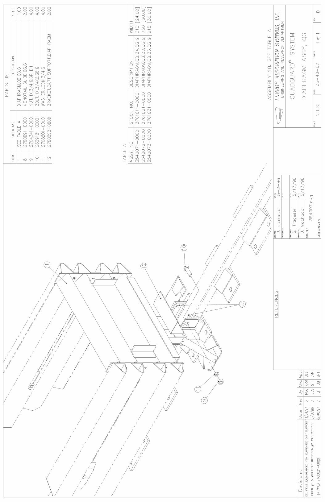
DIA
PH
RA
GM
AS
SY
., Q
G
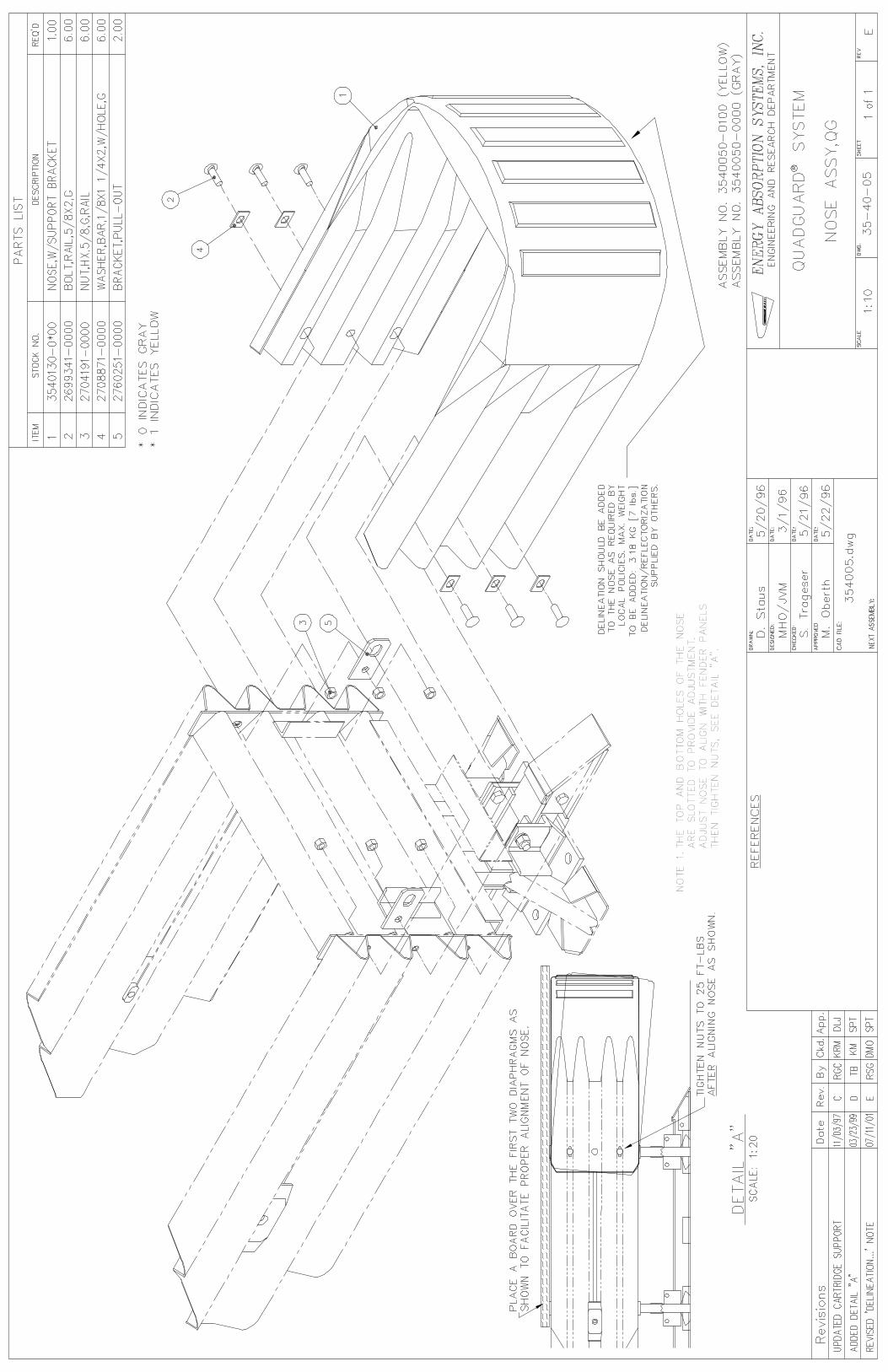
QU
AD
GU
AR
D S
YS
TE
M
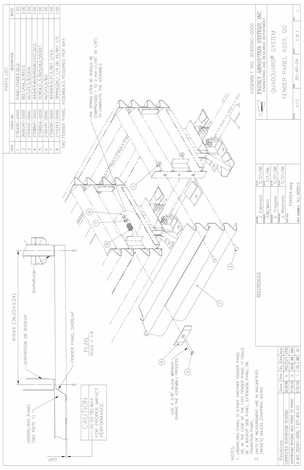
FE
ND
ER
PA
NE
L A
SS
Y.,
QG
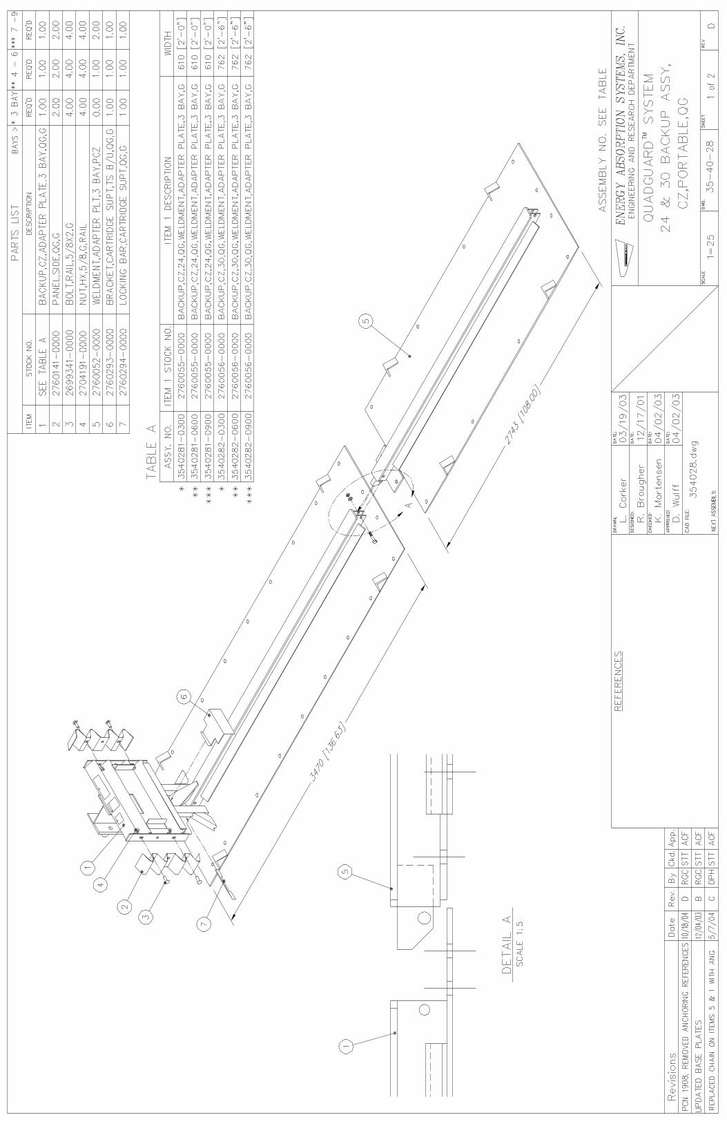
QU
AD
GU
AR
D S
YS
TE
M
24 &
30 B
AC
KU
P A
SS
Y.,
CZ
, P
OR
TA
BL
E,
QG
QU
AD
GU
AR
D S
YS
TE
M
36
BA
CK
UP
AS
SY
.,
CZ
, P
OR
TA
BL
E,
QG
QU
AD
GU
AR
D S
YS
TE
M
CZ
ON
A P
LA
TE
, Q
G,
LIF
TIN
G K
IT &
IN
ST
RU
CT
ION
S
QU
AD
GU
AR
D S
YS
TE
M
NO
SE
AS
SY
., Q
G
NO
TE
8 A
LT
ER
NA
TIV
E: