Embed Size (px)
Citation preview
MATERIALS, MANUFACTURING AND TEST DEVELOPMENT OF A COMPOSITE FAN BLADE LEADING EDGE SUBCOMPONENT FOR
IMPROVED IMPACT RESISTANCE
Katherine M. Handschuh2, Sandi G. Miller1, Matthew J. Sinnott2, Lee W. Kohlman1, Gary D. Roberts1, J. Michael Pereira1, and Charles R. Ruggeri1 1NASA Glenn Research Center, Cleveland, OH 44135
2NASA LERCIP Intern, NASA Glenn Research Center, Cleveland, OH 44135
ABSTRACT Application of polymer matrix composite materials for jet engine fan blades is becoming attractive as an alternative to metallic blades; particularly for large engines where significant weight savings are recognized on moving to a composite structure. However, the weight benefit of the composite of is offset by a reduction of aerodynamic efficiency resulting from a necessary increase in blade thickness; relative to the titanium blades. Blade dimensions are largely driven by resistance to damage on bird strike. Further development of the composite material is necessary to allow composite blade designs to approximate the dimensions of a metallic fan blade. The reduction in thickness over the state of the art composite blades is expected to translate into structural weight reduction, improved aerodynamic efficiency, and therefore reduced fuel consumption. This paper presents test article design, subcomponent blade leading edge fabrication, test method development, and initial results from ballistic impact of a gelatin projectile on the leading edge of composite fan blades. The simplified test article geometry was developed to realistically simulate a blade leading edge while decreasing fabrication complexity. Impact data is presented on baseline composite blades and toughened blades; where a considerable improvement to impact resistance was recorded.
1. INTRODUCTION
The purpose of the fan blades on high bypass turbofan jet engines is to accelerate air for propulsion, while a smaller fraction is passed into the compressor section of the engine. At take-off and landing, these fan blades are susceptible to potentially damaging bird strike events that could lead to engine shutdown. As a result, blade impact strength specifications are outlined by the Federal Aviation Administration (FAA) and are prerequisite to blade implementation into commercial aircraft.[1] Meeting the standards set forth by the FAA requires a necessary, but costly, full scale engine test where the pass/fail criteria are dependent on engine size. FAA regulations outline three categories of bird strike: large single bird, small or medium flocking bird, and large flocking bird. For a large single bird, the ingestion speed of the FAA test of turbofan engines currently in service is 200 knots (337.5 ft/s). It is understood that the engine will shut down with the ingestion of a large single bird. Following ingestion of small and medium flocking bird(s) the engine must generate 75% of take-off power or thrust and with only a momentary drop of less than three seconds. For large flocking birds, the engine needs to operate for a twenty minute ‘run-on’. The test to meet these criteria includes evaluation of
https://ntrs.nasa.gov/search.jsp?R=20150000887 2020-05-02T12:44:03+00:00Z
engine performance at different power ratings until shutdown. These standards affect the design parameters of fan blades.
The primary drivers for technology development within the commercial aircraft community include cost savings and efficiency gains. Common methods to meet these challenges include weight reduction and increased aerodynamic efficiency of aircraft components. The large fan blades are an attractive technology for development as both weight reduction and enhanced efficiency are feasible. The successful application of carbon fiber reinforced polymer matrix composite (PMC) fan blades by GE [2] has significantly reduced engine weight; relative to a structure using titanium blades. The weight reduction is recognized not only in the blades themselves, but also in secondary engine components such as bearings, mounts, and fan containment structures. The limitation of the composite blades however, is that the PMC turbofan blades must be thicker than conventional titanium blades to meet the strength requirements for bird strikes set forth by the FAA. Thus, the aerodynamic efficiency of the PMC blades is reduced when compared to titanium blades. This paper addresses two parallel approaches to improving the aerodynamic efficiency of PMC blades, including (1) decreased fan blade thickness through improved damage tolerance of the composite, and (2) material studies that would enable camber change of the blade between cruise and take-off. The method considered to improve damage tolerance includes incorporation of a thermoplastic interlayer to enhance interlaminar strain capability, and reduce delamination on impact. The second path to increased aerodynamic efficiency of fan blades includes embedding shape memory alloy (SMA) ribbons into composite blades. Embedding such materials holds the possibility for variable camber fan blades; where shape change occurs between take-off and cruise speeds for increased fan efficiency. Currently, fan blades are typically designed for cruise and operate at reduced efficiency during take-off. SMAs are metallic materials that undergo thermally and/or mechanically induced phase transitions (martensitic/austenitic) resulting in high reversible strain capability. These phase transitions, when thermally induced, can be used to generate stress and/or strain for actuation.
The specific goals of this study were to (1) provide an impact test method for a blade leading edge subcomponent structure, design a realistic laminate lay-up for the leading edge subcomponent test articles, and (2) identify material solutions to improve composite impact performance and allow for thinner fan blade structures. The test article design and test methodology were developed based on published experimental work of simplified simulation of bird strikes.
2. EXPERIMENTAL
2.1 Materials
IM7/8551-7 uni-directional prepreg was used for leading edge fabrication. Due to shipping error, the prepreg was exposed to ambient conditions during shipping and possibly partially cured. It was possible to fabricate composite panels and blade test articles with no apparent defects after cure using this material, although it is possible that material properties could have been reduced by the prior ambient exposure. Since the purpose of this work was to evaluate relative performance of a baseline composite to composites with embedded material, it was decided that this material would be suitable for this work.
A thermoplastic polyurethane veil was incorporated into the leading edge structure to evaluate its influence on the composite damage tolerance. The average areal weight of the TPU veil was 15 gsm and the average fiber diameter was on the nanometer scale. Interlayer veils used for toughening have been shown to improve composite fracture toughness. [3] Due to the shipping error, IM7/8552 was used for Panel evaluation.
2.2 Test Article Geometry
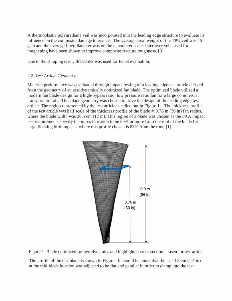
Material performance was evaluated through impact testing of a leading edge test article derived from the geometry of an aerodynamically optimized fan blade. The optimized blade utilized a modern fan blade design for a high-bypass ratio, low pressure ratio fan for a large commercial transport aircraft. This blade geometry was chosen to drive the design of the leading edge test article. The region represented by the test article is called out in Figure 1. The thickness profile of the test article was half scale of the thickness profile of the blade at 0.76 m (30 in) fan radius, where the blade width was 30.5 cm (12 in). This region of a blade was chosen as the FAA impact test requirements specify the impact location to be 50% or more from the root of the blade for large flocking bird impacts, where this profile chosen is 83% from the root. [1]
Figure 1. Blade optimized for aerodynamics and highlighted cross section chosen for test article
The profile of the test blade is shown in Figure . It should be noted that the last 3.8 cm (1.5 in) at the mid-blade location was adjusted to be flat and parallel in order to clamp into the test
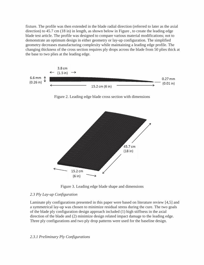
fixture. The profile was then extended in the blade radial direction (referred to later as the axial direction) to 45.7 cm (18 in) in length, as shown below in Figure , to create the leading edge blade test article. The profile was designed to compare various material modifications; not to demonstrate an optimum design in either geometry or lay-up configuration. The simplified geometry decreases manufacturing complexity while maintaining a leading edge profile. The changing thickness of the cross section requires ply drops across the blade from 50 plies thick at the base to two plies at the leading edge.
Figure 2. Leading edge blade cross section with dimensions
Figure 3. Leading edge blade shape and dimensions
2.3 Ply Lay-up Configuration
Laminate ply configurations presented in this paper were based on literature review [4,5] and a symmetrical lay-up was chosen to minimize residual stress during the cure. The two goals of the blade ply configuration design approach included (1) high stiffness in the axial direction of the blade and (2) minimize design related impact damage to the leading edge. Three ply configurations and two ply drop patterns were used for the baseline design.
2.3.1 Preliminary Ply Configurations
Two separate lay-up designs were initially considered based on literature review [4]. These designs were labeled A1 and A2; as outlined in Table 1.
Table 1. Initial Ply Designs
Ply Drop Type Ply Lay-up Version Configuration Test Articles
A 1 [90/(-45/0/+45/0)3/012]s C001-C002
A 2 [90/(-45/0/+45/0)3/03/(90/0)3/03]s C003
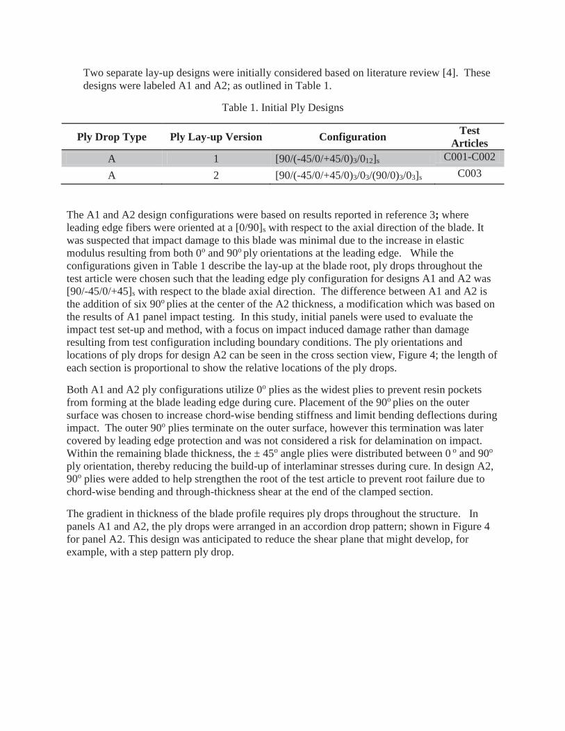
The A1 and A2 design configurations were based on results reported in reference 3; where leading edge fibers were oriented at a [0/90]s with respect to the axial direction of the blade. It was suspected that impact damage to this blade was minimal due to the increase in elastic modulus resulting from both 0o and 90o ply orientations at the leading edge. While the configurations given in Table 1 describe the lay-up at the blade root, ply drops throughout the test article were chosen such that the leading edge ply configuration for designs A1 and A2 was [90/-45/0/+45]s with respect to the blade axial direction. The difference between A1 and A2 is the addition of six 90o plies at the center of the A2 thickness, a modification which was based on the results of A1 panel impact testing. In this study, initial panels were used to evaluate the impact test set-up and method, with a focus on impact induced damage rather than damage resulting from test configuration including boundary conditions. The ply orientations and locations of ply drops for design A2 can be seen in the cross section view, Figure 4; the length of each section is proportional to show the relative locations of the ply drops.
Both A1 and A2 ply configurations utilize 0o plies as the widest plies to prevent resin pockets from forming at the blade leading edge during cure. Placement of the 90o plies on the outer surface was chosen to increase chord-wise bending stiffness and limit bending deflections during impact. The outer 90o plies terminate on the outer surface, however this termination was later covered by leading edge protection and was not considered a risk for delamination on impact. Within the remaining blade thickness, the ± 45o angle plies were distributed between 0 o and 90o ply orientation, thereby reducing the build-up of interlaminar stresses during cure. In design A2, 90o plies were added to help strengthen the root of the test article to prevent root failure due to chord-wise bending and through-thickness shear at the end of the clamped section.
The gradient in thickness of the blade profile requires ply drops throughout the structure. In panels A1 and A2, the ply drops were arranged in an accordion drop pattern; shown in Figure 4 for panel A2. This design was anticipated to reduce the shear plane that might develop, for example, with a step pattern ply drop.
Figure 4. A2 ply lay-up, through thickness view
2.2.2 Secondary Ply Configurations Modifications to the initial blade ply configuration were made following impact test of the preliminary design. The lay-up configurations of A3 and B1 are provided in Table 2 with the difference being ply drop pattern and location of ply terminations. The accordion ply drop pattern was retained in panel A3, whereas B1 was fabricated with a defined ply drop pattern. The B1 design was established to provide a systematic approach to the ply termination points, allowing better balance between +45 o and -45 o terminations across the ply drops. The only difference between designs A3 and B1 is that ‘A’ has ‘accordion pattern’ or random ply drops while ‘B’ is a systematic ply drop pattern. The ply drop location and the lay-up configuration of the B1 type is in Figure
Table 2. Secondary Ply Designs
Ply Drop Type Ply Lay-up Version Configuration Test Articles
A 3 [90/(-45/0/+45/0)6/0]s C005 B 1 [90/(-45/0/+45/0)6/0]s C006-C008
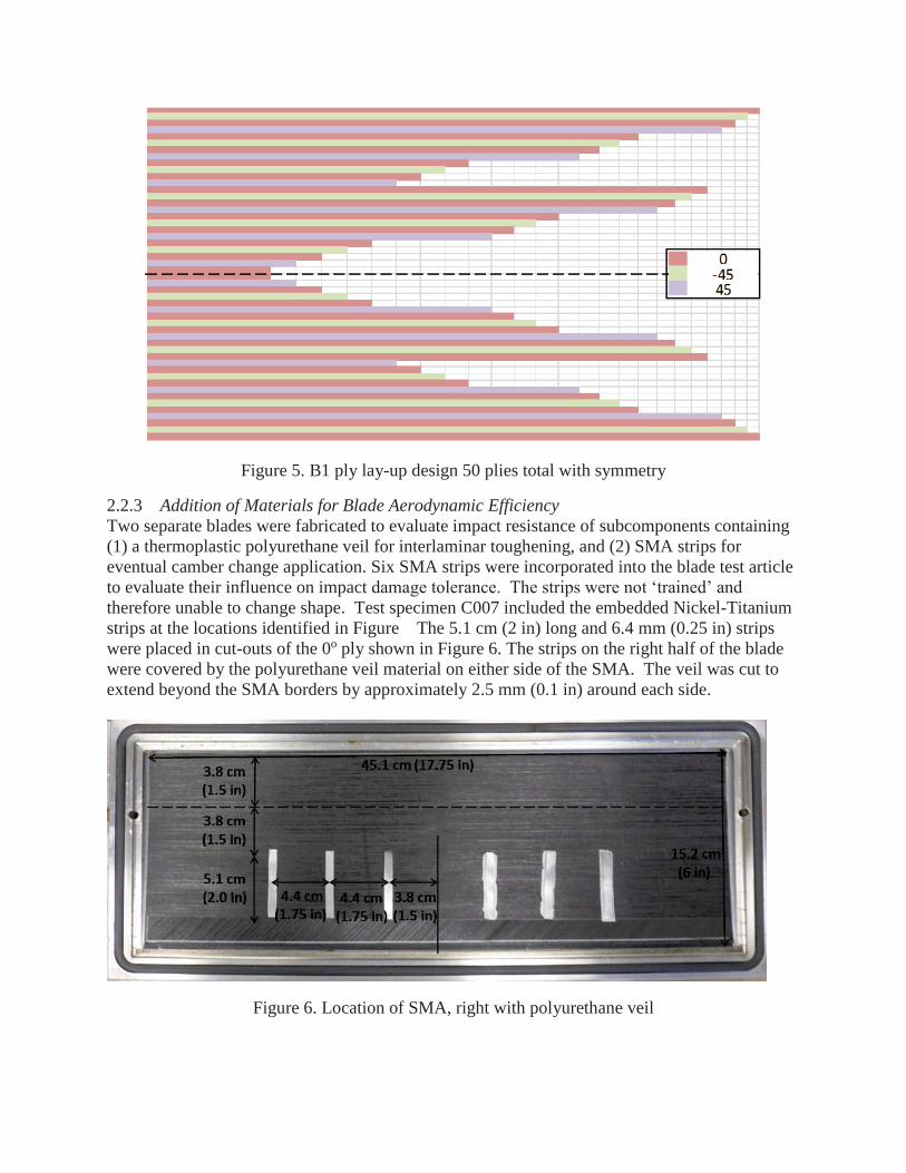
Figure 5. B1 ply lay-up design 50 plies total with symmetry
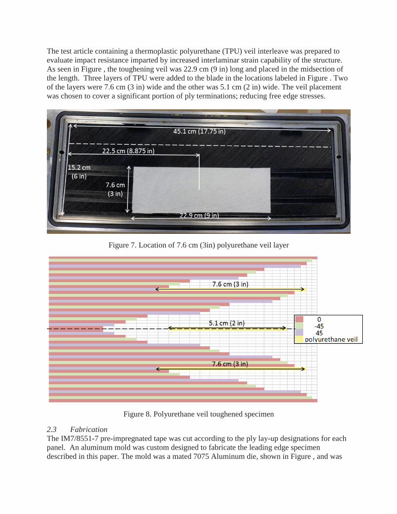
2.2.3 Addition of Materials for Blade Aerodynamic Efficiency Two separate blades were fabricated to evaluate impact resistance of subcomponents containing (1) a thermoplastic polyurethane veil for interlaminar toughening, and (2) SMA strips for eventual camber change application. Six SMA strips were incorporated into the blade test article to evaluate their influence on impact damage tolerance. The strips were not ‘trained’ and therefore unable to change shape. Test specimen C007 included the embedded Nickel-Titanium strips at the locations identified in Figure The 5.1 cm (2 in) long and 6.4 mm (0.25 in) strips were placed in cut-outs of the 0o ply shown in Figure 6. The strips on the right half of the blade were covered by the polyurethane veil material on either side of the SMA. The veil was cut to extend beyond the SMA borders by approximately 2.5 mm (0.1 in) around each side.
Figure 6. Location of SMA, right with polyurethane veil
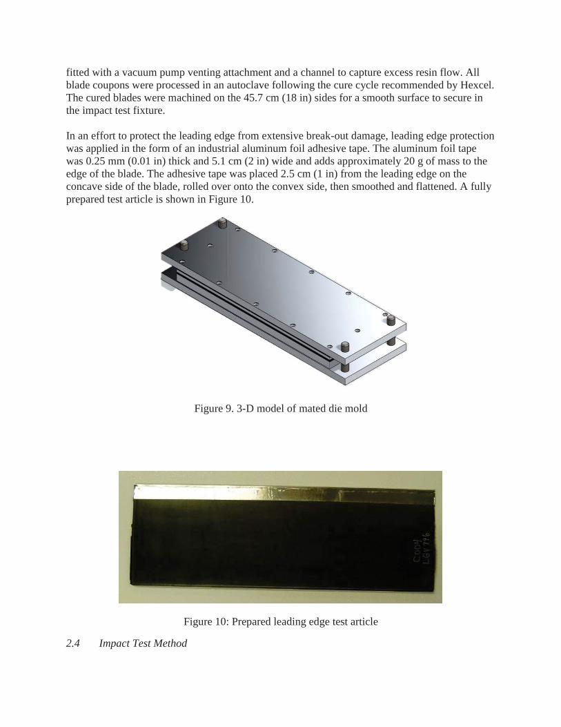
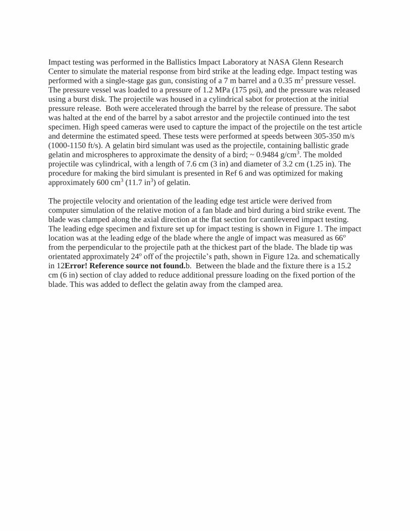
The test article containing a thermoplastic polyurethane (TPU) veil interleave was prepared to evaluate impact resistance imparted by increased interlaminar strain capability of the structure. As seen in Figure , the toughening veil was 22.9 cm (9 in) long and placed in the midsection of the length. Three layers of TPU were added to the blade in the locations labeled in Figure . Two of the layers were 7.6 cm (3 in) wide and the other was 5.1 cm (2 in) wide. The veil placement was chosen to cover a significant portion of ply terminations; reducing free edge stresses.
Figure 7. Location of 7.6 cm (3in) polyurethane veil layer
Figure 8. Polyurethane veil toughened specimen
2.3 Fabrication The IM7/8551-7 pre-impregnated tape was cut according to the ply lay-up designations for each panel. An aluminum mold was custom designed to fabricate the leading edge specimen described in this paper. The mold was a mated 7075 Aluminum die, shown in Figure , and was
fitted with a vacuum pump venting attachment and a channel to capture excess resin flow. All blade coupons were processed in an autoclave following the cure cycle recommended by Hexcel. The cured blades were machined on the 45.7 cm (18 in) sides for a smooth surface to secure in the impact test fixture. In an effort to protect the leading edge from extensive break-out damage, leading edge protection was applied in the form of an industrial aluminum foil adhesive tape. The aluminum foil tape was 0.25 mm (0.01 in) thick and 5.1 cm (2 in) wide and adds approximately 20 g of mass to the edge of the blade. The adhesive tape was placed 2.5 cm (1 in) from the leading edge on the concave side of the blade, rolled over onto the convex side, then smoothed and flattened. A fully prepared test article is shown in Figure 10.
Figure 9. 3-D model of mated die mold
Figure 10: Prepared leading edge test article
2.4 Impact Test Method
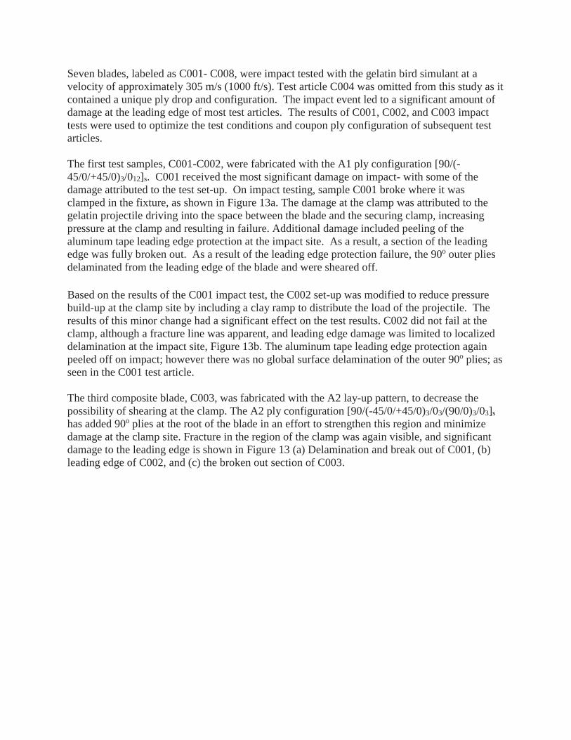
Impact testing was performed in the Ballistics Impact Laboratory at NASA Glenn Research Center to simulate the material response from bird strike at the leading edge. Impact testing was performed with a single-stage gas gun, consisting of a 7 m barrel and a 0.35 m2 pressure vessel. The pressure vessel was loaded to a pressure of 1.2 MPa (175 psi), and the pressure was released using a burst disk. The projectile was housed in a cylindrical sabot for protection at the initial pressure release. Both were accelerated through the barrel by the release of pressure. The sabot was halted at the end of the barrel by a sabot arrestor and the projectile continued into the test specimen. High speed cameras were used to capture the impact of the projectile on the test article and determine the estimated speed. These tests were performed at speeds between 305-350 m/s (1000-1150 ft/s). A gelatin bird simulant was used as the projectile, containing ballistic grade gelatin and microspheres to approximate the density of a bird; ~ 0.9484 g/cm3. The molded projectile was cylindrical, with a length of 7.6 cm (3 in) and diameter of 3.2 cm (1.25 in). The procedure for making the bird simulant is presented in Ref 6 and was optimized for making approximately 600 cm3 (11.7 in3) of gelatin. The projectile velocity and orientation of the leading edge test article were derived from computer simulation of the relative motion of a fan blade and bird during a bird strike event. The blade was clamped along the axial direction at the flat section for cantilevered impact testing. The leading edge specimen and fixture set up for impact testing is shown in Figure 1. The impact location was at the leading edge of the blade where the angle of impact was measured as 66o from the perpendicular to the projectile path at the thickest part of the blade. The blade tip was orientated approximately 24o off of the projectile’s path, shown in Figure 12a. and schematically in 12Error! Reference source not found.b. Between the blade and the fixture there is a 15.2 cm (6 in) section of clay added to reduce additional pressure loading on the fixed portion of the blade. This was added to deflect the gelatin away from the clamped area.
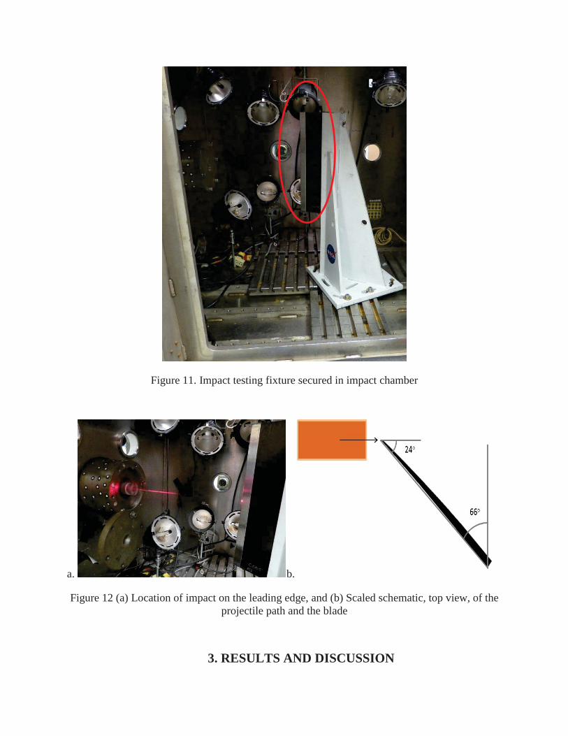
Figure 11. Impact testing fixture secured in impact chamber
a. b.
Figure 12 (a) Location of impact on the leading edge, and (b) Scaled schematic, top view, of the projectile path and the blade
3. RESULTS AND DISCUSSION
Seven blades, labeled as C001- C008, were impact tested with the gelatin bird simulant at a velocity of approximately 305 m/s (1000 ft/s). Test article C004 was omitted from this study as it contained a unique ply drop and configuration. The impact event led to a significant amount of damage at the leading edge of most test articles. The results of C001, C002, and C003 impact tests were used to optimize the test conditions and coupon ply configuration of subsequent test articles. The first test samples, C001-C002, were fabricated with the A1 ply configuration [90/(-45/0/+45/0)3/012]s. C001 received the most significant damage on impact- with some of the damage attributed to the test set-up. On impact testing, sample C001 broke where it was clamped in the fixture, as shown in Figure 13a. The damage at the clamp was attributed to the gelatin projectile driving into the space between the blade and the securing clamp, increasing pressure at the clamp and resulting in failure. Additional damage included peeling of the aluminum tape leading edge protection at the impact site. As a result, a section of the leading edge was fully broken out. As a result of the leading edge protection failure, the 90o outer plies delaminated from the leading edge of the blade and were sheared off. Based on the results of the C001 impact test, the C002 set-up was modified to reduce pressure build-up at the clamp site by including a clay ramp to distribute the load of the projectile. The results of this minor change had a significant effect on the test results. C002 did not fail at the clamp, although a fracture line was apparent, and leading edge damage was limited to localized delamination at the impact site, Figure 13b. The aluminum tape leading edge protection again peeled off on impact; however there was no global surface delamination of the outer 90o plies; as seen in the C001 test article. The third composite blade, C003, was fabricated with the A2 lay-up pattern, to decrease the possibility of shearing at the clamp. The A2 ply configuration [90/(-45/0/+45/0)3/03/(90/0)3/03]s has added 90o plies at the root of the blade in an effort to strengthen this region and minimize damage at the clamp site. Fracture in the region of the clamp was again visible, and significant damage to the leading edge is shown in Figure 13 (a) Delamination and break out of C001, (b) leading edge of C002, and (c) the broken out section of C003.
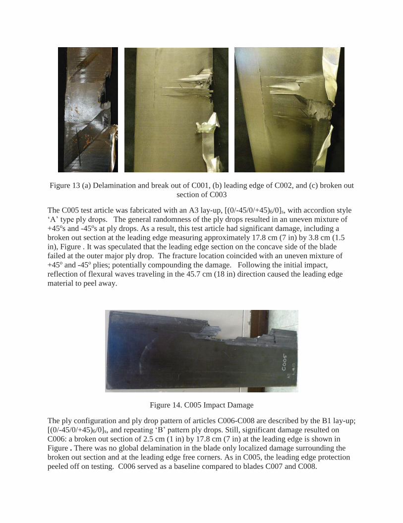
Figure 13 (a) Delamination and break out of C001, (b) leading edge of C002, and (c) broken out section of C003
The C005 test article was fabricated with an A3 lay-up, [(0/-45/0/+45)6/0]s, with accordion style ‘A’ type ply drops. The general randomness of the ply drops resulted in an uneven mixture of +45os and -45os at ply drops. As a result, this test article had significant damage, including a broken out section at the leading edge measuring approximately 17.8 cm (7 in) by 3.8 cm (1.5 in), Figure . It was speculated that the leading edge section on the concave side of the blade failed at the outer major ply drop. The fracture location coincided with an uneven mixture of +45o and -45o plies; potentially compounding the damage. Following the initial impact, reflection of flexural waves traveling in the 45.7 cm (18 in) direction caused the leading edge material to peel away.
Figure 14. C005 Impact Damage
The ply configuration and ply drop pattern of articles C006-C008 are described by the B1 lay-up; [(0/-45/0/+45)6/0]s, and repeating ‘B’ pattern ply drops. Still, significant damage resulted on C006: a broken out section of 2.5 cm (1 in) by 17.8 cm (7 in) at the leading edge is shown in Figure . There was no global delamination in the blade only localized damage surrounding the broken out section and at the leading edge free corners. As in C005, the leading edge protection peeled off on testing. C006 served as a baseline compared to blades C007 and C008.
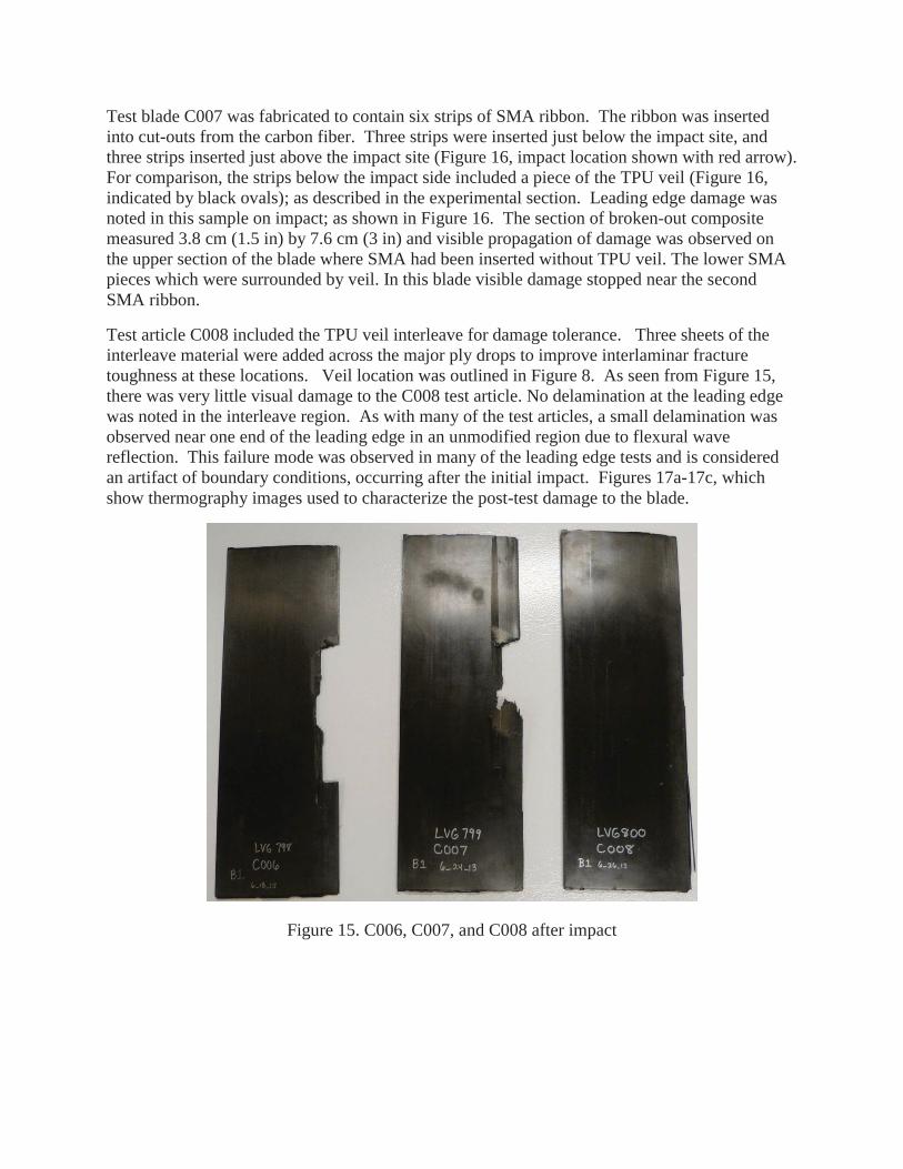
Test blade C007 was fabricated to contain six strips of SMA ribbon. The ribbon was inserted into cut-outs from the carbon fiber. Three strips were inserted just below the impact site, and three strips inserted just above the impact site (Figure 16, impact location shown with red arrow). For comparison, the strips below the impact side included a piece of the TPU veil (Figure 16, indicated by black ovals); as described in the experimental section. Leading edge damage was noted in this sample on impact; as shown in Figure 16. The section of broken-out composite measured 3.8 cm (1.5 in) by 7.6 cm (3 in) and visible propagation of damage was observed on the upper section of the blade where SMA had been inserted without TPU veil. The lower SMA pieces which were surrounded by veil. In this blade visible damage stopped near the second SMA ribbon.
Test article C008 included the TPU veil interleave for damage tolerance. Three sheets of the interleave material were added across the major ply drops to improve interlaminar fracture toughness at these locations. Veil location was outlined in Figure 8. As seen from Figure 15, there was very little visual damage to the C008 test article. No delamination at the leading edge was noted in the interleave region. As with many of the test articles, a small delamination was observed near one end of the leading edge in an unmodified region due to flexural wave reflection. This failure mode was observed in many of the leading edge tests and is considered an artifact of boundary conditions, occurring after the initial impact. Figures 17a-17c, which show thermography images used to characterize the post-test damage to the blade.
Figure 15. C006, C007, and C008 after impact
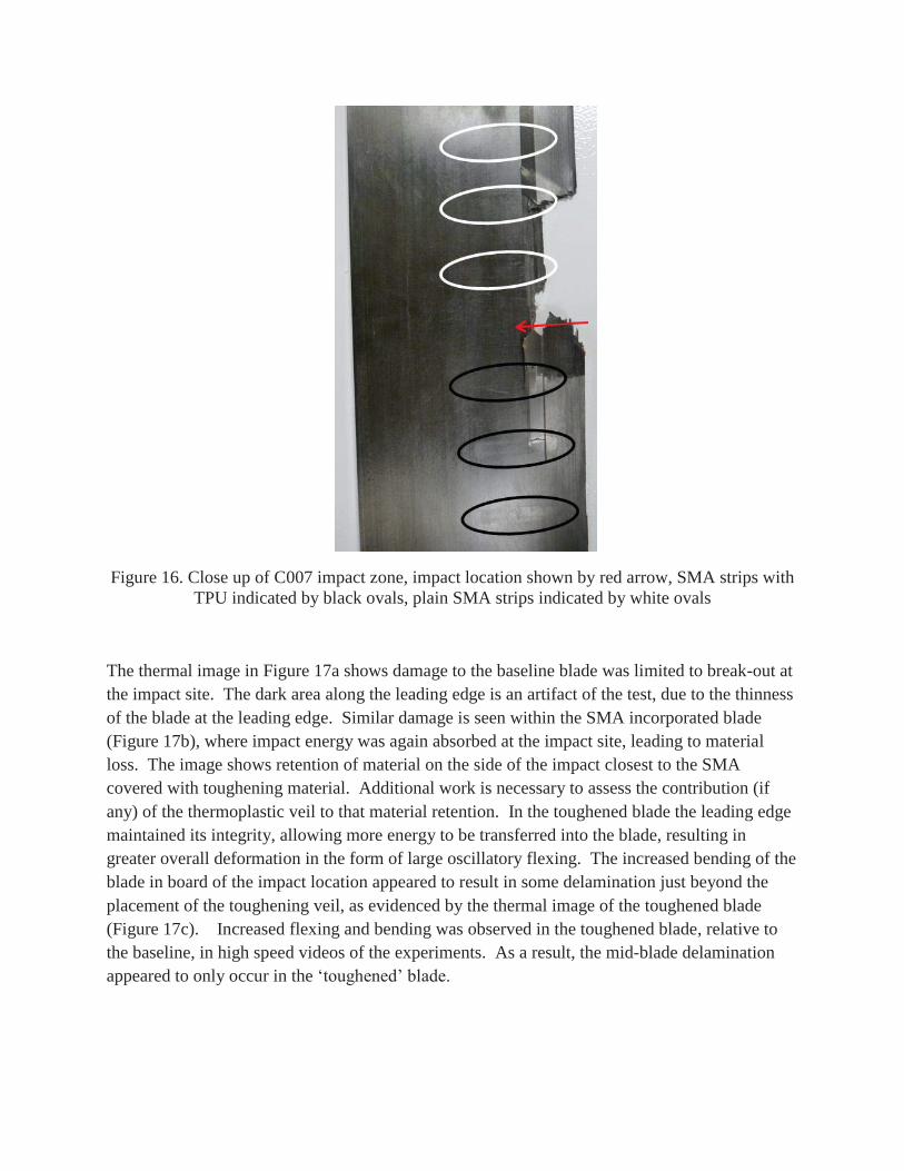
Figure 16. Close up of C007 impact zone, impact location shown by red arrow, SMA strips with TPU indicated by black ovals, plain SMA strips indicated by white ovals
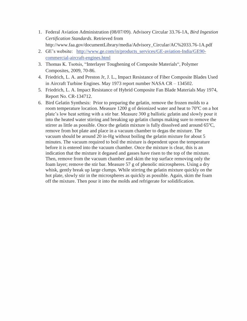
The thermal image in Figure 17a shows damage to the baseline blade was limited to break-out at the impact site. The dark area along the leading edge is an artifact of the test, due to the thinness of the blade at the leading edge. Similar damage is seen within the SMA incorporated blade (Figure 17b), where impact energy was again absorbed at the impact site, leading to material loss. The image shows retention of material on the side of the impact closest to the SMA covered with toughening material. Additional work is necessary to assess the contribution (if any) of the thermoplastic veil to that material retention. In the toughened blade the leading edge maintained its integrity, allowing more energy to be transferred into the blade, resulting in greater overall deformation in the form of large oscillatory flexing. The increased bending of the blade in board of the impact location appeared to result in some delamination just beyond the placement of the toughening veil, as evidenced by the thermal image of the toughened blade (Figure 17c). Increased flexing and bending was observed in the toughened blade, relative to the baseline, in high speed videos of the experiments. As a result, the mid-blade delamination appeared to only occur in the ‘toughened’ blade.
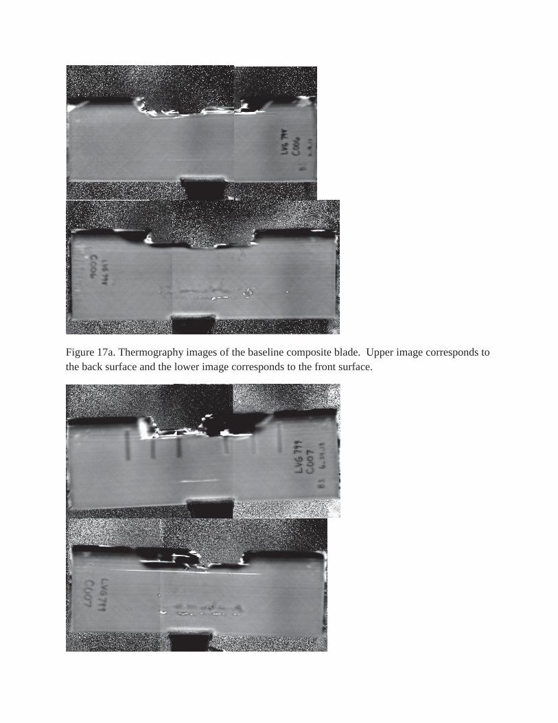
Figure 17a. Thermography images of the baseline composite blade. Upper image corresponds to the back surface and the lower image corresponds to the front surface.
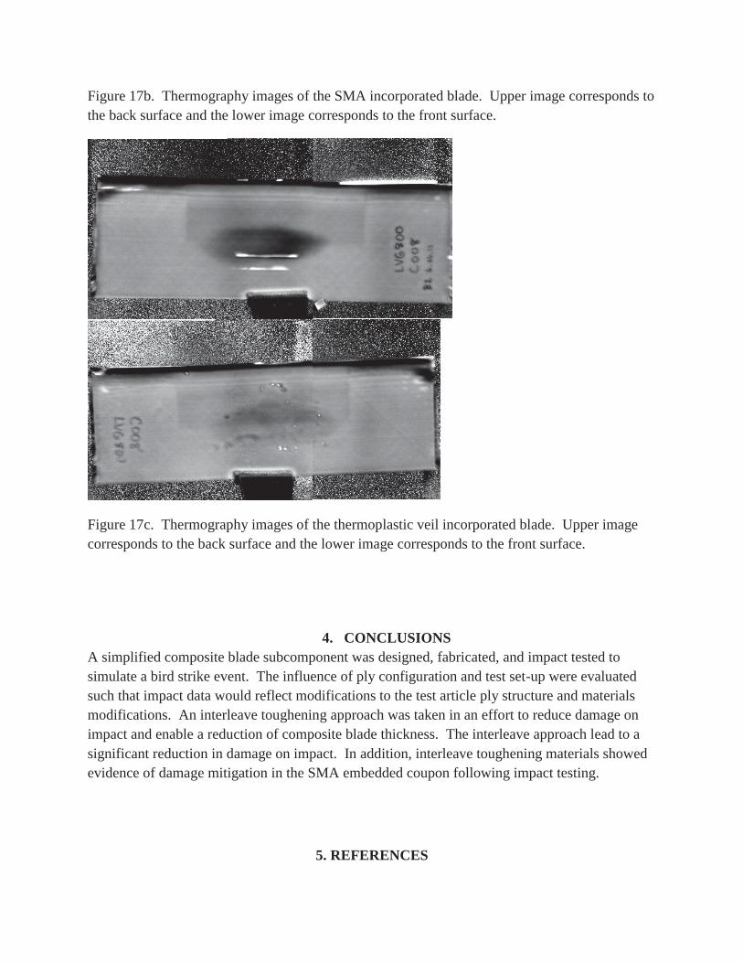
Figure 17b. Thermography images of the SMA incorporated blade. Upper image corresponds to the back surface and the lower image corresponds to the front surface.
Figure 17c. Thermography images of the thermoplastic veil incorporated blade. Upper image corresponds to the back surface and the lower image corresponds to the front surface.
4. CONCLUSIONS A simplified composite blade subcomponent was designed, fabricated, and impact tested to simulate a bird strike event. The influence of ply configuration and test set-up were evaluated such that impact data would reflect modifications to the test article ply structure and materials modifications. An interleave toughening approach was taken in an effort to reduce damage on impact and enable a reduction of composite blade thickness. The interleave approach lead to a significant reduction in damage on impact. In addition, interleave toughening materials showed evidence of damage mitigation in the SMA embedded coupon following impact testing.
5. REFERENCES
1. Federal Aviation Administration (08/07/09). Advisory Circular 33.76-1A, Bird Ingestion Certification Standards. Retrieved from http://www.faa.gov/documentLibrary/media/Advisory_Circular/AC%2033.76-1A.pdf
2. GE’s website: http://www.ge.com/in/products_services/GE-aviation-India/GE90-commercial-aircraft-engines.html
3. Thomas K. Tsotsis, “Interlayer Toughening of Composite Materials“, Polymer Composites, 2009, 70-86.
4. Friedrich, L. A. and Preston Jr, J. L., Impact Resistance of Fiber Composite Blades Used in Aircraft Turbine Engines. May 1973 report number NASA CR – 134502.
5. Friedrich, L. A. Impact Resistance of Hybrid Composite Fan Blade Materials May 1974, Report No. CR-134712.
6. Bird Gelatin Synthesis: Prior to preparing the gelatin, remove the frozen molds to a room temperature location. Measure 1200 g of deionized water and heat to 70oC on a hot plate’s low heat setting with a stir bar. Measure 300 g ballistic gelatin and slowly pour it into the heated water stirring and breaking up gelatin clumps making sure to remove the stirrer as little as possible. Once the gelatin mixture is fully dissolved and around 65oC, remove from hot plate and place in a vacuum chamber to degas the mixture. The vacuum should be around 20 in-Hg without boiling the gelatin mixture for about 5 minutes. The vacuum required to boil the mixture is dependent upon the temperature before it is entered into the vacuum chamber. Once the mixture is clear, this is an indication that the mixture it degased and gasses have risen to the top of the mixture. Then, remove from the vacuum chamber and skim the top surface removing only the foam layer; remove the stir bar. Measure 57 g of phenolic microspheres. Using a dry whisk, gently break up large clumps. While stirring the gelatin mixture quickly on the hot plate, slowly stir in the microspheres as quickly as possible. Again, skim the foam off the mixture. Then pour it into the molds and refrigerate for solidification.