Embed Size (px)
DESCRIPTION
Geothermal materials selection guide
Citation preview
i -.1I111
c?
t
I. L- L -J
ALO-3904-1 y-=
MATERIALS SELECTION GUIDELINES FOR GEOTHERMAL POWER SYSTEMS
First Edition
BY David W. DeBerry ,
Peter. F. Ellis Colin C. Thomas
September 1978
Work Performed Under Contract No. EG-77-GO43904
Radian Corporation Austin, Texas
U a S a DEPARTMENT OF ENERGY - Geothermal Energy
..
DISCLAIMER
This report was prepared as an account of work sponsored by an agency of the United States Government. Neither the United States Government nor any agency Thereof, nor any of their employees, makes any warranty, express or implied, or assumes any legal liability or responsibility for the accuracy, completeness, or usefulness of any information, apparatus, product, or process disclosed, or represents that its use would not infringe privately owned rights. Reference herein to any specific commercial product, process, or service by trade name, trademark, manufacturer, or otherwise does not necessarily constitute or imply its endorsement, recommendation, or favoring by the United States Government or any agency thereof. The views and opinions of authors expressed herein do not necessarily state or reflect those of the United States Government or any agency thereof.

DISCLAIMER Portions of this document may be illegible in electronic image products. Images are produced from the best available original document.
NOTICE
This report was prepared as an account of work sponsored by the United States Government. Neither the United States nor the United States Department of Energy, nor any of their employees, nor any of their contractors, subcontractors, or their employees, makes any warranty, express or implied, or assumes any legal liability or responsibility for the accuracy, completeness or usefulness of any information, apparatus, product or process disclosed, or represents that its use would not infringe privately owned rights.
This report has been reproduced directly from the best available copy.
Available from the National Technical Information Service, U. S. Department of Commerce, Springfield, Virginia 22161.
Price: Paper Copy $1 1.75 Microfiche $3.00
ALO-3904-1 Distribution Category UC66d
DCN# 78- 200- 181-
FIRST EDITION
MATERIALS SELECTION GUIDELINES FOR GEOTHERMAL POWER SYSTEM
By : David W. DeBerry Peter F. E l l i s Colin C. Thomas
Radian Program Manager: Marshall F. Conover
September, 1978
Radian Corporation 8500 Shoal Creek
Austin, Texas 78766
Contract No. EG-77-C-04-3904
DOE Program Manager: D r . Robert R. Reeber Division of Geothermal Energy
Prepared For: United S ta t e s Department of Energy
Energy Technology Washington, D.C. 20545
TABLE OF CONTENTS
Page 1.0 INTRODUCTION ..................................... 1-1
1.1 Background and Purpose ...................... 1-1
1 . 3 Summary and Overview ........................ 1-4
1 . 2 Scope ....................................... 1 - 3
2.0
3.0
GEOTHERMAL POWER CYCLES .......................... 2 - 1 2 . 1 Description of Nine Power Cycles ............ 2 - 1 2 . 2
2.3
Effect of Geothermal Fluid Properties on the Applicability of Power Cycles ............... 2 - 4 Effect of Fluid Properties on Materials
2-24 'Performance in Specific Process Streams ..... 2 . 3 . 1 Dual Flashed Steam Cycle ............. 2-25 2.3.2 Direct Binary Cycle 2-28 2 . 3 . 3 Flashed Steam Binary Cycle ........... 2-29
..................
CHEMICAL COMPOSITION OF GEOTHERMAL FLUIDS FROM A CORROSION STANDPOINT ............................. 3-1 3 . 1 Key Corrosive Chemical Species .............. 3 - 1 3 . 2 Key Corrosive Chemical Species in Selected
KGRA's ...................................... 3-5
4 . 0 RESULTS OF CORROSION TESTS IN GEOTHERMAL FLUIDS .. 4-1
KGRA's ...................................... 4 - 2 4 .1 Corrosion Tests at U.S. Liquid-Dominated
4.1.1 Most Corrosive: Salton Sea .......... 4 - 3 4 . 1 . 2 Moderately Corrosive: Baca. East
Mesa. Heber. Mono-Long Valley. Raft River ................................ 4 - 3
4 .1 .3 Least Corrosive: Beowawe ............ 4-5
Caldera) New Mexico KG RA .................... 4-11 4 . 2 . 1 Test Conditions ...................... 4-11
4.2 Results of Corrosion Tests at Baca (Valles
4 . 2 . 2 Results .............................. 4-15
ii
TABLE . OF CONTENTS (Continued)
5 . 0
4 . 3 Results of Corrosion Tests at East Mesa. California KGRA ............................. 4-20 4 . 3 . 1 Description of Test Streams .......... 4-20 4.3.2 Laboratory Tests ..................... 4-27 4 . 3 . 3 Field Tests .......................... 4-30
California KGRA ............................. 4-38 4.4.1 Test Conditions ...................... 4-38 4 .4 .2 Results .............................. 4-38
4.4 Results of Corrosion Tests at Heber.
4 . 5 Results of Corrosion Tests at Raft River. Idaho KGRA .................................. 4-43 4 . 5 . 1 Results of Coupon Tests .............. 4-43
Exchanger Materials .................. 4 - 5 1
California KGRA ............................. 4-52
Synthetic Fluids ..................... 4-52
4.5.2 Results of Tests of Potential Heat
4 .6 Results of Corrosion Tests in Salton Sea.
4 . 6 . 1 ‘Results of Laboratory Tests Using
4 . 6 . 2 Results of Field Tests at Well Magmamax No . 1 ....................... 4-72
CORROSION MODES FOR METALS IN GEOTHERMAL SYSTEMS . 5 - 1 5 . 1 Mild and Low Alloy Steels ................... 5-5
5 . 1 . 1 General Guidelines for Using Mild
5 . 1 . 2
5 . 1 . 3 Stres Corrosion Cracking of Low Alloy
5 . 1 . 4
5.1.5
5.2.1 General Guidelines for Use of Stain-
Steels ............................... 5-5 Uniform and Localized Corrosion of Mild Steels .......................... 5-9
.............................. 5-24
Middle Alloy Steels .................. 5-24
Hydrogen Blistering of Mild Steels ... 5 - 3 2 5 .2 Stainless Steels ............................ 5 - 3 3
less Steels .......................... 5 - 3 3
Sulfide Stress Cracking of Low and
i i i
TABLE OF CONTENTS (Continued)
Pa= - 5.2.2 Corrosion Resistance of Major
5.2.3
5.2.4 Stress Corrosion Cracking of Stain-
5.2..5 Intergranular Corrosion of Stainless
5.2.6 Sulfide Stress Cracking of Stainless
Classes of Stainless Steels .......... 5-35 Pitting and Crevice Corrosion of Stainless Steels ..................... 5-36
less Steels .......................... 5-44
Steels. .............................. 5-49
Steels ............................... 5-51 5.3 Titanium and Titanium Alloys ................ 5-51
5.3.1 Uniform Corrosion of Titani um........ 5-52 5.3.2 Pitting and Crevice Corrosion of
Titani ................................ 5-52 5.3.3 Galvanic Coupling and Other Pre-
cautions ............................. 5-56 5.3.4 Stress Corrosion Cracking of Titanium-
5.4 Nickel-Based Alloys ......................... 5-59
Cr-Mo Alloys ......................... 5-59
Based Alloys ......................... 5-57
5.4.1 General Corrosion Resistance of Ni-
5.4.2 Stress Corrosion Cracking of Nickel-
5.4.3 Sulfide Stress Cracking and Hydrogen
5.4.4 Intergranular Corrosion of Nickel-
Based Alloys ......................... 5-59
Embrittlement ........................ 5-60
Based Alloys ......................... 5-60 5.5 Copper-Based Alloys ......................... 5-61 5.6 Applicability of Other Metallic Materials ... 5-62
5.6.2 Zirconium and Tantal urn............... 5-63
5.7 Condensate .................................. 5-64 5.8 Steam from Liquid-Dominated Geothermal
5.6.1 Cobalt Alloys ........................ 5-62
5.6.3 Aluminum Alloys ...................... 5-63
Sources......... ............................ 5-65
i v
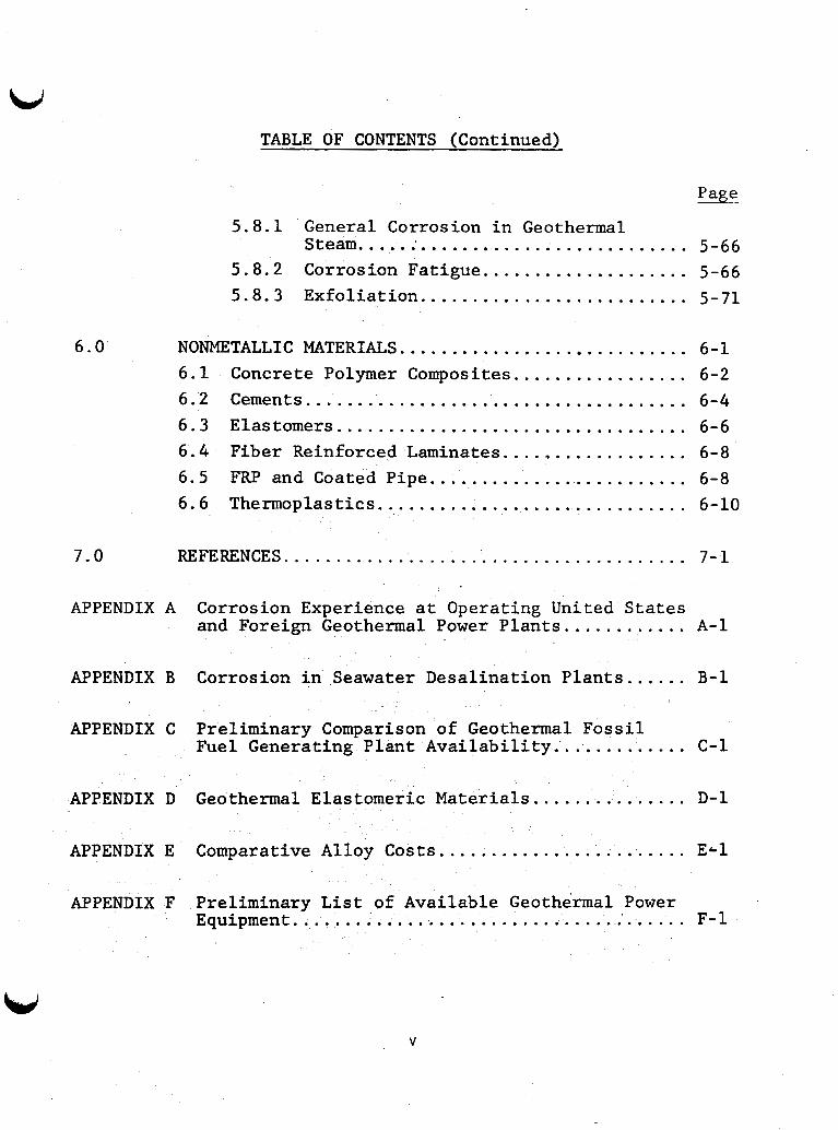
TABLE OF CONTENTS (Continued)
Page
5.8.1 General Corrosion in Geothermal Steam ................................ 5-66
5.8.2 Corrosion Fatigue .................... 5-66 5.8.3 Exfoliation .......................... 5-71
6.0 NONMETALLIC MATERIALS ............................ 6-1 6.1 Concrete Polymer Composites ................. 6-2 6.2 Cements ..................................... 6-4 6.3 Elastomers .................................. 6-6 6.4 Fiber Reinforced Laminates .................. 6-8 6.5 FRP and Coated Pipe ......................... 6-8 6.6 Thermoplastics .............................. 6-10
7.0 REFERENCES ....................................... 7-1
APPENDIX A Corrosion Experience at Operating United States and Foreign Geothermal Power Plants ............ A-1
APPENDIX B Corrosion in Seawater Desalination Plants ...... B-1
APPENDIX C
APPENDIX D
APPENDIX E
APPENDIX F
Preliminary Comparison of Geothermal Fossil Fuel Generating Plant Availability ............. C-1
Geothermal Elastomeric Materials ............... D-1
Comparative Alloy Costs ........................ Ecl
Preliminary List of Available Geothermal Power Equipment ....................................... F-1
V
LIST OF TABLES Page
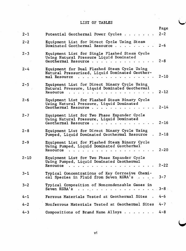
Potent ia l Geothermal Power Cycles . . . . . . . 2-2
Equipment L i s t f o r Direct Cycle Using Steam Dominated Geothermal Resource . . . . . . . . . 2 - 6
2 - 1
2-2
Equipment L i s t f o r Single Flashed Steam Cycle Using Natural Pressure Liquid Dominated Geothermal Resource . . . . . . . . . . . . . . 2 - 8
2 - 3
2 - 4 Equipment fo r Dual Flashed Steam Cycle Using Natural Pressurized, Liquid Dominated Geother- m a l Resource . . . . . . . . . . . . . . . . . 2-10
2-5 Equipment L i s t f o r Direct Binary Cycle Using Natural Pressure, Liquid Dominated Geothermal Resource . . . . . . . . . . . . . . . . . . . 2-12
2 -6 Equipment L i s t f o r Flashed Steam Binary Cycle Using Natural Pressure, Liquid Dominated Geothermal Resource . . . . . . . . . . . . . . 2 - 1 4
Equipment L i s t f o r Two Phase Expander Cycle Using Natural Pressure, Liquid Dominated Geothermal Resource . . . . . . . . . . . . . .
2-7
2-16
2 -18 Equipment L i s t f o r Direct Binary Cycle Using Pumped, Liquid Dominated Geothermal Resource .
2 - 8
2 - 9 Equipment L i s t f o r Flashed Steam Binary Cycle Using Pumped, Liquid Dominated Geathermal Resource . . . . . . . . . . . . . . . . . . . 2-20
2-10 Equipment L i s t f o r Two Phase Expander Cycle Using Pumped, Liquid Dominated Geothermal Resource . . . . . . . . . . . . . . . . . . . 2-22
3 - 1 Typical Concentrations of Key Corrosive Chemi- c a l Species i n Fluid from Seven KGRA's . . . . 3-7
3-2 Typical Composition of Noncondensable Gases i n Seven KGRA's . . . . . . . . . . . . . . . . . . 3-8
4-6
4- 7
4-8
4-1
4-2
4- 3
Ferrous Materials Tested a t Geothermal Sites . Nonferrous Materials Tested a t Geothermal Sites
Compositions of Brand Name Alloys . . . . . . .
v i
U
4-4
4-5
4-6
4- 7
4-8
4-9
4-10
4- 11
4- 12
4-13
4- 14
4- 15
4-16
4-17
4-18
LIST OF TABLES (CONT'D) Page
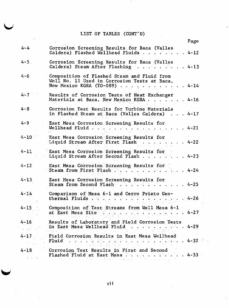
Corrosion Screening Results f o r Baca (Valles
Corrosion Screening Results f o r Baca (Valles
Composition of Flashed Steam and Fluid from W e l l N o . 11 Used i n Corrosion Tests a t Baca,
Results of Corrosion Tests of Heat Exchanger Materials a t Baca, New Mexico KGRA . . . . . . . 4-16
Caldera) Flashed Wellhead Fluids . . . . . . . . 4-12
Caldera) Steam After Flashing . . . . . . . . . 4-13
New Mexico KGRA (TO-089) . . . . . . . . . . . . 4-14
Corrosion T e s t Results f o r Turbine Materials i n Flashed Steam a t Baca (Valles Caldera) . . . 4-17 E a s t Mesa Corrosion Screening Results fo r
E a s t Mesa Corrosion Screening Results f o r
East Mesa Corrosion Screening Results f o r
East Mesa Corrosion Screening Results f o r
East Mesa Corrosi Screening Results f o r
Comparison of Mesa 6-1 and Cerro Pr ie to Geo-
Composition of Test Streams from Well Mesa 6-1
Results of Laboratory and Field Corrosion T e s t s
Field Corrosion Results i n E a s t Mesa Wellhead
Wellhead Fluid . . . . . . . . . . . . . . . . . 4-21
Liquid Stream After F i r s t Flash . . . . . . . . 4-22
Liquid S t r eam After Second Flash 4-23
Steam from F i r s t Flash . . . . . . . . . . . . . 4-24
Steam from Second Flash . . . . . . . . . . . . 4-25
thermal Fluids . . . . . . . . . . . . . . . . . 4-26
a t East Mesa S i t e . . . . . . . . . . . . . . . 4-27
i n East Mesa Wellhead Fluid . . . . . . . . . . 4-29
Fluid . . . . . . . . . . . . . . . . . . . 4-32
. . . . . . . .
Corrosion T e s t Results in F i r s t and Second Flashed Fluid a t East Mesa . . . . . . . . . . . 4-33
v i i
4- 19
4-20
4-21
4-22
4-23
4-24
4-25
4-26
4-27
4-28
4-29
4-30
4-31
4- 32
4-33
LIST OF TABLES (CONT'D) Page
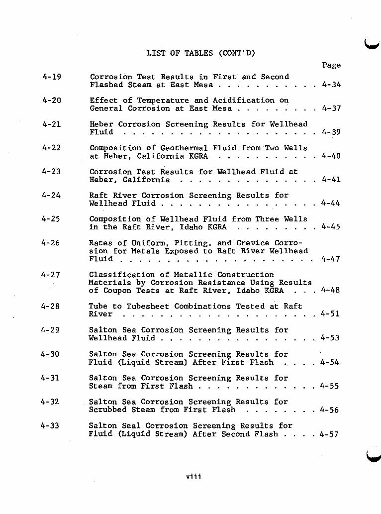
Corrosion T e s t Results i n F i r s t and Second Flashed Steam a t E a s t Mesa . . . . . . . . . . . 4-34
Effect of Temperature and Acidification on General Corrosion at E a s t Mesa . . . . . . . . . 4-37
Heber Corrosion Screening Results f o r Wellhead Fluid . . . . . . . . . . . . . . . . . . . . . 4-39
Composition of Geothermal Fluid from Two Wells a t Heber, California KGRA . . . . . . . . . . . 4-40
Corrosion T e s t Results f o r Wellhead Fluid a t Heber, Cal i fornia . . . . . . . . . . . . . . . 4-41
R a f t River Corrosion Screening Results f o r Wellhead Fluid . . . . . . . . . . . . . . . . . 4-44
Composition of Wellhead Fluid from Three Wells i n the Raft River, Idaho KGRA . . . . . . . . . 4-45
Rates of Uniform, P i t t i n g , and Crevice Corro- s ion f o r Metals Exposed t o Raft River Wellhead F l u i d . . . . . . . . . . . . . . . . . . . . . 4-47
Class i f ica t ion of Metal l ic Construction Materials by Corrosion Resistance Using Results of Coupon T e s t s a t Raft River, Idaho KGRA . . . 4-48
Tube t o Tubesheet Combinations Tested a t Raft River . . . . . . . . . . . . . . . . . . . . . 4-51
Salton Sea Corrosion Screening Results f o r Wellhead Fluid . . . . . . . . . . . . . . . . . 4-53
Salton Sea Corrosion Screening Results f o r Fluid (Liquid Stream) After F i r s t Flash . . . . 4-54
Salton Sea Corrosion Screening Results f o r Steam from F i r s t Flash . . . . . . . . . . . . . 4-55
Salton Sea Corrosion Screening Results f o r Scrubbed Steam from F i r s t Flash . . . . . . . . 4-56
Salton Seal Corrosion Screening Results f o r Fluid (Liquid Stream) A f t e r Second Flash . . . . 4-57
v i i i
4- 34
4- 35
4- 36
4-37
4-38
4- 39
4-40
4-41
4- 42
4- 43
4-44
4-45
4-46
LIST OF TABLES (CONT'D) Page
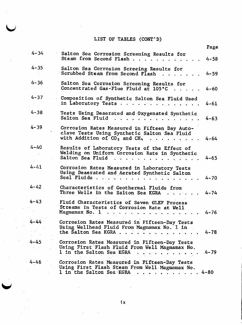
Salton Sea Corrosion Screening Results f o r Steam from Second Flash . . . . . . . . . . . . 4-58
Salton Sea Corrosion Screeing Results f o r Scrubbed Steam from Second Flash . . . . . . . 4-59
Salton Sea Corrosion Screening Results f o r
Composition of Synthetic Salton Sea Fluid Used
Tests Using Deaerated and Oxygenated Synthetic
Concentrated Gas-Flue Fluid a t 105°C . . . . . 4-60
i n Laboratory T e s t s . . . . . . . . . . . . . . 4-61
Salton Sea Fluid . . . . . . . . . . . . . . . 4-63
Corrosion Rates Measured i n Fif teen Day Auto- clave Tests Using Synthetic Salton Sea Fluid with Addition of COn and CHs . . . . . . . . . 4-64
Results of Laboratory T e s t s of the Effect of Welding on Uniform Corrosion R a t e i n Synthetic Salton Sea Fluid . . . . . . . . . . . . . . . 4-65
Corrosion Rates Measured i n Laboratory Tests Using Deaerated and .Aerated Synthetic Salton Seal Fluids 4-70
Character is t ics of Geothermal Fluids from
. . . . . . . . . . . . . . . . . .
Three Wells i n the Salton Sea KGRA . . . . . . 4-74
Magmamax No. 1 . . . . . . . . . . . . . . . . 4-76 Fluid Character is t ics of Seven GLEF Process Streams i n T e s t s of Corrosion R a t e a t W e l l
Corrosion Rates Measured i n Fifteen-Day T e s t s Using Wellhead Fluid From Magmamax No. 1 i n
Corrosion Rates Measured i n Fifteen-Day Tests Using F i r s t Flash Fluid From W e l l Magmamax No. 1 i n the Salton Sea KGRA . . . . . . . . . . . 4-79
Corrosion Rates Measured i n Fifteen-Day T e s t s Using F i r s t Flash Steam From Well Magmamax No.
t h e Salton Sea KGRA . . . . . . . . . . . . . . 4-78
1 i n the Salton Sea KGRA . . . . . . . . . . . 4-80
i x
4-47
4-48
4-49
4- 50
4-51
4-52
5 -1
5-2
5-3
5 - 4
5-5
5-6
5-7
6-1
LIST OF TABLES (CONT'D)
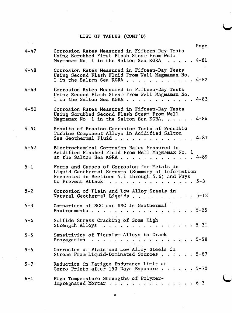
Page Corrosion Rates Measured in Fifteen-Day Tests Using Scrubbed First Flash Steam From Well Magmamax No. 1 in the Salton Sea KGRA . . . . . 4 - 8 1
Corrosion Rates Measured in Fifteen-Day Tests Using Second Flash Fluid From Well Magmamax No. 1 in the Salton Sea KGRA . . . . . . . . . . . . 4-82
Corrosion Rates Measured in Fifteen-Day Tests Using Second Flash Steam From Well Magmamax No. 1 in the Salton Sea KGRA . . . . . . . . . . . . 4-83
Corrosion Rates Measured in Fifteen-Day Tests Using Scrubbed Second Flash Steam From Well Magmamax No. 1 in the Salton Sea KGRA. . . . . . 4 - 8 4
Results of Erosion-Corrosion T e s t s of Possible Turbine Component Alloys in Acidified Salton Sea Geothermal Fluid . . . . . . . . . . . . . . 4-87
Electrochemical Corrosion Rates Measured in Acidified Flashed Fluid From Well Magmamax No. 1 at the Salton Sea KGRA . . . . . . . . . . . . . 4-89
Forms and Causes of Corrosion for Metals in Liquid Geothermal Streams (Summary of Information Presented in Sections 5 . 1 through 5 . 6 ) and Ways to Prevent Attack . . . . . . . . . . . . . . . 5 - 3
Corrosion of Plain and Low Alloy Steels in Natural Geothermal Liquids . . . . . . . . . . . 5-12
Comparison of SCC and SSC in Geothermal Environments . . . . . . . . . . . . . . . . . . 5-25
Sulfide Stress Cracking of Some High
Sensitivity of Titanium Alloys to Crack Progagation . . . . . . . . . . . . . . . . . . 5-58
Corrosion of Plain and Low Alloy Steels in Stream From Liquid-Dominated Sources . . . . . . 5-67
Strength Alloys . . . . . . . . . . . . . . . . 5 - 3 1
Reduction in Fatigue Endurance Limit at Cerro Prieto after 150 Days Exposure . . . . . . 5-70
High Temperature Strengths of Polymer- Impregnated Mortar . . . . . . . . . . . . . . . 6-3
X
LIST OF TABLES (CONT'D)
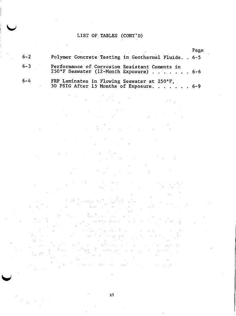
Page 6-2
6-3
Polymer Concrete Testing in Geothermal Fluids. . 6-5 Performance of Corrosion Resistant Cements in 250°F Seawater (12-Month Exposure) . . . . . . . 6-6 FRP Laminates in Flowing Seawater at 250"F, 30 PSIG After 15 Months of Exposure. . . . . . . 6-9
6-4
x i
1 I
bi LIST OF FIGURES !
2-1
2-2
2- 3
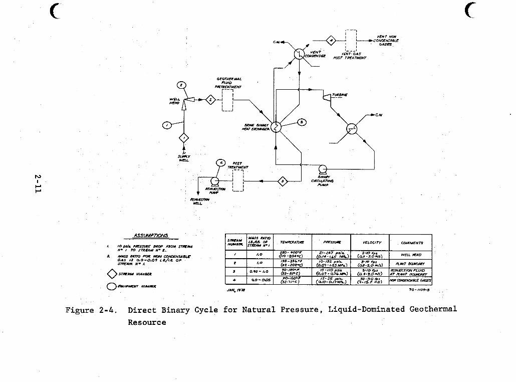
2-4
2-5
2-6
2-7
2-8
2-9
4- 1
5-1
5-2
5-3
5-4
5-5
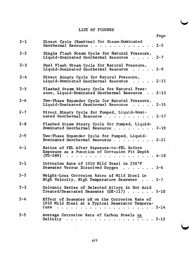
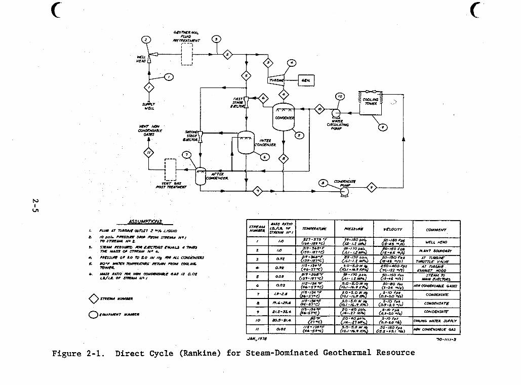
Page Direct Cycle (Rankine) f o r Steam-Dominated Geothermal Resource . . . . . . . . . . . . . . 2-5
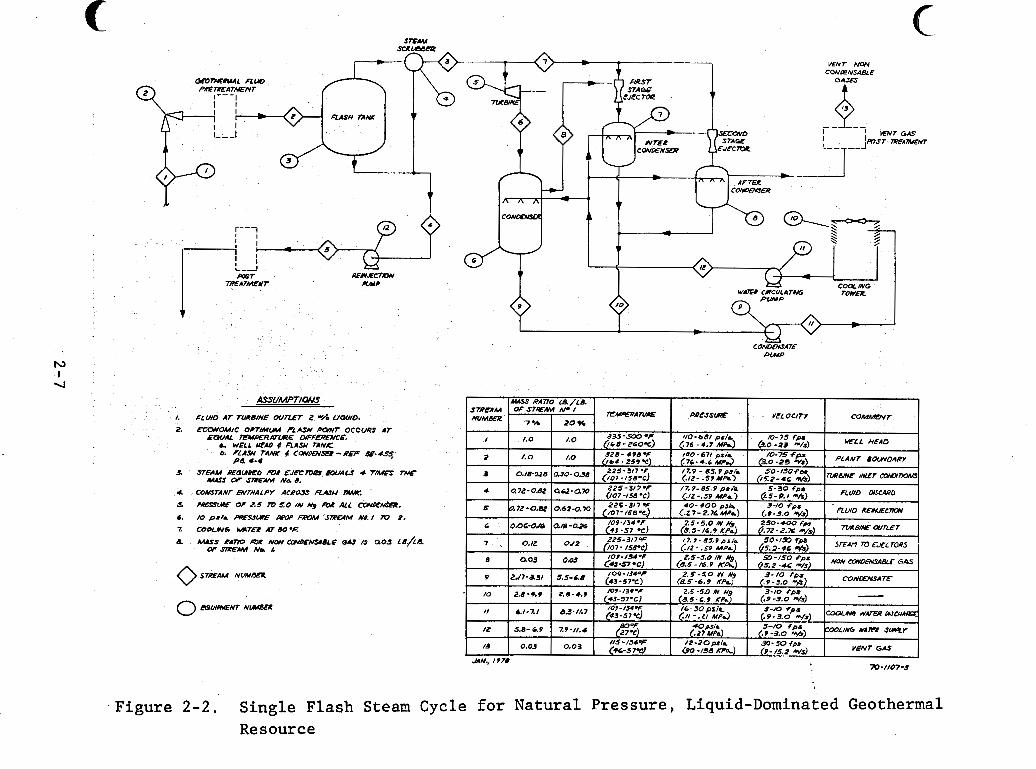
1 1 Single Flash Steam Cycle f o r Natural Pressure,
. . . . . Liquid-Dominated Geothermal Resource 2-7 I Dual Flash Steam Cycle f o r Natural Pressure, i Liquid-Dominated Geothermal Resource 2-9
Direct Binary Cycle f o r Natural Pressure , Liquid-Dominated Geothermal Resource . . . . . 2-11
i . . . . . t
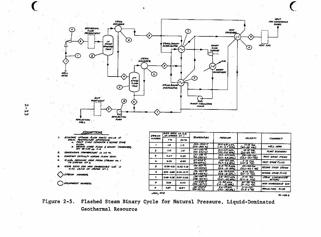
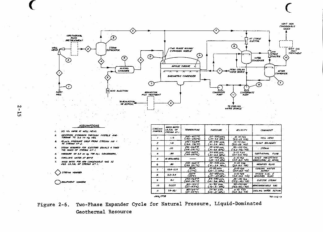
Flashed Steam Binary Cycle f o r Natural Pres- sure , Liquid-Dominated Geothermal Resource . . 2-13 Two-Phase Expander Cycle f o r Natural Pressure , Liquid-Dominated Geothermal Resource . . . . . 2-15
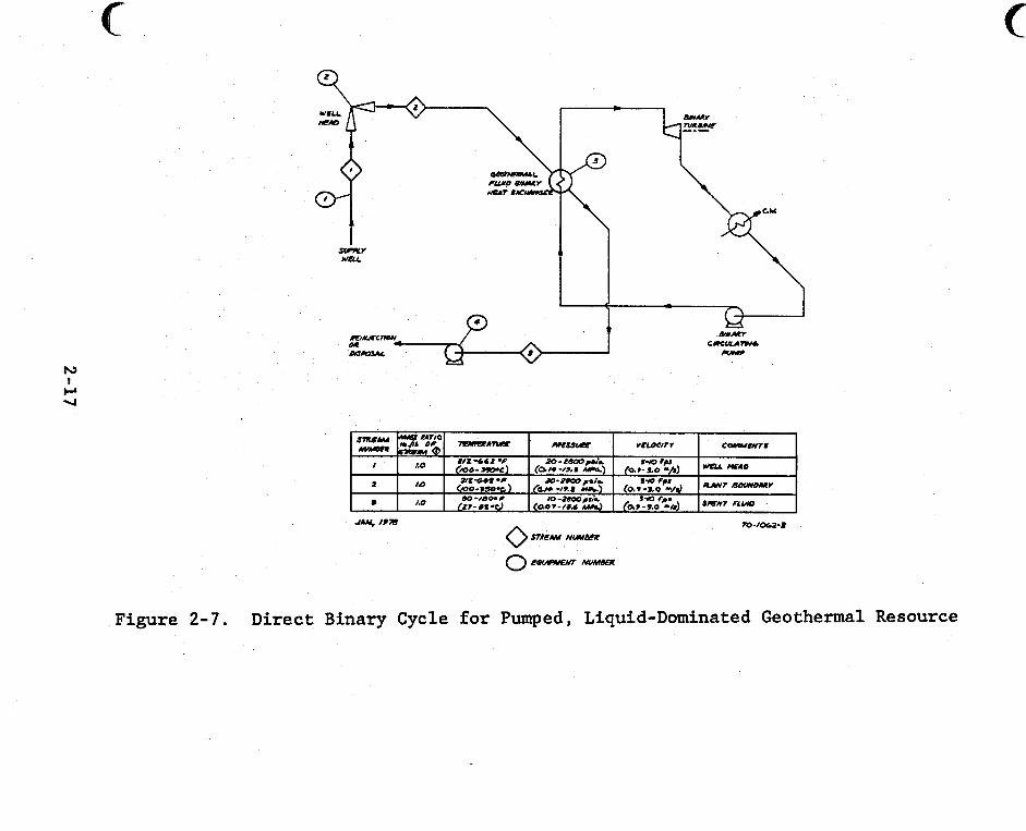
Direct Binary Cycle f o r Pumped, Liquid-Domi- nated Geothermal Resource . . . . . . . . . . . 2-17
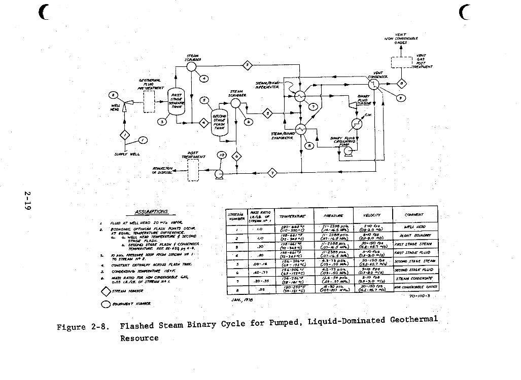
Flashed Steam Binary Cycle f o r Pumped, Liquid- Dominated Geothermal Resource . . . . . . . . . 2-19 Two-Phase Expander Cycle f o r Pumped, Liquid- Dominated Geothermal Resource . . . . . . . . . 2 -2 1
Ratios of FEL A f t e r Exposure-to-FEL Before Exposure as a Function of Corrosion P i t Depth (TO-089) . . . . . . . . . . . . . . . . . . . 4-18
Corrosion Rate of 1010 Mild Steel i n 250°F Seawater Versus Dissolved Oxygen . . . . . . . 5-6
t Weight-Loss Corrosion Rates of Mild Steel in High Velocity, High Temperature Seawater . . . 5-7
Galvanic Series of Selected Alloys i n Hot Acid Treated/Deaerated Seawater (GE-117) . . . . . . 5-10 Effect of Seawater pH on t h e Corrosion Rate of 1010 Mild Steel at a Typical Deaerator Tempera- t u r e . . . . . . . . . . . . . . . . . . . . . 5-14
Average Corrosion R a t e of Carbon Steels vs _.
Sa l in i ty . . . . . . . . . . . . . . . . . . . 5-15
x i i
5-6
5-7
5-8
5-9
5-10
5-11
5-12
5-13
5-14
5-15
5-16
LIST OF FIGURES (CONT'D) Page
P i t t i n g and Corrosion Potent ia ls of Steel i n Oxygen-Free Chloride Solutions 25°C . . . . 5-17
Corrosion R a t e of A212B Carbon Steel i n Deaerated 4 M - N a C l as a Function of pH and Temperature . . . . . . . . . . . . . . . . . 5-19
P i t t i n g and Corrosion Potent ia ls of Steel as a Function of Temperature i n Heber Geother- m a l Fluid . . . . . . . . . . . . . . . . . . 5-21
Approximate Correlation of Hardness, Time t o Fai lure and Applied Stress f o r Carbon Steels
Approximate Correlation of Failure Time f o r Carbon Steels i n 5% N a C l Containing Various Concentrations of H2S . . . . . . . . . . . . 5-27
(3000 ppm H 2 S i n 5% NaC1) . . . . . . 5-27
Yield Strength-Threshold Stress Relationship f o r Low Alloy Stee ls . . . . . . . . . . . . . 5-28
Effect of Chloride Ion Act ivi ty on Steady- State Cri t ical Poten t ia l f o r P i t t i n g , 2 5 ° C . . . . . . . . . . . . . . . . . . . . . 5-36
P i t t i n g Potent ia l s and Corrosion Potent ia l s of Types 304 and 316 Sta in less Steel i n 4 M, N a C l as a Function of Temperature . . . . . . 5-38
Comparison of the Cri t ical P i t t i n g Potent ia l s of Fe-Cr-Mo Alloys with Several Commercial Alloys in Deaerated Synthetic Seawater a t 9O"C,
Relationship Between the Cri t ical P i t t i n g Potent ia l s (EcSCr Measured i n Deaerated Syn- t h e t i c Seawater a t 9O"C, pH = 7.2k0.2) of Fe-Cr-Mo Based Alloys and Their Resistance t o Crevice Attack A f t e r a 14-Day Exposure t o Synthetic Seawater a t 1 2 1 ° C and ~ 6 0 ppm
Effect of Chloride and Oxygen on Time t o Cracking Type 204 Sta in less Steel Wire Held a t Constant Load i n Single Phase Aqueous Environ- m e n t . . . . . . . . . . . . . . . . . . . . . 5-44
pH = 7.2k0.2 . . . . . . . . . . . . . . . . 5-41
Oxygen . . . . . . . . . . . . . . . . . . . . 5 -42
x i i i
LIST OF FIGURES (CONT'D) Page
5-17 Effect of pH, Chloride Content, and Tempera- tu re on the Stress Corrosion Cracking of Type 304 Stainless Steel Under Residual Weld Stresses . . . . . . . . . . . . . . . . . . . 5-45
5-18 Anticipated Corrosion Performance of Unalloyed Titanium (ASTM Grade 2) i n Chloride Brines and Under N a C l Solid S a l t Deposits . . . . . . . . . . . . . . . . . . . 5-52
5-19 Effect of Temperature and pH on Crevice Corrosion of Unalloyed Titanium (GR.2) i n Saturated N a C l Brine . . . . . . . . . . . . . 5-53
5-20 Effect of Temperature and pH on Crevice Corrosion of Ticode-12 (Gr. 12) i n Saturated N a C l Brine . . . . . . . . . . . . . . . . . . 5-54
x i v
~
'bi
! ,
1
i I ~
I
1
1
i i I
1 i
I
i
i I i
I 1
i I
W
1.0 INTRODUCTION
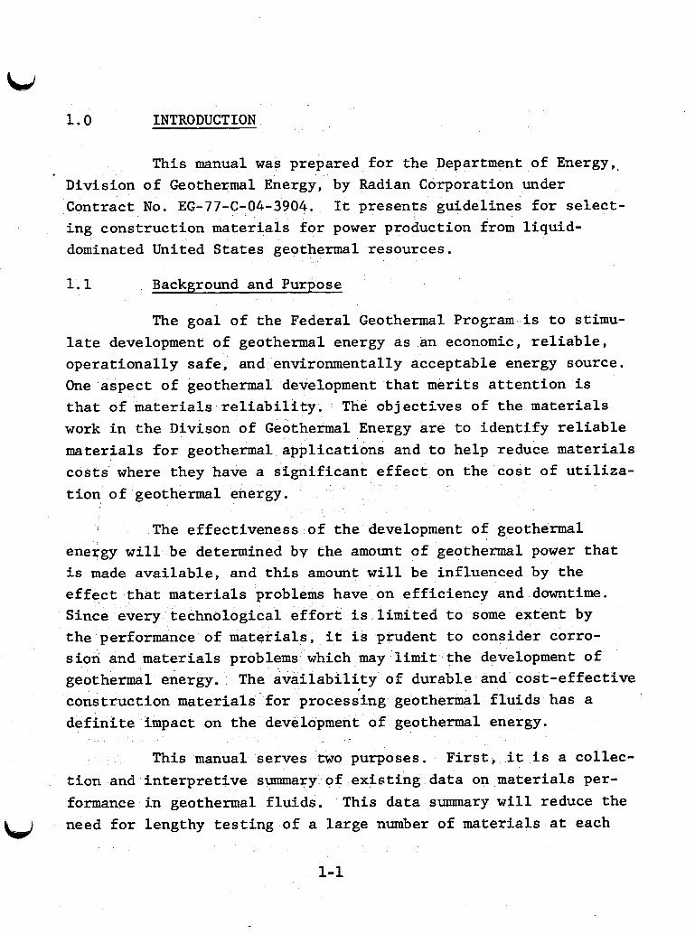
This manual was prepared for the Department of Energy,. Division of Geothermal Energy, by Radian Corporation under Contract No. EG-77-C-04-3904. It presents guidelines for select- ing construction materials for power production from liquid- dominated United States geothermal resources.
1.1 Background and Purpose
The goal of the Federal Geothermal Program is to stimu- late development of geothermal energy as an economic, reliable, operationally safe, and environmentally acceptable energy source. One aspect of geothermal development that merits attention is that of materials reliability. work in the Divison of Geothermal Energy are to identify reliable materials for geothermal applications and to help reduce materials costs where they have a significant effect on the cost of utiliza- tion of geothermal energy.
The objectives of the materials
The effectiveness of the development of geothermal energy will be determined by the amount of geothermal power that is made available, and this amount will be influenced by the effect that materials problems have on efficiency and downtime. Since every technological effort is limited to some extent by the performance of materials, it is prudent to consider corro- sion and materials problems which may limit the development of geothermal energy. construction materials for processing geothermal fluids has a definite impact on the development of geothermal energy.
The av ilability of durable and cost-effective
This manual serves two purposes. First, it is a collec- tion and interpretive summary of existing data on materials per- formance in geothermal fluids. need for lengthy testing of a large number of materials at each
This data summary will reduce the
1-1
new geothermal site. It provides a way to help screen potential construction materials through past experience.
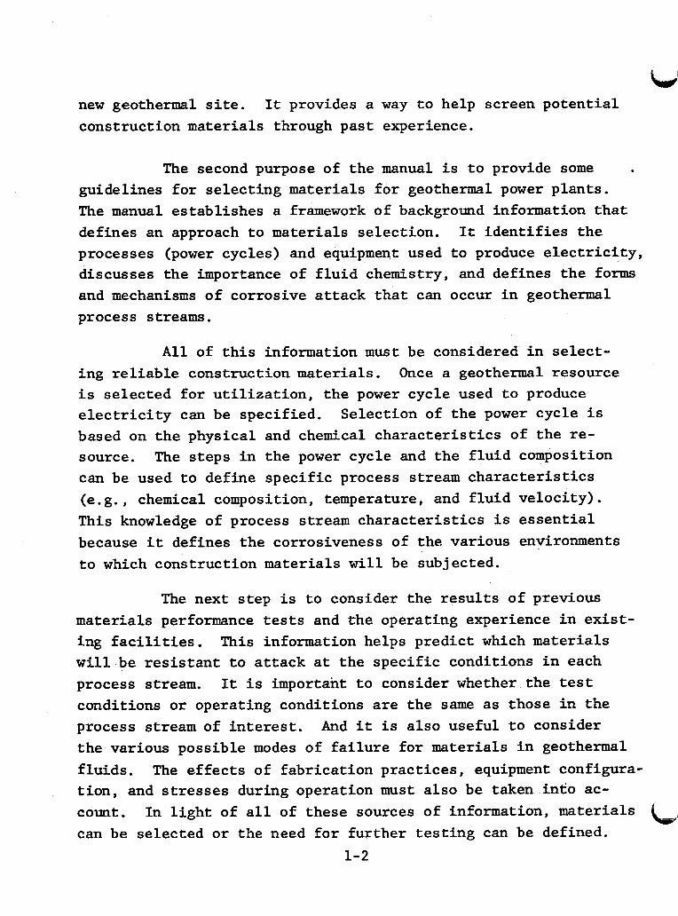
The second purpose of the manual is to provide some guidelines for selecting materials for geothermal power plants. The manual establishes a framework of background information that defines an approach to materials selection. processes (power cycles) and equipment used to produce electricity, discusses the importance of fluid chemistry, and defines the forms and mechanisms of corrosive attack that can occur in geothermal process streams.
It identifies the
A l l of this information must be considered in select- ing reliable construction materials. is selected for utilization, the power cycle used to produce electricity can be specified. based on the physical and chemical characteristics of the re- source. can be used to define specific process stream characteristics (e.g., chemical composition, temperature, and fluid velocity). This knowledge of process stream characteristics is essential because it defines the corrosiveness of the various environments to which construction materials will be subjected.
Once a geothermal resource
Selection of the power cycle is
The steps in the power cycle and the fluid composition
The next step is to consider the results of previous materials performance tests and the operating experience in exist- ing facilities. will be resistant to attack at the specific conditions in each process stream. conditions or operating conditions are the same as those in the process stream of interest. the various possible modes of failure for materials in geothermal fluids. The effects of fabrication practices, equipment configura- tion, and stresses during operation must also be taken into ac- count. can be selected or the need for further testing can be defined.
This information helps predict which materials
It is important to consider whether the test
And it is also useful to consider
In light of all of these sources of information, materials
1-2
Most corrosion failures are due to well known phenomena. Minimizing these failures often depends upon knowing the environ- ment to which the materials are exposed and being aware of past materials experience. Close cooperation is required between cor- rosion and design engineers. characteristics of the geothermal resource, the power cycle to be applied, the durability of potential materials under these con- ditions, and the economics of these materials. Materials consi- derations and concern begin during the design phase but should continue through plant construction, start-up, and operation.
Attention must be given to the
1.2 Scope
Geothermal resources include steam-dominated sources, liquid dominated sources, geopressurized sources, and dry (hot rock) sources. There are numerous geothermal resource areas in the United States. resource areas (KGRA's) with potential for the extraction of thermal or electrical energy. This manual considers materials performance in liquid-dominated U . S . resources with sufficient temperatures to be useful for electric power generation. are seven such liquid-dominated KGRA's for which fluid chemistry is adequately de€ined. fluids from these resources can be made based on the fluid characteristics. performance tests have been ne using fluids from five of the seven KGRA's: Baca, New Mexico; East Mesa, California; Heber, California; Raft River, Idaho; and Salton Sea, California. Test data available for Heber and Baca are rather limited, but Raft River, Salton Sea, and East Mesa have been studied in more detail.
Some have been designated as known geothermal
There
Predictions about the corrosiveness of
Corrosion rates have been measured and materials
Other useful data on materials performance have been accumulated in saline fluids and operating geothermal power plants. Materials performance data are available for seawater distillation L 4
1-3
plants, foreign operating power plants (Cerro Prieto, Mexico and Wairakei, New Zealand) and The Geysers, a power plant utilizing a steam-dominated resource. The information is useful in select- ing construction materials for liquid-dominated resources and is included in the Appendix.
The manual summarizes currently available information in a format which allows new information to be added as it be- comes available. The manual can be updated in the future by incorporating the results of further testing or data for other KGRA' s .
1.3 Summarv and Overview
The information in this manual is presented in six sections and six appendices. Section 2 defines and diagrams nine potential power cycles for the generation of electricity from geothermal fluids. One power cycle is applicable to steam- dominated resources, five are for liquid-dominated sources re- covered by natural pressure, and three are for liquid-dominated sources recovered by pumping. General fluid properties that influence the applicability of power cycles to a particular geo- thermal resource are discussed. process streams in power cycles is described based on variations in chemical composition and temperature.
The corrosivity of individual
Results of materials performance tests are analyzed based on the chemical composition of the corrosive medium and physical factors such as temperature, duration of exposure, and fluid velocity. to use test results to predict materials performance in other systems. Geothermal fluids are complex, variable mixtures whose characterization is difficult but essential. Section 3 identi- fies the key chemical components in geothermal fluids that are
These variables must be well defined in order
1- 4
significant in determining corrosivity. ponents in seven United States liquid-dominated KGEU's are defined.
The key chemical com-
Section 4 gives both summarized and detailed results of materials performance tests in U.S. liquid-dominated resources. The seven KGRA's treated in Section 3 are classified according to relative corrosiveness. Detailed results of corrosion rate mea- surements are given for Baca, East Mesa, Heber, Raft River, and Salton Sea KGRA's in two formats. table which serves as a guide to the test results. results in the screening tables are classified according to detec- tion and severity of attack. summaries and discussions of the corrosion rate measurements. The results in Section 4 summarize available test results, but they should be used cautiously. Test conditions, test duration, and completeness of the tests should be considered in applying the results.
The first format is a "screening" Corrosion
The second format includes detailed
Currently available test data are mostly the result of uniform and localized corrosion rate measurements. But there are other kinds of corrosive attack for metals in geothermal fluids. Section 5 describes the various forms and mechanisms of corrosive attack that can occur in geothermal process streams. These generalizations are especially useful when materials must be specified for conditions at which tests have not been done. If the corrosion rate of a material has been tested at the stream conditions of interest, the information in this section is still useful. It explains how fabrication practices, equipment con- figuration, and operating stresses influence materials perfor- mance. attack that have not been studied in tests will be important.
And it can be used to predict whether other forms of ~
1-5
j Section 6 discusses the application of nonmetallic
materials in geothermal environments. Information on the be- havior of nonmetallics in these systems is limited.
The appendices contain information on (1) operating experience at geothermal power plants, (2) corrosion in desalina- tion facilities, (3) reliability of geothermal plants, ( 4 ) elas- tomeric materials, ( 5 ) comparative alloy costs, and (6) geother- mal equipment manufacturers. erating geothermal power plants is particularly important to de- signers of future facilities. failures and problem areas that may not be encountered in short- term corrosion tests.
The corrosion experience from op-
Operating experience points out
i
1-6
2.0 GEOTHERMAL POWER CYCLES
A thermodynamic power cycle is the process employed to extract and utilize geothermal energy to produce electricity. The methods used in the power cycle to produce steam or other vapor to drive a turbine depend on the characteristics of the geothermal fluid. The four general types of geothermal re- sources found in the United States are steam-dominated, liquid- dominated, hot dry rocks, and geopressured resources. Na- tional interest in electrical generation is focused on the first two types of resources, and it is these resources for which typ- ical power cycles are described.
This section of the manual defines nine potential power cycles: one for steam-dominated sources, five for liquid- dominated sources recovered by natural pressure, and three for liquid-dominated sources recovered by pumping. The three pumped source power cycles are the same as those for sources recovered ~y natural pressure except for the pumping equipment. Elow diagrams, heat balances, and process stream conditions are presented as well as a list of major equipment items for each power cycle. General fluid properties that influence the ap- plicability of power cycles to a ,particular geothermal resource are discussed. Finally, three power cycles are considered in detail. The corrosivity of individual process streams is des- cribed based on variations in chemical composition and tempera-
Process
ture. ,
2.1 Description of Nine Power Cycles
Nine generalized power cycles are potentially appli- cable to steam- and liquid-dominated geothermal resources. They
2-1
r
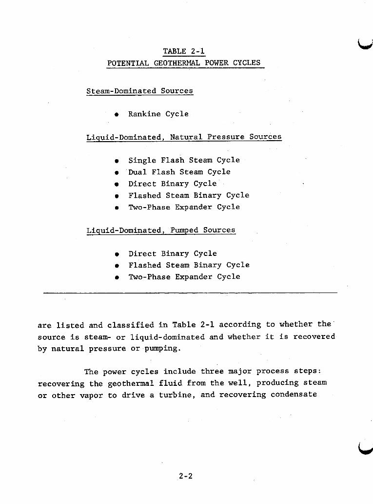
TABLE 2 - 1
POTENTIAL GEOTHERMAL POWER CYCLES
Steam-Dominated Sources
0 Rankine Cycle
Liquid-Dominated, Natural Pressure Sources
0 Single Flash Steam Cycle 0 Dual Flash Steam Cycle e Direct Binary Cycle 0 Flashed Steam Binary Cycle 0 Two-Phase Expander Cycle
Liquid-Dominated, Pumped Sources
0 Direct Binary Cycle 0 Flashed Steam Binary Cycle 0 Two-Phase Expander Cycle
are listed and classified in Table 2-1 according to whether the’ source is steam- or liquid-dominated and whether it is recovered by natural pressure or pumping.
The power cycles include three major process steps: recovering the geothermal fluid from the well, producing steam or other vapor to drive a turbine, and recovering condensate
2-2
and noncondensable gases. Power cycles differ mainly in the methods used to generate steam or other vapor to drive the tur- bine. The Rankine Cycle uses steam directly from steam-dom- inated sources. Single and dual flash cycles employ a change in pressure to separate steam from a liquid-dominated source. Binary cycles use a second liquid as an intermediate heat trans- fer medium. In direct binary cycles, vapor to drive the turbine is produced from the second liquid by heat exchange with the geothermal fluid. In flashed steam binary cycles steam is sep- arated from the geothermal fluid and used to vaporize the sec- ond liquid. Two-phase expander cycles use a mixture of both va- por and liquid from the geothermal fluid to drive the turbine.
Power cycles are also classified based on the method Liquid-dom- of recovering the geothermal fluid from the well.
inated resources can be recovered either by natural pressure or by a downhole pump. vantage that little hardware is required down the borehole, re- ducing the cost and complexity of equipment installation and maintenance. Downhole pumping can be used to increase well pro- duction, keep noncondensable gases dissolved, and prevent uncon- trolled chemical changes in the well head fluid caused by flash- ing during the recovery process. The economic advantage of higher well flow rates from pumping may offset the cost of in- stallation and maintenance of downhole pumps.
Recovery by natural pressure has the ad-
Figures 2-1 through 2-9 are process flow sheets for the nine power cycles listed in Table 2-1. These diagrams show the primary flow paths, major equipment items, geothermal fluid .
mass per unit of fluid introduced into the cycle, bulk fluid temperature and pressure, and the anticipated bulk velocity of the fluid in each stream.
2-3
Heat balances were calculated using steam table Val- Heat balances and geothermal fluid con- ues and ideal cycles.
centrations for a specific plant design may therefore differ from the range of values given in the flow sheets. ences arise because of the deviation of geothermal fluid thermo- dynamic data from the pure water thermodynamic data of the steam tables and the irreversibilities associated with each piece of equipment. ances are noted on each flow sheet.
The differ-
Other assumptions used in calculating the heat bal-
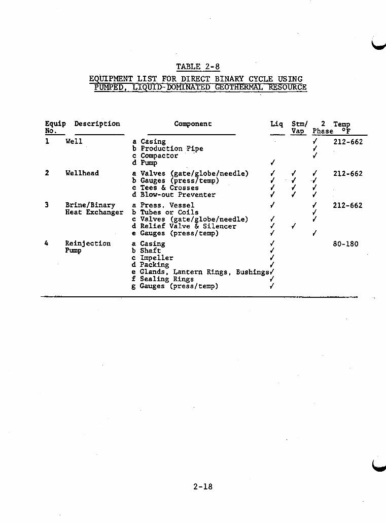
An equipment list (Tables 2-2 through 2-10) has been formulated for each of the nine potential power cycles. equipment item number corresponds to the circled number on the flow sheet for the respective power cycle. The major compon- ents within each equipment item have been listed with the asso- ciated bulk temperature and geothermal fluid phase in contact with the equipment. Local geothermal fluid velocities within a piece of equipment may differ significantly from the bulk geo- thermal fluid velocity indicated on the flow sheets. The local velocity must be used for material selection purposes and for design of materials compatibility experiments. Because compo- nents of a major piece of equipment will probably be of dis- similar materials, they are listed separately under each equip- men t it em.
The
The equipment lists are not intended to be all encom- passing and do not include every equipment item which may be used. However, equipment types and operating conditions can be selected from the lists which closely correspond to equipment for material selection or material compatability test programs. For instance, lube oil and hydrogen coolers are similar in ser- vice to the conditions found in condensers.
2-4
2 -5
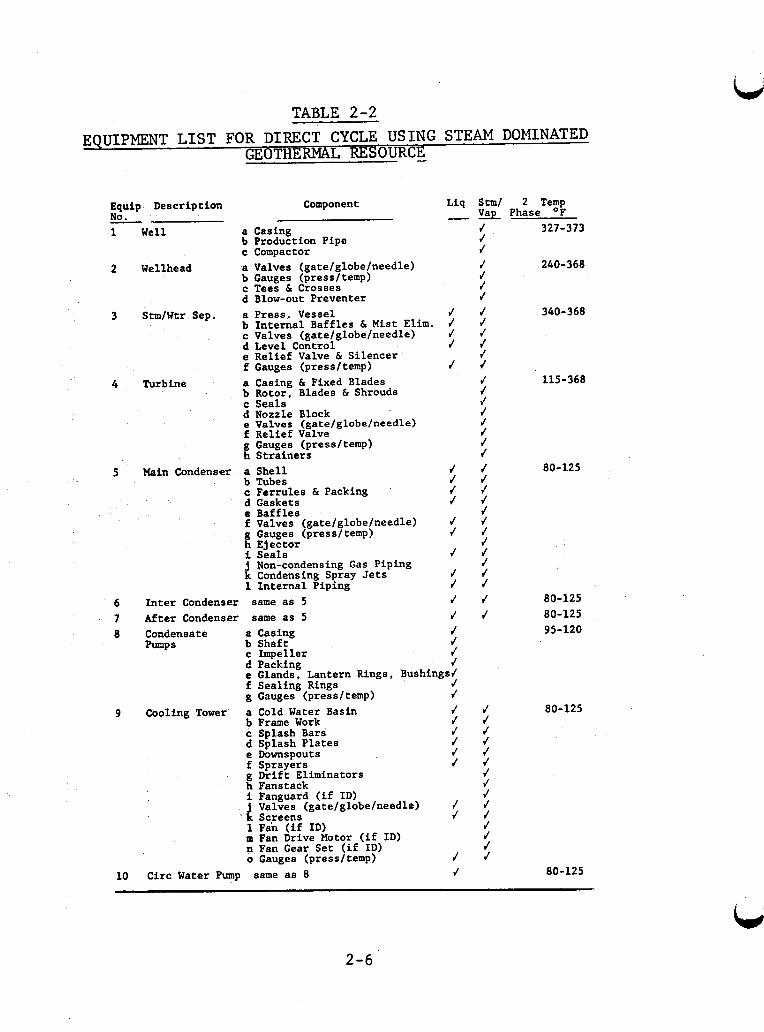
TABLE 2-2
EQUIPMENT L I S T FOR DIRECT CYCLE USING STEAM DOMINATED GEOTHERMAL RES OURCE -
Well
Wellhead
3
4
stmfwtr Sep.
Turbine
Equip Description NO. -
5
10
Component
a Casing b Production Pipe c Compactor a Valves (gate/globe/needle) b Gauges (press/temp) c Tees C Crosses d Blow-out Preventer a Press. Vessel b Internal Baffles C Mist Elim. c Valves (gate/globe/needle) d Level Control e Relief Valve C Silencer f Gauges (pressltemp) a Casing C Fixed Blades b Rotor, Blades 6 Shrouds c Seals d Nozzle Block e Valves (gate/globe/needle) f Relief Valve g Gauges (press/temp) h Strainers
Main Condenser a Shell b Tubes c Ferrules C Packing '
d Gaskets e Baffles f Valves (gatefglobefneedle) g Gauges (press/temp) h Ejector
i Condensing Spray Jets 1 Internal Piping
Nan-condensing Gas Piping
Inter Condenser same as 5 After Condenser same as 5 Condensate a Casing Pumps b Shaft
c Imueller d Pakking e Glands. Lantern Rings, Bushings; f Sealing Rings J g Gauges (pressftemp) J
-
J J J J
J
J J J J
J J
f
J J J J J J J J
Liq Stm/ 2 Temp & Phase OF
80-125
80-125 80-125 95-120
J 327-373 J J J 240-368 J f J J 340-368 J J J J J J 115-368 J J J J J J J f J J J J J f J J J J J f J
Cooling Tower a Cold Water Basin J b Frame Work J c Splash Bars J d Splash Plates J e Downspouts J f Sprayers J g Drift Eliminators h Fanstack i Fanguard (if ID) j Valves (gate/globe/needle) 4
1 Fan (if ID) m Fan Drive Motor (if ID) n Fan Gear Set (if ID)
k Screens J
o Gauges (pressltemp) J Circ Water Pump same as 8 J
J 80-125 J J J J J J J J J J J J J J
80-125
2-6
c
;i
2. fCCWOMlC OP7fMuU RASH POlNT OCCURS A T
L WELL UEAO # FLAW TAN<. 6. FLAyl TANK # CCWDENSR - R€F M-4q
Pb 4-4
Ko(ML F M ~ A T U Z E OfFFEW?XG.
c VENT NON
CONENSABLE G A B A
w-ffo7-s A N , I??.
Figure 2-2. Single Flash Steam Cycle for Natural Pressure, Liquid-Dominated Geothermal Re source
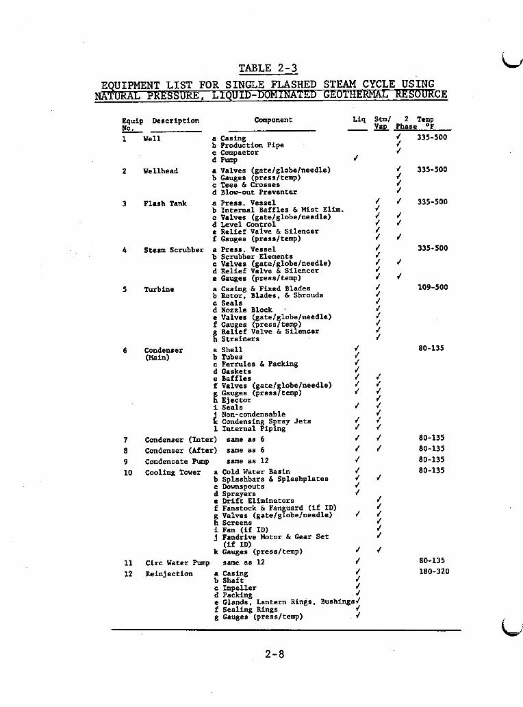
TABLE 2-3
I
I
EQUIPMENT L I S T FOR SINGLE FLASHED STEAM CYCLE USING TURAL PRESSURE, LIQUID - D O M I ~ D G-CE
Equip Description Component Liq S t m l 2 Temp Phase OF No. -
7
1
2
3
4
5
6
7 8 9 10
11 12
C d e f
Well a Casing b Production Pipe c Compactor d Pump
Wellhead a Valves (gatefglobefneedle) b Gauges (pressltemp) c Tees & Crosses d Blow-out Preventer
Flash Tank a Press. Vessel b Internal Baffles & Mist Elim. Valves (gatelglobelneedle) Level Con rol Relief Vaive 6 Silencer Gauges (pressltemp)
Steam Scrubber a b
d e
C
Turbine a b C d e f
f Condenser a
b (Main)
d C
e f
i j k 1
Condenser (Inter) Condenser (After) Condensate Pump Cooling Tower a
b
d e f g h i j
k
C
Circ Water Prrmp Reinjection a
b C d e
Press. Vessel Scrubber Elements Valves (gate/globe/needle) Relief Valve & Silencer Gauges (pressltemp) Casing & Fixed Blades Rotor. Blades, & Shrouds Seals Nozzle Block . Valves (gatelglobelneedle) Gauges (pressltemp) Relief Valve & Silencer Strainers Shell Tubes Ferrules & Packing Gaskets Baffles Valves (gate1 lobelneedle) Gauges (press$temp) Ejector Seals Non-condensable Condensing Spray Jets Internal Piping same as 6 same as 6 same as 12
Cold t?ater Basin Splashbars 6 Splashplates
Sprayers Drift Eliminators Fanstock 6 Fan uard (if ID) Valves (gatelgfobelneedle) Screens Fan (if ID) Fandrive Motor h Gear Set
Downspouts
(if ID) Gauges (pressltemp) same as 12 Casing Shaft Impeller
1 Packine
f
f f f f J f f
f
J f f J f f f J f
f
f J f f f / - Glands: Lantern Rings. Bushings? J f
f Sealing Rings g Gauges (pressftemp)
f f f f J f f f f f f f f f f f J f f
J f f f f f f f f f
f
J J f f f f
f
f f /
f f f f f
f f
f
f
4
335-500
335-500
335-500
335-500
109-500
80-135
80-135 80-135 80-135 80-135
80-135 180-320
2-8
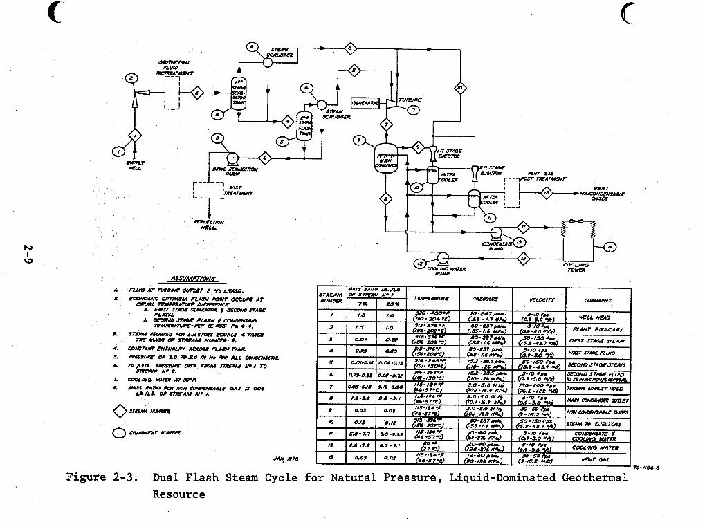
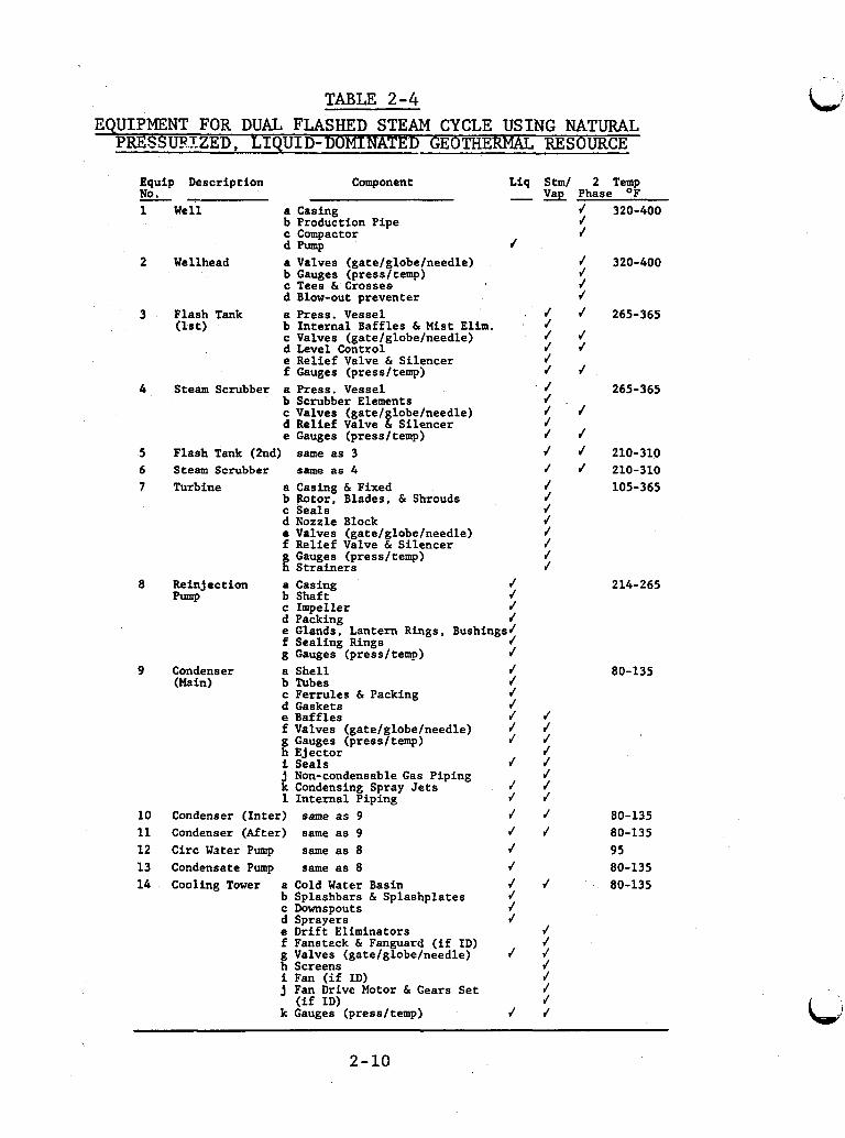
TABLE 2-4 EQUIPMENT FOR DUAL FLASHED STEAM CYCLE U S I N G NATURAL 1
Equip Description
Well a b
d We 1 lhead a
b
d Flash Tank a (1st) b
d
C
C
C
f Steam Scrubber a
b C d e
Flash Tank (2nd) Steam Scrubber Turbine a
b
d C
e f
Reinjection a b
d C
pump
9 Condenser (bin)
10 11 12 13 14
Component Liq Stm/ -vap
Casing Production Pipe Compactor
Valves (gate/globe/needle) Gauges (press/temp) Tees & Crosses Blow-out preventer
Internal Baffles & Mist Elim. Valves (gate/globe/needle) Level Control Relief Valve & Silencer
Pump J
Press. Vessel . J J J J J
Gauges (press/temp) J Press. Vessel J Scrubber Elements J
J 1'
Gauges (press/temp) J same as 3 J same as 4 r'
Valves (gate/globe/needle) Relief Valve & Silencer
Casing & Fixed Rotor, Blades, & Shrouds Seals Nozzle Block Valves (gate/globe/needle) Relief Valve & Silencer Gauges (pressltemp) Strainers Casing Shaft Inmeller
J J J
Pa'cking J
f Sealing Rings J g Gauges (press/temv) J a Shell J b Tubes J c Ferrules & Packing J d Gaskets J e Baffles J J f Valves (gate/ lobeheedle) $ $ g Gauges (pressftemp) h Ejector J i Seals J J j Non-condensable Gas Piping J k Condensing Spray Jets J J 1 Internal Piping J J
e Glands, Lantern Rings, Bushings/
Condenser (Inter) same as 9 J J Condenser (After) same as 9 Circ Water Pump same as 8
J J J
Condensate Pump same as 8 J Cooling Tower a Cold Water Basin
b Splashbars & Splashplates c Downspouts d Sprayers e Drift Eliminators f Fanstzck & Fanguard (if ID) g Valves (gate/globe/needle) h Screens i Fan (if ID)
J J J J J
J J
J J J J
2 Temp Phase OF
J 320-400 J J
/ 320-400 J J J J 265-365
J J
J 265-365
J
J J 210-310 f 210-310
105-365
214-265
80-135
80-135 80-135 95 80-135 80-135
j Fan Drive Motor 6 Gears Set (if ID) J
k Gauges (oress/temp) J J
J
2-10
4
I
2-11
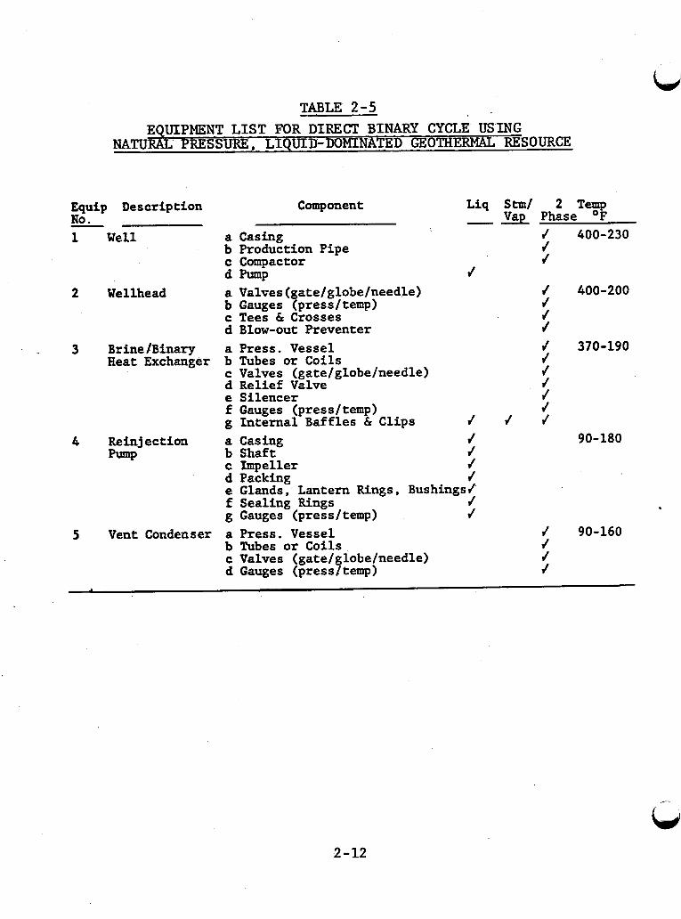
TABLE - 2-5 EQUIPMENT LIST FOR DIRECT BINARY CYCLE USING
NATURAL P RESSURE, LIQUID-DOMINATED GEOTHERMAL RESOURCE
Equip Description Component No.
3
Well a Casing b Production Pipe c Compactor
b Gauges (press/temp) c Tees & Crosses d Blow-out Preventer
d m P Wellhead a Valves(gate/globe/need
Liq Stm/ 2 Temp Vap Phase O F
J 400-230 J J
J 400-200 J J J
J
BrinelBinary a Press. Vessel J 370-190 Heat Exchanger b Tubes or Coils J
c Valves (gate/globe/needle) J d Relief Valve J e Silencer J f Gauges (press/temp) J g Internal Baffles & Clips J J J
b Shaft J c Impeller J d Packing J
f Sealing Rings J g Gauges (pressltemp) J
Reinjection a Casing f 90-180 pump
e Glands, Lantern Rings, Bushings/
Vent Condenser a Press. Vessel b Tubes or Coils c Valves (gate/globe/needle) d Gauges (press/ temp)
J 90-160 J J J
2-12
i I
Y
ti
d*
I) 0
0
U
2-13
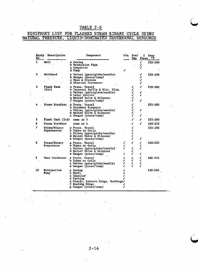
TABLE 2-6 EQUIPMENT LIST FOR FLASHED STEAM BINARY CYCLE USING
NATURAL PRESSURE, LIQUID-DOMINATED GEOTHERMAL RESOURCE
Equip Description Component Liq Stml 2 Temp - No. - & Phase OF
1
2
3
4
5 6 7
8
9
10
Well a Casing J b Production Pipe J c Compactor J d Pump f
Wellhead a Valves (gate1 lobetneedle) J
c Tees & Crosses J d Blow-out Preventer J
Flash Tank a Press. Vessel J J (1st) b Internal Baffle & Mist. Elim. J
c Valves (gate/globe/needle) J J d Level Control J J e Relief Valve & Silencer J f Gauges (pressltemp) J J
b Gauges (press$temp) J
Steam Scrubber a Press. Vessel b Scrubber Elements c Valves (gatelglobelneedle) d Relief Valve & Silencer e Gauges (pressltemp)
J J J J J J J
Flash Tank (2nd) same as 3 J f Steam Scrubber same as 4 J J SteamIBinary a Press. Vessel f Superheater b Tubes or Coils . J
c Valves (gate/globe/qeedle) J d Relief Valve & Silencer f e Gauges (pressltemp) J f
Steam/Binary a Press. Vessel / / / Evaporator b Tubes or Coils J J
c Valves (gate/globe/needle) J J J d Relief Valve & Silencer J e Gauges (pressltemp) J J J
Vent Condenser a Press. Vessel J J J b Tubes or Coils J J J c Valves (gate/globe/needle) J J J d Gauges (press/temp) J J J
Reinjection a Casing b Shaft c Impeller
e Glands, Lantern Rings, Bushings/ d Packing J
f Sealing Rings J g Gauges (pressltemp) J
230-500
230-500
230-500
225-380
225-380 160-225 225-380
160-225
160-225
130-250 .
2-14
I I
Figure 2-6. Two-Phase Expander Cycle for Natural Pressure, Liquid-Dominated Geothermal Resource
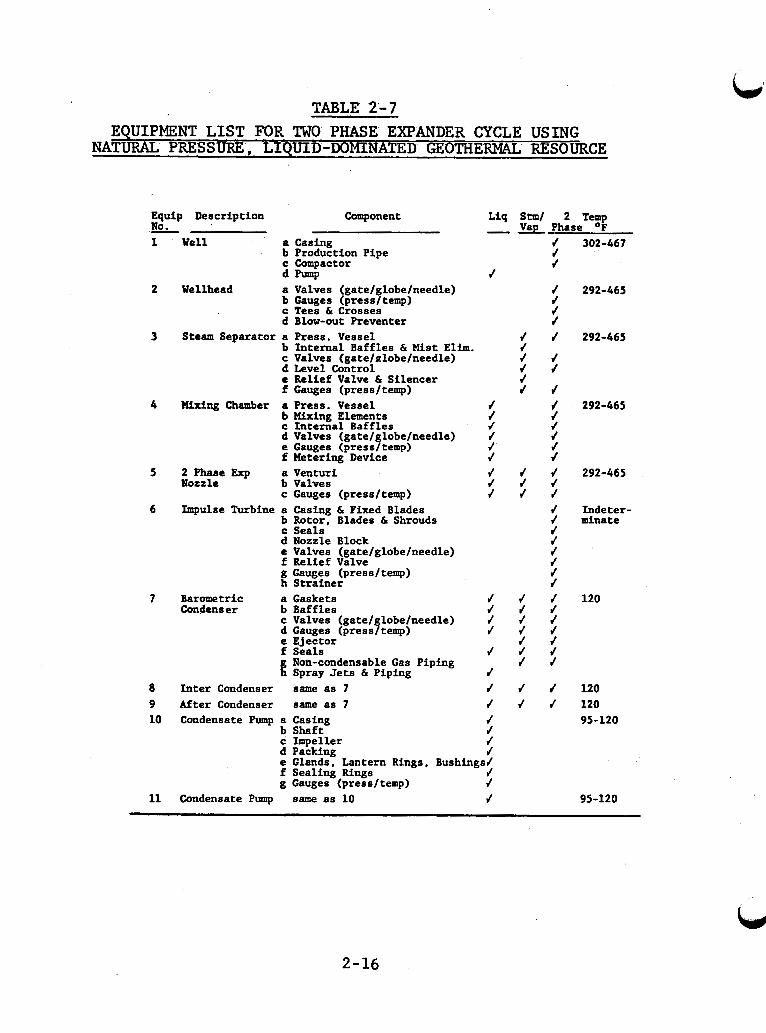
TABLE' 2'-7
2-16
EQUIPMENT LIST FOR TWO PHASE EXPANDER CYCLE USING NATURAL PRESSURE, LIQUID-DOMINATED GEOTHERMAL RESOURCE
Equip Description Component Liq S t m l 2 TT~ - No. - Vap Phase 1 Well a Casing / 302-467
b Production Pipe J c Compactor d d -P J
b Gauges (pressltemp) J c Tees & Crosses J d Blow-out Preventer J
b Internal Baffles & Mist Elim. J c Valves (gatelnlobelneedle) J J d Level Control J J e Relief Valve & Silencer J f Gauges (pressltemp) J f
b Mixing Elements J J c Internal Baffles f / d Valves (gate/ lobelneedle) J 4
f Metering Device J J
c Gauges (pressltemp) J J J
b Rotor, Blades & Shrouds J dnate c Seals J d Nozzle Block J e Valves (gatelglobelneedle) J f Relief Valve J g Gauges (pressltemp) J h Strainer J
Condenser b Baffles d J J c Valves (gate1 lobelneedle) f f J
e Ejector J J f Seals J J J g Non-condensable Gas Piping J J h Spray Jets & Piping
2 Wellhead a Valves (gatelglobelneedle) / 292-465
3 Steam Separator a Press. Vessel d J 292-465
4 Wing Chamber a Press. Vessel J J 292-465
e Gauges (pressftemp) J /
5 2 Phase Exp a Venturi J J J 292-465 Nozzle b Valves J J J
Impulse Turbine a Casing & Fixed Blades J Indeter- 6
7 Barometric a Gaskets J J J 120
d Gauges (press$temp) / / /
J 8 Inter Condenser same as 7 J J J 120 9 After Condenser same as 7 J J J 120 10 Condensate Pump a Casing J 95-120
b Shaft J c Impeller J d Packing J e Glands. Lantern Rings, Bushings/ f Sealing Rings J g Gauges (pressltemp) J
11 Condensate Pump same as 10 J 95-120
.. ~- . , .. . , . . . ., , . -. . .
Figure 2-7. Direct Binary Cycle fo r Pumped, Liquid-Dominated Geothermal Resource
i f
i
i i i i
TABLE 2-8 EQUIPMENT LIST FOR DIRECT BINARY CYCLE USING
PUMPED, LIQUID-DOMINATED GEOTHERMAL RESOURCE !
1 I i i - Vap Phase O F t
J 212-662 t i i i
Equip Description Component Liq Stm/ 2 Temp No. 1 Well a Casing -
t b Production Pipe J c Compactor J d pump
b Gauges (press/temp) J J -J c Tees & Crosses J J J d Blow-out Preventer J J J
Heat Exchanger b Tubes or Coils J c Valves (gate/globe/needle) J J d Relief Valve & Silencer J J e Gauges (press/ temp) J J
P-P b Shaft J c Impeller J d Packing J
f Sealing Rings J g Gauges (press/temp) J
J 2 Wellhead a Valves (gate/globe/needle) J J J 212-662
&
3 Brine/Binary a Press. Vessel J J 212-662
4 Reinjection a Casing J 80-180
e Glands, Lantern Rings, Bushings/
2-18
VENT
GASES NW CaWENSddlE
4
ASSL4WPTloNS I I 1
.- - ~
JAN., I 9 7 8
Figure 2-8. Flashed Steam Binary Cycle for Pumped, Liquid-Dominated Geothermal Resource
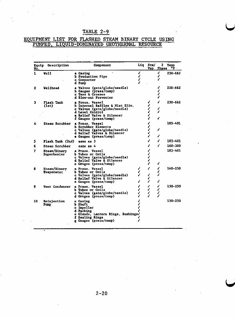
TABLE 2-9. EQUIPMENT LIST FOR FLASHED STEAM BINARY CYCLE USING
PUMPED, LIQUID-DOMINATED GEOTHERMAL RESOURCE
Equip Description Component Liq S t m l 2 Temp No. Vap Phase OF
1
2
3
4
5 6 7
8
9
10
Well (L casing f f 6 Production Pipe f f c Compactor f f d Pump f .
Wellhead a Valves (gatel lobelneedle) b Gauges (press$temp) c Tees h Crosses d Blow-out Preventer
f f d f
Flash Tank a Press. Vessel f f b Internal Baffles h Mist Elb. f c Valves (gate/globe/needle) J f
(1st) d Level Control f f e Relief Valve h Silencer J f Gauges (pressltemp) f f
Steam Scrubber a Press. Vessel b Scrubber Elements c Valves (gatelglobelneedle) d Relief Valves h Silencer e Gauges (pressltemp)
Flash Tank (2nd) same as 3
f f f f 4 J f f f
Steam Scrubber same as 4 J J SteamIBinary a Press. Vessel Superheater b Tubes or Coils
c Valves (gatelglobelneedle) d Relief Valve h Silencer e Gauges (pressltemp)
J J J J f f
SteamIBinary a Press. Vessel f f f Evaporator b Tubes or Coils f f
c Valves (gatelglobelneedle) f J J d Relief Valve h Silencer e Gauges (pressltemp) J f f
Vent Condenser a Press. Vessel J f J b Tubes or Coils / f / c Valves (gatelglobelneedle) 4 J J d Gauges (pressltemp) f J f
Reinjection a Casing f b Shaft f c Xmpeller f
pump d Packing J e Glands, Lantern Rings, Bushings4 f Sealing Rings f g Gauges (pressltemp) J
f
230-662
230-662
230-662
185-401
185-401 160-300 185-401
140-250
130-250
130-250
2-20
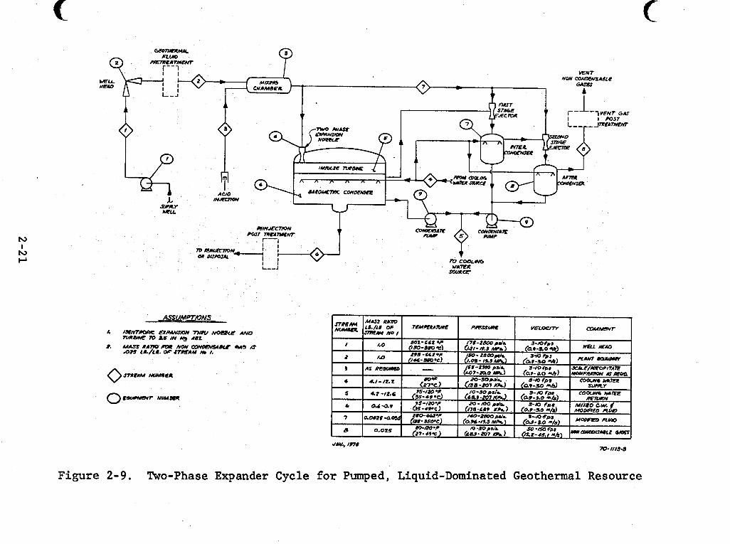
Figure 2-9. Two-Phase Expander Cycle fo r Pumped, Liquid-Dominated Geothermal Resource
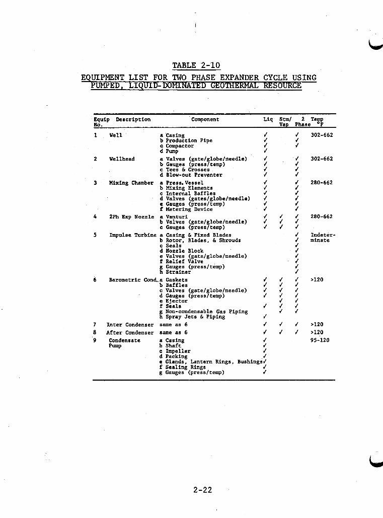
TABLE 2-10 EQUIPMENT LIST FOR TWO PHASE EXPANDER CYCLE U S I N G PUMPED, LIQUID- DOMINATED GEOTHERMAL RESOUR CE
Equip Description Component Liq Stm/ 2 Temp No. Vap Phase OF
J 302-662 1 Well a Casing J b Production Pipe J J c Compactor J J d Pump J
b Gauges (pressltemp) J / c Tees 6 Crosses J J d Blow-out Preventer J J
b Mixing Elements J J c Internal Baffles J f d Valves (gates/globe/needle) f f e Gauges (pressltemp) J 4 f Metering Device f /
b Valves (gate/globe/needle) J J J c Gauges (pressltemp) / J J
b Rotor, Blades. 6 Shrouds f minate c Seals J d Nozzle Block J
2 Wellhead a Valves (gate/globe/needle) J / 302-662
3 Mixing Chamber a Press.Vesse1 J J 280-662
4 2Ph Exp Nozzle a Venturi J / J 280-662
5 Impulse Turbine a Casing IS Fixed Blades J Indeter-
e Valves (gatelglobelneedle) f Relief Valve g Gauges (pressltemp) h Strainer
6 Barometric Cond..a Gaskets b Baffles c Valves (gatelglobeheedle) d Gauges (press1 temp) e Ejector f Seals g Non-condensable Gas Piping h Spray Jets 6 Piping
7 Xnter Condenser same as 6 8 After Condenser same as 6
f J J J
f J J >120 J J J J J f J J J
J J J J J
J J J J J J >120 J J / >120
9 Condensate a Casing J b Shaft J
J c Impeller d Packing J e Glands, Lantern Rings, Bushings/ f Sealing Rings J g Gauges (pressltemp) J
P m P 95-.120
2-22
2.2 Effect of Geothermal Fluid Properties on the Applica- bility of Power Cycles
The applicability of a power cycle to a specific geo- thermal resource depends on characteristics of the fluid. erties that influence the applicability of a power cycle in- clude (1) total dissolved solids and scaling potential, (2) pres- sure and temperature, (3) the liquid to vapor ratio, ( 4 ) chemi- cal comppsition of the fluid, and (5) concentration of nonconden- sable gases. The influence of these properties is discussed in a general way in this section. scribes some potential materials performance problems associated with fluid characteristics for specific process streams in three power cycles.
Prop-
The following Section 2 . 3 de-
Scaling in geothermal systems is a complex phenomenon which is outside the scope of this discussion except as it af- fects corrosion and cycle selection. given resource depend on its temperature and the concentration of relatively minor concentration species: silica, calcium, carbonate, sulfate and heavy metal ions. The tendency for silica scaling increases with decreasing temperature, but pH effects are also important and these depend on both temperature and pro- cessing conditions. ing. position of the individual KGRA fluid.
lized.
Scaling tendencies of a
The pH of most fluids increases on flash- The scaling problem depends heavily on the chemical com-
Scaling affects cycle but requires a numbe of tradeoffs and cannot be genera-
The Rankine Cycle is applicable to steam-dominated sources. Eight cycles are presented for liquid-dominated sources, five for sources recovered by natural pressure and three for sources that require pumping to increase well flow
rate or to keep noncondensable gases dissolved. above, liquid-dominated sources can be treated in flashed steam, binary, or two-phase cycles.
As discussed
Flashed steam cycles are useful for liquid-dominated resources with fluid temperatures above 180°C, but they are ex- tremely sensitive to noncondensable gases. The energy obtained from noncondensable gases in a turbine is small compared to the energy available from steam. So a turbine which handles steam and noncondensable gases must be larger (and more expensive) than one with an equivalent rating which handles steam alone. Noncondensable gases must be continuously removed from condensers and heat exchangers. Flashed steam cycles are applicable for resources with noncondensable gas concentrations less than three weight percent (3 wt. %). Intermediate binary cycles are a use- ful alternative to use of gas ejectors and compressors for re- sources with higher noncondensable gas concentrations.
2.3 Effect of Fluid Properties on Materials Performance In Specific Process Streams
The corrosive nature of geothermal fluids depends mainly on the chemical composition, temperature, and local fluid velocity. determine the corrosiveness of geothermal fluids. describes how the temperature, local velocity, and chemical com- position of the wellhead fluid are altered during the energy extraction process. Defining variations in the corrosive nature of the geothermal fluid in the specific process streams provides a useful framework for selecting construction materials and pre- venting materials problems.
Section 3 describes the key chemical species that This section
The following sections identify potential materials problems in specific process streams in three power cycles for
2-24
natural pressure, liquid-dominated resources. Dual flashed steam, direct binary, and flashed steam binary cycles are con- sidered. tive of those for other cycles. numbers on the flow diagrams in Section 2.2. oxygen in the process streams is assumed unless otherwise stated. As discussed further in Section 5, prevention of oxygen inleakage is a major design goal for any geothermal process.
These cycles were selected because they are representa- The discussions refer to stream
The absence of
2.3.1 Dual Flashed Steam Cycle
Figure 2-3 shows the process streams in a typical dual flash steam cycle.
Stream 1. Wellhead Fluid - This is the highest tem- perature saline stream in the process. The aqueous pH is rela- tively low due to dissolved CO2 and H2S. Corrosivity is deter- mined primarily by the combined effects of temperature, pH, and chloride concentration. Materials problems may be increased by localized flashing leading to high local fluid velocities. can cause erosion/corrosion by entrained solids or impingement. Several observed failures of pipe ells may have been caused by such attacks. Scale deposition from solution may increase loca- lized corrosion problems.
This
Steps must be taken to prevent severe corrosion due to oxygen inleakage during a plant outage. fluid level in a well-during prolonged shutdown can cause air inleakage and considerable damage to well piping.
The sinking of
Stream 2. Fluid from Pretreatment to First Stage Separator - The change in corrosiveness of this stream depends on the pretreatment method. can fncrease the corrosion rate of carbon steel by a factor of
Acidification to reduce scaling
2-25
three or four per unit decrease in pH. generally reduce corrosion of downstream components.
Removal of H P S would
Streams 3 and 10. First Stage Steam to Turbine and Air Ejectors - The high temperature steam will normally contain significant quantities of C O P , some HZS, and lesser amounts of " 3 .
entrained liquid as possible are desirable. This stream should be kept as dry and oxygen-free as possible.
Efficient steam separation and scrubbing to remove as much
Stream 4 . First Stage Flashed Liquid to Second Stage Flash Tank - The liquid stream loses a large fraction of its dissolved C O P and H 2 S on flashing, and the temperature de- creases. Loss of dissolved C O P and H 2 S increases the pH. These effects should offset the increase in chloride concentration due to steam loss , and Stream 4 should be less aggressive than Stream 2.
Stream 5 . Second Flash Steam - This steam should con- tain significantly less C O P than the high temperature steam. Relatively more "3 may be present due to the higher pH of the flashed liquid. The risk of localized condensation is greater for this stream. Entrained liquid removal, dryness, and non- aeration are still important.
Stream 6. Second Stage Flashed Liquid to Disposal - This stream has undergone changes similar to those described under Stream 4 . The absolute changes in C O P , HzS, and pH may be less than for the first flash liquid. The temperature drop is significant, however, and this stream should be less aggres- sive even though chloride concentration is higher. Oxygen in- leakage is an increasing problem since pressure is approaching atmospheric. At this point, the fluid is still hot enough to
2-26
cause stress corrosion cracking of susceptible materials in the presence of small amounts of oxygen.
The post-treatment process (most likely for prevention of injection well plugging) is poorly defined at present. If significant cooling occurs in this process, sulfide stress cracking or hydrogen blistering of downstream components (such as the reinjection well piping) could occur. This form of at- tack fs more prevalent at lower temperatures in aqueous solution and does not necessarily require high concentrations of sulfide.
Stream 7 . Turbine Exhaust to Condensers - This stream will contain little chloride but significant quantities of CO2, H2S, and in some cases "3 from absorption of part of these gases by steam condensate. The aggressiveness of this stream depends on the concentrations of these gases (and their related species) in the liquid and especially on the pH resulting from mixing the "acidic" CO2 and H2S species with "alkaline" "3. The main corrosion problem at Cerro Prieto was in the cooling water system, where condensate was employed in the cooling towers (Appendix A).
Emission of H2S from condensate in cooling towers may be a problem. Addition of ferric salts was used as an emission control method at the Geysers. as an H2S control method, the addition of ferric salts signifi- cantly increa
Although mDderately effective
d sludge disposal problems.
Streams 8 , 11, 12. Condensate and Cooling Water - As noted above , the condensate cooling water streams can pre- sent signif t problems. ling tower aeration can make these problems more acute both by introducing oxygen and by causing the oxidation of sulfide to sulfate which will make the
L)
2-27
Ld stream more acidic. Possible solutions include:
1) increase of-the pH of the circulating stream, 2 ) addition of corrosion inhibitors, and 3 ) use of nonmetallic materials or corrosion re-
sistant alloys.
The use of resistant materials for critical areas (e.g., hydro- gen and oil coolers, instrumentation) is advisable.
2 . 3 . 2 Direct Binary Cycle
Process streams for this cycle are shown in Figure 2 - 4 . The comments for Streams 1 and 2 prior to the heat exchanger are the same as for the dual flash cycle.
Stream 3 in this cycle is saline fluid from the binary heat exchanger. Chemical changes occurring in the saline/binary heat exchanger are more difficult to predict than in the flashed steam case. Since less flashing occurs, the concentrations of COP and H2S will not be decreased as much, and the pH increase due to CO2 and H2S release will be less than in the flashed steam case. Temperature effects on aqueous equilibria and gas solubility will be more important and may tend to make the cooler fluid more acidic.
The precautions given for the cooled, flashed fluid stream generally apply to Stream 3 of the direct binary cycle. The binary cycle Stream 3 may have relatively lower pH and high- er dissolved H2S and CO, concentrations. Combined with lower temperature, these factors could make it more aggressive with regard to sulfide stress cracking or hydrogen blistering. Non- metallic materials may be useful for some applications in this environment. L E J
2-28
,
'L/
,
,
n
1
W
Conventional materials will most likely be used for the binary fluid equipment. exchanger must be resistant to pitting and crevice corrosion to prevent leakage of hot saline fluid to the binary loop. Resis- tance of the material to solutions used for scale removal must also be considered.
The thin-walled parts of the heat
At some sites it may be necessary to use part of Stream 3 for cooling water. Usefulness will depend on control of the scaling tendencies of the fluid after concentration and possibly on cooling tower H2S emissions. lower in H2S and'C02 than the flashed steam condensate, this stream is more saline. more aggressive due to the added dissolved oxygen and the lower pH from sulfide oxidation. sate Steams 8, 11, 12 in the dual flashed steam cycle are recom- mended.
Although probably
Cooling tower aeration will make it
Control methods given for conden-
2.3.3 Flashed Steam Binary Cycle
The effects of processing on the geothermal fluid are the same as for the dual flashed steam cycle.
The main distinction from a corrosion standpoint is that steam is used in the binary heat exchangers instead of saline liquid.
The use of steam circumvents scaling problems but does not prevent corrosion problems. C02 has been found to be innocuous at Wairakei and Cerro Prieto when "dry," but high corrosion rates for several materials have been found at Salton Sea. Steam condensate can be a corrosive liquid depending on the concentrations of dissolved H2S, CO2,
Steam containing H,S and
2-29
and NH3 and the resu l t tng pH. Eff ic ien t steam separation and scrubbing are important t o minimize chloride carry-over from the l iqu id .
The discussion of flashed geothermal l i qu id f o r cool- ing w a t e r i n Section 2 .3 .1 a l so appl ies t o flashed steam binary cycles.
2-30
3.0 CHEMICAL COMPOSITION OF GEOTHERMAL FLUIDS FROM A CORROSION STANDPOINT
Results of materials performance tests are analyzed based on the chemical composition of the corrosive medium and physical fac tors such as temperature, duration of exposure, and f l u i d ve loc i ty . t o use tes t r e s u l t s t o pred ic t materials performance i n other systems. character izat ion i s d i f f i c u l t but e s s e n t i a l . t i f i e s chemical components i n geothermal f lu ids t h a t a r e s ign i - f i can t i n determining cor ros iv i ty . ical composition data f o r predict ing f l u i d cor ros iv i ty i s con- sidered. U . S . geothermal resources i s presented.
These var iables must be w e l l defined i n order
Geothermal f l u i d s are complex, var iab le mixtures whose This sect ion iden-
The u t i l i t y of ex is t ing chem-
A summary of chemical composition of f l u i d s from seven
3.1 Key Corrosive Chemical Species
Geothermal f lu ids contain s i x key chemical species t h a t
These key species w e r e i den t i f i ed from an analysis produce a s ign i f i can t corrosive e f f e c t on meta l l ic construction materials. of corrosion l i t e r a t u r e and an examination of the data on chem- i c a l composition of f l u i d s from liquid-dominated geothermal re- sources. and therefore t h e ones t h a t should be analyzed i n a l l geothermal environments.
They are the most common and aggressive corrosive species
Geothermal f l u i d s are complex chemical solut ions con- ta in ing many d i f f e ren t species. and t h e i r important gas and l i q u i d phase chemical forms are l i s t e d below:
The s i x most s ign i f i can t species
Hydrogen ion
3-1
I
Chloride ion
Hydrogen su l f ide
Carbon dioxide, Carbonate and Bicarbonate ion
Sul fa te ion
The iden t i f i ca t ion of these species as the most s ign i - f i can t i s complicated by t h e following fac tors :
Materials respond t o a given chemical species i n d i f f e ren t ways and degrees.
The importance of a given species o f t en depends on i ts concentration relative t o other species .
The in te rac t ion of two o r more chemical species may give r e s u l t s d i f f e ren t from those obtained with the individual species .
The temperature dependence of corrosion by a given species i s of ten undefined.
The importance of a given species depends on the form of a t tack (uniform, local ized, cracking).
Other chemical species t h a t are less common o r aggressive can a l so produce corrosive e f f e c t s i n some geothermal f l u i d s . p les are f luor ide ion, heavy metals, and boron. no t normally a component of high-temperature geothermal f l u i d s , g rea t ly increases t h e i r corrosive effects. The accidental
Exam- Oxygen, while
3-2
introduction of oxygen t o a geothermal process stream has pro- duced very ser ious corrosion problems i n ex is t ing geothermal e l e c t r i c power p lan ts .
Scaling o r s o l i d s deposition i s another aspect of geo- thermal f l u i d chemistry t h a t influences materials performance. Prec ip i ta t ion of l i q u i d phase species i n so lu t ion o r on equip- ment surfaces can influence corrosion rates and cause erosion. The composition of t h e scale-forming so l ids and the rate of pre- c i p i t a t i o n depend on f l u i d composition and spec i f i c process stream conditions, so scale-forming species are not included i n the l i s t of key species.
Some generalizations about the corrosive effects of the key species , oxygen, and t r ans i t i on metal ions on construc- t i o n materials are given i n the following paragraphs. This sub- ject i s t r ea t ed i n more depth i n Section 5 .0 , which provides de- t a i l s about the forms of a t t ack fo r spec i f i c metals and a l loys .
Hydrogen ion (pH) - The general corrosion rate of carbon steels increases rap id ly with decreasing pH, espec ia l ly below pH 7. Breakdown of pas- s i v i t y a t l o c a l areas can lead t o ser ious forms of a t t ack , e .g . , p i t t i n g , crevice corrosion, and stress corrosion cracking.
Pass iv i ty of many a l loys i s pH dependent.
Chloride - Chloride causes l o c a l breakdown of passive f i l m s which pro tec t many metals from uniform a t tack . Local pene- t r a t i o n of t h i s f i l m can cause p i t t i n g , crevice corrosion, o r stress corrosion cracking. Uniform corrosion rates can a l so increase with increasing chloride concentration, but t h i s ac t ion is generally less ser ious than l o c a l forms of a t t ack .
Hydrogen Sulf ide - Probably the most severe e f f e c t of H2S i s i t s a t t ack on ce r t a in copper and n icke l a l loys . metals have performed w e l l i n seawater but are p r a c t i c a l l y
These
3-3
unuseable i n geothermal f lu ids containing H 2 S . on iron-based materials i s less predictable . occurs i n some cases and inh ib i t ion i n o thers . steels are of ten subject t o su l f ide stress cracking. a l so cause hydrogen b l i s t e r i n g of steels. aerated geothermal process streams increases the ac id i ty of the stream.
The e f f e c t of H 2 S Accelerated a t t ack
High-strength H 2 S may
Oxidation of H2S i n
Carbon Dioxide - In the ac id ic region, C02 can accel- e r a t e t he uniform corrosion of carbon s t e e l s . thermal f lu ids and process streams i s l a r g e l y control led by C O 2 . Carbonates and bicarbonates can display mild inh ib i t i ve e f f e c t s .
The pH of geo-
Ammonia - Ammonia can cause stress corrosion cracking It may a l so accelerate the uniform corrosion of copper a l loys .
of mild steels.
Sul fa te - Sulfa te plays a minor r o l e i n most geothermal f l u i d s . aggressive anion. severe local ized a t t ack as chlor ide.
In some low chloride streams, s u l f a t e w i l l be the main Even i n t h i s case, i t r a re ly causes the s a m e
Oxygen - The addition of s m a l l quan t i t i e s of oxygen t o a high-temperature geothermal system can greatly. increase the chance of severe local ized corrosion of normally r e s i s t a n t metals. The corrosion of carbon steels i s sens i t i ve t o t race amounts of oxygen.
Transit ion Metal Ions - "Heavy" o r t r ans i t i on m e t a l ions might a l so be included as key species. concentrations on most construction materials i s i l l -de f ined . However, the poor performance of aluminum a l loys i n geothermal f lu ids may be due i n p a r t t o low l eve ls of copper o r mercury i n these f l u i d s .
Their ac t ion a t low
Salton Sea geothermal f lu ids contain many t r a n s i t i o n
3- 4
metal ions a t greater than "trace" concentrations. forms of t r a n s i t i o n metal ions (Fe+3, CU'~, e t c . ) are corrosive, but these ions are present i n the lowest oxidation s ta te (most reduced form) i n geothermal f l u i d s . t o Fe+3 which i s another reason to exclude oxygen from geothermal streams.
3 . 2 Key Corrosive Chemical Species i n Selected KGRA's
Some oxidized
Oxygen can convert Fe+2
The concentrations of key species i n geothermal f lu ids must be defined i n order t o use the r e s u l t s of materials perfor- mance t e s t s . completely defined, then the r e s u l t s can be used t o pred ic t ma- terials performance i n other systems. s ider the a p p l i c a b i l i t y of ex i s t ing composition data . Analyses of springs or other r e l a t e d surface sources are of no use f o r predicting corrosion i n geothermal power cycles. Although a la rge number of geothermal w e l l analyses have been completed (LA-312), much of these dat
If corrosion tes t conditions a re accurately and
So i t i s useful t o con-
re of l imited u t i l i t y f o r predict- ing materials performance. The u t i l i t y of the data may be l imited f o r the following reasons :
One o r more of t h (H2S and N H 3 are the most common omissions).
key species were not analyzed
Other important c to r s such as temperature, w e l l flow rate , o r flow Cime were not speci- f i e d .
I
The accuracy the ana ly t ica l r e s u l t s w a s not indicated. and the method of sample acquis i t ion and analy- ses were not described. tat ive sample of downhole f l u i d presents a number of experimental d i f f i c u l t i e s (NE-302).
Error l i m i t s were not spec i f ied ,
Obtaining a represen-
3-5
Chemical analyses w e r e done on flashed f l u i d , and the conditions under which f lashing occurred w e r e e i t h e r uncontrolled o r unspecified.
Flashing causes changes i n the pH and the concentrations of H Z S , C 0 2 and NH3 i n the f l u i d . I f these components are mea- sured i n the flashed f l u i d , the r e s u l t s are not representat ive of concentrations i n the unflashed f l u i d . The usefulness of flashed f l u i d data i s l imited i f they cannot be used t o ca lcu la te concentrations i n the unflashed streams. The f lash ing conditions must be specif ied and t h e flashed steam must be analyzed f o r H2S, CO2 and " 3 . Such data are scarce and hard t o obtain because of d i f f i c u l t i e s i n the sampling procedures.
A p a r t i a l l i s t of information required with any reported analysis i s given below.
w e l l shut-in periods, recent reservoir engineering, t o t a l s t a b i l i z a t i o n time, f l u i d flow rate from w e l l , i den t i f i ca t ion of two-phase flow, and spec i f i c sampling procedures and conditions
T y p i c a l concentrations of key corrosive chemical species i n f l u i d s from seven "known geothermal resource areas" (KGRA's) are shown i n Tables 3-1 and 3-2. These data are the r e s u l t of a review and ana lys i s of a l l avai lable chemical composition data f o r U.S. and foreign geothermal resources. The review showed t h a t data character iz ing key species a re ava i lab le f o r seven U.S. KGRA's and two foreign resources (Cerro P r i e to , Mexico and Wairakei, New Zealand, see Appendix A). KGRA's f o r which reason- ably complete character izat ions of key species are ava i lab le include Salton Sea, East Mesa, Heber, Mono-Long Valley, Baca (Valles Caldera), Beowawe, and 'Raft River.
3-6
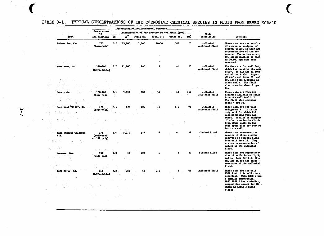
TABLE 3-1. TYPICAL CONCENTRATIONS OF KEY CORROSIVE CHEMICAL S P E C I E S I N F L U I D FROM SEVEN KGRA'S Properties of the Geothe-1 Resource
Fluid T ' a p r r B h l I e
*C Wncrntration of Key Species i n the ?h id (ppd K G U and location pa Cl - Total UJ, Total RtS Total l l s r 60; Description Caent.
saltno sea. c..
met m, c..
h f t River. Id.
250 5.2 (bore-hole)
1MI-200 5.7 (bora-hole)
1-200 7.1 (bore-hole)
175 6.5 (bore-hole)
171 6.8 (well-head
at 110 pBig)
132 9.3 (mll-bud)
U b 7.2 bore-hole)
115.000
11.wo
9.000
227
3.770
50
780
L.000
800
180
180
128
209
60
10-30 300
3
%2
14
6
6
0.1
41
13
0.1
-
3
2
20
20
152
96
59
89
61
unfluhed well-head fluid
unf lashed well-head fluid
unflaahed well-head fluid
unf lashed well-head fluid
fluhed fluid
flashed fluid
d l a s h e d fluid
Them data are the reaulta
several wells. BO they are repreaentati*. of the re- source. Variation. occur; UJr concentratiom u high u 10.000 p p haw been
Thm data are for ve l l 6-1.
Of eXtmBiVB aM1YB.s Of
measured.
which he. rsceived the m0.t study. It M y M t be tlpi- eel of the field. UQher pH (6.5) and lover C 1 and COX h e w been meuured at other wells. TIIB fluid also contains .bout 9 ppm ?e.
These data are from two separate analpea of fluid from the well m l i n 1. The fluid elao c a n t a h about 4 ppm Fe.
Theae data are for w e l l Endogenous 4. It is the only well for which ltsS eoncentratloas were mea- sured. &8UlCB Of -8lyBeS Of other BpeCieB i n flUfdB from other d m in the area agree with the ruults
These data represent the re8ultr of three .hilar analyses of f luhed fluid from w e l l B ~ C B 11. They are not repressntativa of values in t h e unflmhed fluid. These data are repreaentr
and 4 . Dats for BrS. Wz. W, and pB are not repre- sentative of the unfluhad fluid. These data are for vell #XtX 1 which is W11 eb.r ecteriaed. Well RRCE 2 bu e s w l a r colpoaition. Ikll #XtX 3 h u a .hilar- emposition except for C l . higher.
for this Wll .
ti- Of wells V d U D 2. 3.
Vhieh b .bout 3 t b C B
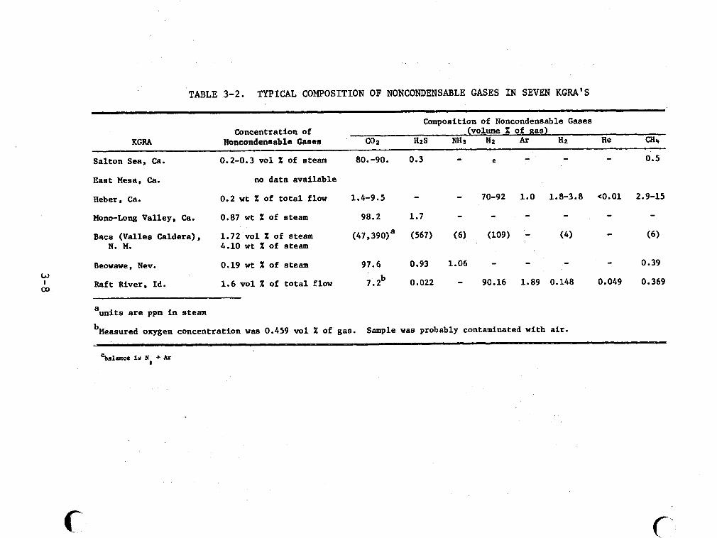
w I co
TABLE 3-2. TYPICAL COMPOSITION OF NONCONDENSABLE GASES IN SEVEN KGRA'S ~
Composition of Noncondensable Gases (volume X of gas) Concentration of
KGRA Noncondenaable Gases co 2 H 2 S "3 N B At H B He a 4
Salton Sea, Ca. 0.2-0.3 vol X of steam
East Mesa, Ca. no data available
Heber, Ca.
Mono-Long Valley, Ca.
Baca (Valles Caldera), 1.72 vol X of steam
0.2 wt X of total flow
0.87 wt X of eteam
N. M. 4.10 wt X of steam
0.19 wt X of steam Beowawe, Nev.
Raft River, Id. 1.6 vol X of total flow
a units are ppm in steam
80.-90.
1.4-9.5
98.2
(47 ,390)a
97.6
7.2 b
0.3
- 1.7
(567)
0.93
0.022
C
70-92
- (109)
- 90.16
1.0 1.8-3.8 e0.01 2.9-15
- - - - - (4) - (6)
- - - 0.39
1.89 0.148 0.049 0.369
bMeasured oxygen concentration was 0.459 vol X of gas. Sample was probably contaminated with air.
Cbalmce is N + Ar
C'
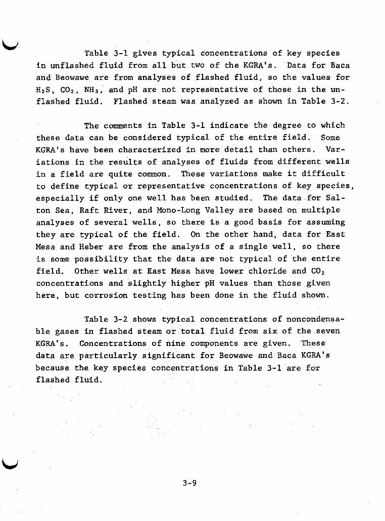
Table 3-1 gives typical concentrations of key species i n unflashed f l u i d from a l l but two of the KGRA's. Data fo r Baca and Beowawe are from analyses of flashed f l u i d , so the values fo r H 2 S , C O 2 , N H 3 , and pH are not representat ive of those i n the un- flashed f l u i d . Flashed steam w a s analyzed as shown i n Table 3-2.
The comments i n Table 3-1 ind ica te the degree to which these data can be considered typical of the e n t i r e f i e l d . KGRA's have been characterized i n more d e t a i l than o thers . V a r - i a t i o n s i n the r e s u l t s of analyses of f lu ids from d i f f e ren t w e l l s i n a f i e l d are qu i t e common. These var ia t ions make i t d i f f i c u l t t o define typ ica l o r representat ive concentrations of key species , espec ia l ly i f only one w e l l has been s tudied. ton Sea, Raft River, and Mono-Long Valley a r e based on multiple analyses of several wel l s , so there i s a good bas is f o r assuming they are typ ica l of the f i e l d . On the other hand, da ta fo r E a s t Mesa and Heber are from the analysis of a s ing le wel l , so there i s some p o s s i b i l i t y t h a t the data are not typical of the e n t i r e f i e l d . Other w e l l s a t East Mesa have lower chloride and C02 concentrations and s l i g h t l y higher pH values than those given here, bu t corrosion t e s t i n g has been done i n the f l u i d shown.
Some
The data fo r Sa l -
Table 3-2 shows typica l concentrations of noncondensa- b l e gases i n flashed steam o r t o t a l f l u i d from s i x of t he seven KGRA's. Concentrations of nine components are given. These data are pa r t i cu la r ly s ign i f i can t f o r Beowawe and Baca KGRA's because the key species concentrations i n Table 3-1 are f o r f lashed f h i d .
3-9
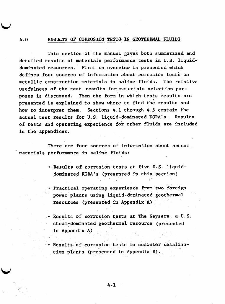
4.0 RESULTS OF CORROSION TESTS IN GEOTHERMAL FLUIDS
This sect ion of the manual gives both summarized and de ta i led r e s u l t s of mater ia ls performance tests i n U.S. l iquid- dominated resources. F i r s t an overview i s presented which defines four sources of information about corrosion tests on meta l l ic construction mater ia ls i n s a l ine f lu ids . The r e l a t i v e usefulness of t he t e s t r e s u l t s f o r mater ia ls se lec t ion pur- poses i s discussed. Then the form i n which t e s t s r e s u l t s are presented i s explained t o show where t o f ind the r e s u l t s and how t o in t e rp re t them. Sections 4.1 through 4.5 contain the ac tua l test r e s u l t s for U. S. liquid-dominated KGRA's. Results of tests and operating experience f o r other f lu ids are included i n the appendices.
There are four sources of information about ac tua l mater ia ls performance i n sa l ine f lu ids :
Results of corrQsion tests a t f ive U.S. l iquid- dominated KGRA's (presented i n t h i s sect ion)
Prac t ica l operating experience from two foreign power plants using liquid-dominated geothermal resources (presented i n Appendix A)
Results of corrosion tests a t The Geysers, a U.S. steam- dominated geothermal resource (presented i n Appendix A)
Results of corrosion tests i n seawater desalina- t i o n p lan ts (presented i n Appendix 3 ) .
4-1
Previous experience i s of the utmost importance i n corrosion engineering. Development of U. S. liquid-dominated geothermal resources i s i n the ea r ly s tages , but power p l a n t s using t h i s type of resource are already operational a t Wairakei, New Zealand and Cerro Pr ie to , Mexico. Appendix A contains a summary of corrosion data from these two s i t e s . Cerro Pr ie to are pa r t i cu la r ly important because the plant i s located on the California-Mexico border. propert ies a t Cerro P r i e to are similar t o those i n some Cal i fornia resource areas.
The data from
The geothermal f l u i d
The United States has an operating power plant a t t he Operating experience from Geysers, a steam-dominated resource.
the Geysers plant i s of i n t e r e s t because it provides data on corrosion i n steam and condensate. But these streams have lower chloride concentrations than equivalent streams from l iqu id- dominated resources.
Many materials have been t e s t e d i n seawater desalina- t i on p lan ts a t temperatures up t o 120°C. cate some materials su i t ab le f o r lower temperature process streams i n geothermal power cycles. ments on app l i cab i l i t y t o geothermal systems are given i n Appendix B.
T e s t r e s u l t s may ind i -
General f indings and com-
4.1 Corrosion Tests a t U. S. Liquid-Dominated KGRA' s
Emphasis i n t h i s sect ion i s placed on recent corrosion tests a t U . S . liquid-dQminated KGRA's . Some generalizations are made about materials performance i n f lu ids from seven KGRA's. T e s t r e s u l t s fo r f i v e of the KGRA's a r e presented i n separate sect ions.
4-2
Wellhead f lu ids from seven liquid-dominated KGRA's have been c l a s s i f i e d i n three broad categories: moderately corrosive, and least corrosive. The information avai lable about corrosion i n these f lu ids i s s t i l l too l imited t o allow accurate pred ic t io about the performance of s p e c i f i c materials. vide a framework f o r comparing r e s u l t s f o r d i f fe ren t resources.
4.1.1 Most Corrosive: Salton Sea
most corrosive,
The broad categories are useful because they pro-
High uniform corrosion r a t e s and loca l ize p la in carbon steels by Salton Sea f lu ids have been observed. Many commonly used al loys are subject t o local ized a t tack i n these f lu ids . ent marginal usefulness of carbon steel i s of concern.
Resistant materials are avai lable , but the appar-
The chloride concentration of most Salton Sea f lu ids i s about ten t i m e s higher than tha t of the next highest KGRA. COP and HzS concentrations compared t o Cerro P r i e to and Wairakei f l u ids . The ammonia con-
re f a i r l y high but not exceptional
centrat ion does appear t o be high compared t o these sources and other KGRA's. low, but ac'idification t o pH ing. corrosive components i n t h i s f l u i d .
The pH (5.2) o f thds resource is relatively . 5 may be needed t o control sca l -
The s u l f a t e concentration i s negl ig ib le compared t o other
4.1. Long Valley, Raft River
The compositions and l imited corrosion r e s u l t s f o r esources ind ica te t h a t behavior should be similar. ompositions are b those a t Wairakei and Cerro
Pr ie to f o r which long-te However, s imple power cycles are used a t these p lan ts and mate- r ia ls se lec t ion may be c r i t i c a l f o r more complex cycles.
e r a t ing experience i s avai lable .
4-3
Lid The most extensive data are available for Raft River.
Limited data are available for East Mesa (well 6-1), Baca, and Heber. Corrosion data are not available for Mono-Long Valley. A brief overview of results and reasons for the moderately corrosive classification is given below.
Available results indicate that the uniform corrosion rate of plain carbon steels should be about 2-10 mpy in'these fluids. River and crevice corrosion at East Mesa. These forms of corro- sion will probably limit the use of carbon steels to relatively thick-walled equipment.
Pitting and crevice corrosion were observed at Qft
Material selection for thin-walled and critical compo- nents will be more difficult. Test results at Raft River are instructive since extensive localized corrosion of many "resis- tant" alloys was observed even in this relatively low chloride (~780 ppm) and near neutral (pH 7.2) fluid. Shorter duration tests at East Mesa and Heber show similar results. Preliminary indications are that attack is no worse at these sites than at Raft River. to localized attack. Section 4 . 5 .
Alloys such as Type 316 and 26Cr-1Mo are subject More detailed information in presented in
The low H2S content of Raft River fluids is probably
Performance of unusual, and the copper-based alloys found to be acceptable may be subject to H2S attack in most other fluids. copper-nickel alloys was poor even in Raft River fluid.
As noted in Section 3 , Table 3-1, most new wells at East Mesa have significantly lower chloride concentrations and somewhat higher pH values than well 6-1 where most corrosion testing has been done.
4-4
4 , l . 3
Corrosion data i n Baca wellhead f l u i d are limited. Corrosion i n the flashed steam from t h i s source has received more a t ten t ion . Baca indica tes po ten t i a l corrosion problems. If the pH of unflashed f l u i d is much lower, w e l l piping could be subject t o ser ious at tack. The H2S content of unflashed f l u i d i s of s i m i - l a r concern.
The r e l a t i v e l y low pH of the flashed f l u i d a t
Mono-Long Valley i s t en ta t ive ly included i n t h i s c lass even though it has a low chloride concentration. The pH of t h i s f l u i d i s lower, and wellhead temperature i s higher than R a f t River. Combined with r e l a t i v e l y high H 2 S levels, these fac tors make it po ten t i a l ly as corrosive as o ther members of t h i s class.
Least Corrosive : Beowawe
The chloride concentration of Beowawe f lu ids i s low and pH of t he flashed f l u i d i s high (pH $9.3). These fac tors should make t h i s f l u i d less corrosive t o iron-based a l loys than those i n the moderately corrosive category. However, the H2S content of t h i s f l u i d w i l l make it aggressive toward ce r t a in copper-based and nickel-copper a l loys. Sulfide stress cracking and hydrogen b l i s t e r i n g of ce r t a in steels are a l so possible. The chloride content i a hxgh enough t o cause stress corrosion cracking and local ized a t tack of suscept ible a l loys , espec ia l ly i n the presence of oxygen.
Tables 4-1 and 4-2 show the ferrous and nonferrous materials t h a t have been t e s t ed a t e ight geothermal resources including Cerro P r i e to , Wairakei, the Geysers, and f ive l iquid- dominated U.S. KGRA's. Table 4-3 describes the nominal composi- t ions of brand name a l loys t h a t have been tes ted .
4-5
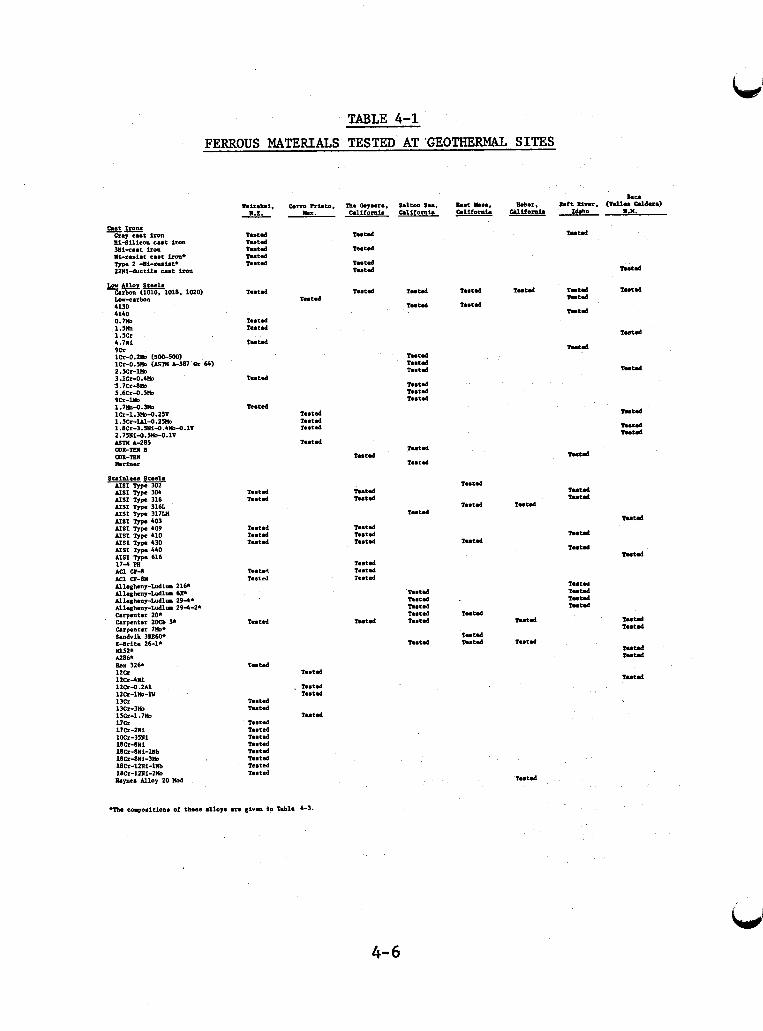
ui-rniat C..t h. Type 2 -I(i-*..i.t* 22Ni-ductile cast iron
im-3m lscr-1.7m 17Cr 17h-211i 10Cr-3SNi 18R-8Ui 10Cr-8Ai-m 18RdNl-3m 18Cr-12Ni-lllb 18m-lzwi-zm
TABLE 4-1 FERROUS MATERIALS TESTED AT GEOTHERMAL SITES
Nair.L.i, U.Z.
Tested h.td h'td T U t d h.td
h.td
T W t d ?e. td
h.td
h'td
h.td
h.td h.td
1e.t.d 1ee.t.d h.td
*.td h.te.3
h.td
1e.t.d
h'td I*.td
T.St.6 mmtd h.td Testd T...td 1e.t.d Tested Tested
htd h.td 1"td
?...tad
T U t d
T"td T W t d
h.td
h.td
htd h O t d
Tutd
T U t d h.td T u r d
T * * t d I..td h.td
6dtm Ilu. California
T U t d
htd
Testd T U t d I..td
T u r d h.td h.td
Iutd
T..td
1"td
h.td
Tutd T..td T U t d
mtd
T U t d
T U t d
T U t d
T U t d
htd
htd
h.td
htd h.td
Ember. mifomia
z u t d
T..td
htd
Tutd
htd
htd htd
htd
htd
hud
htd Iutd
htd
Mud
? u t a T U t d Tutd h'td
Tutd
Iutd
htd
Tuud
h.td
htd
h u d T w t d
htd n n t d
htd
. . . ... . . Upe. N l o y 20 Mod
4= 6
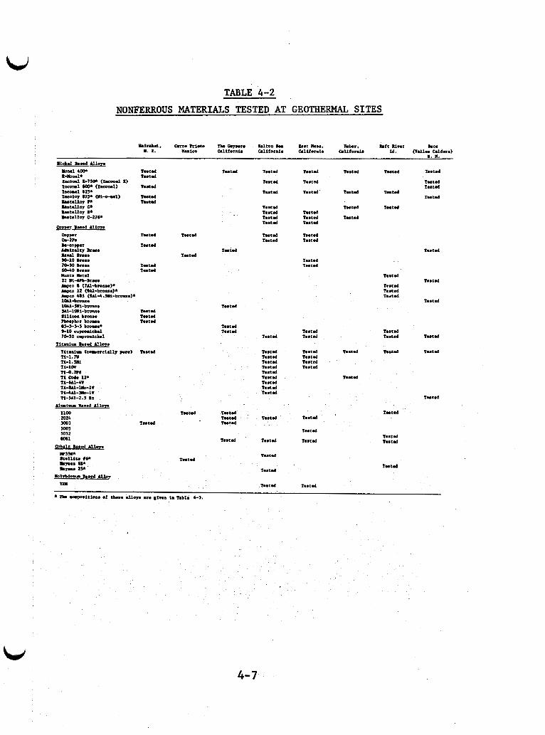
TABLE 4-2 NONFERROUS MATERIALS TESTED AT GEOTHERMAL SITES
1nt.d
1"t.d
1"td 1nt.d
1"t.d h.td T n t d 1nt.d
1eet.d
1nt.d I...t.d
T..tSd
T..t.d 1nt.d
1"t.d
1nt.d 1nt.d
T..t.d
T n t d
1nt.d
4- 7
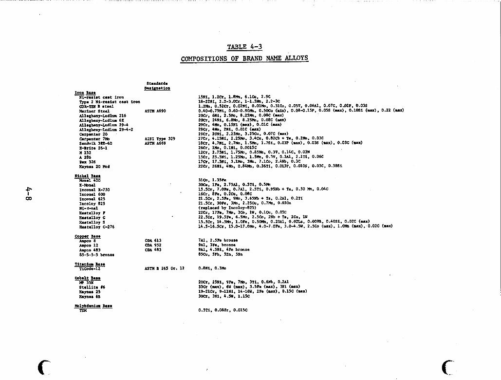
TABLE 4-3
COMPOSITIONS OF BRAND NAME ALLOYS
Standards ~ . s i w s t i ~ t ~
Iron Bsma -- Ni-resist cas t iron Type 2 Ni-resist cas t iron COB-Tw B steel Mariner S tee l ASTM A690 Nlegheny-Ludlm 216 Nlegheny-ludlru 6X Nleshay-Ludlm 29-4 Nleghmy-Ludlm 29-4-2 Carpenter 20 Carpnter 7 0 A I S 1 Type 329 S.ndvik 3BE-60 ASTM A669 E-Brit. 26-1 U 152 A 286 Rex 326 Haynss 20 Hod
15Ni. 1.2h. 1.8%. 6.1CU. 2.9C 18-22111. 2.2-3.oh. 1-1.5M1~ 2.2-3C 1.2M 0.4&.75Ni, 0.60-0.90%. 0 . 5 0 ~ ~ (.in), 0.08-O.15P. 0.0% (mu) , 0.1OSi (mx) , 0.22 (mu) 20h. 6Ni. 2.50. 8.25M. 0.08C (UX) 20Cr, 24Ni. 6.00. 8.25%. 0.08C (mu) 29Cr. bn0, O.15NI ( M X ) . 0.01c (nU) 29Cr. 4%. 2Ni. 0.01C (ux) 29Cr. 20N1, 2.250, 3.250~. 0.07C ( M X ) 27Cr 4.15111, 2.25n0. 3.4Cu. 0.82Cb + Ta, 0.2M. 0.03C 18Cr: 4.7111, 2.7wO. 1.5M. 1.7St.. 0.03P (mx). 0.03s ( u x ) . 0.03C (maX) 26h . Wo. O J N I . 0.0015C 12Cr. 2.75111, 1.750. 0.851h. 0.3V. 0.14C. 0.03N 15Cr. 25.511, 1.251b. 1.5%. 0.1V. 0.3N. 2.1Ti . 0.06C 17Cr. 17.5111, 3.Wo. 3%. 7.1c4. 2.4Nb. 0.3C 22Cr. 26Ni. 4n0. 0.84%. 0.36T1, 0.013P. 0.01OS. 0.03C. 0.5851
0.52Cr. O.O2Ni, 0.010, 0.31Cu. 0.050. 0.06N. 0.07C. OJ)lP, 0.03s
IC-0nal Inconel X-750 Inconel 600 Inconel 625 Incoloy 825 Ni-0-ne1 nastelloy F 8.stalloy c Hastellop S Hostelloy C-276
Comer Esse Ampco 8 h p c o 12 Ampco 483 85-5-5-5 bronze
Titanium Esse -- TiCoda-12
Oobalt Bas. MP 3511 S t a l l i t a 16 Hamas 25 Habas 6B
Wlybdanim br.. TW
CM 613 CDA 952 CDA 483
31131. 1.35Fe JOCu, lFe, 2.75Al. 0.5Ti. 0.51h 15.5Cr. 7.0Fe. 0.7Al. 2.5Ti. 0.95Nb + Ta. 0.50 %, 0.04C 16Cr. 8Fe. 0.2CU. 0.08C 21.5Cr. 2.5Fe. 9Uo, 3.65Nb + To, 0.2A1. O.2Ti 21.5Cr. 30Fe. 3Ih. 2.25Cu. 0.7h. 0.03Cu (replaced by Incoloy-825) 22Cr. 17Fe. 7%. 3Co. l W , O. lCU, 0.05C 22.5Cr. 19.5Fe. 6.50. 2.5120. 2Nb + Ta, 2Cu. 1 W 153%. 14.50. l.OFe, 0.50M. 0.2W1, 0.02L.a. 0,0091). 0.40Si. 0.02C t u x ) 14.5-16.5Cr. 15.0-17.00, 4.0-7.0Fe. 3.0-4.5U. 2.5Co (max). 1.0% (sax). 0.02C (mx)
7N. 2.5Fe bronze 9N. 3Fe, bronze 9N. 4.511, 4Pe bronze 85CU. 5Pb. 5Zn. 5Sn
WTH B 265 Cr. 12 0.811, 0 . 3 0
20Cr, 25N1, 9Fe. 7n0, 3Ti. 0.6Nb. 0.2N 33Cr (ma.). 6W ( u x ) . 3 . 5 h ( u x ) . 311 ( u x ) 19-2lCr. 9-11Ni. 14-16W. 2Fe (ux), 0.15C ( u x ) 30Cr. 3 l i . 4 . N . 1.1%
0.5Ti. 0.08Zr. 0.015C
c f
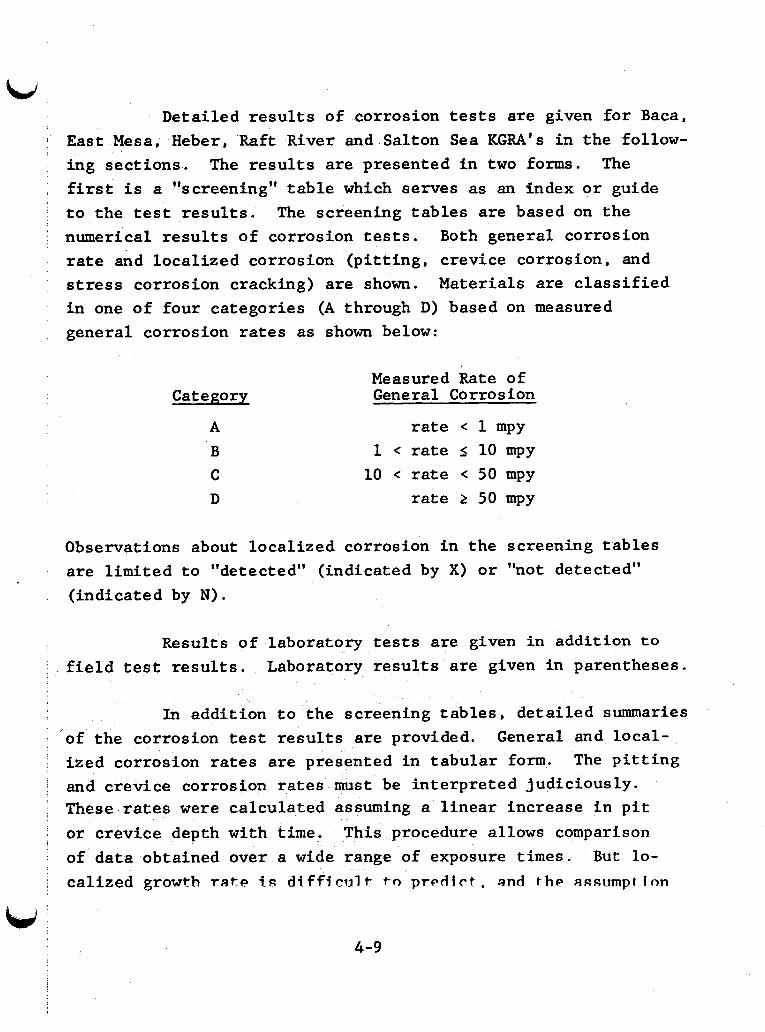
Detailed r e s u l t s of corrosion t e s t s are given f o r Baca, East Mesa, Heber, Raft River and Salton Sea KGRA's i n the follow- ing sect ions. The r e s u l t s are presented i n t w o forms. The first i s a to the test r e s u l t s . The screening tab les are based on the numerical r e s u l t s of corrosion t e s t s . Both general corrosion r a t e and local ized corrosion (p i t t i ng , crevice corrosion, and s t r e s s corrosion cracking) a re shown. Materials are c l a s s i f i ed i n one of four categories (A through D) based on measured general corrosion r a t e s as shown below:
( 1 screening'' t ab l e which serves as an index o r guide
Category
A B C D
Measured Rate of General Corrosion
r a t e 1 mpy 1 r a t e I 10 mpy
10 c r a t e < 50 mpy r a t e 2 50 mpy
Observations about local ized corrosion i n the screening tab les are l imited t o "detected" (indicated by X) o r "not detected" (indicated by N).
Results of laboratory t e s t s are given i n a d d i t i o n t o f i e l d t e s t r e s u l t s . Laboratory r e s u l t s are given in parentheses.
In addition t o the screening t a b l e s , de ta i led summaries of the corrosion t e s t r e s u l t s a re provided. General and local- ized corrosion r a t e s are presented in tabular form. The p i t t i n g and crevice corrosion r a t e s must be interpreted judiciously. These r a t e s were calculated assuming a l i nea r increase i n p i t or crevice depth with time. This procedure allows comparison of data obtained over a wide range of exposure times. But lo- cal ized growth rate t s d i f f i c u l t t o predict, and t h e assumption
4-9
of a linear growth rate is not always accurate. In actuality, a given pit may stop growing, grow at a slower rate for longer times, or accelerate in growth. An induction time before pit initiation is often observed which further complicates data in- terpretation.
I
4- 10
4.2 Results of Corrosion Tests at Baca (Valles Caldera) New Mexico KGRA
Corrosion data for Baca flashed fluids and steam are summarized in Tables 4-4 and 4-5. The limited number of test results was obtained in flashed wellhead fluid and steam; results are unavailable for unflashed wellhead fluid. Localized corro- sion rates are available only for flashed steam.
4.2.1 Test Conditions
Two series of corrosion tests were made at the Baca, New Mexico geothermal site. flashing in the bore, and the composition of the two streams used in the corrosion tests is given in Table 4-6.
The geothermal fluid underwent
In one test series, double-pipe heat exchanger ma- terials were tested in (1) demisted steam, (2) steam with en- trained fluid, and (3) flashed fluid. The steam and/or fluid flow was on the shell side while cold, aerated water flowed on the tube side. Uniform corrosion rates were measured (TO-089).
In another test series, candidate turbine materials were exposed to demisted steam at 171°C (340°F) and 110 psig. Coupons, U-bend specimens, and bent beam specimens were ex- posed to the steam for 150 days. The steam was then shut off and the specimens were exposed to air-contaminated moisture for 10 days. This represents worst case conditions (TO-089)
The testing of turbine materials also included corro- sion fatigue tests. and then subjected to cyclic stress, and the decrease in fatigue endurance limit (defined in Section 5 ) was determined.
Specimens were exposed to demisted steam
4-11
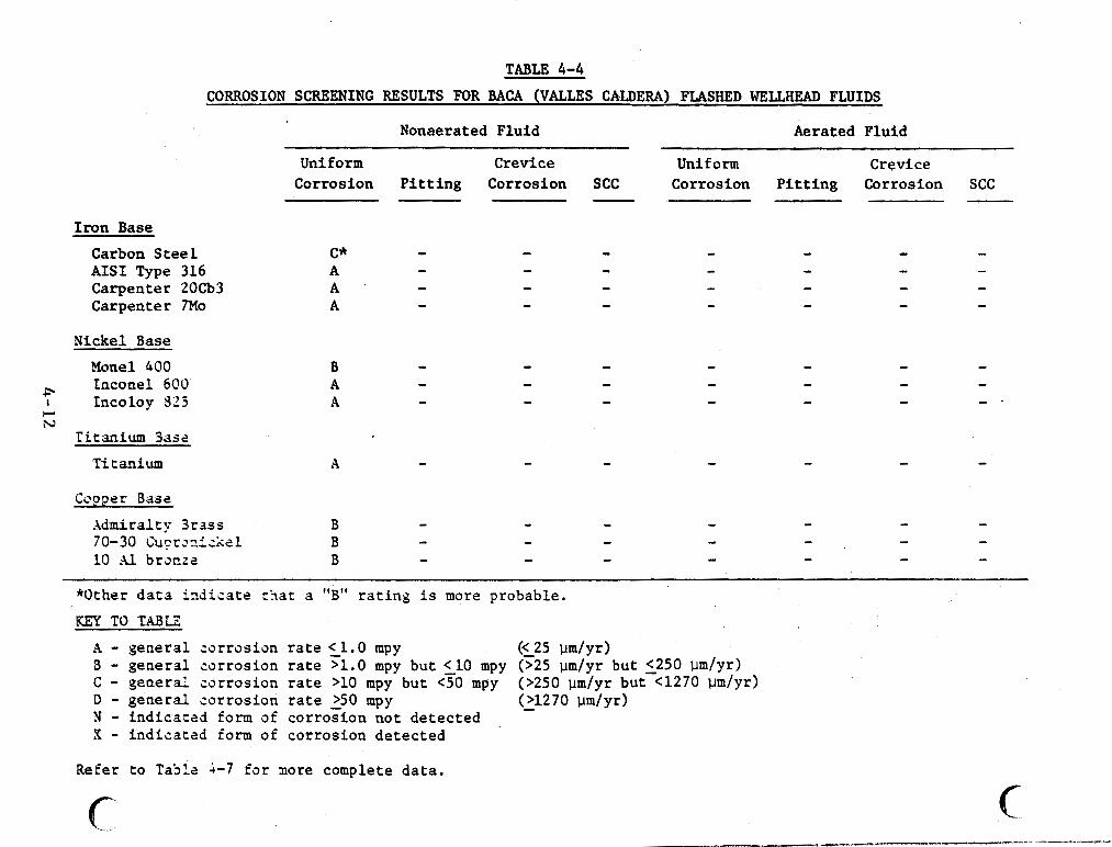
Iron Base
Carbon S t e e l AIS1 Type 316 Carpenter 20Cb3 Carpenter 7Mo
TABLE 4-4 CORROSION SCREENING RESULTS FOR BACA (VALLES CALDERA) FLASHED WELLHEAD FLUIDS
Nickel Base
Monel 400 Inconel 600 P
I Incoloy 825 w N
T i t a n i u m Base
Titanium
Copper Base
.\dmira.lty 3 r s s s 70-30 Cu?rx.l:Xel 10 Al brooza
Nonaerated Fluid
Uniform Crevice Corrosion P i t t i n g Corrosion SCC -
C* - A - A - A -
B - A - A -
A -
B - B - B -
Aerated Fluid
Uniform Crevice Corrosion P i t t i n g Corrosion SCC
*Other d a t a i z d i c a t e tSat a "B" r a t i n g i s more probable.
KEY TO T A B E
A - general corrosion r a t e 51.0 mpy B - general corrosion ra te >1.0 mpy bu t < 10 mpy (>25 pm/yr but <250 Um/yr) c - general corrosion rate >lo mpy but <TO mpy D - general corrosion ra te 250 mpy N - fndfcated form of corrosion not detected X - indicated form of corrosion detected
((25 w / y r )
(>250 pm/yr but'-<1270 pm/yr) (11270 wn/yr)
Refer to Tabla 1-7 f o r more complete da t a .
c- c
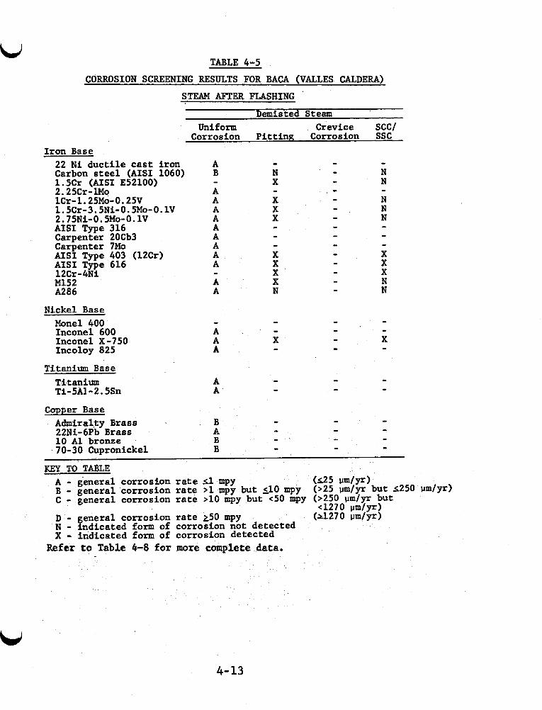
TABLE 4-5 CORROSION SCREENING RESULTS FOR BACA (VALLES CALDERA)
STEAM AFTER FLASHING
Demisted Steam Uniform Crevice SCC/
Corrosion Pitting Corrosion SSC Iron Base 22 Ni ductile cast iron Carbon steel (AISI 1060) 1.5Cr (AISI E52100) 2.25Cr-lMo lCr-l.25Mo-O.25V 1.5Cr-3.5Ni- 0.5Mo-0.1V
AISI Type 316 Carpenter 20Cb3 Carpenter 7Mo AISI Type 403 (12Cr) AISI Type 616 1 2Cr - 4N i M152 A286
2.75Ni-O.SMo-O.lV
Nickel Base Monel 400 Inconel 600 Inconel X -750 Incoloy 825
Titanium Base Titanium Ti-SA1 -2.5Sn
Copper Base Admiralfy Brass 22Ni-6Pb Brass 10 A1 bronze
~ 70-30 Cupronickel
A B
A A A A A A A A A
A A
-
-
- A A A
A A
B A B B
KEY TO TaLE A - general corrosion rate il mpy ( ~ 2 5 d y r ) B - general corrosion rate >lmpy but 510 mpy C - general corrosion rate >10 mpy but c50 mpy (>250 pm/yr but
(>25 um/yr but 2250 um/yr)
~1270 pm/yr) (A270 d y r ) eneral corrosion rate 250 mpy
N D - f - ndicated form of corrosion not detected X - indicated form of corrosion detected
Refer t o Table 4-8 for more complete data.
4-13
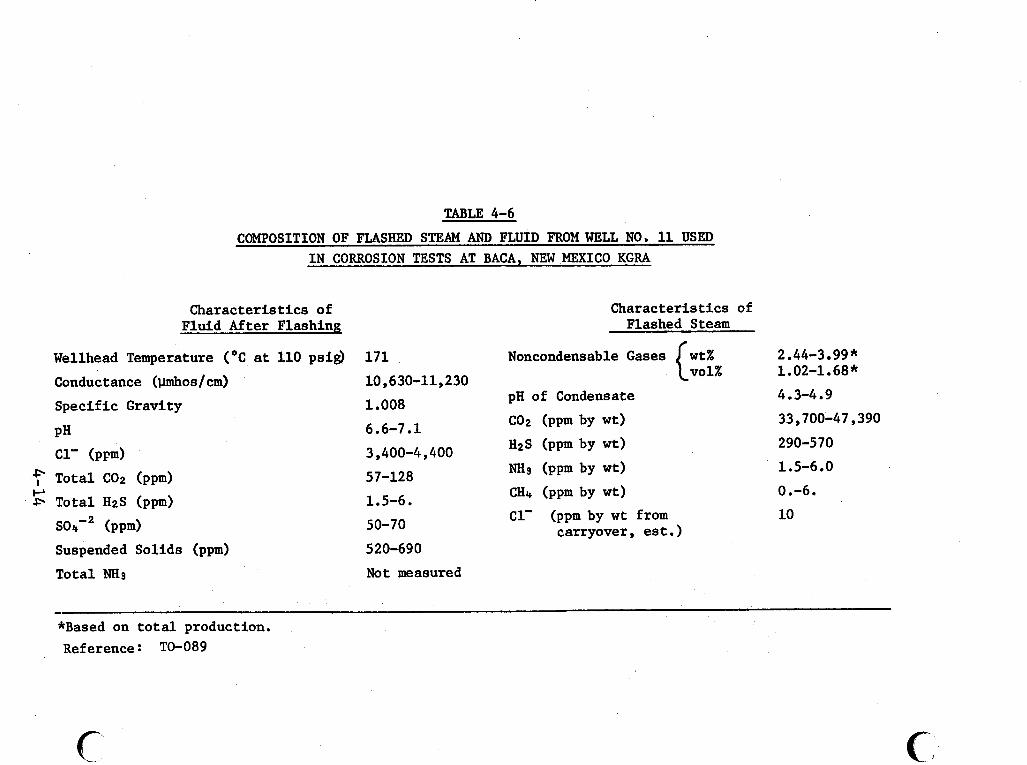
TABLE 4-6
COMPOSITION OF FLASHED STEAM AND FLUID FROM WELL NO, 11 USED I N CORROSION TESTS AT BACA, NEW MEXICO KGRA
Characteristics of Fluid After Flashing
Wellhead Temperature ("C at 110 ps i$
Conductance (pmhos/cm)
Spec i f ic Gravity
PH c1' (PFd Tota l COS (pprn)
Total H2S (pprn)
(PPd
Suspended Sol ids (pprn)
Tota l "3
1 7 1 10,630-11,230
1.008
6.6-7.1
3,400-4,400
57-128
1.5-6.
50-70
Characteristics of Flashed Steam
Noncondensable Gases w t %
pH of Condensate
CO2 (ppm by wt)
H2S (ppm by wt)
"3 (PPm by wt)
CH4 (ppm by wt)
C1' (ppm by w t from
c vol%
carryover, est.) 520-690
Not measured
2.44-3 99 * 1.02-1.68*
4.3-4.9
33,700-47,390
290-570
1.5-6.0
0.-6.
10
- *Based on t o t a l production. Reference : TO-089
6-
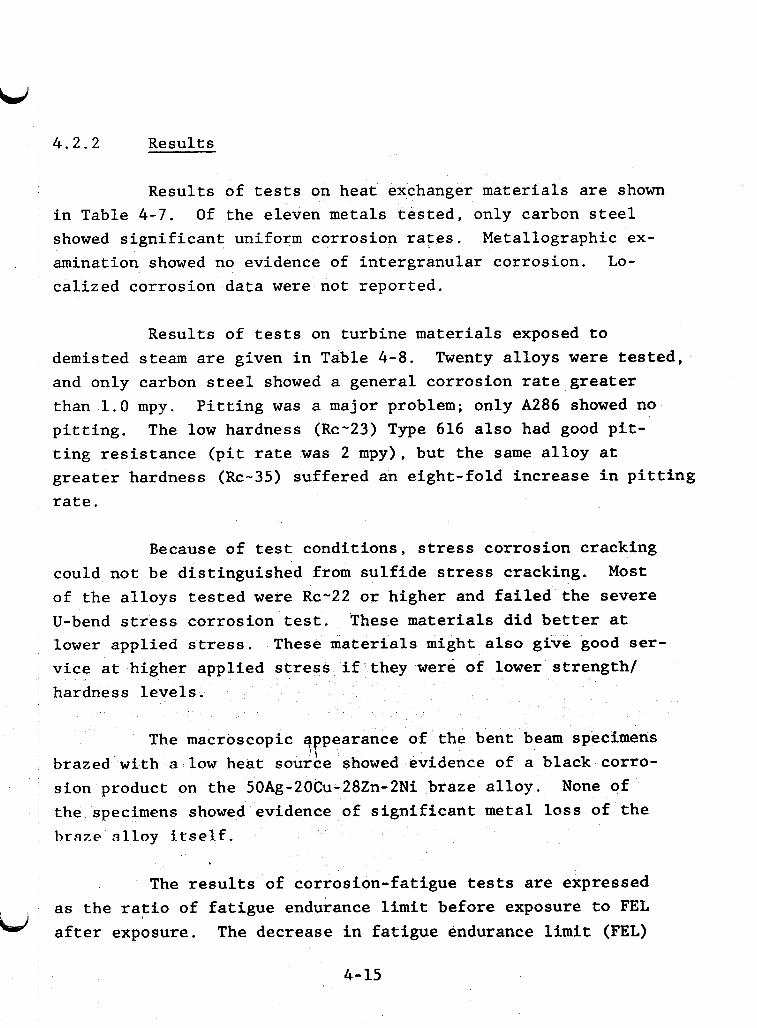
4.2.2 Results
Results of tests on heat exchanger materials are shown in Table 4-7. Of the eleven metals tested, only carbon steel showed significant uniform corrosion rates. amination showed no evidence of intergranular corrosion. Lo- calized corrosion data were not reported.
Metallographic ex-
Results of tests on turbine materials exposed to demisted steam are given in Table 4-8. and only carbon steel showed a general corrosion rate greater than 1.0 mpy. pitting. ting resistance (pit rate was 2 mpy), but the same alloy at greater hardness (Rc-35) suffered an eight-fold increase in pitting rate.
Twenty alloys were tested,
Pitting was a major problem; only A286 showed no The low hardness (Rc-23) Type 616 also had good pit-
Because of test conditions, stress corrosion cracking could not be distinguished from sulfide stress cracking. of the alloys tested were Rc-22 or higher and failed the severe U-bend stress corrosion test. These materials did better at lower applied stress. vice at higher applied stress if they were of lower strength/ hardness levels.
Most
These materials might also give good ser-
The macroscopic earance of the bent beam specimens brazed with a low heat source showed evidence of a black corro- sion product on the 50Ag-20Cu-28Zn-2Ni braze alloy. the specimens showed evidence of significant metal loss of the braze alloy itself.
YP None of
The results of corrosion-fatigue tests are expressed as the ratio of fatigue endurance limit before exposure to FEL
td after exposure. The decrease in fatigue endurance limit (FEL)
4-15
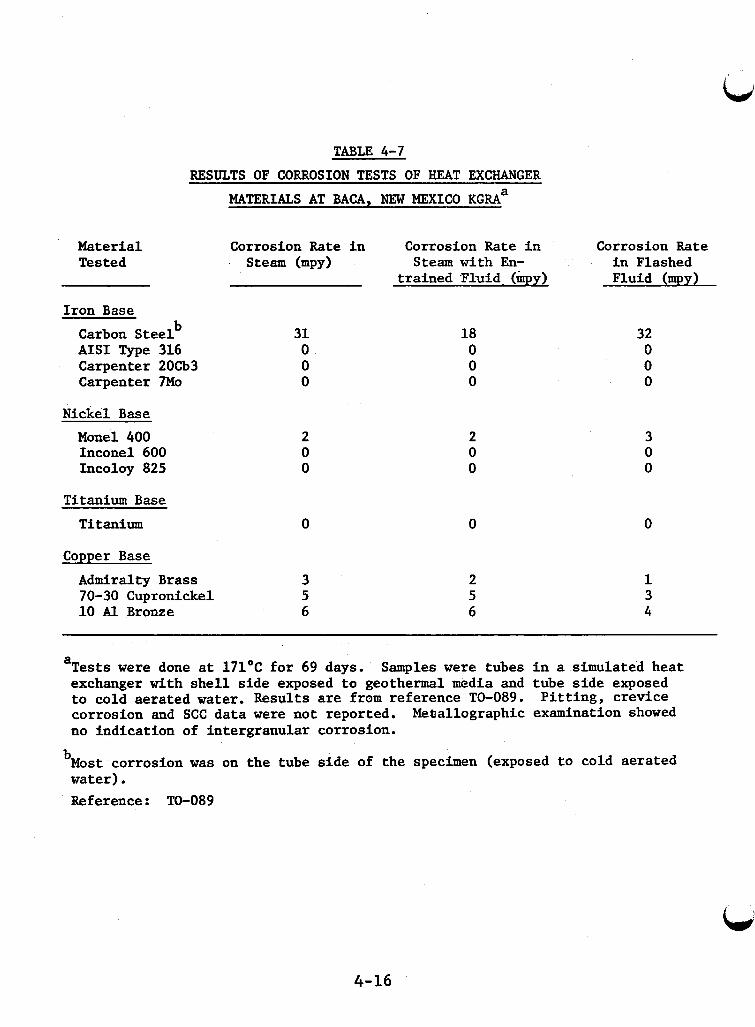
TABLE 4-7 RESULTS OF CORROSION TESTS OF HEAT EXCHANGER
MATERIALS AT ma, NEW MEXICO K G R A ~
Material Tested
Corrosion Rate i n Steam bPY)
Corrosion Rate i n Flashed Fluid (mpy)
Corrosion Rate i n Steam wi th En-
t r a ined Fluid (kpy)
I ron Base b Carbon S t e e l
AIS1 Type 316 Carpenter 20Cb3 Carpenter 7Mo
Nickel Base Monel 400 Inconel 600 Incoloy 825
31 0 0 0
18 0 0 0
32 0 0 0
2 0 0
3 0 0
2 0 0
Titanium Base
0 Titanium 0 0
Copper Base
Admiralty Brass 70-30 Cupronickel 10 Al Bronze
3 5 6
2 5 6
1 3 4
a Tests were done a t 171OC f o r 69 days. exchanger with s h e l l s i d e exposed t o geothermal media and tube s i d e exposed t o cold aerated water. Results are from reference TO-089. P i t t i n g , c rev ice corrosion and SCC da ta were not reported. no ind ica t ion of i n t e rg ranu la r corrosion.
Samples were tubes i n a simulated hea t
Meballographic examination showed
bMost corrosion w a s on t h e tube s i d e of t he specimen (exposed t o cold aera ted water). Reference: TO-089
4-16
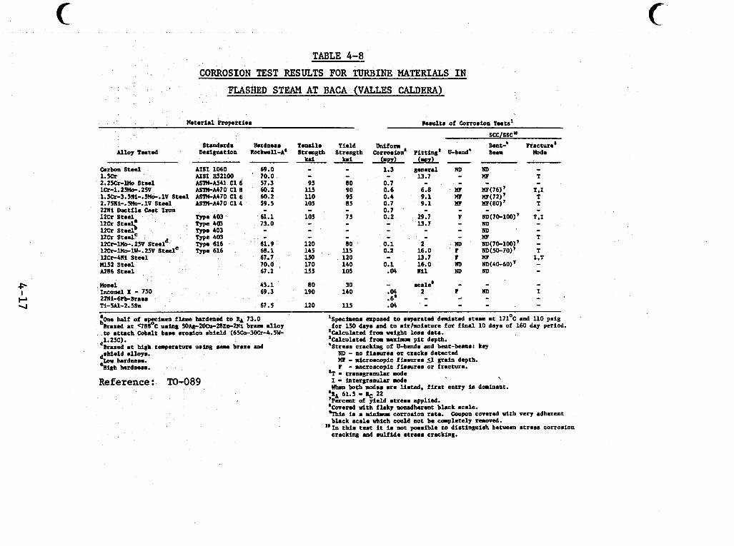
TABLE 4-8 CORROSION TEST RESULTS FOR TURBINE MATERIALS IN
FLASHED STEAM AT BACA (VALLES CALDERA)
Material Roper t ias Results of Corrosion Tests'
Standards Ihrdness T u u i l a Yield Alloy Tested Dwignation Rockwll-A' Strength Strength
hi hi -- Carbon Stee l AIS1 1060 69.0 - - 1.m U S 1 E52100 70.0 - - 2.2SCr-lllo Steal ASTM-AS41 C16 57.3 95 so lCr-1.2RIe.ZW ASlU-A470 C 1 8 60.2 115 90 1.5h-3.5Ni-.5?le.lV Steel ASlYkA470 C 1 6 60.2 110 95 2.75Ri-.5Mo-.lV Steel ASlM4470 C14 59.5 105 85
SCCISSC"
h i form B a t - ' Fracture' Corrosion' pit ti^' ll-bad' Bern mde
1.3 general RD ND - - 13.7 - n F T n t - - - -
L E ! P Y L A € ! L -
-. . 0.6 6.8 nF Wp(76)' T.1 0.4 9.1 M P ~ ( 7 2 ) ~ T 0.7 9.1 HF w(80)7 T
2mi Ikwtile cast Imn - - - 1 2 h S t r \ Type 40) 73.0 - - 12Cr S t m l Type 403 - - ucr SteelC - - -
61.9 120 80 68.1 145 U S
1?Cr-llb-.zm st 12Cr-1wO-lw-.2% S t 12Cr-4Ni Steel 67.7 150 120 11152 Steel 70.0 170 140 A286 Steel 67.2 155 105
I2Cr Steel. me 403 61.1 105 75
n d 43.1 Ineonel X - 750 69.3 2ZNi-6Pb-Brass Ti-W-2.5Sn 67.5
:Cue h l f of specben f l r a c hardaed t o RA 73.0 -
Brazed a t C)8EoC using 50Ag-200u-Z8En-2Ni b r a alloy to at tach Cobalt base erosion shield (65&3OCr4.5+
Brazed a t high temperature ruing ...c braze md ,1.25c).
Reference: TO-089
0.7 0.2 - - - 0.1 0.2
0.1 - .04
- 29.1 13.7 - -
2 16.0 13.7 16.0 nu
80 190
120
30 - scale' - - 140 .04 2 P w
.6' - - - 115 .04 - - -
' S p c f i m s exposed t o separated deds ted steam at 171'C a d 110 psi8
zCalcukted from Wight 1008 &ta. 'Calculated f m mlmm p i t depth. 'Stress c r a c k i q of U-bends and beut - lwu: key
ND - no f i ssures or cracks detected M - microscopic fimsurea S I grain depth. I - M C ~ O O C O P ~ C f issures or fracture.
for 150 days and t o air/moisture for f i n a l 10 days of 160 day period.
'T - transgranular mode I - intergranular d e \
When both d e s are listed. f i r s t entry i. dominant. %A 61.5 - 22 ' ~erceut of viem stream aoulied. 'Covered w i t i flaky nonadh&ent black scale. 'This is a minina corrosion rate. Coupon covered with very adherent black scale which could not be completely raoved.
cracking and .ulfi.de stress cracking. "In this test it in not possible t o distinguish betunm s t reas corrosion
c
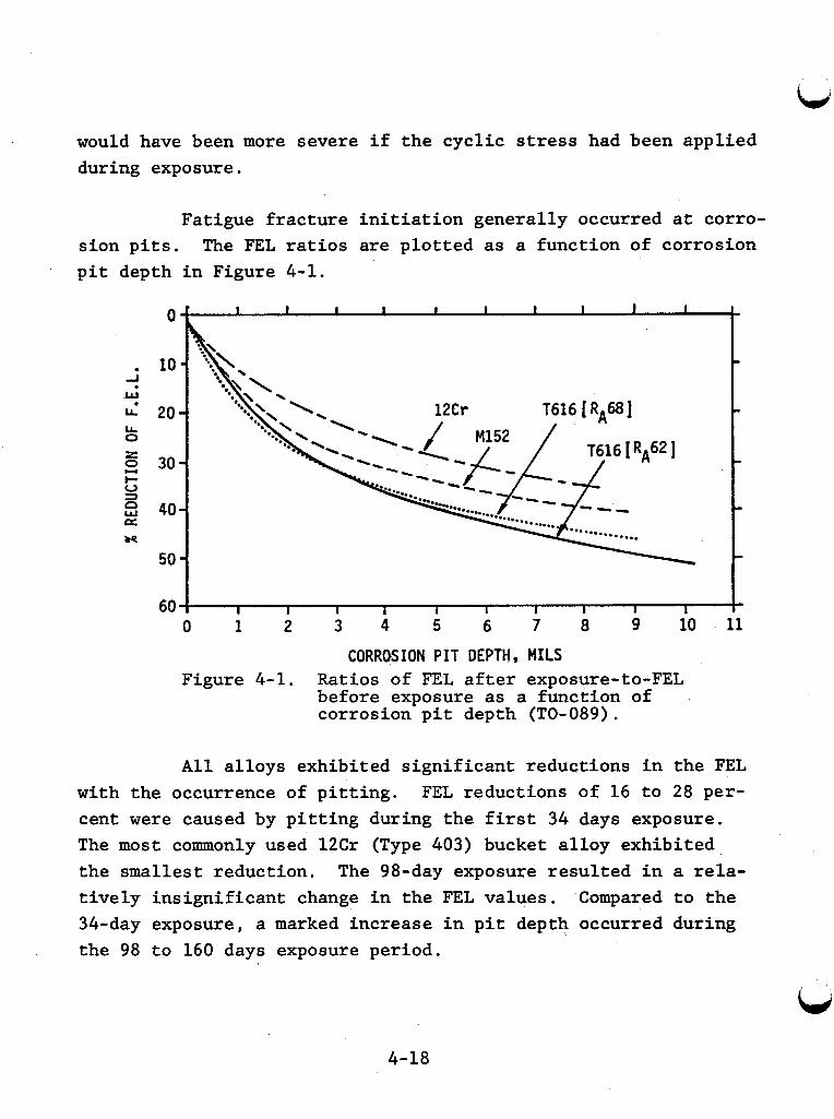
would have been more severe if the cyclic stress had been applied during exposure.
Fatigue fracture initiation generally occurred at corro- sion pits. pit depth in Figure 4-1.
The FEL ratios are plotted as a function of corrosion
- -
40 - m
50 - 60 I I I I I I I I I 10 I 11 I
9 0 1 2 3 4 5 6 7 8
CORROSION PIT DEPTH, MILS Figure 4-1. Ratios of FEL after exposure-to-FEL
before exposure as a function of corrosion pit depth (TO-089).
All alloys exhibited significant reductions in the FEL with the occurrence of pitting. FEL reductions of 16 to 28 per- cent were caused by pitting during the first 34 days exposure. The most commonly used 12Cr (Type 403) bucket alloy exhibited the smallest reduction. tively insignificant change in the FEL values. Compared to the 34-day exposure, a marked increase in pit depth occurred during the 98 to 160 days exposure period.
The 98-day exposure resulted in a rela-
4-18
A t the end of the f i n a l exposure, FEL values were re- duced 36 t o 52 percent. With p i t t i n g t o a depth of approximately 9 t o 10 mils, the FEL r a t i o s of Type 616 hea t t rea ted to "low" and "high" hardness levels were lowered approximately 50 percent. The two low t e n s i l e s t rength a l loys , Type 403 (RA 61) and Type 616 (RA 62) , did not exhib i t the same reductions i n FEL fo r com- parable corrosion p i t depths. hardness levels, the Type 403 i s less notch sens i t i ve i n fa t igue than the Type 616.
This suggests t h a t a t comparable
4- 19
-
L,
4.3 Results of Corrosion Tests at East Mesa, California KGRA
Summarized "screening" results of field corrosion tests in East Mesa fluids are given in Tables 4-9 (wellhead fluid), 4-10 (first flash liquid), 4-11 (second flash liquid), 4-12 (first flash steam), and 4-13 (second flash steam). Field tests were conducted after preliminary laboratory testing with wellhead fluid. The field tests are short duration tests and should be used cautiously, but they are useful as guidelines. Additional field tests are underway at East Mesa.
4.3.1 Description of Test Streams
Corrosion tests were conducted in five different streams from well Mesa 6-1. This well contains higher concentrations of corrosive species than later wells drilled at East Mesa and repre- sents worst case conditions for this KGRA. Table 4-14 gives de- tailed analyses of Mesa 6-1 and Cerro Prieto wellhead fluids. Cerro Prieto data are included with the East Mesa because of the proximity and similarity of the two sites. This similarity should enable some corrosion data from Cerro Prieto to be extrapolated to East Mesa. The lab 6-1 data are the compositions of solutions taken at well Mesa 6-1 and used in laboratory corrosion studies.
The wellhead fluid in the in situ tests was a two-phase -- mixture because the geothermal fluid flashed in the bore of the well. tor and produced the first flash liquid and steam streams where in situ testing was conducted. Additional in situ corrosion test- ing was conducted in second flash streams after passing through another separator. The compositions of the five in situ test streams are compared in Table 4-15 (NE-302).
The fluid from the wellhead then passed through a separa-
-- --
--
4-20
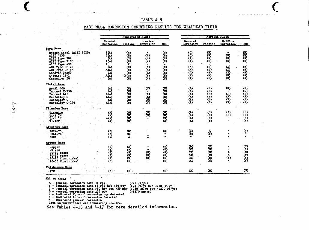
-... . I
. . . . " . ~ - ~ . -. I. ~ -. - . ._ . ... . .. " .__ . . .. -. .. .. .- . . . . ... . . . . . . . . . . . . . ... . " - . . . , , .
C c TABLE 4-9
EAST MESA CORROSION SCREENING RESULTS FOR WELLHEAD FLUID
Nonaera ted F l u i d Aerated F l u i d
Cor ros ion P i t t i n g Cor ros ion SCC Cor ros ion P i t t i n g Cor ros ion SCC General Crev ice Genera l Crev ice
I r o n Base
N i c k e l Base Hone1 400 I n c o n e l X-750 I n c o n e l 625 H a s t e l l o y S H a s t e l l o y G H a s t e l l o y C-276
Titanium Base Ti t an ium Ti-1.7W Ti-1 .581 Ti -1OV
Aluminum Base 2024-T3 6061-T6 5005
Copper Base Cop er cu-%e 90-10 Brass 70-30 B r a s s 90-10 Cupron icke l 70-30 Cupron icke l
Molybdenum Baee - (B) (N) - (N) TZH (A) (N) (N)
KEY TO TABLE A - g e n e r a l c o r r o s i o n r a t e sl mpy B - g e n e r a l c o r r o s i o n r a t e >1 mpy but d o mpy C - g e n e r a l c o r r o s i o n r a t e > l o mpy but <50 mpy (>250 um/yr but (1270 pm/yr) D - g e n e r a l c o r r o s i o n rate G O mpy N - i n d i c a t e d form of c o r r o s i o n n o t d e t e c t e d X - i n d i c a t e d form of c o r r o s i o n d e t e c t e d * - i n c r e a s e d g e n e r a l c o r r o s i o n Data i n p a r e n t h e s e s a r e l a b o r a t o r y results.
(125 um/pr) (>25 &yr b u t d 5 0 m / y r )
( > I 2 7 0 um/yr)
See T a b l e s 4-16 and 4-17 for mare detailed information.
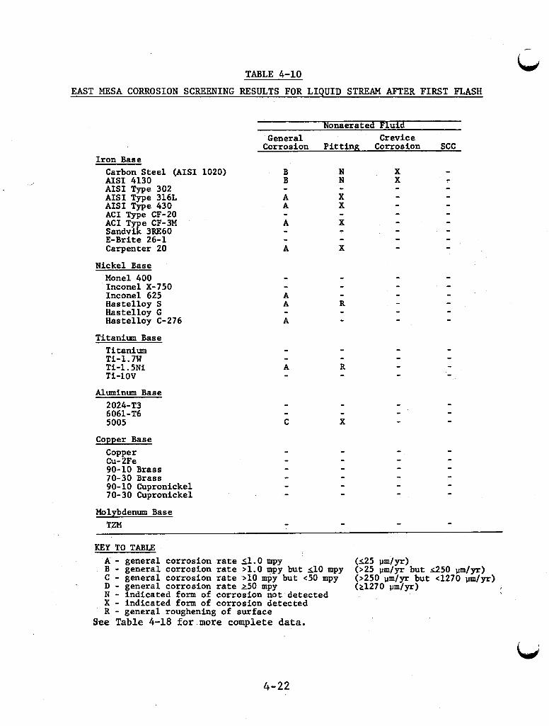
L TABLE 4-10
EAST MESA CORROSION SCREENING RESULTS FOR LIQUID STREAM AFTER FIRST FLASH
Nonaerated Fluid General Crevice
Corrosion Pitt ing Corrosion SCC Iron Base
Carbon Steel (AISI 1020) AISI 4130 A I S I Type 302 AISI Type 316L A I S I Type 430 A C I Type CF-20 A C I T e CF-3M Sandvz 3RE60 E-Brite 26-1 Carpenter 20
Nickel Base Monel 400 Inconel X-750 Inconel 625 Hastelloy S Hastelloy G Hastelloy C-276
Titanium Base Titanium Ti-1.7W Ti -1 .5Ni T i - 1 O V
Aluminum Base 2024-T3 6061-T6 5005
Copper Base Copper Cu- 2Fe 90-10 Brass 70-30 Brass 90-10 Cupronickel 70-30 Cupronickel
Molybdenum Base TZM
N N
X X
X
- - c - X
KEY TO TABLE A - general corrosion rate 51.0 mpy B - general corrosion rate >1.0 mpy but 110 mpy C - general corrosion r a t e >lo mpy but <50 mpy D - general corrosion ra te 250 mpy N - indicated form of corrosion not detected X - indicated form of corrosion detected R - general roughening of surface
See T a b l e 4-18 for more complete data.
4-22
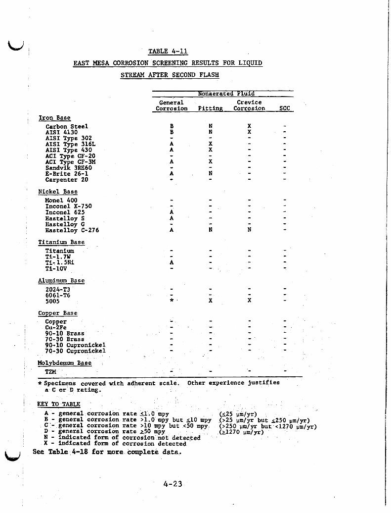
!
TABLE 4-11
EAST MESA CORROSION SCREENING RESULTS FOR LIQUID
STREAM AFTER SECOND FLASH
Nonaerated Fluid
Iron Base Carbon Steel AISI 4130 AISI Type 302 AISI Type 316L AISI Type 430 ACI Type CF-20 ACI Type CF-3M Sandvik 3RE60 E-Brite 26-1 Carpenter 20
Nickel Base Monel 400 Inconel X-750 Inconel 625 Hastelloy S Hastelloy G mstel loy C-276
Titanium Base Titanium Ti-1.7W Ti- 1.5Ni Ti- 1OV
Aluminum Base 2024-T3 6061-T6 5005
General Crevice Corrosion Pitt ing Corrosion SCC
X X -
Copper Base
Cu- Fe 90-10 Brass 70-30 Brass 90-10 Cupronickel 70-30 Cupronickel
I - - - - - - - - - - - - - - - - - - - - - - - - Molybdenum Base 1
I - I TZPl - - 1 Specimens covered with adherent scale. Other experience jus t i f ies 1 a C o r D rating. I
KEY TO TABLE I
I A - general corrosion rate (1.0 mpy B - general corrosion rate >1.0 mpy but 510 mpy
I C - general corrosion rate >10 mpy but <50 mpy I D - general corrosion r a t e 250 mpy (21270 p m / y r )
N - indicated form of corrosion not detected X - indicated form of corrosion detected
,(>25 pm1y-r but 2250 p m / y r ) (>250 pm/yr but <1
See Table 4-18 for more complete data. BLd ~
4 - 2 3
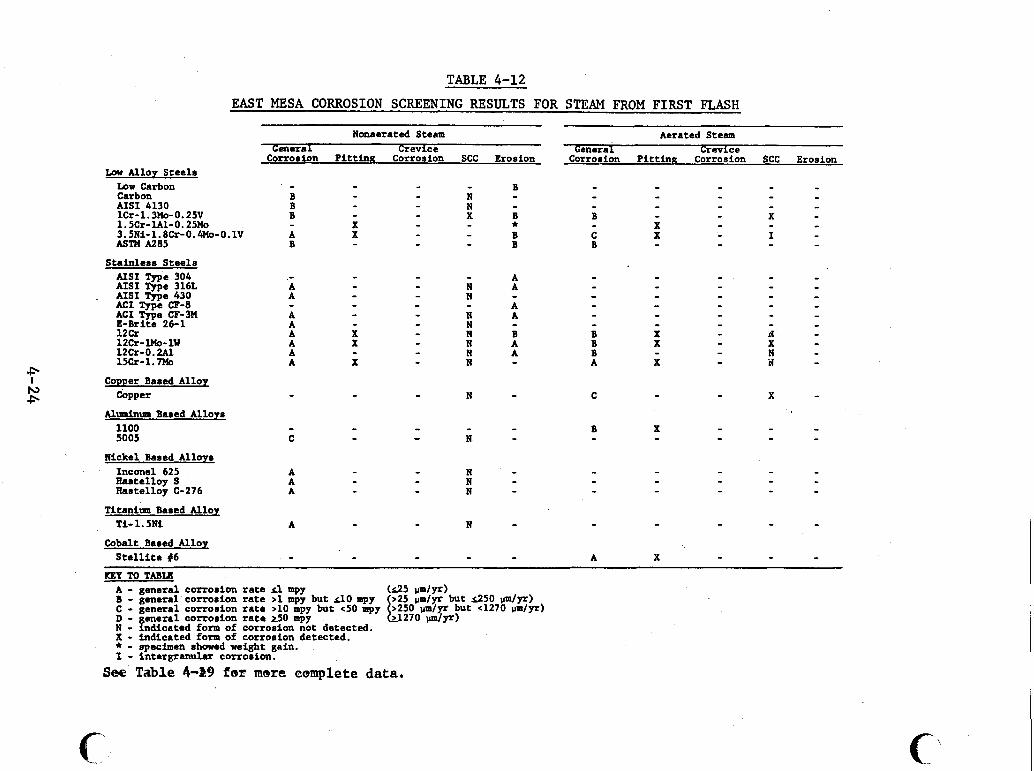
TABLE 4-12
EAST MESA CORROSION SCREENING RESULTS FOR STEAM FROM FIRST FLASH
Nonaerated Steam Aerated Steam General Crevice General Crevice Corrosion Pitting Corrosion SCC Erosion Corrosion Pitting Corrosion SCC Erosion
Lcno Alloy Steels - - Low Carbon B - - Carbon B N - - - - - AISI 4130 B N - - - - - 1Cr- 1.3%- 0.25V B X B B X - 1.5Cr-lA1-0.25Mo X X - 3.5Ni-1.8Cr-0.4Mo- 0.1V A X B C X I - ASTH A285 B B B - - -
AISI Type 304 - - - - - - - - N A - N
AISI Type 316L A . AISI Type 430 A - - - - -
ACI Type CF-8 A - - - - - ACI Type CF-3M A N A - - - - E-Brita 26-1 A N - - - - - -
d X
X N B B X N A B X
12cr A 12cr-1PIo-lW A X -
N N
12cr-0.2A1 A N A B 15cr-1.m A X N A X -
- - - - - - - - * - - - - - Stainless Steels
A - - - - - - - - - - - - - - - - - - - - - - - - - - - Comer Based Alloy - - - - - - Cbpper N C X - Aluminum Based Alloys 1100 - - - - - 5005 C - - N -
Nickel Based Alloys - Inconel 625 A N - - - Raatelloy S A N - - - - Rastelloy C-276 A N - - - - -
Ti- 1.511 A N - - -
- - - - - Titaniwn Based Allox
- - - - - Cobalt Based Allor - - - - - Stellitc #6 A X - KEY TO TABU A - general corrosion rate 3 mpy B - general corrosion rate >l mpy but do mpy C - general corrosion rate >10 mpy but <50 mpy (>250 p m / p but ~1270 p m / p ) D - general corrosion rate G O mpy N - indicated form of corrosion not detected. X - indicated form of corrosion detected. * - npecimcn showed weight gain. t - intergmlar carrosion.
k.25 pmmlyrr)
(L1270 run l~ ) (>25 pm/yr but ~ 2 5 0 pmlyr)
See Table 4-39 fer mere complete data.
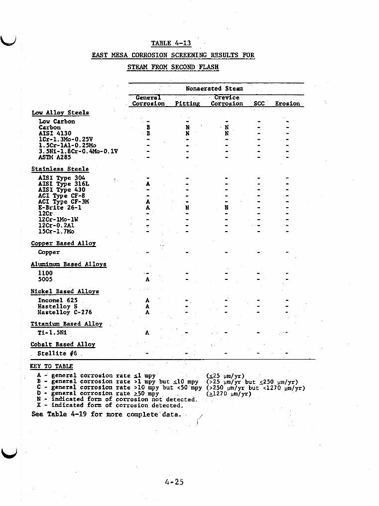
Low Alloy Steels Low Carbon Carbon
TABLE 4-13 EAST MESA CORROSION SCREENING RESULTS FOR
STEAM FROM SECOND FLASH
AISI 4130 lCr-1.3Mo-0.25V 1.5Cr-lAl-O.25Mo 3.5Ni-l.8Cr-0.4Mo-O.lV ASTM Has
Stainless Steels AISI Type 304 AISI Type 316L AIS1 Type 430 A C I Type CF-8 ACI Type CF-3M E-Brite 26-1 12Cr 12Cr- lMo- 1W 12Cr-0.2A1 15Cr-1.7Mo
Copper Based Alloy Copper
Aluminum Based Alloys 1100 5005
Nickel Based Alloys Inconel 625 Hastelloy S Hastelloy C-276
Titanium Based Alloy Ti - 1 5Ni
Cobalt Based Alloy S t e l l i t e 46
Nonaerated Steam General Crevice
Corrosion Pittinp; Corrosion SCC Erosion
~~ ~
KEY TO TABLE A - general corrosion rate 11 mpy B - general corrosion r a t e >1 mpy but 110 mpy C - general corrosion r a t e >lo mpy but <50 mpy (>250 pm/yr but ~ 1 2 7 0 p m / y r ) D - general corrosion r a t e 250 mpy N - indicated form of corrosion not detected. X - indicated form of corrosion detected.
See Table 4-19 for more complete data.
(125 W y r ) (>25 pm/yr but 2250 prn/yr)
(21270 d y r )
1 I
4-25
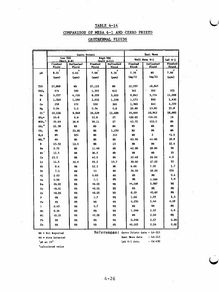
.b
PH '
TDS
si02
Na
K Ca
ng c1-
s o p HCO, - c o r - C O P HIS LWr +
B
Ba
B r ' CS
L i Rb
Sr
Al AS
B e
co
C r
F Fe
I
h N i
Pb Zn
TABLE 4-14
COMPARISON OF MESA 6-1 AND CERRO P R I E T O
GEOTHERMAL FLUIDS
Cerro L w TDS
Plashed Fluid
I 8.21
(ppm)
17,068
974
5,257
1,310
258
0.04
10,128
10.0
32.49
11.38
NR NR NR
15.52
5.72
12.5
25.5
14.5
8.4
7.3
0.03 0.06
e0.03
(0.01
<0.05
NR
NR 0.45
0.04
(0.01
NR NR
NR - Not Reported
ND - None Detected
'pH a t 25'
'calculated value
B) if lashed Fluid
5.43 2
( P P I
NR 590
4,730 1,180
272
0.2
9.040
9.p 38.0 NR
25.80
624 NR
12.0
NR NR NR
10.9
NR NB NR NR NR
NR NR NR NR NR NR
NR
NR NR
Leto High TDS 3 Flashed
Fluid
7.90 I
( P P I
27.123
1.345
8,229
2,032
550 0.34
16,129
12.0
59.11
ND NR NR NR NR
11.48
36.5
40.9
25.2
12.3
15
0.03 1.1
<0.03
so.01 (0.05
1.7
NR 0.7
NR
(0.01
NR NR
11) Inflashed
Fluid
5.34
(PPd
2
NR 610
5,600
1 , 230
369 0.8
11.400
27
27
NR 1.250
310
NR
13 NR
NR
NR 13.7
NR NR NR w NR
NR NR NR NR
NR NR
NR
m NR
East &sa
Well Mom 6-1 Flashed
Fluid
7.70 I
(mg/l)
32,250
341
9.845
1,173
1,360
20,80
19,400
<20.00
45.70
ND ND NR
83.00
NR 42.00
NR 12.40
30.00 6.00
56.00
NR NR
<0,004
NR 0,03
1.60
0,250
NR 1.260
NR
0.200
40, a05
Unflashed Fluid
NR (mg/l)
18.847
300
5.774
898
642
13.80
10,942
<10.00 223.0
NR NR 3
41.00
NR 18.00
NR 26.00
37.00
7.20
58.00
NR 0.009
0.007
NR <0,02
1.23
3.40
NR
0.95
0.10
a , io 0.17
References : Cerro P r i e t o da ta - LA-312
East Mesa d a t a - LA-312
Lab 6-1 d a t a - CA-430
4-26
k b 6-1 Flashel Fluid
1 7.60
(PPd
101
11 $000
1,430
1,370 21.8
18.000
16
NR NR NR
a . 0
38.8
22.4
58
35
4.0
55
1.7
226
0.4 1 ,o NR
NR NR 1.5
0.18
NR 0.9
w 0.20
0.02
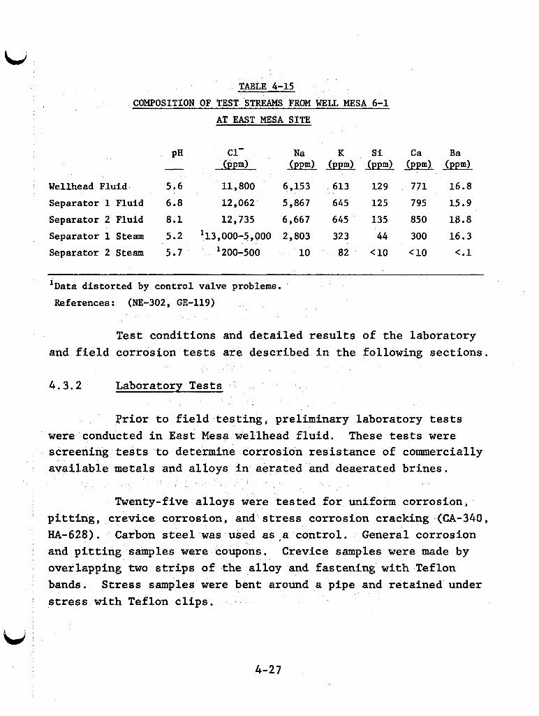
TABLE 4-15
COMPOSITION OF TEST STREAMS FROM WELL MESA 6-1
AT EAST MESA SITE
PH c1- Na K si C a Ba - 0 OOk m) ( P P ~ X ( P P ~ )
Wellhead Fluid 5.6 11,800 6,153 613 129 771 16.8
Separator 1 Fluid 6.8 12 062 5,867 645 125 795 15.9
Separator 2 Fluid 8.1 1 2 735 6,667 645 135 850 18.8 Separator 1 Steam 5.2 113,000-5,000 2,803 323 44 300 16.3
Separator 2 Steam 5b7 200-500 10 82 < l o <10 c.1
' D a t a d i s t o r t e d by con t ro l valve problems.
References: (NE-302, GE-119)
Test conditions and detailed results of the laboratory and field corrosion tests are described in the following sections.
4 . 3 . 2 Laboratory Tests
Prior to field testing, preliminary laboratory tests were conducted in East Mesa wellhead fluid. These tests were screening tests to determine corrosion resistance of commercially available metals and alloys in aerated and deaerated brines.
Twenty-five alloys were tested for uniform corrosion, pitting, crevice corrosion, and stress corrosion cracking (CA-340 , HA-628). Carbon steel was used as,a control. General corrosion and pitting samples were coupons. overlapping two strips of the alloy and fastening with Teflon bands. stress with Teflon clips. .
Crevice samples were made by
Stress samples were bent around a pipe and retained under
4-27
The laboratory test solution was obtained from a sam- ple of wellhead fluid from well Mesa 6-1, this solution is given in Table 4-14.
The composition of
The laboratory tests wete useful for establishing guidelines and identifying potential problems, but they did not directly simulate actual site conditions for the following rea- sons :
1. Laboratory test temperatures (105°C) were lower than wellhead temperatures (130°C).
2. Laboratory solutions did not contain non- condensable gases.
3. The pH of the laboratory solution was less than that of the natural wellhead fluid.
Laboratory tests were run at 105°C for 15 days in aerated and deaerated media. Aeration was by constant air bubbling, and deaeration was by continuous helium purge. The noncondensable gases (Con, HzS, " 3 , etc.) were removed by the flashing and the purging. and carbonate species were also probably lower in the laboratory fluid than in the actual wellhead fluid because gaseous H2S and CO2 were lost in the flashing and purge gas. (6-7) was less acid than the actual wellhead brine which was about 5 . 7 .
The concentrations of sulfide
The solution pH
The results of the laboratory tests are presented in Tabel 4-16. General field corrosion results are also listed to compare with laboratory results of the same test duration, 15 days.
4-28
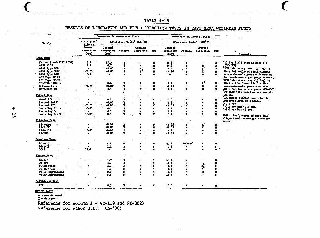
c TABLE 4-16
RESULTS OF LABORATORY AND FIELD CORROSION TESTS I N EAST MESA WELLHEAD FLUID
Carbon St..l(AISI 1020) 3.2 17.3 AIS1 4UO 1.9 0.2 AIS1 Typa 302 AISI Typa 316L AISI Type 430 ACI CF-20 ACI Typm CF-311 Saadrit 3lWO &Brit. 2 6 1 carpcater 20
- e0.05 co.05 <0.05
0.1 - - - 0.4
go. 05 <0.05 - 0.1
n n R n n n
n 40.9 n 10.7 n 0.1 n (0.05 - n 0.1 n <0 .8 n 0.2
n n I
nic*.i h a 0 .d.Pfh* - I n c n u r d general corrorion in fatreaaad arm of +bends, e0.1 my.
nand 4m 0.2 n n n 2.5 n I 1roal x-750 (0.05 n n 0.1 n fncoasl 625 <0.05 e0.m n R R e0.05 N' n G.1 epy but e l .0 .py. R..talloy s eo. 05 0.1 n N n 0.1 N n h>l.O q y but <5 mpy. 8.atUloy 0 0.1 n R 11 0.1 n N n
- - - - *
IQ 8 . s t m l l o y 0-276 <O. 05 0.1 R n N 0.1 n n I - N NOTE: Perfo-ec of umt (MI)
alloy. baaed 011 wrought counter pert.. Titanium Ban
T i m i r n Ti-1.m T i d . m i TI-1W
Alraina Barn 202CT3 6061-T6 5005
- Q.05 R eo. 05 n
<O. 05 go. 05 n eo. 05 n
- -
II n n n
n - N
X f N
0.1 n N
<0.05 n g0.05 n N n <0.05 N n
- -
Cower Baa4
cu-n. 9 b l O kru.
- - - 1.9 N N 63.1 N N - - 3.7 n I 11.6 n
90-10 cupronickel 0.9 N n n 3.7 N n n 70-30 cupronickel 5.7 n n 17.9 N N
TP( 0.2 n N 3.0 n n
copper - N 70-30 Drama - 1.2 2.2 n R n N N n 3.6 4.3 n i $ : - - - -
Molybdenum &M
- - - QI TO TABLE R - not detected. X - detect&.
Reference for column 1 - GE-119 and NE-302) Reference f o r o the r data: CA-430)
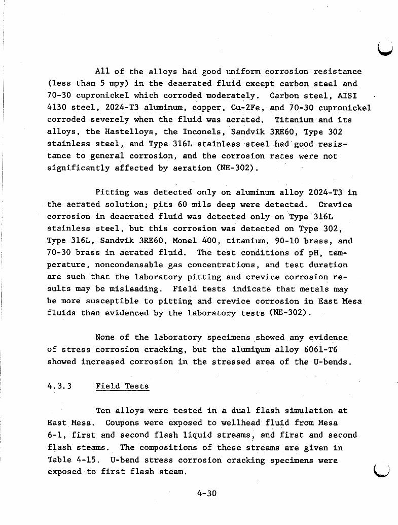
A l l of the alloys had good uniform corrosion resistance (less than 5 mpy) in the deaerated fluid except carbon steel and 70-30 cupronickel which corroded moderately. Carbon steel, AIS1 - 4130 steel, 2024-T3 aluminum, copper, Cu-2Fe, and 70-30 cupronickel corroded severely when the fluid was aerated, alloys, the Hastelloys, the Inconels, Sandvik 3RE60, Type 302 stainless steel, and Type 316L stainless steel had good resis-
Titanium and its
tance to general corrosion, and the corrosion rates were not significantly affected by aeration (NE-302).
Pitting was detected only on aluminum alloy 2024-T3 in the aerated solution; pits 60 mils deep were detected. corrosion in deaerated fluid was detected only on Type 316L stainless steel, but this corrosion was. detected on Type 302, Type 316L, Sandvik 3RE60, Monel 400, titanium, 90-10 brass, and 70-30 brass in aerated fluid. The test conditions of pH, tem- perature, noncondensable gas concentrations, and test duration are such that the laboratory pitting and crevice corrosion re- sults may be misleading. Field tests indicate that metals may be more susceptible to pitting and crevice corrosion in East Mesa fluids than evidenced by the laboratory tests (NE-302).
Crevice
None of the laboratory specimens showed any evidence of stress corrosion cracking, but the alumiQum alloy 6061-T6 showed increased corrosion in the stressed area of the U-bends.
4.3.3 Field Tests
Ten alloys were tested in a dual flash simulation at Coupons were exposed to wellhead fluid from Mesa East Mesa.
6-1, first and second flash liquid streams, and first and second flash steams. Table 4-15. U-bend stress corrosion cracking specimens were exposed to first flash steam.
The compositions of these streams are given in
4-30
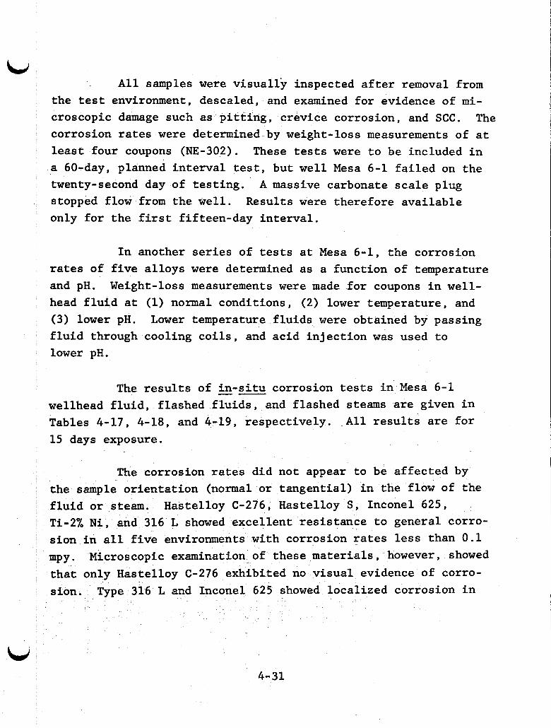
All samples were visually inspected after removal from the test environment, descaled, and examined for evidence of mi- croscopic damage such as pitting, crevice corrosion, and SCC. The corrosion rates were determined by weight-loss measurements of at least four coupons (NE-302). These tests were to be included in a 60-day, planned interval test, but well Mesa 6-1 failed on the twenty-second day of testing. A massive carbonate scale plug stopped flow from the well. Results were therefore available only for the first fifteen-day interval.
In another series of tests at Mesa 6-1, the corrosion rates of five alloys were determined as a function of temperature and pH. Weight-loss measurements were made for coupons in well- head fluid at (1) normal conditions, (2) lower temperature, and (3) lower pH. Lower temperature fluids were obtained by passing fluid through cooling coils, and acid injection was used to lower pH.
The results of -- in-situ corrosion tests in Mesa 6-1 wellhead fluid, flashed fluids, and flashed steams are given in Tables 4-17, 4-18, and 4-19, respectively. All results are for 15 days exposure.
The corrosion rates did not appear to be affected by the sample orientation (normal or tangential) in the flow of the fluid or steam. Hastelloy C-276, Hastelloy S, Inconel 625, Ti-2% Ni, and 316 L showed excellent resistance to general corro- sion in all five environments with corrosion rates less than 0.1 mpy. Microscopic examination of these materials, however, showed that only Hastelloy C-276 exhibited no visual evidence of corro- sion. Type 316 L and Inconel 625 showed llocalized corrosion in
I ,
I I
i I L, ,
4-31 I
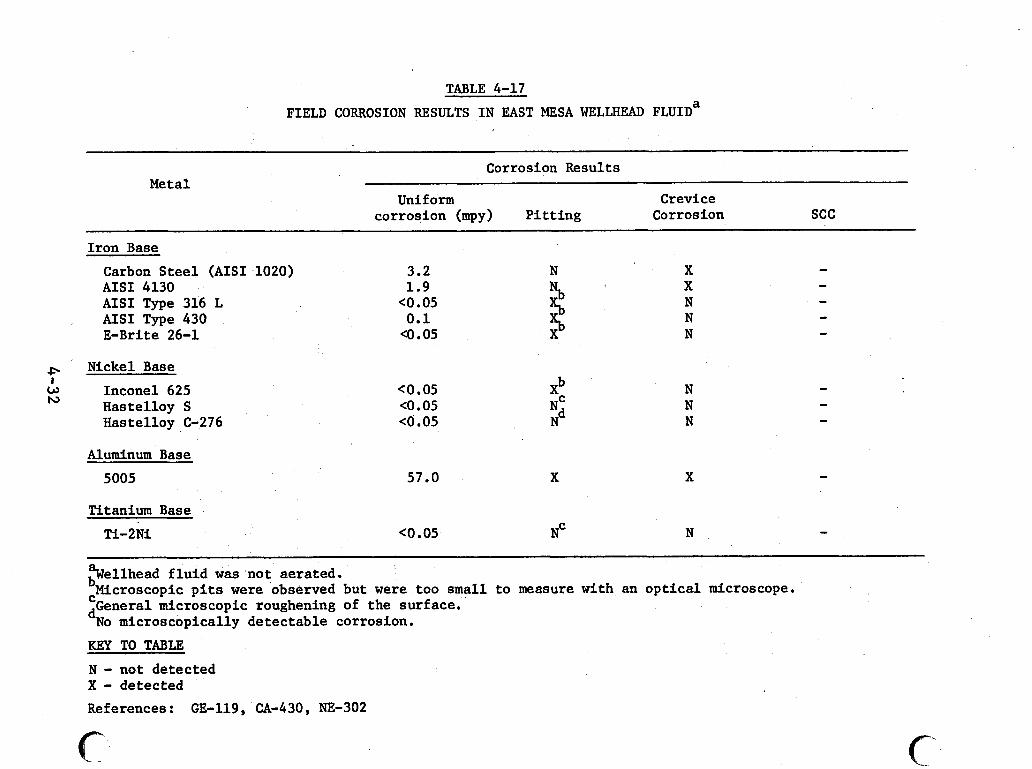
TABLE 4-17
FIELD CORROSION RESULTS IN EAST MESA WELLHEAD FLUID^
Metal Corrosion Results
Unif o m Crevice corrosion (mpy) P i t t i n g Corrosion SCC
Iron Base
Carbon S t e e l (AISI 1020) AISI 4130 AISI Type 316 L AISI Type 430 E - B r i t e 26-1
+. Nickel Base
w Inconel 625 Hastelloy S Hastelloy C-276
1
N
Aluminum Base
5005
Titanium Base
Ti-2Ni
3.2 1.9
<O .05 0.1
4 . 0 5
c0.05 <O .05 c0.05
57.0
c0.05
N
2 x, X
b ' xC 3 X
NC
N N N
X
N
%ellhead f l u i d w a s no t aerated. bMicroscopic p i t s were observed but were too small t o measure with an o p t i c a l microscope.
dNo microscopically de tec tab le corrosion.
KEY TO TABLE
N - not detected X - detected
References: GE-119, CA-430, NE-302
General microscopic roughening of the surface. C
c c
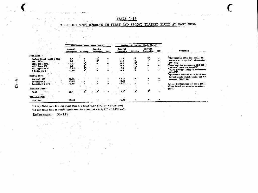
P I w w
TABLE 4-18
CORROSION TEST RESULTS IN FIRST AND SECOND FLASHED FLUID AT EAST MESA -
- kicro.copic pi t . too .la11 to measure d t h optical micrometer - - - b(NE-302).
3.3 N 1.2 N 0.1 0.2 0.1 - n 0.1
- S o u crevice corrodm (NE-302). - - - :Severe" pitting (NE-302). V e r y .evere" crevice c o ~ ~ o . i o n (NE-302).
'SpecLam covered vith h r d .d- ~ i c k e l mar - - herent Kale vhich could not be
Note: Puforunce of cast (MI) alloy b a e d on wrought counter- part.
f 2.4 n 1.6
0.5 - - - t
AIS1 4UO U S 1 Type 3161 (0.05 M S I Type 430 ACI Type CT-M c0.05 klhite 26-1 C0.05 t
- r s o ~ r d (GE-US). - (0.05 ( 0 . 0 - - - - - - - - - - - <0.05 <0.05
I n c d 625 Butalloy s b a t e l l o y 0.276
<0.05 (0.05
P - 2.1. f 21.4 z P -
(0.05 eo.05 Titanitma mme
Ti-l.5Ni
'15 day f i e ld temt in f1r.t fhmh nesa 6-1 f h l d (pa '15 day f ie ld teat in recwd flash ?leu 6-1 fluid (pa - 8.1, c1-
- - - - - 6.8. C1' 9 12,062 p p ) .
12,735 P a ) .
Reference: GE-119
C
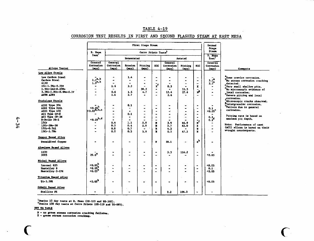
TABLE 4-19 CORROSION TEST RESULTS IN FIRST AND SECOND FLASHED STEAM AT EAST MESA
Alloy8 Teated Lar Alloy Steel. Lw b r b o n Steel Cnrbon Steal 4130 1Cr-1. 3U0-0.25V 1.5Cr-lAl-O.25Uo 3.5Ni-1.8Cr-0.4Uo-0.1V Ml?I A285
Stainlcaa Steel. AIS1 Type 306 AIS1 Type 3161 AIS1 Type 430 MI FJPC CP-8 MI lyp. CP-34 & B r i t s 26-1 l2Cr l 2 c r - l n O - l W 12cr-0. w 15cr-1.m
Copper Based Alloy Deoxidized Copper
bhaipp. Baaed Alloy.
ll00 5005
Nickel m.ad Alloy. Incowl 625 Raatelloy S Enrtelloy C-276
Titanium B u d Allor Ti- 1. SRi
Cobalt Baaed Alloy
S t a l l l t e 16
l i r a t Stage Steam
Cerro Prieto Testa'
General Sorrosion A?B!L
'Omits 15 dny t ea ta a t E. Meaa (GE-119 and NE-302). *Onlit. 150 day t e s t a a t C e r o Prieto ( ~ ~ - 1 1 9 and TO-0~5).
11 - no p o r a r t raaa cotroeion c r a c w i l i lu rae . X - m o a e t r u a corroaim crackin&
KBT TO TABLE
c
Noruerrted
Erosion 0
1.4 - - 3.3
1.6 2.7
0.1 - - 0.1 - - 1.1 0.4 0 , 7 0.5
-
- - - - - - -
General Corroaioa A!!n!L
- - 8.3
13.4 2.6
- - - - - 3.9 2.7 b.3 0.5
20.1
3.3 - - - - -
2.2
Aerated
P i t t ing 0
- - - - 33.5 21.6 -
- - - - - 66.9 63.0
47.3
- 114.2 -
- - - -
106.3
second Stage Steam E. Uesa Teat'
General Corrodon A e L L
- 3.1a 2.5' - - - -
- 0.1
<0.OSc
0.1 -
0.ld - - - - - -
C0.05
C0.05 0.1
e0.05
(0.05
-
Caraantn
crevice corroaion. %o atreaa corrosion cracking
'very mall shallow pita. %o mlcroacopic evidence of elocal corroaion. Severe p i t t ing and local
8Ucroscopic fcorroo.ion. c r a c k obrerved.
Intergranular corroaion. %allure due t o genernl corroaion.
P i t t ing r a t e is baaed on rarfun p i t depth.
Note: Perfomnee of cant (MI) a l l o y is baaed on the i r Wrought counterparts.
detected.
the form of very shallow pits, too small to be measur-d rith an optical micrometer (less than 0.1 mil). ening was noted on coupons of Ti-2Ni and Hastelloy s .
4 J
A general surface rough-
E-Brite 26-1 and Type 430 had excellent resistance to corrosion in the two separated fluid and steam environments but only fair resistance to corrosion ih the wellhead fluid. scopic examination of all Type 430 samples showed the same’shallow pitting that was observed on Type 316 L samples. Only those E-Brite 26-1 samples exposed to the wellhead fluid and to the concentrated fluid from separator #l developed shallow pits. There was no microscopic evidence of corrosion for E-Brite 26-1 samples either in the steam environments or in the concentrated fluid from separator 1’2.
Micro-
Both the 1020 carbon steel and 4130 steel had fair re- sistance to uniform corrosion in the five environments even though the microscopic examination showed general corrosion attack (NE-302).
The corrosion resistance of aluminum 5005 in each of the five environments was poor. I addition t o high general corrosion rates, the aluminum samples were severely pitted and showed a high susceptibility to crevice corrosion (NE-302).
None of the stress-corrosion U-bend samples exposed for 22 days in the steam from separator 81 showed evidence of stress- corrosion cracking.
In near-neutral pH, low-salinity geothermal fluids, 1020 carbon steel and 4130 steel appear to have value as materials of construction. they are low-cost materials.. Aluminum alloys cannot be utilized in geothermal environments due to their low resistance to general,
Their corrosion rates were not excessive and
4-35
pitting, and crevice corrosion in these chloride environments (NE-302).
Table 4-20 presents the preliminary results of tests to determine the effects of temperature and pH on the general lcorrosion of East Mesa wellhead fluid. These results are for Mesa 6-1 fluid at the following conditions:
1. 150°C and pH 5.6-5.8 (normal conditions). 2. 50°C and pH 5.6-5.8 3. 150°C and pH 4.6-4.8.
i The corrosion rates of AISI 1010, AISI 4130, and ASTM A53B decreased with decreasing temperature while AISI 410 and E-Brite 26-1 had low corrosion rates at both temperatures.
The acid injection data confirmed the pH dependence of carbon steel corrosion. Corrosion rates for AISI 1010, AISI 4130, and ASTM A53B increased 3 to 4 times with an acidification of one pH unit. dependence over the range tested (SH-381).
The 410 chromium steel and E-Brite 26-1 showed no pH
4-36
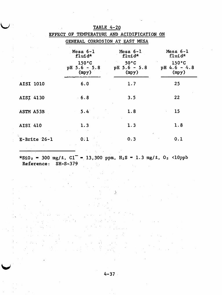
i TABLE 4-20 EFFECT OF TEMPERATURE AND ACIDIFICATION ON
GENERAL CORROSION AT EAST MESA
Mesa 6-1 Mesa 6-1 Mesa 6-1 f l u i d * f l u i d * f l u i d *
150°C 50°C 150°C pH 5 . 6 - 5 . 8 pH 5 . 6 - 5 . 8 pH 4 . 6 - 4 . 8
(mPY 1 (mpY 1 (mPY 1
AISI 1010
AISI 4130
ASTM A53B
AISI 410
E-Brite 26-1
6 . 0 1 . 7 25
6 . 8 3 . 5 22
5 . 4 1 . 8
1 . 3 1 . 3
0 . 1 0 . 3
5 . 4
1 . 3
1 . 8
1 . 3
0 . 1 0 . 3
15
1.8
0 . 1
*Si02 = 300 mg/R, C 1 - = 13,300 ppm, H2S = 1 . 3 mg/R, O2 <10ppb Reference: SH-S-379
,
4-37
4.4 Results of Corrosion Tests at Heber, California KGRA
Limited corrosion testing has been done at the Heber KGRA. The results are summarized in Table 4-21. Their utility is somewhat limited by the fact that scale and corrosion pro- ducts were not removed before weight losses were determined. As a result, corrosion rate calculations based on weight loss are suspect.
4.G.1 Test Conditions
Heat exchanger and in-situ coupon testing were con- ducted at the Heber, California geothermal site (SY-028).
Coupons of potential construction materials were ex- posed to flowing fluid from well Nowlin No. 1 for 42 days. Fluid composition is given in the second column of Table 4-22. After exposure, the coupons were examined and the weight change was determined. However, the coupons were not cleaned or de- scaled which makes accurate general corrosion rates difficult to obtain. carbon steel. about localized corrosion are given in Table 4-23.
No significant weight loss was found except for The observed weight changes and observations
4.4.2 Results
The data in Table 4-23 indicate a uniform corrosion rate of about 2.5 mpy for carbon steel. reasonably well with the uniform corrosion rate of carbon steel at East Mesa of 3.2 mpy. similar. Only Type 316L and $-Brite 26-1 showed signs of local corrosion (small pits). This pitting behavior is similar to results obtained at East Mesa (NE-302).
This value compares
Compositions of these two fluids are
4-38
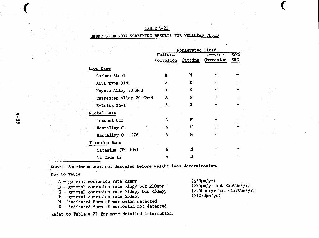
c TABLE 4-21
HEBER CORROSION SCREENING RESULTS FOR WELLHEAD F W I D
I ron Base
Carbon Steel
Nonaerated Fluid Uniform Crevice SCC/
Corrosion P i t t i n g Corrosion SSc
- B N - - AlSl Type 316L A X
Haynrs Alloy 20 Mod A N - - - - Carpenter Alloy 20 Cb-3 A N - - A X E - B r i t e 26-1
Nickel Base
Inconel 625
Hastelloy G
Hastelloy C - 276
Titanium Base
Titanium (Ti 50A)
T i Code 1 2
A N - - A N - - A N
- - A N
A N - -
Note:
Key t o Table
Specimens were not descaled before weight-loss determination.
A - general corrosion rate slmpy B - general corrosion rate .lmpy bu t SlOmpy C - general corrosion rate >lOmpy but t5Ompy D - general corrosion rate 250mpy N - indicated form of corrosion detected X - indicated form of corrosion not detected
( <25w/yr) (>25w/yr but S250w/yr) (>250w/yr but <1270pm/yr) (21270pm/yr)
Refer t o Table 4-22 f o r more de t a i l ed information.
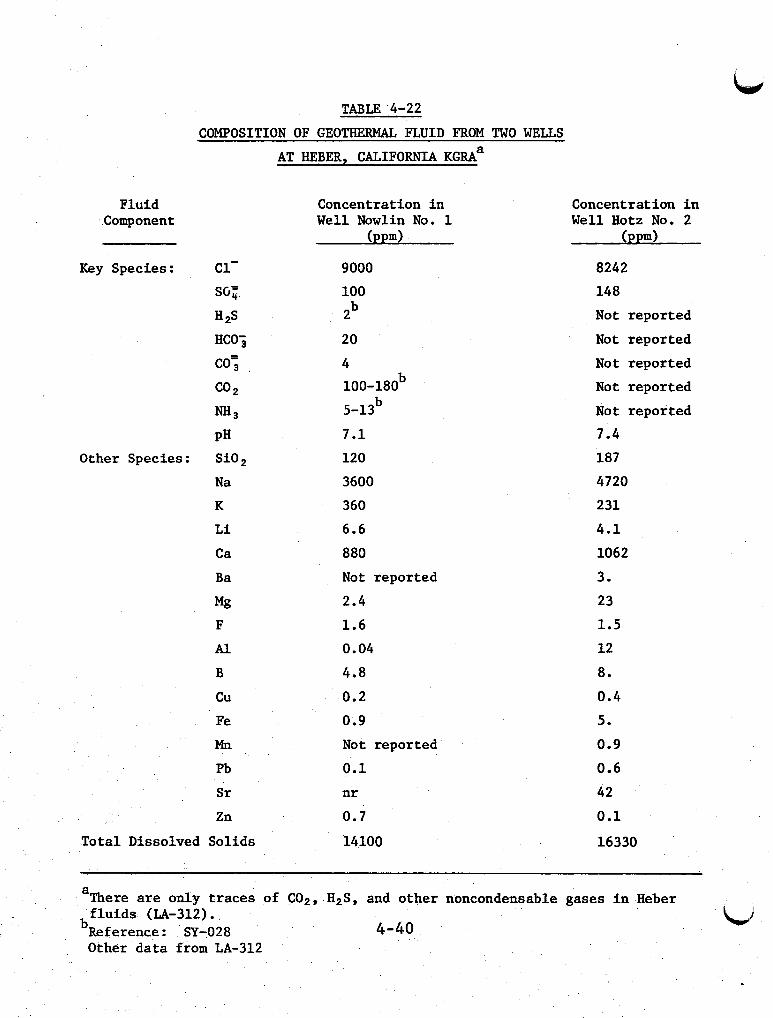
Fluid Component
TABLE '4-22
COMPOSITION OF GEOTHERMAL FLUID FROM TWO WELLS
AT HEBER, CALIFORNIA K G R A ~
Concentration i n W e l l Nowlin No. 1
(PPd
Key Species: c1-
H2S
co; co2 "3
PH
SG;
HCOj
Other Species: SiO,
N a
K
L i
Ca
B a
Mg F
Al B
cu
Fe
Mn
Pb
Sr
Zn
To ta l Dissolved Sol ids
9000 100 pb
20
4 100-180b
b 5-13
7.1
120
3600
360
6.6
880
Not reported
2.4
1.6
0.04
4.8
0.2
0.9 Not reported
0.1 n r
0.7
14100
Concentration i n Well Hotz No. 2
(PPd
8242
148
Not reported
Not reported
Not reported
Not reported
Not reported
7.4
187
4720
231
4.1
1062
3.
23
1.5 12
8.
0.4
5.
0.9
0.6
42
0.1
16330
a
bRef erence : SY-028 4-40
There are only traces of C02, H2S, and o the r noncondensable gases i n Heber f l u i d s (LA-312).
Other d a t a from LA-312
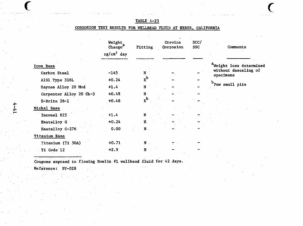
".. . . .... " ^ " - " . . . .. . . ~ - . . ..... ~. ~
TABLE 4-23
CORROSION TEST RESULTS FOR WELLHEAD FLUID AT HEBER, CALIFORNIA
Weighta Change
vg/cm2 day
I ron Base Carbon S t e e l -145
AlSl Type 316L +O. 24
Haynes Alloy 20 Mod +1.4
Carpenter Alloy 20 Cb-3 +O. 48 E - B r i t e 26-1 +0.48
Crevice P i t t i n g Corrosion
SCCI ssc Comments
Nickel Base - - Inconel 625 +1.4 N
Hastelloy G +O .24 N
Hastelloy C-276 0.00 N
Titanium (Ti 50A) +O. 7 1 N
T i Code 12 +2.9 N
- - -
Titanium Base - -
- - Coupons exposed t o flowing Nowlin 111 wellhead f l u i d for 42 days.
Reference: SY-028
- %eight l o s s determined
- without descal ing of
- bFew small p i t s
specimens -
I
Short-term tests of a tube-in-shell heat exchanger were performed at the Heber site by the San Diego Gas and Elec- tric Company. but the following comment was made.
No quantitative corrosion data were available,
"A small-scale, tube-in-shell heat exchanger with four sections in series was tested with geothermal brine from the Nowlin No. 1 well at Heber, Cali- fornia, in the Imperial Valley in late 1974. The brine inlet temperature was approximately 355°F and contained 14,500 ppm dissolved solids.
Three tube materials commonly used in heat ex- changers were tested. These materials were titan- ium, carbon steel, and 90% copper-10% nickel. No corrosion was observed on the titanium tubes after 560 hours of testing. The carbon steel tubes sus- tained slight pitting and decarburization during 560 hours exposure to the geothermal brine. Some corrosion of the copper-nickel tubes was evident after exposure for 200 hours. The copper-nickel tubes corroded at a much more rapid rate than the carbon steel. '* (LO-208)
I
4-42
4.5 Results of Corrosion Tests at Raft River, Idaho KGRA
The summarized "screening" results of corrosion tests at Raft River are shown in Table 4-24. The rates of uniform, pitting and crevice corrosion have been studied in coupon ex- posure tests using wellhead fluid. Another series of tests in- vestigated galvanic and crevice corrosion in potential heat ex- changer materials (MI-305). The results of both test programs are described in the following sections.
4.5.1 Results of Coupon Tests
Field tests at Raft River evalua-ed materials for
Coupons mounted on a test rack with TFE Teflon insula- binary cycle heat exchanger, valves, pumps, and other equipment items. tors and washers were exposed to wellhead fluid from well RRGE 1 at 133°C. Fluid composition is described in Table 4 - 2 5 .
A "planned interval" test procedure was employed in which the duration of coupon exposure was varied up to a maximum of 109 days. whether corrosion rates increase or decrease with time and whe- ther the corrosivity of the fluid changes during the test period.
The results of planned interval tests indicate
After exposure the coupons were visually inspected, cleaned, and weighed. The measured weight losses measured af- ter 109 days of exposure were used to calculate uniform corro- sion rates. cal microscope in order to measure depth of pits and crevices. Pit and crevice depths were measured to the nearest +lpm. mum pit or crevice depths w rates.
Coupons were examined with a monocular metallurgi-
Maxi-
4-43
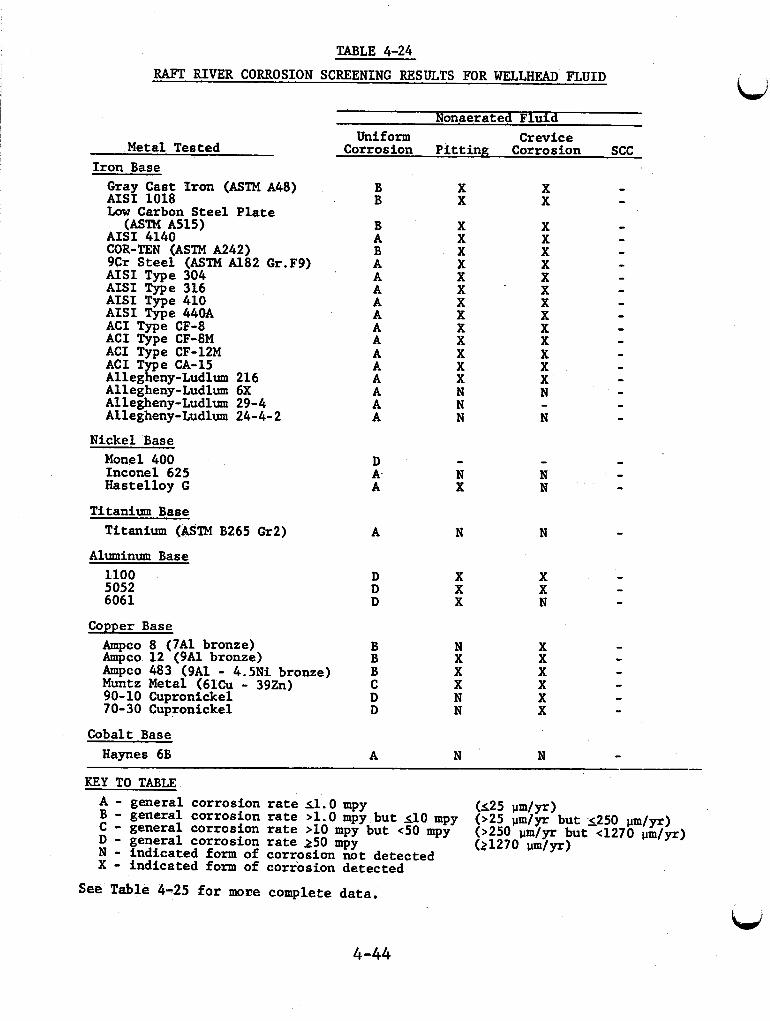
TABLE 4-24 RAFT RIVER CORROSION SCREENING RESULTS FOR WELLHEAD FLUID
I
Non.aerated Fluid
I
I
Metal Tested Iron Base Gray Cast Iron (ASTM A48) AISI 1018 Low Carbon Steel Plate
AISI 4140
9Cr Steel (ASTM A182 Gr.F9) AISI Type 304 AISI Type 316 AISI Type 410 AISI Type 440A ACI Type CF-8 ACI Type CF-8M ACI Type CF-12M ACI Type CA-15 Allegheny-Ludlum 216 Allegheny-Ludlum 6X Allegheny-Ludlum 29-4 Allegheny-Ludlum 24-4- 2
Nickel Base Monel 400 Inconel 625 Hastelloy G
(ASTM A515)
COR-TEN (ASTM A242)
Uniform Crevice Corrosion Pitting Corrosion SCC
B B
B A B A A A A A A A A A A A A A
D A- A
X X
X X X X X X X X X X X X X N N N
X X
Titanium Base Titanium (ASTM B265 Gr2) A N N -
Aluminum Base 1100 5052 6061
D X X - D X X - D X N -
Copper Base Ampco 8 (7A1 bronze) B N X - Ampco 12 (9A1 bronze) B X X - hpco 483 (9A1 - 4.5Ni bronze) B X X - Muntz Metal (61Cu - 39zn) C X X - 90-10 Cupronickel D N X - 70-30 Cupronickel D N X -
Haynes 6B A N N - Cobalt Base
KEY TO TABLE A - general corrosion rate 11.0 mpy I) - general corrosion rate 250 mpy
(125 um/yr)
(21270 um/Yr)
B - general corrosion rate >1.0 mpy but 110 mpy C - general corrosion rate >10 mpy but <50 mpy N - indicated form of corrosion not detected X - indicated form of corrosion detected
(>25 pm/yr but 5250 um/yr) (>250 pm/yr but 4270 um/yr)
See Table 4-25 for moEe complete data.
4-44
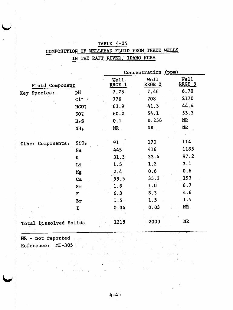
TABLE 4-25 COMPOSITION OF WELLHEAD FLUID FROM THREE WELLS
IN THE RAFT RIVER, IDAHO KGRA
Concentration (ppm)
Fluid Component Key Species: PH
c1-
Other Components: Si02 Na K Li Mi3 Ca Sr F Br I
Well RRGE 1 7.23 776 63.9 60.2 0.1 NR
91 445 31.3 1.5 2.4 53.5 1.6 6.3 1.5 I
0.04
Total Dissolved Solids 1215
Well RRGE 2 7.46 708 41.3 54.1 0.256 NR
170 416 33.4 1.2 0.6 35.3 1.0 8.3 1.5 0.03
' 2000
Well RRGE 3 6.70 2170 44.4 53.3 NR NR
114 1185 97.2 3.1 0.6 193 ,
6.7 4.6 1.5 NR
NR
NR - not reported Reference: MI-305
4-45
The planned interval test procedure showed that corro- sion rates decreased with time. The maximum calculated rates are given in Table 4-26. terials were classified in five categories, based on uniform and local corrosion resistance. Resistance to stress corrosion crack- ing and sulfide stress cracking was not considered. The results are shown in Table 4-27. Class 1 materials have the highest re- sistance to corrosion in Raft River fluid. Materials in Class 2 showed acceptable corrosion resistance. Class 3 materials had moderate corrosion rates, but are still useful as construction materials. Materials in Class 4 had high corrosion rates, and their usefulness is limited to special applications. Class 5 materials showed very little resistance to corrosion and are not useful, especially where crevices occur. Some generalizations about the performance of various steels and alloys in Raft River fluids are given in the following paragraphs (MI-305).
Based on the results in Table 4-26, ma-
4.5.1.1 Cast Iron, Carbon Steels and Low Alloy Steels
The low alloy steels suffered general corrosion as Plain carbon steels and well as pitting and crevice attack.
gray cast iron were pitted worse than the low alloy steels.
4.5.1.2 Stainless Steels
AIS1 Type 410 and 440 steels showed the most catastro- phic attack. to severe pitting in the area of the beveled edge of the TFE washer, as well as the nonoccluded areas. These results lead to the conclusion that these, and similar, alloys should not be used in the hot geothermal fluid under conditions where crevices can be generated. Such applicationp include pump shafts where
The weight loss of these alloys was primarily due
seals and bearings could provide the mechanical condition neces- sary for promotion of crevice corrosion. These alloys are
! 4-46
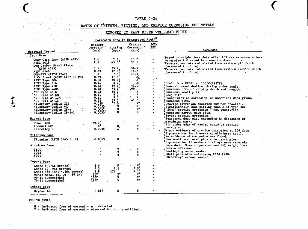
TABLE 4-26 RATES OF UNIFORM, PITTING, AND CREVICE CORROSION FOR METALS
EXPOSED TO RAFT RIVER WELLHEAD J?LUID
Material Tested Iron Base Gray Cast Iron (ASTM A48) AISI 1018 Low Carbon Steel Plate ,
AIS1 4140 COR-TEN (ASTM A242) 9 Cr Steel (ASTM A182 Gr.F9) AISI Type 304 AISI Type 316 AISI Type 410 AISI Type 440A .ACI Type CF-8 ACI Type CF-8M ACI Type CM-12M ACI Type CA-15 Allegheny-Ludlum 216 Allegheny-Ludlum 6X Allegheny-Ludlum 29-4 Allegheny-Ludlum 29-4-2
(ASTM A515)
Nickel Base Monel 400 Inconel 625 Hastelloy G
Titanium Base Titanium (ASTM 8265 Gr.2)
Aluminum Base 1100 5052 6061
Copper Base Ampco 8 (7Al bronze) Ampco 12 (9A1 bronze) Ampco 483 (9A1-4.5Ni bronze) Muntz Metal (61 Cu - 39 Zn) 90-10 Cupronickel 70-30 Cupronickel
Cobalt Base Haynes 68
Corrosion Rate in Nenaerated Fluida Uniform Crevice SCC/
Corrosion' pitting' Corrosion' ssc (mpy) (mpy) (mpy)
1.6 1.8
1.9 0.83 1.1 0.39 0.02 0.11 0.22 0.28 0.02 0.11 0.11 0.22 0.038 0.0035 0.0037 0.0035
79.P NP
0.0035
0.0063
s S s
3.9 7.5 9.8
20y 27 5p 164p
0.017
7.9 13.2 43. Sb 33.6
33.1 36.9 32.9' 14.7 7. Sd 13.2 17. 4. Xf 30. 3s Xh 8.7' xj 39. 5k 41. O1 76.Sm 100 30.3 X 8.7 X 8.7 X 39.5 41.0 47.9 X"
N N
N N N X0
N N X' N
N N
X X X X X N
N N
Comment s ---- -
'Based on weighL loss data after 109 day exposure unless
*Penetration rate calculated from maximum pit depth
'Penetration rate calculated from maximum crevice depth
otherwise indicated in comment column.
(measured to fl um).
(measured to 21 urn).
"Fluid from RRGEl at 133'C(272'F) :General broad shallow pitting under scale. ,,Numerous pits of varying depth and breadth. .Numerous small pits. fDeep pits.
:Numerous pits. iCrevice corrosion observed but not quantified. j$ignificantly less pitting than AISI Type 304.
:Numerous narrow deep pits. ,Severe crevice corrosion.
"machining marks.
'Minor evidence of crevice corrosion at 109 days. 'Exposure was for 2 weeks (preliminary test). :No evidence of corrosion was found.
SExposure for 11 weeks all alloys were severely
,Severe erosion.
:Small pits with dealloying into pits.
"I)eep"crevice corrosion- no numerical data given.
Some" crevice corrosion - not quantified. Scattered deep pits extending in direction of
Pit under edge of washer could be crevice corrosion.
Few small scattered pits - no depth given. corroded. Some coupons showed 25% weight loss.
Dealloying under washer.
"Grooving" around washer.
KEY TO TABLE
N - indicated form of corrosion not detected. X - tndicated form of corrosion observed but not quantified.
c
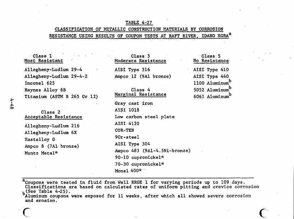
. ~ ~ . . . .. . . ~~ -. . . - -- - - .. - . . i . ~ . . . , .~~ . .~ .”. . . ~ .... . -. - -I . - - - . . - . .... ~
TABLE 4-27 CLASSIFICATION OF METALLIC CONSTRUCTION MATERIALS BY CORROSION
RESISTANCE USING RESULTS OF COUPON TESTS AT RAFT RIVER, IDAHO K G R A ~
Class 1 Class 3 Class 5 Most .Resist,ant Moderate Resistance No,Resistance
Allegheny-Ludlum 29-4 Allegheny-Ludlum 29d4-2 Inconel 625 Haynes Alloy 6B Titanium (ASTM B 265 Gr
P I P 03
Class 2 Acceptable Resistance
Allegheny-Ludlum 216 Allegheny-Ludlum 6X Hastelloy G Ampco 8 (7A1 bronze) Muntz Metal*
AISI Type 316 AISI Type 410 Ampco 12 (9A1 bronze) AISI Type 440
1100 Aluminum b
Class 4 Marginal Resistance
Gray cast iron AISI 1018 Low carbon steel plate AISI 4130 COR-TEN 9Cr - s tee1 AISI Type 304 Ampco 483 (9A1-4.5Ni-bronze) 90-10 cupronickel*
5052 Aluminumb b 6061 Aluminum
70-30 cupronickel* Monel 400*
Coupons were tested in fluid from Well RRGE 1 for varying periods up to 109 days. a Classifications are based on calculated rates of uniform pitting and crevice corrosion (See Table 4-25).
bAluminurn coupons were exposed for 11 weeks, after which all showed severe corrosion and erosion.
c c
,
i
martensitic and other high chromium martensitic stainless steels have shown great susceptibility to sulfide stress cracking.
Two austenitic stainless steels were tested. The pitting and crevice corrosion of AISI Type 304 were similar to the attack on AISI Types 410 and 440, though the pits were not as numerous or deep. Though localized attack was severe, this material may be usable in some applications. also pitted, but to a much lesser extent than Type 304. basis of these data, Type 316 would be acceptable in many appli- cations. sion cracking in dilute chloride solutions.
AISI Type 316 was On the
Both of these alloys are susceptible to stress corro-
Precipitation-hardening stainless steels such as 17-4PH are modifications of the austenitic stainless steels. In these alloys the nickel content is lower and elements such as aluminum, copper, molybdenum and niobium are added to generate the second phase that results in hardening. AISI 304 stainless steel in regard to corrosion resistance in most environments. stern applications, its use in the Raft River geothermal fluid should be preceded by careful testing and evaluation.
I
These materials are similar to
Because the 17-4PH material is used in valve
1
i
I
The super stainless steels, Allegheny-Ludluzn Alloys 216 (20Cr-24Ni-2.5Mo), 6X (20Cr-24Ni-6Mo), 29-4 (29Cr-4Mo), -and 29-4-2 (29Cr-4Mo-2Ni) were resistant to general and local corro- sion. The alloy 216 did show some pitting near the TFE washer.
The stress corrosion cracking resistance of these Nickel-free 29-4 is 'more resistant, though all
1
I I
alloys is high. will resist cracking in boiling 20% NaCl (GE-119).
u 4-49
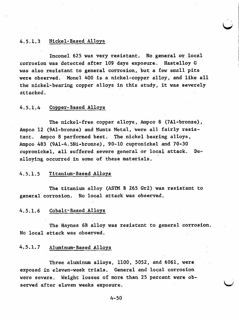
4.5.1.3 Nickel- Based Alloys
Inconel 625 was very resistant. No general or local corrosion was detected after 109 days exposure. was also resistant to general corrosion, but a few small pits were observed. the nickel-bearing copper alloys in this study, it was severely attacked .
Hastelloy G
Monel 400 is a nickel-copper alloy, and like all
4.5.1.4 Copper-Based Alloys
The nickel-free copper alloys, Ampco 8 (7Al-bronze), Ampco 12 (9Al-bronze) and Muntz Metal, were all fairly resis- tant. Ampco 8 performed best. The nickel bearing alloys, Ampco 483 (9Al-4.5Ni-bronze), 90-10 cupronickel and 70-30 cupronickel, all suffered severe general or local attack. De- alloying occurred in some of these materials.
4.5.1.5 Titanium-Based Alloys
The titanium alloy (ASTM B 265 Gr2) was resistant to general corrosion. No local attack was observed.
4.5.1.6 Cobalt-Based Alloys
The Haynes 6B alloy was resistant to general corrosion. No local attack was observed.
4.5.1.7 Aluminum-Based Alloys
Three aluminum alloys, 1100, 5052, and 6061, were General and local corrosion exposed in eleven-week trials.
were severe. served after eleven weeks exposure.
Weight losses of more than 25 percent were ob-
4-50
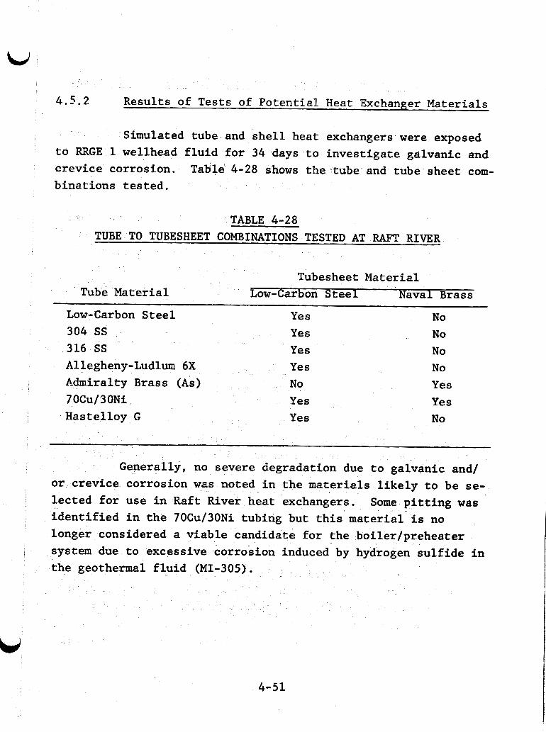
4.5.2 Results of Tests of Potential Heat Exchanger Materials
Simulated tube and shell heat exchangers were exposed to RRGE 1 wellhead fluid for 34 days to investigate galvanic and crevice corrosion. Table 4-28 shows the tube and tube sheet com- binations tested.
TABLE 4-28 TUBE TO TUBESHEET COMBINATIONS TESTED AT RAFT RIVER
Tubesheet Material Tube Material Low-Carbon Steel Naval Brass
Low-Carbon Steel Yes No 304 SS Yes No 316 SS Yes No Allegheny-Ludlum 6X Yes No Admiralty Brass (As) No Yes 7 OCu/ 3 ON i Yes Yes Hastelloy G Yes No
Generally, no severe degradation due to galvanic and/
Some pitting was or crevice corrosion was noted in the materials likely to be se-
lected for use in Raft River heat exchangers. identified in the 70Cu/30Ni tubing but this material is no longer considered a viable candidate for the boiler/preheater system due to excessive corrosion induced by hydrogen sulfide in the geothermal fluid (MI-305).
4-51
4.6 Results of Corrosion Tests in Salton Sea, California,
The geothermal resource at Salton Sea, California has been the subject of extensive laboratory and field testing. results are summarized in "screening" format in Tables 4-29 through 4-36. Laboratory results are given in parentheses.
The
The following sections provide details about the test Gen- conditions and give numerical values for corrosion rates.
eralizations about performance and applicability of various steels and alloys are presented. sented in Section 4i5.1. Results of field tests follow in Sec-
Laboratory results are pre-
tion 4 . 5 . 2 .
4.6.1 Results of Laboratory Tests Using Synthetic Fluids
Two types of laboratory tests using synthetic fluids have been conducted (NE-302). One series of tests was done in a high pressure autoclave at 232°C. at atmospheric pressure at 105°C. Both series of tests used a solution made in the laboratory by dissolving metal chlorides, silicates, and metaborates in water and adjusting the pH with sodium hydroxide. The composition of the test solution is based on that of flashed fluid frdm well IID 2.
The second series was done
The composition is defined in Table 4-37.
4.6.1.1 Results of Autoclave Tests at 232°C
Twenty-three commercially available alloys were tested in the autoclave tests. Coupons, U-bend stress corrosion speci- ments, butt-welded samples, and specimens with fabricated crev- ices were exposed to 1300 ml of unstirred synthetic fluid con- tained in a two-liter, high pressure glasslined stainless steel Lid
4-52
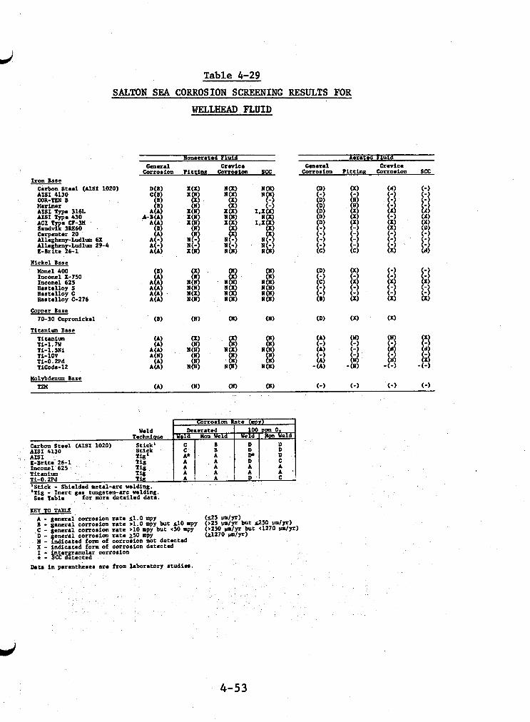
Table 4-29
SALTON SEA CORROSION SCREENING RESULTS FOR
WELLHEAD FLUID
Aarated Fluid General crevice
Corroeion Pi t t inn Corroiion SCC Iron Base
Carbon Steel (AIS1 1020) AIS1 4130 COR-TEN B Uariner AISI Type 3161. AISI Type 430 ACI e Q-3M S a n d 2 3M60 - c a r p m t a 20 Allegheny-Ludltlm 6X All. heny-Ludlm 29-4 I-llrfte 26-1
Nickel Base llonel 400 Inconel X-750 Inconel 625 b i t a l l o y S Haatellog C IIaatalloy 0276
Copper Base 70-30 Cupronickel
Ti tan im Base Titaniuu Ti-1.7U Ti-1.5Ni Ti-1OV Ti-0.2Pd Ticode-12
Molybdenum Base Tm
AISI 4130
'Stick - Shielded metal-arc welding. 'Tig - Iner t gas rungaten-arc welding. for more detailed data. See Tabla
r a t e s1.0 mpy r a t e >1.0 mpy but d 0 mpp r a t e >10 mpy but ~ 5 0 mpy r a t e 250 mpy corroaion not detected corroaion detected
KEY TO TABLE A - &enera1 CorroSion B - general corroaion
.C - general corroaion eneral corroaion Kf ndicated form of
X - indicated form of ntergranular corroaion f : 9 CC detected
Data i n parmtheae. are from laboratory itudiea.
4-53
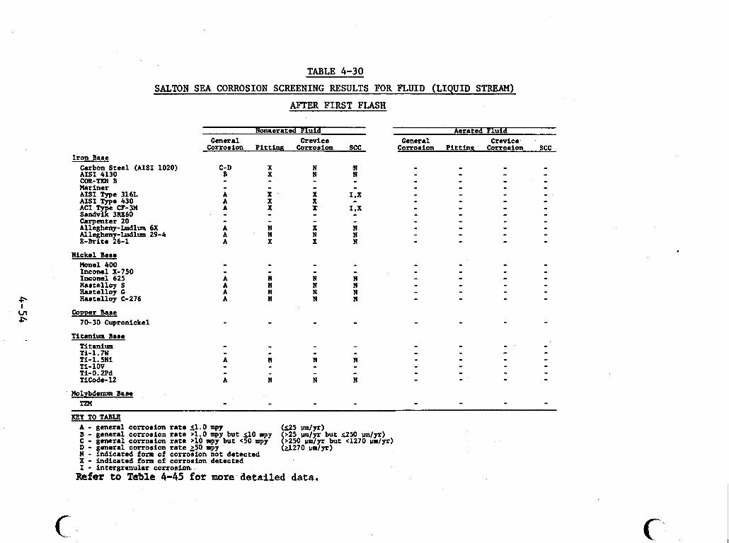
Iron Base
.............. . . . . . . . . . . . . . . . . . . . .................................. ........... . . . . . . . . . . . .- ~ - - . .
TABLE 4-30
SALTON SEA CORROSION SCREENING RESULTS FOR FLUID (LIQUID STREAM)
AFTER F I R S T FLASH
Carbon Steel (AISI 1020) AISI 4130 COR-TEN B Mariner AISI Type 316L AIS1 Tvue 430 ACI - k CF-3W Sand% 3RE60 Carpenter 20 Allegheny-Ludlum 6X Allegheny-Mlum 29-4 E-Brite 26-1
Nickel Base M e 1 400 Inconel X-750 Inconel 625 Hastelloy S h s t e l l o y C
-Aantelloy C-276
Comer Bane 70-30 Cupronickel
Titanium Bane Titanium Ti-1.7W Ti- 1.511 Ti-1OV Ti-0.2Pd TiCode-12
Holybdenum Base TM
Nonaerated Fluid General Crevice
Corromion Pi t t ing Corrosion SCC
Aerated Fluid General Crevice
Corrorion P i t t ing Corrosion SCC
KEY TO TABLE
B - general corrosion rate >1.0 mpy but 110 mpy C - general corroaion rate >10 mpy but <50 mpy
A - general corrosion rate (1.0 mpy
D - general corrosion r a t e >50 mpy N - indicated form of corroTion not detected X - Indicated form of corronion detected I - intergranular corrorirm
(a270 Wyr)
Refer to Table 4-45 for more detailed data.
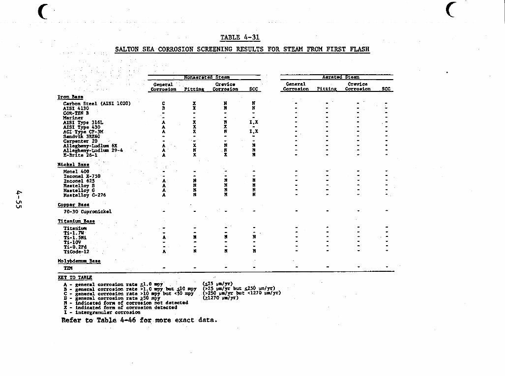
. . . . ...~ ~. , . , , , . . . _ _ ..I .._...I._ ".I._ .... . . .. .. ~.. ~ . " . , . , . - . - . . . ~. - _ . . . .- .
TABLE 4-31
* I
. c n cn
SALMN SEA CORROSION SCREENING RESULTS FOR STEAM FROM FIRST FLASH
Iron Base Carbon Steel (AIS1 1020) AISI 4130 COR-TEN B Mariner AISI Type 316L AISI Type 430
SmdvE 3RE60 Carpenter 20 . Allegheny-Ludlum 6X Alleghen Ludlm 29-4 E-Brim 1&1
ACI T CF-3M
N i c k e l Base Hone1 400 Inconel X-750 Inconel 625 Bastelloy S Hastelloy G Hastelloy C-276
Copper Base 70-30 Cupronickel
Titanium Base Titantus Ti-1.m Ti- 1.5191 Ti-1W Ti-O.2Pd TiCode- 12
Molybdenum Base T a l
Nomerated Steam Aerated Steam
Corrosion Pi t t ing Corrosion SCC Corrosion PittinR Corrosion SCC General Crevice General Crevice
C B - - A A A
A A A
- -
X X
X X X
X N X
- - - -
KEY TO TABU A - general corrosion r a t e 51.0 mpy (125 U d F ) B - general corrosion r a t e >1.0 mpy but 3 0 mpy C - general corrosion r a t e >10 apy but 4 0 mpy D - general corrosion r a t e 250 mpy N - indicated form of corrosion not detected X - indicated form of corrosion detected I - intergranular corrosion
0 2 5 m / ~ but 1250 d p r )
L 2 7 0 um/yr) >250 u d y r but 4270 um/pr)
Refer t o Table 4-46 f o r more exact data.
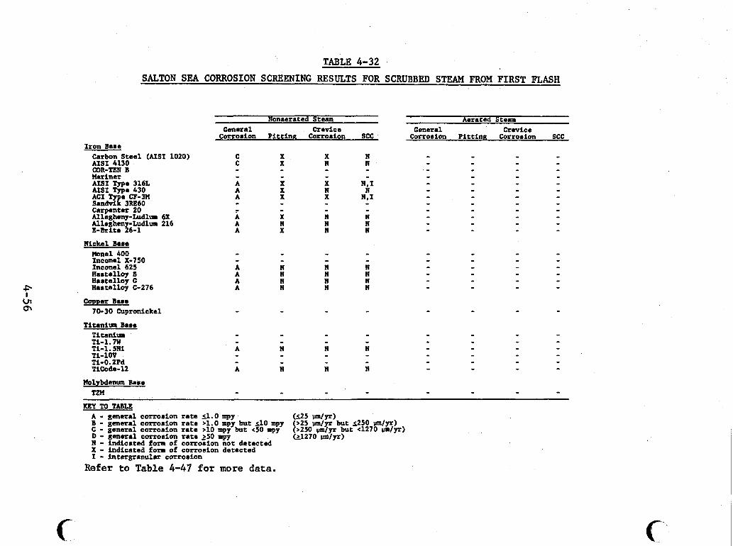
. .. . . . . , . _~ . ._. . . . . , . ~. " " . . . . - . - . .. . ... . . . . "... .___. ~
TABLE 4-32 SALTON, SEA CORROSION SCREENING RESULTS FOR SCRUBBED STEAM FROM FIRST FLASH
Nonaerated Stem Aerated Stem
Corrosion Pitting Corrosion SCC Corrosion PittinR Corrorion SCC Crevice General General Crevice
Iron B M ~ Carbon Steel (AISI 1020) AISI 4130
Mariner AISI Type 316L AISI Type 430
e CF-3U 3RE60
Carpenter 20 Allegheny-Ludlum 6X Alleghm -Ludlum 216 E-Brite $6-1
COR-TEN B
Nickel Bare Moonel 400 Inconel X-750 Inconel 625 Hartellay S Hastelloy G Hastellay C-276
70-30 Cupronickel Copper Base
Ntanita Emre Titanium Ti-1.m Ti-1 .5N1 Ti-1W Ti-0.2Pd TiCoda-12
Molybdenum Base TZM
c
C C
A A A
-
- - A A A
X X X N
X X X N X X
X N N N X N
- - - - - - - -
- - - - - - - - A N N N A N N N A N N N A N N N
I[gP TO TABLE A - general corrosion rate S1.0 mpy B - general cortosion rate >1.0 mpy but 510 mpy C - general corrosion rate >10 mpy but e50 mpy D - general cortosion rate 250 mpy N - indicated form of corrosion not detected X - indicated form of corroaion detected I - intergranular corrosion
(125 W / P ) >25 u m / p but 1250 um/Yr) [>250 d p t but 4270 u m / v ) (11270 u d p )
Refer to T a b l e 4-47 for more data.
C'
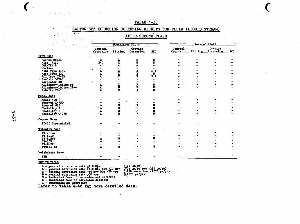
. . . .. ..
c TABLE 4-33
SALTON SEA CORROSION SCREENING RESULTS FOR FLUID (LIQUID STREAM) AFTER SECOND FLASH
Aerated Fluid Nonaerated Fluid General Crwice General Crevice
Corrosion Pittint? Corrosion SCC Corrosion Pi t t ing Corrosion SCC
N N
I ron Bane C
B-C - - A A A
A A A
- -
Carbon Steel AIS1 4130
Mariner AISI Type 316L AISI Type 430
e CP-3U gtk% 3RE60 carpenter 20 Alleghmy-Ludlm 6X
.Alleghmy-Ludlm 29-4 E - B r i t s 26-1
COR-TEN B
N . 1 N
N . 1
X X X
X X X - -
N N N
X N X
Hans1 Baee Hone1 400 Inconel X-790 Inconel 625 Aastellap S Hastellby G Rastellap C-276
70-30 Cupronickel m e r Bast
- - A A A A
- N
11 N
n
Titani tn Base
TI-iov Ti- 0.2Pd TiCode-12
wy To TABLE
- ~ _______. ~ ~
H - indicated fonn of c o r r o h n bbt detected X - Indicated form of corrosion detected
-
I - intergranular corrosion R e f e r t o T a b l e 4-48 for more detailed data.
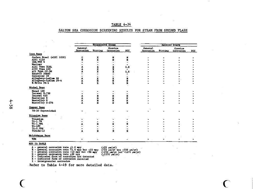
SALTON SEA CORROSION SCREENING RESULTS FOR STEM FROM SECOND FLASH
Nonaerated Steam Aerated Steam
Corrosion Pitting Corrorion SCC Corrosion PittlnK Corrosion SCC General Crevice General Crevice
Iron Base Carbon Steel (AIS1 1020) C X N N - - - - AISI 4130 B X N N - - - - COR-TEN B - - - - - - - - Mariner AISI Type 316L AISI Type 430
e CF-3M 3RE60
Camenter 20 Alligheny-Ludlum 6X Alleghen Ludlum 29-4 E-Brite {'a-1
Nickel Bare Mona1 400 Inconel X-750 Inconel 625 Hartelloy S Bastelloy G Hastelloy C-276
70-30 Cupronickel Copper B u e
A A A
X N X
X N X
N N N
- - A A A A
- N N N N
N N N
Titanirrm Base Titanlm Ti-1.7W Ti- 1.581 Pi-1ov Ti-0.2Pd TiCodc-12
Molybdenum Base T1W
KEY TO TABU A - general corrorion rate 4.0 mpp B - general corrosion rate 71.0 mpy but e10 mpy C - general corrosion rate >10 mpy but G O mpy D - general corrosion rate 250 mpy N - indicated form of corrosion not detected X - indicated form of corrosion detected I - intergranular corrosion
( 2 5 d y r ) (>25 umlyr but 4250 vmlyr) (>250 vmlyr but-cl270 umlyr) (21270 umlyr)
Refer to Table 4-49 for more d e t a i l e d data.
c
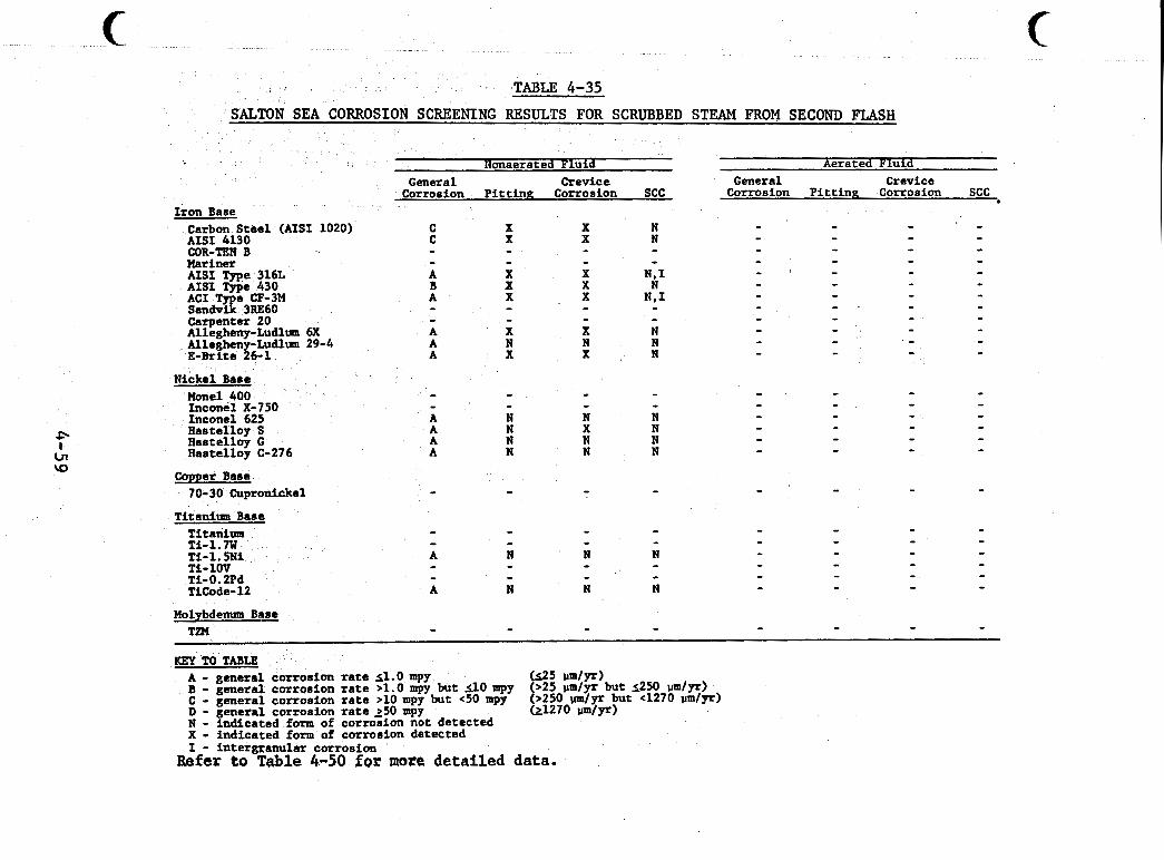
TABLE 4-35
SALTON SEA CORROSION SCREENING RESULTS FOR SCRUBBED STEAM FROM SECOND FLASH
Aerated Fluid
Corrosion P i t t i n g Corrosion SCC General Crevice
Honaerated Fluid General Crevice
Corrosion P i t t i n g Corrosion SCC I ron Base
Carbon S t e e l (US1 1020) AISI 4130 COR-TEN B Mariner A I S I Type 316L AISI Type 430
e CF-3M $Ed% 3Re60 Cazpenter 20 Allegheny-Ludlm bx Allegheny-Ludlm 29-4 E - B r l t e 26-1
Nickel Base
C C - - A B A - - A A A
N N N
- - A A A A
Monel 400 Inconel X-750 Inconel 625 Hastelloy s Hastelloy G Has t e l l o y C- 27 6
70-30 Cupronickel Copper Base
- N N N N
CI I cn \o
T i t a d - Base Titanium TI-1.m Ti- 1.5Ni Ti-1OV Ti- 0.2Pd TiCode-12
Molybdenum Base TZM
KEY TO TABLE A - general corrosion r a t e s l . 0 mpy (125 Irm/p) B - general corrosion r a t e >1.0 mpy but 110 mpy (>25 v m / p but 5250 IJm/p) C - general corrosion r a t e >10 mpy but (50 mpy ( ~ 2 5 0 W / p but 4 2 7 0 v m / p ) D - general corrosion r a t e 250 mpy W 2 7 0 Irmm/pZ) N - ind ica ted form of corrosion not detected X - Indicated form of corrosion detected I - in te rgranular corrosion
Refer to Table 4-50 for more, detailed data.
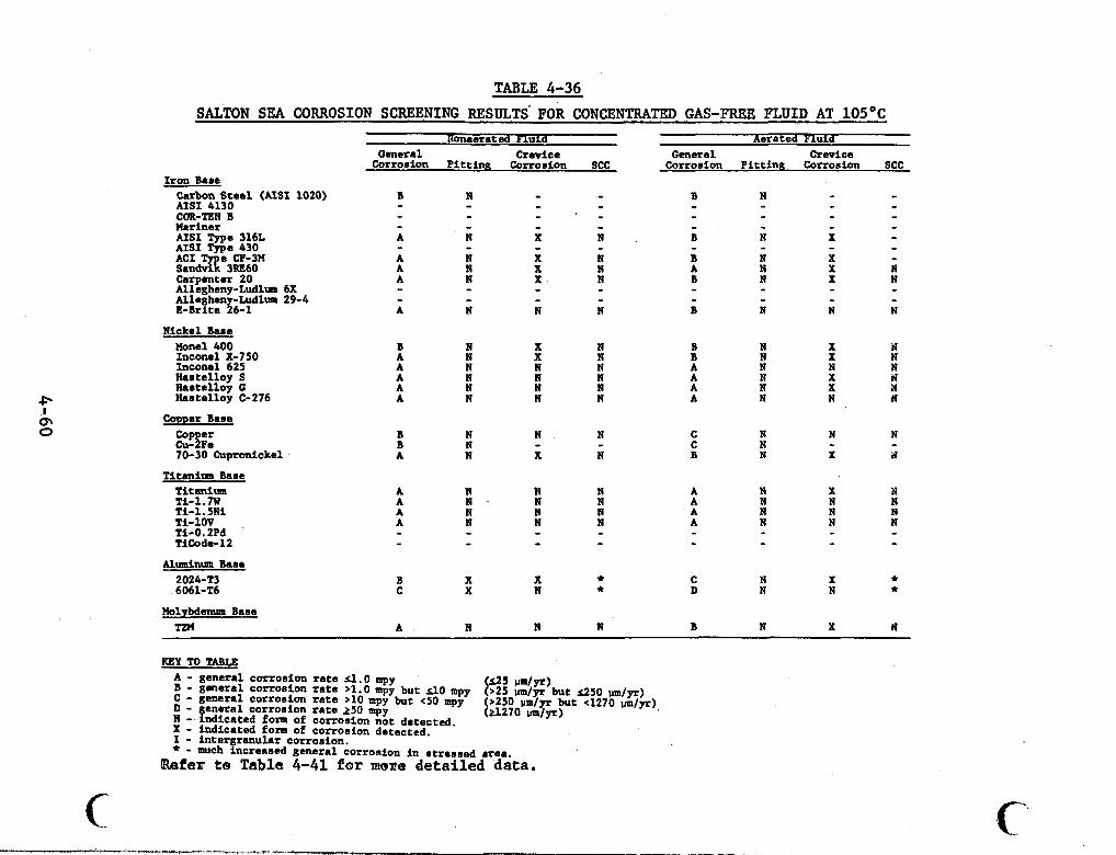
TABLE 4-36
SALTON SEA CORROSION SCREENING RESULTS' FOR CONCENTRATED GAS-FREE FLUID AT 105OC
P I
Q\ 0
Iron Bare Carbon Steel (AIS1 1020) AISI 4130 COR-TEN B Mariner AISI Type 316L AISI Type 430
e CF-3H 3RE60
Carpenter 20 Allegheny-Mlum 6X Alleghen -Ludlum 29-4 E - B r i t e %6-1
Nickel Bare Wonel 400 Inconel X-750 Inconel 625 Hartelloy S Hartelloy G Hartelloy C-276
Comer Bare
2%: 70-30 Cupronickel
T l t w l m Base Titanium Ti-1.7W Ti- 1.5NI Ti-1OV Ti-0.2Pd TlCodc 12
A l d u m Bare 2024-T3 6061-T6
Molybdenum Bare T1M
U l d Nomerated Fl
Corroeion P l t t i m Corrorion SCC General Crevice
B N X N A N X N A N N N A N N N A N N N A A N N
B N N N B N - A N X N
A B N N A N - N N A N N N A N N N - - - -
B X X * C X N *
A N N N
Aerated Fluid General Crwice
Corrosion Pi t t ing Corrosion SCC
B N X N B N X N A N N N A N X d A N X N A N N N
C N ti N C N B N X a
- -
A N X N A N N N A N N N A N N N
C N X * D N N *
B N X N
KEY TO TABLE A - general currorion r a t e r 1 . 0 mpy B - general corrosion r a t e >1.0 mpy but s10 mpy t% $$s)but s.250 p m / v ) C - general c o r r o r i a r a t e > I O apy but <50 mpy D - general corrosion rate 250 mpy N - indicated form of corrosion not detected. X - indicated form of corrosion detected. I - intergranular corrosion. * - much increaeed general corrosion i n rtressed area.
(>250 pm/yr but e1270 pmfyr) (A270 umlyr)
bfer to, Table 4-41 for maze detailed data.
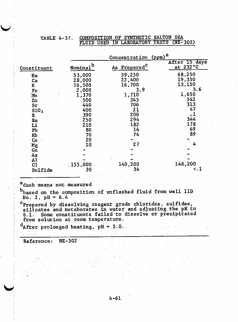
TABLE 4-37. COMPOSITION OF SYNTHETIC SALTON SEA F L U I D USED I N LABORATORY TESTS (NE-302)
a Concentration (pp m) A f t e r 15 days
Constituent Nominal b A s Prepared' a t 232°C
N a Ca K Fe Mn Zn Sr si0 2
B Ba L i Pb Rb cs *
Mg G e A s A 1 c1 Sulf ide
53,000 28,000 16 , 500 2 , 000 1 , 370
500 440 400 390 250 2 10
80 70 20 10 -
- - 155,000
30
59,250 22 , 400 16,700
1,710 345 706 21
200 294 182 14 74
27
3.9
- - -
140,200 34
68,250 19,350 13,150
1,650 542 313 47 -1
344 178 69 89
4
3.6
- - - -
148,200 <. 1
adash means not measured bbased on the composition of unflashed f l u i d from w e l l 1 1 D
'Prepared by dissolving reagent grade chlorides , su l f ides , No. 2 , pH = 6.4
si l icates and metaborates i n water and adjust ing t h e pH t o 6.1. Some const i tuents f a i l e d t o dissolve o r prec ip i ta ted from solut ion a t room temperature.
d A f t e r prolonged heat ing, pH = 5.0.
Reference: NE-302
4-61
c autoclave. The coupons and crevice specimens were suspended in the solution with glass supports while the U-bend specimens rested on the bottom of the autoclave. Alloys were tested in separate exposures for periods of 15 to 30 days.
Tests specimens were immersed in the test solution, the
The vapor pressure over the solution at these solution was vacuum degassed, and the autoclave was sealed and heated to 232+2"C. conditions was about 360 psig. In some tests another gas was injected into the autoclave from a cylinder. Either oxygen, C02 or methane was added until the pressure in the autoclave reached a specified value. The pressures of added gases were calculated based on Henry's Law Constants so that a specific concentration of the gas would be dissolved in the solution at the test conditions. Tests were done with no added gases, with 100 ppm O2 in the li- quid, 250 ppm C O P , and 100 ppm CH4.
After exposure the specimens were cleaned and examined microscopically. weight loss for both coupons and U-bend specimens. Pitting and crevice corrosion rates were calculated based on optical measure- ments of pit or crevice depth.
Uniform corrosion rates were determined by
Weld-related corrosion failures were studied in de- aerated and oxygenated fluid at 232°C. Weight-loss samples were butt-welded together following practices recommended by the Ameri- can Society for Metals. These samples were not heat treated to relieve stresses prior to corrosion testing.
Thenumerical corrosion rates measured in autoclave tests are summarized in Tables 4-38, 4-39, and 4-40. Table 4-38 shows results of tests of coupons, crevice specimens, and U-bend specimens in deaerated fluid and tests in which oxygen was added
LiJ 4-62
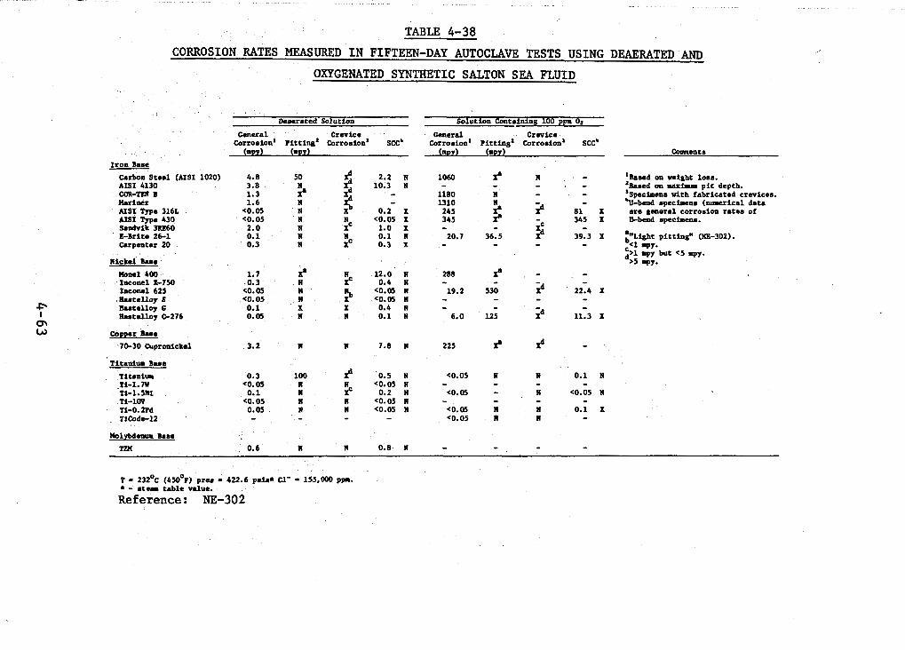
TABLE 4-38 CORROSION RATES MEASURED IN FIFTEEN-DAY AUTOCLAVE TESTS USING DEAERATED AND ,
OXYGENATED SYNTHETIC SALTON SEA FLUID
I roa Base Carbon Stee l (AIS1 1020) 4.8 50 AISI 4130 3.8 COR-m B 1.3 Huiaer 1.6 N AISI Type 3161 <O. 05 N AISI Type 430 <O. 05 N Sadvik 3lU60 2.0 N E-Brite 26-1 0.1 N Carpenter 20 0.3 N
i 2.2 N
N (0.05 X
N 0.1 N Xc 0.3 X
XC 1.0 x
n i c k 1 b e m a e l 400 1.7 i IaC0nclX-750 0.3 N IUCOM~ 625 (0.05 N Rastelloy S <O. 05 II Raatslloy C 0.1 X Hnstelloy 0 2 7 6 0.05 N
70-30 Cupronickel 3.2 N Copper B n e
N 12.0 N Xc 0.4 N
CO.05 N 3 '0.05 N X 0.4 N n 0.1 N
N 7.8 N
Dcacrated Solution
Corroaioa' pitting' Corrosion' SCC' General Crevice
(WY) (rpY)
T i t a d - I)ub
T i U d U TI-1.m
Ti-109 Ti-O.2Pd TiCodcl2
~ i - i . 5 ~ 1
0.3 100 <O. 05 n
0.1 n c0.05 N
0.05 N
Ilolybdwcom Base
fl 0.5 N <0.05 N 2 0.2 N
N <0.05 N N <0.05 N - -
T M 0.6 N N 0.8 N
1060 i 1180 n - -
1310 245 345 3 -
20.7 36.5 - -
288 f - 19.2 530
- 6.0 125
225 i
- <0.05 N C0.05 N
Solution Coat.iniag 100 ppm 02
General Crwico corrosion' ~ i t t i a g ' ~ o r r o s i o a ~ SCC'
( m m ) ( m ! ?
81 x 345 x - 39.3 x - - -
22.4 X - - 11.3 X
0.1 N
C0.05 N
0.1 x
- - -
Cormenta
'Baaed oa w i g h t loss. 'Based on UU~JMIE p i t depth. 'Spechean with fabricated crevices. %-bend mpcetclls (mnerical data are gmera l corrosion ra tes of U-bead specimens.
:Light pitting" (NE-302). c<l d>l =PY. mpy but e 5 q y .
.5 -9.
__
T - 232OC (450°F) pres - 422.6 psi.* C1- - 1%m PP.. * - stea table value.
Reference: NE-302
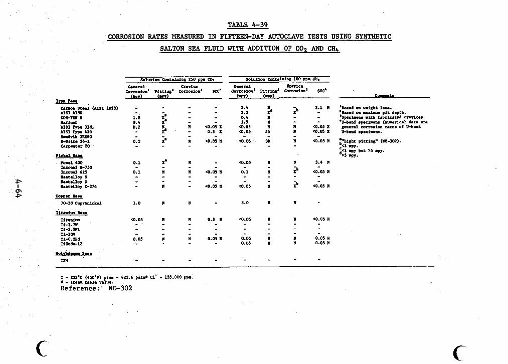
TABLE 4-39 CORROSION RATES MEASURED IN FIFTEEN-DAY AUTOCLAVE TESTS USING SYNTHETIC
SALTON SEA FLUID WITH ADDITION OF cor, AND CHI,
Iron B e n Carban S t n l (AIS1 1020) A M Y 4130 COR-TUN 1 Herim AISI Type 31& AISI Type 430 S.ndrik 3RJI66 B-Britm 26-1 Carpentar 20
M i C k d b.M
?Ionel 400 hc-1 X-750 I n c d 625 b e t a l l o y s 8astalloy 0 b e t a l l o y 5 2 7 6
Comer Bema 70-30 copronickel
tltmica Beme Tit&- Ti-1.7W Ti-1. W i Ti-105' Ti-0. ZPd TiCode-12
1.0 II I -
2.4 A
0.4 A
(0.05 II <0.05 55
.<0.05: 30
3.3 Xa
1.5 n
- - -
2.1 1 - - - <0.05 x (0.05 X
(0.05 1 -
3.0 n N
' m e d 011 weight lo... ' h e d on rarCmr p i t depth. '~pmcime~ with fabricated crevice.. 'U-bead apecimeaa ( n m r i u l data are .general com8ion rate. of U-bend U-bend . p @ e i w ~ .
3 i g h t pitting" (m-302). c<l (1 .PI. mpy but >5 mpy.
% .PI.
<O .05 1 - - - - - - 0.05 II 0.05 n
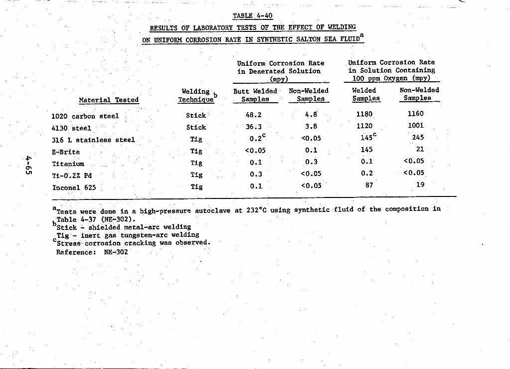
TABLE 4-40
RESULTS OF LABORATORY TESTS OF THE EFFECT OF WELDING
ON UNIFORM CORROSION RATE IN SYNTHETIC SALTON SEA FLUID^
to the autoclave. Table 4-39 shows results obtained when COn and CHI, were added. Results of tests of welded and non-welded speci- mens are given in Table 4-40. Results are shown for both deaerated fluid and oxygen addition. findings for carbon steels, stainless steels, and nickel, titanium, copper, and molybdenum alloys.
The following paragraphs summarize the
In deaerated fluid, the uniform corrosion rates of car- bon and low alloy steels were less than 5 mpy. Carbon steel (AISI 1020) developed deep pits while the other alloys were resistant or suffered only slight attack. severe. Only AISI 1020 and 4130 were tested for stress corrosion cracking. 4130 U-bend specimen was three times the weight loss of the AISI 4130 coupon. welding increased the uniform corrosion rate tenfold in the de- aerated fluid.
The crevice corrosion rates were
Both were resistant, but the weight loss of the AISI
In the case of 1020 carbon steel and 4130 steel,
The addition of oxygen increased general corrosion of low alloy steels Q1000-fold. There were no differences in weight loss for the welded and non-welded samples of 1020 and 4130 steel in tests when oxygen was added.
Stainless Steels
In non-aerated fluid stainless steels had general corro- sion rates of less than 2 mpy. moderate crevice corrosion though no pitting was observed. E-Brite 26-1 was resistant to stress corrosion cracking. caused a slight increase in weight loss, and stress corrosion cracking was noted in welded specimens of the 316 L.
Some were subject to slight or Only
Welding
Addition of oxygen caused severe increases in general Intergranular corrosion corrosion, pitting and crevice attack.
4-66
of Type 316 L was observed. corrosion cracking in all alloys except E-Brite 26-1. of E-Brite 26-1 caused a seven-fold increase in weight loss.
Oxygen increased severity of stress lj
Welding
Addition of CO, caused slight increases in severity of general corrosion and pitting but did not effect the rate of local corrosion.
Addition of CHt, caused a severe increase in pitting and slight reductions in general corrosion.
. Nickel Based Alloys
In non-aerated fluid, the general corrosion rates of the nickel alloys were less than 2 mpy. not occur. cant crevice corrosion. corrosion cracking, but the weight loss of Monel-400 U-bend speci- mens was seven times that of Monel coupons.
Pitting was light or did Inconel 625, Hastelloy S and Hastelloy G had signifi-
None of the alloys displayed stress
Aeration caused a very severe increase in uniform corro- sion rate of Monel 400. The uniform corrosion rates of the other alloys also increased. 625 and Hastelloy C-276 were severe and both alloys failed due to stress corrosion cracking. weight loss of Inconel 625, the only nickel alloy tested in non- aerated fluid.
Pitting and crevice corrosion of Inconel
Welding caused a slight increase in
Addition of oxygen appreciably increased the general corrosion of nickel alloys and caused severe pitting and crevice corrosion of Inconel 625 and Hastelloy C-276. cracking was observed in U-bend specimens of Xastelloy C-276 and Inconel 625. The weight loss of welded specimens of Inconel 625 was four times that of unwelded specimens in tests done with oxygen.
Stress corrosion
4-67
The addition of C02 had little effect while CH4 caused increased crevice corrosion of Inconel 625 and Hastelloy C-276.
Titanium Based Alloys
In nonaerated fluid, all the titanium alloys had gen- eral corrosion rates of less than 0.5 mpy. crevice corrosion of (commercially pure) titanium occurred. The rate of crevice corrosion for Ti-1.5Ni was between 1 and 5 mpy. None of the other titanium alloys were susceptible to pitting or crevice corrosion. welding of Ti-0.2Pd had little effect on weight loss.
Severe pitting and
No stress corrosion cracking was observed and
The performance of titanium al loys improved in tests when oxygen was added. All uniform corrosion rates were less than 0.05 mpy and no local corrosion or stress cracking was ob- served. Welding had little effect on weight loss of Ti-0.2Pd. Additions of CO2 and CHI, produced results similar to the addi- tion of oxygen.
Copper Based Alloy
This alloy (70-30 cupronickel) was fairly resistant to all modes of corrosion in non-aerated fluid and fluids containing CH4 and C02. Addition of O2 caused a severe increase in the rate of uniform corrosion as well as pitting and crevice corrosion. Addition of H2S to any of these environments would probably cause severe corrosion.
Molvbdenum Allov
TZM was tested only in nonaerated fluid. It was very resistant to all modes of corrosion.
4-68
4.6.1.2 Laboratory Tests at 105°C
Another series of tests using the synthetic Salton Sea fluid described in Table 4-37 was done at atmospheric pressure at the boiling point of the fluid (105°C). 1-liter erlenmeyer flash fitted with a sparger (bubbler) and a water cooled condenser. Coupons and specimens with fabricated crevices were suspended in the boiling test solution. U-bend specimens lay on the bottom of the flask. In some tests the solu- tion was deaerated with a constant helium purge; in the other series the fluid was aerated by continuous air purge. conducted for 15-day periods. were tested, and each test was done in a separate flask.
Tests were done in a
Tests were Duplicate samples of each material
The coupons and U-bend specimens were cleaned after exposure and the uniform corrosion rate was determined by weight loss. I Specimens were examined microscopically for pits, cracks and crevice corrosion. Corrosion rates calculated from 15-day weight loss and maximum pit or crevice depth are given in Table 4-41. nickel, copper, titanium, aluminum and molybdenum alloys are based on the corrosion rates summarized in Table 4-41.
The following observations about the performance of ferrous,
Iron Based Alloys
All ferrous alloys cept AIS1 1020 carbon steel had uniform corrosion rates of less than 0.05 mpy in nonaerated fluid. Uniform corrosion rates for these alloys increased in aerated fluid, though all were less than 5 mpy.
Pitting was not observed in either aerated or nonaerated Type 316 L, Sandvik 3 RE60, and Carpenter 20 showed slight fluid.
(cO.1 mpy) crevice attack in nonaerated fluid. Crevice corrosion
4-69
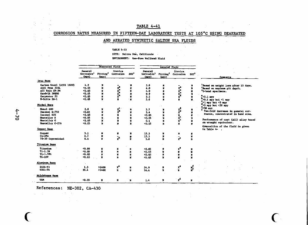
TABLE 4-41 CORROSION RATES MEASURED I N FIFTEEN-DAY LABORATORY TESTS AT 1 0 5 O C USING DEAERATED
f U 0
Iron Base Carbon S t e l (AISI 1020) AISI Type 316L MI Type CF-m &odvik 3m60 Carpenter 20 E-Brite 26-1
Nickel Base Hone1400 Incoml x-750 Inconel 625 Eastalloy S Eaatelloy G Hawelloy C-276
Copper Bane Copper Cu-Za 7&30 Cupronickel
Titanium Bone T i t a n i u Ti-1.7W Ti-1.5Nl Ti-1OV
Aluminum Bane 2024-T3 6061-T6
AND AERATED SYNTHETIC SALTON SEA FLUIDS
TABLE 5-33
SITE: salton sei . California . FWIR0N"T: Cas-Ree Wellhead Fluid
Deaernted Fluid Aerated Fluid
Corrosion' pit t ing' Corrosion SCC' Corrosion' Pitting' Corrosion SCC' G e n e r a l Crevice G e n e r a l Crevice
(mm) (mw) (1DJ) (mw) Colments
4.2 eo. 05 <o. 05 eo.05 (0.05 <O. 05
2.8 (0.05 <O. 05 <o. 05 CO. 05 CO.05
3.1 2.7 0.6
eo. 05 <0.05 <o. 05 <o. 05
1.3 30.4
(0.05
N N N N N N
N N N N N N
N N N
N N N N
71400 ,1400
N
;. X' X' X8 N
$ N N N N
N
2
N N N N
X' N
N
N 5.8 N 4.0 N 4.0 N 0.9 N 2.2 N 3.6
N 3.7 N 3.4 N <O. 05 N a.05 N 0.1 N <0.05
N 12.5 N 13.3 N 5.8
N <0.05 N <o. 05 N (0.05 N <0.05
N 34.9 N 56.6
N - N Xe N X=
5 N I 11 N
$ N N
i N N
N N N XC
N N N - N XC
N xa N N N N N w
N Xe N N
N 1.4 N P
N N N 'U-bmd npecfrcll..
N
'Boned on weight loan after 15 daw. 'Bnasd on maximum p i t depth.
N N 30.1 spy
.>0.1 mpy but <1 mpy d" wy but <5 q y
spy but rPY f>mmIm
Ten-fold incruse in general cor- rosion. concentrated In bend aren.
Performance of cast (MI) alloy based on wrought equivalent. Composition of the f luid is given in Tnble 4- .
N N
N N N
N
References: NE-302, CA-430
b, r a t e s i n aerated f l u i d were greater than 50 mpy. cracking w a s not observed i n t e s t s with e i t h e r aerated or nonaerated f lu ids .
Stress corrosion
Nickel Based Alloys
Inconel 625, Hastelloy S , Hastelloy G and Hastelloy C-276, and Inconel X-750 had uniform corrosion r a t e s l e s s than 0.05 mpy i n deaerated f lu id . Monel 400 did l e s s well (2.8 mpy). Aeration grea t ly increased the corrosion of Inconel X-750. The uniform corrosion rates of t he other nickel-.based al loys were not affected much by aerat ion.
No p i t t i n g or stress corrosion cracking was observed i n Both'Monel 400 and Inconel X-750 experienced
Only Inconel 625 and e i the r environment. some crevice corrosion i n nonaerated media. Hastelloy C-276 did not suf fe r crevice at tack i n aerated f l u i d .
Copper Based Alloys
Copper and Cu-2Fe a l l o y were f a i r l y r e s i s t a n t t o general corrosion in nonaerated media. s ion r a t e s by a fac tor of four. was observed i n e i t h e r f lu id .
No p i t t i n g o r crevice corrosion
70-30 cupronickel w a s more r e s i s t a n t t o uniform corro- s ion (0.6 mpy) i n nonaerated f l u i d , but aerat ion caused a ten- fold increase i n the uniform corrosion rate. It w a s subject to crevice corrosion i n both f lu ids .
/
These t e s t s were i n HZS-free f l u i d . Experience has
shown t h a t copper-based a l loys , especial ly cupronickels, a r e se- verely attacked i n f l u i d s con tab ing H2S (MI-305).
42.7 1
!
Titanium Based Alloys
All four titanium alloys were resistant to uniform cor- rosion, pitting and stress corrosion cracking in both aerated and deaerated fluid. Commercially pure titanium showed ~0.1 mpy cre- vice corrosion in aerated fluid. No other crevice corrosion was observed.
Aluminum Based Allovs
These alloys are not suitable for exposure to Salton Both 2024 and 6061 alloys pitted.badly Sea geothermal fluids.
in nonaerated fluid. The pitting rate, calculated from pit depth after fifteen days, was >1400 mpy. Crevice corrosion of 2024-T3 was severe (>50 mpy). A ten-fold increase in uniform corrosion rate in the stressed area of the U-bend specimens was noted in tests with aerated fluid, though no cracks were observed.
Molybdenum Based Alloy
TZM was the only dolybdenum based alloy tested, Uniform corrosion was very slight (c0.05 mpy) in deaerated fluid; no lo- cal corrosion or stress corrosion cracking was detected. Aera- tion increased general corrosion to 1.4 mpy and significant cre- vice corrosion (>5 mpy but <50 mpy) occurred. No stress corro- sion cracking was observed.
4.6.2 Results of Field Tests at Well Magmamax No. 1
Three test programs have been conducted at Well Magmamax No. 1 in the Salton Sea KGRA. tative observations of corrosion after 30-day exposures of cou- pons in wellhead fluid.
One test series resulted in quali-
In the second program specimens were
tested in two 15-day test periods at the Bureau of Mines thermal Loop Experimental Facility. seven process streams typical of a dual flash binary power cycle. Uniform corrosion and pitting rates were measured, and crevice corrosion and stress corrosion cracking observations were made. The third test program was conducted at Lawrence Livermore Lab- oratory's (LLL) field test station. The tests employed an aci- dified mixture of steam and brine from Magmamax No. 1. of tests were done with the acidified fluid. stress corrosion cracking and erosion-corrosion of specimens ex- posed to two-phase expander nozzle discharge. series, uniform corrosion rates were measured electrochemically in 16-20-hour tests using exhaust fluid from the expander nozzles.
Geo- These tests were done in
Two kinds One series examined
In the second
I
I
Table 4-42 shows the physical characteristics and chemi- cal composition of fluids from three wells in the Salton Sea KGRA. The table indicates the range of temperature, pH, and chemical composition for wells in the resource area. The data for well Magmamax No. l.(middle column) are for flashed fluid. Limited *
data are available describing the characteristics of fluids used in the three field test programs. of fluids used in the field tests are somewhat different from those given in Table 4-42. described in the following sections.
The composition and temperature
The test conditions and results are
4.6.2.1 Qualitative Corrosion Tests in Wellhead Fluid
Coupons of ten alloys (carbon steel, Type 316 L, E-Brite 26-1, Haynes Alloy 20 Mod, Carpenter 20Cb3, Inconel Alloy 625, Hastelloy G, Hastelloy C-276, cammercially pure titanium, TiCode 12) were exposed to wellhead fluid from Magmamax fl for 30 days (SY-029). not include data on fluid composition.
Published information about the test procedures did
w . I
4-73
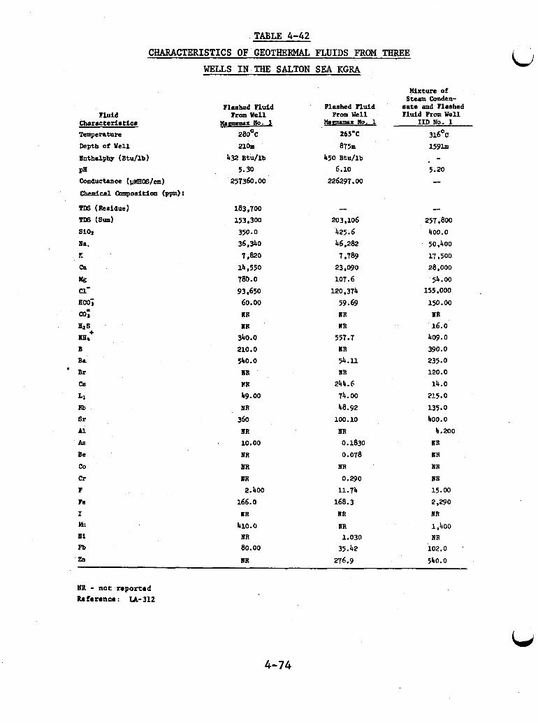
TABLE 4-42 CHARACTERISTICS OF GEOTHERMAL FLUIDS FROM THREE
WELLS IN THE SALTON SEA KGRA
Fluid Characteristic# Temperature Depth o? Well
Bnthdphy (Btu/lb)
PE conductance (@CS/CIU)
chemical Camposition ( P P I :
TDS (Residue) Trs sum) si02
Ea. p.
ca lag c1- Em; a; 4 8
mb+ B Ba
Br cs
L1 Rb Sr Al As Be co C r
F Fe I bkl Ei pb
zn
Flashed Fluid Irom Well
lfa(lclmmau Ho. 1 28OOC 21om
432 Btu/lb 5.30
257360.00
183,700 1539300 350.0 36,340
14,550 780.0 93,650 60.00
7,820
UR UR
340.0 210.0 540.0
UR
WR
49.00 ER
360 UR 10.00 UR
UR IOR 2.400
166.0 ER
410.0 ER 80.00
nR
Flashed Fluid Prom Well
&mnaIMx NO. 1
265'C
875m 450 Btu/lb
6.10 226297.00
203,106 425.6 46,282
1,789 23,090 io?. 6
120.314 59.69 UR NR
557.7 UR 54.11 ER
244.6 74.00 48.92
100.10 UR 0.1830 0.078
HR 0.290
11.74 168.3
NR
UR 1.030
35.42
276.9
Uxture of Steam Conden-
sate and Flashed Fluld From Well
IID No. 1
316'~
1 5 9 h - 5.20 --
e
257,800 400.0 50,400
17,500 28,000
155,000 51.00
150.00 IIR 16.0
409.0 390.0 235.0 120.0 14.0
215.0
135.0 400.0
4.200 ER BR
ER UR 15.00
2.290 n R
1,400 NR
102.0 540.0
IPB - not reported Reference : LA-312
4-74
The carbon steel coupon exhibited the highest corrosion rate. It was visibly sxdaller at the end of the test and disinte- grated when handled. The coupons were not descaled, so weight loss data could not be used to calculate uniform corrosion rates. None of the stainless steel, nickel based, or titanium alloys appeared to have suffered significant corrosion. Type 316 L, Haynes Alloy 20 Mod, Carpenter 20Cb3, and E-Brite 26-1 were pitted. No pitting was observed on the otherspecimens.
ki
4.6.2.2 Corrosion Rates Measured in Seven Process Streams at the Geothermal Loop Experimental Facility
Corrosion rates were measured in two 15-day tests con- ducted at the Bureau of Mines' Geothermal Loop Experimental Fa- cility (GLEF). The test facility employs fluid from well Magma- max No. 1 in seven process streams typical of those in a dual flash steam binary power cycle (wellhead, first and second flash steam, scrubbed first and second flash steam, and first and second flash fluids). Fluid characteristics for the seven pro- cess streams are summarized in Table 4-43.
Coupons of thirteen commercially available alloys were tested for weight loss and evidence of pitting and crevice corro- sion. to minimize the extent of crevice areas. Stress corrosion crack- ing was studied by microscopic examination of a punch area. samples were examined optically for evidence of local corrosion or cracking. Weight loss was measured after descaling, and pit depths were measured with an optical micrometer.
The coupons were fastened to rods using washers designed
All
Rates of uniform corrosion and pitting calculated from maximum weight loss and pit depth are given separately for
4-75
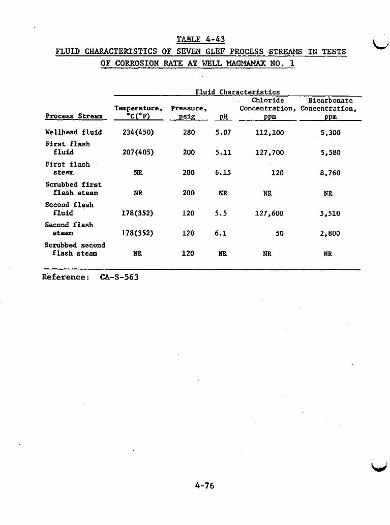
TABLE 4-43 FLUID CHARACTERTSTICS OF SEVEN GLEF PROCESS STREAMS I N TESTS
OF CORROSION RATE AT WELL MA(72UMAX NO. 1
Process Stream
Wellhead f l u i d
F i r s t f l a s h f l u i d
F i r s t f l a s h steam
Scrubbed first f l a s h steam
Second f l a s h f l u i d
Second f l a s h steam
Scrubbed second f l a s h steam
Fluid Charac te r i s t ics
Temperature, Pressure, Concentration, Concentration, Chloride Bicarbonat e
'C('F) p s i ? pH ppm ppm
234 (450) 280 5.07 112,100 5,300
207 (405) 200 5.11 127,700 5,580
NR 200 6.15 120 8,760
NR 200 NR NR NR
178 (352) 120 5.5 127,600 5,510
178(352) 120 6.1 50 2,800
NR 120 NR NR NR
Reference: CA-S-563
4-76
i
materials in each process stream in Tables 4-44 through 4-50. Crevice corrosion detected -in areas where coupons were secured is indicated by X (detected) or N (not detected). Stress corrosion cracking is shown in the same way. significantly different uniform corrosion rates were measured in separate fifteen-day tests. cluded in the table of results.
In several process streams,
In such cases, both rates are in-
The results in Tables 4-44 through 4-50 indicate that pitting did not occur in tests of nickel and titanium alloys. While the tests were not designed to measure stress corrosion cracking, intergranular corrosion was observed for AIS1 Type 316 L.
Although precautions were taken to minimize crevice areas at coupon fastenings, crevice corrosion occurred on the iron-based alloys in all seven streams and on Hastelloy S in scrubbed second flash steam. were observed between ceramic insulators and metal coupons. pitting corrosion occurred in thepe areas, the pits were deeper than the pits in noncrevice areas. least frequently in materials exposed to wellhead fluid and most frequently in materials exposed to scrubbed second flash steam.
Both pitting and uniform corrosion When
Crevice corrosion occurred
For both 15-day test series, the nickel alloys, the titanium alloys, and alloy 29-4 and alloy 6X stainless steels had the greatest resistance to uniform corrosion in all streams. Measured rates were less than 0.1 mpy. E-Brite 26-1 and Type 316 L stainless steels had excellent resistance to general corro- sion (less than 1 mpy) in all streams. Type 430 stainless steef had excellent corrosion resistance in all environments except the wellhead fluid and the scrubbed steam environments, where the corrosion rate was 1 to 5 mpy. The 1020 carbon and 4130 alloy
lj
4-77
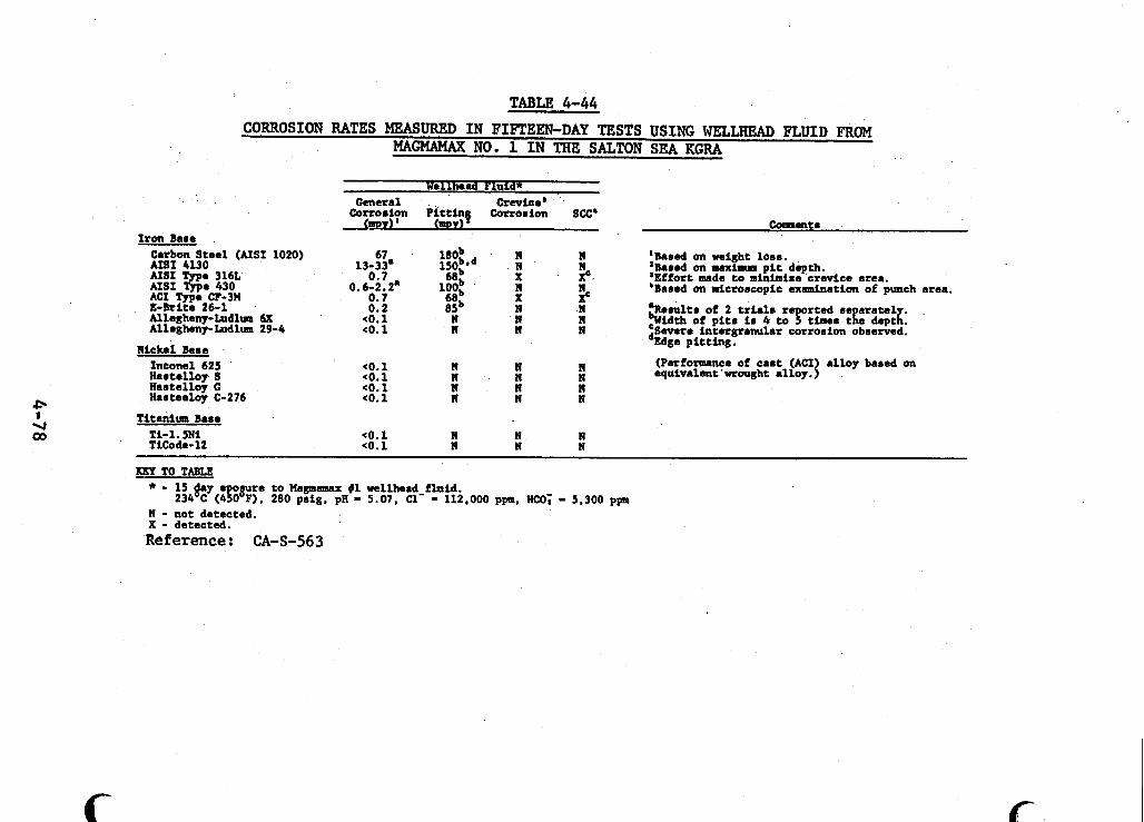
TABLE 4-44 CORROSION RATES MEASURED I N FIFTEEN-DAY TESTS USING WELLHEAD FLUID FROM
MAGMAMAX NO. 1 I N THE SALTON SEA KGRA
Iron Bare Carbon Steel (AISI 1020) AISI 4130
%f %e 430
E - b i t e 26-1 Allegheny-Ludlum 6X Allegheny-Ludlum 29-4
e 316L
ACI m e CF-3H
Nickel Bare Inconel 625 Rartelloy S Hartalloy G Harteeloy C-276
Wellhead Pluld* Gcneral Crevice'
Corroriyn Pi t t ing Cortorion Sa' <my) mDY)
67 180b n n 5, 5
13-33. i50bpd n 0.7 6Eb X
0.6-2.2. 100; n
<o. 1 n X n n n
3 0.7 0.2
<o. 1 n n I
eo. 1 n n n <o. 1 n n n <o. 1 n n n eo. 1 n n n
Titanium Base Ti-1. 5 N i (0.1 n n n Ticode- 12 eo.1 n n n
c
-8lktE
'Bared on weight loor. 'Bared on maxiarus p i t depth. 'Effort made t o minimize crevice area. 'Bared on aicrorcopic examination of punch area.
aRerultr of 2 t r ia l . reported re a ra t e l bwidth of p i t r ir 4 t o 5 timer tL daptg: 'Severe intergranular corrorion obrerved. *Edge pit t ing.
(Performance of ca r t (ACI alloy bared on equivalent 'wrought alloy. {
KEY TO TABLE * - 15 day e omre to Magmamax $1 wellhead f luid.
1 - not detected. X - detected.
234 c ( 4 8 0 0 ~ ) . 280 prig, pn - 5.07, a- - 112.000 ppm. nco; - 5.300 ppa
Reference: CA-S-563
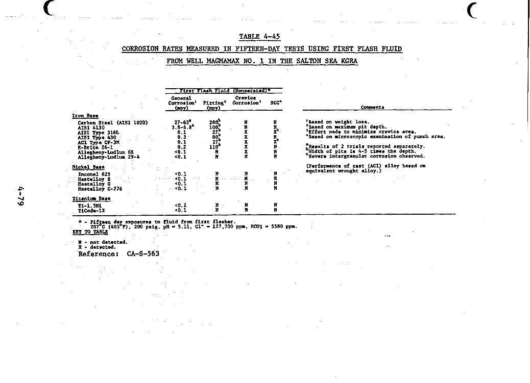
. . - . . ... , . . ~ ~ ~
. -. . I ~ - - .~ ~ . . . . .. ... . - - . . ~ . . . .
TABLE 4-45
CORROSION RATES MEASURED I N FIFTEEN-DAY TESTS USING F I R S T FLASH FLUID
FROM WELL MAGMAMAX NO. 1 I N THE SALTON SEA KGRA
Firs t Flash Fluid (Nonaerated)*
COtrOrf~d pitting' Corrosion' see' General Crevice
(mpY 1 (mpr 1 Iron Base
Carbon Steel (AISI 1020) AISI 4130 AISI Type 316L AISI me 430 ACI Tme CP-3M E - B r i t e 46-1 Allegheny-Ludlum 6X Allegheny-Ludlm 29-4
27-62' 3.8-6.8'
0.1 0.2 0.1 0.2
<0.1 (0.1
2aob loob %Ob
l l O b
27b
27b
n
N
3 x N N
N N N
Nickel Bare <o. 1 N N N
N N N
(0.1 <o. 1
Inconel 625 Hastallby S Hastelloy G
n N N
Rastelloy C-276 (0. 1 N N N
C m e n t s
:Based on weight loss.
'Effort made t o minimize crevice area. *Based on microscopic examination of punch area.
:Results of 2 t r i a l s reported separately. ,Width of p i t s is 4-5 times the depth. Severe intergranular corrosion observed.
(Performance of cast (ACI) alloy based on equivalent wrought alloy.)
Based on maximum p i t depth.
Titanium Base <o. 1 N N N
TiCode- 12 (0.1 N B N Ti-l.5Ni
* - Fifgeen d8g exposurea ta f lu id from f i r s t flasher. 207 c (405 P). 200 pr ig , pH - 5.11, C1' - 127.700 p p , Urn; - 5580 ppm.
KEYTOTABLE
N - not detected. x - detected. Reference: CA-S-563
c.
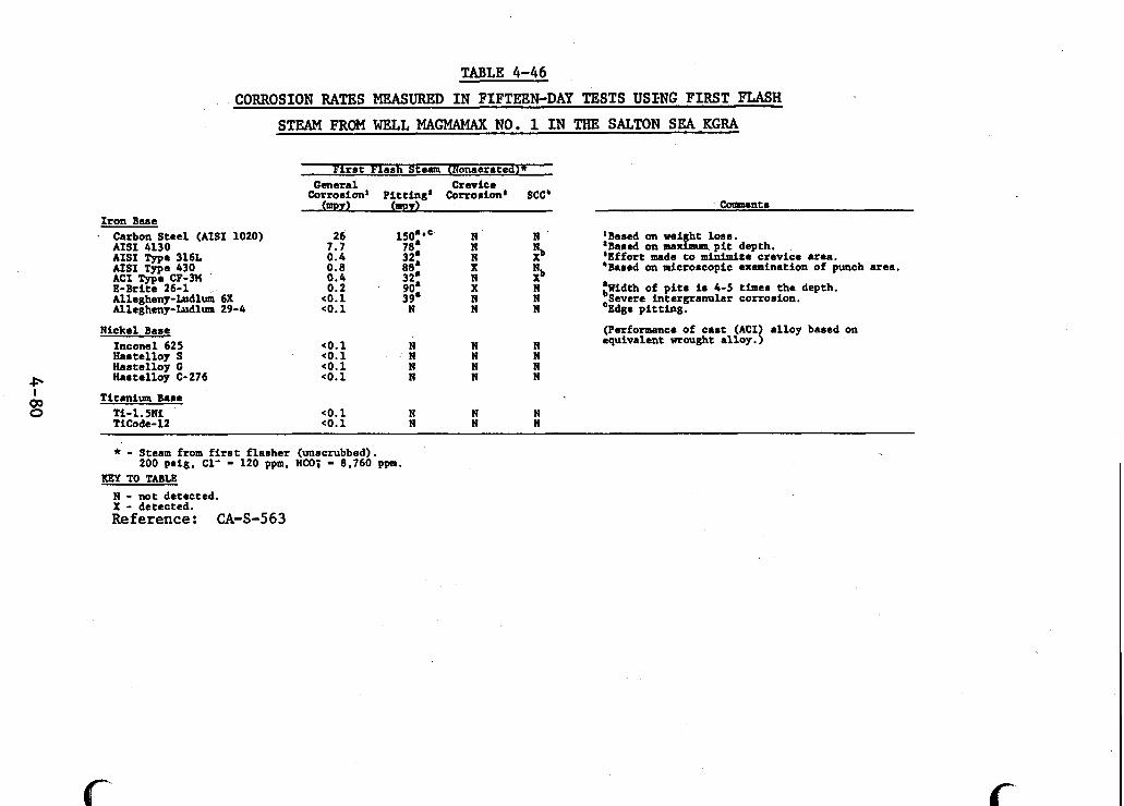
TABLE 4-46
CORROSION RATES MEASURED I N FIFTEEN-DAY TESTS USXNG FIRST FLASH STEAM FROM WELL MAGMAMAX NO. 1 I N THE SALTON SEA KGRA
F i r r t Flarh Steam CNonaerated)x
Corrosion' Pitting; Corrorion' SCC' General Crevice
mPY 1 mPY) ComPcntr Iron Bare . Carbon Steel (AISI 1020) 26 150' ' N N 'Bared on weight lo r r .
'Bared on maximum p i t depth. 'Effort made to minimize crevice area. 'Bared on microrcopic examination of punch area.
3 AISI 4130 7.7 70' N AISI Type 316L 0.4 32: N AISI Twe 430 0.0 00 X N.
E-Brikb 26-1 Alleghetay-Ludl& 6X Allegheny-Ludlum 29-4
Nickel Bare Inconel 625 Hartellop S Hartelloy G
P Hartelloy C-276
Ti tan im Bare
TiCode-12
I 03 0 Ti-1.5191
0.4 32. N XD 0.2 90' X N :Width of p i t s i s 4-5 timer the depth.
<o. 1 39' N N Severe intergranular corrorion. eo. 1 N N N 'Edge pit t ing.
(Performance of car t (ACI) alloy bared on equivalent wrought alloy.)
CO. 1 N N N CO. 1 N N N co.1 N N N <o. 1 N N N
CO. 1 N N N <o. 1 N N N
* - Steam from f i r s t f larher (unrcrubbed). 200 prig. C1' - 120 ppm, HCOj - 0,760 ppm.
KEY TO TABLE N - not detected. X - detected. Reference: CA-S-563
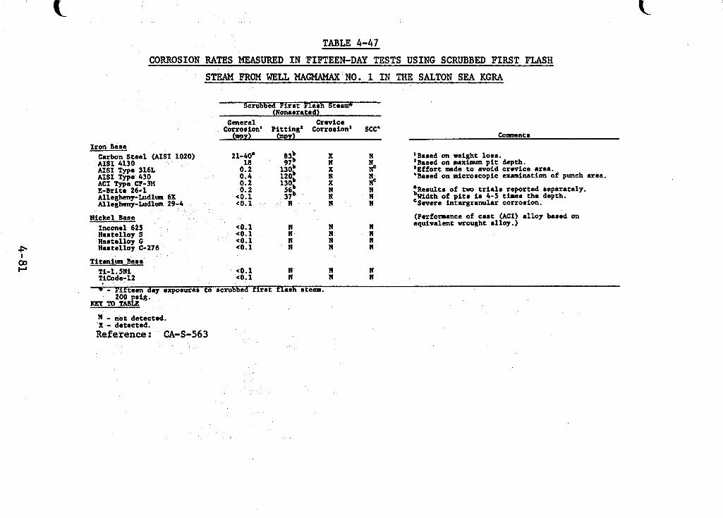
. . . . . . . .... . .., I .. -. . . . . ... . . . ~~~~ ~ . . . .... .. ~_ ._~ ~ ".. ~, - . . - . . . *
P 03 I-'
I
TABLE 4-47 CORROSION RATES MEASURED I N FIFTEEN-DAY TESTS USING SCRUBBED FIRST FLASH
STEAM FROM WELL MAGMAMAX NO. 1 I N THE SALTON SEA KGRA
Scrubbed F i r r t Flarh Steam* (Nonaeratad)
General Crevice Corrorion' Pitting' Corrorion' Scc'
arpY) U W ) Conunentr Iron Base
Carbon Steel (AIS1 1020) AISI 4130 AISI Type 316L A I S I T w e 430 ..__ - ACI *e c p - 3 ~ E - B r i t s 26-1 Allegheny-fudlum 6X Allegheny-fudlura 29-4
Hickel ,Bare Incanel 625 Hartalloy S Hastelloy G Haatelloy C-276
Titmitm Bare
TiCode-12 Ti-1.51%
Titmitm Bare
TiCode-12 Ti-1.51%
21-40. 18
0.2 0.4 0.2 0.2
c0.1 <O.i
*o. 1 *o. 1 < O . l eo. 1
eo.1 eo. 1
19 n
n n n n n n
n n
n N
19 N
n n Nc 5 n w n
n n n n
n n
'Bared on weight loor. 'Bared on maximum p i t depth. 'Effort made to avoid c rwice area. 'Bared on nicrorcopic examination of punch area.
tReml t r of tua t r i a l 8 reported reparately. ,Width of p i t a i r 4-5 times the depth.
(Performance of ca r t (ACI) alloy bared on equivalent wrought alloy.)
Swerc intergranular corroafon.
* - Fifteen day exporurcr t o acrubbed f i r r t flaah rteam. 200 psig.
REY TO TABLE
I - not detected. 'X - detected. Reference: CA-S-563
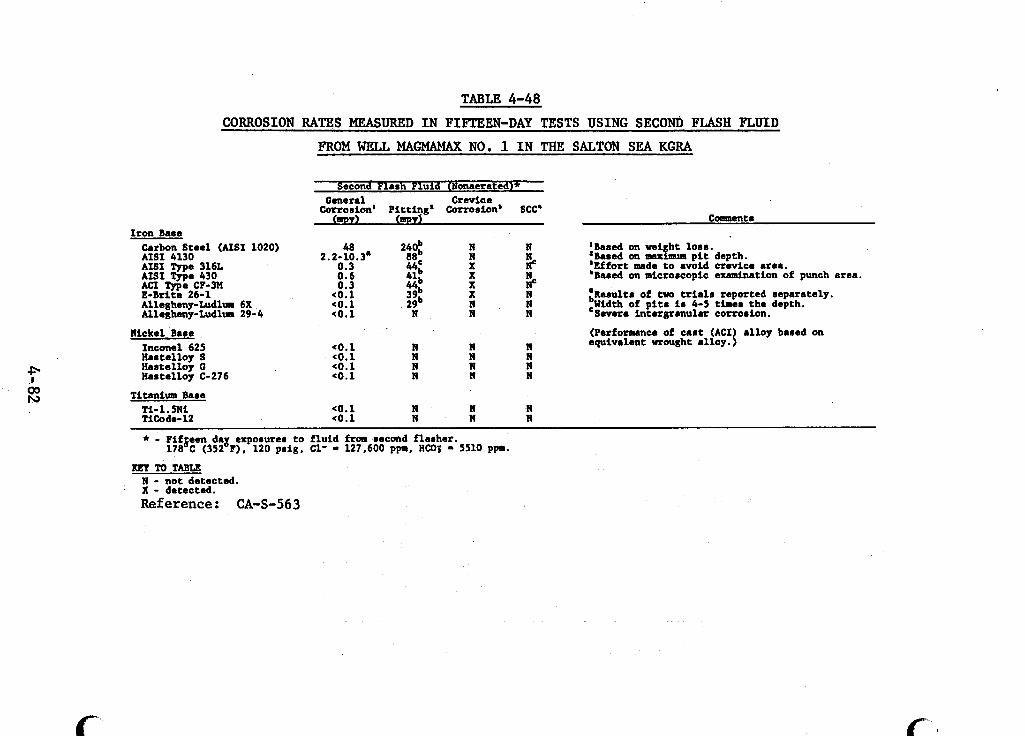
. . . . , . ..... ~. . ..” -. ..___ ,
TABLE 4-48
Iron Bare
CORROSION RATES MEASURED I N FIFTEEN-DAY TESTS USING SECON’b FLASH FLUID
FROM WELL MAGMAMAX NO. 1 I N THE SALTON SEA KGRA
Second Flash Fluid (Nonaerated)*
Corrorion’ Pitting* Corrorion’ SCC’ General Crevice
QUY) W Y l Coenuent 8
Carbon Steel (AISI 1020) 48 240b N N ’Bared on wi h t lorn. ‘Bared on -!mum p i t depth. ‘Effort made t o avoid crevice area. ‘Bared on microrcopic examination of punch area.
:Rerult. of fwa trial8 reported reparately. ,Width of p i t s i r 4-5 timer the depth.
# #
AISI 4130 2.2-10.3. 8ab N AISI Type 316L 0.3 44= X AISI Type 430 0.6 41b X A C I Type CF-3M 0.3 44b X E-Br i te 26-1 eo.1 39b X N
Allegheny-Ludlrmr 29-4 eo.1 N N
Inconel 625 eo.1 N Hamtelloy S (0.1 N N N Hartalloy G eo.1 N N N Hartalloy C-276 eo.1 N N N
Ti-1.5Ni eo.1 N N il TiCode-12 eo.1 N N N
N N
N N equivalent wrought alloy. { N Severe intergranular corrorion.
Alleghmy-Ludl~~~ 6X eo.1 2gb
Nickel Bare (Performance of cart (ACI alloy bared on
Titanium Bare
* - Fifgeen dag exparurea t o f lu id frca recond flasher. 178 C (352 F), 120 prig, C1- - 127,600 ppp. HCO; - 5510 p p .
m To TABU N - not detected. X - detected. Reference: CA-S-563
c
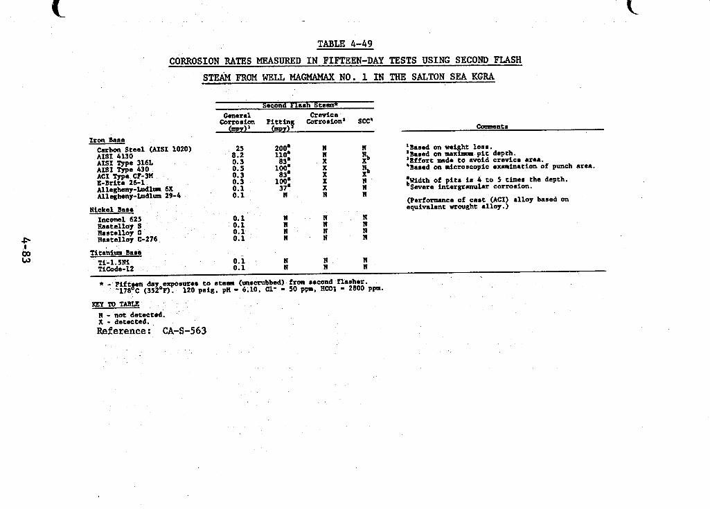
TABLE 4-49 CORROSION RATES MEASURED IN FIFTEEN-DAY TESTS USING SECOND FLASH
ST& FROM WELL MAGMAMAX NO. 1 IN THE SALTON SEA KGRA
Second Flash Steam* General Crevice corrosion Pit t ing Corrorion' SCC'
(my) (mpt) Ccmwnts
Iron Base _ _ ~ Carbon Steel (AISI 1020) AISI 4130 AISI Tme 316L Ais1 *e 430 ACI Type CF-3M E-Brltite 26-1
l icke l Base Inconel 625 Hasteltoy S Bastellay 0 Bastalloy C-276
Titanium Baee
25 8.2 0.3 0. s 0.3 0.3 0.1 0.1
0.1 0.1 0.1 0.1
200. 110. 83'
100. 83.
100. 37. n
n n n n
0.1 n A
Ti-1 .%?I Ticode-12 0.1
n n X X X X X A
n n n n
n n
n n n n
n n
:Based on weight loss.
'Effort made to avoid crevice area. 'Bared on microscopic examination of punch area.
:Width of p i t s is 4 t o 3 times the depth.
(Performance of cast (ACI) alloy based on equivalent wrought alloy.)
Based on maximum p i t depth.
Severe intergranular corrosion.
* - Fiftgen day exposurer t o steam (unscrubbed) from second flasher. '178 C (352'F). 120 psig, pH - 6.10, C1' - 50 ppm, HCO; - 2800 ppa.
KEY m TABLE n - not detected. '
X - detected. Reference: CA-S-563
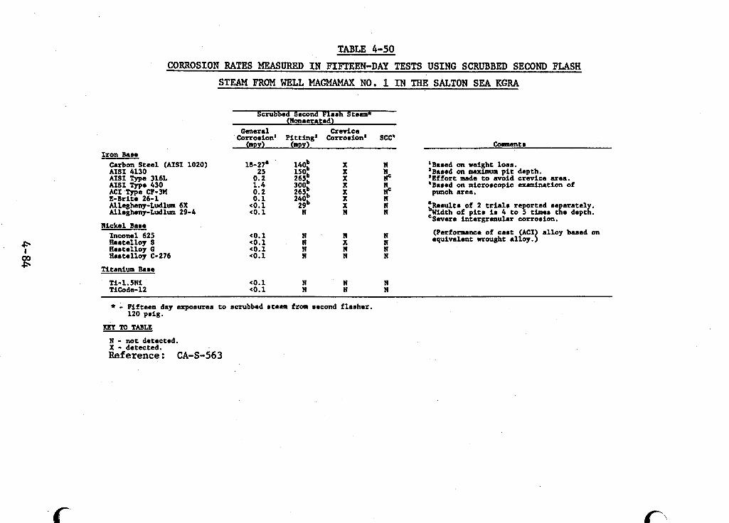
f
Iron Base
TABLE 4-50
CORROSION RATES MEASURED IN FIFTEEN-DAY TESTS USING SCRUBBED SECOND FLASH
STEAM FROM WELL MAGMAMAX NO. 1 IN THE SALTON SEA KGRA
Carbon Steel (AISI 1020) AISI 4130 . .__ - . - - . AISI Tme 316L
Scrubbed Second Flanh Steam*
Corrorion' Pitting' Corrorion* see'
(Nonaerated) General havice
QPY) mPY)
18-27. 25
0.2 1.4 0.2 0.1
Allegheny-Ludlum 6X (0. i 29" X N Allegheny-Ludlum 29-4 (0.1 N N n
N i c k e l Bane Inconel 625 Hantelloy S tiantelloy G liartelloy C-276
Titanium Bare
Ti-1.5Ni TiCode-12
(0. 1 N N N eo.1 N X N (0. 1 N 19 N eo.1 N N n
eo. 1 N N N (0.1 n N N
Conmentr
'Baned on weight lose. 'Bared on maxlmm p i t depth. 'Effort made t o avoid c r w i c e area. 'Bared on microrcopic ex.nination of
b R e n u l t n of 2 trial. re orted re a ra t e l :Width of p i t# ir 4 t o 5 times t te deptg:
punch area.
Severe intergranular corrorion.
(Performance of ca r t (ACI) alloy bared on equivalent wrought alloy.)
* - Fifteen day exposurer t o scrubbed rteam from necond flaaher. 120 pnig.
KEY M TABLE
N - not detected. X - detected. Reference : CA-S-563
i
! i
I
!
I !
I I
! I
1
! t
/
1 i i I : ! 1
1 i I I
I
1
I i
i I #
i
I I i
steels had the poorest corrosion resistance in all streams and L d
were more severely corroded in the fluids than in the steams.
In several of the streams, the average corrosion rates of 1020 carbon steel, 4130 alloy steel, and 430 stainless steel were significantly different for each of the two 15-day series of corrosion tests. However, the corrosion rates for each set of metal samples in any one stream for a single 15-day test series were in good agreement. each 15-day test series were significantly different, both rates are reported.
Where the average corrosion rates of
With the exception of Allegheny-Ludlum 29-4, all of the The 1020
Pitting was more severe in
iron-based alloys were pitted in one or more streams. carbon steel pitted most severely in liquid streams while the alloy steels pitted worse in steam. "clean" steam than in "dirty" steam. four to five times greater than their depths. of attack and indicates that corrosion over the surface of the metal is proceeding faster than penetration into the body of the metal.
4 . 6 . 2 . 3
The widths of the pits were This is a mild form
Tests in Acidified Salton Sea Geothermal Fluid
Lawrence Livermore Laboratory (LLL) has shown that acidification of Magmamax No. 1 fluid to a pH t4.5 will prevent scale formation for "a substantial period of time." The con- centration of HC1 in the acidified fluid is about 200 ppm. LLL has done some materials testing in acidified geothermal fluid from well Magmamax No. 1 and preliminary results have been re- ported (AU-064, TA-136).
The field tests were conducted using a mobile test bed which includes a flash steam separator and.has the capability u
4-85
for producing both pure brine or steam and two-phase mixtures. Test fluids are discharged through two-phase expander nozzles. There are provisions for modifying the test fluids by adding chemicals. atmospheric pressure chambers containing static wearblades.
The test equipment includes simulated turbine cases,
The results of two series of tests are reported here. In one series, corrosion specimens were mounted on the base of the fixed wearblades to test potential turbine materials for re- sistance to erosion, pitting and crevice corrosion, and stress corrosion cracking. Specimens of the alloys to be tested were prepared by bending two strips of each alloy around a mandrel and retaining the sandwich under tension with a clamp. specimens were mounted so that the broad face of the specimen was perpendicular to the expander nozzle discharge. were exposed to acidified brine/steam mixtures at 100°C for periods varying from 7 . 5 to 110 hours. rate was 240 mps (787 fps). The alloys tested and the test conditions are summarized in Table 4-51. the tensile face of the specimens exposed to spray impact are also given in the table. Pitting, cracking and erosion were ob- served. pact showed that much of the pitting was a result of erosion- corrosion. Ti-6A1-4V wearblades.
The
The assemblies
The nozzle discharge Fluid pH varied from 2 . 5 to 4 . 5 .
Qualitative observations about the condition of
Examination of the tensile face not exposed to spray im-
There was no detectable erosion of the edge of the
In the second series of tests, sixteen ferrous and non- ferrous alloys were exposed to acidified nozzle exhaust effluent. Steam had been removed from wellhead fluid in the flash steam separator before discharge through the expander nozzles.
4-86
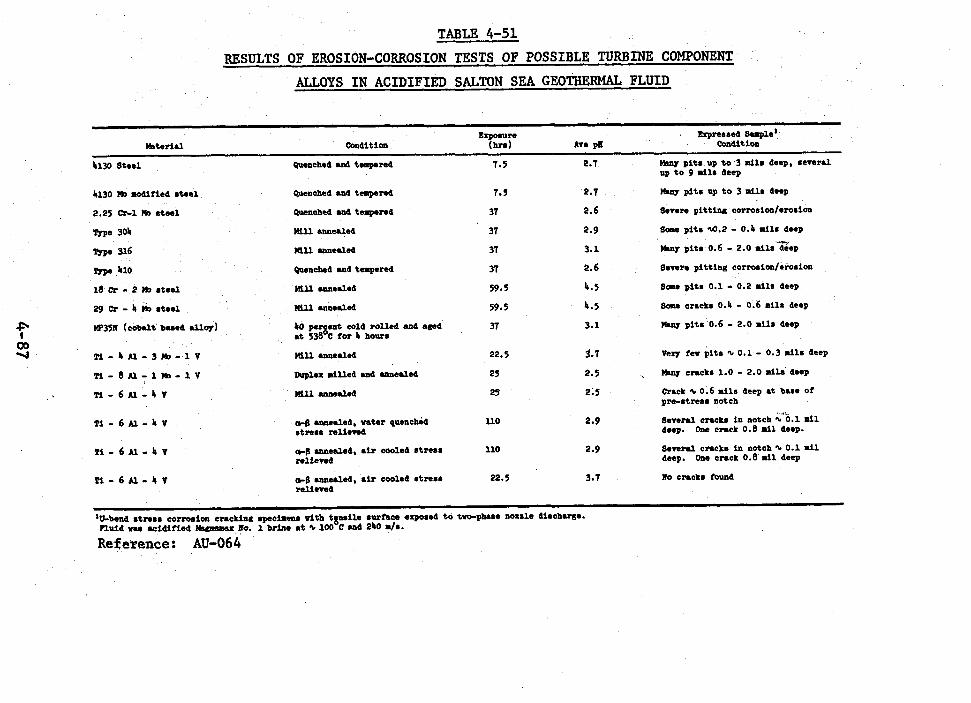
.- . _ . . . __ .... ~_. . . .. ~- _~. . ,. . ~- . ._I . .. ... . . . .. . .. -.. ....... ~~ ~ . - ~ - - ~ -- . .. . . . . . .
TABLE 4-51 RESULTS OF EROSION-CORROSION TESTS OF POSSIBLE TURBINE COMPONENT
ALLOYS IN ACIDIFIED SALTON SEA GEOTHERMAL FLUID
Expressed Suple ' EQterlal Condition b e pII Condit ion
f 00 -I
4130 Steel Quenched sad teap.red
4130 Ma mdif ied s t e e l
2.25 Cr-1 Ho steel
Type 305
Type 316
Type 410
18 cr - 2 nD rteel
29 cr - 4 Mo steel
W35N (cobalt b u e d &or)
T i - k A l - 3 H o - l V
T i - 8 N - l L - l V
T i - 6 N - k Q
~ - 6 f l - h V
T i - 6 A l - S Q
Quenched and tempered
Quenched .md t e q e r e d
M i l l .anemled
M i l l w e a l e d
Quenched and tempered
M l l w e a l &
M i l l annealed
40 percent cold rolled and wed at 538OC fo r 4 hours
M i l l umealed
Duplex milled utb annealed
Mill annealed
+B umealed. mter quench& r t r e r s reliewed
relieved
relieved
annealed, sir cooleb B t r e s S
wealed , sir cooled stress
7.5
7.5
37
37
37
37
59.5
59.5
37
22.5
25
25
l l 0
110
22.5
2.7
2.7
2.6
2.9
3.1
2.6
1.5
5.5
3.1
3.7
2-5
2.5
2.9
2.9
3.7
bbny p i t s up t o 3 mila deep, several up t o 9 m i l s deep
Smy p i t s up t o 3 mils deep
severe pi t t inu corroaion/erosion
6- p i t s d . 2 - 0.4 d l r d-p
m y p i t s 0.6 - 2.0 mils t e p
severe p i t t i a s corrosion/emsion
Some p i t a 0.1 - 0.2 mils deep
scme cracks 0.4 - 0.6 mila deep
bbny p i t s 0.6 - 2.0 mils deep
&my cracks 1.0 - 2.0 mila' deep
Crack I, 0.6 m i l s deep at base of pre-stress notch
Several cracks in notch %%.l m i l dnp .
Several cracks in notch I, 0.1111 deep.
No cmcka found
One crack 0.8 mil deep.
h e Cmck 0.8 mil deep
'&bend strear corrosion cmcking apecimms with t p i t s u r h c e exposed t o tve-pbue nossla d i r chum. n u i d yu 6cidified No. 1 brine a t I, 100 C and 240 4 8 .
Reference: AU-064
Corrosion rates were measured in an electrochemical cell in 16 to 20-hour tests using a Petrolite Instruments Co. cor- rosion rate meter. The meter employs a probe assembly with inter- changeable electrodes fabricated from the test materials. pH of the test fluid was in the range of 2.0 to 4 . 5 , and the tem- perature was 86 to 98OC. corrosion rates. to pitting or other forms of local corrosion. form corrosion rates indicate that some low alloy steels may be suitable for use in low-temperature streams while stainless steels and'nonferrous alloys might be applicable at higher temperatures.
The
Table 4-52 shows the measured uniform The test method does not indicate susceptibility
The measured uni-
4-88
F i
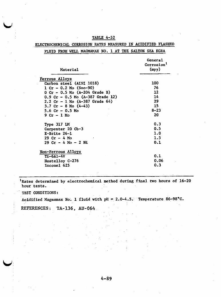
TABLE 4-52
ELECTROCHEMICAL CORROSION RATES MEASURED IN ACIDIFIED FLASHED FLUID FROM WELL MAGMAMAX NO. 1 AT THE SALTON SEA KGRA
Material
Ferrous Alloys Carbon steel ( A I S 1 1018) 1 Cr - 0.2 Ma (Soo-90) 0 Cr - 0.5 Mo (A-204 Grade B) 0.9 Cr - 0.5 Mo (A-387 Grade 12) 2.2 Cr - 1 Mo (A-387 Grade 64) 3.7 Cr - 8 Mo (4-43) 5.6 Cr - 0.5 Mo 9 Cr - 1 Mo Type 317 LM Carpenter 20 Cb-3 E-Brite 26-1 29 Cr - 4 Mo 29 Cr - 4 Mo - 2 Ni
Non-Ferrous Alloys Ti-6Al-4V Hastelloy C-276 Inconel 625
General Corrosion'
(mPY 1 - 100 76 12 14 29 15 8-23 20
0.3 0.5 1.0 1.5 0.1
0.1 0.06 0.3
'Rates determined by electrochemical method during final two hours of 16-20 hour tests. TEST CONDITIONS: Acidified Magmamax No. 1 fluid with pH = 2.0-4.5.
REFERENCES : TA-136, AU-064
Temperature 86-98OC.
4-89
5 . 0 CORROSION MODES FOR METALS IN GEOTHERMAL SYSTEMS
Section 4 presented available data from tests of ma- terials performance in geothermal fluids. Most of these tests measured the rates of uniform corrosion and localized (pitting and crevice) corrosion of coupon specimens, though some tests of stress corrosion cracking of U-bend specimens have been done. The results of these tests are helpful in selecting materials, because they can be used to predict how fast a metal deteriorates uniformly or from pitting at a specific fluid composition, tem- perature, and flow rate. sion rates described in Section 4 do not supply all of the infor- mation needed to specify construction materials for piping, vessels, or process equipment.
But the uniform and localized corro-
There are three reasons they do not tell the whole story. position and process stream characteristics. results do not describe materials performance in streams with different .compositions a temperatures , pressures or flow rates.
First, the corrosion rates are dependent on fluid com- Therefore , the test
Second, metallic construction materials are subject to other forms of attack besides uniform, pitting and crevice corro- s ion.
Catastrophic component failures can occur suddenly
SSC occurs in hard, high strength alloys exposed with little evidence of metal loss due to sulfide stress crack- ing (SSC). under stress to aqueous environments containing even small amounts of H,S. Hydrogen blistering, another form of attack, causes rupture of metallic materials when hydrogen trapped in voids accumulates at a sufficient pressure. treatment or welding can result in intergranular corrosion near
Improper heat
5-1
grain boundaries (weld decay) which causes alloys to disintegrate or lose strength. Dealloying, dissolution of one component of an alloy, is another form of corrosion. corrosion fatigue when cyclic stresses occur in a corrosive en- vironment.
Failures also occur due to
Finally, the rate at which metals deteriorate depends
In practice it is not a metal coupon that fails due on some factors that are not taken into account in tests using coupons. to metal deterioration but a pipe, vessel, pump, or other equip- ment item fabricated from metal. The rate of metal deteriora- tion or the mode of,corrosive attack also depend on fabrication practices, equipment configuration and geometry, and stresses that occur during operation.
This section describes the forms and mechanisms of corrosive attack that can occur in geothermal process streams. These generalizations are especially useful when materials must be specified for conditions at which tests have not been done. If the corrosion rate of a material has4been tested at the stream conditions of interest, this information is still useful. It explains the effects of fabrication practices, equipment con- figuration, and operating stresses. And it identifies some additional ways materials can deteriorate.
The information is presented in three parts. corrosive attack in wellhead and flashed liquid streams are de- scribed first. are described for mile and low alloy steels (Section 5.1), stain- less steels (Section 5.2), titanium alloys (Section 5.3), nickel alloys (Section 5.4), copper alloys (Section 5.5) and cobalt, zirconium and aliminum (Section 5.6). the information about the performance of specific metals in liquid streams given in Sections 5.1 through 5.6.
Modes of
The forms of failure that can occur in liquids
Table 5-1 is a guide to
It summarizes
5-2
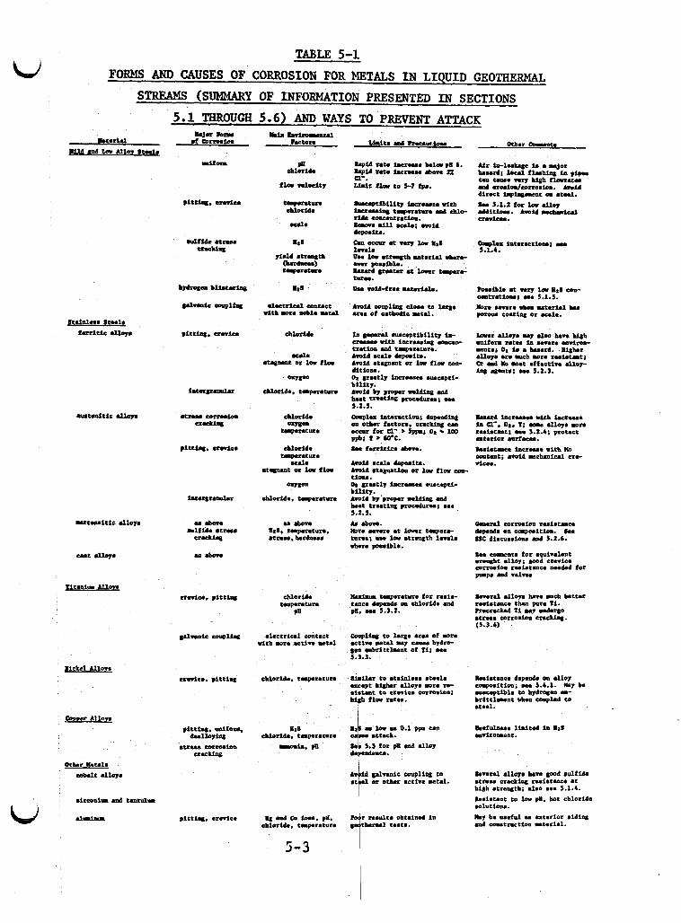
kl TABLE 5-1
FORMS AND CAUSES OF CORROSION FOR METALS I N LIQUID GEOTHERMAL STREAMS (SUMMARY OF INFORMATION PRESENTED I N SECTIONS
5.1 THROUGH 5.6) AND WAYS TO PREVENT ATTACK
chloride
n l f i d e m w -- Id Qsla interactLoru; m u 5.1.4.
llui.u t..puecure for rule- tmce W a d e on chloride and pa. w. 5.3.2.
Senre1 all- have mch better remistme than pure T1. hecracked Ti u y underce *true mrrosion crecklng. (5.3.4)
electrical contact u i t b mre r t iw metal
coupling to large UUI of mre utln Mu1 u). cmue hydro- sen mhrittlment of Tl; ees 5.3.3.
Iulstence depede m alloy amposition; e n 5.4.1. M y be mucepclble to hydrqen a- b r l t t l . r o t uheo coupled t o ec-1.
ahlorid.. r r p n t u n
u La u 0.1 PpI M I attack. b.5 tor pB ani alloy denC..
Lnrrl alloye h v e p o d sulfide e t n u cracking nsistmce et W h etremgth; also H e 5.1.4.
le*lecaut to l o w pa. bot chloride w l u C i o n . . M y be useful u aterior aiding .Id coostruction uteriel.
I &sIVuliC eoupliatg to 1 or other actin wtel.
the information presented fo r each metal, defining the kinds of corrosive at tack t h a t can occur fo r a par t i cu la r metal and the f lu id o r process stream cha rac t e r i s t i c s t ha t determine corrosive- ness. The conditions under which a t tack i s minimized are defined and precautions fo r design , fabricat ion and operation are given,
Materials performance i n condensate (Section 5.7) and steam (Section 5.8) i s t rea ted i n the l a s t two sections. While much of the information given fo r l i qu id streams i n Sections 5.1 through 5.6 i s also applicable t o condensate and steam environ- ments, there a re some addi t ional considerations fo r these streams. Corrosion fatigue and erosion caused by exfo l ia t ion o r droplet impingement are most l i ke ly t o occur in these environments.
1
5-4
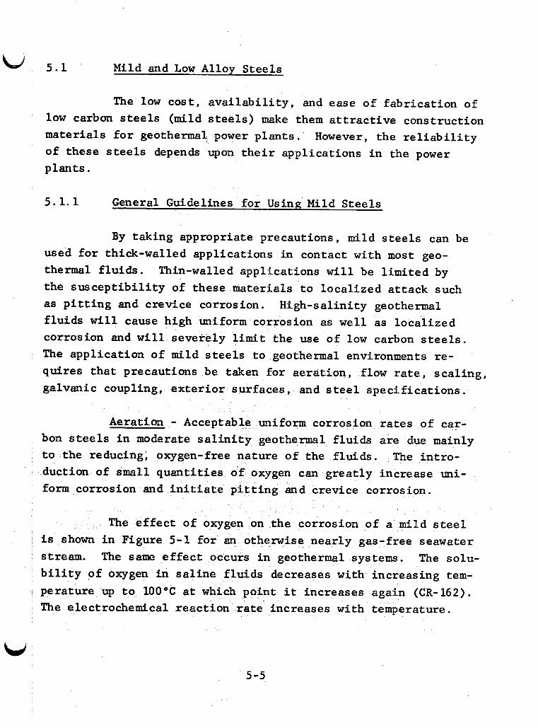
5.1 Mild and Low Alloy Stee ls
The low cos t , a v a i l a b i l i t y , and ease of fabr ica t ion of low carbon steels (mild s t e e l s ) make them a t t r a c t i v e construction materials f o r geothermal power p lan ts . ’ However, the r e l i a b i l i t y of these steels depends upon t h e i r applications i n the power plants .
5 .1 .1 General Guidelines fo r Using Mild Steels
By taking appropriate precautions, mild s t e e l s can be used f o r thick-walled applications i n contact with most geo- thermal f lu ids . Thin-walled applications w i l l be l imited by the suscep t ib i l i t y of these materials t o local ized a t tack such as p i t t i n g and crevice corrosion. f l u ids w i l l cause high uniform corrosion as w e l l as local ized corrosion and w i l l severely l i m i t the use of low carbon steels. The appl icat ion of mild steels t o .geothermal environments re- quires t h a t precautions be taken for aerat ion, flow rate, sca l ing , galvanic coupling, ex te r io r surfaces , and s t e e l spec i f ica t ions .
Aeration - Acceptable uniform corrosion rates of car- bon steels i n moderate s a l i n i t y geothermal f lu ids are due mainly t o the reducing: oxygen-free nature of the f lu ids . The in t ro - duction of small quant i t ies of oxygen can grea t ly increase uni- form corrosion and i n i t i a t e p i t t i n g and crevice corrosion.
Hfgh-salinity geothermal
The effect of oxygen on the corrosion of a mild s teel i s shown i n Figure 5-1 f o r an otherwise nearly gas-free seawater stream. The same effect occurs i n geothermal systems. The solu- b i l i t y of oxygen i n s a l i n e f lu ids decreases with increasing tem- perature up t o 100°C a t which point i t increases again (CR-162). The electrochemical react ion rate increases with temperature.
W 5-5
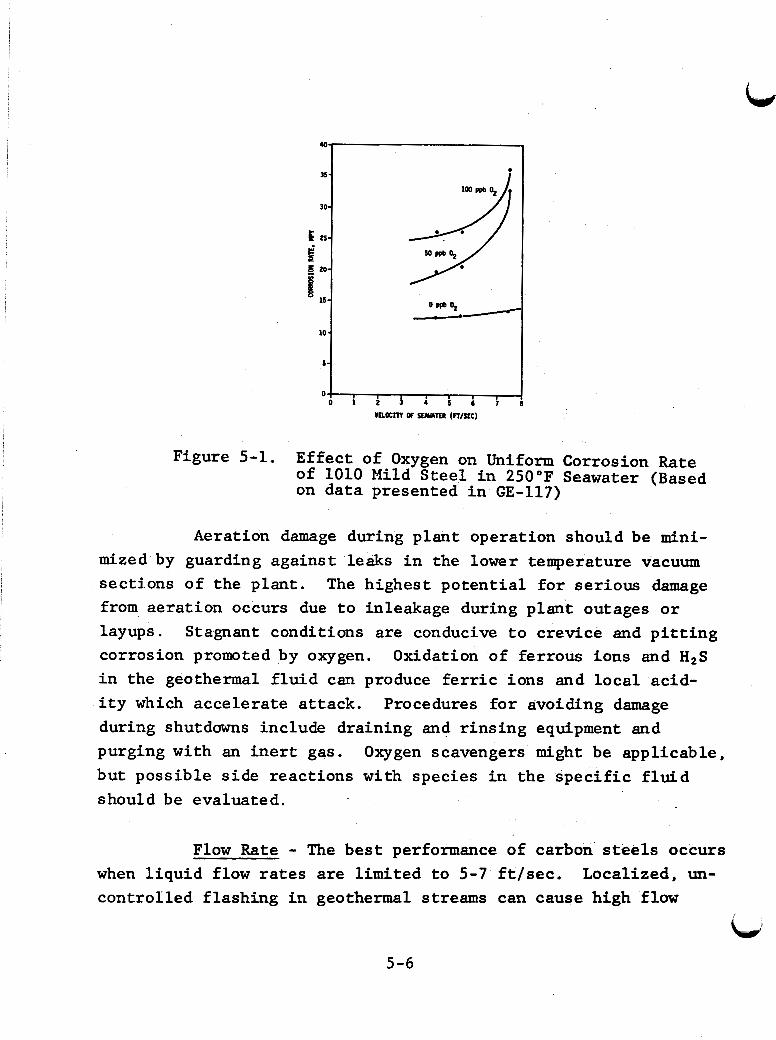
Figure 5-1. Effect of Oxygen on Uniform Corrosion Rate of 1010 Mild Steel i n 250°F Seawater (Based on data presented i n GE-117)
Aeration damage during plant operation should be mini-
The highest po ten t ia l f o r serious damage mized by guarding against leaks i n the lower temperature vacuum sections of the plant. from aerat ion occurs due t o inleakage during p l a n t outages o r layups. corrosion promoted by oxygen. i n the geothermal f l u i d can produce f e r r i c ions and loca l acid- i t y which accelerate a t tack. during shutdowns include draining and r ins ing equipment and purging with an i n e r t gas. but possible s ide reactions with species i n the specific f l u i d should be evaluated.
Stagnant conditions are conducive t o crevice and p i t t i n g Oxidation of ferrous ions and H2S
Procedures f o r avoiding damage
Oxygen scavengers might be applicable,
Flow Rate - The bes t performance of carbon steels occurs when l iqu id flow rates are limited t o 5-7 f t / s e c . control led f lashing i n geothermal streams can cause high flow
Localized, un-
Lid
5-6
W rates in the system. densable gas which can cause impingement attack. in the stream can cause erosion-assisted corrosion. The relative hardness of particle and metal has little effect on this type of corrosion.
This action can produce bubbles of noncon- Entrained solids
Failure of components such as pipe ells has occurred in fluids as diverse as those at Salton Sea and Raft River. These failures are probably caused by the flow conditions noted above. Designs to avoid direct impingement on carbon steels and localized flashing should alleviate these types of failures. Providing li- quid buffer zones may help. Pump impellers, especially for down- hole applications, may be subject to severe cavitation damage. The Con content of many geothermal fluids can cause an apparent vapor pressure that exceeds steam table values by tens to hundreds of psi. Caution in design and material selection is required.
Effects of high velocities are illustrated in Figure 5-2 for seawater at 250'F.
Figure 5-2. Weight-Loss Corrosion Rates of Mild Steel in High Velocity, High Temperature Oxygen-Free Seawater. (Based on data presented in GE-117)
5-7
Scaling - Some nrechanical protect ion against uniform corrosion may r e s u l t from scales formed on s t e e l by prec ip i ta t ion from geothermal f lu ids , but local ized corrosian can a l so occur under the scales . Scales i n geothermal systems are porous and prone t o cracking by d i f f e ren t i a l thermal expansion. sure of the base metal t o a geothermal f l u i d can l ead t o loca l ac id i ty and high chloride concentration s imi la r t o conditions during crevice corrosion. Accelerated at tack by H2S i s in- creased i n ac id ic environments such as t h i s .
The expo-
Attack a t small exposed areas can become more ser ious i f the s t e e l i s galvanically coupled t o a more noble metal. In extreme cases, t h i s concentration of the s t e e l dissolut ion cur- rent can cause perforat ion of thick-walled steel components.
Chemical cleaning solut ions used t o remove sca le should be evaluated careful ly s ince some types (such as inhibi ted HC1) accelerate corrosion of mild steel. Severe at tack can occur if aggressive cleaning solut ion i s trapped i n o r under incompletely removed scale .
*
Galvanic Coupling - Carbon steels w i l l be anodic t o high al loy s t e e l s , o r n i cke l , copper o r t i tanium al loys t h a t may be used for instrumentation, cladding, heat exchanger tubing, and valve and pump t r i m . Galvanic corrosion of the carbon s t e e l can occur when it i s e l e c t r i c a l l y connected t o the more noble metal (e i ther d i r ec t ly o r through grounding) and when both materials are i n contact with the l iqu id stream. Corrosion w i l l be severe when the diss imilar metals a r e c lose together and the area of steel exposed t o the l i qu id i s small compared t o t h a t of the more noble metal. Some noble metals may be subject t o embrittlement when galvanically coupled t o s t e e l .
5-8
A galvanic series chart obtained fo r metals i n degassed seawater a t 225°F i s shown i n Figure 5-3. a given m e t a l w i l l be accelerated when i t i s galvanical ly coupled t o a m e t a l with a more pos i t ive open c i r c u i t po ten t ia l . lar order w a s observed i n Heber geothermal f lu ids during short- term measurements (SY-028). The order of metals i n the series may change with var ia t ions i n cheinistry and temperature. is doubt, the series should be determined experimentally under
I,
The corrosion rate of
A s i m i -
If there
f i e l d conditions.
Exter ior Surfaces - The ex ter ior of mild s t e e l pipes , vessels and s t r u c t u r a l components requires protect ion. and sprays of s a l ine f l u i d combined with a i r and occasional H2S emissions can produce rapid at tack. Protect ive coatings should be used t o minimize uniform and local ized at tack of ex ter ior surfaces. local ized a t tack a t pores or exposed areas.
Leaks
High qua l i ty coatings should be specif ied t o avoid
,Steel Specif ic on - Sulfide s t r e s s cracking and hy- drogen b l i s t e r i n g can be control led t o a large extent by 'use of low s t rength , metal lurgical ly clean and void-free s t e e l (see Sections 5.1.4 and 5.1.5). M i l l s e l e f t on s t e e l can accel- erate p i t t i n g o r crevice corrosion spec ia l ly i n the presence of sulf ides . Effects of low al loy additions t o s t e e l a re dis- cussed i n Section 5.1.2.
5.1.2 Uniform and Localized Corrosion of Mild Steels
Uniform and local ized corrosion are the t w o main modes of corrosion of low strength mild s t e e l s i n geothermal systems. Localized corrosion i n t h i s discussion r e fe r s t o p i t t i n g and crevice corrosion.
r' #
5-9
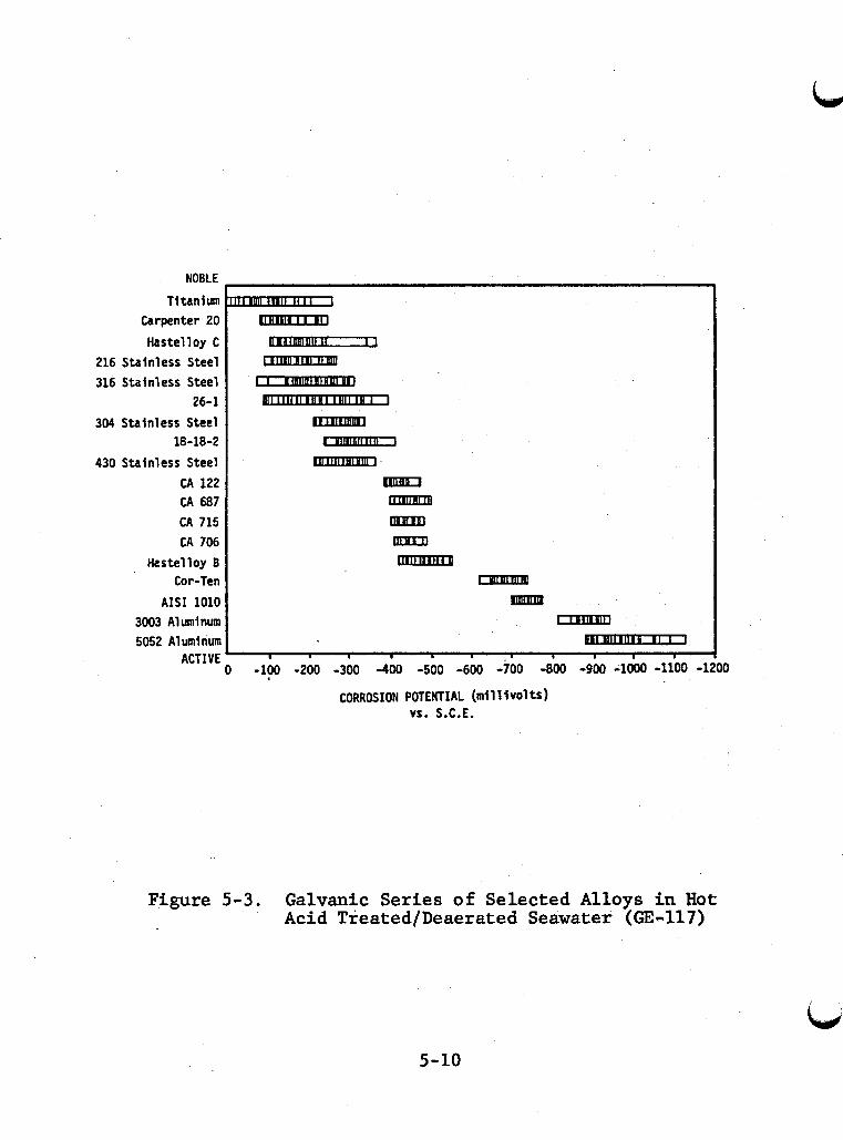
NOBLE Titanium
Carpenter 20 Hastelloy C
216 Stainless Steel 316 Stainless Steel
304 Stainless Steel
430 Stainless Steel CA 122 CA 687 CA 715 CA 706
Hastelloy B Cor-Ten
AIS1 1010 3003 Aluminum 5052 A1 umi num
ACTIVE
26-1
18-18-2
I . I I I
O -100 -200 -300 -400 -500 -600 -700 -800 -900 -1000 -1100 -1,
CORROSION POTENTIAL (millivolts) V f . S.C.E.
Figure 5-3. Galvanic Series of Selected Alloys i n Hot Acid Treated/Deaerated Seawater (GE-117)
3
5-10
Corrosion r e s u l t s f o r mild and low a l loy s t e e l s i n geothermal f i e l d tests are shown i n Table 5 - 2 . i n a wide range of environments, uniform corrosion rates are about 1 t o 10 mpy when the pH i s greater than 6 and the chloride concentration is less than 2%. Localized corrosion occurs t o
Although obtained
some extent i n most f lu ids and becomes predominant i n f l u i d s where uniform corrosion i s less severe.
The relative importance of uniform and local ized corro- s ion depends mainly on pH and chloride concentration. c r i t i c a l pH, uniform corrosion rates a re re la t ively low, and the major problem fo r mild steels i s local ized corrosion. p i t t i n g and crevice corrosion are more severe forms of a t tack than uniform corrosion, p l a in steels should not be considered immune t o a t tack a t high pH values. Chloride ion is the main i n i t i a t o r of local ized at tack. Hydrogen su l f ide can increase the sever i ty of local ized corrosion.
Above a
Since
P i t t i n g and crevice corrosion are similar with regard t o environmental e f f e c t s and material suscep t ib i l i t y . Both forms of corrosion are most of ten associated w i t h the local ized breakdown of a protect ive f i l m on the = ta l surface. t a ry breakdown of t h i s f i l m can r e s u l t i n r a p i d anodic m e t a l d issolut ion a t the exposed area driven by cathodic reactions on the rest of the surface. a high electrochemical driving force. Water o r hydrogen ions may a l so serve as the oxidizing agent, but the driving force i s lower and the exposed area has a b e t t e r chance t o repassivate before growth starts. Once growth s t a r t s , the p i t o r crevice area becomes acidic and chloride ions are transported i n t o the area. Both of these effects discourage repair of the protect ive f i l m and growth can become self-sustaining.
A momen-
Cathodic reduction of oxygen can supply
5-11
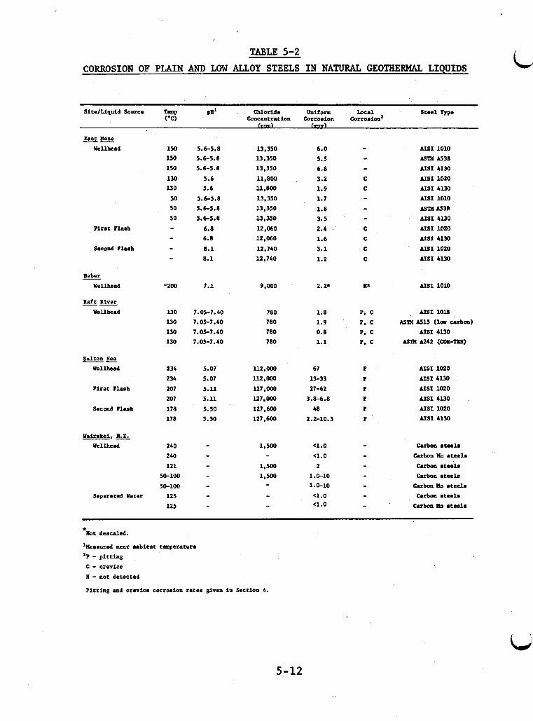
TABLE 5-2
CORROSION OF PLAIN AND LOW ALLOY STEELS IN NATURAL GEOTHERMAL LIQUIDS
Site/liquid Source Temp P" Chloride Uniform local Steel m e ('C) cancentration cattoeion ~orrosion'
V)
East Hesa -- Wellhead
First Flash
Second Flash
Heber Uellhead
Raft River -- Wellhead
Salton Sea -- Wellhead
First Flash
Secmd Flash
Wairekei, N. 2. Wellhead
1
Separeted Water
150 150 150 130 l30 50 50 50 - - - -
-200
130 l30 130 130
234 234 207 207 178 178
240
240 121
50-100 50-100 125 125
5.6-5.8
5.6-5.8
5.6-5.8 5.6 5.6
5.6-5.8
5.6-5.8 5.6-5.8
6.8 6.8 8.1 8.1
1.1
7.05-7.40 1.05-7.40 7.05-7.40 7.05-7.40
5.07 5.07 5.ll 5.11 5.50 5.50
- - - - - - -
l3.350 l3 ,350 13,350 11,800 . 11,800 13.350 13.350 13.350 12,060 12.060 12.740 12,740
9,000
780 780 700 780
112.000 112.000 127.000 127.000 127,600 127.600
1,500
1.500 1.500
-
- - -
6.0 5.5 6.8 3.2 1.9 1.1 1.8 3.5 2.4 1.6 3.1 1.2
2.2*
1.8 1.9 0.8 1.1
67 13-33 27-62
3.8-6.8 48
2.2-10.3
-4.0 a.0 2
1.0-10 1.0-10 c1.0 a.0
AIS1 1010 ASm U3S AISI 4130 AIS1 1020 AISI 4130 AIS1 1010 ASm AS3n AISI 4l30 AIS1 1020 AISI 4130 AISI 1020 AISI 4130
AIS1 1010
AISI 1018 ASlX AS15 (1- carbon)
AISI 4l30 Asm A242 ( a R - T x )
AIS1 1020 AISI 4130 AIS1 1020 AISI 4130 AIS1 1020 AISI 4130
Carbon steel. Carbon Xn ate8la Carbon ateel. Carbon steel.
Carbon Xn steel. Carbon stsela
Carbon Xn .teela
*lbt deacaled.
'Measured near ambient tmpereture 'P - pitting C - crevice N - not detected Pitting and crevice corrosion rates given in Section 4.
5-12
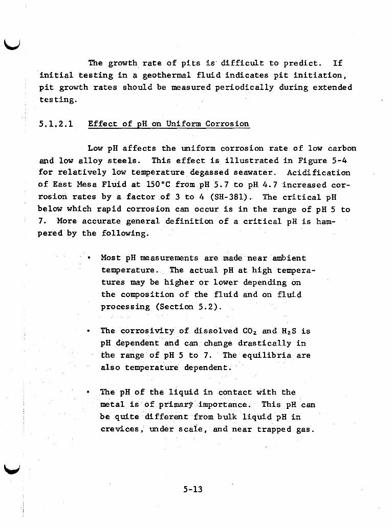
The growth rate of p i t s i s d i f f i c u l t t o predict . I f i n i t i a l t e s t i n g i n a geothermal f l u i d indicates p i t i n i t i a t i o n , p i t growth rates should be measured per iodical ly during extended t e s t ing .
5.1.2.1 Effect of p H on Uniform Corrosion
Low pH a f fec t s the uniform corrosion r a t e of low carbon and low a l loy steels. This e f f e c t i s i l l u s t r a t e d i n Figure 5-4 f o r r e l a t i v e l y low temperature degassed seawater. Acidification of E a s t Mesa Fluid at 150°C from pH 5.7 t o pH 4.7 increased cor- rosion rates by a fac tor of 3 t o 4 (SH-381). The c r i t i c a l pH below which rapid corrosion can occur i s i n the range of pH 5 t o 7. More accurate general def in i t ion of a c r i t i c a l pH i s ham- pered by the following.
Most pH measurements are made near ambient temperature. The actual pH a t high tempera- tures may be higher o r lower depending on the composition of the f l u i d and on f l u i d processing (Section 5.2).
0
The cor ros iv i ty of dissolved C02 and HZS i s pH dependent and can change d ras t i ca l ly i n the range of pH 5 t o 7. The e q u i l i b r i a are a l so temperature dependent.
The pH of the l i q u i d i n contact with the metal i s of primary importance. This pH can be qui te d i f fe ren t from bulk l i qu id pH i n crevices , under s c a l e , and near trapped gas.
5-13
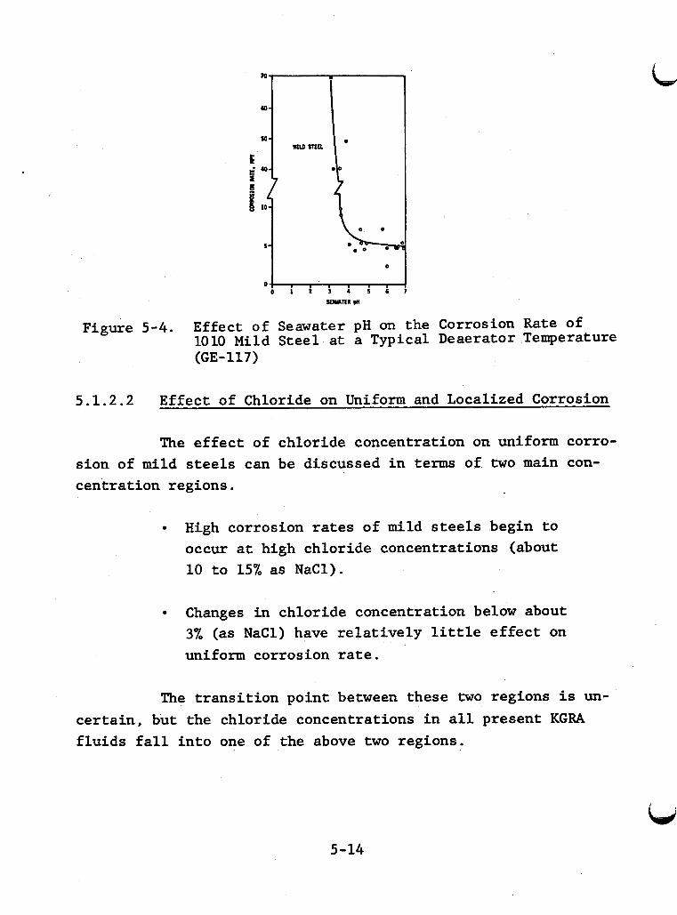
Figure 5-4. Effect of Seawater pH on the Corrosion Rate of 1010 Mild Steel at a Typical Deaerator Temperature (GE- 11 7)
5.1.2.2 Effect of Chloride on Uniform and Localized Corrosion
The e f f e c t of chloride concentration on uniform corro- sion of mild s t e e l s can be discussed i n terms of two main con- centrat ion regions.
High corrosion r a t e s of mild steels begin t o occur a t high chloride concentrations (about 10 t o 15% as NaC1).
, Changes i n chloride concentration below about 3% (as N a C 1 ) have r e l a t ive ly l i t t l e e f f e c t on uniform corrosion r a t e .
The t r ans i t i on point between these two regions i s un- ce r t a in , but the chloride concentrations i n a l l present KGRA f lu ids f a l l i n to one of the above two regions.
5-14
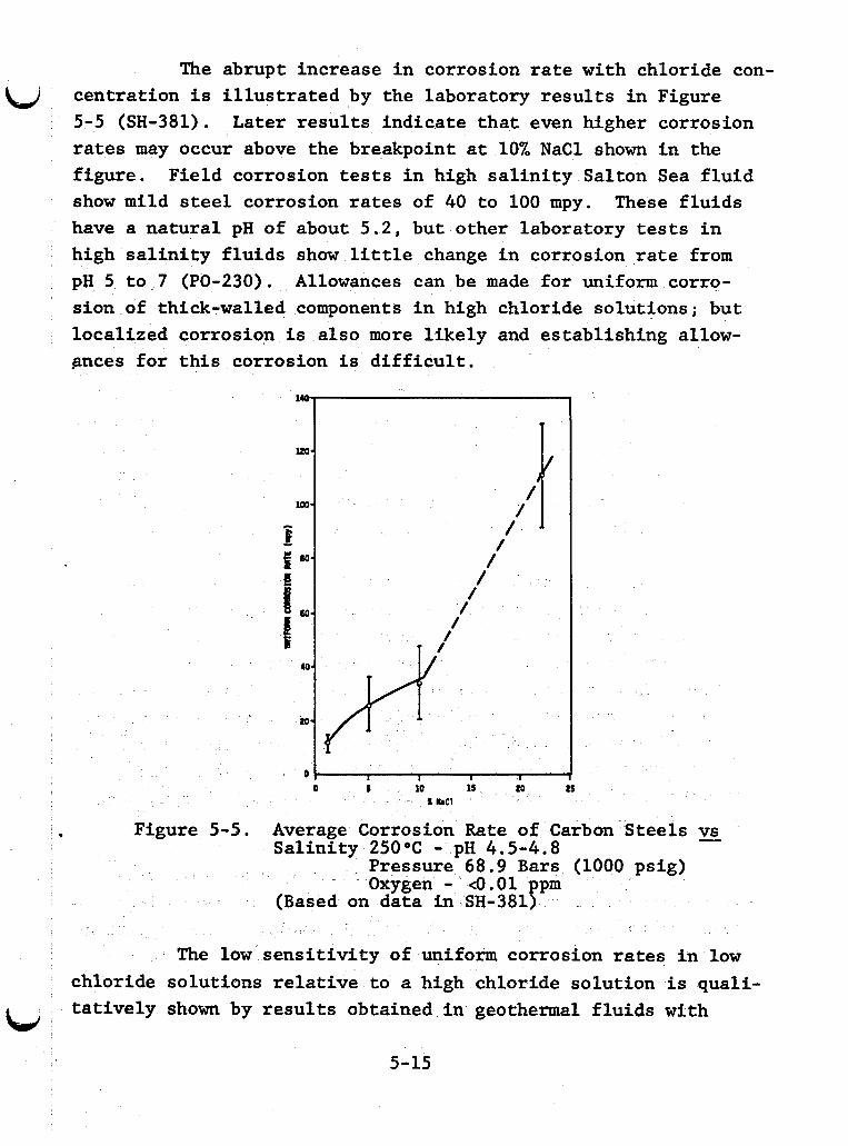
The abrupt increase in corrosion rate with chloride con-
(,J centration is illustrated by the laboratory results in Figure 5-5 (SH-381). Later results indicate that even higher corrosion rates may occur above the breakpoint at 10% NaCl shown in the figure. Field corrosion tests in high salinity Salton Sea fluid show mild steel corrosion rates of 40 to 100 mpy. have a natural pH of about 5.2, but other laboratory tests in high salinity fluids show little change in corrosion rate from pH 5 to 7 (PO-230). Allowances can be made for uniform corro- sion of thick-walled components in high chloride solutions; but localized corrosion is also more likely and establishing allow- gmces for this corrosion is difficult.
These fluids
. Figure 5 - 5 . Average Corrosion Rate of Carbon Steels Salinity 25OOC - pH 4.5-4.8
Pressure 6 8 . 9 Bars (1000 psig) Oxygen - 4.01 ppm
(Based on data in SH-381)
vs -
The low sensitivity of uniform corrosion rates in low chloride solutions relative to a high chloride solution is quali- tatively shown by results obtained in geothermal fluids with bi
5-15
i
d i f f e ren t chloride concentrations (Table 5-2). This trend i s sup- ported by laboratory s tudies a t lower temperatures with other var iables held constant (CH-A-453).
A t high pH, chloride concentration i s more cr i t ical t o p i t t i n g and crevice corrosion than t o uniform corrosion. Chlor- i de effects on p i t i n i t i a t i o n can be described by an experimentally measured p i t t i n g po ten t i a l . P i t t i n g is possible i f the electrode po ten t i a l of a metal exceeds the p i t t i n g poten t ia l . both the corrosion po ten t i a l and the p i t t i n g po ten t i a l of a m e t a l must be known t o make predict ions. es tabl ished f o r measuring p i t t i n g po ten t i a l s , and reported values vary with experimental techniques. sen ts a conservative estimate and should be used a t this t i m e .
Therefore,
No standard method has been
The most active value repre-
This value i s of ten the "protection poten t ia l . " value found by a metal sc ra tch technique can a l so be used.
An equivalent
Although these techniques have promise f o r faci l i ta- t i n g future t e s t i n g , present r e s u l t s are too scarce t o do more than i l lustrate trends. While general trends a re probably appli- cable, crevice corrosion may be i n i t i a t e d more readi ly than p i t t i n g . Most present techniques are less applicable t o crevice corrosion. Localized corrosion e i t h e r under scale o r a t breaks i n scale cannot be predicted from these measurements. P i t growth rate may be proportional t o the amount by which the corrosion po ten t i a l exceeds the p i t t i n g po ten t i a l , but t h i s has received l i t t l e study.
Variation of corrosion and p i t t i n g po ten t i a l s with chloride concentration a t 25°C i s i l l u s t r a t e d i n Figure 5-6. According t o t h i s , steels should be r e l a t i v e l y immune t o p i t t i n g i n oxygen-free chloride solut ions a t 25°C s ince the corrosion po ten t i a l i s more active (negative) than the p i t t i n g poten t ia l . The difference i s small a t higher chloride concentrations and
L
5-16
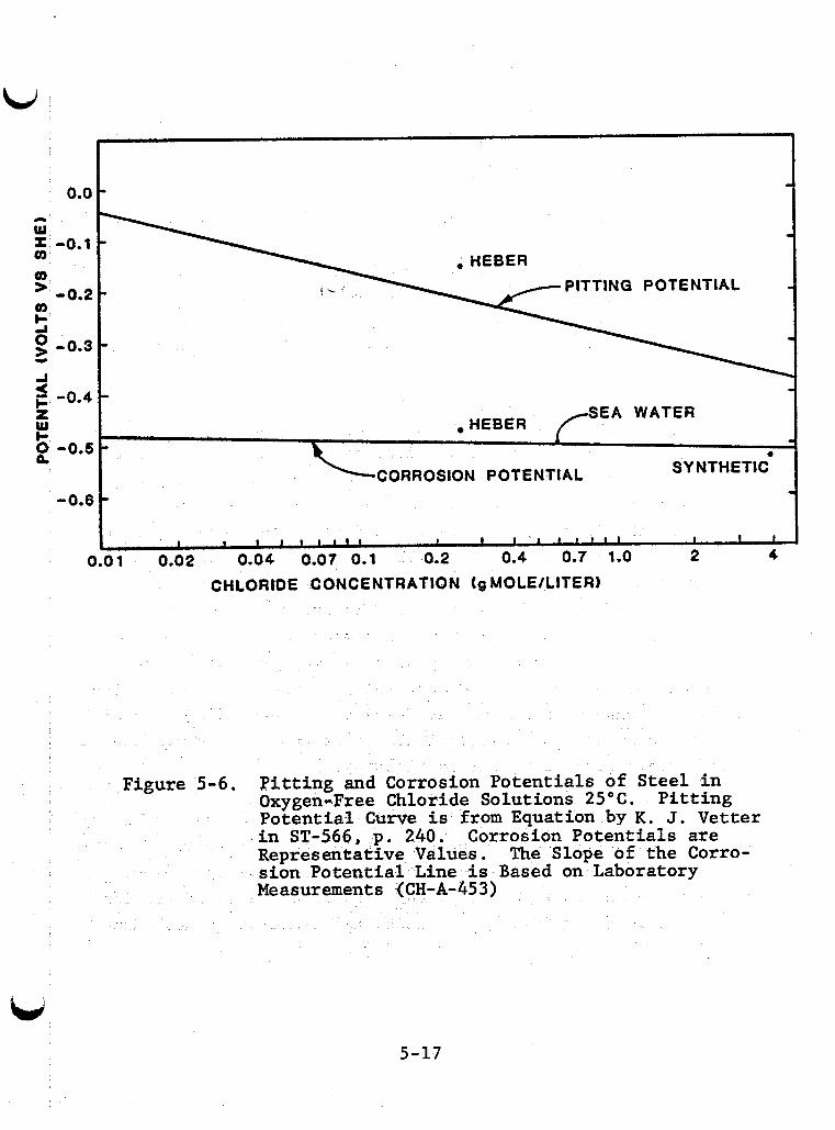
0.0 - - -
PITTING POTENTIAL -0.2 - -
-0.3 - -0.4 - -
SEA WATER HEBER
-0.5 - - e
SY NTHETlC CORROSION POTENTlAL -0.6
- I I I
I I I I f 1 1 I I I I I 1 1 1 1 I I I
0.2 0.4 0.7 1.0 2 4 0.01 0.02 0.04 0.07 0.1
CHLORIDE CONCENTRATION tg MOLE/LITER)
Figure 5 - 6 , Pitting and orrosion Potentials of Steel in Oxygen-Free Chloride Solutions 25OC. Pitting Potential Curve is from Equation by K. J. Vetter .in ST-566, p. 240. Corrosion Potentials are Represerrkative Values. sion Potential Line is Based on Laboratory Measurements (CH-A-453)
The Slope of the Corro-
5-17
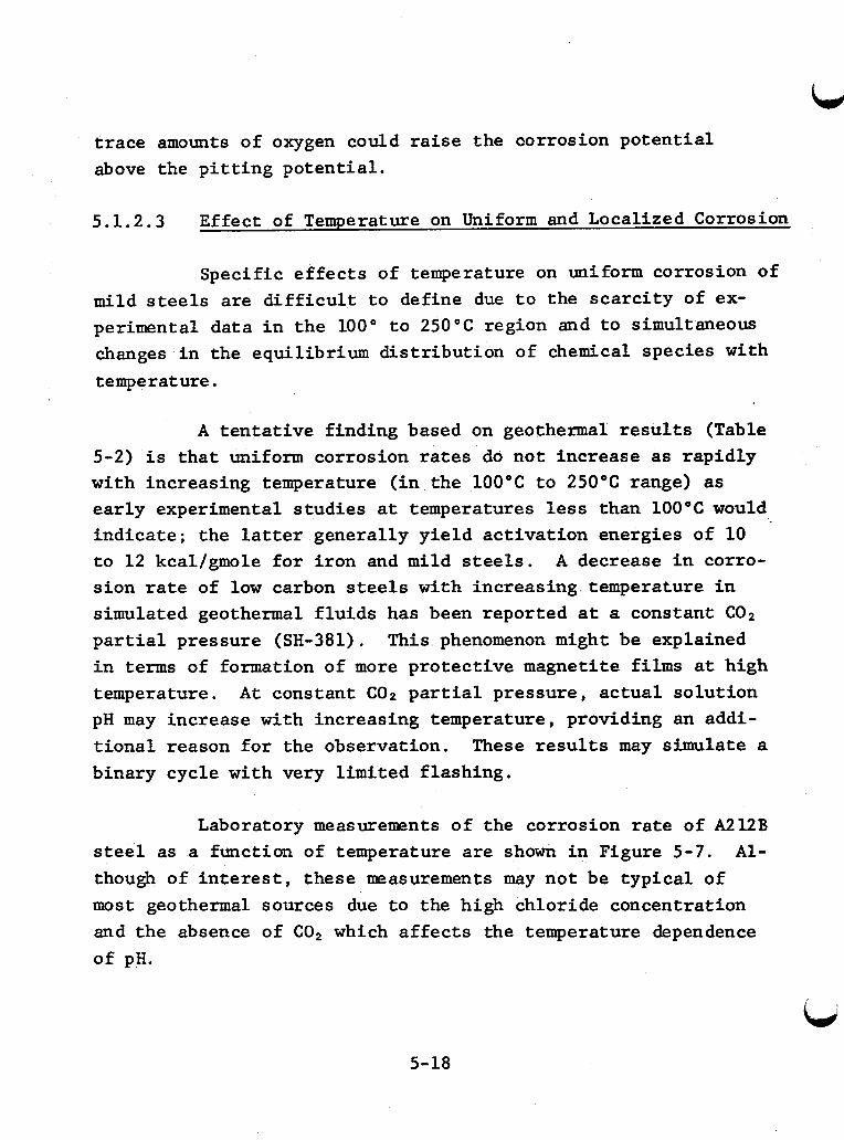
trace amounts of oxygen could raise the oorrosion poten t ia l above the p i t t i n g poten t ia l .
5.1.2.3 Effect of Temperature on Uniform and Localized Corrosion
Specif ic e f f e c t s of temperature on uniform corrosion of mild steels are d i f f i c u l t t o define due t o the sca rc i ty of ex- perimental data i n the 100" t o 250°C region and t o simultaneous changes i n the equilibrium dis t r ibu t ion of chemical species with temperature.
A t en t a t ive finding based on geothermal r e s u l t s (Table 5-2) i s t h a t uniform corrosion rates do not increase as rapidly with increasing temperature (in the 100°C t o 250°C range) as ea r ly experimental s tud ies a t temperatures less than 100°C would ind ica te ; the l a t t e r generally y i e ld ac t iva t ion energies of 10 t o 1 2 kcal/gmole f o r i ron and mild steels. A decrease i n corro- s ion rate of low carbon steels with increasing temperature i n simulated geothermal f l u i d s has been reported a t a constant COP par t ia l pressure (SH-381). This phenomenon might be explained i n terms of formation of more protect ive magnetite f i l m s a t high temperature. A t constant CO2 p a r t i a l pressure, ac tua l so lu t ion pH may increase with increasing temperature, providing an addi- t i o n a l reason f o r the observation. binary cycle with very l imited f lashing.
These r e s u l t s may simulate a
Laboratory measurements of the corrosion rate of A212B steel as a function of temperature are shown i n Figure 5-7. A l - though of i n t e r e s t , these masurements may no t be typ ica l of most geothermal sources due t o the high chloride concentration and the absence of COP which a f f e c t s the temperature dependence of pH.
5-18
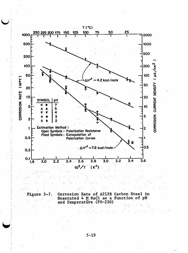
T ('a 50 25
I l l I I I I I I 2000 250225200175 150 125 100 75 io00
'a\* \* "1.
AIooo
0 .t I I I I I I I I 1 1.8 2.0 2.2 2.4 2.6 2.8 3.0 3.2 3.4 3.6
io3/1 ( ~ 9
Ffguxe 5-7, Corrosion Rate of A212B Carbon Steel in Deaerated 4 M NaCl as a Function of pH and Temperatcre (PO-230)
5-19
Although l i t t l e data are avai lable , var ia t ions i n temp- e ra ture may have as great an influence on p i t t i n g as changes i n chloride concentration. Figure 5-8 shows the e f f e c t of tempera- tu re on the p i t t i n g and corrosion poten t ia l s i n a geothermal f lu id . Increasing the temperature d ra s t i ca l ly a f f ec t s the p i t - t i n g poten t ia l but the corrosion poten t ia l remains r e l a t ive ly constant. P i t t i n g increases as the temperature increases . The end points i n Figure 5-8 a t 25°C and 200°C are average values measured i n Heber f l u i d (SY-028). The l i n e a r re la t ionships and ranges shown are assumptions. In deaerated seawater the corrosion poten t ia l increases above about 120°C (SM-A-191). In r e l a t ive ly alkal ine low-chloride solut ions the p i t t i n g poten t ia l may go through a minimum and then increase (become more posi- t i ve ) a t high temperature (ST-566, p. 415).
In s p i t e of the v a r i a b i l i t y noted, the r e s u l t s show t h a t temperature can have a substant ia l e f f e c t on suscep t ib i l i t y t o local ized corrosion.
5.1.2.4 Effect of Other Key Species on Uniform, P i t t i n g , and Crevice Corrosion of Low Alloy Steels
+ The key species considered are H z S , H 2 C 0 3 , NHb , and SO4 . portance i n condensate streams than i n high-temperature sa l ine f lu ids because t h e i r e f f ec t s a r e not masked by chlor ide and be- cause they control pH. Sulfate becomes important only i n those geothermal f l u i d s which have low chlor ide concentrations. Small amounts of oxygen leaked i n t o a geothermal system produce more local ized corrosion than the normal environmental fac tors d i s - cussed. pressure equipment and during shutdown.
- - The f i r s t three species are of r e l a t i v e l y grea te r i m -
This i s primarily a design and operation problem i n low-
5-20
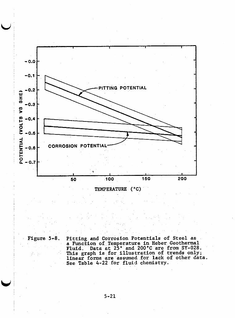
I
U
TEMPERATURE ("C)
Fiwre 5-8, Pitting and Corrosion Potentials of Steel as a Function of Temperature in Heber Geothermal Fluid. Data at 25" and 200°C are from SY-028. This graph is for illustration of trends only; linear forms are assumed for lack of other data. See Table 4-22 for f l u i d chemistry.
5-21
i
H,S - Hydrogen su l f ide i n acidic media can great ly accelerate s t e e l corrosion (MA-A-770, IO-A-21). An i ron su l f ide layer can form on s t e e l s i n the presence of H 2 S , but it of fers no r ea l protection against uniform corrosion. layer flakes o f f , the exposed s t e e l i s subject t o local ized cor- rosion accelerated by galvanic coupling t o the cathodic i ron su l f ide layer . The exposed area may also become loca l ly ac id ic allowing increased H 2 S a t tack. Crevice o r p i t t i n g corrosion i n i t i a t e d by other means may be accelerated by H 2 S which stimu- l a t e s the anodic dissolut ion react ion.
I f par t of the
Cop - Dissolved COP i nd i r ec t ly a f f ec t s corrosion by the buffer ing action of the aqueous species H2CO3, HC03 , and COB . Release of COP during f lashing increases the pH of the f lashed f lu id . Maintaining CO2 pressure while cooling geother- mal f lu ids may decrease pH due t o the temperature dependence of the equilibrium constants. In mildly ac id ic solut ions (pH about 3 t o 5 ) , H2CO3 accelerates the uniform corrosion of mild s t e e l s . Results obtained i n 1% N a C 1 , 0.05 t o 1 .0 a t m C 0 2 up t o 80°C in- dicate tha t t h i s e f f e c t i s due t o accelerat ion of the cathodic (hydrogen evolution) react ion (DE-A-315). Therefore, H2CO3 should not have as adverse an e f f e c t on local ized corrosion rates as H 2 S , which stimulates the anodic (metal dissolut ion) react ion.
- - -
& - Flashed ammonia absorbed i n condensate tends t o neut ra l ize the ac id i ty produced by C02 and H2S, but the ac id ic species are present i n much larger amounts than N H 3 i n most geo- thermal sources. Limited seawater desal inat ion tests showed t h a t the uniform corrosion r a t e of mild s t e e l s increased approximately 65% when 15 ppm N H 3 ( in solut ion) w a s added as ammonia gas (GE-117).
5-22
- SOb” - When the chloride ion concentration i s low, su l -
Sulfate i s much l e s s aggressive than chlor ide i n f a t e becomes the main aggressive ion affect ing uniform corrosion of mild steels. promoting p i t t i n g o r crevice corrosion.
5.1.2.5 Effect of Low Alloy Additions on General Corrosion
In moderate chloride and pH systems, the uniform corro- s ion r a t e s of low a l loy s t e e l s are somewhat lower than low car- bon steels, but the absolute difference i s usually small. P i t - t i n g and crevice corrosion a t tack i s s imi la r t o mild s t e e l s and sometimes more severe fo r low al loys. High-strength low al loy steels may be more suscept ible t o su l f ide s t r e s s cracking or stress corrosion cracking.
Ident i f ica t ion of r e s i s t an t low al loy s t e e l s may be necessary for u t i l i z a t i o n of high chlor ide, low pH geothermal f lu ids due t o the high corrosion r a t e s of p la in s t e e l s ; and crevice corrosion of low a l l o y s t e e l s i n these environments are major concerns. Lawrence Livermore Laboratory.
P i t t i n g
Further t e s t ing i s being conducted by
The l i m i t e d success i n moderate salinity-pH f luids should not preclude fu r the r t e s t i n g of low a l loy steels. term tests i n a seawater b o i l e r at about 200°C showed t h a t s t e e l s containing 0.2% t o 0.3% copper hadt lower p i t t i n g rates than p la in s t e e l s (BU-A-307). Since l i t t l e i p known about long term p i t t i n g rates i n geothermal f l u i d s , comparative t e s t i n g of plain carbon and copper o r other low a l loy s t e e l fo r extended periods is of i n t e r e s t .
Long
Extensive seawater desal inat ion t e s t i n g of low al loy steels showed t h a t they were seldom worth the addi t ional cost
5-23
(GE-117). ve loc i t i e s . success, but more extensive t e s t i n g i s desirable .
A possible exception w a s Cor-Ten steel a t high f l u i d This a l loy w a s t e s t ed a t Raft River with l imited
5.1.3 Stress Corrosion Cracking of Low Alloy Steels
Stress corrosion cracking of l o w a l loy steels i n H2S-free chloride solut ions has been observed. This corrosion should not be a major problem i n the usual range of geothermal environments, but i n - s i t u cracking tests should be conducted. It could be a more severe problem i n ac id i f i ed streams (BA-556, HU-200). See Table 5-3 l e f t column f o r cha rac t e r i s t i c s of SCC.
5.1.4 Sulfide Stress Cracking of Low and Middle Alloy Stee ls
Sulfide stress cracking i s the b r i t t l e f a i l u r e of hard, high s t rength al loys when they are exposed under stress t o en- vironments containing even small amounts of H2S i n an aqueous phase. a general o r l oca l corrosion standpoint. catastrophic , and without warning. There i s l i t t l e o r no evi- dence of metal loss . t i cs of SCC.
Often these envirmments are not pa r t i cu la r ly severe from The f a i l u r e i s sudden,
See Table 5-3 r i g h t column f o r character is-
Sulfide stress cracking (SSC) has been a problem a t Wairakei, N.Z. (FO-120, 34-160, MA-682, FO-119), and Cerro Pr ie to , Mexico (GE-119). It places d e f i n i t e r e s t r i c t i o n s on materials and design f o r any geothermal resource containing HPS. These l imi ta t ions are the r e s u l t of a complex in t e rac t ion of a number of fac tors involving both the environment and the mate- r i a l . temperature, decreasing stress, decreasing y i e l d s t rength , de- creasing H2S concentration, and increasing pH. The e f f e c t s of
Resistance t o SSC generally increases with increasing
5-24
i
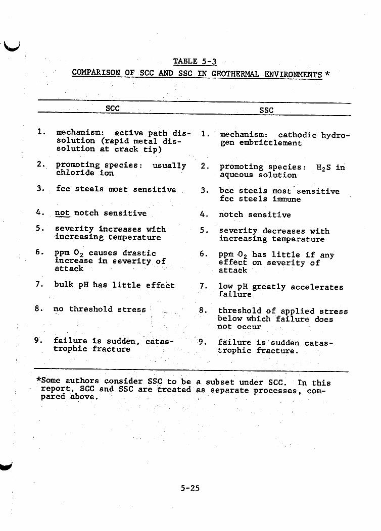
!
TABLE 5-3 COMPARISON OF SCC AND SSC IN GEOTHERMAL ENVIRONMENTS *
SCC ssc
1. mechanism: active path dis- 1. mechanism: cathodic hydro- solution (rapid metal dis- solution at crack tip)
gen embrittlement
2. promoting species : usually 2. promoting species : H2S in
3. fcc steels most sensitive 3. bcc steels most sensitive
chloride ion aqueous solution
fcc steels immune 4. not notch sensitive 5 . severity increases with
increasing temperature
4. notch sensitive
5. severity decreases with increasing temperature
6. ppm 0 , causes drastic 6. ppm 10, has little if any increase in severity of attack attaek effect on severity of
7. bulk pH has little effect 7. low pH greatly accelerates failure
8. no threshold stress 8. threshold of applied stress below which failure does , not occur
9 . failure is sudden, 9 . failure is sudden catas- trophic fracture trophic fracture.
*Some authors consider SSC to be a subset under SCC. In this report, SCC and SSC are treated as separate processes, com- pared above.
5-25
H 2 S concentration, pH, stress, and y i e ld s t rength are interdepen- dent and more s igni f icant than other fac tors such as microstructure and a l loy composition. f irst . Then discussion of the in te rac t ion of these fac tors i s
A discussion of these f ac to r s i s presented
given, followed by comments on other less s ign i f i can t fac tors .
5.1.4.1 Effect of H2S Concentration
The f a i l u r e (cracking) of s t ressed materials i n high H2S environments (above 15-30 ppm) occurs i n days o r not a t a l l . A t concentrations less than 3 ppm, considerably longer t i m e s t o f a i l y r e are observed, and the incubation t i m e may approach the service l i f e of the m e t a l (HU-199, HU-200). Concentrations of H2S as low as 20 ppb accelerate hydrogen en t ry i n t o s teel (HU-A-233). Concentrations less than 0.1 ppm have caused f a i l u r e i n long-term tests.
5.1.4.2 Effect of Stress and Yield Strength (Hardness)
Sulfide stress cracking i s stress dependent and the t o t a l s t r e s s t o which the s t e e l is subjected must be considered, including applied t e n s i l e s t r e s s , res idual t e n s i l e stresses re- s u l t i n g from phase transformation during o r after heat treatment, thermal stress, and cold deformation during fabr ica t ion and ser- vice (VO-067, NA-383, BA-550, HU-200). Even 1% cold work can lower the threshold stress about 30% (BA-563). Cold worked par ts should be heat t r ea t ed t o relieve res idua l stress. A notch grea t ly reduces threshold stress. Threshold stress i s the grea tes t applied stress which does not cause SSC failures. Notches g rea t ly increase the effect of applied stress.
5-26
L/’ Yield s t rength (YS) and microstructure are the most
important mater ia l factors i n SSC. i s the standard c r i t e r ion f o r SSC suscept ib i l i ty . stress decreases as the YS of the s t e e l increases.
Yield s t rength o r hardness The threshold
5.1.4.3 Enteraction of H2S Concentration, S t ress , and Yield Strength
The NACE starrdard fo r sour service i s 90-100 k s i y i e ld s t rength, o r Rc 22. This i s based on performance of steels s t ressed t o 100% YS i n NACE solut ion [5% NaC1, 0.5% a c e t i c acid sa tura ted with H 2 S ] (NA-423).
The actual l imitat ions on usable hardness are a com- p lex in te rac t ion of y ie ld s t rength , applied stress, tempera- tu re and concentration of H2S: of l imi t ing applied stress on usable hardness.
Figure 5-9 shows the e f f ec t
While a given s t e e l may be u t i l i z e d a t much greater y i e ld s t rength and hardness ( ~ 1 2 8 k s i , Rc 30) i f s t r e s ses a re l imited t o 60% of y i e ld , calculat ion shows t h a t the point of maximum re turn on usable s t rength has been passed (HU-200).
he increase i n usable hardness with decre
5.1.4.4 Effect of Microstructure and Composition
Strength and h ss are inadequate fo r defining sus- c e p t i b i l i t y t o SSC (BO-256). resis tance of s t e e l s with the same hardness, while composition
Microstructure a f f ec t s the SSC
b d
5-27
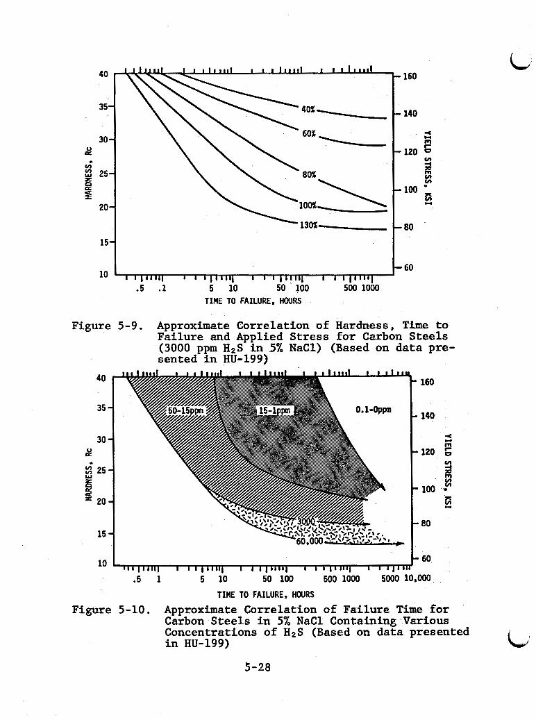
40
35.
30 4
8 .)
v)
25. a p:
9 20.
15.
10 - 60
I I I I l l 1 I I I 1 1 1 1 1 1 I I I 1 1 1 1 1 1 ..
TIME TO FAILURE, HOURS
Figure 5-9. Approximate Correlation of Hardness, Time to Failure and Applied Stress for Carbon Steels (3000 ppm H2S in 5% NaC1) (Based on data pre- sented in HU-199)
40
35
30 8
6
.I
25
20
15
160
140
zs 120 6
9
m
v)
m v) v) 100
80
10 60 I 1 I I 11111 I I I I ""I I 1 I I 1 1 1 1 1 I I I I I I l l 1 I 1 ' 1 '
.5 1 5 10 50 100 500 1000 5000 10~OoO TIME TO FAILURE, HOURS
Figure 5-10. Approximate Correlation of Failure Time for Carbon Steels in 5% NaCl Containing Various Concentrations of H2S (Based on data presented in HU-199)
3-28
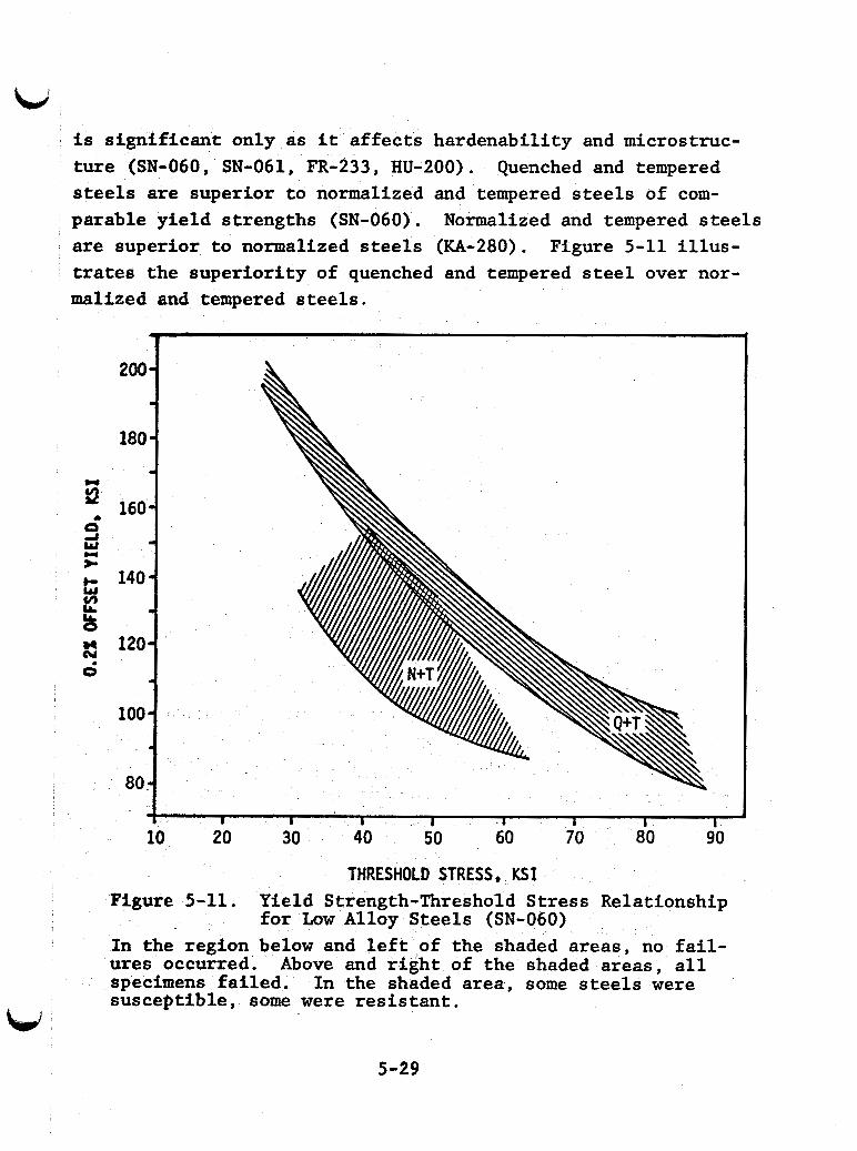
L d i s s ign i f i can t only as i t a f f ec t s hardenabi l i ty and microstruc- t u re (SN-060, SN-061, FR-233, HU-200). Quenched and tempered steels are superior t o normalized and tempered steels of com- parable y ie ld s t rengths (SN-060). Normalized and tempered s t e e l s are superior t o normalized steels (KA-280). Figure 5-11 i l l u s - trates the super ior i ty of quenched and tempered steel over nor- malized and tempered steels.
200 -
iao - .
160 - -
140 *
120-
- 100
. 80 -
W
?
4 I I I I 4 1 I I 10 20 30 40 50 60 70 80 90
THRESHOLD STRESS, KS I Figure 5-11. Yield Strength-Threshold Stress Relationship
f o r Low Alloy Steels (SN-060) In the region below and l e f t of the shaded areas, no f a i l - ures occurred. Above and r i g h t of the shaded areas , a l l specimens f a i l ed . suscept ible , some were r e s i s t a n t .
In the shaded area, some s t e e l s were
5-29
,
L i The most r e s i s t a n t microstructures consis t of r e l a t i v e l y
f ine spheroidized carbides uniformly dispersed i n f e r r i t e . i s typical of martensite tempered a t high temperature. high i n chromium, su l fu r , o r phosphorous are l e s s r e s i s t a n t
This Steels
(SN-061).
The next most r e s i s t a n t microstructures contain coarse . globular and/or laminar carbides (SN-061). Sulfur a l so tends t o
form "str ingers" of inclusions which favor cracking (OH-S-039). Laboratory heats of very low su l fu r steels o r s t e e l s with t r ace lanthanide additions , are very r e s i s t a n t t o SSC (OH-S-039 , SN-06 1, TR-090).
Microstructures containing untempered martensite have the worst res is tance of a l l . pered martensite, especial ly as a network , dras t i ca l ly lower the threshold s t r e s s . Such s t e e l s f a i l at hardnesses far below Rc 22 . These microstructures can occur i n e i t h e r Q and T , o r N and T s t e e l s i f the tempering temperature exceeds the lower c r i t i c a l temperature (austenizing temperature). Additions of nickel and manganese reduce the lower c r i t i c a l temperature, in-
creasing the r i sk of forming untempered martensite. This ac-
counts fo r the poor performance of s t e e l s containing more than one percent nickel (NA-383). Low a l loy s t e e l s containing more than one percent nickel should be t e s t ed careful ly before use. Additions of chromium and molybdenum worsen the s i t u a t i o n because higher tempers are required t o get low enough y ie ld s t rengths .
Even very small t races of untem-
5.1.4.5 Effect of Temperature
The resis tance t o SSC of high s t rength , low al loy s t e e l s increases as temperature increases (TR-090 , TR-S-119 , GR-233), but there i s no temperature above which immunity occurs Table 5-4 shows the e f f e c t of increasing temperature on the useable YS of a n d e r of a l loys. L
5-30
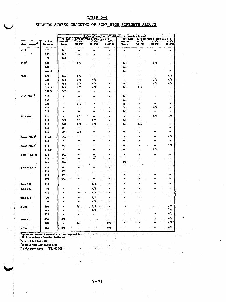
I
TABLE 5-4
SULFIDE STRESS CRACKING OF SOME HIGH STRENGTH ALLOYS ai
5-31
L, 5.1.4.6 Effect of pH
Sulfide stress cracking occurs in acidic solutions. The severity of cracking in solutions below pH 4.5 is relatively constant. Between pH 4.5 and 6, there is a moderate decrease in severity. Resistance to SSC increases rapidly above pH 6, but SSC has been observed at pH 12 (TR-S-119).
5.1.4.7 Effect of Chloride, Moisture, and Oxygen
Chloride ions are not required for SSC (BA-563, TR-S-119), but they increase the severity of SSC in steels containing chrom- ium. Little difference in SSC susceptibility was observed in H2S-saturated chloride-free solutions, 30,000 ppm-chloride solu- tions, and 120,000 ppm-chloride solutions (TR-S-119). Whether chloride affects SSC resistance at low H2S concentrations has not been determined. I
Laboratory tests (SM-A-184, FR-233) and Wairakei field data (MA-682) confirmed that liquid water is required for SSC. Dry steam containing H2S does not appear to be active, but SSC may occur at any location where this steam condenses.
Oxygen has a negligible effect on SSC.
5.1.5 Hydrogen Blistering of Mild Steels
Hydrogen blistering occurs in low strength steels ex- posed to aqueous solutions containing H2S and has been a problem at the Wairakei geothermal plant (MA-682).
In short-term laboratory tests, H2S partial pressures of about 0.02 psia (~60 ppm in solution) were required for hy- drogen blistering of iron (GR-A-330). In long-term tests
5-32
(greater than 200 days) of cold rolled 1036 steel, 1.0 ppm HnS in solution caused blistering while 0.1 ppm did not (HU-200).
Voids are required for blistering, and "killed" (void- free) steels resist blistering. Though not necessarily subject t o blistering, voids in welds may accumulate molecular hydrogen and burst. Stress is not required for hydrogen blistering. The equilibrium pressure of the Ho-H2 trapped in a void is believed to be on the order of l o 5 atmospheres, enough to rupture any known engineering material (FO- 118).
5.2 Stainless Steels
The uniform corrosion rate of most qtainless steels is low in geothermal fluids, but many are subject to the more ser- ious forms of corrosion: pitting, crevice corrosion, stress corrosion cracking, sulfide stress cracking, intergranular corrosion, and corrosion fatigue. Stainless steels have been used in geothermal environments, but care must be taken in their selection and application.
5.2.1 General Guidelines for Use of Stainless Steels
I
Aeration - Many stainless steels which could perform well in oxygen-free geothermal environments can be subject to severe pitting and crevice corrosion in the presence of small quantities of oxygen. used austenitic stainless steels in,high temperature chloride solutions can occur minutes after introducing oxygen in ppm quan- tities or less. This failure is often catastrophic. Other alloys are more resistant. Pits, crevice attack, or cracks initiated during upset or plant outage conditions can continue to grow once normal operation is resumed. Special care should be taken during plant commissioning due to the likelihqod of unstable conditions.
Stress corrosion cracking of commonly
5-33
Flow Rate - Stainless steels are more resistant to high velocities than plain and low alloy steels. city flow is more desirable than low flow rates or stagnant con- ditions. Under stagnant conditions, settling of entrained solids or spot deposition of loose scale can lead to crevice corrosion. Stagnant conditions should be avoided, and stainless components should be drained and rinsed during plant shutdown. Resistance to erosion-corrosion is more closely related to general corrosion resistance than hardness of the metal-
Continuous high velo-
Scale - Local concentration cells can develop under porous or cracked scale on stainless steel and lead to crevice corrosion to which stainless steels are susceptible. After an attack is initiated, local increases in acidity and chloride concentration cause intense corrosion.
Welding - Good welding procedures are important to the successful application of stainless steels. intergranular corrosion by welding is discussed in Section 5.2.6. Physically poor welds may have crevices that are susceptible to crevice corrosion. pits close to poor welds.
Sensitization to
Stress corrosion cracking may initiate at
Exterior Surfaces - Measures should be taken to protect the exterior of stainless steel components that are exposed to air. the high oxygen content of air can subject these components to stress corrosion cracking conditions. Flange leaks leading to conditions in which geothermal fluid concentrates and dries under insulation can be dangerous. Non-porous gaskets are re- quired to guard against cracking at flanges.
Leaks and splashes of hot chloride solutions combined with
5-34
3 L,
W
5 . 2 . 2 Corrosion Resistance of Major Classes of Stainless Steels
400 Series F e r r i t i c and Martensit ic Steels - These ma- terials have poor res is tance t o hot geothermal l iquids . t e n s i t i c steels A I S 1 410 and 440, often used as pump s h a f t s , suf fe red deep p i t t i n g and severe crevice corrosion i n Raft River tests (MI-305). Similar materials have been used w i t h more suc- cess i n geothermal steam. The 400 series f e r r i t i c s may be applied i n low chloride systems, but t e s t i n g i s required.
The mar-
Higher Alloy F e r r i t i c S ta in less Steels - The newer f e r - r i t i c a l loys are much less suscept ible t o stress corrosion cracking than the more common aus t en i t i c s . The 26Cr-1Mo a l loy has shown promise i n f i e l d tests a t East Mesa and i n deaerated flowing seawater. The molybdenum content of t h i s a l loy may not be high enough t o withstand crevice corrosion i n sca l ing environments o r i n applications where per iodic aeration i s p o s s i b l e . higher a l loy , high-purity ferri t ics , 29Cr-4Mo and 29Cr-4Mo-2Ni, generally have outstanding res i s tance t o geothermal environments. These materials can be considered for a l l applications where t h e i r mechnical propert ies are acceptable. i ng a l loy normally has s l i g h t l y better res i s tance t o general corrosion, bu t is more susceptible t o stress corrosion cracking than t h e nickel-free alloy..
The
The n icke l contain-
Austeni t ic S ta in less Steels - Suscept ib i l i ty t o stress corrosion cracking may l i m i t the use of a u s t e n i t i c s t a i n l e s s steels i n geothermal l iqu ids (see Section 5.2.4).
Lower a l loy a u s t e n i t i c a l loys are a l so suscept ible t o p i t t i n g and crevice corrosion. resistance; the addition of molybdenum significantly improved resis- tance.
Type 304 generally has the lowest
Type 316 with 2% Mo has much b e t t e r res i s tance t o p i t t i n g
5-35,
and crevice corrosion than Type 304, but it i s suscept ible t o corrosion i n geothermal f l u i d s , especial ly t o crevice corrosion.
1
Type 317 with 4% molybdenum has s ign i f i can t ly b e t t e r \ corrosion resis tance t o local ized corrosion) and SCC than e i t h e r
304 o r 316. Further t e s t i n g of Type 317 i n geothermal f lu ids i s required.
The high a l loy aus t en i t i c s are s ign i f i can t ly more re- s i s t a n t t o local ized corrosion and somewhat more resistant to SCC than the 300 series, but they are not immune from at tack. Members of t h i s c lass include Alloy 20-Cb3 , Allegheny-Ludlum 6 X , and Haynes Alloy 20 mod. should be weighed against t h a t of materials such as the 29Cr-4Mo f e r r i t i c a l loys , titanium a l loys , Inconel 625 and Hastelloys, which may give b e t t e r ove ra l l corrosion performance i n many ap- p l ica t ions .
The e x t r a cost of these materials
2 Cast Stainless Steels - Suscept ib i l i ty of these metals
t o corrosion i s determined primarily by the chemical composition of the al loy. They are usually equivalent t o comparable wrought alloys. Cast a l loys are usually used for pumps and valves which contain numerous locations fo r crevice corrosion.
5.2.3 P i t t i n g and Crevice Corrosion of Stainless Steels
Pktting and crevice corrosion are the main problems fo r s t a i n l e s s steels which a re r e s i s t a n t t o SCC. Crevice corrosion i s of ten the more serious problem since s t a i n l e s s steels are fre- quently used i n complex equipment where crevice a t tack i s more readi ly i n i t i a t e d . While the de ta i led mechanism of i n i t i a t i o n may be d i f f e ren t f o r p i t t i n g and crevice corrosion, environmental e f f e c t s are similar i n geothermal systems.
5-36
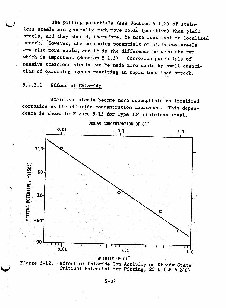
u The pitting potentials (see Section 5.1.2) of stain- less steels are generally much more noble (positive) than plain steels, and they should, therefore, be more resistant to localized attack. are also more noble, and it is the difference between the two which is important (Section 5.1.2). passive stainless steels can be made more noble by small quanti- ties of oxidizing agents resulting in rapid localized attack.
However, the corrosion potentials of stainless steels
Corrosion potentials of
5.2.3.1 Effect of Chloride
Stainless steels become more susceptible to localized
This depen- corrosion as the chloride concentration increases. dence is shown in Figure 5-12 for Type 304 stainless steel.
ACIVIN OF C1- Figure 5-12. Effect of Chloride Ion Activity on Steady-State
Critical Potential fo r Pitting, 25°C (LE-A-248)
5-37
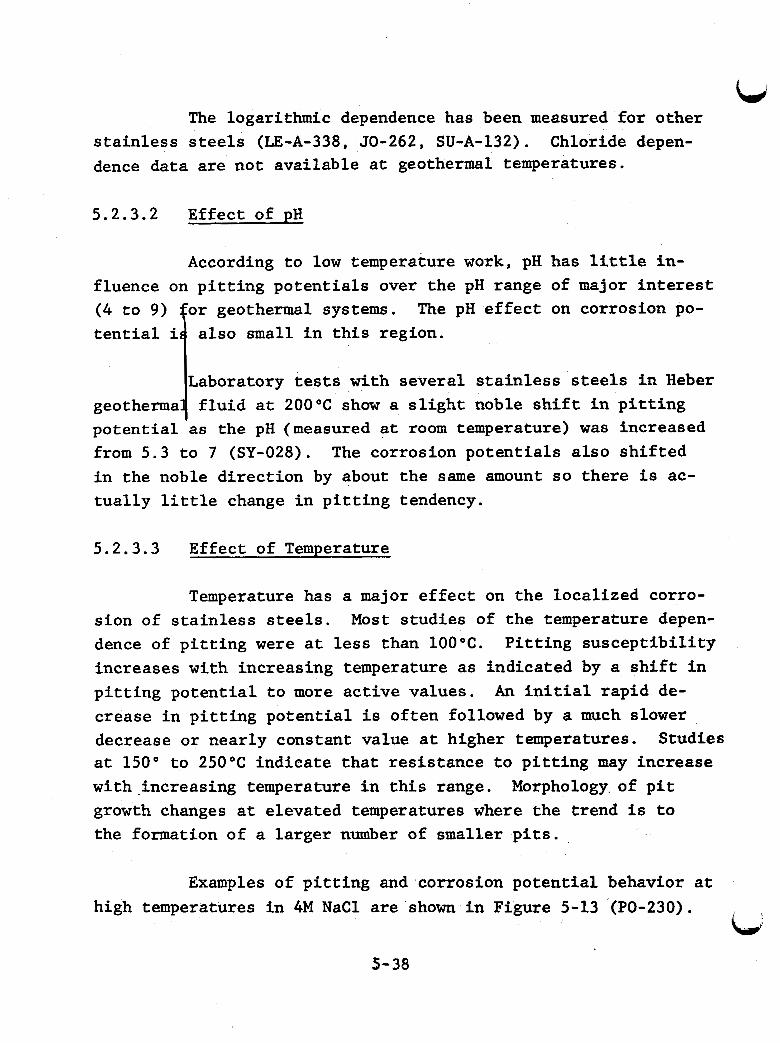
The logarithmic dependence has been measured for other stainless steels (LE-A-338, 50-262, SU-A-132). Chloride depen- dence data are not available at geothermal temperatures.
5.2.3.2 Effect of pH
According to low temperature work, pH has little in-
or geothermal systems. fluence on pitting potentials over the pH range of major interest ( 4 to 9) tential i
The pH effect on corrosion po- also small in this region.
Laboratory tests with several stainless steels in Heber geotherma fluid at 200°C show a slight noble shift in pitting potential as the pH (measured at room temperature) was increased from 5.3 to 7 (SY-028). The corrosion potentials also shifted in the noble direction by about the same amount so there is ac- tually little change in pitting tendency.
1 5.2.3.3 Effect of Temperature
Temperature has a major effect on the localized corro- sion of stainless steels. dence of pitting were at less than 100°C. increases with increasing temperature as indicated by a shift in pitting potential to more active values. An initial rapid de- crease in pitting potential is often followed by a much slower decrease or nearly constant value at higher temperatures. at 150" to 250°C indicate that resistance to pitting may increase with.increasing temperature in this range. Morphology~ of pit growth changes at elevated temperatures where the trend is to the formation of a larger number of smaller pits.
Most studies of the temperature depen- Pitting susceptibility
Studies
Examples of pitting and corrosion potential behavior at high temperatures in 4M NaCl are shown in Figure 5-13 (PO-230).
Ld 5- 38
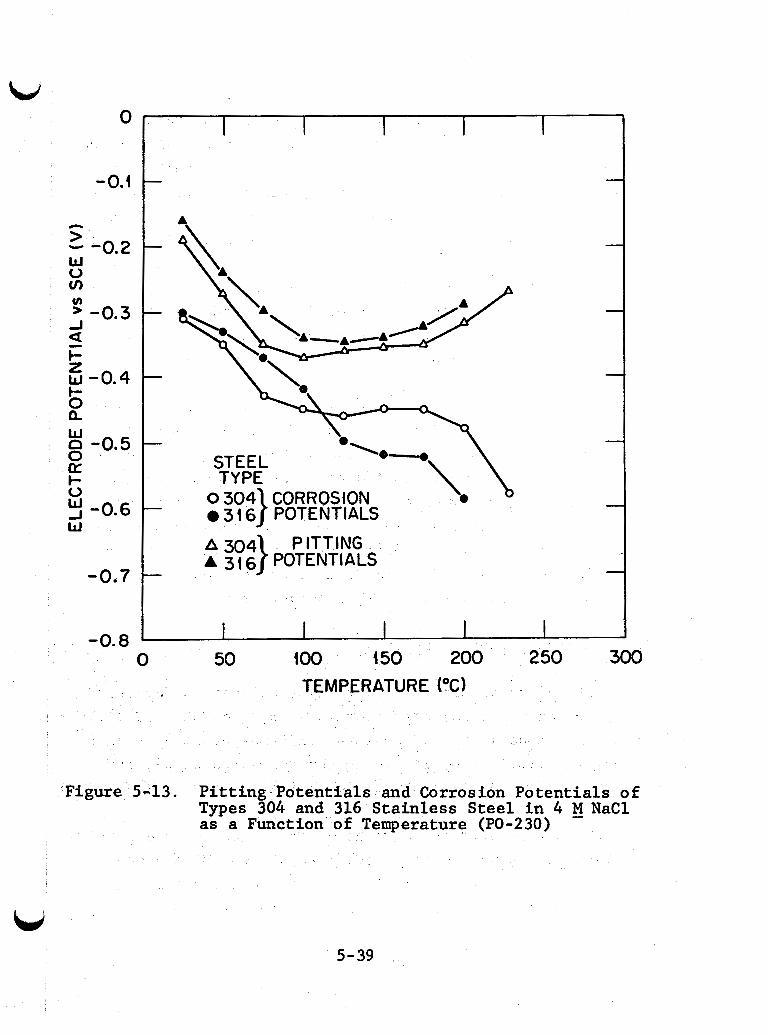
0
-0.4
n > W o v)
- -0.2 v) ’ -0.3 J
I- z w -0.4 I- O Q
E -0.5 0 a I- o
W
a -
5 -0.6
-0.7
-0.8
A
\‘A
A304 PITTING A 3, G } POTENTIALS -
0 50 1 0 0 4 50 200 250 300 TEMPERATURE (0C)
Figure 5-13. Pitting Potentials and Corrosion Potentials of Types 304 and 316 Stainless Steel i n 4 M - NaCl as a Function o emperature (PO-230)
U 5-39
The region near 100°C may ac tua l ly be more dangerous than a t higher temperatures. In t h i s high chloride f l u i d the difference between p i t t i n g and crevice corrosion poten t ia l s i s small f o r Type 304 and Type 316, and p i t t i n g o r espec ia l ly crevice corro- s ion could occur i n the presence of s m a l l amounts of oxidizing agents. S i m i l a r increases occur i n p i t t i n g po ten t i a l f o r metals f o r 100" t o 225°C i n pH 9 solutions with low chloride concentra- t ions (SP-104, ST-566). The decrease i n p i t t i n g tendency a t high temperatures shows tha t materials should be t e s t e d near the temperature a t which they are t o be used even i f i t i s lower than the wellhead temperature.
P i t t i n g k ine t i c s have been s tudied over a l imited t e m - perature range (25"-50"C) f o r 18Cr-12Ni-2Mo-Ti i n 0.1N H 2 S 0 4 + 0.5M N a C l a t constant po ten t ia l s . with increasing temperature (SZ-A-022). Established p i t s grow more slowly a t higher temperatures sYnce the current density within each p i t i s r e l a t ive ly low. S imi l a r e f f e c t s w e r e noted fo r p i t s growing i n ferric chloride solut ion without an exter- n a l l y applied poten t ia l . This is s a i d t o be due t o d i s t r ibu t ion
The number of p i t s increases
of the cathodic current over a la rger number of p i t s .
5.2.3.4 Effects of Other Species
Stainless steels are generally resistant t o corrosive a t tack by contaminated seawater containing H 2 S and NH3 (GE-117). Stagnant conditions should be avoided. H2S may cause p i t t i n g of 316 i n ac id ic solutions by retarding the formation of passive films and causing local ized at tack i n regions of low pH (IJ-A-003).
No direct evidence f o r the effect of COP on the p i t t i n g of s t a i n l e s s steels w a s found i n the l i t e r a t u r e . t r a t ions of H2CO3 i n f a i r l y ac id ic solut ions can catalyze the hydrogen evolution reactior,.
High concen-
L; P i t t i n g of a l loys with p i t t i n g
5-40
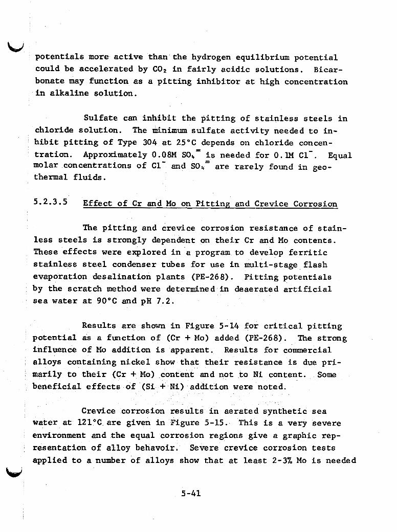
potent ia l s more active than the hydrogen equilibrium potent ia l W
could be accelerated by C02 i n f a i r l y ac id ic solut ions. Bicar- bonate may function as a p i t t i n g inh ib i tor a t high concentration i n a lka l ine solut ion.
Sulfate can i n h i b i t the p i t t i n g of s t a i n l e s s s t e e l s i n chloride solut ion. h i b i t p i t t i n g of Type 304 a t 25OC depends on chloride concen- t r a t ion . Approximately 0.08M SO4 i s needed fo r 0 . lM C1- . Equal molar concentrations of C1- and SOI, are ra re ly found i n geo- thermal f lu ids .
The minimum su l f a t e a c t i v i t y needed t o in-
= =
5.2.3-5 Effect of C r and Mo on P i t t i n g and Crevice Corrosion
The p i t t i n g and crevice corrosion resis tance of s t a in - less steels i s s t rongly dependent on the i r C r and Mo contents. These effects were explored i n a program t o develop f e r r i t i c s t a i n l e s s steel condenser tubes f o r use i n multi-stage f l a sh evaporation desal inat ion plants (PE-268). P i t t i n g potent ia ls by the scratch method were determined i n deaerated a r t i f i c i a l sea water a t 90°C and pH 7.2.
Results are shown i n Figure 5-14 for c r i t i c a l p i t t i n g po ten t i a l as a function of (Cr + Mo) added (PE-268). influence of Mo addi t ion i s apparent. Results f o r commercial a l loys containing n icke l show tha t t h e i r res is tance i s due p r i - marily t o t h e i r ( C r + Mo) content and not to N i content. benef ic ia l e f f e c t s of (S i N i l addition were noted.
The s t rong
Some
Crevice corrosion r e su l t s i n aerated synthe t ic sea water a t 1 2 1 ° C are given i n Figure 5-15. This i s a very severe environment and the equal corrosion regions give a graphic rep- resentat ion of a l loy behavoir. applied t o a number of a l loys show tha t a t l e a s t 2-3% Mo i s needed
Severe crevice corrosion tests
W 5 -41
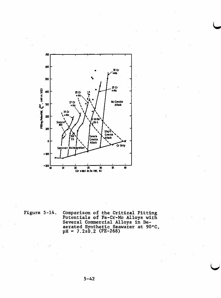
Figure 5-14. Comparison of the Critical Pitting Potentials of Fe-Cr-Mo Alloys with Several Comercial Allovs in De- aerated Synthetic Seawaker at 90°C, pH = 7.2+0.2 (PE-268)
5-42
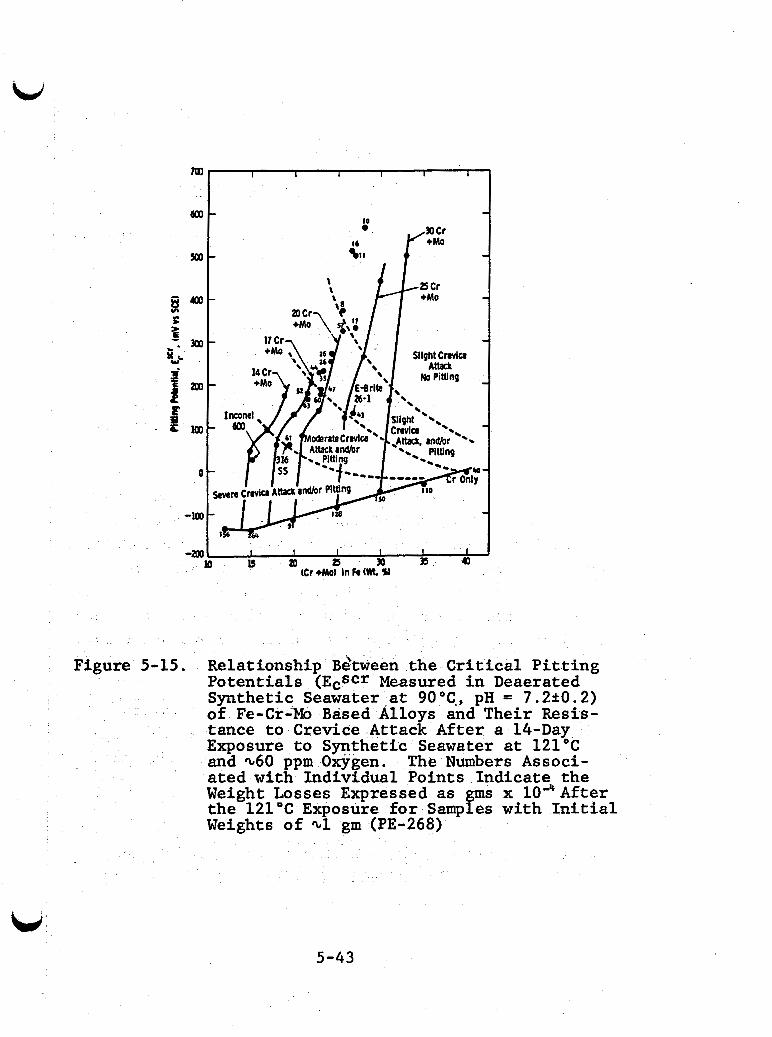
Figure 5-15. Relationship Bstween the C r i t i c a l P i t t i n g Potent ia ls (EcScr Measured i n Deaerated Synthetic Seawater a t 90°C., pH = 7.2k0.2) of Fe-Cr-Mo Based Alloys and Their Resis- tance t o Crevice Attack After a 14-Day Exposure t o Synthetic Seawater a t 1 2 1 ° C and ~ 6 0 ppm Oxygen. The Numbers Associ- ated with Individual Points Indicate the Weight Losses Expressed as gms x 1OaAfter the 1 2 1 ° C Exposure for Samples with I n i t i a l Weights of ~1 gm (PE-268)
I I I I I -mal b ar a 30 35 a tCr +Mot in A Wt. Y
m
5-43
for good crevice corrosion resistance regardless of alloy system (SE-A-133).
5.2.4 Stress Corrosion Cracking of Stainless Steels
Stress corrosion cracking (SCC) promoted by chloride ion is a severe threat in geothermal systems; austenitic steels are the most vulnerable.
Austenitic stainless steels are susceptible to SCC in hot chloride solutions. failure, the use of austenitics in geothermal streams requires careful evaluation. SCC depends on chloride, oxygen, pH, tem- perature, stress, and alloy composition. These factors are dis- cussed below.
Since SCC is a catastrophic type of
Ferritic stainless steels are generally much more re- sistant to SCC than are austenitic stainlesses. Some are sus- ceptible to sulfide stress cracking or cathodic hydrogen embrittle- ment. However, the older alloys, (i.e., AIS1 Types 409, 430, 434, and 4 4 0 ) , are much more susceptible to pitting and crevice corro- sion. New alloys have been developed with much better resistance to pitting and crevice corrosion, but these alloys are not always immune to SCC (NE-207, GE-119, ST-A-570).
The resistance of precipitation hardened stainless steels to SCC in boiling MgC12 varies. for 15 days while 17-4 PH and 15-5 PH failed in less than one day.
PH 13-8 Mo was resistant
5.2.4.1 Effect of Chloride, Oxygen, and pH
It is well established that the severity of SCC in- creases with increasing chloride concentration. chloride concentration may be about 5 ppm (NE-207).
The threshold
5-44
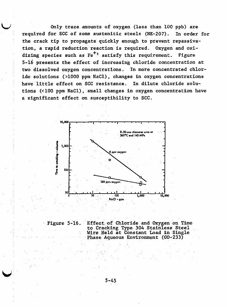
Only trace amounts of oxygen (less than 100 ppb) are required for SCC of some austenitic steels (NE-207). the crack tip to propagate quickly enough to prevent repassiva- tion, a rapid reduction reaction is required. Oxygen and oxi- dizing species such as Fe" satisfy this requirement. 5-16 presents the effect of increasing chloride concentration at two dissolved oxygen concentrations. ide solutions (>lo00 ppm NaCl), changes in oxygen concentrations have little effect on SCC resistance. In dilute chloride solu- tions (<lo0 ppm NaC1) , small changes in oxygen concentration have a significant effect on susceptibility to SCC.
In order for
Figure
In more concentrated chlor-
I ' ' " I ' ' " I ' ' 1 7 .
0.38- diameter wire at . - W ' C ond 115 MPa
10,0oO
- f 1 , O O o ~ E
b
t
% 3 0
loo
10.
5-45
- - - - -
1 l l l l I * c * f a 1 1 1 1 I I l l
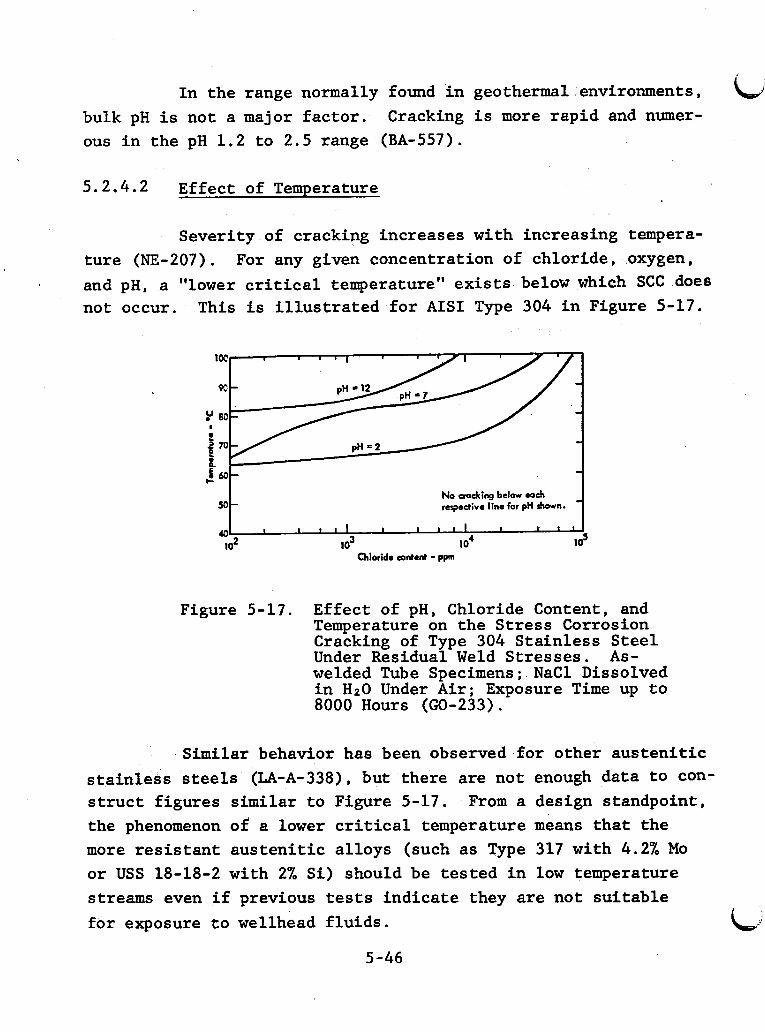
In the range normally found in geothermal environments, Cracking is more rapid and numer- bulk pH is not a major factor.
ous in the pH 1.2 to 2.5 range (EA-557).
5.2.4.2 Effect of Temperature
Severity of crackipg increases with increasing tempera- ture (NE-207). For any given concentration of chloride, oxygen, and pH, a "lower critical temperature" exists below which SCC does not occur. This is illustrated for AIS1 Type 304 in Figure 5-17.
"9 M No cmJting below each respective line for pH shown.
I I I l l I I I I I I I I I
12 40 102 lo3 10' ._
Chloride content - ppn
Figure 5-17. Effect of pH, Chloride Content, and Temperature on the Stress Corrosion Cracking of Type 304 Stainless Steel Under Residual Weld Stresses. As- welded Tube Specimens; NaCl Dissolved in H20 Under Air; Exposure Time up to 8000 Hours (GO-233).
Similar behavior has been observed for other austenitic
From a design standpoint, stainless steels (LA-A-338), but there are not enough data to con- struct figures similar to Figure 5-17. the phenomenon of a lower critical temperature means that the more resistant austenitic alloys (such as Type 317 with 4.2% Mo or USS 18-18-2 with 2% Si) should be tested in low temperature streams even if previous tests indicate they are not suitable for exposure to wellhead fluids.
5-46
L
5.2.4.3 Effect of Stress
Stress is required for SCC, but there is no evident lower critical stress. Time to fracture decreases sharply at stress at or above the yield point (HI-191, H0-348). Total stress is the critical factor. relatively little difficulty because it can be quantified and allowed for. unpredictable. Failures have occurred at zero applied stress (LA-A-338). Aus- tenitic stainless steels should be fully annealed.
Applied stress actually presents
Residual stresses from cold work and welding are Post-welding stress may be near the yield point.
5.2.4.4 Effect of Alloy Composition
Nickel is the constituent having the major effect on susceptibility to SCC in chloride solutions. Immunity from chloride stress cracking is not normally obtained unless the nickel content is less than 1% or greater than 45% (WA-347, LA-A-338). the severe te.st conditions of boiling MgC12, but increasing nickel content above 10% gives some increase in resistance.
All AIS1 austenitics are susceptible to SCC under
of molybdenum improve resistance to SCC. In boiling MgC12, austenitic 18Cr-8Ni-3Mo was more resistant than molybdenum-free 18Cr-8Ni (HI-191). Special Type 317 steel with 4.2% molybdenum is superior to Type 316 in resistance to SCC and local corrosion in aerated and deaerated chloride solu- tions (3000 and 30,000 ppm C1-) over a wide range of pH (LI-A-230). This same alloy was immune 0 SCC for 1464 hours (test duration) in boiling, acidified 25% NaCl (pH 1.5), while Type 304 failed in 10 hours. The increased molybdenum content, and not the slightly higher chromium and nickel content, was responsible for the super- iority (LI-A-230, DU-153).
5-47
Sil icon addition a l so improved resis tance t o SCC; USS 18Cr-18Ni-2Si is 10 t o 100 times more r e s i s t an t than Type 304 i n boi l ing MgC12 and has a good process industry record i n hot chloride systems (LO-A-240). Type 310 containing 1.5% s i l i con showed no SCC and no reaction t o su l f ides i n nonacid chloride solut ions below 450OC. Type 310 tends t o tear and i s d i f f i c u l t t o machine.
Type 314 contains more chromium and nickel than Type 317 and has 2-3% molybdenum and 1.5-3% s i l icon . should be tes ted in geothermal streams.
This a l loy
Additions of small amounts of t i tanium, niobium, tung- s t en , o r manganese may a l so improve resis tance. Additions of const i tuents which favor prec ip i ta t ion of carbides and n i t r i d e s a t the grain boundary decrease resis tance t o SCC.
F e r r i t i c s t a in l e s s s t e e l s containing more than 1% nickel are suscept ible t o SCC i n MgC12 although some r e s i s t cracking i n the wick test and i n boi l ing 20% N a C l (NE-207, ST-A-570, GE-119). The addition of more than 0.5% copper i s detrimental t o f e r r i t i c s t e e l s (GO-233). The 26Cr- lMo, 29Cr-4M0, and 29Cr-4Mo-2Ni al loys depend on l o w i n t e r s t i t i a l concentrations of carbon o r ni t rogen t o r e s i s t SCC i n heat affected zones. 26-1 i s a l so avai lable i n a t i tanium o r niobium s t ab i l i zed form. The 29Cr versions cannot be s t a b i l i z e d i n t h i s way because the amounts of t i tanium o r niobium required adversely a f f ec t d u c t i l i t y and resis tance t o SCC (ST-A-570).
5.2.4.5 Comment on Laboratory Test Methods
The oldest t e s t f o r chloride SCC i s the ‘boiling MgClz t e s t . This i s a severe environment, and it is of ten d i f f i c u l t t o r e l a t e r e su l t s from t h i s t e s t with r e s u l t s from less severe
L
i i t
i
5-48
L) environments (NE-207). The boi l ing L i C l tes t i s usable a t higher pH's , does not form an insoluble hydroxide, has b e t t e r chemical pu r i ty , and cracks Type 304 i n an iden t i ca l manner at similar t i m e s (WI-A-317). The wick tes t (DA-268) i s considered by many t o be the most r e a l i s t i c tes t f o r marine and desalination environments, A d i l u t e N a C l solut ion i s "wicked up" onto an e l e c t r i c a l l y heated U-bend where evaporation concentrated the N a C 1 . solut ions are flashed.
This test is t h o u b t t o be especial ly good where chloride
5.2.5 Intergranular Corrosion of S ta in less Steels
Intergranular corrosion i s severe local ized corrosion a t o r adjacent t o grain boundaries, with l i t t l e o r no at tack on the bodies of the grains. The a l loy d is in tegra tes (grains f a l l out) and/or loses i t s s t rength.
5.2.5.1 Austeni t ic Stainless Steels
Intergranular corrosion occurs i n aus t en i t i c s t a i n l e s s steels when they are sens i t i zed [ i . e . , heated i n the 510-790°C range] (FO-118). The range may extend t o 900°C (CI-A-027). When s t a i n l e s s steels are welded, a zone ca l led the heat affected zone o r HAZ along each s i d e of the weld i s heated i n t o the sen- s i t i z i n g range. HAZ i s i t e of in te rgranular a t t ack , often ca l led weld decay.
tergranular corrosion can be control led i n three ways. F i r s t , the material can be quench-annealed o r solut ion annealed (heated t o high temperature, t y p i c a l l y 1065 "C t o 1120 "C, and water quenched). The quenching i s important because i f the a l loy i s allowed t o cool slowly, the e n t i r e s t ruc tu re w i l l be sens i t ized . S ta in less goods are u s u a l l y s u p p l i e d i n the quench-annealed form. I f they are welded during fabr ica t ion ,
1
I
i I
, , 5-49
LI ; they must be re-treated (FO-118). HAZ intergranular corrosion can be controlled by lowering the carbon content below 0.03%. These alloys do not require quench-annealing after welding and can be welded on-site. picking up carbon when welded. The surfaces around the weld must be kept completely grease and oil free or sensitization will occur. HAZ intergranular attack can also be prevented by the addition of strong carbide formers or stabilizers, to combine with the carbon. ium are used to stabilize stainless steels (FO-118).
j These alloys have a great propensity for
I
i Niobium (or niobium plus tantalum) and titan- i i t
I
!
5.2.5.2 Ferritic Stainless Steels
Ferritic stainless steels are alea subject to inter- granular corrosion and weld decay. The same mechanism, chromium depletion, is responsible.
The range of sensitizing temperatures is not estab- lished, but sensitization of nickel-free ferritic steels begins at about 930°C. Addition of 2% nickel raises the sensitization. temperature to 1040°C. Molybdenum has little effect.
Quenching prevents intergranular corrosion. Weld decay of 1-2% nickel alloys can be prevented by one-hour treatment at 820°C followed by water quenching. Lower nickel alloys require four hours at 820°C (BO-A-323).
Addition oE more than 0.47% titanium to 18Cr-2Mo alloys completely prevents intergranular corrosion in the Strauss test after all sensitizing treatments. 1.2% titanium are embrittled after annealing from 820°C. embrittlement can be removed by water quenching from 1040°C. Additions of 0.'61% niobium prevent intergranular corrosion of post-weld specimens in the Strauss test (BO-A-323).
Alloys containing more than This
5-50
5.2.6 Sulfide Stress Cracking of Stainless Steels
W
Austenitic stainless steels are fcc and are generally considered to be immune to SSC. AISI Types 301, 304, and 310, at fully softened and partially work hardened conditions resisted SSC at 162°C (TR-090).
Martensitic stainless steels are very susceptible to ssc at ambient temperatures (FR-233). AISI Type 410 and Carpenter Custom 450 are susceptible at hardnesses we13 below Rc 22, A 13Cr martensitic steel at the Wairakei geothermal plant resisted SCC below Rc 10 (MA-672). that can be used in sulfide environments at Rc 27 or below
A special 12Cr alloy has been described
(NA-383).
AISI Types 405 and 430 ferritic stainless steels in annealed condition with Rc - <22 are suitable €or H2S service at ambient temperatures (NA-383).
AM-350, AM-355, aqd 18Nimaraging steels offer no im- provement over low alloy steels with regard to SSC resistance, (HU-200). 17-4 PH, 15-5 PH, and PH 13-8Mo are susceptible to SSC at stresses between 30% and 50% of yield (RA-347). A-286 was not susceptible at 98% of yield strength at room temperature. The resistance of A-286 decreases as temperature increases (TR-090). tation hardening steels is not known.
Whether or not this effect is common to all precipi-
5.3 Titanium and Titanium Alloys
Titanium and its alloys have given good results in all but the most extreme environments when tested for geothermal applications. Titanium was used successfully for hydrogen and oil coolers exposed to aerated cooling water/condensate at the
5-51
Cerro Prieto geothermal facility (GE-119). Two other heat ex- changer materials had failed in this environment.
5.3.1 Uniform Corrosion of Titanium
The uniform corrosion rate of titanium and titanium alloys tested in geothermal fluids has been less than 0.3 mpy. The corrosion rates of these materials when exposed to worst case conditions of aerated geothermal fluids have been good with corro- sion rates of less than 0.5 mpy.
Increasing temperature and chloride concentration do not increase uniform corrosion of titanium alloys. seawater desalination plants indicates that fluid velocities of 30 fps have no effect on uniform corrosion. Titanium is also very resistant to impingement and cavitation damage (GE-117).
Experience in
5.3.2 Pitting and Crevice Corrosion of Titanium
No significant local corros$on should occur in environ- ments with less than 10% chloride. Desalination and chemical process industry experience shows that crevice corrosion in tight crevices may be a problem in high-temperature, high-chloride solutions similar to Salton Sea fluid. sional problem.
Pitting may be an occa-
The dominant factors controlling localized corrosion of titanium and its alloys are chloride concentration, pH, and temperature.
5.3.2.1 Effect of Chloride and Temperature
The interaction of chloride concentration and tempera& ture is given in Figure 5-18.
5-52
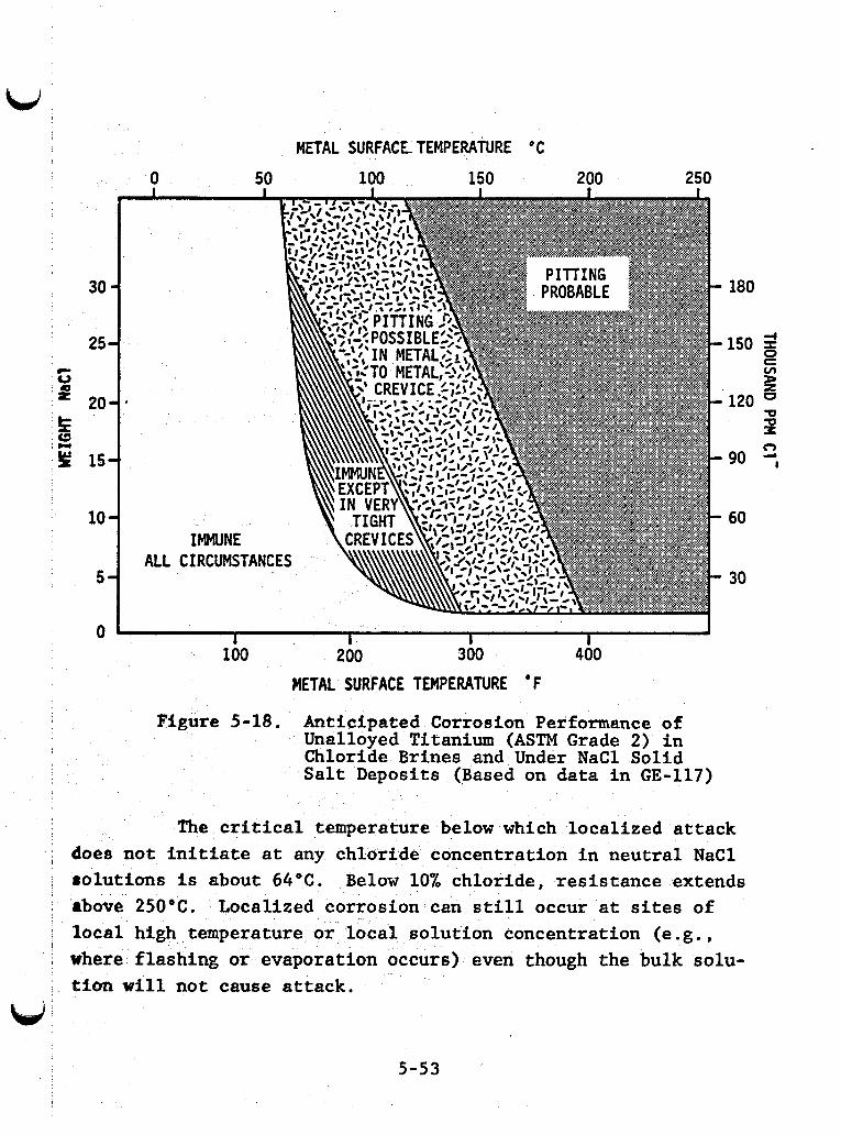
I
u METAL SURFACE TEMPERATURE C
0 50 100 150 200 250
l01 IMMUNE
'i
180
150 z P
s
v)
120 W
90 2,
60
30
1 I I I 100 200 300 400
METAL SURFACE TEMPERATURE ' F
I
Figure 5-18. Anticipated Corrosion Performance of Unalloyed Titanium (ASTM Grade 2) in Chloride Brines and Under NaCl Solid Salt Deposits (Based on data in GE-117)
The critical temperature below which localized attack does not initiate at any chloride concentration in neutral NaCl rolutions is about 64OC. Below 10% chloride, resistance extends above 250OC. Localized corrosion can still occur at sites of local high temperature or local solution concentration (e.g., where flashing or evaporation occurs) even though the bulk solu- tion will not cause attack.
5-53
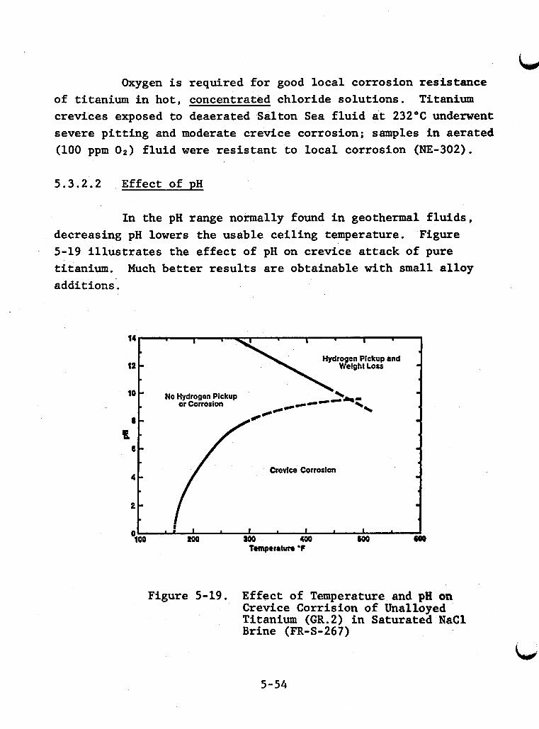
Oxygen is required for good local corrosion resistance of titanium in hot, concentrated chloride solutions. Titanium crevices exposed to deaerated Salton Sea fluid at 232°C underwent severe pitting and moderate crevice corrosion; samples in aerated (100 ppm 0 2 ) fluid were resistant to local corrosion (NE-302).
5.3.2.2 Effect of pH
In the pH range normally found in geothermal fluids, decreasing pH lowers the usable ceiling temperature. Figure 5-19 illustrates the effect of pH on crevice attack of pure titanium. additions.
Much better results are obtainable with small alloy
I
Hydrogen Pickup and 12 -
I
10 No Hydrogen Pickup -
or Corrosion
Crevice Corrosion
8 -
Temperrtun 'F
Figure 5-19. Effect o f Temperature and pH on Crevice Corrision of Unalloyed Titanium (GR.2) in Saturated N a C l Brine (FR-S-267)
5-54
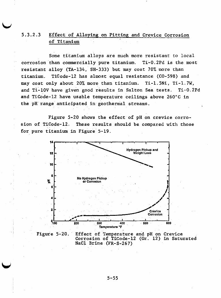
5.3.2.3 Effect of Alloying on Pitting and Crevice Corrosion of Titanium
I
corrosion res is tan t titanium.
Some titanium alloys are much more resistant to local than commercially pure titanium. alloy (TA-134, SH-333) but may cost 70% more than
Ti-0.2Pd is the most
TiCode-12 has almost equal resistance (CO-598) and may cost only about 20% more than titanium. and Ti-1OV have given good results in Salton Sea tests. and TiCode-12 have usable temperature ceilings above 260°C in the pH range anticipated in geothermal streams.
Ti-1.5Ni, Ti-1.7W, Ti-0.2Pd
Figure 5-20 shows the effect of pH on crevice corro- sion of TiCode-12. These results should be compared with those for pure titanium in Figure 5-19.
No Hydrogen Pickup or Corrosion
Figure 5-20. Effect of'Temperature and pH on Crevice Corrosion of TiCode-12 (Gr.. 12) in Saturated NaCl Brine (FR-S-267)
5-55
5.3.3 Galvanic Coupling and Other Precautions
Titanium is cathodic to most other metals in saline environments. If the titanium area is large compared to the other metal to which it is coupled, the second metal may corrode severely.
Since titanium is the cathode in most galvanic couples, hydrogen can be formed on titanium coupled to an active metal. Titanium is capable of absorbing hydrogen and becoming embrittled '(CO-598). brittlement in desalination service (GE-117).
Some Ti-Ni alloys are susceptible to hydrogen em-
Titanium-tube-to-Monel-tubesheet crevices strongly resist crevice corrosion, but this couple has caused pitting of titanium under salt scale at sites some distance from'the cre- vice. crevice attack. susceptible to attack than titanium-to-titanium crevices.
Titanium-to-Type 316 crevices are also resistant to Tight titanium-to-Teflon crevices are much more
Iron particles left in scratches on titanium can ini- tiate pits (CO-598). tubes with ferrous alloy tools.
Care must be taken to avoid scratching the
High-density, powder metallurgy titanium alloys are generally comparable to wrought equivalents. They offer cost advantages for complex shapes. MgCl inclusions in powder metallurgy titanium serve as nucleation sites for pitting. A low magnesium alloy will give better service than one containing a few ppm MgC12 (BO-270).
5-56
\
5.3.4 Stress Corrosion Cracking of Titanium Based Alloys
Commercial titanium alloys are not considered to be susceptible to cracking in 3% NaCl solutions at ambient tempera- tures. However, precracked specimens of many fail rapidly in 3% NaCl solutions. This behavior indicates that the resistance of some titanium alloys is dependent on the integrity of the pro- tective oxide €ilm and not on the intrinsic resistance of the alloy lattice (BO-A-314). SCC should therefore not be a major problem, provided that components are not pre-cracked during fabrication and that the design does not allow excessive vibra- tion of titanium parts.
The susceptibility of precracked titanium alloys to SCC is adversely affected by aluminum, tin, manganese, cobalt, and/or oxygen content. cent aluminum are especially susceptible. niobium, or vanadium reduce or eliminate the. susceptibility to chloride-enhanced propagation of cracks in precracked specimen (BO-A-314). Table 5-5 lists resistant alloys and alloys-which are sensitive in the precracked condition.
Some alloys containing more than 6 per- Additions of molybdenum,
Only chloride, bromide, or iodide ions are effective as cracking agents. Fluoride, hydroxide, sulfide, sulfate, ni- trite, nitrate, perchlorate, cyanide, and thiocyanate have no effect. Different alkali or alkaline earth cations have little effect on cracking (BE-A-501).
Both hydrogen embrittlement and active path dissolution are involved in the mechanism of crack propagation (BO-A-314, MA-705, CO-598).
5-57
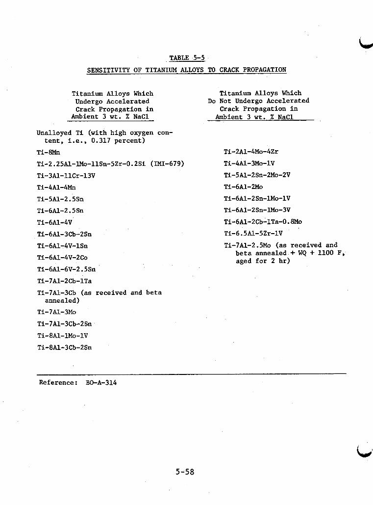
TABLE 5-5
SENSITIVITY OF TITANIUM ALLOYS TO CRACK PROPAGATION
Titanium Alloys Which Undergo Accelerated Crack Propagation in
Ambient 3 wt. % NaCl
Titanium Alloys Which Do Not Undergo Accelerated
Crack Propagation in Ambient 3 wt. % NaCl
Unalloyed Ti (with high oxygen con-
Ti-8Mn Ti-2.25Al-lMo-llSn-5Zr-O.2Si (IMI-679) Ti-3Al-llCr-13V Ti-4Al-4Mn
tent, i.e., 0.317 percent)
Ti-5Al-2.5Sn Ti-6Al-2.5Sn Ti-6Al-4V Ti-6Al-3Cb-2Sn Ti-6A1-4V-lSn Ti-dAl-4V-2Co Ti-6Al-6V-2.5Sn Ti-7A1-2 Cb- 1Ta Ti-7Al-3Cb (as received and beta annealed)
Ti-7Al-3Mo Ti-7Al-3Cb-2Sn Ti-8Al-lMo-lV Ti-8Al-3Cb-2Sn
Ti-2A1-4Mo-4Zr Ti-4Al-3Mo-lV Ti-5Al-2Sn-2Mo-2V Ti-6A1-2M0 Ti-6Al-2Sn-lMo-lV Ti-6A1-2Sn-lMo-3V Ti-6Al-2Cb-lTa-0.8Mo Ti-6.5Al-5Zr-lV Ti-7Al-2.5Mo (as received and
beta annealed + WQ + 1100 F, aged for 2 hr)
Reference: BO-A-314
5-58
5.4 Nickel Based Alloys
High nickel alloys are frequently used to combat severe
Similar alloys corrosion problems. applicable to high temperature geothermal fluids. containing iron in place of molybdenum face competition from the most resistant stainless steels, but may find application where their mechanical properties are desirable. Cupronickels will have limited usefulness in geothermal streams containing even trace quantities of H2S.
The Ni-Cr-Mo alloys appear to be the most
5.4.1 General Corrosion Resistance of Ni-Cr-Mo Alloys
The higher ranked members of this class of alloys such
These two alloys
Effects of alloy composition are complex, but high molyb-
as Inconel 625 and Hastelloy C-276 have given excellent resistance to corrosion in geothermal systems. can normally tolerate very high flow rates and occasional aera- tion. denum content is important for best corrosion resistance. Some pitting and crevice corrosion has been observed for Hastelloy G in both Salton Sea and Raft River fluids. Inconel 600 contains no molybdenum and was attacked at a rate of 10 mpy in 1% NaC1, pH 5, 10 ppm H2S solution at 250°C (SH-381). In the same tests Hastelloy C-276 and Inconel 625 corroded at only 0.2 mpy.
t
5.4.2 Stress Corrosion Cracking of Nickel Based Alloys
Nickel-based alloys contain more than 45% nickel and If interstitial should therefore have good resistance to SCC..
carbon is not kept low (<0.004%) , these molybdenum-bearing nickel based alloys may be susceptible to SCC in heat affected zones from welds (ST-A-563).
5-59
The following alloys were resistant in the unsensitized state to boiling MgC12 for 15 days: Inconel 625, Inconel X-750, Inconel 825, Monel K-500, Hastelloy C, Hastelloy C-276, and Hastelloy C-4 (WA-347, ST-A-563). Other nickel-based alloys may also be resistant to SCC,.
5.4.3 Sulfide Stress Cracking and Hydrogen Embrittlement
Monel (Rb 63) and K-Monel (Rc 37) were completely re- sistant to sulfide stress cracking during the standard NACE test at ambient temperatures (HU-200, VO-067). Monel K-500 (Rc 36) was resistant at 98% YS. Inconel 625 (Rc 20 and 39), Inconel X-750 (Rc 37), and Inconel 718 (Rc 34) were resistant at 98% YS. Hastelloy C-276 (Rc 41) and Hastelloy G (Rc 35) were also re- sistant (WA-347).
Hastelloys G and C-276, and Inconel 625 are susceptible In the presence to hydrogen embrittlement when coupled to steel.
of dissolved oxygen, no H2S is required; but H2S reduced the time-to-failure (KA-A-301). The effect of coupling to steel has not been documented for other nickel-based alloys.
5.4.4 Intergranular Corrosion of Nickel Based Alloys
The mechanism of intergranular corrosion of Hastelloy C, C-4, and C-276 is slightly different than that for austenitic stainless steels. At carbon concentrations greater than 0.004% a molybdenum-rich carbide (M6C) forms in the temperature range 649"C-l204"C, depleting molybdenum in the grain boundaries. The molybdenum depleted zones are attacked by reducing acids (ST-A-563) and 'could be affected by geothermal fluids.
5-60
Copper Based Alloys - 5.5
The use of copper alloys in geothermal fluids is severely limited by the relatively high concentrations of sul- fide found in most sources. sulfide concentration of 0.1 ppm, appears to be an exceptional case. (Monel 400, 70Cu/30Ni, and 9OCu/lONi) was very poor. Dealloying of some copper alloys was observed. However, some nickel-free brasses and bronzes gave acceptable performance (MI-305).
The Raft River -KGRA, with a low
Even in this fluid the performance of copper-nickel alloys
The cracking of some copper-based alloys, especially a brasses, exposed to ammonia or ammonia derivatives is well known under the name "season cracking" (FO-118).
required at the metal surface in significant quantity. adsorbed layer of O2 or a thin oxide film also seems. necessary (BO-A-313, PU-A-068). cracking by ammonia species in the liquid phase of geothermal fluid should be limited to stagnant areas. Ammonia in the steam phase could concentrate in moisture films, posing a considerable hazard.
When cracking
An
is caused by ammonia species, cupric complexes {Cu(NH3)n +2 1 are
Unless: the NH3 or NHs+ level is high,
pH has a considerable effect on SCC of copper-based Cracking does not appear to occur
From pH 4.7 to 7.5 thin tarnish
alloys by ammonia species. at pH <3.9. cracking is transgranular. films form, and the cracking is intergranular. film forms and cracking is again transgranular.
Between 3.9 and 4.7 a red coating is formed and
At pH >7.5, no
The susceptibility of copper-zinc brasses to cracking by ammonia species increases with increasing zinc concentration. In Cu-Ni brasses the susceptibility is maximum at about 10% Ni.
gsit Resistance increases sharply above %30% Ni. The resistance of
5-61
i i
i
Lid Cu-A1 alloys is lowest between 1 and 2% A1 and increases sharply I above %5% A1 (PU-A-068).
SCC of admiralty brass under anodic polarization but in the absence of ammonia has been observed (KA-A-302).
5.6 Applicability of Other Metallic Materials
A number of other metals and alloys may either have important specialized but limited uses in geothermal applica- tions or have not shown promise in geothermal tests. materials are discussed in this section.
These
5.6.1 Cobalt Alloys
Cobalt alloys may find application in services re- quiring high strength combined with resistance to sulfide stress cracking and in services requiring wear resistance.
MP35N resists sulfide stress cracking at high yield strengths and may be useful for well instrumentation cables, pump springs, and other downhole tools. Haynes 25 was resistant to very high velocity acidified Salton Sea fluid during a short- term test (AU-064). No pitting or crevice corrosion of Haynes - 6B, another wear-resistant alloy, was observed in Raft River field tests.
Cobalt-base alloys generally have good resistance to sulfide stress cracking. MP35N (Rc 51), MP159 (Rc 46); Haynes Alloy 25 (Rc 47), were resistant at 89% YS (WA-347). Stellites 1 and 6 were also resistant (FR-233). However, MP35N may be susceptible to sulfide stress cracking when coupled to a more active metal such as iron (TR-090). The effect of galvanic
5-62
coupling on the SSC resistance of other cobalt alloys is not known.
Alloys MP35N and MP159 are resistant to stress corro- sion cracking in boiling MgC1, (WA-347). Data about other cobalt alloys are lacking.
I
5.6.2 Zirconium and TantBlum
Zirconium and tantalum may be considered for severe, hot acid chloride service such as injection nozzles for acidify- ing fluid with hydrochloric acid.
5.6.3 Aluminum Alloys
Aluminum alloys have not shown good resistance in tests conducted in direct c.ontact with geothermal fluids. levels of transition metal ions, especially copper and mercury, greatly increase localized attack of aluminum alloys. These ions are present in most liquid-dominated geothermal fluids.
Low
Rapid pitting of a1 test coupons was observed in condensate and cooling water at Cerro Prieto, Mexico (GE-11.9).
Aluminum alloys are subject to severe attack when gal- vanically coupled to almost any other metal likely to be used in a geothermal plant.
Exterior siding and structural components of aluminum are likely to give adequate service due to the good atmospheric
emissions. are used in new housings at The Geysers power plant.
corrosion behavior of aluminum and resistance to occasional H2S Fluoropolymer-coated aluniinum exterior sliding panels
5-63
5.7 Condensate
The corrosivity of condensate streams depends to a large extent on the following factors:
Efficiency of steam separation and thus the chloride content of the condensate,
Quantity of the flashed noncondensable gases C02, H2S, and NH3 which are absorbed by the condensate,
pH of the condensate resulting from absorp- tion of the above gases,
Aeration or mixing with aerated water.
These factors are interactive. can be tolerated if the condensate is not aerated. the condensate depends primarily on the amount of acidic C02 and H2S absorbed relative to basic NH3. The pH in turn deter- mines the corrosivity of dissolved H2S and CO2 in contact with mild steels. and H2S and the condensate pH will be fairly'low.
Higher chloride concentrations The pH of
For most sources the NH3 is low compared to CO2
Previous sections can be consulted for discussion of effects of pH, H2S, C02, " 3 , and oxygen. have occurred in the condensate systems of several operating geothermal plants (see Appendix A). Although condensate streams have relatively low chloride concentrations, their potential corrosivity should not be underestimated.
Corrosion problems
Even with very efficient steam separation the chloride content of the condensate can be high enough to cause problems.
5-64
For example, assuming 25% flashing of a wellhead liquid con- taining 1% chloride and 0.05% liquid carryover, the condensate would contain about 20 ppm chloride. This is approximately equal to the minimum chloride concentration needed to cause pitting of plain steels at 25°C (SZ-020).
If the condensate is aerated and temperature is greater than 60" to 80"C, stress corrosion cracking of austenitic less steels could occur at this chloride concentration.
stain-
5.8 Steam from Liquid-Dominated Geothermal Sources
Steam from liquid-dominated geothermal fluids has corrosion characteristics of its own, but general corrosivity is dominated by two properties common to the saline fluid and condensate streams.
Carryover of entr ined liquid provides the chloride needed for localized attack. High- velocity impingement of droplets is conducive to localized attack. Efficient steam separa- tion and steam scrubbing are important, but may not preclude attack. For a given steam separation and scrubbing ef f ic iency , corro-
sivity may depend on the chloride content and corrosivity of the liquid stream.
Areas where local condensation may occur are subject to attack by low pH condensate con- taining H2S, C02 and some chloride. Most noteworthy of these locations are the low pressure turbine section, liquid traps and poorly insulated or stagnant parts of steam transfer sections. eliminated by design.
The latter should be
5-65
Steam scrubbing can reduce the number of drops but not the chloride concentration of each drop; little reduction in corrosion rate after steam scrubbing was found. noteworthy that the localized corrosion susceptibility of resistant alloys is similar in Salton Sea wellhead liquid, sep- arated steam, and scrubbed steam.
It is also
5.8.2 Corrosion Fatigue
5.8.1 General Corrosion in Geothermal Steam
Corrosion rates of low alloy steels in steam flow from several geothermal sources are summarized in Table 5-6. Uniform corrosion rates in oxygen-free steam are generally low except in separated Salton Sea steam. rosion rates in this steam is unclear. One possible explanation
essentially the same high chloride concentration as the wellhead liquid. these chloride concentrations in impinging droplets and not just the diluted concentration of the condensate. The low chloride contents quoted for the steam phase may therefore be misleading.
The reason for high cor-.
'may be the entrained liquid. Each entrained liquid drop contains
The metal surfaces in the steam flow are exposed to
Although corrosion fatigue occurs in both steam and liquid media, this failure mode is discussed in this section because turbines operating in geothermal steam are subject to both environments. Turbines are the most important com- ponents in a geothermal plant that will be subject to corrosion fatigue.
Metals under cyclic loading fail at stresses far below those characterizing their normal mechanical properties. When this phenomenon occurs in "inert" environments, (i.e. air),
5-66
I .
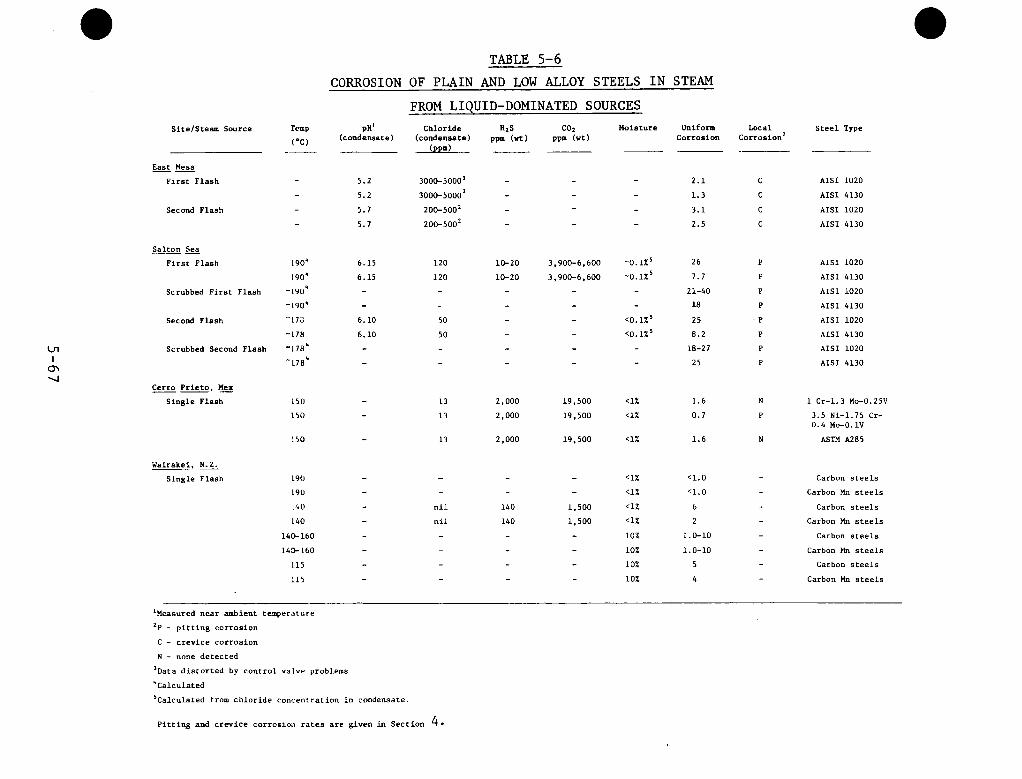
S i t e l s t e a m Source
East Mesa ~- F i r s t F lash
Second Flash
Sa l ton Sea ___- F i r s t Flash
Scrubbed F i r s t Flash
Second Flash
Scrubbed Second Flash
Cerro P r i e t o . M f
S i n g l e F lash --
Wairakei, N&
S i n g l e Flash
Temp
('C) ____
-
190*
-LYok
I90*
- L O O *
-173
-178
-178*
-L78*
150
15il
:so
190
190
140
140
140-160
1 4 3 1 6 0
115
:15
TABLE 5-6 CORROSION OF PLAIN AND LOW ALLOY STEELS IN STEAM
FROM LIQUID-DOMINATED SOURCES PH'
(Condensate)
5.2
5.2
5.1
5.7
6.15
6.15 - -
6.10
6.10 -
Chloride (condensate)
( P P d
3000-5000'
3000-50003
200-5002
200-5002
120
120 - - 50
50 - -
1 3
1 3
13
n i l
n i l -
"2s
Ppm (-1
- -
10-20
10-20
-
2,000
2.000
2.000
140
140
co2 ppm ( v t )
- -
3,900-6,600
3,900-6,600 - - - - - -
19,500
19,500
19,500
- -
1,500
1,500 - - -
Uois ture Uniform Corrosion
-
-
-0.1%' -0.1%'
- <0.1x5
<0.1z5
<1%
<1%
<1%
<1%
<1%
<1%
<I%
10%
10%
10%
10%
2 .1
1.3
3.1
2.5
26
7.7
21-40
18
25 8.2
18-27
25
1.6
0.7
1.6
< l . O
c1.0
6
2 1.0-10
1.0-10
5
4
Local Corrosion2
S t e e l Type
AISI 1020
AISI 4130
AISI 1020
AISI 4130
AISI 1020
AISI 4130
AISI 1020
AISI 4130
A I S I 1020
AISI 4130
AISI 1020
AISI 4130
N 1 Cr-1.3 Mo-O.25V
P 3.5 Ni-1.75 Cr- 0.4 Mo-O.1V
N ASTM A285
Carbon s t e e l s
Carbon Mn s t e e l s
Carbon s t e e l s
Carbon Mn s t e e l s
Carbon s t e e l s
Carbon Mn s t e e l s
Carbon s t e e l s
Carbon Mn s t e e l s
'Measured near ambient temperature
2~ - p i t t i n g cor ros ion
C - c r e v i c e cor ros ion
N - none d e t e c t e d
'Data d i s t o r t e d by c o n t r o l va lve problems
"Calculated
'Calculated from c h l o r i d e concent ra t ion i n condensate.
P i t t i n g and c r e v i c e cor ros ior i r a t e s a r e given in Sec t ion 4 .
it is called fatigue. When the applied stress range is plotted against the logarithm of the number of cycles to failure (S/N plot), the cycle-to-fail curve becomes asymptotic to a limiting value of stress, and below this stress there will be no failure, no matter how long the test. This is the "fatigue limit" (GI-122, WE-317).
When the metal is exposed to a corrosive environment while under cyclic stress, the S/N graph never becomes asymptotic to the zero stress line. The corrosion fatigue 1imit.is the greatest unit stress which may be applied under given conditions of stress, rate of stress application, temperature, and corro- sive environment without causing it to fail in a given number of cycles of stress (WE-317). The values for "corrosion-fatigue limits" are useless, except for comparison within one set of tests, unless the number of cycles and cycle rate are given.
The combined effects of cyclic stress and corrosion are often far more severe than the simple sum of their actions.
5.8.2.1 Low Alloy Steels
Based on tests of two alloys at Cerro Prieto, Mexico, corrosion fatigue of low alloy steels is a significant factor in material selection and design. After 150 days exposure to nonaerated steam, the reduction in fatigue endurance limit (FEL) of 1Cr- 1.3Mo- 0.2 5V [ Rb% 641 was 27.8% while 3.5Ni- 1.7 5Cr -0.4Mo - 0.1V [Rb%68] showed a 38.6% reduction of FEL. These specimens were not under cyclic stress during exposure. Cyclic loading during exposure would have caused greater loss of endurance.
Some of the considerations for low alloy steels in contact with corrosive liquids are discussed below in relation to corrosion fatigue.
5-68
Tests on carbon s teels and low and middle a l l o y s t e e l s i n f r e s h , s a l t and seawater show t h a t endurance l i m i t s i n a moderately co r ros ive medium, ( i . e . s a l t wa te r ) , a r e p r a c t i c a l l y independent of t h e chemical composition of t h e s tee l (ME-A-243).
A series of cor ros ion f a t i g u e tes ts w e r e done i n a s o l u t i o n conta in ing 34,400 ppm C 1 so lu t ion with a d d i t i o n s of C 0 2 , H 2 S and 0 2 .
10 Hz (ME-A-243). Chloride had no s i g n i f i c a n t e f f e c t on t h e f a t i g u e endurance of low a l l o y s teels . In a n e u t r a l , a i r - f r e e (<0.1 ppm 02) s o l u t i o n , t h e f a t i g u e endurance l i m i t (compared t o t h e f a t i g u e endurance l i m i t i n a i r ) increased s l i g h t l y .
A I S 1 1035 specimens were s t r e s s e d l o 7 cyc les a t
Addition of 3000 pprn H2S t o the ch lo r ide s o l u t i o n lowered t h e pH t o 4.5. cracking and hydrogen b l i s t e r i n g occurred. The e f f e c t of H 2 S on harder m a t e r i a l s may be much more severe . These m a t e r i a l s w i l l be cold-worked under c y c l i c s t r e s s and may become suscep- t i b l e t o s u l f i d e stress cracking as w e l l a s cor ros ion f a g i t u e .
The endurance l i m i t decreased 20%, and
- Addition of 700-800 ppm f r e e C 0 2 and 250-300 ppm H C 0 3
t o t h e ch lo r ide s o l u t i o n reduced t h e pH t o 5 . 5 and reduced t h e f a t i g u e endurance l i m i t 41%. Many cracks w e r e observed. A l - though C02 does no t cause stress cor ros ion cracking, i t appea r s t o be an e f f e c t i v e cracking agent when combined with c y c l i c stress.
The combined e f f e c t of C 0 2 and H 2 S i s worse than the sum of t h e i r a c t i o n s . I n a ch lo r ide s o l u t i o n conta in ing 700-800 ppm f r e e C 0 2 and 60-70 ppm H2S, t h e f a t i g u e endurance l i m i t decreased 62%. Both p i t t i n g and su r face cracking w e r e observed.
5-69
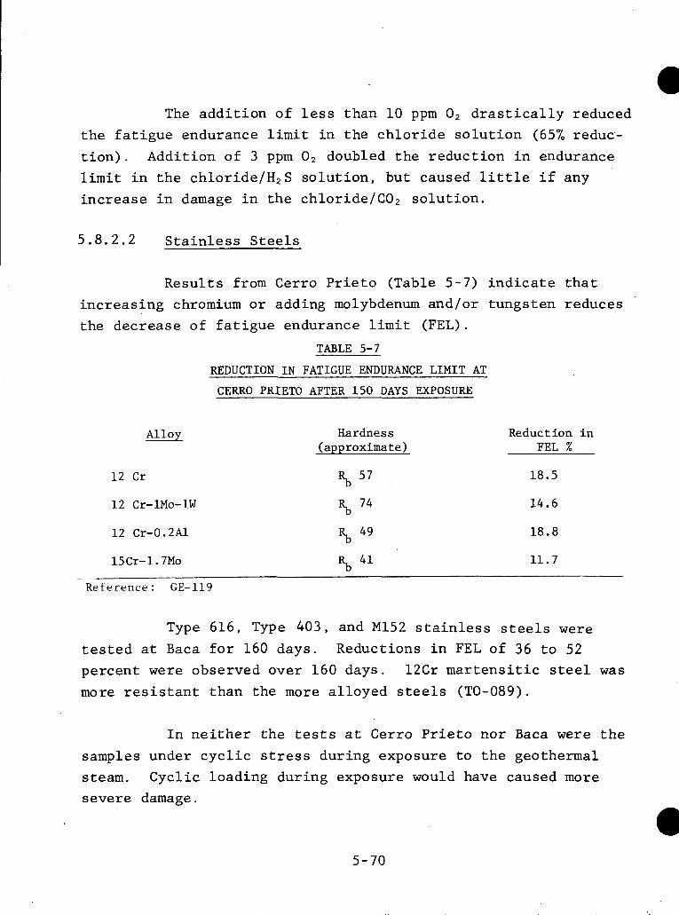
The add i t ion of less than 10 ppm O2 d r a s t i c a l l y reduced t h e f a t i g u e endurance l i m i t i n t he c h l o r i d e s o l u t i o n (65% reduc- t i o n ) . Addition of 3 ppm O 2 doubled t h e reduct ion i n endurance l i m i t i n t h e chloride/H,S s o l u t i o n , but caused l i t t l e i f any increase i n damage i n t h e chloride/C02 so lu t ion .
5 . 8 . 2 . 2 S t a i n l e s s Steels
Resul t s from Cerro P r i e t o (Table 5 -7 ) i n d i c a t e t h a t increas ing chromium o r adding molybdenum and/or tungsten reduces the decrease of f a t i g u e endurance l i m i t (FEL).
TABLE 5-7
REDUCTION I N FATIGUE ENDURANCE LIMIT AT
CERRO PRIETO AFTER 150 DAYS EXPOSURE
Alloy
12 Cr
Hardness (approximate)
Reduction in FEL %
18.5
14.6
18.8
11.7
% 74
% 49
%I 41
12 Cr-1Mo-1W
12 Cr-0.2Al
15Cr-1.7Mo
Reference : GE-119 - ..
Type 616, Type 4 0 3 , and M152 s t a i n l e s s s teels were t e s t e d a t Baca f o r 160 days. Reductions i n FEL of 36 t o 52 percent w e r e observed over 160 days. 1 2 C r m a r t e n s i t i c s teel was more r e s i s t a n t than the more a l loyed s tee ls (TO-089).
I n n e i t h e r t he tes ts a t Cerro P r i e t o nor Baca w e r e t h e samples under c y c l i c s t ress during exposure t o t h e geothermal steam. Cyclic loading during exposure would have caused more severe damage.
5-70
The stainless steels are more resistant to corrosion- fatigue than the low alloy and carbon steels. most effective alloying element in the absence of H 2 S , while nickel is more effective against H2S (WE-317). Best results are obtained with a combination of chromium and nickel ( G I - 1 2 2 ) . Molybdenum is also beneficial (WE-317).
Chromium is the
This problem has been encountered at the Cerro Prieto Measures taken to prevent turbine damage are geothermal plant.
I given in Appendix A . 2 . 4 . 2 . I
5 . 8 . 3 Exf o 1 ia t i on
Exfoliation of iron sulfide scales from steam lines is another potential source of damage to turbines operating directly on flashed steam. carrying steam containing H2S. coatings to crack and flake off. stream of the turbine, the scale particles can be carried to the turbine causing erosion and possibly erosion-corrosion damage.
Iron sulfide coatings form on steel pipes There is a tendency for these
If this occurs in lines up-
A much slower exfoliation of magnetite scales has
In most cases no damage was noted caused serious damage to turbines in high temperature-high pres- sure fossil fuel plants. until the plant was 10-15 years old. the need for close monitoring and frequent inspection of geo- thermal turbines.
This experience accentuates
I

6.0 NONMETALLIC MATERIALS
The search for construction materials in geothermal environments has concentrated primarily on metallic materials, but applications of nonmetallic materials are receiving increas- ing attention. Nonmetallic materials are required in some geo- thermal operations such as elastomers in drilling operations. In other areas, they may be cost-effective replacements for me- tallic materials. Nonmetallic materials have some advantages. They are generally resistant to corrosion at conditions that may adversely affect metals and alloys, and their installation costs may be lower than for metals. However, nonmetallic materials are subject to degradation, and geothermal fluids severely test their durability. Nonmetallics are not useful in heat transfer equipment.
.
The performance of nonmetallic materials in geothermal environments is in the early stages of investigation, and the test results are somewhat limited. Some comparisons and trends may be found by examining the results of nonmetallics in desal- ination fluids and from conventional drilling technologies. Testing of nonmetallics as desalination materials has been con- ducted in flowing sea water up to 250°F (121OC). temperatures are somewhat low f o r some geothermal applications, the data are useful as general guidelines.
Although these
Nonmetallic materials that may find geothermal appli- cations are:
1) concrete polymer composites, 2) cements, 3 ) elastomers, 4 ) fiber reinforced plastic laminates,
6 - 1
5) thermoplastics, 6) fiber reinforced plastic and coated pipe, and 7) paints and coatings.
No systematic attempt has been made to identify processing steps in a geothermal facility where nonmetallics may be used.
6.1 Concrete Polymer Composites
Brookhaven National Laboratory is conducting a program to develop polymer concrete materials for geothermal app'lica- tions. Polymer formulations and polymer concrete composites which can be used as materials of construction for handling geo- thermal brines and steam at temperatures up to 260°C (500'F) are being investigated.
Formulations with the following constituents have pro- duced monomer systems suitable for geothermal conditions.
1) styrene - trimethylolpropane trimethacetylate (TMFTMA)
2) styrene - acrylonitrile - TMPTMA
3 ) Derakane 0- triallyl cyanurate
Acrylamide, methacrylamide, and crosslinking agents are being added to styrene - acrylonitrile formulations to determine the optimum compositions. dependent upon the aggregate composition. polymer concrete materials containing mixtures of silica sand and portland cement have been resistant to geothermal brine and steam. The presence of portland cement in the aggregate greatly
The durability of polymer concrete is Above 218OC, only
6-2
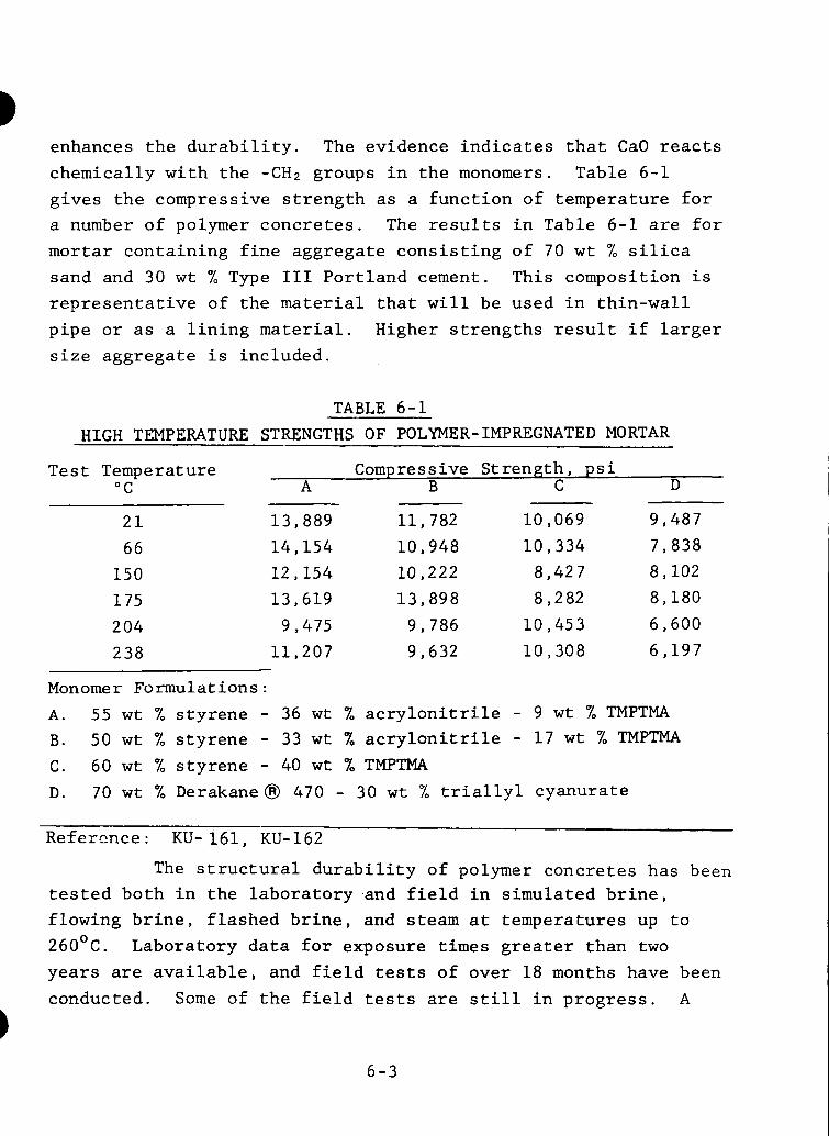
enhances the durability. The evidence indicates that CaO reacts chemically with the -CH2 groups in the monomers. Table 6-1 gives the compressive strength as a function of temperature for a number of polymer concretes. The results in Table 6-1 are for mortar containing fine aggregate consisting of 70 wt % silica sand and 30 wt % Type 111 Portland cement. This composition is representative of the material that will be used in thin-wall pipe or as a lining material. Higher strengths result if larger size aggregate is included.
TABLE 6-1 HIGH TEMPERATURE STRENGTHS OF POLYMER- IMPREGNATED MORTAR
Te s t Temp e r at ure Compressive Strength, psi "C A B C D
21 13,889 11 782 10,069 9 487 66 14 154 10,948 10 334 7,838 150 12,154 10,222 8,427 8,102 175 13 619 13 898 8,282 8,180 204 9,475 9,786 10,453 6 600 238 11,207 9 632 10,308 6,197
Monomer Formulations : A. 55 wt % styrene - 36 wt % acrylonitrile - 9 wt % TMPTMA B. 50 wt % styrene - 33 wt 7, acrylonitrile - 17 wt % TMPTMA C. 60 wt % styrene - 40 wt % TMPTMA D. 70 wt % Derakanea 470 - 30 wt X, triallyl cyanurate
Refermce: KU-161, KU-162
The structural durability of polymer concretes has been tested both in the laboratory and field in simulated brine, flowing brine, flashed brine, and steam at temperatures up to 26OoC. Laboratory data for exposure times greater than two years are available, and field tests of over 18 months have been conducted. Some of the field tests are still in progress. A
6-3
summary of t h e r e s u l t s of labora tory and f i e l d tes ts i s given i n Table 6-2.
6 . 2 Cements
Cements f i n d poss ib l e app l i ca t ions a s cor ros ion resis- t a n t l i n i n g materials and i n w e l l cons t ruc t ion .
Improved cementing ma te r i a l s f o r t h e cons t ruc t ion of geothermal w e l l s are needed t o increase we l l l i f e expectancy. Spec i f i ca t ions f o r w e l l cementing ma te r i a l s a r e l i s t e d below:
1) Compressive s t r e n g t h , >lo00 p s i 2 4 hours a f t e r placement.
2 ) Permeabili ty t o water , <0.1 m i l l i Darcy.
3) Bond s t r e n g t h t o s t e e l cas ing , > l o p s i .
4 ) S t a b i l i t y , no s i g n i f i c a n t reduct ion i n s t r e n g t h o r increase i n permeabi l i ty a f t e r prolonged exposure a t 400°C (%750"F) t o 25% br ine so lu- t i o n s , f l a shed b r i n e , o r dry s t e a m .
5 ) Placement a b i l i t y , capable of 3 t o 4 h r . r e t a r d a t i o n a t expected placement temperatures.
6 ) Compatibil i ty of t h e cement with d r i l l i n g mud.
7) Non-corrosive t o s teel w e l l casing.
Polymer concretes and inorganic cements such as C-S cements and phosphate bonded g l a s s cements a r e being i n v e s t i - gated as p o t e n t i a l cementing materials.
6-4
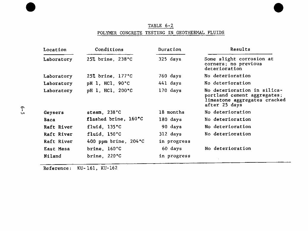
Location
TABLE 6-2 POLYMER CONCRETE TESTING IN GEOTHERMAL FLUIDS
Conditions Duration Results
Laboratory
Laboratory Laboratory Laboratory
Geysers Baca Raft River Raft River Raft River East Mesa Niland
25% brine, 238°C ~
325 days
25% brine, 177°C pH 1, HC1, 90°C pH 1, HC1, 200°C
steam, 238°C flashed brine, 160'C fluid, 135°C fluid, 150°C 400 ppm brine, 204°C brine, 160°C brine, 220°C
760 days 441 days 170 days
18 months 180 days 90 days 312 days in progress 60 days in progress
Some slight corrosion at corners; no previous deterioration No deterioration No deterioration No deterioration in silica- portland cement aggregates; limestone aggregates cracked after 25 days No deterioration No deterioration No deterioration No deterioration
No deterioration
Reference : KU- 161, KU-162
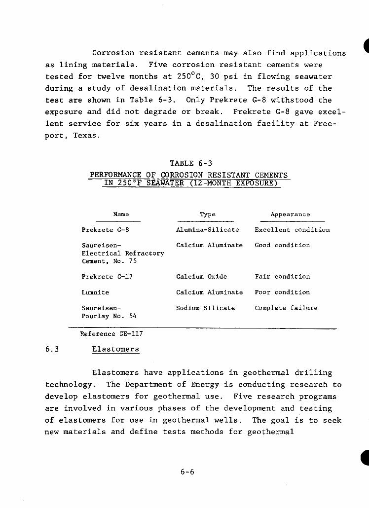
Corrosion resistant cements may also find applications as lining materials. tested for twelve months at 25OoC, 30 psi in flowing seawater during a study of desalination materials. The results of the test are shown in Table 6-3. Only Prekrete G-8 withstood the exposure and did not degrade or break. lent service for six years in a desalination facility at Free- port, Texas.
Five corrosion resistant cements were
Prekrete G-8 gave excel-
TABLE 6-3 PERFORMANCE OF CORROSION RESISTANT CEMENTS
IN 250°F S a m T E R (12-MONTH E X P O S U T
Name Type Appearance
Prekrete G-8 Alumina-Silicate Excellent condition
Saureisen- Calcium Aluminate Good condition Electrical Refractory Cement, No. 75
Calcium Oxide Fair condition Prekrete C-17
Lumnite Calcium Aluminate Poor condition
Saureisen- Sodium Silicate Complete failure Pourlay No. 54
2eference GE-117
6.3 Elastomers
Elastomers have applications in geothermal drilling technology. develop elastomers for geothermal use. are involved in various phases of the development and testing of elastomers for use in geothermal wells. The goal is to seek new materials and define tests methods for geothermal
The Department of Energy is conducting research to Five research programs
6-6
applications. bit cutter cone seals. to applied development and include synthesis of new polymers, investigation of new but available (at high cost) elastomers, modification of commonly known materials and development and evaluation of test methods.
Of particular interest are packer seals and drill The approaches range from basic research
The goals of the five research programs are described below.
1.) Test seals produced from new materials. A spe- cial device which simulates the environment of the cutter cone has been developed.
2 . ) Develop packer seals and a simulated test device for down-hole condition duplication. packer seals are common hydrocarbon elastomers.
The materials used for
3 . ) Synthesize new quinoxaline and styrene type elas-
Tensile properties, thermal stabil- tomers and investigate the modification of existing commercial materials for packer seals. ity and stress relaxation tests are being conducted.
4 . ) Synthesize new fluorinated elastomer sys’tems and look at carboranesiloxane (Ucarsil) systems. These materials are being tested for thermal and hydrolytic stability, compres- sion set, hardness and tensile properties.
5 . ) Study the feasibility and value of coating O-ring seals in an RF glow discharge apparatus.
The results of these ongoing studies are described in Appendix D.
6 - 7
These programs have revealed that conditions are so
severe and different from those in other applications of elas- tomers that nearly all previous test data are of very little value. Thermal stability is usually measured in an oxidative atmosphere. The results of thermal stability tests give little indication of polymer performance under typical geothermal stresses such as reducing atmospheres and hydrolysis. Further- more, some unpredicted reactions can take place at the extreme pressures of the well. Elastomers for geothermal uses must be investigated under appropriate test conditions.
6 . 4 Fiber Reinforced Laminates
Fiber reinforced plastic (FRP) laminates may be useful because of their high corrosion resistance and reasonable cost. FRP materials have not been adequately tested in geothermal systems, but an indication of their potential can be obtained from the results of testing in desalination environments (GE- 117). Table 6-9 summarizes the results of exposing FRP lami- nates to flowing seawater at 250'F for 15 months. peratures, only Bis-A epoxy systems and halogenated vinylester Derkane @ systems gave acceptable results. Testing of FRP ma- terials in geothermal environments is required.
At high tem-
6.5 FRP and Coated Pipe
Nonmetallic piping materials have been tested in de- salination facilities (GE-117). Glass reinforced epoxy piping systems were found to be acceptable for handling brines in the 210'F to 250'F range. Additional testing of nonmetallic pipes should be conducted for geothermal applications.
6 - 8
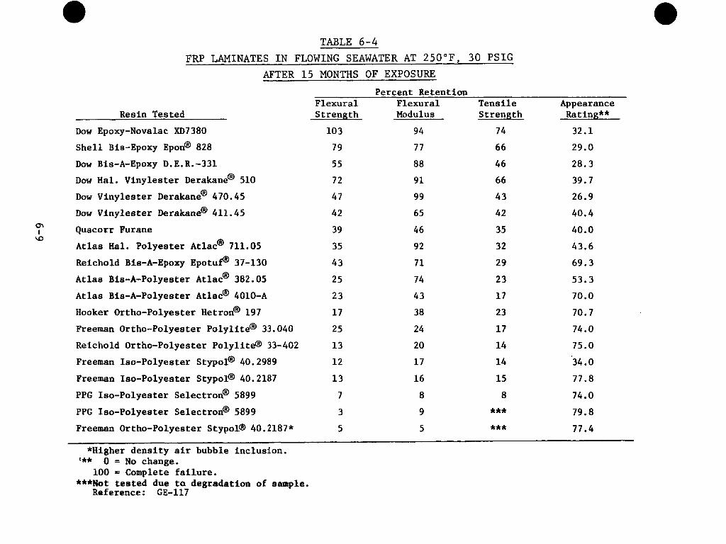
TABLE 6-4
FRP LAMINATES I N FLOWING SEAWATER AT 2 5 0 " F , 30 PSIG AFTER 15 MONTHS OF EXPOSURE
Resin Tested
Dow Epoxy-Novalac XD7380
Shell Bis-Epoxy Epon@ 828
DOW Bis-A-EpOXy D. E. R. -331 Dow Hal. Vinylester Derakane@ 510
Dow Vinylester Derakane@ 470.45
Dow Vinylester Derakane@ 411.45
Quacorr Furane
Atlas Hal. Polyester Atlac@ 711.05
Reichold Bis-A-Epoxy Epotuf@ 37-130
Atlas Bis-A-Polyester Atlac@ 382.05
Atlas Bis-A-Polyester Atlac@ 4010-A
Hooker Ortho-Polyester Hetron@ 197
Freeman Ortho-Polyester Polylite@ 33.040
Reichold Ortho-Polyester Polylite@ 33-402
Freeman Iso-Polyester Stypol@ 40.2989
Freeman Iso-Polyester Stypol@ 40.2187
PPG Iso-Polyester Selectron@ 5899
PPG Iso-Polyester Selectron@ 5899
Freeman Ortho-Polyester Stypol@ 40.2187*
m I a
Percent Retention F1 exural Flexural Tensile Appearance S t reng th Modulus Strength Rating**
10 3 94 74 32.1
79 77 66 29.0
55 88 46 28.3
72 91 66 39.7
47 99 43 26.9
42 65 42 40.4 39 46 35 40.0
35 92 32 43.6
43 71 29 69.3
25 74 23 53.3
23 43 17 70.0
17 38 23 70.7
25 24 17 74.0
13 20 14 75.0
12 17 14 34.0
13 16 15 77.8
7
3
8 8 74.0
9 *** 79.8
5 5 *** 77.4
*Higher density air bubble inclusion. *** 0 = No change.
***Not tested due ta degradation of sample. 100 = Complete failure.
Reference : GE-117
6.6 Thermoplastics
Polysulfone has shown no sign of thermal distortion or change in physical properties in seawater tests at 250'F. The durability of thermoplastics in geothermal environments is unproven.
6-10
7.0 REFERENCES
AU-064
BA-539
BA-550
BA-557
BA-563
BA-566
BE-A-5 0 1
Austin, Arthur L . , e t a l . , comps. and e d . , The LLL Geothermal Energy Program, S ta tus Report , January 1976 - January 1 9 7 7 , UCRL-50046-76, Livermore, CA, Lawrence Livermore Labs. , A p r i l 1 9 7 7 .
Banning, Lloyd H. and Laurance L. Oden, Corrosion Resistance of Metals i n Hot Brines: A L i t e r a t u r e Review, I C 8601, Albany, OR, Albany Metallurgy Center, 1973.
Bates, J . F . , "Sulfide Cracking of High Yield Strength S t e e l s i n Sour Crude Oils", Mater. Pro t . - 8(1), 33-40 (1969).
Baker, H. R . , e t a l . , " F i l m and pH Ef fec t s i n t h e Stress Corrosion Cracking of Type 304 S t a i n l e s s Steel", Corrosion 26(1) , 420 (1970).
Baldy, M. F . , "Sulf ide S t r e s s Cracking of Steels f o r A P I Grade N-80 Tubular Products", Corrosion 1 7 ,
509t (1961).
B a t t l e , Jack L . , T . V. M i l l e r , and Martin E . True, "Resistance of Commercially Avai lable High Strength Tubular Goods t o Su l f ide Stress Cracking", Mater. Perform. 1975 (June) , 11.
Beck, T . R . , "Electrochemical Aspects of Titanium Stress Corrosion Cracking", i n Fundamental Aspects of S t r e s s Corrosion Cracking, Ohio S t a t e Univer- s i t y , Sept . 1967 , Conference Proceedings, pp . 605ff .
7 - 1
BO-270 Bohlmann, E . G . and F. A. Posey, "Aluminum and Titanium Corrosion i n Sa l ine Waters a t Elevated Temperatures", i n Proc. F i r s t I n t ' l . Symp. Water Desa l ina t ions , Washington, D. C . O c t . 1965, vo l . 1, Washington, D.C., GPO, 1967, pp. 306-25.
BO-A-313
BO -A- 31 4
BO -A- 32 3
Booker, C . J . L . , "Some Electrochemical Factors i n t h e Stress Corrosion of a-brass" , i n Fundamen- t a l Aspects of Stress Corrosion Cracking, Ohio S t a t e Univers i ty , Sept. 1 9 6 7 , Conference Proceed- ings , pp. 178ff .
Boyd, W. K . , "Stress Corrosion Cracking of Titanium and i t s A l l o y s " , F u n d a m e n t a l A s p e c t s o f Stress
Corrosion Cracking, Ohio S t a t e Univers i ty , Sept . 1967, Conference Proceedings, pp . 593ff .
Bond, A. P. and E. A. L i z lovs , " In te rgranular Corrosion of F e r r i t i c S t a i n l e s s S tee l s " , J . Elec- trochem. SOC. 116 ( 9 ) , 1305 (1969).
BU-A-307 Bu t l e r , G . and H. C . K. I son , "Model Boi le r Tes ts on t h e Inf luence of t he Copper Content of t h e Steel on t h e Corrosion of Tubes i n A r t i f i c i a l Sea Water", I n s t . Marine Engrs. 6 9 , 212 (1957).
CA-430 Car t e r , J . P. and Stephen D . Cramer, "Corrosion Resistance of Some Commercially Available Metals and Alloys t o Geothermal Brines", i n Corrosion Problems i n Enerzy Conservation and Generation, New York, O c t . 1974, Symposium Proceedings. Pr inceton, N J , Electrochemical Society, Corrosion Divis ion, 1974, pp. 240-50.
7-2
Environments", College P a r k , M D , Bureau o r iviines, College Park Metallurgy Research Center, undated.
CH-A-453 Chin, Robert J . and Ken Nobe, "Elec t rodisso lu t ion Kine t ics of I ron i n Chloride Solut ions 111. Acidic Solut ions" , J . Electrochem. SOC. 119(11), 1457 (1972).
Ciha l , Vladimir, "Meta l lurg ica l Aspects of Knife- Line Attack on S t a b i l i z e d S t a i n l e s s Steels", i n Localized Corrosion, Williamsburg, VA, Dec. 1 9 7 1 , Conference Proceedings, R. W. S t aeh le , e t a l . , e d . , Houston, NACE, 1974, pp. 520ff .
C I -A- 02 7
CO-598 Covington, Loren C. , "Titanium Solves Corrosion Problems i n Petroleum Processing", Met. Prog. 1 9 7 7 (Feb . ) , 38-45.
CO-602 Covington, L . C . , " P i t t i n g Corrosion of Titanium Tubes i n Hot Concentrated Brine Solut ions" , i n Galvanic and P i t t i n g Corrosion-Field and Laboratory S t u d i e s . ASTM STP 576 , Robert Baboian, e t a l . , eds . ~~
Phi l ade lph ia , ASTM, 1976, pp . 147f f .
CR- 162 Cramer, Stephen D . , "The S o l u b i l i t y of Oxygen i n
Geothermal Brines", i n Corrosion Problems i n Energy Conversion and Generation, New York, O c t . 1974, Symposium Proceedings, pp. 251-621
DA-268 Dana, A. W. and W. B. Delong, "Stress-Corrosion I - Cracking Test" , COrrOSiOn 1 2 ( y -
DE-A-315
DU-153
FO-118
FO-119
FO-120
FO-123
FR-233
FR- S-2 6 7
DeWaard, C. and D. E. Mill iams, "Carbonic Acid Corrosion of Steel", Corrosion 31)5) , 177(1975).
Dundas, H. J . , Ef fec t of Molybdenum on Stress Cor- rosion Cracking of Aus ten i t i c S t a i n l e s s S t e e l , Ann Arbor, M I , Climax Molybdenum Co., S e p t . 1975.
Fontana, Mars G . and Norbert D . Greene, Corrosion Engineering, N Y , McGraw-Hill, 1967 .
Fooks, A . C . L . , "The Development of Casings f o r Geothermal Boreholes a t Wairakei , New Zealand", paper G / 1 6 , i n United Nations Conference on New Sources of Energy, Rome, August 1961, vo l . 3 , NY, United Nations, 1964, pp. 170ff .
Fos t e r , P. K . , T . Marshall , and A. Tombs, ''Corro- s ion Inves t iga t ions i n Hydrothermal Media a t Wairakei, New Zealand", paper G / 4 7 , i n United Nations Conference on New Sources of Energy, Rome, August 1 9 6 1 , vo l . 3 , NY, United Nat ions, 1964, pp . 186ff .
Fos t e r , P . K. , "Thermodynamic S t a b i l i t y of I ron and i t s Compounds i n Hydrothermal Media", N . Z . J . Sc i . 2 ( 3 ) , 422-30 (1959).
F rase r , J . P. and R. S. Treseder , "Cracking of High Strength Steels i n Hydrogen Sul f ide Solutions", Corrosion 8(10), 342 (1952).
Franson, E. A . , "What's New with Titanium i n t h e S a l t Related Indus t r i e s " , presented a t t h e S a l t I n s t i t u t e Corrosion Seminar, Chicago, June 1 9 7 7 .
7-4
G E - 1 1 7
GE-119
G I - 122
GO-233
GR-233
GR-A- 330
HA-628
HI-191
George, P . F . , J . A. Manning, J r . , and C . F. Schr ieber , Desa l ina t ion Materials Manual , Dow Chemical Co., May 1975.
Geothermal Resources Council , Second Workshop on Mate r i a l s Problems Associated wi th t h e Develop- ment of Geothermal Energy Systems, E l Centro, CA, May 1975, proceedings, BuMines OFR 128-76, PB 2 6 1 349, Davis, CA, 1976.
G i l b e r t , P . T . , l lCorrosion-Fatigue", Metal l . R e v . - 1, 379-417 (1956).
Goldberg, A l f r ed , Comments on t h e Use of 316L S t a i n l e s s S t e e l Cladding a t t h e Geothermal Niland T e s t F a c i l i t y , UCID-17113, AEC Contract N o . W-7405-Eng-48, Livermore , CA, Univ. o f C a l i f o r n i a , Lawrence Livermore Lab . , Apr i l 1 9 7 6 .
Grudger, L. , "Future Trends i n U t i l i z a t i o n of Coal Energy Conversion", Energy Dig. 3 ( 1 ) , 2-6 (1974).
Greco, Edward C. and W i l l i a m B. Wright, "Corrosion of I ron i n an H2S-CO2-HzO System", Corrosion 18 , 119t-24t (1962).
H a l l , Beverly A . , "Materials Problems Associated w i t h t h e Development of Geothermal Energy Resources," Davis, CA, Geothermal Resources Council , May 1975.
Hines, J . G . and T . P. Hoar, "The Stress-Corrosion Cracking of Austenitic S t a i n l e s s S t e e l s , P a r t 2 , F u l l y Softened, Strain-Hardened, and Ref r ige ra t ed Mater ia l" , J . I ron S t e e l I n s t . 1 9 5 6 ( 0 c t . ) , 1966.
7-5
HO-348 Hoar, T. P , and J . G. Hines, "The Stress-Corrosion Cracking of Aus ten i t i c S t a i n l e s s S t e e l s , Par t 1, Mechanism of t h e Process i n Hot Magnesium-Chloride Solut ions" , J . I ron S t e e l I n s t . 1 8 2 ( 2 ) , 124-43 (1956) .
HU-199 Hudgins, Charles M . , J r . , "Review of Sul f ide Corrosion Problems i n t h e Petroleum Industry", Mater. P ro t . 8 ( 1 ) , 41-47 (1969) .
Hu-200 Hudgins, C . M . , e t a l . , "Hydrogen Sul f ide Cracking of Carbon and Alloy S tee l s " , Corrosion 2 2 ( 8 ) , - 238- 51 (1966) .
HU-A-2 3 3 Hudson, P. E . , e t a l , "Absorption of Hydrogen by Cathodically Pro tec ted S tee l" , Corrosion 2 4 ( 7 ) , 1 8 9 (1968) .
I O - A - 2 1 I o f a , Z . A . , V. V . Batrakov and Cho-Ngok-Ba, "Influence of Anion Adsorption on the Action of I n h i b i t o r s on t h e Acid Corrosion of I ron and Cobalt", Electrochim. Acta 9 , 1645-53 (1964) .
I J - A - 0 0 3 Ijzermans, A. B. and Van Der Krogt, " P i t t i n g Corrosion of an Aus ten i t i c C r - N i S t a i n l e s s S t e e l i n H 2 S 0 4 containing HPS", Corros. Sc i . 8 , '679-87 (1968) -
50-262 Johnson, M. J . , "Relative C r i t i c a l P o t e n t i a l s f o r P i t t i n g Corrosion of Some S t a i n l e s s ,S tee ls" , i n Localized Corrosion Cause of Metal F a i l u r e , ASTM STP 5 1 6 , Phi lade lphia , ASTM, 1 9 7 2 , pp. 262-72.
7-6
L d
I
w
KA-280
KA-A-301
KA-A-302
KU-161
KU-162
LA-312
1
Kane, Russell D. and J. Brison Greer, "Sulfide Stress Cracking of High-Strength Steels in Laboratory and Oilfield Environments", Paper No. SPE 6144, NY, AIME, 1976.
Kane, R. D., et al., "Factors Influencing the Embrittlement of Cold Worked High Alloy Materials in H2S Environments", Corrosion 33(9), 309 (1977).
Kawashima, A., A. K. Agrawal, and R. W. Staehle, "Stress Corrosion Cracking of Admiralty Brass in Nonamxnoniacal Sulfate Solutions", J. Electro- chem. SOC. 124(11), 1822 (1977).
Kukacka, L. E., et al., Alternate Materials of Construction for Goethermal Applications, Progress Report No. 13 April - June 1977, ERDA Contract No. EY-76-C-02-0016, BNL 50699, Upton, NY, Brookhaven National Laboratory, Dept. of Applied Science, Process Technology Div., undated.
Kukacka, L. E., et al., Alternate Materials of Construction for Geothermal Applications, Progress Report No. 14 July - September 1977, ERDA Contract No. EY-76-C-02-0016, BNL 50751, Upton, NY, Brook- haven National Laboratory, Dept. of Applied Science, Process Technology Division, undated.
Lawrence Berkeley Laboratory, Geothermal Water Data File, updated periodically, Berkeley, CA, various dates.
r
7-7
LA-A-338
LE-A-338
LI-A-230
LO-208
LO-A- 240
MA-668
MA-672
Latanision, R. M. and R. W. S taehle , "Stress Corrosion Cracking of Iron-Nickel-Chromium Alloys", i n Fundamental Aspects of Stress Corrosion Crack- ing, Ohio State University, Sept. 1967, Conference Proceedings, pp. 2 14f f .
Leckie, H. P . , "A Contribution t o the Applicabi l i ty of C r i t i c a l P i t t i n g Potent ia ls" , J . Electrochem. SOC. 117(3), 1152 (1970).
Lizlovs, E. A . , "Corrosion Resistance of Types 316 and 317 Stainless Steels i n Simulated SO2 Scrubber Environment", J. Electrochem. Soc. 124(12), 1887 (1977).
Lombard, G. L. , Test and Evaluation of a Geothermal Heat Exchanger, f i n a l repor t , PB 247 218, EPRI 376, RP 376, San Diego, CA, San Diego Gas & Electric Co., Sept. 1976.
Loginow, A.W., J . F. Bates, and W. L. Mat.hay, "New Alloy Resists Chloride Stress Corrosion Cracking," Mater. Perform. 11(5) , 35 (1972).
Marshall, T. and W. R. Braithwaite, "Corrosion Control i n Geothermal Systems," i n Geothermal Energy, R e v i e w of Research and Development, Earth Science Series No. 1 2 , P a r i s , UNESCO, 1973, pp. 151-60.
Marshall, T. and A. J. Hugil l , "Corrosion by Low-pressure Geothermal Steam," Corrosion 13, 329t (1957).
7-8
MA-682
MA-705
MA-A-770
ME-A-243
ME-S-250
MI-305
NA-383
Marshall T. and A. Tombs, "Delayed Fracture of Geothermal Bore Casing Steels," Aust. Corros. Enp;. 13(9), 7 (1969).
Mauney, D. A., E. A. Starke, Jr., and R. F. Hochman, "Hydrogen Embrittlement and Stress Corrosion Cracking in Ti-A1 Binary Alloys," Corrosion 29(6), 241 (1973).
Makrides, A.C. and Norman Hackerman, "Effect of Thiourea Compounds on Dissolution Rate of Iron and Mild Steel," I&EC 47(9), 1773 (1955).
Mehdizadeh, Parvis, R. L. McGlasson, and J. E. Landers, "Corrosion Fatigue Performance of a Carbon Steel in Brine Containing Air, H2S and Con, ' I Corrosion 22 (12) , 325 (1966) .
Mercado, Sergio, "Corrosion by Geothermal Fluids in Cerro Prieto, B.C.N. Mexico," Paper No. 60, Presented at the NACE National Conference, Corro- sion/78, Houston, Texas, March 1978.
Miller, R. L., Results of Short-term Corrosion Evaluation sts at Raft River, TREE-1176, DOE Contract EY-76-C-07-1570, EG&G Idaho, Inc., Oct. 1977.
National Association of Corrosion Engineers, Technical 'Practices Committee, Materials for Valves for Resistance to Sulfide Stress Crack- ing in Production and Pipeline Service, Ma- terial Requirements, NACE Standard MR-01-75, (Replaces NACE Publication 1F166), Houston, Texas, March 1975.
7-9
NA-423 National Association of Corrosion Engineers, Technical Practices Committee, Testing of Metals for Resistance to Sulfide Stress Crack- ing at Ambient Temperature Test Method, NACE Standard TM-01-77, Houston, Texas, July 1977.
NE-207 Neumann, P.D. and J.C. Griess, "Stress-Corrosion Cracking of Type 347 Stainless Steel and Other Alloys in High Temperature Water," Corrosion 19, 345t-53t (1964).
NE-302 Needham, P. B., Jr., et al., Materials for the Construction of Geothermal Resource Recovery Plants, draft report, College Park, MD, College Park Metallurgy Research Centr., 1977.
OH- S - 03 9 Ohki, Teruhisa, et al., "Effect of Inclusions on Sulfide Stress Cracking," Presented at the Symposium on Line Pipe and Tubular Goods, Holly- wood, FL, June 1977.
PE-268 Pessall, N. and J. I. Nurminen, "Development of Ferritic Stainless Steels for Use in Desali- nation Plants , ' I Corrosion 30, 381 (1974).
PO-230 Posey, F. A., A. A. Palko, and A. L. Bacarella, Corrosivity of Geothermal Brines Progress Re- port for Period Ending June 1977, DOE Contract No. W-7405-eng-26, ORNL/TM-6159, Oak Ridge, TN, Oak Ridge National Laboratory, Nov. 1977.
7-10
PU-A-068 Pugh, E. N., J. Y. Craig, and A. J. Sedriks, "The Stress-Corrosion Cracking of Copper, Silver, and Gold Alloys," in Fundamental Aspects
!
,
SC-448
SH-333
of Stress Corrosion Cracking, Ohio State Univer- sity, Sept. 1967, Conference Proceedings, pp. 118ff.
Scale Management in Geothermal Energy Develop- ment, San Diego, CA, Aug. 1976, Conference Proceedings, ERDA Contract No. E(11-1)-2607, Newton, MA, EIC Corp., 1976.
Sheppard, R. S., et al., "Performance of Titanium vs. Other Materials in Chemical Plant Exposures , ' I Corrosion 18, 211t-18t (1962).
SH-S-37 9 Shannon, Donald W., "The Role of Chemical Com- ponents in Geothermal Brines on Corrosion", paper no. 57, presented at the NACE National Conference, Corrosion/78, Houston, TX, March 1978.
SH-381 Shannon, Donald W., Corrosion of Iron-Base Alloys Versus Alternate Materials in Geothermal Brines, interim report, ERDA Contract No. #Y-76-C-06-1830, PLN-2456, Richland, WA, Battelle Pacific Northwest Laboratories, Nov. 1977.
Smith, John H., "Casing Failures in Geothermal Bores at Wairakei," paper G/44, in United Nations Conference on New Sources of Energy, Rome, August - 1961, vol. 3, NY, United Nations, 1964, pp. 254 ff.
,
SM-160
7-11
SM-A-184
SM-A-191
SN-060
SN- 06 1
SP-104
ST-A-563
ST-566
ST-A-570
Smialowski, Michael, Hydrogen in Steel, New York, Pergamon, 1962.
Smith, Carroll A., and Kenneth G. Compton, "Potentials of Selected Metal Alloys in Seawater at Elevated Temperatures," Corrosion 31(a), 320 (1975).
Snape, E., "Roles of Composition and Microstruc- ture in Sulfide Cracking of Steel," Corrosion 23, 154 (1967).
Snape, E. "Roles of Composition and Microstruc- ture in Sulfide Stress Cracking of Steel," Corro- sion 24, 261 (1968).
Spaepen, G. J. and M. J. Fevery-DeMeyer, Electrochemical Corrosion Experiments at Temperatures Above 100°C," Corros. Sci. 7, 405-13 (1967).
Streicher, Michael A . , "Effect of Composition and Structure on Crevice, Intergranular, and Stress Corrosion of Some Wrought Ni-Cr-Mo Alloys ,It Corrosion 32, 79 (1976).
Staehle, R. W., et al., ed., Localized Corro- sion, Williamsburp;, VA, Dec. 1971, Conference Proceedings, International Corrosion Conference Series NACE-3, Houston, TX, NACE, 1974.
Steigerwald, R. F., et al., "The New Fe-Cr-Mo Ferritic Stainless Steels," Corrosion 33(8 ) ,
id 279 (1977).
7-12
I 0
k k
I a
al o
u 5
f k cd al
w 0
k u d
a
a
k 3 u
a
n
0
d
v
I -4
k
u
- - 0 u
w 0
m
2 a al
N
*rl 4
(d
a k 0
w u
v)
s a
ra 0
*rl u
0
m
Ei *rl m 0
k k 0
u
a
n
d
u-
a
k 0
w
co N
0
al a
*VI k 0
3
0
al n
0
c aJ c
o 0 GI
rl
cn c 0 4
m 0
k k 0
U
8 rl m 0
k
k 0
u
rl M
a
p1 u 3
u
*rl u
me
a
lo
a al s m
or(
d
P
3
pc
d
1 U w
0
5 8 3
0
a c cd
s n
d
b
QI d
W
al 0
*I4 3
al k
u
cd c
8 cd pc
0
d
$ c a
u k 0
k
rl
e
n
N h
m
rl
d
v a
n
00 cv e 8 4 m
0
k k 0
U
: H
.VI c
al k 3
u cd a
i3 w 0 u 0
al w
w
w
!il 5 -
m 0
9
m 0
9
L
rl
cd u al a
u
F9
U
U
al k
h
cn L
m
d
I h
k 0
W
cn m
m
al l4
w 0
a s
a s
m
al c rl k
F9
d
cd rl
U
u 0
pc
$
cl
0
3
m
I3 i!l k 0
u
0
3
23 G *rl cd u
u cd
m
sa
l d
cd 3
w .h
k 0
U
al a
*rl k 0
2
a
ad
24 3 N
5
'td 0 *rl
cd c *d
w
c 0
ch u
c43 N
0
4
m
d
3 I
E N
V
I
N
m
m
m
d
rl
co N
0
I
z 0
m
N 0
I
z 4 I
cn 3
N 0
I N
cn
3
TA-136
TO-085
TO-089
TR-054
TR-090
TR- S- 11 9
Tardiff, George E., "Using Salton Sea Geothermal Brines for Electrical Power: A Review of Pro- gress in Chemistry and Materials Technology-1976 Status," preprint, Presented at the 12th Inter- society Energy Conversion Engineering Conference, Washington, DC, Aug. 28-Sept. 2, 1977.
Tolivia, E., "Corrosion Measurements in a Geo- thermal Environment , I ' U.N . Symp. on the De- velopment and Utilization of Geothermal Re- sources, Pisa 1970, Vol. 2 (part 2), pp. 1596- 1601.
Toney, S. M. Cohen, and C. J. Cron, "Metallur- gical Evaluation of Materials for Geothermal Power Plant Applications ," Geotherm. Energy Mag. 5(9), 9 (1977).
Truesdell, Alfred H. and Wendy Singers, "The Calculation of Aquifer Chemistry in Hot-Water Geothermal Systems, USGS J. Research 2 (3), 271-78 (1974).
Troiano, A . R. and R. F. Hehemann, Materials Research and Evaluation for Geothermal Corro- sion Environments, Progress Report for Period December 15, 1975-December 15, 1976, ERDA Contract No. EY-76-5-02-2602, Cleveland, OH, Case Western Reserve University, Dec. 1976.
Troiano, A. R. and R. F. Hehemann, "Hydrogen Sulfide Stress Corrosion Cracking in Materials for Geothermal Power," Paper No. 59, Presented at the NACE National Conference, Corrosion/78, Houston, Texas, March 1978.
7-14
u VO-067 Vollmer, L. W., "The Behavior of Steels in
Hydrogen Sulfide Environments ,'I Corrosioh 14, 324t-28t (1958).
I
I WA-347 Watkins, M. and J. B. Green, "Corrosion Testing of Highly Alloyed Materials for Deep, Sour Gas Well Environments," J. Pet. Tech. 1976 (June), 698-704.
WE-317 Wescott, Blaine B., "Fatigue and Corrosion Fatigue of Steels," Mech. Eng. 60, 813 (1938).
WI-A-317 Wilde, B. E., "The Role of Passivity in the Mechanism of Stress-Corrosion Cracking and Metal Dissolution of 18Cr-8Ni Stainless Steels in Boiling Magnesium and Lithium Chlorides," J. Electrochem. SOC. 118(11), 1717 (1971).
7-15
APPENDIX A
CORROSION EXPERIENCE AT OPERATING UNITED STATES AND FOREIGN GEOTHERMAL POWER PLANTS
A-1
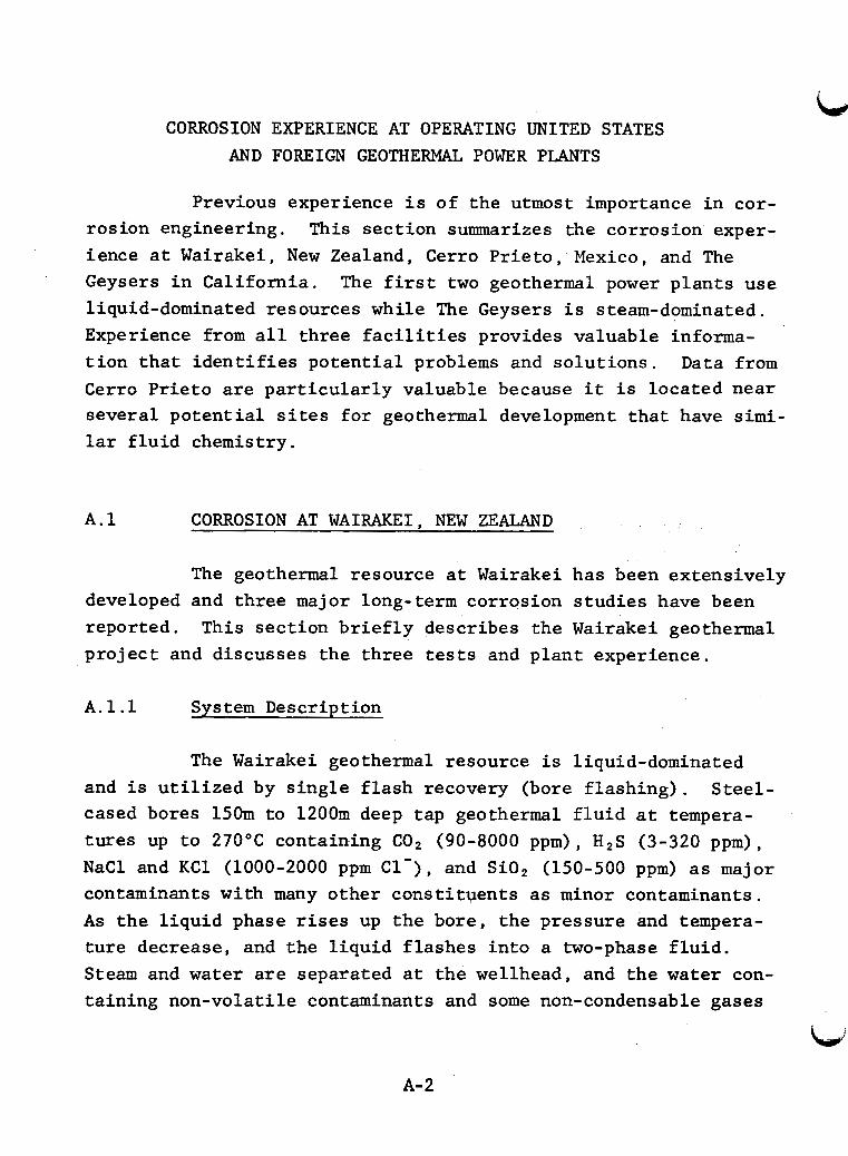
CORROSION EXPERIENCE AT OPERATING UNITED STATES AND FOREIGN GEOWERMAL POWER PLANTS
Previous experience i s of the utmost importance i n cor- rosion engineering. This sect ion summarizes the corrosion exper- ience a t Wairakei, New Zealand, Cerro P r i e to , Plexico, and The Geysers i n Cal i fornia . The f i r s t two geothermal power p lan ts use liquid-dominated resources while The Geysers i s steam-dominated. Experience from a l l three f a c i l i t i e s provides valuable informa- t i o n t h a t i d e n t i f i e s po ten t ia l problems and so lu t ions . Data from Cerro Pr ie to are pa r t i cu la r ly valuable because i t i s located near several poten t ia l s i t e s fo r geothermal development tha t have s i m i - l a r f l u i d chemistry.
A . l CORROSION AT WAIRAKEI, NEW ZEALAND
The geothermal resource a t Wairakei has been extensively developed and three major long-term corrosion s tudies have been reported. p ro jec t and discusses the three tests and p lan t experience.
This sect ion b r i e f l y describes the Wairakei geothermal
A.l.l Sys t e m Description
The Wairakei geothermal resource i s liquid-dominated and i s u t i l i z e d by s ingle f l a sh recovery (bore f lash ing) . Steel- cased bores 150m t o 1200m deep tap geothermal f l u i d a t tempera- tures up t o 270°C containing COP (90-8000 ppm), H2S (3-320 ppm), N a C l and K C 1 (1000-2000 ppm Cl'), and Si02 (150-500 ppm) as major contaminants with many other const i tuents as minor contaminants. As t he l i qu id phase rises up the bore, the pressure and tempera- t u re decrease, and the l iqu id f lashes i n t o a two-phase f l u i d . Steam and water are separated a t the wellhead, and the w a t e r con- ta ining non-volat i le contaminants and some non-condensable gases
A-2
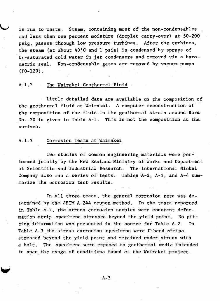
is run t o waste. Steam, containing most of the non-condensables and less than one percent moisture (droplet carry-over) a t 50-200 ps ig , passes through low pressure turbines . After the turbines , the steam ( a t about 40°C and 1 psia) i s condensed by sprays of 02-saturated cold w a t e r i n j e t condensers and removed v i a a baro- metric seal .
r
Non-condensable gases are removed by vacuum pumps (FO-120).
A . 1 . 2 The Wairakei Geothermal Fluid
L i t t l e de ta i led data are avai lable on the composition of the geothermal f l u i d a t Wairakei. the composition of the f l u i d i n the geothermal s'trata around Bore No. 20 i s given i n Table A-1 . This i s not the composition a t the surface.
A computer reconstruct ion of
A.1.3 Corrosion Tests a t Wairakei
Two s tudies of comon engineering materials w e r e per- formed j o i n t l y by the New Zealand Ministry of Works and Department of S c i e n t i f i c and Indus t r i a l Research. The Internat ional Nickel Company a l s o ran a series of t e s t s . Tables A-2 , A-3, and A-4 sum- marize the corrosion test r e s u l t s .
In a l l th ree tes ts , t he general corrosion rate w a s de- termined by the ASTM A 244 coupon method. In the tests reported i n Table A-2, the stress corrosion samples were constant defor- mation s t r i p specimens s t ressed beyond t h e . y i e l d point . No p i t - t i n g information w a s presented i n the source f o r Table A-2. I n Table A-3 the stress corrosion specimens were U-bend strips, s t ressed beyond the y ie ld point and retained under stress with a b o l t . The specimens w e r e exposed t o geothermal media intended to span the range of conditions found a t the Wairakei p ro jec t .
A-3
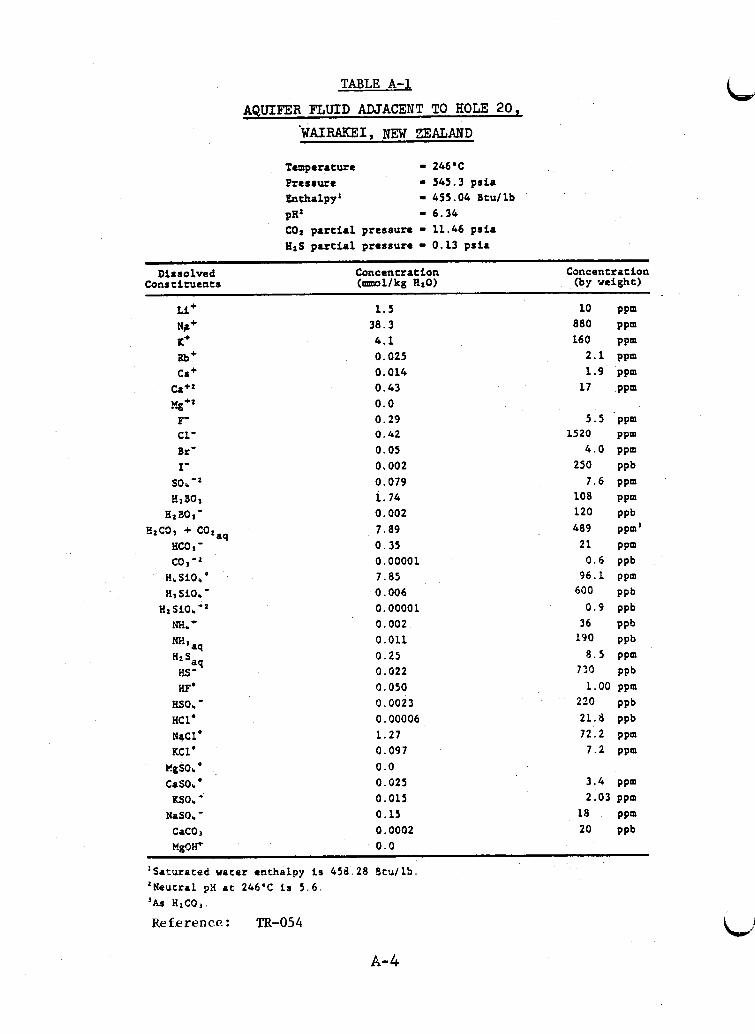
TABLE A - l
AQUIFER F'LUID ADJACENT TO HOLE 20,
Temperature - 246'C Pressure - 565 .3 psia Enthalpy - 455 .04 Btullb PRZ - 6 . 3 4 C02 partial pressure - 11 .46 psia HzS partial pressure - 0.13 psfa
DisroLved Concentration Concentration Constituents ( m l l k g HzO) (by weight)
tL+ 1 .5 10 PPm Nr+ 38 .3 880 ppm I(+ 4.1 160 ppm
2 . 1 ppm Rb+ 0.025 Ca + 0.014 1 . 9 ppm
c a + z 0 .43 17 PPm Y-+Z 0.0
5 . 5 ppm F- 0 . 2 9 c1- 0 . 4 2 1520 ppm Br' 0.05 4 . 0 ppm 1- 0,002 250 ppb
7 .6 ppm BYBOY 1 .76 io8 ppm
Blao,- 0.002 120 ppb 7 . 8 9 489 ppm'
sob-' 0 .079
aq 8zC3, + cot HCO I - 0.35 2 1 PPm co1 0.00001 0 . 6 ppb
9 6 . 1 ppm HI Sf06 - 0 .006 600 ppb
H z S i O * - ' 0.0000 1 0.9 ppb
0.011 190 ppb "3aq 8 . 5 ppm Hn S 0 . 2 5 %a* 0.022 720 ppb
1.00 ppm BO. - 0 .0023 220 ppb HCL' 0.00006 21 .8 ppb NaCl' 1 .27 7 2 . 2 ppm KCl. 0.097 7 . 2 ppm
casob' 0.025 3 . 4 ppm = o b ' 0.015 2.03 ppm
H b S i O b ' 7.85
m* - 0 . 0 0 2 36 PPb
we 0 .050
KlgSOr ' 0.0
NaSO. - 0.15 18 PPm CaCOJ 0 .0002 20 PPb Mgo" 0.0
'Saturated water enthalpy i s 4Sd. 28 Btullb. 'Neutral ptI at 246OC is 5 . 6 .
Reference : TR-054 'AS HzCOI.
A-4
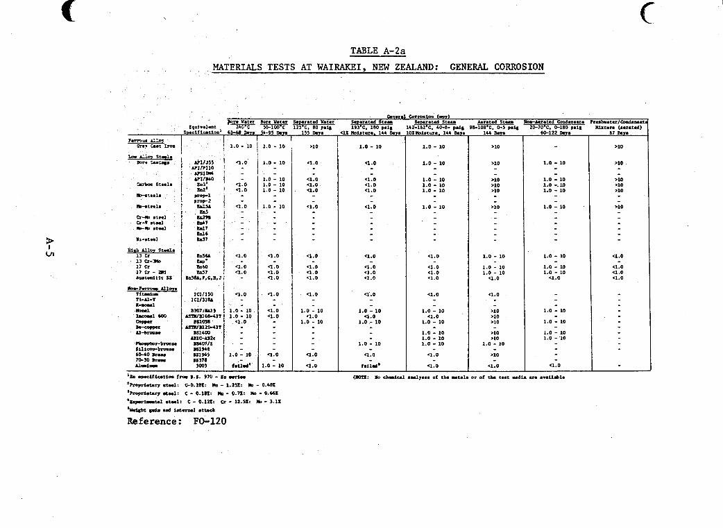
P I
Ln
TABLE A-2a
' 13 Q-k 1: Cr 1 7 c r - m hutdt l t ss
lorrcrrotr AllWS Ti- Ti-Al-T
MATERIALS T E S T S AT WAIRAKEI, NEW ZEALAND: GENERAL CORROSION
6aan.l Corrosion (-1 B n Water &are Water Swarated Water S .rated S t e m SI arsted Steam Aerated S t e n me-Aerated Condamace Ireshrster Qndensat
2L0.C 50-100.C 125'C. 80 psi; 1& 180 psi; 2-1& 40-8- ps1; 9&108*C. 0.3 psu 20-70% 0-180 p . i l IUstnre :aerar.d) Qkisturr. 144 D.Ts lbb b T S 60-122 h Y S 67 h i e
- - - b3-60 l a ~ ~
1.0 - 10
'1.0
e1.0 Q . 0
q1.0
q1.0
-1.0 '1.0
c1.0
1 . 0 - 10 1.0 - 10
< l . O
1.0 - 10
failed'
1.0 - 10
1.0 - 10
1.0 - 10 1.0 - 10 1.0 - 10
1.0 - 10
q . 0
Q.0 '1.0 -1.0
'1.0
- 1
'1.0 '1.0
e1.0
1.0 - 10
'lb srmciflution f r o LS. 970 - '~roprtcum s m : GO.LIJZ: m - 1.251: m - 0.m 'hopriet.ry .toel: c - 0.181: m - 0.71: ISD - 0.661 'xxperiwaul stalt c - 0.1~1: Q - n.sI: m - 3.11
mer-
.Id *d attack
Reference: FO-120
>10
-2.0
c1.0 c1.0 a . 0
< l . O
11.0
a . 0 c1.0 < l . O
c1.0
1.0 - 10 a . 0
1.0 - 10
Q.0
c1.0
1.0 - 10
c1.0 - - c1.0 a . 0 c1.0
a . 0 -
- a . 0
-4.0 < l . O a . 0
-
1.0 - 10 a . 0
1.0 - 10
1.0 - 10
a . 0 -
f.114'
1.0 - 10
1.0 - 10 1.0 - 10 1.0 - 10 1.0 - 10
1.0 - 10
(1.0
c1.0 c1.0 < l . O
e1.0
1.0 - 10 c1.0
1.0 - 10
1.0 - 10 1.0 - 10 1.0 - 10
'1.0
(1.0
>10
1.0 - 10
1.0 - 10 1.0 - 10
a . 0
c1.0
>10 >lo .lo >10 >10
1.0 - 10
>10
a . 0
1.0 - 10
- 1.0 - 10 1.0 -. 10 1.0 - 10
1.0 - 10
1.0 - 10
1.0 - 10 1.0 - 10
c1.0
1.0 - 10
1.0 - 10
1.0 - 10 1.0 - '10
a . 0
>10
.10
- ,>lo >10 >10
.10 -
a . o
a . 0 a . 0 c1.0
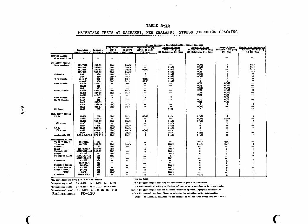
? m
. . . . .... . . . .- - .. . .~. . ~ _ _ . " . . . . . . . " .. . , ~~ -.. .... . . ,
TABLE Pa-2b
MATERIALS TESTS AT WAIRAKEI, NEW ZEALAND: STRESS CORROSION CRACKING
?errow Allom
La Allo? Steels
on, ceet iron
Bore c u i n 6 e
C-St..l.
c-m 8tul.
c-m 8 t d .
ni-Steel
Bish Alloy Steel. 13 R
IC1131M l u l l 5 0
B30721W3 urmlB168-4lT
1SlOM urml120JlT W l 2 0 - 4 1 T
B81400 ADlC-AB2C BS4071. 181948 W1949 B378
Alwe 3003
b c b n l l Wdnas.
-_ C30-31 B96-99 190-92 B68-72
WO BSO B95 MO
c21-22 u 5 M5
C37-39 C27-30 Cl8-19 c48 c53
C3bJ3 CZ8-30 c25-27
-7
C30 C12-28 B60-90
C30 198
M5-94 c28-42 U93-C28 B70-B90
e33 B93-98
a 5 B65-69 B68-77
E83 C38 M7 B54 163 B93 159 M9 B50 n55 -
'18 .pecification fm B.8. 970 - Kn Miem 'Prvpcietary areal: C - 0.282: k - 1.22: No - 0.402 ' m p c i e u r y .t..il c - o.iam IIII - 0.721 m - 0.662 'Experiuntel .teal: c - 0.122: cr - 1 2 . l : m - 3.12
Reference: FO-120
QTlOTAMd 0 -lo ucroecopic cracUn6 or f r u t u r e i n e group of epeciulu I - Mcroewpic creckin6 or fdlurs of one or mre specinuts in group teated
(of) - lo microewpic surface f i u u r u detected by ntal logrephic exnirurion (I) - Microscopic surface fieeuree detected by utal logrephic a n i n a t i o n
(rOn: lo chemical d y e e e of tha u t d e or of tb. test d i e ere eveilable)
c
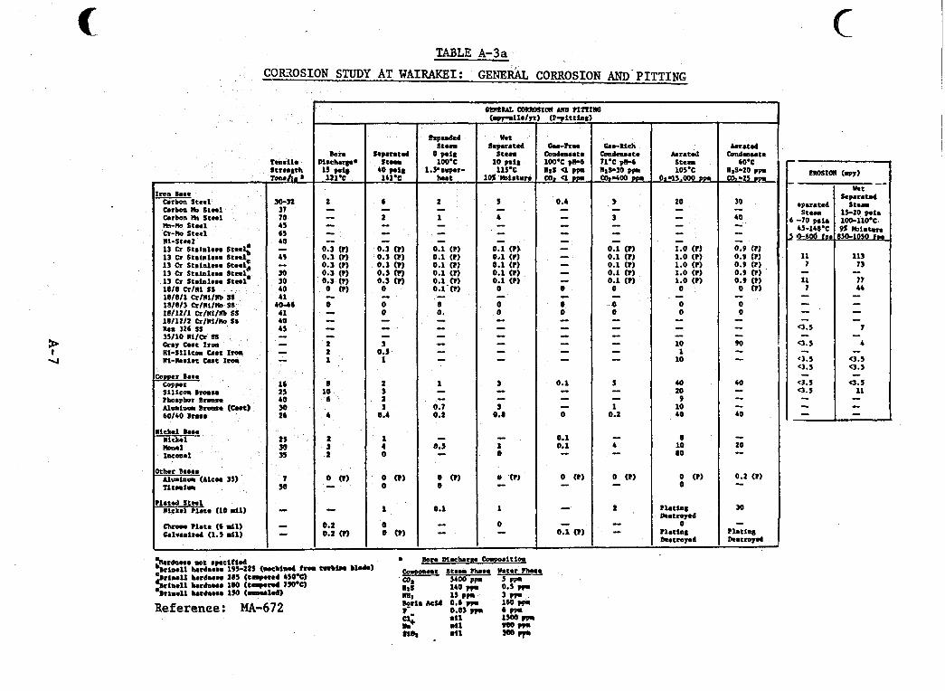
t-
0 (1) 0
09 01 9
09 01 6 OL 09
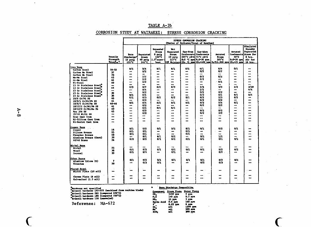
TABLE A-3b CORROSION STUDY AT WAIRAKEI: STRESS CORROSION CRACKING
? 00
rhrr Baael A l w l n u ( A l e 0 0 35) Ti t a n i w
h e e d Steel Nickel Plete (10 m i l )
Chrome ?lata (6 m i l ) Galvanired (1.5 rill
30-32 37 70 45 65 40
43
30 30 40 41
4 0 4 4 1 40 4s
- -
- - - - 1C IS 40 30 26
2s 30 3s
7 so
- - I
Dparatel Steam
LO pal8 141.C
014 012
212 212 212
017 OIL 012 O I L 013 012 014 012 011 012 012
- -
-
- - - 012 011 011 011 012
- 012 012
012 013
- - - -
McXIIIc 1 of sm1
he-xien ondenaote 1.C pW6 rS-30 PPI 0 ~ 6 0 0 DDI
011 012
012 212
216 212 012 013 012 012 01 3 012
012 012
- - -
- - -- -- 011
O I L 011
-
- 011 - 011 012
-- -- -
Referenee: MA-672
P
Aerated S t . P 105.C
)=n.oVo WI
014 012
012
011
31s
012 011 213 012 011 012
012 212
- -
- - - - 012
111 01 1
- -
- 012 012
012 013
- I -
f
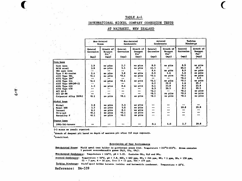
TABLE A-4 INTERNATIONAL NICKEL COMPANY CORROSION TESTS
no p i t s no p i t s no p l t s no pit. no p i t s
--
2.3 5.0 0.1 <O.l co.1
--
AT WAIRAKEI, NEW ZEALAND
capper base
10Ni-SAL-bronze
~~
Nan-Aereted I Condensate Non-Aerated
S teer
General Corrosion
( w )
2.9 3.8
2.4 (0.1
<o. 1
1.3
-- -- -- -- -- --
(0.1
2.8 5.2 0.1
(0.1 (0.1
--
Growth of k e p e s t
P l t ' (wv) --
no p l t s no p i t s
no pice
IK) p i t s
no pit.
-- nu p i t s --
-- -- -- -
no p i t s
Growth of Deepeat
P l t ' b p y )
no p i t a nu p l t n
no p i t s --
no p i t a
no p1 t s -- --
no p i t s -- -- -- no p l t s
no p i t s no p l t s no p i t s no p i t s no p i t s
--
Aerated Condensate
General Corrosion
(UPY)
8.0 14.3 8.4 0.9
C 0 . l
(0.1 0.2 0.1 0 . 3
co.1 CO.1 (0.1
--
-- -- -- -- --
0.1
Growth of Deepest P l t l (wy)
IIQ pit. -- no p i t a
4.6 no pit.
no p i t s 29.8 23.8 20.5
no p l t s
--
-- . 110 p i t s
-- -- -- -- --
4.0
Turbine Dimclmr8a
General Corrosion
( 3 Y 1
8.9 10.5
8.9 4.6
co.1 co.1 CO.1 1.6 0.5 0.1
< O . l co.1 c0.1
-- 10.8 I - --
1.7
Ctat th of Deepest P i t h (w)
no pit. 29.7 no pit. no pit. no pit.
6.0 M p i t s
29.7 23.8 20.5 M p i t a no pit. no pit.
-- 29.8 -- u --
29.8
(-) means no r e s u l t reported.
'Growth of deepest p i t based on depth o f nnxlmur p i t a f t e r 552 deye exposure. 'Sena it I sed.
Dcncrlptlon of Test h iv i runwnts
Won-Aerated Steam: Field spool test holder I n geotltermal s t e a n l l n e . Temperature - 147*C-l53'C. Steam eontaiaa
Non-Arrnted Condensate:
-- Aerated Cornlenscite:
Ttrrblw Dlacltarwel
1 percent nuncondensable Bases (I laS. CO'. CII.).
Temperature - 116%. pH - 5.25. Cuntalna Cot. HIS and Nllr. feml'ctrclttira - 50%. pll - 7.8, IICOS - 662 ppu. Nlla - 216 ppm. )(os C1 - 7 ppu. 1) - 18 ppu, f r r u S - 13 ~ ~ I I I . TIIS.- 119 p p ~ .
Pield'upuul Imlder brtweeii t u rb ine r ~ i d b n r o m t r l c cudenmar.
1 ppm, SO4 - 159 p p ,
Tewrro ture - 52°C.
Reference: BA-539
A, 1.3.1 General Corrosion
Because of chemical impurities in geo- thermal steam, particularly chlorides, "2s and CO2, corrosion rates of common engineering alloys are usually higher than those encountered under similar conditions of temperature and pressure in clean boiler plant steam.
Corrosion of most common engineering alloys in air-free geothermal media, with the exception of some copper alloys, is low enough to insure adequate service life. Mild steel is adequate for air-free service if a moderate corrosion allowance is made.
Aeration of geothermal media drastically increases (ten-fold or more) the corro- sion of most engineering alloys with the exceptions of austenitic stainless steels (especially those containing molybdenum), titanium, and chromium plated steels. Galvanizing is unsuccessful in aerated geothermal media.
Corrosion rates of most alloys in bore water at 250°C are 19w cornpared to those in lower temperature media. Pitting is characteristically absent in bore water at 250°C.
A- 10
bd A. 1.3.2 Erosion-Corrosion
Empirical tests at Wairakei indicated that the follow- ing steels have sufficient resistance to erosion-corrosion by water droplets in steam (containing 9% moisture) at 900 fps (ex- haust-end blading environment) to serve as turbine blading: 13 Cr, 18/8/1 Cr-Ni-Cb, 18/12/1 Cr-Ni-Cb, 18/8/3 Cr-Ni-Mo, "Rex 326," 35/10 Ni-Cr. static corrosion resistance and not to hardness as is often as- sumed (MA-672).
Erosion-corrosion resistance is directly related to
A.1.3.3 Stress Corrosion Cracktng (SCC) of Austenitic Stainless Steels
Tests indicate that even under conditions of high stress, austenitic stainless steels are not susceptible to SCC in oxygen-free media. In the presence of dissolved oxygen, the lower temperature and chloride concentration limits appear to be 50°C and 5 ppm C1-. There appears to be no lower critical stress limit for SCC.
A.1.3.4 Hydrogen Sulfide Effects
At Wairakei the following observations were made con- cerning sulfide stress cracking (SSC) :
Medium.and high strength steels are susceptible to SSC in geothermal media up to at least 190°C.
Mild steels and low strength alloys resist SSC even under severe constant deformation tests. The highest safe
A-11 w
t e n s i l e s t rength appears t o be 88 ksi* L+ f o r carbon and low a l loy steels and 110-120 k s i f o r high chromium a l loys .
Suscep t ib i l i t y t o SSC i s of ten r e l a t ed t o hardness r a the r than y i e ld s t rength (HU-200). 13 C r turbine blading was r e s i s t a n t a t a hardness below Br ine l l 180 (Rc-8) and vulnerable above Br ine l l 190 (Rc-11).
Delayed f r ac tu re can occur i n severely notched low s t rength al loys exposed t o cold H2S-bearing condensate a t s t rengths below 88 k s i .
H2S-bearing dry steam i s innocuous.
SSC of highly suscept ible steels did not occur i n bore water a t 240°C but did occur i n the same water a t 50°C.
Bl i s te r ing has been observed i n some low strength a l loys .
Hydrogen infusion rates decrease t o very low values a f t e r two to three weeks exposure above lOO"C, probably because of corrosion f i l m s .
Permeation rate can be g rea t ly reduced by surface coatings such as Apexior No. 1 paint or by chemically formed Fe304 coat ings.
*ksi = thousand pounds p e r square inch.
Ld A- 12
There is an inverse re la t ionship between infusion r a t e and temperature i n bore water due t o the formation of magnetite a t higher temperatures. The magnetite on the i ron surface appears to impose a b a r r i e r (equilibrium and/or k ine t ic ) which reduces the hydrogen concentration below the corroding surface (FO-123).
A.1.4 Plant Experience a t Wairakei
I
Overall plant experience (MA-668), erosion and thermal s t r e s s of production casings (SM-160), and w e l l casing problems (FO-119) have been documented f o r the Wairakei power p lan t .
A. 1 .4 .1 Bore Casings and Wellhead Equipment
Conventional low strength API grades 5-55 and H-40 pro- duction casings have been used. bes t compromise between s t rength and suscep t ib i l i t y t o s u l f i d e s t r e s s cracking. In te rna l corrosion has been minimal. Erosion by e jec ted sand has been control led by s lo t t ed production l i n e r s .
5 - 5 5 has been adopted as the
External corrosion of surface casings has been severe near the surface where aerated ground water contacts the casings. Multiple casing with careful cementing of the annul i has con- t r o l l e d t h i s problem.
Thermal s t r e s s i s severe. It can exceed 60 k s i and may cause mechanical f a i l u r e o f l o w s t rength casing a l loys . High s t rength a l loys (N-80 and above) should be avoided because of su l f ide s t r e s s cracking.
'French s t e e l APS 10M4 has shown promise i n laboratory tests a t The medium s t rength su l f ide r e s i s t a n t
i I) A-13
Wairakei (MA-682). Thermal stress may be a l l ev ia t ed by careful cementing to avoid unsupported regions. Careful cementing a l s o prevents the formation of trapped w a t e r pockets which w i l l col- lapse the casing once production i s begun. Keeping bores flow- ing after i n i t i a l "blow-in" w i l l reduce thermal stress and pre- vent the formation of cold, nonaerated HzS-bearing condensate--the main source of s u l f i d e stress cracking.
Wellhead equipment of low s t rength steels with s t a in - less steel valve t r i m has performed s a t i s f a c t o r i l y . protectj.on (paint o r cladding) against corrosion by airborne chlor ide sprays and steam i s required. of carbon steel are sa t i s f ac to ry i f the media remains a i r free. A i r inleakage must be avoided.
External
Transmission pipel ines
A.1.4 .2 Turbines
The turbines a t Wairakei are made of conventional t u r - bine construct ion materials (cast steel casings, carbon steel ro to r s , 13 C r s t e e l blades, shrouds, and lacings) heat t rea ted t o a low s t rength condition. i c a l l y a t tached r a t h e r than brazed t o avoid loca l hardening of the 13 C r s teel . The rivets are annealed. Care i s used t o seal the j o i n t s i n low pressure casing as thoroughly as possible t o avoid a i r ingress and accelerated corrosion by aerated media. Blade ve loc i t i e s are l imited t o 900 fps and moisture t o 9 per- cent t o avoid excessive blade corrosion. These turbines have given good service.
The shrouds and lacings are mechan-
A. 1.4.3 Elec t r i ca l Equipment
Atmospheric H,S tarnishes copper and si lver contacts . Erosion-corrosion of copper contacts exposed t o H2S is rapid. A t Wairakei, s i lver contacts are replaced i n c r i t i ca l equipment
1 A - 1 4 :
L4 with platinum contacts . a t The Geysers i n Cal i fornia .
This problem has been s tudied extensively t
Their r e s u l t s are given i n Section 1 i A.3.4. 1
I
I A . 2 CORROSION AT THE CERRO PRTETO GEOTHERMAL POWER PLANT
I I The Cerro Pr ie to geothermal power plant has operated
i has operated continuously except f o r scheduled downtimes. The
!
I since 1973. In s p i t e of some ser ious material problems, the p lan t
I Cerro P r i e to pro jec t provides operating experience and corrosion i I tes t da ta from a s ingle-f lash, liquid-dominated system. The simi-
l a r i t y between Cerro P r i e to geothermal'media (Table A-5) and the f l u i d s of East Mesa, Ho l tv i l l e , and Heber, Cal i fornia indicates t h a t corrosion phenomena may be similar a t a l l si tes, and Cerro P r i e to experience w i l l a id i n the design of fu ture power p lan ts .
A . 2 . 1 Sys t e m Description
l
The Cerro Pr ie to geothermal resource i s liquid-dominated. Surface manifestations cover an area of about 30 square kilometers. The u t i l i z a t i o n mode i s s ingle-f lash (bore-flashing). A s of 1976, 53 deep w e l l s had been d r i l l e d i n t h i s area with depths of 70Om t o 200Om. F l o w i s obtained through p r e s l o t t e d or gun perforated casings a f t e r cementing the production casing, except the bottom 150m to 30Om, where hot strata a r e located. High enthalpy water a t 275-320°C flows through the perforated casing and i s conducted t o the surface through the 7 5/8" production casing (SC-448). As the w a t e r ascends through the production casing, the hydrostat ic pressure drops and the water p a r t i a l l y f lashes t o steam. The flow through the w e l l t r e e i s a two-phase f l u i d containing from 20 t o 40 weight percent steam. The f l u i d i s passed through a Webre type cent r i fuga l separator a t t he wellhead (SC-448) and through a secondary separator a t the power p lan t (GE-119). separated water i s sent t o an evaporating pond (SC-448).
The
A-15
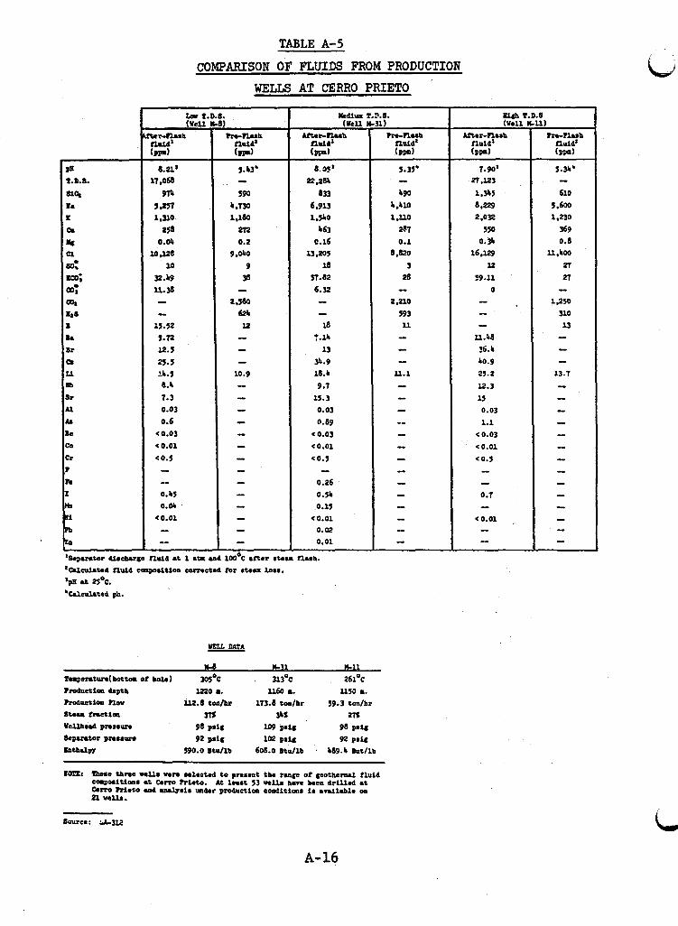
TABLE A-5
-
i I I
I i I 1
I I
,
I I
I
1 I
I
i i 1
I
COMPAFUSON OF FLUIDS FROM PRODUCTION
WELLS AT CERRO P R I E T O
M u m ( U C U
Uter-ILUh npid l (ppn)
8.35' 22.28
633 6.913
b63 0.16
l3.205 18
5T.82 6.32
1 J b O
- - 18
7.14 13
34.9 18.b 9.1
15.3 0.03 0.89
< 0.03 co.01 c0.5 -
0.26 0.54 0.15
(0.01 0.02 0.01
Source: &3K
A- 16
7.90' n .K3 1,315 6,229 2.032
550 0.35
16 e l 2 9 K
59.11 0 - -
U.b8 36.4 L0.9 25.2
l2.3 15 0.03
1.1 < 0.03 co.01 c 0.5 - -
0.7 - co.01 , -
I I ,
20 t o 80 tons/ho lr of s t t 100 ps ig are obtained from each wel l . A s of 1976, 13 w e l l s provide steam t o maintain two u n i t s of 3 7 . 5 MW each, a t f u l l load, a t a steam rate of 9.4 kg/&lh (SC-448).
A . 2 . 2 Cerro P r i e to Geothermal Fluid
Based on i so topic analyses, the Cerro Pr ie to geothermal
The production s t ra ta i s sandstone with a lava overlay. f l u i d i s meteoric and i s derived mainly from the Colorado River (SC-448). The geothermal f l u i d i s saturated with s i l i c a (from quartz) a t the temperatures and pressure present i n the production strata (SC-448).
w e l l s are given i n Table A-5. The three analyses (from 115 pre- sented i n LA-312) show the range of br ine compositions a t Cerro Pr ie to .
Analyses of geothermal f l u i d from three production
A . 2 . 3 Corrosion Tests a t Cerro Pr ie to
From 1969 t o 1970 a corrosion test program w a s performed j o i n t l y by the Comision Federal de Electr ic idad of Mexico and Tokyo Shibaura Company (Toshiba) of Japan. confirm the corrosion res i s tance of previously selected materials t o be used f o r construct ion of the power p lan t which w a s ordered i n 1968.
The purpose w a s t o
Coupons were used i n the general corrosion test . The stress corrosion specimens were U-bend s t r i p s s t ressed beyond the y i e ld point and retained under stress by a b o l t . The erosion- corrosion specimens were cyl inders 6 c m long and 1 e m i n diamter (GE-119). The r e s u l t s of the tests and d e t a i l s of test condi- t ions a re presented i n Table A-6. i a l s t e s t ed are i n Table A-7. No d i s t inc t ion w a s made between stress corrosion cracking and su l f ide stress cracking.
Compositions and uses of mater-
A-17
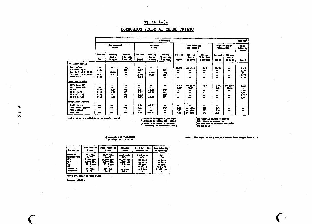
c
TABLE A-6a CORROSION STUDY AT CERRO P R I E T O
S t e n
c 'I
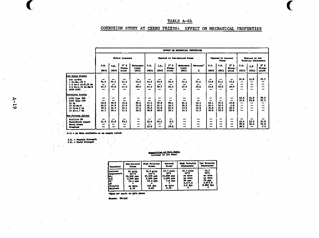
TABLE A-6b CORROSION STUDY AT CERRO PRIETO: EFFECT ON MECHANICAL PROPERTIES
I
I Lfon Capwun hp.d to k r a t d S t e n
- 11.1
11.4 - - - I
21.3 2b.S 13.9 14.s
- I
s3.9 43.1
S1.3 50.7 - - - - - - I -
47.3 3e.1 bS.3 11.3 39.0 24.0 30.8 10.8
13.S
28.4 - - - 2b.l 31.0 17.1 1b.S
* I
- - - - 41.0 39.9 bS.2 54.) 39.3 24.3 31.7 1.1
- - I l i j If 19.9
15.4 15.2
10.) - n.r I n.r
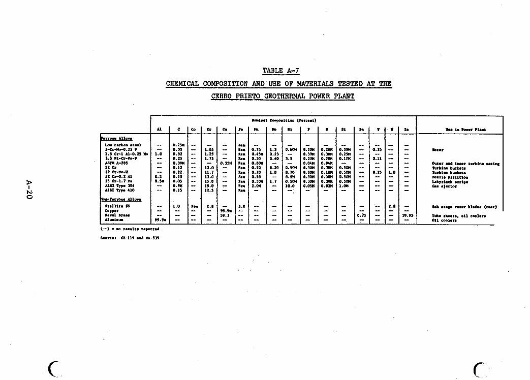
..I. _ _ ... .. , . , . .- ..I.__.I" _ _ ._". . .. .- . ... , . .. ,. . . . . . -. .. . . .. . . . . - . . . . . . ... ._ . , . , .
1
- 0.2011 0 . m 0.2on 0.0411 0.m o,zon 0 . m 0.3011 0.0% -
-- - -
c.
8 si sm
- - I
0.2011 O.3OII - 0 . m 0.2% - 0.2on 0.lffl - omn - - 0.m 0.5ffl -- ~.ion ~ . s o n - 0.30~ o . 5 ~ - 0.m 0.5011 - 0.0311 i.on - - I
- - - - - -- - 0.71 I -. -
l-cr-0-0.25 v 1 .5 Cr-1 1s-0.25 WI 3.5 Ill-Cr-)&V UM A-285
12 CfWD-w I2 cr-o.2 Al 15 h-1.7 )(o A I S 1 Typa 304 AIS1 Typm 410
kvrl Ira.. A l U h U
0 . m 0.30 0.32 0.25 0.3W
I 0.12 I 0.22 I 0.25
0.05 I 0.811 0.15
I 1.0 1 -- I -
TABLE A-7
- - - 1.05 -- 1.25 -- 1.75 - - -- 12.0 -- 11.7 -- 13.0 - 15.0 - 19.0 - 12.5
Rem 2.8 I -_ - - - - -_
CHEMICAL COMPOSITION AND USE OF MATERIALS TESTED AT THE
CERRO P R I E M GEOTHERMAL POWER PLANT
AI C Co Cr
I I I
I I:
btor
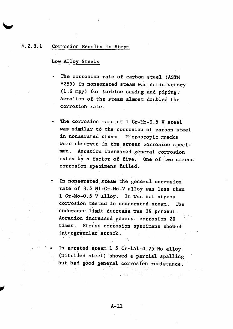
i
I
I V I
A. 2.3.1 Corrosion Results i n Steam
Low Alloy Steels
The corrosion rate of carbon steel (ASTM A285) i n nonaerated steam w a s s a t i s f ac to ry (1.6 mpy) for turbine casing and piping. Aeration of t h e steam almost doubled the corrosion rate.
The corrosion rate of 1 Cr-Mo-0.5 V steel w a s s i m i l a r t o the corrosion of carbon steel i n nonaerated steam. Microscopic cracks were observed i n the stress corrosion speci- men. Aeration increased general corrosion rates by a fac tor of f i ve . corrosion specimens f a i l ed .
One of two stress
I n nonaerated steam the general corrosion rate of 3.5 Ni-Cr-Mo-V a l loy w a s less than 1 Cr-Mo-0.5 V a l loy . corrosion tested i n nonaerated steam. The endurance l i m i t decrease w a s 39 percent . Aeration increased general corrosion 20 t i m e s . S t ress corrosion specimens showed intergranular a t t ack .
It w a s not stress
In aerated steam 1 .5 Cr-1A1-0.25 Mo a l loy (n i t r ided s t e e l ) showed a p a r t i a l spa l l ing but had good general corrosion res i s tance .
A-21
i
In nonaerated steam aluminum w a s not corroded. Aeration of steam l e d t o p i t t i n g i n excess of 100 mpy.
S ta in less Steels
In nonaerated steam, 1 2 C r a l l oy (used f o r turbine buckets) had a very low (<0.5 mpy) general corrosion rate. p i t t i n g . It w a s not suscept ible t o s t r e s s corrosion cracking. Resistance t o erosion- corrosion was acceptable. There w a s no change i n t e n s i l e s t rength, only a s l i g h t decrease i n y ie ld s t rength , and a decrease i n endurance l i m i t (15 t o 19 percent) . Aeration increased general corrosion ten t i m e s and p i t t i n g 70 t i m e s . the stress corrosion specimen.
There was s l i g h t
Microscopic cracks were observed on
In nonaerated steam 1 2 Cr-Mo-W steel w a s com- parable t o 1 2 C r i n terms of general corrosion, p i t t i n g , and stress corrosion cracking. corrosion res i s tance w a s b e t t e r than 1 2 C r s teel . similar to 1 2 C r s teel . Aeration caused a ten-fold increase i n general corrosion, a seventy-fold increase i n p i t t i n g , and intergran- u l a r corrosion of t he stress corrosion specimen.
Erosion-
Changes i n mechanical propert ies w e r e
In nonaerated steam, 12 Cr-0.2 A 1 a l l o y (used f o r nozzle pa r t i t i ons ) had a low general cor- rosion ra te . No p i t t i n g was reported. The a l l o y w a s r e s i s t a n t t o stress corrosion and erosion-corrosion res i s tance w a s s imilar t o
A-22
1 2 C r s teel . Aeration increased general cor- rosion t o a lesser degree than f o r 1 2 CR-Mo-W steel , and no p i t t i n g was reported. 15 Cr-1.7 Mo steel w a s no t suscept ible t o stress corrosion i n aerated steam. Erosion-corrosion res i s tance w a s qu i te good. s t rength w e r e not as severe as f o r 1 2 Cr-Mo-W.
Changes i n t e n s i l e and y i e ld
A.2.3.2 Corrosion Results i n Condensate*
The corrosion ra te i n high veloci ty (1.5 fps) condensate w a s excessive f o r materials commonly used i n heat exchangers (deoxidized copper, naval brass , and carbon steel) .
The p i t t i n g rate of aluminum w a s g rea te r than 100 mpy.
AISI Type 410 steel p i t s a t a rate of more than 30 mpy. of AISI Type 304.
General corrosion w a s ten t i m e s t h a t
A I S I type 304 steel showed the bes t corrosion res i s tance (of t he s t a i n l e s s steels tes ted) i n condensate. low. P i t t i n g and stress corrosion w e r e not detected.
Plant experience indicated t h a t AISI Type 304 heat exchanger tubing would not serve i n aerated condensate. Titanium tubes have given good service.
Uniform corrosion w a s very
*It w a s n o t . c l e a r whether o r not the condensate used i n the tests w a s aerated and the H2S concentration w a s no t given. w a s about 7.
The pH
A-23
. Epoxy coatings cured a t high temperature showed no de ter iora t ion i n low ve loc i ty condensate a f t e r 150 days of exposure.
A.2.4 ODeratine ExDerience a t Cerro P r i e to
The successful operation of t he Cerro Pr ie to geothez- m a l power plant has provided valuable materials experience tha t may be used i n the design of U.S. p lan t s . geothermal f lu ids i n southern Cal i fornia makes the Cerro P r i e to data pa r t i cu la r ly useful .
The s i m i l a r i t y of
Carbon and low a l loy steels have served s a t i s f a c t o r i l y i n nonaerated l i qu id o r steam. When oxygen w a s introduced t o the geothermal media, carbon steel w a s severely corroded. Stain- less steels, t i tanium, o r nonmetallic materials are required i n aerated steams.
Materials experience i n the various pa r t s of the power plant i s discussed below.
A. 2.4.1 Bore Casines and Surface EauiDment
Several problems and two blowouts have occurred due t o the rupture o r col lapse of bore casings a t Cerro P r i e to . It i s not known when and t o what extent s t r e s s corrosion, su l f ide stress cracking, galvanic corrosion, j o i n t o r casing erosion or excess stress have been involved because the broken casings could not be recovered (GE-119).
A f t e r geothermal wel ls have been completed, they remain ou t of production u n t i l t h e i r temperature, which decreased during d r i l l i n g , .rises again and f a c i l i t a t e s t h e i r ac t iva t ion . During t h i s t i m e , i n t e rna l pipe w a l l s of some of t he w e l l s have been
A-24
es si at tacked by elevated concentrations of H 2 S . Reservoir ga :h
H 2 S becomes concentrated as C O n and H2S flow i n t o a w e l l out of production and cause the w a t e r level t o o s c i l l a t e s ign i f icant ly . i n t he co ldes t area near the surface and a t tacks the pipe. The extent of damage has not been measured, but when a w e l l i s acti- vated, the i n i t i a l discharge of w a t e r has a higher i ron su l f ide content (ME-S-250). Sulf ide stress cracking i s a l s o a hazard under these conditions. act ivated as soon as possible a f t e r completion.
To minimize these problems, w e l l s are
Sulf ide stress cracking appears t o have occurred once under condi t ions s i m i l a r t o those described above. Well M-5, cased with A P I grade H-40 steel , f a i l e d when cold water w a s in- jec ted during repair operations (GE-119). This behavior corre- sponds t o t h a t a t Wairakei where casing steels H40 and K55 have f a i l e d rapidly i n cold H2S-bearing condensate (FO-120, MA-682, SM-160, FO-119).
Leaks of hydrothermal f l u i d s between w e l l casings o r between casings and the w a l l s of the hole lead t o degradation of t he cement and to expansion and contract ion of the w e l l casing. Small f r ac tu re s allow the passage of geothermal f l u i d s from the production s t ra ta a t the bottom of the w e l l up t o the surface. The r e s u l t i s bubbling and escape of gases and steam promoting corrosion on t h e outs ide of the w e l l casing. This i s prevented through intensive maintenance with temperature r e s i s t a n t pa in ts o r by adding high temperature lubr icants (ME-S-250).
Galvanic coupling of production pipe with packing flanges has promoted crevice corrosion of the casing a t the w e l l - head. tact of the pipes a t the surface and by el iminat ing the packing f langes. lubr ica t ing greases (ME-S-250, GE-119).
This has been corrected by preventing metal-to-metal con-
The space is f i l l e d with cement o r high temperature
A-25
P i t t i n g and general corrosion of the i n t e r i o r s of mild
Erosion-corrosion has been frequent ly ob- steel surface pipes carrying nonaerated geothermal media have been " insignif icant ." served a t surface i n s t a l l a t i o n s where there i s a sand-water-steam flow at high ve loc i ty (GE-119).
Purge leaks and atmospheric discharges occasionally form sa l t deposi ts on valves, Christmas trees, and pipes . The surface corrosion t h a t r e s u l t s i s control led by constant scraping and appl icat ion of protect ive paints .
The Cerro P r i e to discharge w a s i n i t i a l l y passed through steel vertical s i lencers . The combination of geothermal media and atmospheric \oxygen caused severe corrosion of the s t e e l . problem w a s eliminated by construct ing spec ia l s i l ence r s with concrete bases and towers of wood o r f iberg lass (ME-S-250).
This
There have been few corrosion problems i n the conduc- t i on l i n e s f o r the separated hot water (16O-18O0C) which t rans- po r t t he br ine from the separators t o the evaporating pond. ever, there has been a case i n which severe scal ing w a s accompanied by corrosion. Interrupt ions i n the flow exposed the i n t e r n a l w a l l s of t he pipe t o combined a t tack by sal ts and atmospheric oxygen. If the l i n e s are kept h o t , there i s almost no i n t e r n a l corrosion. Lines are not present ly insulated, and some external a t tack by t h e sa l t spray and oxygen r e s u l t s (ME-S-250).
How-
A . 2 . 4 . 2 Steam Conduction System
Carbon-steel steam conduction l i n e s normally s u f f e r a s l i g h t i n t e rna l a t tack and become coated with an i ron su l f ide fi lm. The f i l m i s usual ly not a problem, but occasionally the f i lm dislodges and blocks steam traps o r en ters the turbine. Steam traps require intensive maintenance t o prevent and clear
A-26
w blockage by i ron su l f ide f lakes . The problem has been somewhat
of the steam t raps (ME-S-250).
, , remedied by subs t i t u t ing continuous condensate purges f o r most 1
I A.2.4.3 Turbines I
During the f i r s t two years of operation, the turbines w e r e inspected twice. There w a s no observed corrosion o r crack- ing of the turbine buckets (12Crrsteel) . A t the s i x t h s tage of blades, t he S t e l l i t e No. 6 facings were i n "very good condi- t i o n , " with only s l i g h t erosion of the s i lver used to solder the facings t o t h e 1 2 C r s teel blades (GE-119). w a s the scal ing of s i l i c a i n the f i r s t s tage nozzles and buckets (GE-119, SC-448). This problem w a s due t o the poor separat ion of water and steam i n the wellhead and secondary separators , allowing carryover of droplets supersaturated with s i l i c a (Si02) and calcium carbonate (SC-448).
The major pzoblem
. A f t e r two years of operat ion, improved steam separators were i n s t a l l e d t o give 99.99% qua l i ty steam, The service cycle has been extended t o 18 months, and a two-year cycle i s possible (ME-S-250).
I
The ro to r and 1 2 C r turbine buckets have shown only s l i g h t a t t ack after four years of operation. t i on rate i s due t o erosion from: (a) water drople t s , (b) carry- over of i ron s u l f i d e p a r t i c l e s i n the steam, o r (c) sand b l a s t ing car r ied out during preventive maintenance t o e l iminate the sca l e
s l i g h t l y more accentuated i n seals where steam i s mixed with geo- thermal gases and atmospheric oxygen (ME-S-250).
Their highest a t t r i -
a which i s regular ly deposited during operation. Corrosion i s
I
I W ~
A-27.
A. .4.4 Cooling Water System
The major corrosion problems a t Cerro P r i e to have been i n t h e cooling w a t e r system. The cooling w a t e r i s aerated steam condensate containing H2S, C 0 2 , N H 3 , chlor ides , other impuri t ies , and su l f ide-oxidizing bac ter ia .
Extensive corrosion occurred o r ig ina l ly on the water s ide of the aluminum tubes i n the heat exchangers of t he o i l cooling system. A large percentage w a s perforated i n 15 days of operation, and a l l showed s igns of p i t t i n g . replaced by Type 304 tubes, and some of these w e r e a l so perfor- a ted a f t e r several months. The problem i s now control led by draining and drying the tubes when the equipment is out of oper- a t ion . Bacterial growth, which promotes the p i t t i n g , i s accel- erated when the w a t e r i s not flowing. fo r use i n the next un i t (ME-S-250).
The tubes w e r e
Titanium tubing i s planned
Original ly the tubes i n the heat exchanger of the hydro- gen cooling system of the generator w e r e aluminum. These tubes w e r e severely p i t t e d , but w e r e not perforated because the w a l l s were thicker . They w e r e replaced with t i tanium tubes, and there has been no detectable corrosion i n four years (ME-S-250).
The barometric condenser i s the d i r e c t contact type where cooled condensate containing oxygen i s sprayed i n t o the steam. coating on the upper p a r t and clad with Type 304 on the bottom. Water removes the protect ive coating i n some areas, and a t t ack on the carbon steel w a l l s occurs. There has been no corrosion through the s t a i n l e s s steel layer . Condensers f o r fu tu re u n i t s w i l l be c lad with Type 316. The gas e j ec to r contains some car- bon steel tubes which corrode due to the steam, gases , and oxy- gen.
The condenser i s carbon steel covered with an epoxy-
The chimneys used f o r high a l t i t u d e gas discharge are
A-28
f iberg lass and have performed very w e l l (ME-S-250). legs of t h e secondary condenser were o r ig ina l ly carbon s teel . suffered severe corrosive a t tack and were destroyed i n &o years . The problem w a s solved when they w e r e replaced with f iberg las tub- ing.
The barometr .c They
Fiberglass or Type 316 i s planned fo r use i n fu ture u n i t s (ME-S-250).
The carbon steel valves which handle the cooling w a t e r have suffered severe a t tack . of Type 316 and an epoxy coating.
They are now protected with a layer
Closed concrete channels are used f o r conducting cooling water between the condenser and cooling tower. were o r ig ina l ly protected with a coal t a r epoxy. After two years of operat ion, loosening of the epoxy coating and a t tack of the concrete i n the upper p a r t of the channel w e r e noted. The a t tack had become so extensive a f t e r four years t h a t the cement w a s degraded, and sand and gravel were dislodged. Repairs w e r e made, and the concrete was protected by PVC covers.
These channels
The combination of H 2 S , steam, and anaerobic bac te r i a caused degradation i n the concrete channel ce i l i ngs i n a zone with almost no a i r . Concrete below the w a t e r l i n e w a s no t a t tacked because the w a t e r is t rea ted with biocides t o control bac te r ia . Some of the bac ter ia found i n t h e system oxidize H2S t o H2S04, r e su l t i ng i n low values t h a t lead t o degradation. Future in- s t a l l a t i o n s a t Cerro Pr ie to w i l l prevent degradation of t he con- crete on channel ce i l i ngs by flooding o r i n s t a l l i n g PVC plate coverings.
During four years of operat ion, wood i n the cooling tower has degraded s l i g h t l y i n the upper p a r t of the spray zone and i n the region of t he water level. supports and ven t i l a t ion motors are carbon steel protected with
Parts of the transmission
A-29
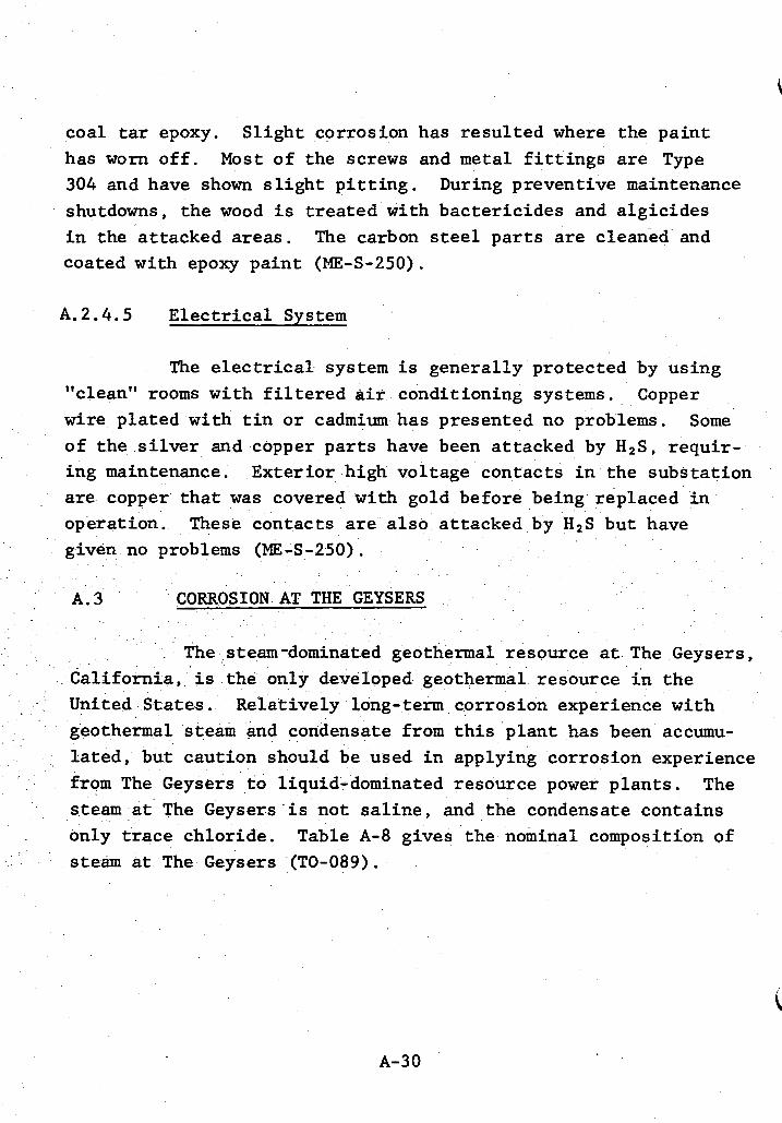
coal tar epoxy. S l igh t corrosion has resu l ted where the pa in t has worn o f f . Most of the screws and metal f i t t i n g s are Type 304 and have shown s l i g h t p i t t i n g . shutdowns, the wood is t rea ted with bacter ic ides and a lg ic ides i n the at tacked areas. The carbon steel p a r t s are cleaned and coated with epoxy pa in t (ME-S-250).
During preventive maintenance
A.2.4.5 Elec t r i ca l System
The e l e c t r i c a l system i s general ly protected by using "clean" rooms with f i l t e r e d a i r conditioning systems. Copper w i r e p la ted with t i n o r cadmium has presented no problems. Some of the si lver and copper p a r t s have been at tacked by H2S, requir- ing maintenance. are copper t h a t w a s covered with gold before being replaced i n operation. given no problems (ME-S-250).
Exter ior high voltage contacts i n the substat ion
These contacts are a l so at tacked by H2S but have
A.3 CORROSION AT THE GEYSERS
The steam-dominated geothermal resource a t The Geysers, Cal i fornia , i s the only developed geothermal resource i n the United States. geothermal steam and condensate from t h i s p lan t has been accumu- l a t ed , but caution should be used i n applying corrosion experience from The Geysers t o liquid-dominated resource power p lan ts . The
Relat ively long-term corrosion experience with
steam a t The Geysers i s not saline, and the condensate contains only t r ace chlor ide. steam a t The Geysers (TO-089).
, Table A-8 gives the nominal composition of
A-30
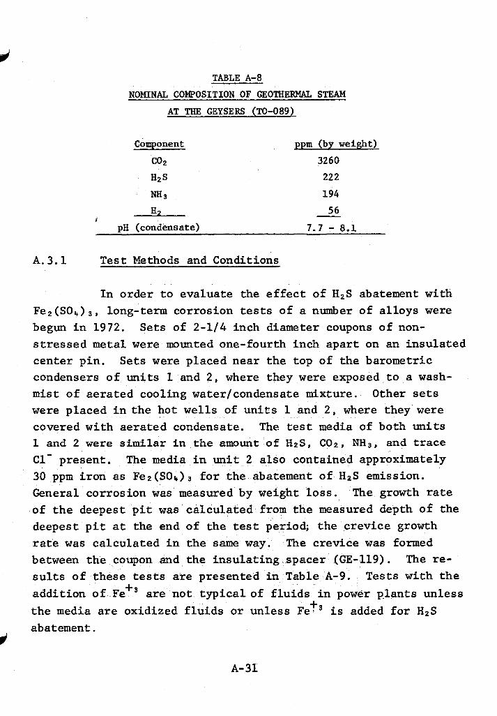
TABLE A-8
NOMINAL COMPOSITION OF GEOTHERMAL STEAM
AT THE GEYSERS (TO-089)
Component p p m (by weight)
co2 3260 H2S 222 "3 194
56 H2 - I pH (condensate) 7 . 7 - 8 . 1
A. 3 .1 T e s t Methods and Conditions
I n order t o evaluate the e f f e c t of H2S abatement with Fe2(S04)3, long-term corrosion tests of a number of a l loys w e r e begun i n 1972. Sets of 2-1/4 inch diameter coupons of non- s t r e s sed m e t a l w e r e mounted one-fourth inch apar t on an insulated center pin. condensers of units 1 and 2 , where they w e r e exposed t o a wash- m i s t of aerated cooling water/condensate mixture. were placed i n the hot w e l l s of u n i t s 1 and 2 , where they w e r e covered with aerated condensate. The t e s t media of both u n i t s I and 2 w e r e similar in the amount of HzS, CO2, N H 3 , and trace C1- present , The media i n u n i t 2 a lso contained approximately 30 ppm i ron as Fez(S01,)~ f o r the abatement of H 2 S emission. General corrosion was measured by weight loss . of t h e deepest p i t w a s calculated from t h e measured depth of the deepest p i t a t the end of the test period; the crevice growth ra te w a s calculated i n the same way. The crevice w a s formed between the coupon and the insu la t ing spacer (GE-119). The re- s u l t s of these tests are presented i n Table A-9. Tests with t h e addi t ion of Fe+3 are not typ ica l of f l u i d s i n power p-lants unless the media are oxidized f l u i d s o r unless Fet3 i s added f o r H2S abatement.
Sets were placed near the top of the barometric
Other sets
The growth rate
A-31
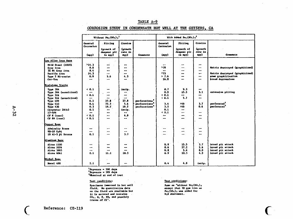
TABLE A-9 CORROSION STUDY IN CONDENSATE HOT WELL AT THE GEYSERS, CA
1 w ru
G
w Alloy Iror Base Hild Steal (1010) Cruy lrm 32 W l Gray Iron Ductlle Iron Type 2 N1-res4ut Cor-Tan
rrlnleas Steeln
Type 304 Type 304 (umsl t lzed) Type 316 Type 316 (aensitlzed) Type 409 Type 410 TYP. 430 Carpenter 2Wb3 1 7 - 4 ~ ~ CF 8 (cast) CP 8M (cant)
*Der Base Admiralty Braas 90-10 CuNI 10 Al-5 pl Bronze
lurlnua Base Alcoa 1100 Alcoa 2024 Alcoa 3003 Alcoa 6061
Lckel Baa* )tonel 400
Reference: CE-119
>14.3 8.0 8.4
14.3 0.9 --
< 0.1
< 0.1
0.2 0.1 0 . 3 0.1
< 0.1 < 0.1
-- --
--
-- -- 0. I
-- -- -- 0.1
2.1
P l t t Ins
( f ~ r a t r h of deepest p i t in mpy)
'Expnrura - 590 day. 'Exposure - 5815 daya 'Obaervcd a t end of test
Teat conditionur Syacimena l a r a e d i n hot vel1 f luid. No quontltatlva data on the € h i d urd avalleble but i t i u aerated and contalna 01, H. S, NHa and posaibly traces of C1'.
-uta
perforat ionr ' perforationsa parforationa'
-- >78
>73 > 7.6
-- 16.8
0.7 0.9
< 0.1 < 0.1
3.4 3.5 0.1
< 0.1 -- --
-- I --
0.8 0.6 0.8 0.9
0.4
P l t t l a i
(8ratth of deepeat p l t
i n WYI
Teat condltlonar Sume au "ulthout Yes(SOi)a except that 30 ppn iron us Fur(SOr)a uaa added for Has abatement.
C M . n t a
Matrix deatroyed (sraphltlzed)
Hat r i x dent royed (8raphitlz.d) .ow uraphl t i ra t lon broad dspreaalona
extanalw p i t t i ng
perforated' per forateti'
broad p i t a t tack broad p i t a t tack broad p i t a t tack broad p l t a t tack
c
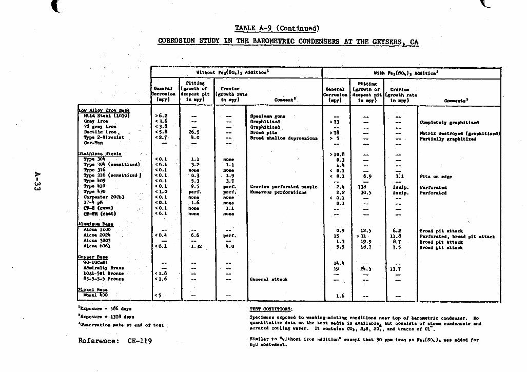
? w w
DV Alloy Iron h a c Hild S t e e l (lalo) Gray iron a c(r.l im mlct i le iron, Typa 2-Ellresist Cor-fen
Lainless S t e e l s W P 304 Type 304 ( sens i t ized)
'Exposure - 586 day.
'bpoaura = 1378 days
TABLE A-9 (Continued)
CORROSION STUDY IN THE BAROMETRIC CONDENSERS AT TIM GEPSERS, CA
Without Ire'(80b)r Addition'
> 6.2 < 3.6 < 3.8
5.8 < 2.7 -- <0.1 C O . 1 <0.1 0.1
c 0.1 0.1
< 1.0 < 0.1 < 0.1 < 0.1 (0.1
-- c 0.5
< 0.1 --
-- -- c 1.8 < 1.6
c 5
'Obscrvation sate at end of t e a t
Reference: CE-119
P i t t i n 8 ; r m h of repeat p i t i n DPY)
~
-- I -
26.5 4.0 -- 1.1 3.2
nOue 0.3 5.3 9.5 perf. none 1.6
none none
-- 6.6 -- 1.32 .
- -- I -- -
C-nt
Bpaol~en gone Orrphitlrud O l r p h l t i z e d Brord p i t a B r d shellw deyresaioas
L-erice perforated sample Numerous perforat iona
Jeneral a t tack
&aments'
h p l e t o l y & r a p h i t i a d
Ehtr lx deatroyed (graphi t ized P a r t i a l l y graphi t i red
P i t s on edee
verrorattd Perforated
Broad p i t a t tack Perforated, broad p i t a t tnck Broad p i t a t tack Brood p i t a t t a c k
S p e c l u n s expoaed t o uashing-alsting condition. near t o p of b a r m e t r i c condenaer. quant i ta t ive d a t a on t h e test media is avai lable* but conalata of a t e m condensate and aurated cooling voter.
Siai lnr t o "u l tho~i t i ron Hddition" except t h a t 30 ppm i ron as Pea(SOb), una added for 1129 abatement.
No
It contains Cot, flr8, 00,. and t rncea of Cl- .
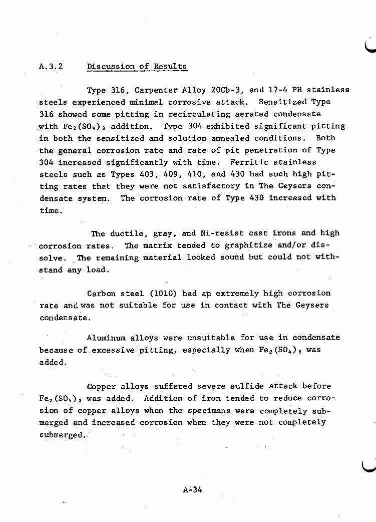
A. 3.2 D i s cus s ion of Resul t s
Type 316, Carpenter Alloy 20Cb-3, and 17-4 PH s t a i n l e s s steels experienced minimal corrosive at tack. 316 showed some p i t t i n g i n r ec i r cu la t ing aerated condensate with Fe2 (SO4) addi t ion. Type 304 exhibi ted s ign i f i can t p i t t i n g i n both the sens i t ized and so lu t ion annealed conditions. Both the general corrosion rate and ra te of p i t penetrat ion of Type 304 increased s ign i f i can t ly with t i m e . steels such as Types 403, 409, 410, and 430 had such high p i t - t i n g rates t h a t they were not s a t i s f ac to ry i n The Geysers con- densate system. The corrosion rate of Type 430 increased with time.
Sensi t ized Type
F e r r i t i c s t a i n l e s s
The duc t i l e , gray, and Ni-resist cast i rons and high
The remaining material looked sound but could not with- corrosion rates. solve. stand any load.
The matrix tended t o graphi t ize and/or d i s -
Carbon steel (1010) had ap extremely high corrosion rate andwas not su i t ab le fo r use i n contact with The Geysers condensate.
Aluminum al loys were unsui table f o r use i n condensate because of excessive p i t t i n g , especial ly when Fez (SO,) w a s added. i
Copper a l loys suffered severe su l f ide a t tack before Fe2(S04)3 w a s added. Addition of i ron tended t o reduce corro- s ion of copper a l loys when the specimens were completely sub- merged and increased corrosion when they were not completely submerged.
A-34
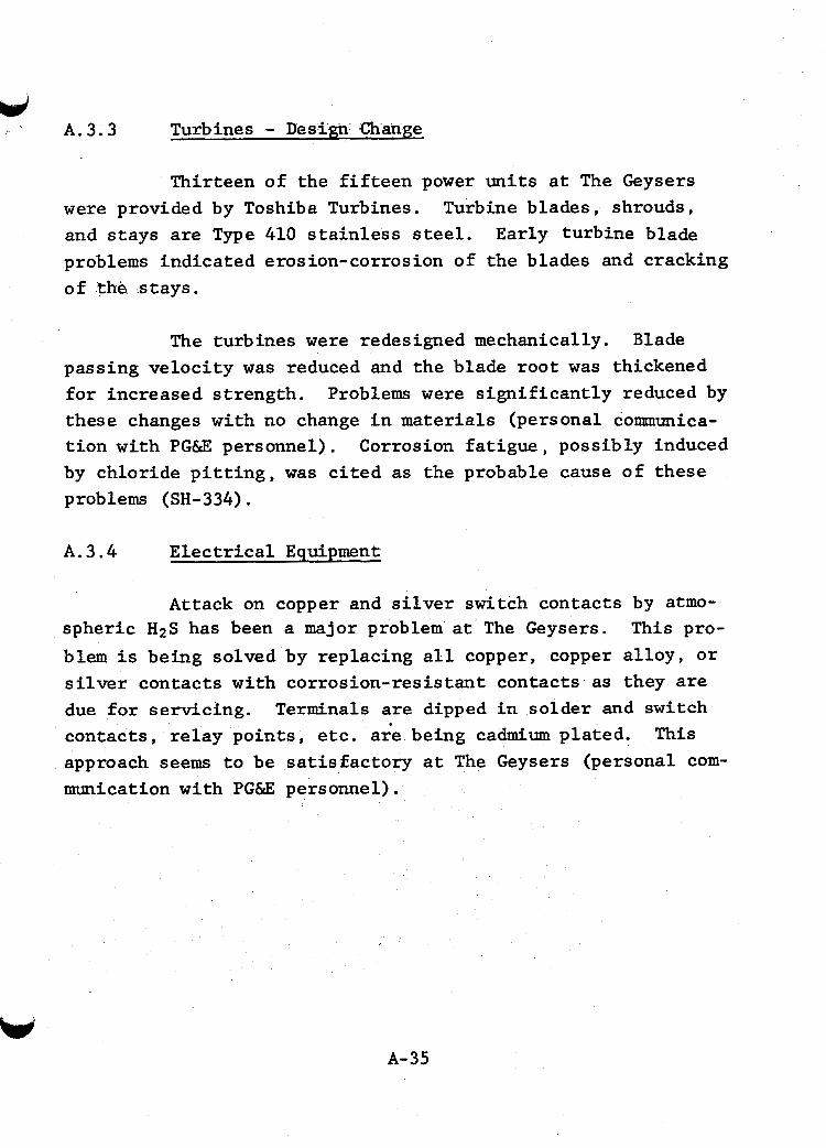
A. 3.3 Turbines - Design Change w
Thirteen of the f i f t e e n power units a t The Geysers w e r e provided by Toshiba Turbines. Turbine blades, shrouds, and s tays are Type 410 s t a i n l e s s s t e e l . Early turbine blade problems indicated erosion-corrosion of the blades and cracking of the .stays.
The turbines were redesigned mechanically. Blade passing ve loc i ty w a s reduced and the blade root w a s thickened f o r increased s t rength. these changes with no change i n materials (personal communica- t i o n with PG&E personnel). by chlor ide p i t t i n g , was c i t e d as the probable cause of these problems (SH-334).
Problems w e r e s ign i f i can t ly reduced by
Corrosion f a t i g u e , possibly induced
A.3.4 E l e c t r i c a l Equipment
Attack on copper and si lver switch contacts by atmo- spheric H2S has been a major problem a t The Geysers, blem i s being solved by replacing a l l copper, copper a l loy , o r si lver contacts with corrosion-resis tant contacts as they are due f o r servicing. Terminals are dipped i n solder and switch contacts , r e l ay poin ts , etc. aie being cadmium plated. approach seems t o be sa t i sgac tory a t The Geysers (personal com- munication with PG&E personnel).
This pro-
This
A-35
APPENDIX B CORROSION IN SEAWATER DESALINATION PLANTS
B - 1
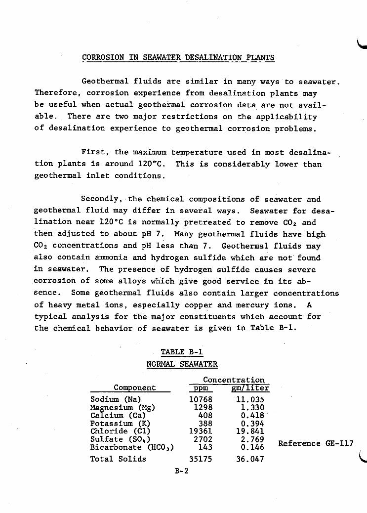
-_ CORROSION IN SEAWATER DESALINATION PLANTS
Geothermal fluids are similar in many ways to seawater. Therefore, corrosion experience from desalination plants may be useful when actual geothermal corrosion data are not avail- able. There are two major restrictions on the applicability of desalination experience to geothermal corrosion problems.
First, the maximum temperature used in most desalina- tion plants is around 120°C. This is considerably lower than geothermal inlet conditions.
Secondly, the chemical compositions of seawater and geothermal fluid may differ in several ways. lination near 120°C is normally pretreated to remove CO2 and then adjusted to about pH 7. C02 concentrations and pH less than 7. Geothermal fluids may also contain ammonia and hydrogen sulfide which are not found in seawater. corrosion of some alloys which give good service in its ab- sence. of heavy metal ions, especially copper and mercury ions. A
Seawater for desa-
Many geothermal fluids have high
The presence of hydrogen sulfide causes severe
Some geothermal fluids also contain larger concentrations
typical analysis for the major constituents which account for the chemical behavior of seawater is given in Table B-1.
TABLE B - 1 - NGRMAL SEAWATER
Concentration Component
Sodium (Na) Magnesium (Mg) Calcium (Ca) Potassium (K) Chloride (Cl) Sulfate (SO,,) Bicarbonate (HC03)
ppm gm/liter 10768 11.035 1298 1.330 408 0.418 388 0.394
19361 19.841 2702 143 2m769 Reference GE-117 0.146
Total Solids 35175 36.047 B-2
B. 1 Corrosion Results
The results of corrosion tests in desalination facili- ties are discussed below for several metals.
B.l.l Aluminum
Geothermal experience indicates that the usefulness of aluminum in contact with geothermal fluids is limited. it did well in corrosion tests at Cerro Prieto, aluminum failed
Though
rapidly in service as oil and hydrogen cooling heat exchangers exposed to aerated cooling waters. poorly in desalination environments. creased by heavy metal ions. lem; aluminum is anodic to most other metals and must be insu- lated from all contact (GE-117).
Aluminum a'lso performs The tendency to pit is in-
Also, galvanic coupling is a prob-
B. 1.2 Copper-Based Alloys
Uniform corrosion data for 12 copper alloys tested at the OSW Materials Test Center are presented in Table B-2. results are for seawater controlled at pH 7.4; corrosion increases rapidly at pH less than 7.0. noted for copper alloys, ment corrosion. per alloys to pit unde is greater than 8 fps. H2S and N H 3 (or "I, ) greatly increase the pitting of copper alloys. corrosion cracking and become major hazards if exposed to "3, "I,+, or Hg. zard under these conditions. zinc must be inhibited with arsenic or antimony to prevent de- alloying (GE-117).
These
Other types of corrosion were also
Destruction of the CuO film will cause all cop- Table B-3 shows the results of impinge-
eposits or where the seawater velocity + Alloys 433 and 687 undergo stress
Alloy 706 is a minor stress corrosion cracking ha- Brasses with more than 15 percent
w B-3
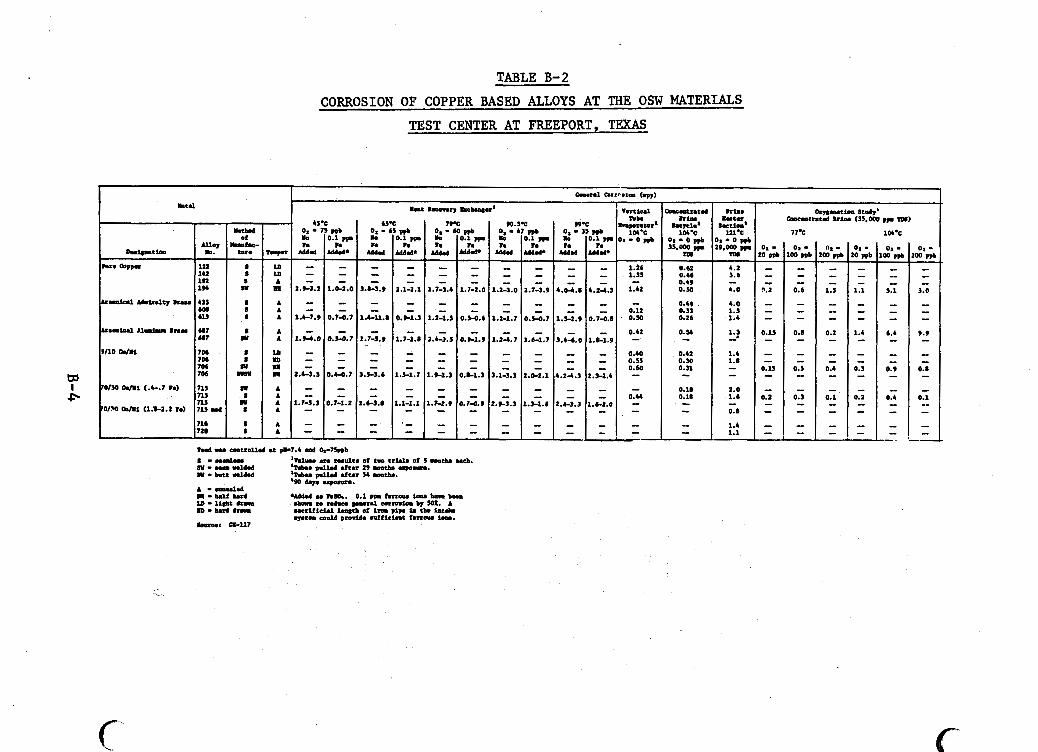
TABLE B-2 CORROSION OF COPPER BASED ALLOYS AT THE OSW MATERIALS
TEST CENTER AT FREEPORT, TEXAS
'I 45.c mcwd 0. 75 ppb
h f u - h h Of Io 0.1 rn
c v * rmpr Mdd M a d 4
s m - - 6 L D - - S A - - su .I 2 . ~ s . 2 1.0-2.0
S A - - S A - - S A 1.4-7.9 0.74.7
a ~ - - Y A 1.94.0 0.5-0.7
S L D - - s m - - R E - -
wI1) I l l 2.4-3.3 0.44.7
R A - - S A - - .I A 1.7-S.3 0.7-1.2 S A - -
S A - - S A - -
77% I 1m.c
30 nb 200 prb LI2-l 0.U 0.49 0.50 I Lo
"0::: I 0.26
4.0 1.3 1.4
1.2 - 1.4 1.8 - - 2.0 1.6
0.8
1.4 1.1
- -
- 0.12 0.50
0.42 - 0.34 - 0.42 0.30 0.31 -
i
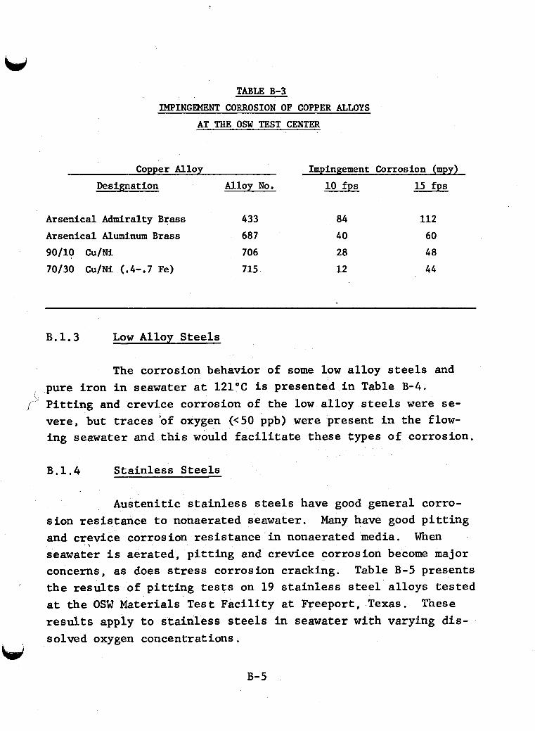
TABLE B-3 IMPINGEMENT CORROSION OF COPPER ALLOYS
AT THE OSW TEST CENTER
Copper Alloy Impingement Corrosion (mpy) Designation Alloy No. 10 fps 15 fps
Arsenical Admiralty Brass Arsenical Aluminum Brass 90/10 Cu/Ni 70/30 Cu/Ni (.4-.7 Fe)
433 687 706 715
84 112 40 60 28 48 12 44
B.1.3 Low Alloy Steels
The corrosion behavior of some low a l loy s t e e l s and pure i ron i n seawater a t 121°C i s presented i n Table B-4.
jflJ P i t t i n g and crevice corrosion of the low a l loy steels w e r e se- vere , but t races 'of oxygen ( ~ 5 0 ppb) were present i n the flow- ing seawater and t h i s would f a c i l i t a t e these types of corrosion.
B.1.4 S ta in less Steels
I
Austeni t ic s t a i n l e s s steels have good general corro- s ion resistance t o nonaerated seawater. Many have good p i t t i n g and crevice corrosion res i s tance i n nonaerated media. When seawater i s aerated, p i t t i n g and crevice corrosion become major concerns, as does stress corrosion cracking. Table B-5 presents t h e results of p i t t i n g tests on 19 s t a i n l e s s steel a l loys t e s t ed a t t he OSW Materials T e s t F a c i l i t y a t Freeport , Texas. These results apply t o s t a i n l e s s steels i n seawater with varying d i s - solved oxygen concentrations.
,
u B-5
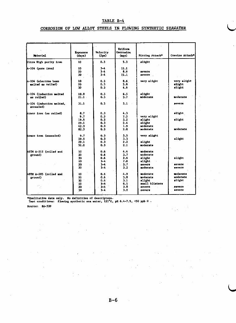
TABLE B-4
CORROSION OF LOW LLOY STEELS IN FLO~ING SYNTHETIC SEAWATER
r kterial I
Ultra High puri ty i ron
A-104 (pure iron)
A-104 (electron beam melted as rol led)
A-104 (induction melted as ro l led)
A-104 (induction melted. annealed)
Armco i ron (as rol led)
Armco iron (annlaled)
ASZM A-212 ( rol led and ground)
ASRI A-285 ( rol led and ground)
Exposure (days)
10
10 20 30
10 20 30
10.8 21.1
31.1
8.7 9.7 19.5 29.1 42.3 82.3
9.7 19.5 29.1 51.0
10 20 30 10 20 30
10 20 30 10 20 30
e l o c i t y ( f p )
0.3
3-4 3-4 3-4
0.3 0.3 0.3
0.3 0.3
0.3
0.3 0.3 0.3 0.3 0.3 0.3
0.3 0.3 0.3 0.3
0.6 0.6 0.6 3-4 3-4 3-4
0.6 0.6 0.6 3-4 3-4 3-4
5.3
11.1 8.9 11.1
8.6 5.0 4.9
6.5 3.7
3.1
4.3 7.3 3.2 2.4 1.9 2.0
5.5 3.3 2.2 2.1
4.4 3.7 2.6 7.0 3.7 3.2
4.9 3.8 3.1 6.1 3.8 3.0
‘ i t t i n g Mtack*
s l i g h t
severe severe
very s l i g h t
s l i g h t w d e r a t e
very s l i g h t a l i g h t s l i g h t -derate moderate
very s l i g h t
s l i g h t moderate
moderate moderate s l i g h t s l i g h t severe moderate
moderate moderate s l i g h t small b l i s t e r s severe severe
*Qualitative data only.
Source: BA-539
lo def in i t ion of descriptors. T e s t conditions: f l w i n g synthet ic sea water, 121’C. pE 6.4-7.9, (50 ppb 0
Crevice Attack‘
very s l i g h t s l i g h t s l i g h t
moderate
severe
s l i g h t
s l i g h t
moderate
a l igh t
s l i g h t
severe severe
moderate moderate s l i g h t
severe severe
B-6
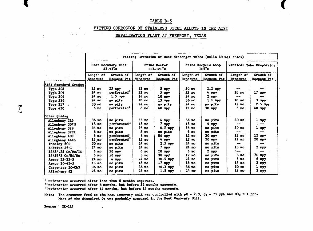
.. .
U S 1 Standard Grades Type 202 Type 304 Type 309 Type 316 Type 317 Type 430
k h e r Grades Allegheny 216 Allegheny 304N Allegheny 329 Allegheny 329X Allegheny 409 Allegheny 444L Incoloy 800 E-Br i t e 26-1 18121.25 CrlMolTi 1811812 CrlNilMn ~ C O 22-13-5 Armco 20-45-5 Carpenter 20433 Allegheny 6X
TABLE B-5
P i t t i n g Corrosion of H e a t Exchanger Tub- (walls 49 mil thick)
H e a t Rec.overy U n i t B r i n e R e s t e r Brine Recycle Loop Vertical Tube Evaporator 43-93OC 113-121°C 105OC
Length of Growth of Length of Growth of Length of Growth of Length of Growth of Exposure Deepest P i t Exposure Deepest P i t Exposure Deepest P i t Exposure Deepest P i t
30 mo 2.2 mpy - - 12 mc 25 mpy l2mo 5 mPY 24 mo perforated' 12 mo 5 mPY 12 mo 4 mPY 24 mo 1.5 mpy 24 mo 1 0 mpy 24 mo 2 mPY 24 mo no p i t s 18 mo 13 mpy 36 mo 1.1 mpy . 18 mo 3 mw
18 mo 17 mpy -- I
30 mo no p f t s 24 mo no p i t s 24 mo no p i t s 12 mo 2.5 mpy 6 mo perforated' 6 mo' 40 mpy 12 mo 30 mpy 6 mo 40 mpy
36 mo no p i t s 36 mo 4 mPY 36 mo no p i t s 30 mo 1 mPY 18 mo perforated2 18 mo 7 mw 18 mo 4 W Y 36 mo no p i t s Mmo 0.5 mpy 36 mo no p i t s 30 mo 1 mPY
6 mo no p i t s 6 mo no p i t s 6 mo no p i t s -- 6 mo perforated' 6 mo 80 mpy 12 mo 30 mpy 12 mo 12 mpy
l2 mo 20 mpy 12 mo 20 mpy 12 w, perforated2 12 mo 4 mPY
24 mo no p i t s 24 mo 7 mPY 24 mo no p i t s 18 mo 2 mw
24 mo 4 mpy 24 mo a . 5 mp9 24 mo no p i t s 6 mo 6 mPY 18 mo no p i t s 18 mo 17 mpy 18 mo no p i t s 18 mo 3 mPY 36 mo no p i t s 36 mo a . 3 mpy 36 mo no p i t s 30 ma 1 mPY 24 mo no p i t s 24 mo 1.5 mpy 24 mo no p i t s 18 mo 2 mPY
-
-- -- 30 mo no p i t s 24 ma 2.5 mpy 24 mo no p i t s
-- 6 mo 50 mpy 6 mo 10 mpy 6 m 2 mPY 12 mo no p i t s 6 mo 70 mpy 6 mo 50 mpy 6 mo 30 mpy
P I T T I N G CORROSION OF STAINLESS STEEL ALLOYS I N THE AIS1 DESALINATION PLANT AT FREEPORT, TEXAS
APPENDIX C PRELIMINARY COMPARISON OF GEOTHERMAL
FOSSIL FUEL GENERATING PLANT AVAILABILITY
c-1
PRELIMINARY COMPARISON OF GEOTHERMAL _I FOSSIL FUEL GENERATING PLANT AVAILABILITY
Power p lan t downtime o r outage may r e s u l t from-either scheduled preventive maintenance o r f a i l u r e of a c r i t i c a l com- ponent. Estimating outages fo r a geothermal power p lan t i s highly uncertain because the number of operating geothermal f a c i l i t i e s i s s m a l l and there i s no s ign i f i can t s t a t i s t i c a l bas i s f o r making such project ions. An outage report ing system similar to those fo r f o s s i l and nuclear fue l power p lan ts has not been establ ished spec i f i ca l ly f o r geothermal p lan ts . Geo- thermal power plants report t h e i r problems and solut ions through the open l i t e r a t u r e , but are not s p e c i f i c on a unit-by-unit bas i s . Although general trends a r e becoming ava i lab le , exact data from the geothermal industry a r e not avai lable . U n t i l a l a rge r data base is accumulated f o r geothermal power p l an t s , some l imited comparisons can be made with f o s s i l f u e l p lan ts .
Correlation of ex is t ing geothermal data with statis- t ical experience from f o s s i l f u e l p lan ts should help t o determine operations and problems of fu tu re geothermal power p lan ts .
The most frequent outage i n a f o s s i l f u e l power p lan t is due t o boi le r - re la ted problems. Foss i l f u e l b o i l e r s requi re cleaning and inspection and are the leading cause of major power p lan t f a i l u r e s . However, t h i s type of outage does not apply t o geothermal power p lan ts s ince they do not require bo i l e r s .
Turbine-related problems a r e the second most frequent cause of outages i n a f o s s i l fue l p lan t bu t are the major cause of outages i n geothermal p lan ts . Turbine outage i n f o s s i l f u e l p lan ts is generally f o r inspection o r control system mainte- nance. The major causes of turbine outages i n geothermal p lan ts are blade corrosion, erosion, o r f a i l u r e . Geothermal power p lan ts t h a t use a binary cycle w i l l t r ans fe r many of these
c-2
corrosion problems to heat exchangers; the turbines in these systems will more closely parallel those in fossil power plants.
Condenser-related problems are the third most frequent cause of downtime at a fossil power plant. most prevalent reason for outage, but it is of a short duration of about 6 to 8 hours. Condenser problems can be expected to be higher in geothermal power plants because of the chemical composition of geothermal fluids versus fossil fuel steam.
Cleaning is the
Exciter generator maintenance is the fourth major reason for outages at fossil power plants. Exciter generator maintenance can be expected to increase in a geothermal power plant, particularly when the geothermal fluid contains gaseous sulfur species.
The quality of steam in a geothermal power plant is the key to the amount of downtime incurred by that plant. Based upon experience at The Geysers and Cerro Prieto,.less maigp tenance is required on major equipment items as the geothermal fluid becomes cleaner. Equipment such as turbines, generators, condensers, pipes, and heat exchangers that are exposed to geo- thermal fluid should experience more downtime than comparable systems exposed to clean steam in fossil power plants, but down- time will not be lost to boiler problems, More direct correla- tion between fossil and geothermal power plants is not possible because the predominance of outages is due to boiler problems in fossil plants and because outage data specific for geothermal plants are limited.
The cost of maintenance versus capital costs for equip- ment is a driving force toward more frequent maintenance outages
e-3
c, to detect incipient problems before they become major problems. Better materials may be necessary in many geothermal plant appli- cations; best available materials should be considered for cri- tical applications where maintenance and replacement costs could become prohibitive.
c-4
Appendix D
GEOTHERMAL ELASTOMERIC MATERIALS
D-1
GEOTHERMAL ELASTOMERIC MATERIALS
The Department of Energy i s conducting research t o develop elastomers f o r geothermal use. Five research pro- grams are involved i n various phases of the development and t e s t i n g of elastomers f o r use i n geothermal w e l l s . t o seek new materials and tests which w i l l serve i n geothermal appl icat ions. b i t c u t t e r cone seals. t o appl ied development and include synthesis of new polymers, invest igat ion of new but avai lable (a t high cost) elastomers, modification of commonly known materials and development and evaluation of test methods.
The goal i s
O f pa r t i cu la r i n t e r e s t are packer seals and d r i l l The approaches range from bas ic research
Results of these ongoing research programs are described below. Each program, conducted by an individual contractor , has d i f f e ren t goals and tes t methods ; therefore , r e s u l t s are grouped according t o research program.
D. 1 Elastomer 0-Ring Seal Program
The object of t h i s study w a s t o tes t commercial e las to- m e r i c materials f o r po ten t ia l appl icat ion as O-ring s e a l s i n geothermal environments. configurations o r #2-329 types.
The O-rings w e r e e i t h e r reed oval The c r i t i c a l propert ies desired
i n the elastomers w e r e :
1 ) low compression s t rength of less than 20%,
2 ) good abrasion res i s tance and high tear s t rength ,
3) resis tance t o a t tack from petroleum-based
D-2
lubr icants , common mud addi t ives , H2S, and moderate s h i f t s i n pH, and
4) re tent ion of the above propert ies a t elevated temperatures.
D. 1.1 T e s t Program
f o l l d r i l
The tes t program invest igated the influence of the .owing var iables on the performance of elastomers i n geothermal l i ng operations :
1) temperature of geothermal formation and from f r i c t i o n ,
2 ) ro t a t iona l e c c e n t r i c i t i e s of d r i l l c u t t e r cones ("wobbling" on the lug) ,
3) abrasive p a r t i c l e s , and
4) chemical composition of the geothermal br ine, espec ia l ly H 2 S which causes b r i t t l e n e s s i n elastomers by creat ing unwanted cross- l inks.
D . 1 . 2 Materials Tested and Results
1) Buna-N (Parker JlN4187) performed well between 10O"C-20O0C w i t h 'no abrasives present . The temperature l i m i t
was approximately 225°C. Preheating of the seal t o 50°C before
use increased l i fespan , but preheating t o 240°C and 260°C, then cooling t o 175°C p r i o r t o d r i l l i n g resu l ted i n extensive seal damage and poor performance. Test t i m e : 4 hours simulated d r i 1 l ing .
1)-3 '
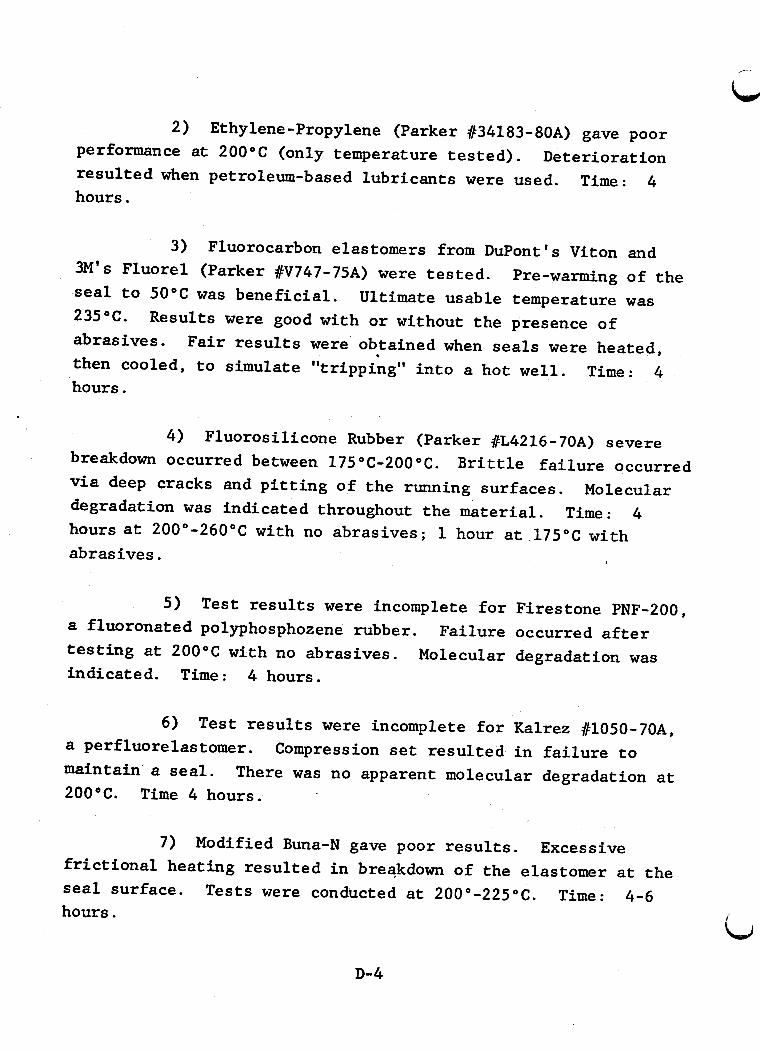
2) Ethylene-Propylene (Parker #34183-80A) gave poor performance at 200°C (only temperature t e s t ed ) . Deterioration r e su l t ed when petroleum-based lubricants were used. Time: 4 hours.
3) Fluorocarbon elastomers from DuPont's Viton and
Ultimate usable temperature was
3M's Fluorel (Parker #V747-75A) were t e s t ed . seal t o 50°C w a s benef ic ia l . 235°C. abrasives. then cooled, t o simulate "tripping" i n t o a hot well .
Pre-warming of the
Results were good with o r without the presence of Fa i r r e s u l t s were obtained when sea l s were heated,
4 Time: hours.
4 ) Fluorosilicone Rubber (Parker #L4216-70A) severe breakdown occurred between 175°C-2000C. Bri t t le f a i l u r e occurred via deep cracks and p i t t i n g of t he running surfaces. Molecular degradation was indicated throughout the mater ia l . Time : 4 h o u r s a t 200"-260°C with no abrasives; 1 hour a t 175°C with abrasives.
5 ) Test r e s u l t s were incomplete f o r Firestone PNF-200, a fluoronated polyphosphozene rubber. t e s t i n g at 200°C with no abrasives. indicated. Time: 4 hours.
Fai lure occurred a f t e r Molecular degradation was
6) Test r e s u l t s were incomplete f o r Kalrez #1050-70A, Compression s e t r e su l t ed i n f a i l u r e t o
There was no apparent molecular degradation a t a perfluorelastomer. maintain a seal. 200OC. Time 4 hours.
7) Modified Buna-N gave poor r e s u l t s . Excessive f r i c t i o n a l heat ing resu l ted i n breakdown of the elastomer a t t he s e a l surface. Tests were conducted a t 200°-225"C. Time: 4-6 hours.
D-4
T e s t r e s u l t s are summarized i n Table D-1.
D. 2 Downhole Packer Seal Program
The object ive w a s the development of elastomers f o r downhole geothermal seals. ing packer seals.
The appl icat ions are f o r use as cas-
D . 2 . 1 Test Program
Simulation (SIM) Tests w e r e designed t o provide a good simulation of the casing packer seal operat ional environment i n the laboratory. stresses simultaneously, i . e . , f l u i d pressure, d f f f e r e n t i a l pressure, temperature, mechanical forces , and br ine chemistry, t o a f u l l sca le packer seal. mulated t o contain: H2S-300 ppm; NaC1-25,000 ppm; CO2-1,OOO ppm; XZO-balance. Elastomers were t e s t ed i n t h i s synthet ic goethermal f l u i d a t 260°C and up t o 5000 psig. o r u n t i l seal f a i l u r e .
The SIM apparatus appl ies a l l environmental
The synthet ic geothermal f l u i d w a s for-
T e s t duration w a s 24 hours
D.2.2 Materials Tested and Results
Five companies supplied the following types of e las to- mers : Viton , and Epochlorohydrin. each were tes ted .
Buna-N (Ni t r i l e ) , Ethylene Propylene Terpolymer (EPDM) , Several d i f fe ren t formulations of
, The r e s u l t s are summarized i n Table D-2.
D. 3 Casing Packer Development Program
The object ive of t he program was t o develop a material
The casing packer should be thermally as a casing packer f o r use a t 260°C, 1500 ps i a , f o r 24 hours i n a geothermal environment.
D- 5
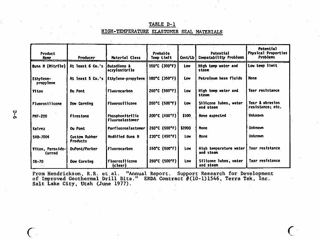
Product Name
Buna N (Wi t r l le) L
Lthylene-
V i ton
propylene
Fluorosl l icone
PNF-200
Ka l rez
5AD-7004
V I ton, Peroxlde- Curred
TR-70
TABLE D-1 HIGH-TEMPERATURE ELASTOMER SEAL MATERIALS
Producer
A t least 6 Co.'s
A t least 5 Co.'s
Du Pont
Don Coming
F1 res tone
Du Pont
Custom Rubber Products
DuPont/Parker
Don Corning
Haterlal Class
Butadlene 6 acrylonl t r l l e
E t h y l ene-propy 1 ene
Fluorocarbon
Fluorosl l icone
Phosphonl trll IC Fluoroelastomer
Perfluoroelastomer
Hodlfled Buna N
F1 uoroca rbon
Fluorosl l Icone (clear)
Probable Temp L iml t
150°C (300°F)
180°C ( 350°F)
260°C (500°F)
260°C (500'F)
200°C (400°F)
260°C (500°F)
230°C (450°F)
260°C ( 500°F)
260'C (500°F)
- Cos t/Lb
LOW
Lon
LOW
LOW
$100
$2000
Lon
LOW
LOW
-
-
Potentlal Conpatability Problems.
~
High temp water and steam
Petroleum base f l u lds
High temp water and steam
S i 1 i cone lubes water and steam
14 one expected
w O n e
None
High temperature water and steam
S i 1 1 cone 1 ubes , water and steam
~~ ~~
Potcn t I a 1 'hys 1 ca 1 Propert 1 es
Problems
LOW temp l l m i t
Yone
rear resls tance
Tear 8 abrasion resistance; etc.
Unknown
Unknown
Unknown
Tear reslstance
Tear reslstance
From Hendrickson, R . R . et al. "Annual Report. Support Research for Development of Improved Geothermal Drill Bits." ERDA Contract #(lo-1)1546, Terra Tek, Inc. S a l t Lake City, Utah (June 1977).
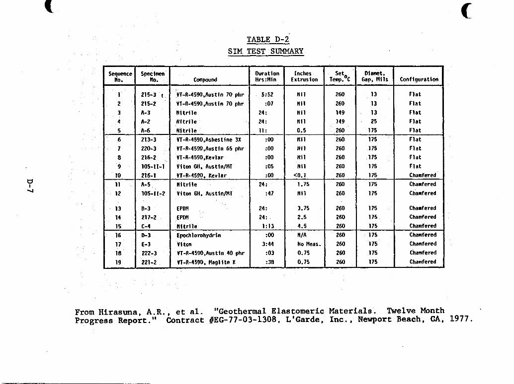
c
Sequence flo .
TABLE D-2 SIM TEST SUMMARY
Speclmen Duration Inches Set, Diamet. NO. compound 1irs:Min Extrusion Temp. C Gap, M i l s Configuration
VT-A-4590,Aus t in 70 pkr
VT-R-45!lO ,Aus t i n 70 phr N i t r i l e N f t r l l e N i t r i l e Vi-R-4590,Asbestine 3X VT-R-4590,Austin 65 phr VT-R-4590,Kevlar Viton GH. AustinIMT
215-3 215-2
220- 3 216-2 105-11-1
5:52 Ni 1 260 :07 N i 1 260
24 : N i l 149 24 : N i l 149 11 : 0.5 260 :oo Ni 1 260 :oo Ni 1 260 :oo N i 1 260 :05 N i 1 260
10 11 12
13 13 13 25
175
216-1 VT-R-4590 , Kevl a r :oo CO. 1 260 175 Chamfered
A- 5 N i t r i l e 24 : 1.75 260 175 Chamfered
105-11-2 Viton GH, Austin/MT : 47 N i l 260 175 Chamfered
175 175
,175 175
F l a t F l a t F l a t F l a t F l a t F l a t F l a t F l a t F l a t
13 14 15 16 17 18 19
N i t r i l e 0-3 Epochlorohydrin
V i ton 222-3 VT-R-4590,Austin 40 phr
24 : 3.75 260 24 : 2.5 260
1:13 4.5 260 I :oo N I A 260
3:44 No fleas. 260
1 :38 0.75 260 I :03 0.75 260
1
C hamf ered 175 Chamfered
Chamfered 175 Chamfered 175 I Chamfered
175 175 I Chamfered 175 Chamfered I
c
From Hirasuna, A.R., et al. "Geothermal Elastomeric Materials. Twelve Month Progress Report." Contract #EG-77-03-1308, L'Garde, Inc. , Newport Beach, CIA, 1977.
s t ab le i n a geothermal environment with 400 p s i t e n s i l e s t rength and a t least 50% elongation.
D. 3.1 T e s t M e tho ds
S t ress r e l a t ion measurements, sol-gel determinations swollen s t r e s s - s t r a in measurements, weight-loss tests, and t e n s i l e tests w e r e conducted after exposure t o three solut ions a t e levated temperatures. The th ree solut ions w e r e s a l ine carbon dioxide solut ion (solut ion f l ; 2.5% N a C l , 1000 ppm C O P ) , s a l i n e hydrogen su l f ide (solut ion #2; 2.5% NaC1, 300 ppm HPS), and deionized water (solut ion f3) .
D.3.2 Materials Tested and Results
The materials t e s t e d w e r e :
1 ) Viton 10, 10K, 10G (du Pont)
2 ) Kalrez 3065, 3050 (du Pont)
3) AFLAS 150H (Asahi Glass, Yokohama, Japan)
Table D-3 summarizes the mechanical propert ies of aged elastomers, and Figure D - 1 shows the e f f e c t of aging on the t e n s i l e s t rength of the elastomers. Results of the elastomer classes are given below.
1 ) Viton - Viton-1OG underwent less oxidat ive degen- e ra t ion during s t ress-relaxat ion tests than the other Viton for- mulations. Substant ia l cross-l inking was observed i n a l l formu- . la t ions. Cross-link dens i t ies did not decrease not iceably i n any formulation when sol-gel measurements were made. Weight-loss
D-8
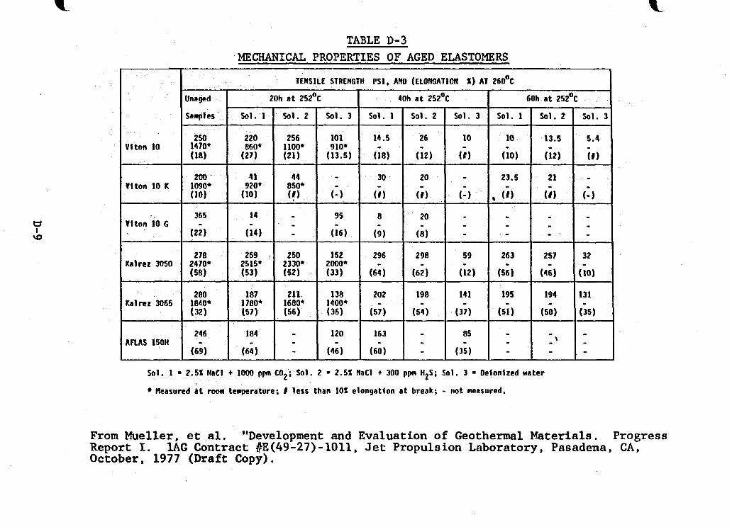
Viton 10
Viton 10 K
vi ton 'io G
Kalrez 3050
Kalrer 3065
AnAS 150H
TABLE D-3 MECHANICAL PROPERTIES OF AGED ELASTOMERS
TENSILE STRENGTH PSI, Aft0 (ELONGATION X) AT 260°C
Unaged 20h a t 252% I 40h at 252% I 60h a t 252%
Sol. 1 - 2.5% NaCl t loo0 ppm COP; Sol. 2 = 2.5% NaCl t 300 ppm HZS; Sol. 3 = Deionized water
Measured at room temperature; I less than 10% elongation a t break; - not measured.
From Mueller, et al. "Development and Evaluation of Geothermal Materials. Progress Report I. l A G Contract #E(49-27)-1011, Jet Propulsion Laboratory, Pasadena, CAD October, 1977 (Draft Copy).
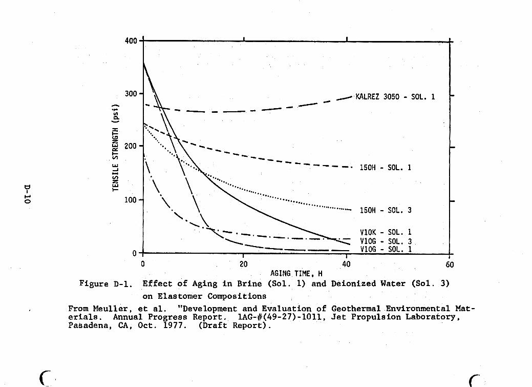
400
300 n
v) * n Y
I I- z 2 200 t;; W
v) z W I-
100
0
I I I
Figure D-1. Effect o t Aglng In arrne [ D O L . 11 ~ I I U S J G A W L L ~ - ~ ,---. -, on Elastomer Compositions _ _
From Meuller , et al. erials. Annual Progress Report. 1AG-#(49-27) -1011, Jet Propulsion Laboratory, Pabadena, CA, Oct. 1977. (Draft Report).
"Development and Evaluation of Geothermal Environmental Mat-
c 6
measurements a f t e r aging i n br ine solut ion #l f o r 60 hours a t 250°C w e r e :
Viton 10 - 9% loss Viton 10K - 13% loss Viton 10G - 17% los s
Mechanical propert ies ( tensi le /e longat ion s t rength) w e r e low f o r the Vitons after 40 hours i n each of the three test solut ions.
2) Kalrez - In stress relaxat ion s tudies , Kalrez 3050 and 3065 behaved s imi la r ly t o Viton 10G, except t h a t both w e r e more thermally s t ab le than the Vitons. Cross-link densi- t i es did not appreciably decrease when sol-gel measurements were made. Weight-loss measurements i n solut ion 81 f o r 60 hours at 250°C w e r e :
Kalrez 3050 - 2% loss Kalrez 3065 - 8% loss
A f t e r 40 hours i n solut ion #3, Kalrez 3065 re ta ined 50% of i n i t i a l t e n s i l e s t rength and 100% of i n i t i a l elongation. o ther solut ions Kalrez 3050 and 3065 were s t a b l e f o r 60 hours.
AFLAS-15OH - This polymer w a s avai lable only i n s m a l l quan t i t i e s and w a s not t e s t e d extensively. No stress relaxat ion o r sol-gel measurements were performed on AFLAS-15OH. Weight l o s s i n br ine so lu t ion #l w a s 1%. Tensi le s t a b i l i t y i n a l l t h ree br ine solut ions was g rea te r than t h a t of the Vitons but less than t h a t of Kalrez 3050 o r 3065.
In
3)
A f t e r one year ' s work, no candidate elastomer appeared t o s a t i s f y the object ive requirements of t he pro jec t . Kalrez
D-11
3050 appeared t o be the bes t , but it i s too expensive t o be used i n casing packers. AF'LAS w a s b e t t e r than Viton. Since no com- mercial ly avai lable products appear t o be sa t i s f ac to ry , new elastomers f o r high temperature geothermal appl icat ions are being synthesized.
D .4 Elastomer Synthesis and Development Program
The object ive of t h i s program was the invest igat ion of materials and techniques f o r production of high temperature- and hydrolyt ical ly r e s i s t a n t rubber. vest igated: 1 ) carborane-siloxane (Union Carbide), 2) "FASIL", a f luorinated elastomer being synthesized by Hughes Ai rc ra f t , and 3) an ethynyl subs t i tu ted perfluoroalkylene e the r elastomer being synthesized by Hughes. cable terminations and cable insulat ions i n geothermal w e l l logging instrumentation. Materials t e s t e d thus f a r have been i n the developmental s tages and have not been formed i n t o anything but 1/4" x 1/8" "buttons".
Three materials w e r e in-
The materials were t o be used as seals,
D.4.1 Results
Various polymers of carborane-siloxane w e r e formulated (Table D-4) and t e s t e d f o r compression se t , durometer hardness (an indicat ion of cross- l inking) , t e n s i l e s t rength/elongat ion, and hydrolyt ic s t a b i l i t y under pressure. Results of compression set tests f o r the most promising formulations are shown i n Table D-5, along with hardness tests r e s u l t s . Hydrolytic s t a b i - l i t y tes t conditions were 24 hours a t 275°C and 800 p s i . p l e t e d i s in tegra t ion of the polymer w a s noted, regardless of formulation used o r type of w a t e r ( tap o r d i s t i l l e d ) . Further work on t h i s compound has been suspended u n t i l information regarding i t s hydrolyt ic i n s t a b i l i t y can be found.
Com-
D-12
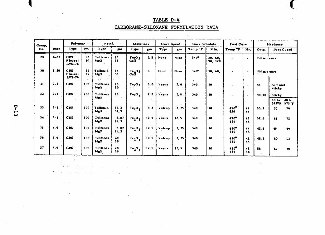
Schedule
Min.
30, 60, 90, I 20
30, 60,
30
30
30
30
30
3 0
30
nt.t c T e r n p o l
e TABLE D-4
CARBORANE-SILOXANE FORMULATION DATA
r - w - -
50 50
75 25
100
100
io0
100
I O 0
LOO
lo0
-
Stabil izer tent Cure e
H r. - - -
48 48
48 48
40 48
48 48
48 48 -
Cure rwm Type
CIS F hto re1 LVS-76
C I S Fluorel LVS-76
C RS
CIS
c OS
COS
CN: .
CRS
c DS
-
nti
TYPC
T u l l a w x M P
fa l lamix M 6)
TU~~~IMDX M d )
M f P
lu l lanux M e
Tullanox M g O
Tullanox M f l
Tullanox M i 9
M IrO
Tullanox
Tullanox
Ha rdneoe
Orig. I I%at Cured &imp.
Nu.
29
-
30
3 1
32
33
34
35
36
37
Data - - 6-27
6-28
7-7
7- 7
8- I
n- I
0-9
8-9
8-9
-
-- Temp up ani -
15 35
15 35
I S 20
15
t3 .3 31.9
5.17
5.87
14.3
14.3
20 50
20 50 -
g m
Nnne
- -
None
2.0
2. 5
3. 13
12. 5
3. 75
3. 75
12.5
T v'P.
None
None
V a lytx
Va mix
\ ulcup
Vurox
Vulcup
Vulcup
Varux
-
34ou
34ou
340
340
340
3 4 0
340
340
340
&ioo 5 25
4 5 B 525
4soO 5 25
450" S25
450° 525
I did nut cure
did not cure
45
4 0 - S O
53. 3
52. 6
42. 5
48. 2
56
-
Silt and etlcky
Stickv
48 hr 40 hr 525°F 575OF
70 79
61 72
45 49
60 63
67 70
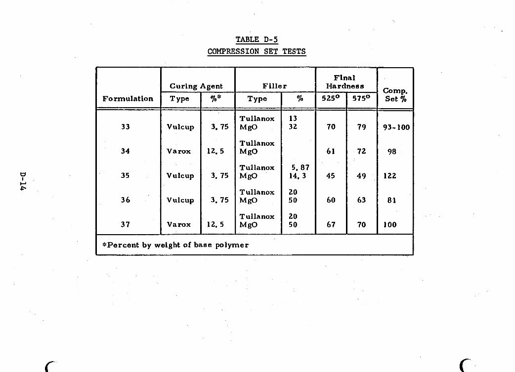
c
Formulation
33
34
35
36
37
Type
Vulcup
Varox
Vulcup
Vulcup
Varox
TABLE D-5 COMPRESSION SET TESTS
Curing Agent -
%*
3. 75
12.5
3. 75
3, 75
12. 5
Fi l ler
Tullanox MgO
MgO
MgO
MgO
MgO
T ullanox
Tullanox
T ullanox
T ulla nox
%
13 32
5, 07 14, 3
20 50
20 50
Flnal Hardness
5 25O
70
61
45
60
67
575O
79
72
49
63
70
*Percent by weight of base polymer
Compo Set 70
93-100
98
122
81
100
c
Hughes synthesized a f luorinated elastomer ("FASIL") , but no materials t e s t i n g has been done on t h i s mater ia l ; work has stopped i n t h i s area because of the hydrolyt ic i n s t a b i l i t y of siloxane-type polymers.
Synthesis of perfluoroalkylene e the r elastomers i s con- t inuing, but no sa t i s f ac to ry material has yet been developed
D. 5 Program t o Develop and Evaluate Elastomers
The object ives of the program were 1 ) t o develop and evaluate coating processes f o r elastomers t o be used i n deep wel ls , and 2) t o evaluate commercial elastomers f o r use i n a geothermal borehole logging too l . f o r e las tomeric mater ia l i n general , but Kalrez O-rings received s p e c i f i c a t ten t ion .
Application poten t ia l s w e r e
Kalrez, a perfluorbnated elastomer from DuPont has good po ten t i a l f o r deep w e l l appl icat ion because of i t s high thermal s t a b i l i t y and chemical res is tance. I ts usefulness (especial ly i n packer manufacture) is l imited by i t s high cost : $2000/lb.
D.5.1 T e s t Program
0
The following elastomers were coated with a 400 A-thick coating of cross-l inked poly ( te t raf luoroethylene) using an RF Glow Discharge apparatus : 1) Kalrez (DuPont)l 2) Fairprene BS-5565 (Buna-N, DuPont); 3) Buna-N (Parker) ; 4) Viton V-747-75 (Parker). Samples were aged i n a sour gas (composition not pro- vided) environment f o r one month a t 200°C.
D-15
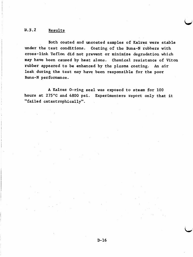
u.5.2 Results
Both coated and uncoated samples of Kalrez were s t ab le under the tes t conditions. cross- l ink Teflon did not prevent o r minimize degradation which may have been caused by heat alone. rubber appeared t o be enhanced by the plasma coating. leak during the tes t may have been responsible f o r t h e poor Buna-N performance.
Coating of t he Buna-N rubbers with
Chemical res i s tance of Viton An a i r
A Kalrez O-ring seal was exposed t o steam f o r 100 hours at 275°C and 4800 p s i . " fa i led catastrophical ly" .
Experimenters report only t h a t it
,
D-16
!
APPENDIX E COMPARATIVE ALLOY COSTS
E-1
!
I
C
COMPARATIVE ALLOY COSTS
Table E-1 lists the comparative costs of ten common truction alloys. The costs of the alloys are normalized and
compared to AIS1 Type 304L stainless steel, a widely-used alloy. All values in Table E-1 are comparative values ratioed to 1.00 for Type 304L and do not represent actual dollar values. The comparative costs in Table E-1 were assembled after examining available information and talking to alloy suppliers.
The alloy cost comparisons in Table E-1 are based on the same dimensions of bulk metal sheet for each alloy. does not take into account the factors involved in fabricating an alloy for a particular application. ments may require such a thicker plate of lower cost, less re- sistant alioy that using a normally more expensive but resistant alloy will actually result in lower initial costs because a much thinner plate can be substituted.
This
Some corrosive environ-
E-2
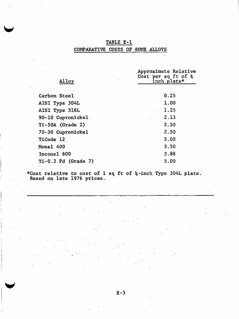
Alloy
TABLE E-1 COMPARATIVE COSTS OF-SOME ALLOYS
Carbon Steel AISI Type 304L AISI Type 316L 90-10 Cupronickel Ti-50A (Grade 2) 70-30 Cupronickel TiCode 12 Monel 400 Inconel 600 Ti-0.2 Pd (Grade 7)
Approximate Relative Cost per sq ft of %
inch plate*
0.25 1.00 1.25 2.13 2.50 2.50 3.00 3.50 3.88 5.00
*Cost relative to cost of 1 sq ft of %-inch Type 304L plate. Based on late 1976 prices.
E-3
APPENDIX F -
PRELIMINARY LIST OF AVAILABLE GEOTHERMAL POWER EQUIPMENT
PRELIMINARY LIST OF AVAILABLE GEOTHERMAL POWER EOUIPMENT
Table F-1 i s a preliminary l i s t of suppl iers of geo- thermal equipment. matively t o an i n i t i a l survey directed toward ident i fying firms t h a t manufacture equipment spec i f ica l ly fo r geothermal applica- t ions. This l i s t i s not intended t o be a l l - inc lus ive and i s f o r
The l i s t includes firms t h a t responded aff i r -
those groups who may need to know potent ia l manufacturers but who do not have access t o such vendors through normal channels. l i s t is only a s t a r t i n g point i n ident i fying the equipment t h a t may be needed t o u t i l i z e a geothermal resource.
The
F-2
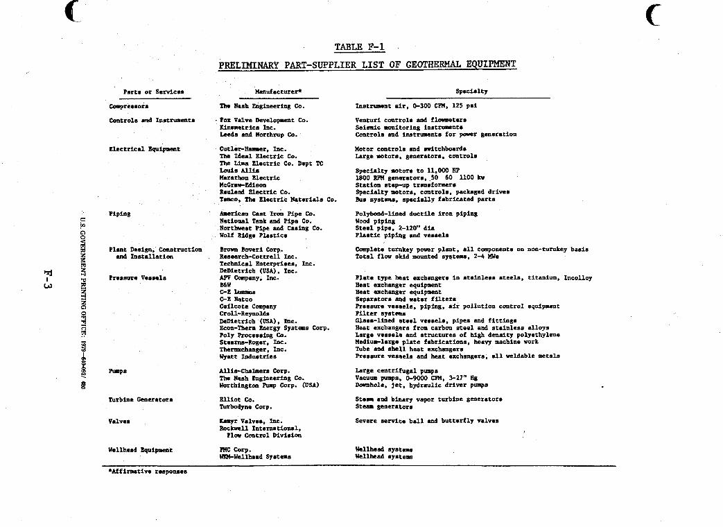
Par ts or Services
compressors
Controls and Instruments
Elec t r ica l Equipment
Plant Derign. Construction sad I n s t a l l a t i o n
Pressure Vessels
Turbine Generators
Valves
Wellhead Equipment
TABLE F-1
PRELIMINARY PART-SUPPLIER LIST OF GEOTHERMAL EQUIPMENT
Manufacturer* Specialty
The Nash Engineering Co. Instrument air, 0-300 CFM. 125 p s i
Fox Valve Lkvelopm,cnt Co. M n w e t r i c s Inc. Leeda and Northrup Co.
Venturi controls and fl-ters Seismic monitoring instruments Controls and instruments f o r power generation
C u t l e r H a s c r , Inc. The Idea l Electr ic Co. The Lima Electr ic Co. Dept TC Louis Allis Marathon Electr ic 1800 RPPI generators, 50 60 1100 Irv WCGrtr-Edison Sta t ion step-up transformers Reulaad Electric Co. TUDCO, The Elec t r ic Materiala Co.
h e r i c a n b a t I& Pipe CO. National Tank and Pipe Co. Northwest Pipe and Casing Co. Wolf Ridge P las t ics
Motor controls and .witchboards Large motors, generators, controls
Specialty motors t o 11.000 Bp
Specialty ro tors . controls , packaged dr ives Bus systems. spec ia l ly fabr icated p a r t s
Polybond-lined d u c t i l e i ron piping
S t e e l pipe, 2-120" d i a P l a s t i c piping and vessels
wood piping
Brown h e r i Corp. Research-Cottrell Inc. Technical Enterprises, Inc. DeDietrich (USA). Inc.
B h W C-E Iummw D E Natco Cei lcote Company Croll-Reynolds DeDietrich (USA), hrc. Ecrm-Then Energy Sy6te0e Corp. Poly Processing Co. Steam-Roger, Inc. Themchanger , Inc. Wyatt Industr ies
Allis-Chahers Corp. The Rash Engineering Co. Uorthingtoa Pump Corp. (USA)
E l l i o t co. Turbodyne Corp.
Kamyr Valves. Inc. R4c lml l Internat ional ,
Flow Control Division
R4C Corp. WIM-Wellhead Systems
m Company, Inc.
Complete turnby power plant , a l l components on non-turnkey basis Total flow skid mounted sntems. 2-4 me
Ela te type h a t exchangers in s t a i n l e s s s t e e l s , titanium. Incolloy Heat exchangtr equipment Heat srchangtr equipment Separators and water f i l t e r s Pressure veseels. piping, air pol lut ion control equipment F i l t e r systems Glass-lined steel vessels. pipes and f i t t i n g s X e a t exchangers from carbon s t e e l and s t a i n l e s s a l loys Large vesse l r and s t ruc tures of high densi ty polyethylene Mediuwlarge p l a t e fabr icat ions. heavy machine work Tube and s h e l l heat exchangers Pressure vessels and heat exchangers. a l l weldable metals
Large cent r i fuga l punpa Vacuum pumps, 0-9000 CFM, 3-27" Bg Downhole, jet, hydraulic dr iver pump6
S t e m a d binary vapor turbine generators Steam generators
Severe service b a l l and but te r f ly valves
Wellhead systems Wellhead systems
c
*Affirmative responaes