Embed Size (px)
Citation preview

Norman Ernst November 2011Yanick CrutzenNicolas Vanden Branden
Materials SelectionMaterials for mechanical watches
Prof. Jacqueline Lecomte-Beckers
Academic Year 2011-2012University of LiègeFaculty of Applied SciencesDepartement of Aerospace and Mechanics

Contents
1 Introduction 2
2 About mechanical watches 32.1 What are mechanical watches made of? . . . . . . . . . . . . . . . . . . . . . . . . . . . . 3
2.1.1 Internal part . . . . . . . . . . . . . . . . . . . . . . . . . . . . . . . . . . . . . . . 32.1.2 External part . . . . . . . . . . . . . . . . . . . . . . . . . . . . . . . . . . . . . . . 3
2.2 How do mechanical watches work? . . . . . . . . . . . . . . . . . . . . . . . . . . . . . . . 42.3 Review of materials in nowadays watches . . . . . . . . . . . . . . . . . . . . . . . . . . . 42.4 Innovative materials . . . . . . . . . . . . . . . . . . . . . . . . . . . . . . . . . . . . . . . 5
3 Materials selection 73.1 Introduction . . . . . . . . . . . . . . . . . . . . . . . . . . . . . . . . . . . . . . . . . . . . 73.2 Springs . . . . . . . . . . . . . . . . . . . . . . . . . . . . . . . . . . . . . . . . . . . . . . 73.3 Wheels . . . . . . . . . . . . . . . . . . . . . . . . . . . . . . . . . . . . . . . . . . . . . . . 83.4 Pallets . . . . . . . . . . . . . . . . . . . . . . . . . . . . . . . . . . . . . . . . . . . . . . . 153.5 Shafts . . . . . . . . . . . . . . . . . . . . . . . . . . . . . . . . . . . . . . . . . . . . . . . 153.6 Casings . . . . . . . . . . . . . . . . . . . . . . . . . . . . . . . . . . . . . . . . . . . . . . 193.7 Gaskets . . . . . . . . . . . . . . . . . . . . . . . . . . . . . . . . . . . . . . . . . . . . . . 213.8 Hands . . . . . . . . . . . . . . . . . . . . . . . . . . . . . . . . . . . . . . . . . . . . . . . 213.9 Watch glass . . . . . . . . . . . . . . . . . . . . . . . . . . . . . . . . . . . . . . . . . . . . 223.10 Wristbands . . . . . . . . . . . . . . . . . . . . . . . . . . . . . . . . . . . . . . . . . . . . 25
4 Conclusion 27
1

Chapter 1
Introduction
In close relationship with the course of Materials Selection, we will study the best-suited materials formechanical watches. To do so, we will introduce what are mechanical watches and how they work. Then,we will focus on existing solutions, from where we will look after new and/or innovative solutions. This,thanks to a computer software (CES) and additional resources. We will finally discuss about all selectivecriteria we are choosing from to get the most optimized watch we could.
2
Chapter 2
About mechanical watches
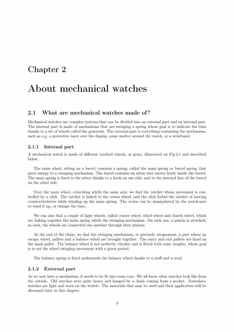
2.1 What are mechanical watches made of?Mechanical watches are complex systems that can be divided into an external part and an internal part.The internal part is made of mechanisms that are swinging a spring whose goal is to indicate the timethanks to a set of wheels called the geartrain. The external part is everything containing the mechanism,such as e.g. a protective layer over the display, some matter around the watch, or a wristband.
2.1.1 Internal partA mechanical watch is made of different toothed wheels, or gears, illustrated on Fig.2.1 and describedbelow.
The main wheel, sitting on a barrel, contains a spring, called the main spring or barrel spring, thatgives energy to a swinging mechanism. The barrel contains an arbor that moves freely inside the barrel.The main spring is fixed to the arbor thanks to a hook on one side, and to the internal face of the barrelon the other side.
Over the main wheel, coïnciding whith the same axis, we find the ratchet whose movement is con-trolled by a click. The ratchet is linked to the crown wheel, and the click forbid the ratchet of movingcounterclockwise while winding up the main spring. The crown can be manipulated by the watch-userto wind it up, or change the time.
We can also find a couple of light wheels, called center wheel, third wheel and fourth wheel, whichare linking together the main spring whith the swinging mechanism. On each one, a pinion is attached;as such, the wheels are connected one another through their pinions.
At the end of the chain, we find the swinging mechanism, or precisely escapement, a part where anescape wheel, pallets and a balance wheel are brought together. The entry and exit pallets are fixed onthe main pallet. The balance wheel is not perfectly circular and is fitted with some weights, whose goalis to set the wheel swinging movement with a given period.
The balance spring is fixed underneath the balance wheel thanks to a staff and a stud.
2.1.2 External partAs we now have a mechanism, it needs to be fit into some case. We all know what watches look like fromthe outside. Old watches were quite heavy and hanged by a chain coming from a pocket. Nowadays,watches are light and worn on the wristle. The materials that may be used and their application will bediscussed later in this chapter.
3

Figure 2.1: Wheels in a mechanical watch
2.2 How do mechanical watches work?To initiate the watch movement, the user has to wind up its watch. This has for effect to wind up themain spring which contracts itself and gets more strain energy.
As the spring would like to get back to its initial position, it pulls the barrel drum that, in turn, trans-mits a radial force to the geartrain. From one wheel to another, the force transmits to the escapement.
The escape wheel is not shaped as every other toothed wheels. It has a design that makes it movingonly step by step. In a first move, the escape wheel touches the first pallet, called the exit pallet, whichin turn moves the main pallet, pushing the roller on one side and so swinging the balance wheel. Whilethe balance moves, the exit pallet blocks the escape wheel. As the balance wheel is linked to its spring,it gets back, pushes on the main pallet on the other side while at the same time the escape wheel turnsand gives another pulse.
The main pallet moves the balance wheel back and forth : the movement we just created gets self-sustained at a given period. One can hear the pallet contact with the roller through the "tic, tac" sound,familiar with watches or even cheap clocks.
2.3 Review of materials in nowadays watchesEarly watches are mainly made of several kind of steel. For coatings, a thin layer of stainless steel canbe deposited.
Watches nowadays make a big use of materials such as plastic and alloys. We can find other materials,sometimes precious and expensive for crucial mechanical parts. Wristbands are very different from onewatch to another : It can be made of leather, steel, plastic or even cardboard for low-value watches.
The mechanism is mainly made of metallic parts, the matter depending on the quality and/or themanufacturer. For springs [1], we usually use low-carbon steels or alloys based on Nickel, Cobalt or Ti-tanium (e.g. Elgiloy, a Cr-Co-Ni-Fe-Mo-based alloy, or Nivarox, a Fe-Ni-Cr-Ti-Al-alloy). For gears [2],we use cast-iron or low-carbon steel alloys (hardened and tempered) because they are easily machinable;we can also use Brass, because it absorbs the gears noise.
4

To have watches looking more precious, manufacturer sometimes add some jewelry artifices, that canrange from low-carats jewel to beautiful rubys.
The display are made of a glasses or polymers, which one having their qualities and defaults. Glassesare tough but fragile and can be easily ripped, while polymers can resist to shocks and ripping if attentionis given in the design process.
2.4 Innovative materialsThe quest for optimum materials for watch components is one of the branches of research at the forefrontof watch innovations. Watch manufacturers are always on the search for exciting new materials. Thegoal of lots of these material innovations is to minimize the weight and friction losses without the use ofoil which implies greater accuracy in mechanical movement and at the same time longer durability.
Several watch brands, such as Ulysse Nardin, Omega and Patek Philippe, produce watches with siliconpieces. For instance, Patek Philippe developed Silinvar (a patented substance derived from oxidising theconstituents of pure silicium in a vacuum) to make several timepieces: an escape wheel that requires nolubrification, a balance spring which improves isochronism of the movement and an escapement whichhas a more efficient power transmission.
Patek Philippe has recently developed a new balance in gold and Silinvar. This choice of materialsresults from two criteria to optimize in a balance: to be as light as possible and to have a big iner-tia. Its chassis is etched in Silinvar for its low density while two inertial masses made in 24K gold areput at the periphery. This is, we minimize the mass near the axis of the balance and we increase its inertia.
Moreover, due to the high density of gold, the volume, and so the aerodynamic drag, can be minimized.But it requires an excellent manufacture precision. Indeed, by concentrating the mass on the outside ofthe balance, a default of mass positioning, i.e. an unbalance, would generate a harmonic excitation ofhigh amplitude and would result in an unwanted dynamic response.
The key physical properties of Silinvar are :
• Its low density (3.6 times less density than conventional balance materials);
• Homogenity (uniform mass distribution);
• Antimagnetism;
• Resistance to corrosion;
• Hardness;
• Resistance to shocks;
• Manufacturing precision;
• Non susceptibile to temperature fluctuations.
From the above, this material is really the must for manufacturing timepieces.Another watch manufacturer, Omega, has also created a balance spring in silicon. The balance spring
is a critical element for precision. Indeed, it is extremely sensitive to shocks as well as to magnetic fields.Silicon allows to increase shock absorbency and stability while increasing resilience. It also eradicates theeffects of any magnetic fields. So, this material contributes to the higher rate accuracy, lifespan, efficiencyand reliability of watches.
Other brands target the lightness of watches. For instance, Richard Mille has developed a new ma-terial, called Alusic, to produce the case. It is a super light hybrid material – aluminum AS7G, silicon
5

and carbon used for the production of ultra-light satellites, and another aluminum-lithium alloy for thetourbillion skeleton movement.
Finally, Audemar Piguet use carbon for its lightness and shock resistance.
Even if these materials are very innovative and functional, the traditional ones are still favored inwatch productions for several reasons. First, steel pinions and brass wheels still provide the best frictioncoefficient. Secondly, these materials are familiar to watch manufacturers and watch repairers.
6
Chapter 3
Materials selection
3.1 IntroductionIn this study-case, we will focus on the main parts contained in mechanical watches.
We will therefore consider the following parts, respectively springs (mainspring and balance wheel),wheels (gearbox, escapement, barrels and so on), pallets, shafts (wind-up mechanism), case, gaskets,hands (hours and minutes), dial and wristbands.
3.2 SpringsFor the springs, our objective is to store as much energy as possible without failure while minimizing cost.
On one hand, the deformation energy of a spring is given by W =∫
σεdV . On the other hand, thespring is submitted to the constraint :
σ =6M
bt2≤ σf
where M is the couple applied on the spring, b the width and t the thickness. We can also deduce a freevariable ε = σf
E .
Combining these three last expressions, it comes :
W =∫
σ2f
EdV =
σ2f
E
∫dV =
σ2f
E
m
ρ
Therefore, we have to maximise one of the following expression :• the elastic energy per mass unit W = σ2
f
ρE
• the elastic energy per volume unit W = σ2f
E .
The cost of the spring can writes C = ρcV where C is the total material cost, ρ the density of thematerial, V the volume of the spring and c the material cost per mass unit.
Since the stored energy U is assumed known, we can isolate the volume V = UEσ2
fso that our expression
becomes :
C =ρcUE
σ2f
=ρcE
σ2f︸︷︷︸
material
U︸︷︷︸energy
7

Thus, we have to maximize :
W =σ2
f
E(3.1)
which gives in logarithmic scales :
log W = 2 log σf − log E
⇔ log E = 2 log σf − log W
⇔ y = 2x− log W
From the last equation, we can draw an Ashby diagram in the software CES. This diagram showswhich materials are maximizing the deformation energy with respect to the Young’s modulus (see Fig.3.1).
We also have to minimize the following expression :
M =ρcE
σ2f
(3.2)
which gives in logarithmic scales :
log M = log(ρcE)− 2 log σf
⇔ log(ρcE) = 2 log σf + log M
⇔ y = 2x + log M
Once again, we represent in CES an Ashby diagram that shows the materials which are minimizingthe cost with respect to the stored energy (see Fig. 3.2).
By taking, say, the ten first materials suggested by CES and comparing them using the AND-method(see Tab. 3.1) with a weighted factor of 1, we have to convert the maximum criteria for stored energyinto a minimum criteria. This is simply done by inverting the maximum criteria : M1 = 1
W = Eσ2
f.
From Tab. 3.1, we see that the low carbon-steel alloys fullfit the imposed requirements. If we wantto maximize the internal energy, we will preferabily choose Titanium alloys or Nickel super-alloys, butthey are more expensive and difficult to manufacture. All polymers, such as CFRP or GFRP, must beeliminated because their deformation energy acts in a non-linear way – that’s a behavior we would liketo avoid in mechanical watches.
Therefore, we will choose low-carbon steel-based springs. This material is rather cheap, easy to man-ufacture and has a high fatigue strength limit (about 400 MPa for 107 cycles).
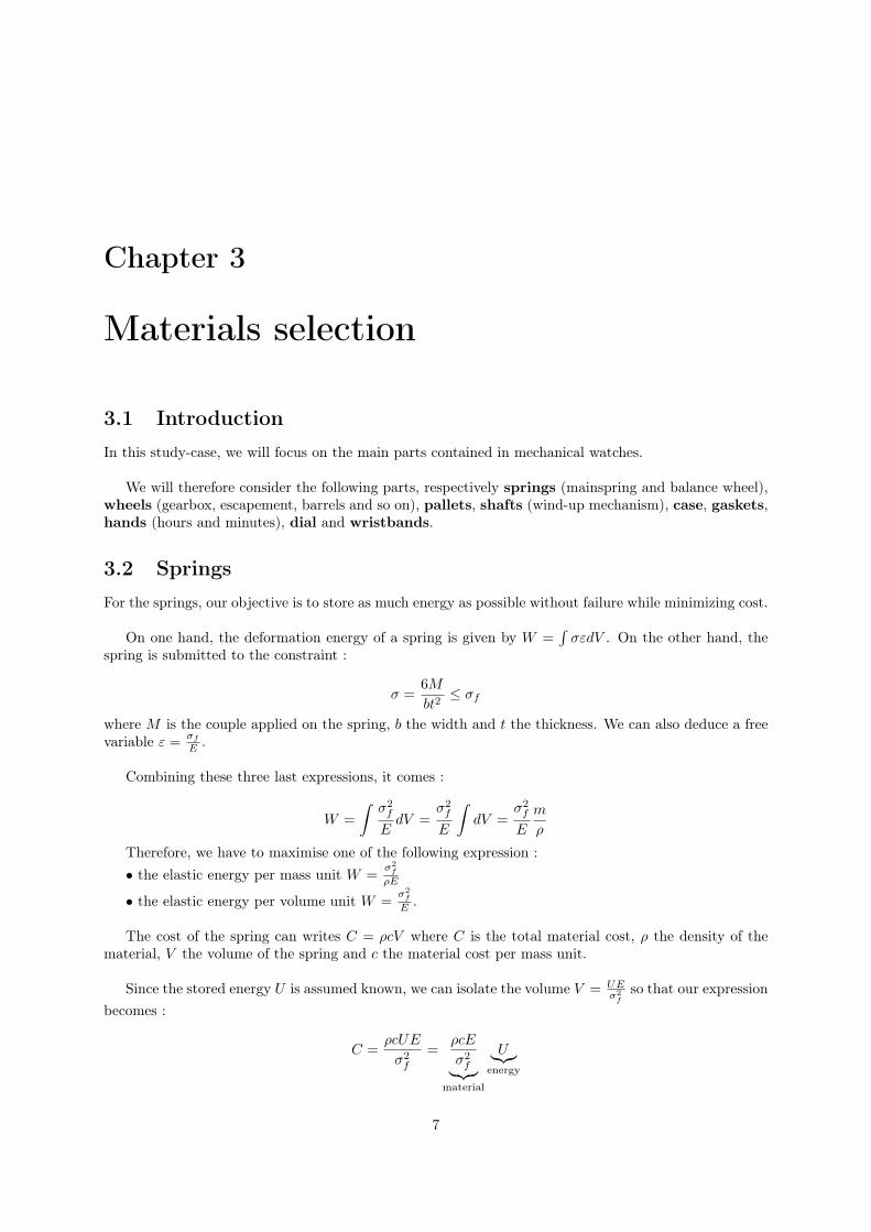
If we take into account the cost condition in addition to energy, machinability and fatigue strengthconditions, we get another Ashby diagram illustrated on Fig. 3.3.
3.3 WheelsIn this section, we will discuss about the different wheels found on the watch, including the gearbox andthe spring barrel.
The objectives to satisfy are multiple :
• Minimize the cost;
• Resist to shocks;
8

Figure 3.1: Materials maximizing the stored energy without any other constraint
Figure 3.2: Materials minimizing the cost without any other constraint
9

Mat
eria
lsρ[k
gm
3]
E[G
Pa]
σf
[GPa]
c[U
SD
kg
]M
1=
E σ2 f
M2
=ρcE
σ2 f
M1a
M2a
Man
d
Tit
aniu
mal
loys
4596
115
0.94
970
127.
694.
1081
0.01
580.
502
7.93
110−
3
CFR
P15
4910
20.
7642
176.
591.
1499
0.02
180.
141
3.07
410−
3
Alu
min
ium
-allo
ys26
9370
0.09
31.
6680
93.4
3.61
811
0.44
24.
4210−
1
Hig
hca
rbon
-ste
elal
loys
7850
207
0.68
10.
7644
6.35
0.26
60.
0551
0.03
31.
8181
0−3
Low
carb
on-s
teel
allo
ys78
5021
10.
775
0.85
351.
30.
234
0.04
340.
029
1.26
10−
3
GFR
P18
5720
0.14
520
.38
951.
253.
6001
0.11
750.
440
5.17
10−
2
Stai
nles
sst
eel
7846
199
0.41
26.
8411
72.4
6.29
0.14
490.
769
1.11
10−
1
Bro
nze
8746
860.
224
3.74
1714
.05.
6064
0.21
180.
685
1.45
10−
1
Bra
ss82
1999
0.21
82.
5420
83.2
4.34
890.
2574
0.53
11.
3710−
1
Nic
kel-b
ased
allo
ys81
8819
20.
755
29.6
733
6.83
8.18
280.
0416
14.
1610−
2
Tab
le3.
1:T
his
tabl
eso
rts
the
ten
best
-sui
ted
mat
eria
lsfo
rsp
ring
s.M
an
dha
sto
bem
inim
ized
.
10
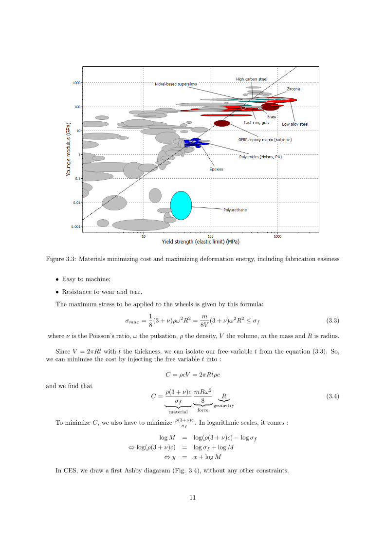
Figure 3.3: Materials minimizing cost and maximizing deformation energy, including fabrication easiness
• Easy to machine;
• Resistance to wear and tear.
The maximum stress to be applied to the wheels is given by this formula:
σmax =18(3 + ν)ρω2R2 =
m
8V(3 + ν)ω2R2 ≤ σf (3.3)
where ν is the Poisson’s ratio, ω the pulsation, ρ the density, V the volume, m the mass and R is radius.
Since V = 2πRt with t the thickness, we can isolate our free variable t from the equation (3.3). So,we can minimise the cost by injecting the free variable t into :
C = ρcV = 2πRtρc
and we find that
C =ρ(3 + ν)c
σf︸ ︷︷ ︸material
mRω2
8︸ ︷︷ ︸force
R︸︷︷︸geometry
(3.4)
To minimize C, we also have to minimize ρ(3+ν)cσf
. In logarithmic scales, it comes :
log M = log(ρ(3 + ν)c)− log σf
⇔ log(ρ(3 + ν)c) = log σf + log M
⇔ y = x + log M
In CES, we draw a first Ashby diagaram (Fig. 3.4), without any other constraints.
11

Figure 3.4: Materials minimizing cost for gears (without constraints)
We would also like to maximize the resistance to shocks :
W = Gc =K2
c
E(1 + ν)
and in logarithmic scales :
log W = 2 log(KIc)− log(E(1 + ν))⇔ y = 2x− log GIc
We get a second diagram (Fig. 3.5) in CES.
We look at the eight materials chosen by CES, and compare them in the table 3.2 using the AND-method with weight factor of 1. For this, we have to convert the maximum criterion of resistance toshoks into a minimum one. This is simply done by inverting the maximum criterion M2 = 1
W = E(1+ν)K2
c.
We see on table 3.2 that the most convenient material is low-carbon steel. But if we consider the re-sistance to shocks for sole criterion, Brass is the most suitable material. We impose a minimum hardnessof 150 HV (Vickers Pyramid Number) to satisfy the wear and tear tolerences. All the listed materials,excepted Aluminium alloys, satisfy these conditions.
By combining the two previous diagram, we draw the final graph 3.6 with all constraints and manu-facturing limitations.
12

Figure 3.5: Materials maximizing the resistance to shocks for gears (without constraints)
Figure 3.6: Materials minimizing cost, maximizing resistance to shocks and easily machinable
13

Mat
eria
lρ[k
gm
3]
ν[-]
c[U
SD
kg
]σ
f[G
Pa]
E[G
Pa]
Kc
[GP
am
1/2]
M1
=ρ(3
+ν)c
σf
M2
=E
(1+
ν)
K2 c
M1a
M2a
Man
d
Low
allo
yca
rbon
-ste
el78
500.
290.
846
0.77
521
10.
0529
2.81
91O
49.
717
104
5.76
710−
24.
001
10−
12.
307
10−
2
Hig
hca
rbon
stee
l78
500.
290.
759
0.68
120
70.
0498
2.87
610
410
.769
104
5.88
410−
24.
434
10−
12.
609
10−
2
Med
ium
carb
onst
eel
7850
0.29
0.70
40.
524
208
0.03
323.
469
104
24.2
8610
47.
097
10−
21
7.09
710−
2
Low
carb
onst
eel
7850
0.29
0.66
50.
314
207
0.05
85.
467
104
7.95
610
41.
119
10−
13.
276
10−
13.
666
10−
2
Alu
min
ium
allo
ys26
930.
341.
688
0.09
370
0.03
316
.387
104
8.58
310
43.
353
10−
13.
534
10−
11.
185
10−
1
Zinc
allo
ys58
860.
321.
214
0.19
082
0.02
712
.488
104
15.5
0610
42.
555
10−
16.
385
10−
11.
631
10−
1
Bra
ss82
190.
352.
537
0.21
899
0.04
232
.003
104
7.43
510
46.
548
10−
13.
061
10−
12.
004
10−
1
Bro
nze
8746
0.35
3.73
60.
224
860.
038
48.8
7710
48.
007
104
13.
297
10−
13.
297
10−
1
Tab
le3.
2:T
his
tabl
eso
rts
the
eigh
tbe
st-s
uite
dm
ater
ials
for
gear
s.T
hem
ost
suit
able
has
tom
inim
ize
Man
d.
14

3.4 PalletsThe main pallet must resist to shocks and bending, while being as cheap as possible.
On one hand, maximizing the resistance to shocks and cracking implies maximizing the yield strengthW1 = σf and the fracture toughness W2 = KIc.
On the other hand, we have to minimize the deformation δ given by:
δ =FL3
C1EI(3.5)
where F is the force, L the length, c1 a tabulated constant, E the Young’s modulus and I the secondmoment of inertia.
Since
σmax =FL2
I≤ σf
we can isolate I (our free variable) and replace it in the equation (3.5). So, we have to find the miminumfor δ, with
δ =σfL
c1E
We have M1 = σf
E which, in logarithmic scales, is written
log E = log σf − log M1
To minimize the cost C = ρcV = ρcL√
12I, we replace I by the expression 3.5. We obtain:
C =ρc√
σf︸ ︷︷ ︸material
√12 F︸ ︷︷ ︸force
L2︸︷︷︸geometry
or, in logarithmic scales:log σf = 2 log(ρc)− 2 log M2
where M2 = min(C).
In CES, we plot an Ashby diagram (Fig. 3.7) for all constraints, including for machinability.
To compare the materials bewteen them, we list them in table 3.3. For this purpose, we transformthe minimum criteria into maximum ones: W3 = 1
M1= E
σfand W4 = 1
M2=√
σf
ρc .
It appears that low-carbon steel is the most convenient material. Wood is eliminated because thismaterial is hardly isotropic and doesn’t resist much to cracks. Glass is also evicted because it is toobrittle, while not fulfilling the everyday-use requirements. So, pallets in watches are most of the timemade of metals or polymers.
3.5 ShaftsThe wind-up mechanism is made of a shaft and a crown wheel. The shaft must withstand the torsionalcouple applied thanks to the crown wheel. Once again, minimizing the cost will be required.
Stress in torsion is written asσ =
4Tf
πR3≤ σf
15

Mat
eria
lρ[k
gm
3]
c[U
SD
kg
]E
[GP
a]
σf
=W
1[G
Pa]
Kc
=W
2[G
Pam
1/2]
W3
W4
W1a
W2a
W3a
W4a
Wan
d
Low
allo
yst
eel
7850
0.84
621
10.
775
0.05
2927
2.29
1.32
610−
41
0.91
20.
339
0.80
20.
248
Hig
hca
rbon
stee
l78
500.
759
207
0.68
10.
0498
304.
421.
386
10−
40.
879
0.85
90.
379
0.83
80.
240
Low
carb
onst
eel
7850
0.66
520
70.
314
0.05
8065
9.88
1.07
410−
40.
405
10.
822
0.64
90.
216
Alu
min
ium
allo
ys26
931.
613
740.
241
0.02
7130
6.39
1.13
010−
40.
311
0.46
70.
382
0.68
30.
038
Cas
tir
on71
490.
654
172
0.41
20.
0345
417.
981.
373
10−
40.
532
0.59
50.
521
0.83
00.
137
Mag
nesi
umal
loys
1710
5.47
444
0.21
70.
0147
204.
610.
498
10−
40.
280
0.25
30.
255
0.30
10.
0054
Bam
boo
693
1.72
917
0.03
90.
0059
441.
371.
654
10−
40.
050
0.10
20.
550
10.
0028
Gla
ssce
ram
ics
2638
5.06
684
0.10
50.
0016
802.
540.
243
10−
40.
135
0.02
81
0.14
70.
0005
6
Tab
le3.
3:T
his
tabl
eso
rts
the
eigh
tbe
st-s
uite
dm
ater
ials
for
palle
ts.
The
mos
tsu
itab
leha
sto
max
imiz
eW
an
d.
16
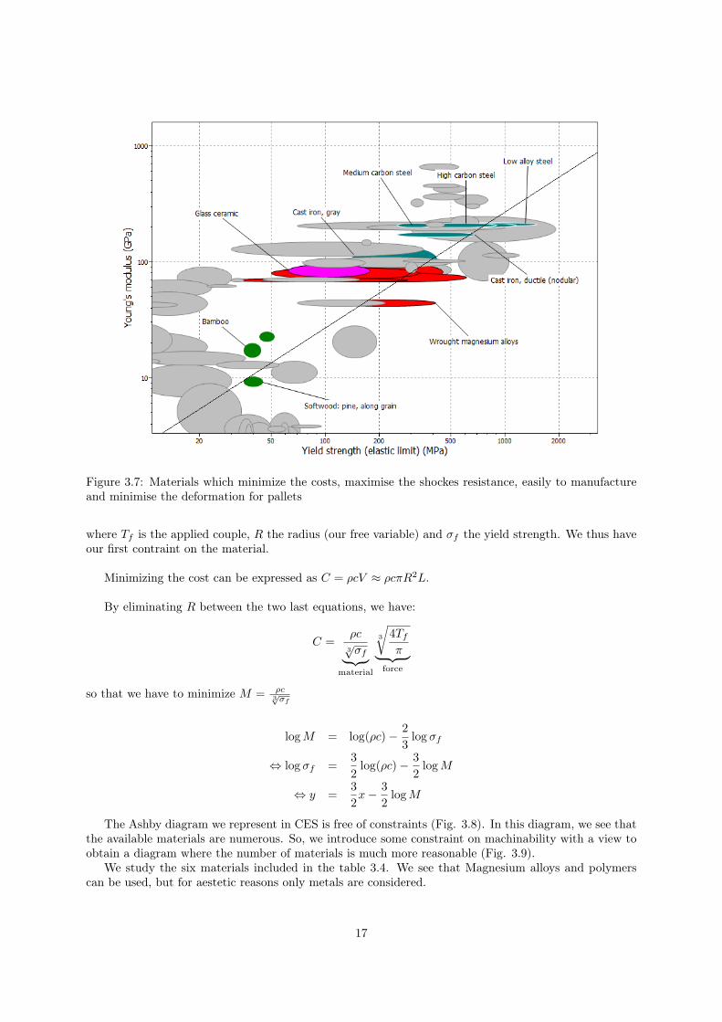
Figure 3.7: Materials which minimize the costs, maximise the shockes resistance, easily to manufactureand minimise the deformation for pallets
where Tf is the applied couple, R the radius (our free variable) and σf the yield strength. We thus haveour first contraint on the material.
Minimizing the cost can be expressed as C = ρcV ≈ ρcπR2L.
By eliminating R between the two last equations, we have:
C =ρc
3√
σf︸ ︷︷ ︸material
3
√4Tf
π︸ ︷︷ ︸force
so that we have to minimize M = ρc3√σf
log M = log(ρc)− 23
log σf
⇔ log σf =32
log(ρc)− 32
log M
⇔ y =32x− 3
2log M
The Ashby diagram we represent in CES is free of constraints (Fig. 3.8). In this diagram, we see thatthe available materials are numerous. So, we introduce some constraint on machinability with a view toobtain a diagram where the number of materials is much more reasonable (Fig. 3.9).
We study the six materials included in the table 3.4. We see that Magnesium alloys and polymerscan be used, but for aestetic reasons only metals are considered.
17

Figure 3.8: Materials which minimize the costs without other constraints for the crown wheel.
Figure 3.9: Materials which minimize the costs with some condition of the manufactoring facilities forthe crown wheel.
18

Material ρ[ kgm3 ] c[USD
kg ] σf [MPa] M Ma
High carbon steel 7850 0.759 681.18 76.96 0.189Low alloy steel 7850 0.846 774.60 78.74 0.193
Aluminium alloys 2693 1.837 128.45 188.61 0.463Zinc alloys 5886 1.214 189.74 216.40 0.531
PLA 1230 3.311 53.67 286.23 0.703Magnesium alloys 1710 5.474 217.14 407.29 1
Table 3.4: This table sorts the six best-suited materials for shafts. The most suitable has to minimize Mor Ma.
Material E [GPa] ν [−] H [V H] K [GPam1/2] W Wa
Stainless steel 202 0.275 339 0.3015 0.1197 1Nickel alloys 130 0.285 367 0.1342 0.0396 0.331Gold alloys 90 0.330 248 0.1342 0.0374 0.312
HM carbon fiber 6 0.005 15 0.0217 0.0012 0.010Fluoro elastomer 3.1 10−3 0.4945 15 9.397 10−4 0.0028 0.023
Table 3.5: This table sorts the five best-suited materials for watch cases. The most suitable has tomaximize W or Wa.
3.6 CasingsThe casing has to withstand shocks, corrosion and UV-rays.
To select a material fulfilling these conditions, we have to maximize both the hardness and theresilience :
W = HGIc = HK2
Ic
E(1 + ν)
and, in logarithmic scales,
log W = log(HK2Ic)− log(E(1 + ν))
⇔ log(E(1 + ν)) = log(HK2c )− log W
⇔ y = x− log W
The corresponding Ashby diagram (Fig. 3.10) shows that metals and polymers have the best per-formance index. If we apply some limits, such as resistance to corrosion and UV-rays, we modify thediagram by removing undesirable materials (Fig. 3.11).
We studied five materials in the table 3.5. All of them resist to corrosion and UV-rays, and all areeasily machinable.
We see that stainless steel perfectly fits the given conditions. Nevertheless, we also see on the diagramsome unconventional materials like elastomer or carbon fibers, in addition to polymers, corks and preciousmetals (e.g. Gold, Titanium, Nickel, Silver, Tantalum).
Another approach is to deposit a non-corrosive metal on the casing, giving resistance to corrosionthrough a thin layer of, say, Gold, Chrome, Zinc or polymer.
19

Figure 3.10: Materials maximizing resistance to shocks (without other constraints) for casings.
Figure 3.11: Materials maximizing resistance to shocks (with conditions on machinability, corrosion andUV resistance) for casings.
20

Figure 3.12: Materials which maximise the tight condition and which have some fabrication constraintsand are corrosion resistance.
3.7 Gaskets
To be hermetic, the materials suited for gaskets must maximize√
σ3f
E and 1E , such that, in logarithmic
scales,
log W =32
log σf − log E
⇔ log E =32
log σf − log W
⇔ y =32x− log W
In CES, We represent an Ashby diagram including some fabrication conditions and resistance to corrosion(Fig. 3.12).
We list in the table 3.6 the materials suggested by CES. We see that polychloroprene is widely thebest-suited one.
3.8 HandsThe hands should not bend, so we must find materials limiting the deflection δ.
Under the constraint
σ =L2F
4I≤ σf
21

Material E [GPa] σf [GPa] W1 =σ
3/2f
E W1E2 W1a W2a Wand
Polychloroprene 0.0019 0.017 1.1877 537.22 1 1 1PVC-elastomer 0.0044 0.0201 0.6415 224.77 0.540 0.418 0.226Polyethylene 0.0024 0.0125 0.5699 408.25 0.480 0.760 0.365PVC-flexible 0.0065 0.0135 0.2418 154.30 0.204 0.287 0.059
Silicone 0.0158 0.0092 0.0555 63.246 0.047 0.118 0.0055TPO 0.0198 0.0059 0.0228 50.577 0.019 0.094 0.0018
Table 3.6: This table sorts the five best-suited materials for gaskets. The most suitable has to maximizeWand.
the deflection is written
δ =FL3
8C1EI
so that the free variable is I.We thus find that
δ =Lσf
2C1E=
σf
E︸︷︷︸material
L
2C1︸︷︷︸geometry
where L is the length of the hands, σf the yield strength, c1 a tabulated constant and E the Young’smodulus.
Another point to take into account is minimizing the mass of the two hands. The mass is given bym = ρV ≈ ρb2L, and since I = b4
12 , we obtain the following equations :
m =ρ√(σf )︸ ︷︷ ︸
Material
√3F︸ ︷︷ ︸
Force
L2︸︷︷︸Geometry
We have to minimize the following expressions :
M1 = σf
E (3.6)
M2 =ρ√(σf )
(3.7)
or in logarithmic scales :
log E = log σf − log(M1)log σf = 2 log ρ− 2 log M2
We plot an Ashby diagram in CES, including some machinability constraints (Fig. 3.13).
We will now draw up the performance table 3.7 for some materials selected by CES. Since M1 is muchmore important than M2, we attribute respectively a weight factor of 0.75 and 0.25. We see that Nickelis the best-suited material, but Aluminium alloys, Brass or Stainless steel can also be used to reduce thecost.
3.9 Watch glassThe glass has to withstand wear and scratch and, moreover, must resist to shocks and corrosion. Theglass must obviously be transparent.
22

Figure 3.13: Materials minimizing mass and deflection of the hands, including machinability constraints.
Material E [GPa] ρ [kg/m3] σf [GPa] M1 = σf
E M2 = ρ√σf
M1a M2a Mand
Cast Mg alloys 44 1809 0.133 2.8 10−3 1.81 103 0.72 0.10 1.39Nickel 204 8890 0.251 1.2 10−3 17.74 103 0.31 1 0.42
Stainless steel 199 7846 0.412 2.1 10−3 12.22 103 0.54 0.69 1.69Cast Al alloys 80 2693 0.129 1.6 10−3 7.51 103 0.41 0.42 0.64
Brass 99 8219 0.218 2.2 10−3 17.60 103 0.56 0.99 0.65Nickel alloys 192 8188 0.755 3.9 10−3 9.42 103 1 0.53 1.17
Low alloy steel 211 7850 0.775 3.7 10−3 8.92 103 0.95 0.50 1.14
Table 3.7: This table lists the best-suited materials for hands. Mand = M3/41a M
1/42a is minimized.
23

Figure 3.14: Materials maximizing resistance to shocks, including some machinability constraints forwatch glasses.
We have to maximise the same function as seen in section 3.6:
W =HK2
c
E(1 + ν)
Here, we introduce other constraints such as transparency or machinability. In an Ashby diagramcorresponding to these conditions, we find some materials that may be appropriate (Fig. 3.14).
In the table 3.8, we list some interesting materials. It appears that P.E.T. (polyethylene triphosphate)seems to be the best-suited material; however, it is transparent only when the thickness is rather small.So, in practice [3], we use silica glasses or cellulose polymers. But the best available is a one crystal glass.
Material E [GPa] ν [−] H [V H] K [GPam1/2] W Wa
Silica glass 71 0.169 654 6.928 10−4 3.785 10−6 0.0402Soda-lime glass 70 0.215 461 6.205 10−4 2.088 10−6 0.0222
Ionomer 0.29 0.444 3.46 2 10−7 32.20 10−6 0.3424PET 3.38 0.388 17.83 5 10−7 94.03 10−6 1
Polyurethane 1.65 0.408 19.12 3 10−7 75.05 10−6 0.7981Cellulose polymers 1.79 0.410 12.25 2 10−7 12.14 10−6 0.1291
Polystyrene 1.77 0.393 12.06 8.775 10−4 3.773 10−6 0.0401
Table 3.8: This table lists the seven best-suited materials for the glasses. The most suitable has tomaximise W or Wa.
24

Figure 3.15: Materials maximizing resistance to shocks for wristbands.
3.10 WristbandsWristbands are usually made in two different ways: on one hand, they are made of a single piece ofpolymer or leather; on the other hand, they are an assembly of rigid materials – usually metals.
Wristbands have to withstand corrosion, shocks, UV-rays, tension forces and cracks. We thus have tomaximise:
W1 = σf and W2 =K2
c
E(1 + ν)
We obtain the figure 3.15 in CES which regroups a multitude of materials.
We regroup some materials in table 3.9, and fix the weight factors to 1. As such, We see that stainlesssteel is a good material for wristbands fabricated piecewise. We can also have medium-carbon steel, onwhich we deposit a thin protective layer made of Gold, Chrome or plastic. For a one-piece wristband, wechoose leather or polyurethane. In practise, we find Titanium, Leather, Nylon, Silver, Silicone, Rubberand some more. source:http://www.watchstyle.fr/vollmer2.htm visited the 20th November 7:43 pm.
25

Mat
eria
lE
[GP
a]
ν[−
]K
[GP
am
1/2]
W1
=σ
f[M
Pa]
W2
W1a
W2a
Wan
d
Leat
her
0.22
40.
155
0.00
397.
075.
808
10−
50.
013
10.
013
Pol
yure
than
e0.
008
0.49
40.
0003
35.7
10.
691
10−
50.
068
0.11
90.
0081
Stai
nles
sst
eel
199
0.27
00.
0964
412.
313.
676
10−
50.
787
0.63
30.
498
Med
ium
carb
onst
eel
208
0.29
00.
0332
523.
930.
412
10−
51
0.07
10.
071
Lead
allo
ys14
.866
0.44
00.
0158
181.
168
10−
50.
034
0.20
10.
0068
Zinc
allo
ys82
.462
0.28
70.
0265
189.
740.
659
10−
50.
362
0.11
30.
0409
Iono
mer
0.29
10.
444
0.00
211
.47
0.93
010−
50.
022
0.16
00.
0035
Tab
le3.
9:T
his
tabl
elis
tsth
ese
ven
best
-sui
ted
mat
eria
lsfo
rw
rist
band
s.T
hem
ost
suit
able
has
tom
axim
ize
Wan
d.
26

Chapter 4
Conclusion
During this in-depth study, we have seen that selecting materials is widely an iterative process. We firsthave to find what are the objectives for a piece with a given function. Than, we look after the biggestconstraints and identify a free variable for each one – which can be arduous.
From all the materials fulfilling the above requirements, we have yet to found materials that meet theuser expectations thanks to additional conditions, e.g. machinability, transparcency, heat-resistance.
Another difficulty are pieces manufactured in different ways, e.g. the wristband is usually made up ofseveral metallic pieces or by a single polymer piece.
∴
To conclude in some words, we can write that finding good materials for practical applications wasmuch more difficult than what we thought before. CES is a powerful tool to help us in this task, butselecting the best-suited material still needs to keep some critical mind. It is also interesting to have alook at what others did before for similar applications, because every material has his own properties,advantages and disadvantages.
27

Bibliography
[1] Y. Yamada and J. S. of Spring Engineers, Materials for springs. Springer, 2007.
[2] http://www.agroengineers.com/gears/Gear-Materials.shtml. Last visit : 17th November 2011 @ 5PM.
[3] http://www.grandoptical.com/Tout-sur-l-optique/Les-verres. Last visit : 18th November 2011 @ 9PM.
[4] D. Glasgow, Watch and clock making. Manuals of technol, Cassell, 1885.
[5] http://www.horlogerie-suisse.com. Last visit : 20th November 2011 @ 7 PM.
[6] http://en.wikipedia.com/Mechanical_watches. Last visit : 15th November 2011 @ 8 PM.
[7] http://www.archive.org/stream/watchandclockma00glasgoog#page/n10/mode/2up. Last visit :24th November 2011 @ 21 PM.
[8] http://www.youtube.com/watch?v=OiCPu0SjEW4. Short movie explaining how a mechanicalwatch works.
[9] http://www.horlogerie-suisse.com/watcharound/acier-laiton/Aciers-et-laitons_n_ont_pas_dit_leur_dernier_mot-10008.html. Last visit : 26th November 2011 @22 PM.
[10] http://www.omegawatches.com/fr/spirit/watchmaking/silicon-balance-spring. Last visit : 26thNovember 2011 @ 14 PM.
[11] http://journal.hautehorlogerie.org/fr/passion/from-the-workbench/patek-philippe-s-gyromax-isn-t-the-end-of-a-chapter-but-the-beginning-of-a-new-story-2651/. Last visit : 25th November 2011 @ 23PM.
[12] http://www.montres-de-luxe.com/Patek-Philippe-presente-le-nouveau-balancier-GyromaxSi-en-or-et-Silinvar_a5191.html. Last visit : 25th November 2011 @ 23 PM.
28