Embed Size (px)
Citation preview
Math and Feature Models of Assemblies
• Start of series of 5 classes on math/CAD models– basic matrix representations and Feature-based Design – constraint– variation
– assembly sequence analysis – Datum Flow Chain
Assy Models 9/16/2004 © Daniel E Whitney 1
Objectives of Assembly Modeling
• Provide a computer environment that permits top-down design of assemblies with a persistent database that captures the assembly as an assembly
• Should link to geometry creation (CAD, rule-generated)
• Should permit specification of Key Characteristics, constraints on location, datums and locators, and variation analysis for KCs using the assembly model
• Should permit assembly planning, vendor interfaces, ramp-up, and production support
Assy Models 9/16/2004 © Daniel E Whitney 2
Top-down and Bottom-up Design
• Top-down defines an assembly in this order: – major customer deliverables – chains of delivery through possible parts – main part mates and necessary features – detailed part geometry
• Bottom-up defines – the same things but in the reverse order – requires having some idea of final assembly layout first
• Top-down used to be the only way before CAD • CAD seems to encourage bottom-up
Assy Models 9/16/2004 © Daniel E Whitney 3
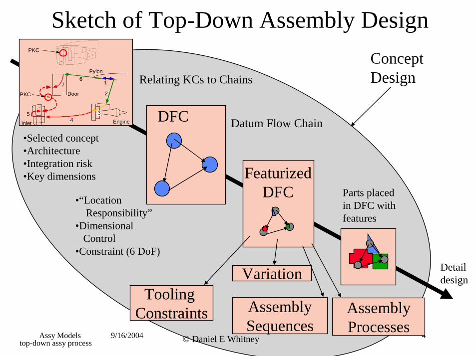
Sketch of Top-Down Assembly Design
49/16/2004
Tooling Constraints
Variation
Sequences
in DFC withResponsibility”
1
2
3 4
5
6 7
Pylon
EngineInlet
Door
PKC
PKC
Processes
design
Datum Flow Chain
Concept Design
Assy Models © Daniel E Whitney
DFC
Assembly
Parts placed
features
Featurized DFC •“Location
•Dimensional Control
•Constraint (6 DoF)
•Selected concept •Architecture •Integration risk •Key dimensions
Assembly
Detail
Relating KCs to Chains
top-down assy process
Goals of this Class
• Review basic math that relates adjacent coordinate frames
• Model assemblies as chains of frames • Attach these frames to “mating features” • Introduce feature based design for assembly
Assy Models 9/16/2004 © Daniel E Whitney 5
Basic Math
• Uses 4x4 matrices to relate adjacent frames
• Permits chaining together of parts – same math is used to describe robots
• The matrix contains a rotational part and a translational part
• The matrix is designed to translate first and then rotate so that rotation does not change position of new frame
• This matrix is a subset of a more general projection matrix that includes perspective
Assy Models 9/16/2004 © Daniel E Whitney 6
History of this Representation
• Basic to Kinematics (Denavit & Hartenberg) • Used to model assemblies in 1970s:
– S N Simunovic Master’s Thesis, MIT, 1972 – Edinburgh University AI Lab robot assembly 1976
• Used by CAD researchers – Steve Coons, 1960’s – Gossard and others, 1980s
• Used by CAD systems to locate surfaces wrt each other
Assy Models 9/16/2004 © Daniel E Whitney 7
Assy Models 9/16/2004 © Daniel E Whitney
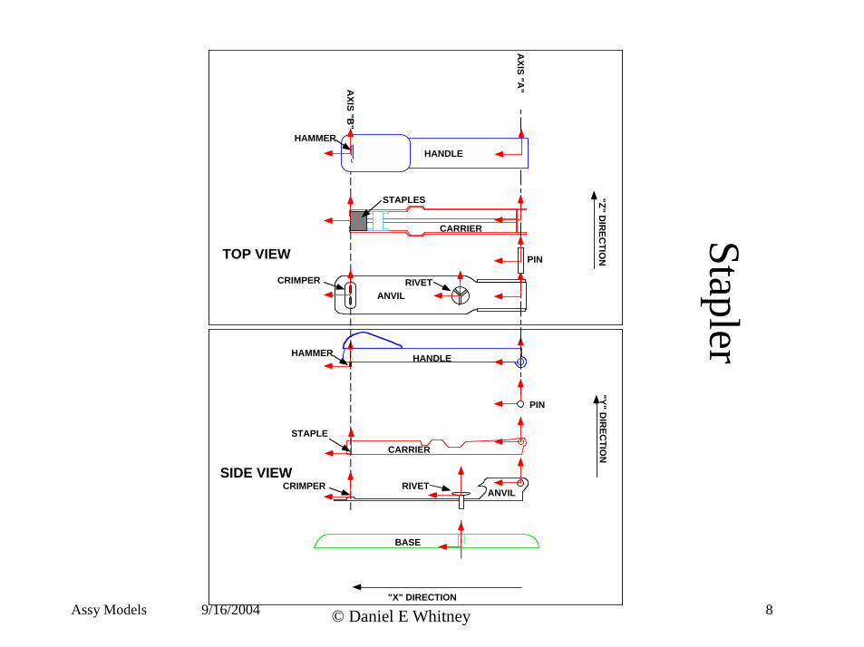
Stapler
HANDLEHAMMER
BASE
CARRIER
ANVIL
ANVIL
CARRIER
STAPLES
RIVET
RIVET
"X" DIRECTION
SIDE VIEW
TOP VIEW
HANDLE HAMMER
PIN
CRIMPER
CRIMPER
STAPLE
PIN
AXIS "A
" AXIS "B
"
"Y" DIR
ECTIO
N
"Z" DIR
ECTIO
N
8
Stapler Frames and KCs
Images removed for copyright reasons.Source:Figure 3-5 in [Whitney 2004] Whitney, D. E. Mechanical Assemblies: Their Design, Manufacture,
and Role in Product Development. New York, NY: Oxford University Press, 2004. ISBN: 0195157826.
Assy Models 9/16/2004 © Daniel E Whitney 9
Frames and Chains
• By following the arrows, you can travel from frame to frame
• On the previous slide, the anvil was chosen as the origin part, and the anvil-pin joint on the anvil was chosen as the location of the origin frame.
• All arrows go out from the origin frame
• You can travel from one end of a KC to the other by moving from frame to frame along the arrows, sometimes in arrow direction and sometimes in reverse
Assy Models 9/16/2004 © Daniel E Whitney 10
Basic Translation and Rotation
Image removed for copyright reasons.Source:Figure 3-6 in [Whitney 2004] Whitney, D. E. Mechanical Assemblies: Their Design, Manufacture,
and Role in Product Development. New York, NY: Oxford University Press, 2004. ISBN: 0195157826.
Translate first, then rotate
Assy Models 9/16/2004 © Daniel E Whitney 11
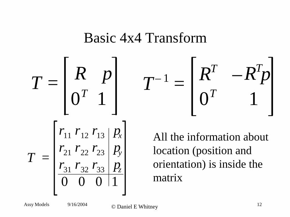
Basic 4x4 Transform
R p RT – RTpT – 1T = = 0T 1 0T 1
rr11 r12 r13
21 r22 r23T = r31 r32 r33
0 0 0
px
py
pz
1
All the information about location (position and orientation) is inside the matrix
Assy Models 9/16/2004 © Daniel E Whitney 12
Assy Models 13© Daniel E Whitney9/16/2004
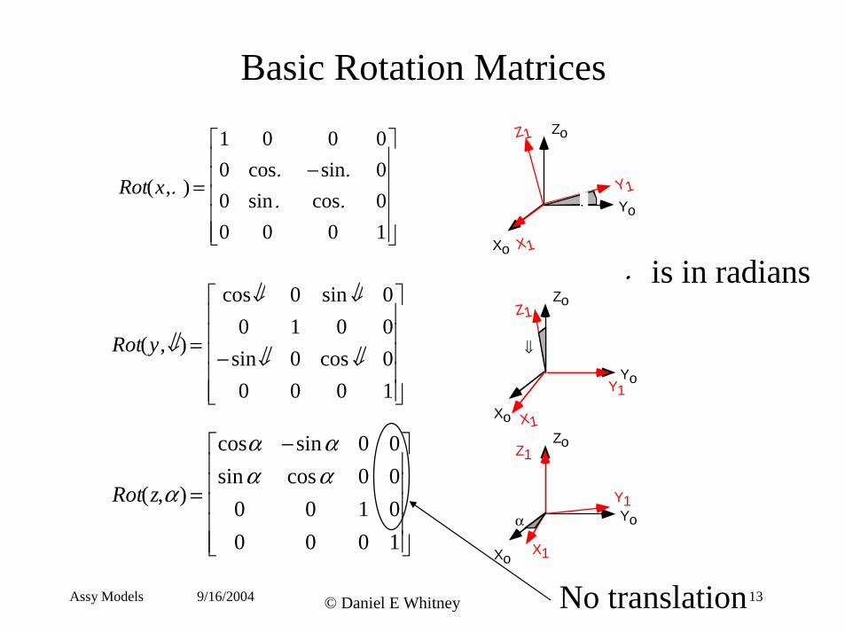
Basic Rotation Matrices
Xo
Yo
Zo
X1
Y1
Z1
.
Xo
Yo
Zo
X1
Y1
Z1
⇓
Rot(x,. ) =
1 0 0 00 cos. −sin. 00 sin . cos. 00 0 0 1
Rot(y,⇓) =
cos⇓ 0 sin⇓ 00 1 0 0
− sin⇓ 0 cos⇓ 00 0 0 1
Rot(z,α ) =
cosα −sinα 0 0sinα cosα 0 0
0 0 1 00 0 0 1
Xo
Yo
Zo
X1
Y1
Z1
α
No translation
. is in radians
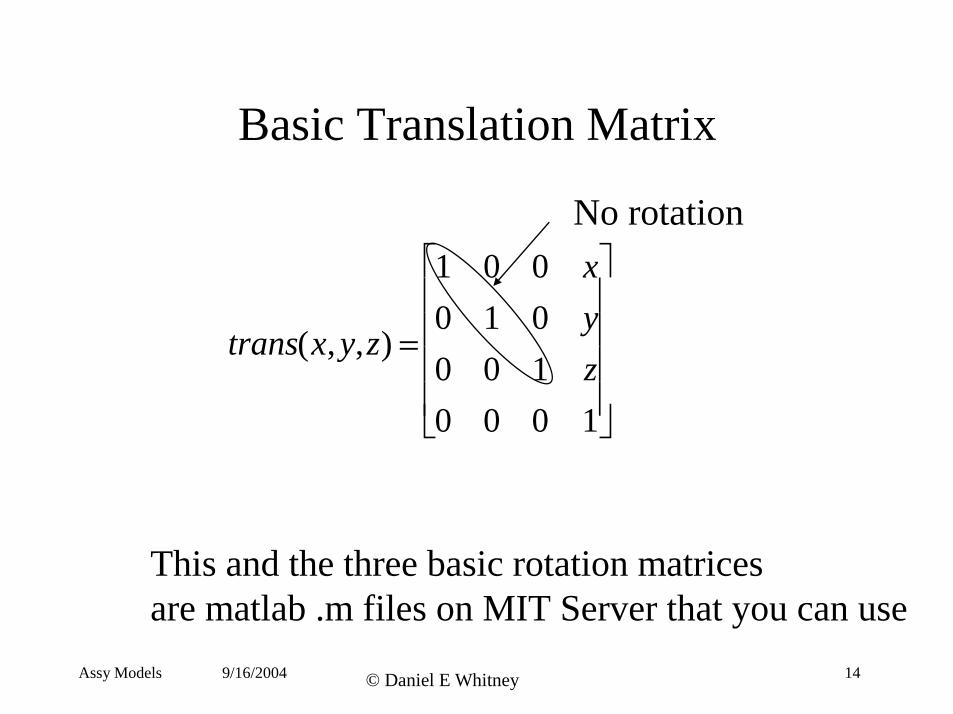
Basic Translation Matrix
No rotation 1 0 0 0 1 0 0 0 1
x
y
trans(x, y,z) = z
0 0 0 1
This and the three basic rotation matrices are matlab .m files on MIT Server that you can use
Assy Models 9/16/2004 © Daniel E Whitney 14
9/16/2004
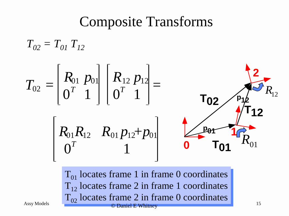
T01 locates frame 1 in frame 0 coordinatesT12 locates frame 2 in frame 1 coordinatesT02 locates frame 2 in frame 0 coordinates
Composite Transforms
T02 = T01 T12
R01 p01 R12 p12 =T02 = 0T 0T R
1
2
p01
p12T12
T02 121 1
R01R12 R01 p12+p01 0 T01 R010T 1
Assy Models
T01 T12 T02
© Daniel E Whitney
locates frame 1 in frame 0 coordinates locates frame 2 in frame 1 coordinates locates frame 2 in frame 0 coordinates
15
Assy Models 16© Daniel E Whitney9/16/2004
Transform Order is Important
TAB = TATB . TBA = TBTA
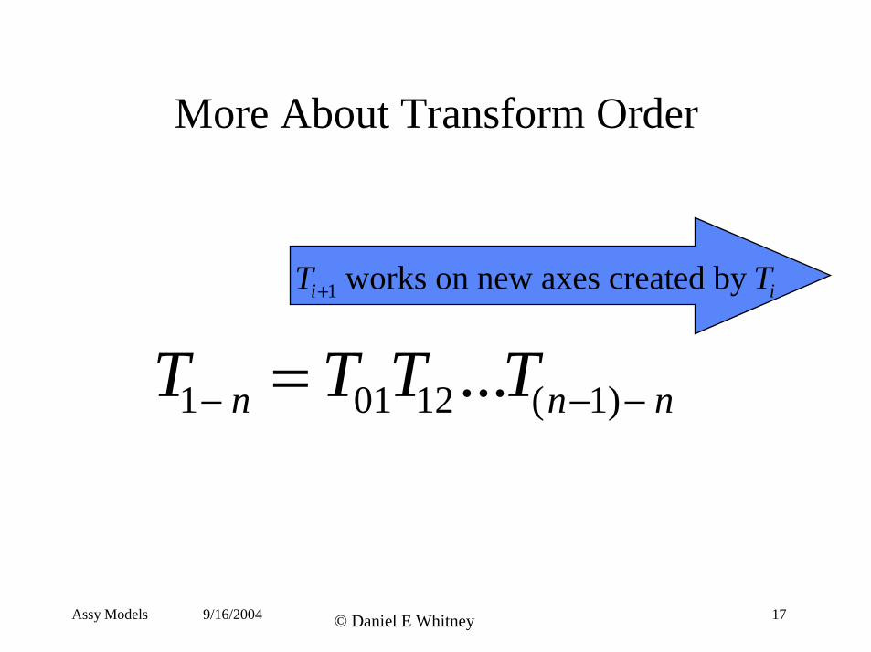
More About Transform Order
Ti +1 works on new axes created by Ti
T1− n = T01T12...T(n −1) − n
Assy Models 9/16/2004 © Daniel E Whitney 17
Nominal Mating of Parts
Images removed for copyright reasons.Source:Figure 3-17 in [Whitney 2004] Whitney, D. E. Mechanical Assemblies: Their Design, Manufacture,
and Role in Product Development. New York, NY: Oxford University Press, 2004. ISBN: 0195157826.
Assy Models 9/16/2004 © Daniel E Whitney 18
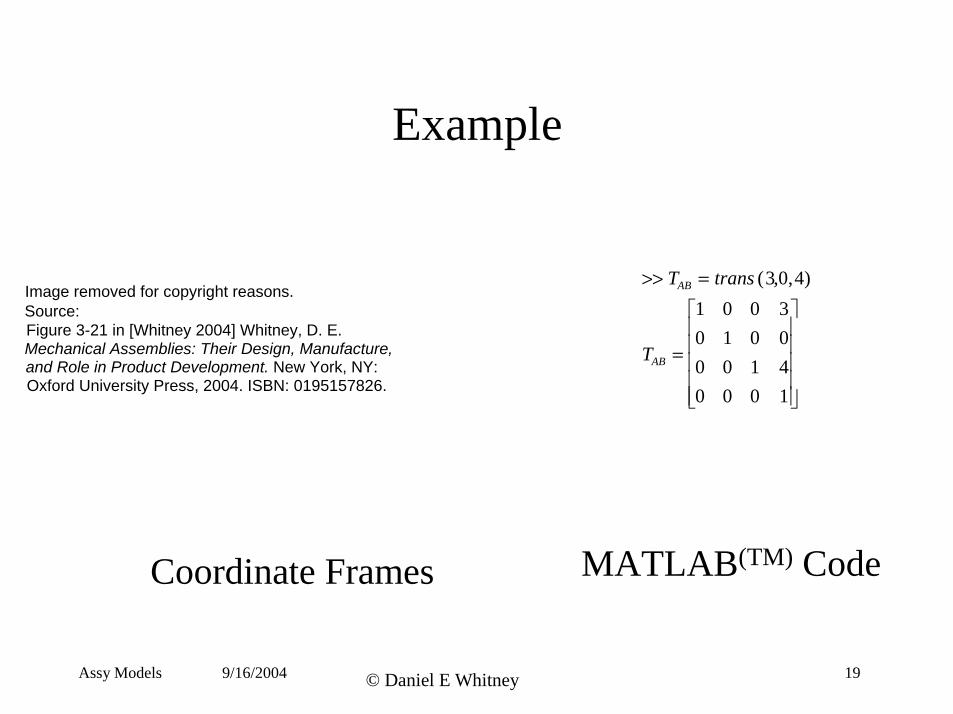
Example
>> TAB = trans (3,0,4) 1 0 0 0 1 0
3
=TAB 0 0 1 0 0 0
0
4
1
)Coordinate Frames MATLAB(TM Code
Assy Models 9/16/2004 © Daniel E Whitney 19
Image removed for copyright reasons.Source:Figure 3-21 in [Whitney 2004] Whitney, D. E. Mechanical Assemblies: Their Design, Manufacture, and Role in Product Development. New York, NY: Oxford University Press, 2004. ISBN: 0195157826.
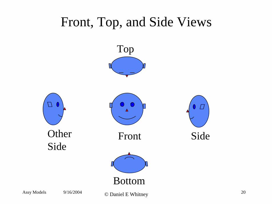
Front, Top, and Side Views
Top
Other Front Side Side
Bottom Assy Models 9/16/2004 © Daniel E Whitney 20
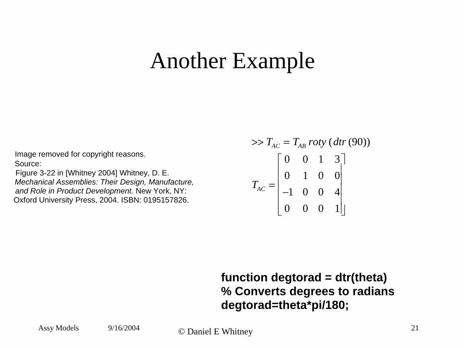
Another Example
>> TAC = TAB roty ( dtr (90))
0 0 1 3 0 1 0 0 −1 0 0 4 0 0 0 1
=TAC
Image removed for copyright reasons.Source:Figure 3-22 in [Whitney 2004] Whitney, D. E. Mechanical Assemblies: Their Design, Manufacture, and Role in Product Development. New York, NY: Oxford University Press, 2004. ISBN: 0195157826.
function degtorad = dtr(theta) % Converts degrees to radians degtorad=theta*pi/180;
Assy Models 9/16/2004 © Daniel E Whitney 21
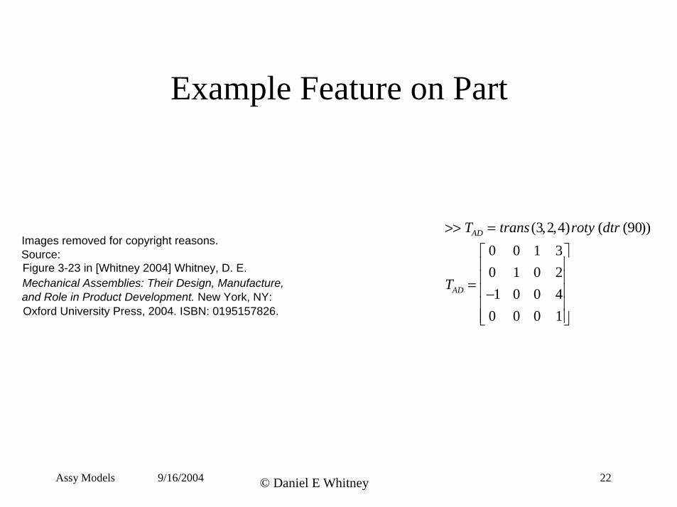
Example Feature on Part
>> TAD = trans (3, 2,4)roty (dtr (90))
0 0 1 3 0 1 0 2 −1 0 0 4 0 0 0 1
=TAD
Images removed for copyright reasons.
Source:
Figure 3-23 in [Whitney 2004] Whitney, D. E. Mechanical Assemblies: Their Design, Manufacture,
and Role in Product Development. New York, NY: Oxford University Press, 2004. ISBN: 0195157826.
Assy Models 9/16/2004 © Daniel E Whitney 22
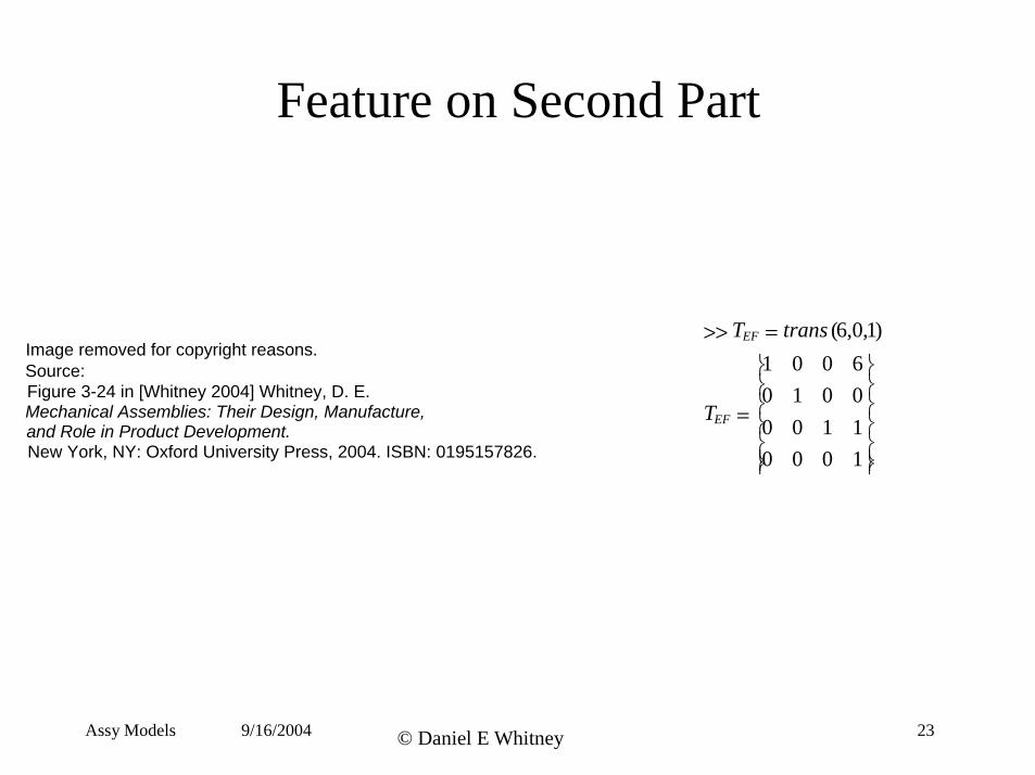
Feature on Second Part
>> TEF = trans (6,0,1)
1 0 0 6
0 1 0 0
TEF = 0 0 1 1
0 0 0 1
Assy Models 9/16/2004 © Daniel E Whitney 23
Image removed for copyright reasons.Source:Figure 3-24 in [Whitney 2004] Whitney, D. E. Mechanical Assemblies: Their Design, Manufacture, and Role in Product Development. New York, NY: Oxford University Press, 2004. ISBN: 0195157826.
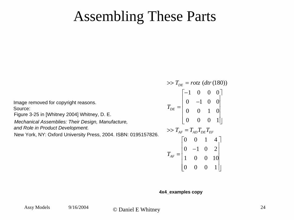
Assembling These Parts
>> TDE = rotz (dtr (180)) −1 0 0 0 0 −1 0 0
=TDE
Image removed for copyright reasons. Source: 0 0 1 0
0 0 0 1Figure 3-25 in [Whitney 2004] Whitney, D. E. Mechanical Assemblies: Their Design, Manufacture,
>> TAF = TADTDETEF and Role in Product Development.
0 0 0 −1 0 2
1 4New York, NY: Oxford University Press, 2004. ISBN: 0195157826.
=TAF 1 0 0 0
0 10 0 1
4x4_examples copy
Assy Models 9/16/2004 © Daniel E Whitney 24
Assy Models 25© Daniel E Whitney9/16/2004
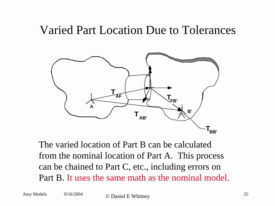
Varied Part Location Due to Tolerances
TT
T
AFFB'
AB'
AB'
TBB'
The varied location of Part B can be calculated from the nominal location of Part A. This processcan be chained to Part C, etc., including errors onPart B. It uses the same math as the nominal model.
Equations for Connective Models Nominal
Image removed for copyright reasons.Source:Figure 3-19 in [Whitney 2004] Whitney, D. E. Mechanical Assemblies: Their Design, Manufacture,
and Role in Product Development. New York, NY: Oxford University Press, 2004. ISBN: 0195157826.
Varied
Image removed for copyright reasons.Source:Figure 3-20 in [Whitney 2004] Whitney, D. E. Mechanical Assemblies: Their Design, Manufacture,
and Role in Product Development. New York, NY: Oxford University Press, 2004. ISBN: 0195157826.
Assy Models 9/16/2004 © Daniel E Whitney 26
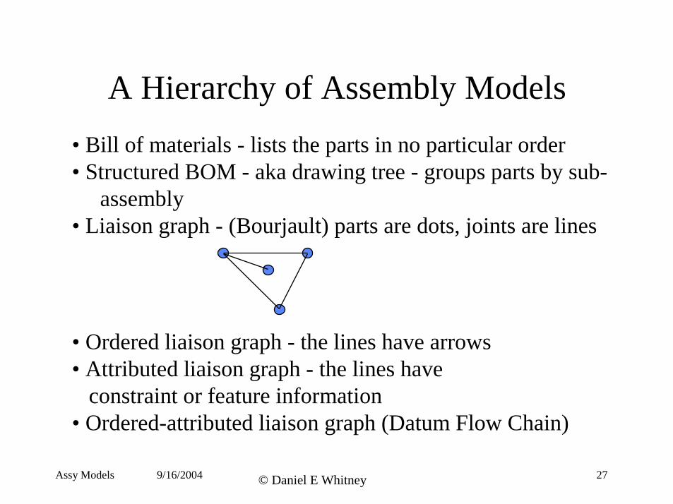
A Hierarchy of Assembly Models
• Bill of materials - lists the parts in no particular order• Structured BOM - aka drawing tree - groups parts by sub
assembly • Liaison graph - (Bourjault) parts are dots, joints are lines
• Ordered liaison graph - the lines have arrows • Attributed liaison graph - the lines have
constraint or feature information • Ordered-attributed liaison graph (Datum Flow Chain)
Assy Models 9/16/2004 © Daniel E Whitney 27
Assembly Types Classified Technically
Images removed for copyright reasons.Source:Figure 3-1 in [Whitney 2004] Whitney, D. E. Mechanical Assemblies: Their Design, Manufacture,
and Role in Product Development. New York, NY: Oxford University Press, 2004. ISBN: 0195157826.
Assy Models 9/16/2004 © Daniel E Whitney 28
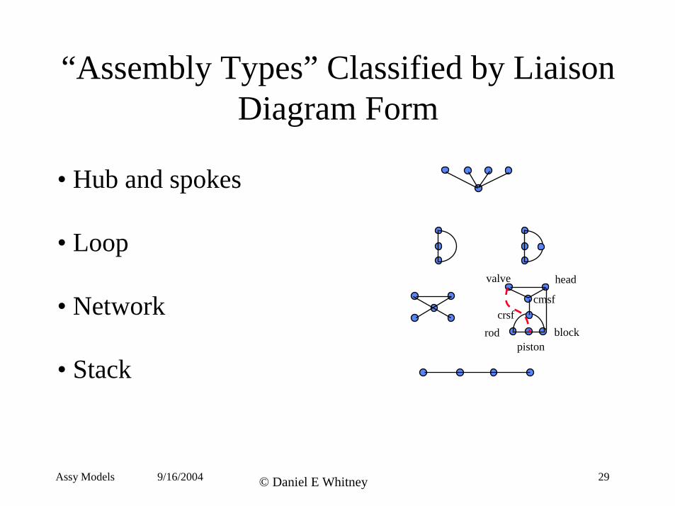
“Assembly Types” Classified by Liaison Diagram Form
• Hub and spokes
• Loop valve head
• Network crsf cmsf
block piston
rod
• Stack
Assy Models 9/16/2004 © Daniel E Whitney 29
Inside a Car Engine
Images removed for copyright reasons.Source:Figure 5-2 in [Whitney 2004] Whitney, D. E. Mechanical Assemblies: Their Design, Manufacture,
and Role in Product Development. New York, NY: Oxford University Press, 2004. ISBN: 0195157826.
Assy Models 9/16/2004 © Daniel E Whitney 30
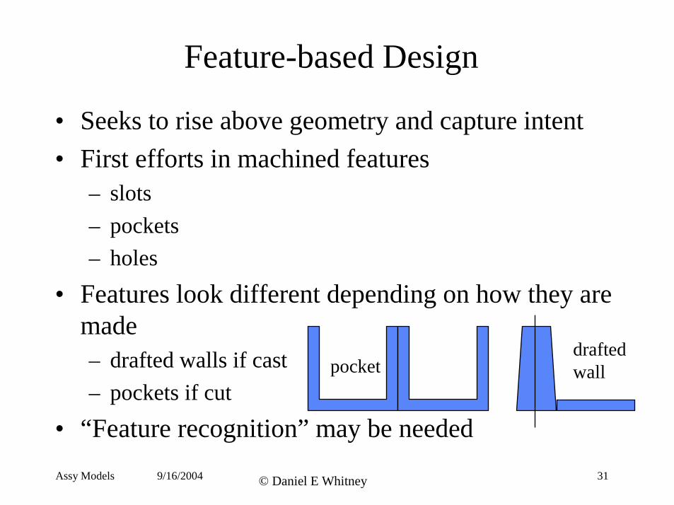
Feature-based Design
• Seeks to rise above geometry and capture intent • First efforts in machined features
– slots – pockets – holes
• Features look different depending on how they are made
drafted – drafted walls if cast pocket wall – pockets if cut
• “Feature recognition” may be needed Assy Models 9/16/2004 © Daniel E Whitney 31
Assembly Features Each feature has nominal geometry and a reference coordinate frame expressed as a 4x4 matrix. It also has a variety of other attributes as needed for its type.
Images removed for copyright reasons. “Feature recognition”
Source:Figure 3-12 in [Whitney 2004] Whitney, D. E. Mechanical Assemblies: Their Design, Manufacture,
may not be needed.and Role in Product Development.
.
New York, NY: Oxford University Press, 2004. ISBN: 0195157826. Story: Feature recognition of Philips
Head screws
Assy Models 9/16/2004 © Daniel E Whitney 32
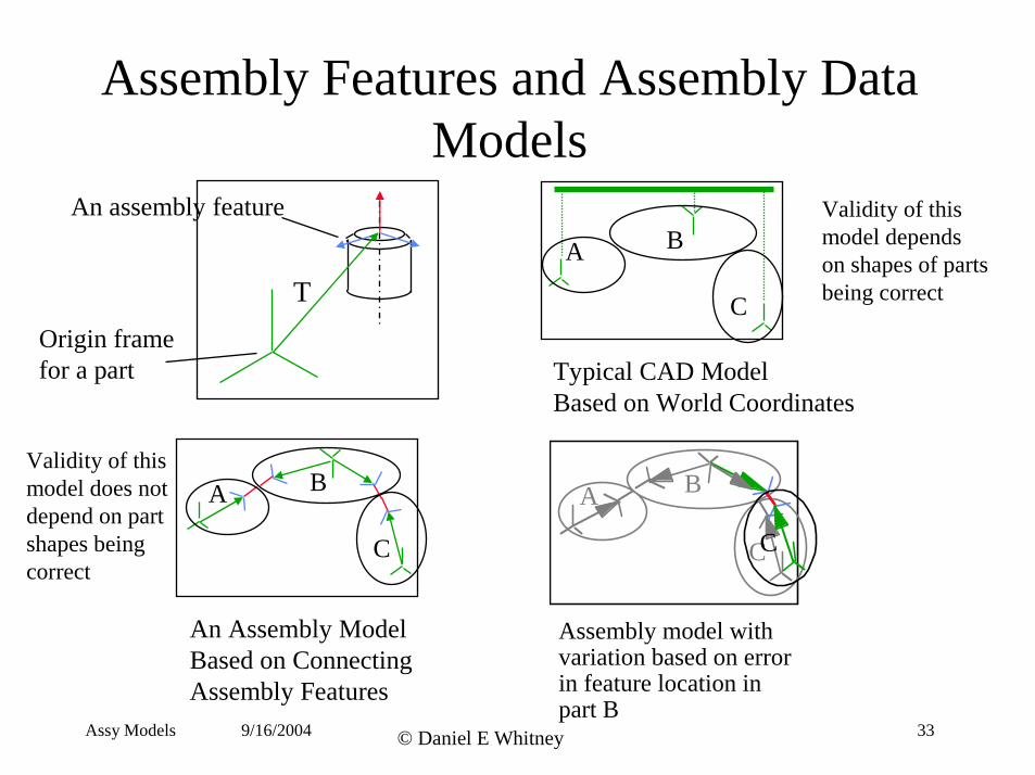
Assembly Features and Assembly Data Models
A B
C
A B
C
C
A B
C
T
shapes being
Typical CAD Model Based on World Coordinates
An assembly feature
Origin frame for a part
Validity of this model depends on shapes of parts being correct
Validity of this model does not depend on part
correct
An Assembly Model Assembly model with Based on Connecting variation based on error Assembly Features in feature location in
part BAssy Models 9/16/2004 © Daniel E Whitney 33
A Really Bad Example
Image removed for copyright reasons.Source:Figure 3-43 in [Whitney 2004] Whitney, D. E. Mechanical Assemblies: Their Design, Manufacture,
and Role in Product Development. New York, NY: Oxford University Press, 2004. ISBN: 0195157826.
Assy Models 9/16/2004 © Daniel E Whitney 34
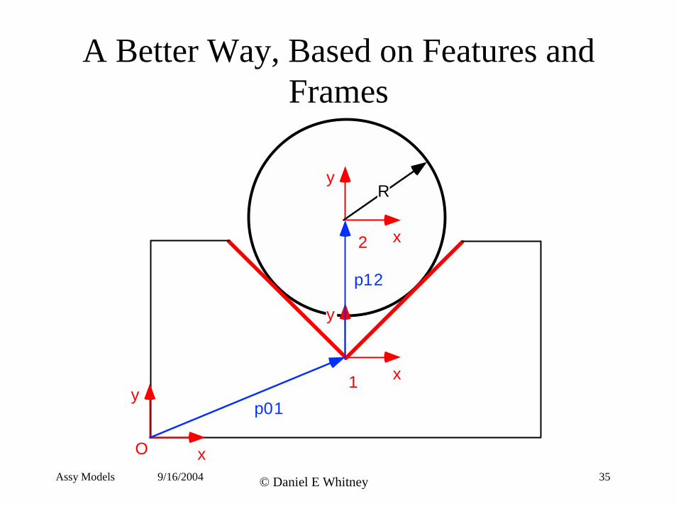
A Better Way, Based on Features and Frames
O x
y x
y
x
y
1
2
R
p01
p12
Assy Models 9/16/2004 © Daniel E Whitney 35
What The Different Models Do
• World coordinate model is good for drawing pictures of the nominal arrangement; can find interferences based on errors in the nominal but can’t help you find out why they happened
• Chained model is good for capturing relational information and design intent, and can trace effects of variation from the nominal; won’t necessarily find interferences because it forces things to be “assembled”; can help you find out why things don’t fit
Assy Models 9/16/2004 © Daniel E Whitney 36
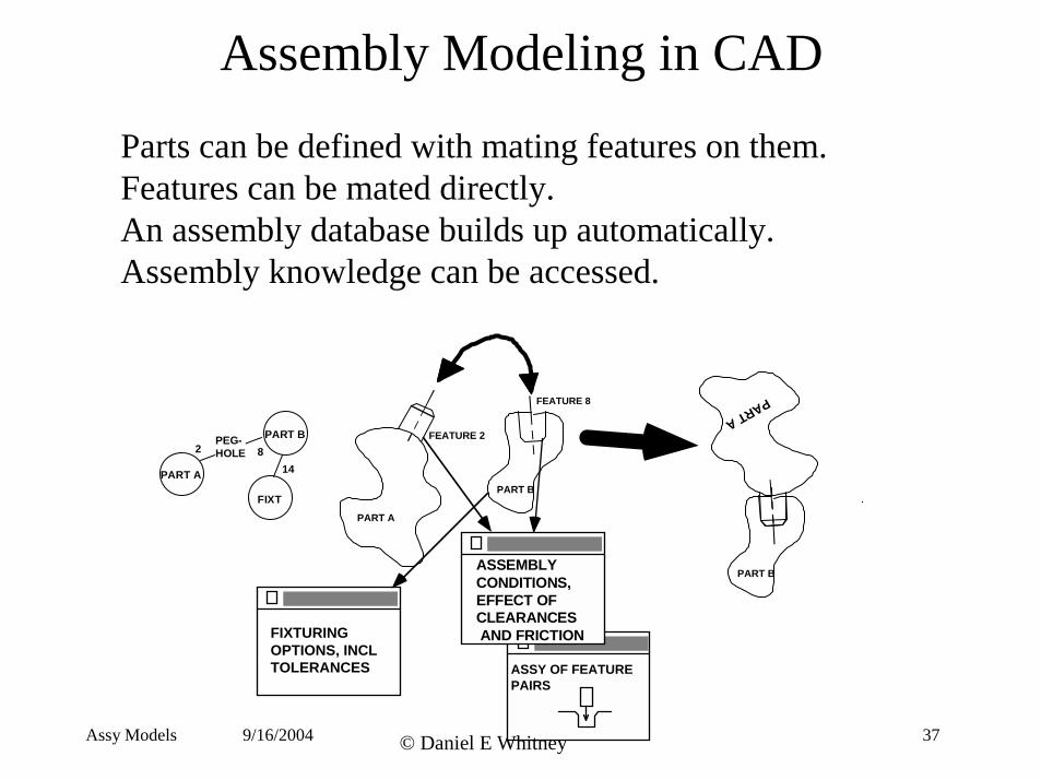
Assembly Modeling in CAD
Parts can be defined with mating features on them.Features can be mated directly.An assembly database builds up automatically.Assembly knowledge can be accessed.
9/16/2004
PART A
FEATURE 2
PART B
FEATURE 8
FIXTURING OPTIONS, INCL TOLERANCES
2 8 14
ASSY OF FEATURE PAIRS
PART B
PARTA
Assy Models © Daniel E Whitney
PART A
PART B PEGHOLE
FIXT
ASSEMBLY CONDITIONS, EFFECT OF CLEARANCES AND FRICTION
37
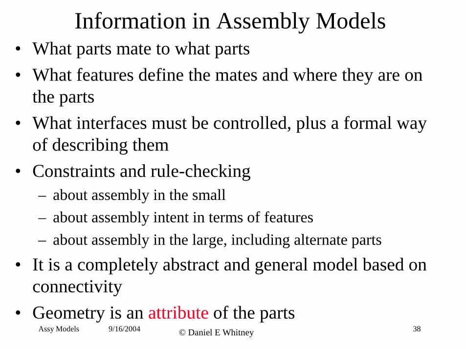
Information in Assembly Models• What parts mate to what parts
• What features define the mates and where they are on the parts
• What interfaces must be controlled, plus a formal way of describing them
• Constraints and rule-checking – about assembly in the small – about assembly intent in terms of features – about assembly in the large, including alternate parts
• It is a completely abstract and general model based on connectivity
• Geometry is an attribute of the partsAssy Models 9/16/2004 © Daniel E Whitney 38
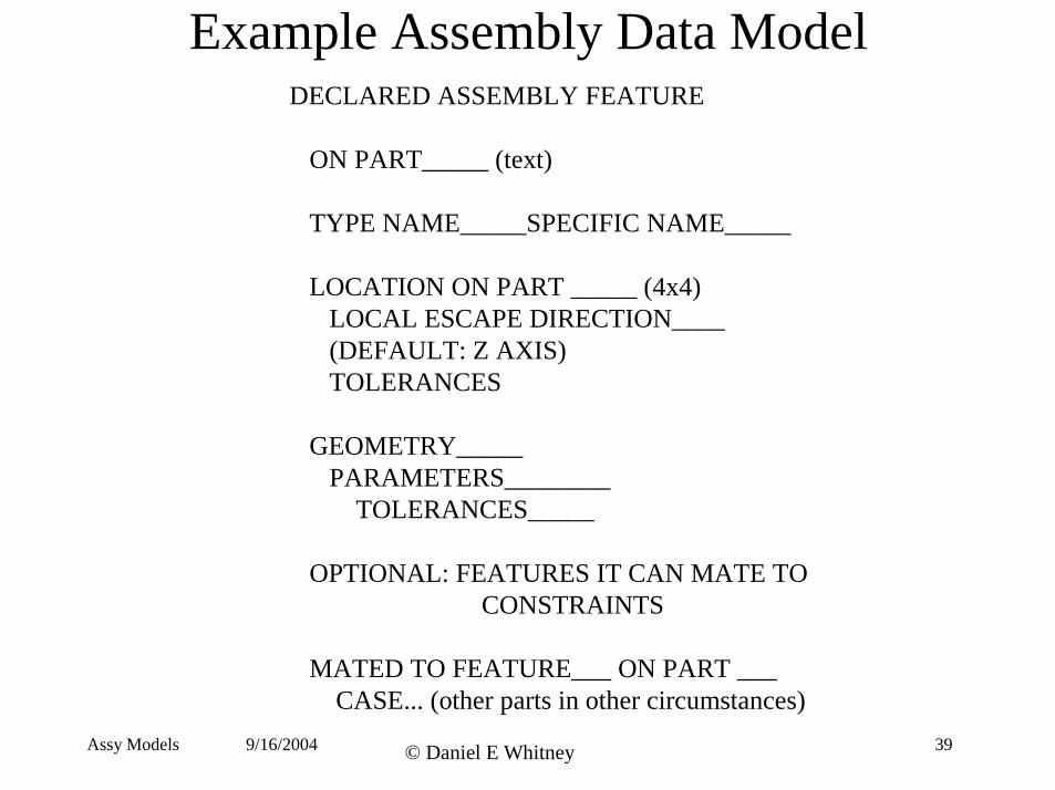
Example Assembly Data ModelDECLARED ASSEMBLY FEATURE
ON PART_____ (text)
TYPE NAME_____SPECIFIC NAME_____
LOCATION ON PART _____ (4x4)LOCAL ESCAPE DIRECTION____(DEFAULT: Z AXIS)TOLERANCES
GEOMETRY_____PARAMETERS________
TOLERANCES_____
OPTIONAL: FEATURES IT CAN MATE TO CONSTRAINTS
MATED TO FEATURE___ ON PART ___ CASE... (other parts in other circumstances)
Assy Models 9/16/2004 © Daniel E Whitney 39
Seeker Head
Image removed for copyright reasons.Source:Figure 3-28 in [Whitney 2004] Whitney, D. E. Mechanical Assemblies: Their Design, Manufacture,
and Role in Product Development. New York, NY: Oxford University Press, 2004. ISBN: 0195157826.
Assy Models 9/16/2004 © Daniel E Whitney 40
Seeker Liaison Diagram
Image removed for copyright reasons.Source:Figure 3-29 in [Whitney 2004] Whitney, D. E. Mechanical Assemblies: Their Design, Manufacture,
and Role in Product Development. New York, NY: Oxford University Press, 2004. ISBN: 0195157826.
Assy Models 9/16/2004 © Daniel E Whitney 41
Assy Models 42© Daniel E Whitney9/16/2004
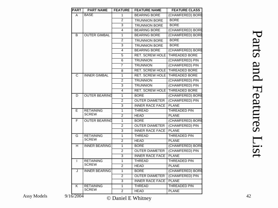
Parts and Features ListPART PART NAME FEATURE FEATURE NAME FEATURE CLASS
A 12
123456
C 1234
D 123
E 12
F 123
G 12
H 123
I 12
J 12312
K
B OUTER GIMBAL
BASE
INNER GIMBAL
OUTER BEARING
RETAININGSCREW
OUTER BEARING
RETAININGSCREW
INNER BEARING
RETAININGSCREW
RETAININGSCREW
INNER BEARING
BEARING BORE
BEARING BOREBEARING BORE
BEARING BORERET. SCREW HOLETRUNNION
BOREOUTER DIAMETERINNER RACE FACETHREADHEADBORE
THREADHEADBORE
THREADHEADBORE
THREADHEAD
RET. SCREW HOLERET. SCREW HOLE
RET. SCREW HOLE
OUTER DIAMETERINNER RACE FACE
OUTER DIAMETERINNER RACE FACE
OUTER DIAMETERINNER RACE FACE
(CHAMFERED) BORE
(CHAMFERED) BORE(CHAMFERED) BORE
(CHAMFERED) BORE
(CHAMFERED) PIN(CHAMFERED) PIN
(CHAMFERED) PIN(CHAMFERED) PIN
THREADED BORE
THREADED BORETHREADED BORE
THREADED BORE(CHAMFERED) BORE
(CHAMFERED) BORE
(CHAMFERED) BORE
(CHAMFERED) BORE
(CHAMFERED) PIN
(CHAMFERED) PIN
(CHAMFERED) PIN
(CHAMFERED) PIN
PLANETHREADED PINPLANE
PLANETHREADED PINPLANE
PLANETHREADED PINPLANE
PLANETHREADED PINPLANE
TRUNNION
TRUNNIONTRUNNION
34
TRUNNION BORETRUNNION BORE
BOREBORE
78
TRUNNION BORETRUNNION BORE
BOREBORE
Image removed for copyright reasons.Source:Figure 3-30 in [Whitney 2004] Whitney, D. E. Mechanical Assemblies: Their Design, Manufacture,
and Role in Product Development. New York, NY: Oxford University Press, 2004. ISBN: 0195157826.
Liaison Diagram
with
Features
Assy Models 9/16/2004 © Daniel E Whitney 43
Feature-based Design Video
• Made at Draper in 1990 • Illustrates a bottom-up approach
• First demo of integrated design of assembly tools hooked to a CAD system – parts designed with mating features – parts joined by connecting the features – liaison diagram constructed automatically
– assembly data model passed to CAE routines for assembly sequence, assembly system design, and economic analysis
Assy Models 9/16/2004 © Daniel E Whitney 44