Embed Size (px)
Citation preview
NETAJI SUBHAS INSTITUTE OF TECHNOLOGY
EC-316 Microprocessor Lab Project
MATH WIZARD
PROJECT BY:
SACHIN SINGH - 145/EC/13
SIDDHARTH YADAV - 171/EC/13
SYNOPSIS
This is an effort to build a single-player game titled “MATH WIZARD”
using microprocessor 8085. The game consists of a 16*2 LCD device
which is used to display to the user various mathematical equations that
needs to be answered by the user/player. The player has to make use of a
4*3 keypad matrix to press his/her final answer; this answer will be
displayed on the LCD after the button is pressed. After a button is pressed
and answer is displayed on the LCD screen, the buzzer goes off for a few
seconds indicating the user that the answer is correct. The final score will
be displayed on the LCD.
ACKNOWLEDGEMENT
Firstly we would like to thank Prof. Dhananjay Gadre for his unconditional
support and thorough guidance without which this project would not
have seen the light of the day. He not only guided us through the project
but also played a vital role in helping us relate the theoretical concepts
with their practical concepts and instilled in us enthusiasm to LEARN BY
DOING. This project was definitely a milestone in our career and we
learnt a lot more than just electronics, values of hard work and team
work.
We would also like to thank our friends and classmates especially Vikhyat,
Rohan anand and Rahul Vashist who worked with us and helped at each
and every point of time we needed help and assistance. From helping us
learn EAGLE, guiding to get PCB ready, helping us through the soldering
sessions, getting corrections in software and also final checks on the
game (they enjoyed playing the game as well) and what not, they were
always with us. It was a really good memorable experience working with
all of them.
We would also like to thank all the staff of the Department of Electronics
of Netaji Subhas Institute of Technology for providing us with all the
requisites for completion of this project.
TABLE OF CONTENTS :
1. INTRODUCTION
2. PROJECT DESCRIPTION
i) Block Diagram
ii) Components Required
3. SCHEMATIC FILE
4. GANTT CHART REVISITED
5. PICTURES FROM THE PROJECT
6. TESTING AND VALIDATION
7. CONCLUSION
8. BIBLIOGRAPHY
INTRODUCTION :
Intel 8085 was an important milestone in the development of
microprocessors. It required less circuitry as compared to its
contemporary counterparts. As a result, it was possible to build simpler
and cheaper micro-computer systems. Intel 8085 is an ideal
microprocessor for the purpose of introducing students with the vast
subject of microprocessors.
Since we are required to develop a project based on Intel 8085, we
decided to make use of its input-output, interrupt and computational
abilities. We were inspired to make a project whereby we can use all the
above mentioned features of Intel 8085 and use it to create a project
which is fun and enjoyable.
This project was designed for testing speeds of various individuals in
solving mathematical equations as fast as they can. This project can be
extended to various other applications such as testing the IQ of an
individual by displaying various varieties of questions on the 16*2 LCD.
Also the limit of this project can be used in testing the speeds of 2 players
against each other or with respect to time as well.

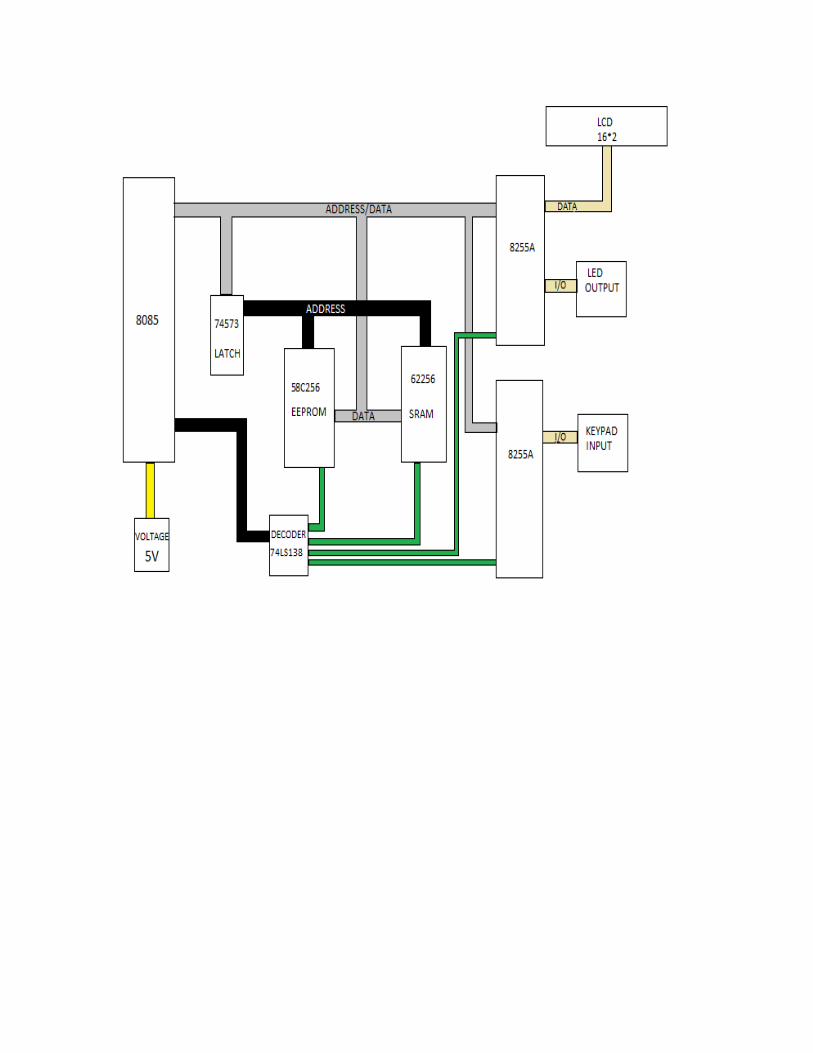
PROJECT DESCRIPTION i) Block Diagram :-
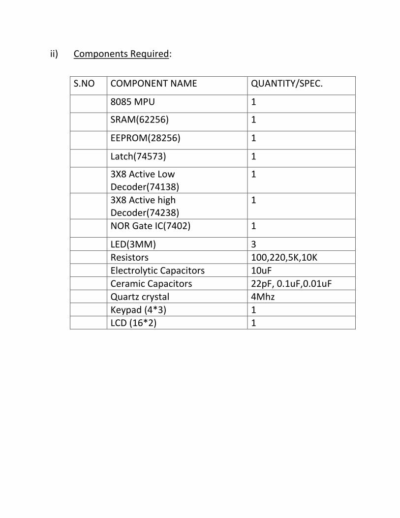
ii) Components Required:
S.NO COMPONENT NAME QUANTITY/SPEC.
8085 MPU 1
SRAM(62256) 1
EEPROM(28256) 1
Latch(74573) 1
3X8 Active Low Decoder(74138)
1
3X8 Active high Decoder(74238)
1
NOR Gate IC(7402) 1
LED(3MM) 3
Resistors 100,220,5K,10K
Electrolytic Capacitors 10uF
Ceramic Capacitors 22pF, 0.1uF,0.01uF
Quartz crystal 4Mhz
Keypad (4*3) 1 LCD (16*2) 1
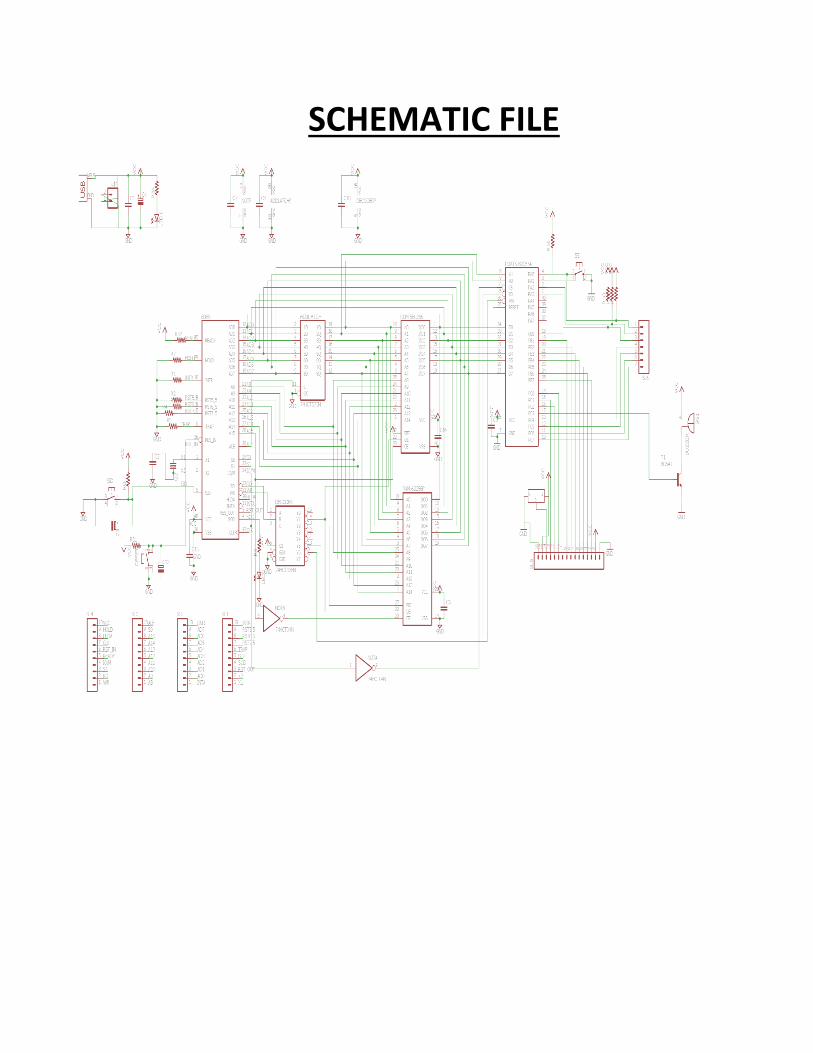
SCHEMATIC FILE
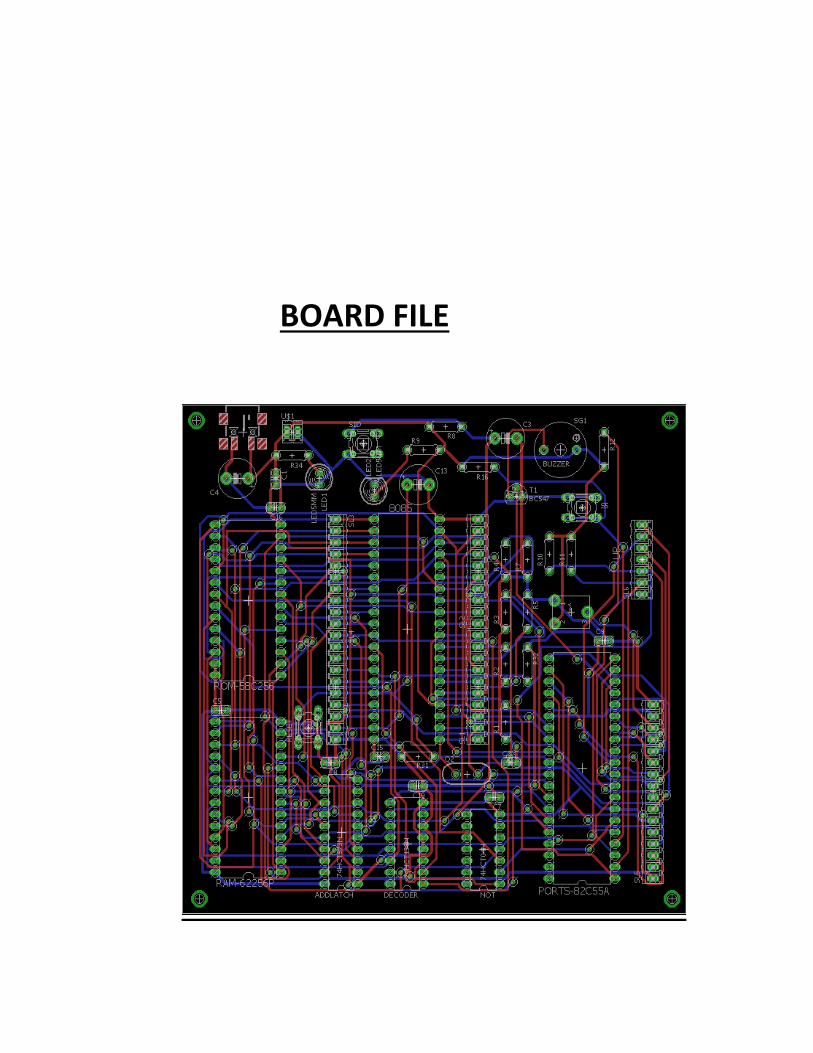
BOARD FILE
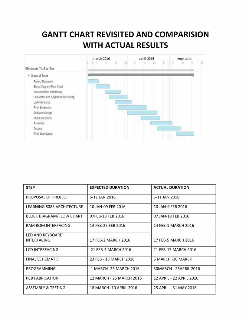
GANTT CHART REVISITED AND COMPARISION WITH ACTUAL RESULTS
STEP EXPECTED DURATION ACTUAL DURATION
PROPOSAL OF PROJECT 5-11 JAN 2016 5-11 JAN 2016
LEARNING 8085 ARCHITECTURE 10 JAN-09 FEB 2016 10 JAN-9 FEB 2016
BLOCK DIAGRAM/FLOW CHART 07FEB-18 FEB 2016 07 JAN-18 FEB 2016
RAM ROM INTERFACING 14 FEB-25 FEB 2016 14 FEB-1 MARCH 2016
LED AND KEYBOARD INTERFACING 17 FEB-2 MARCH 2016 17 FEB-5 MARCH 2016
LCD INTERFACING 21 FEB-4 MARCH 2016 21 FEB-15 MARCH 2016
FINAL SCHEMATIC 23 FEB - 15 MARCH 2016 5 MARCH -30 MARCH
PROGRAMMING 1 MARCH -25 MARCH 2016 30MARCH - 25APRIL 2016
PCB FABRICATION 12 MARCH - 25 MARCH 2016 12 APRIL - 22 APRIL 2016
ASSEMBLY & TESTING 18 MARCH- 10 APRIL 2016 25 APRIL - 31 MAY 2016
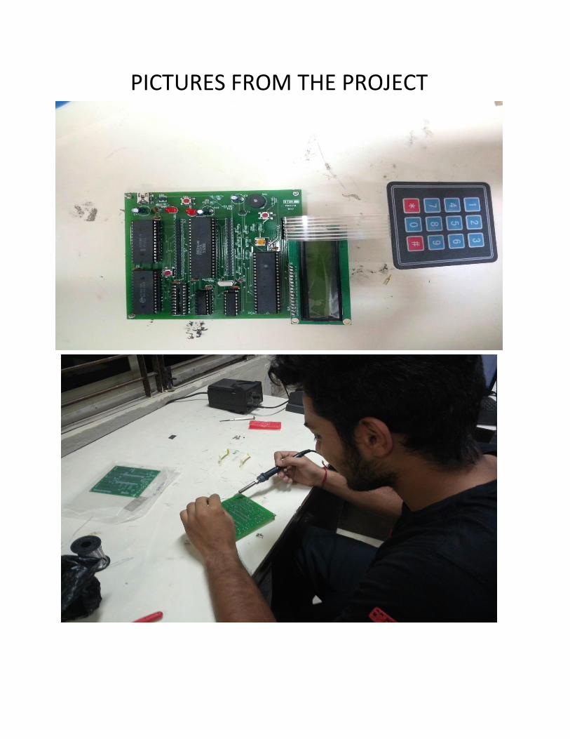
PICTURES FROM THE PROJECT
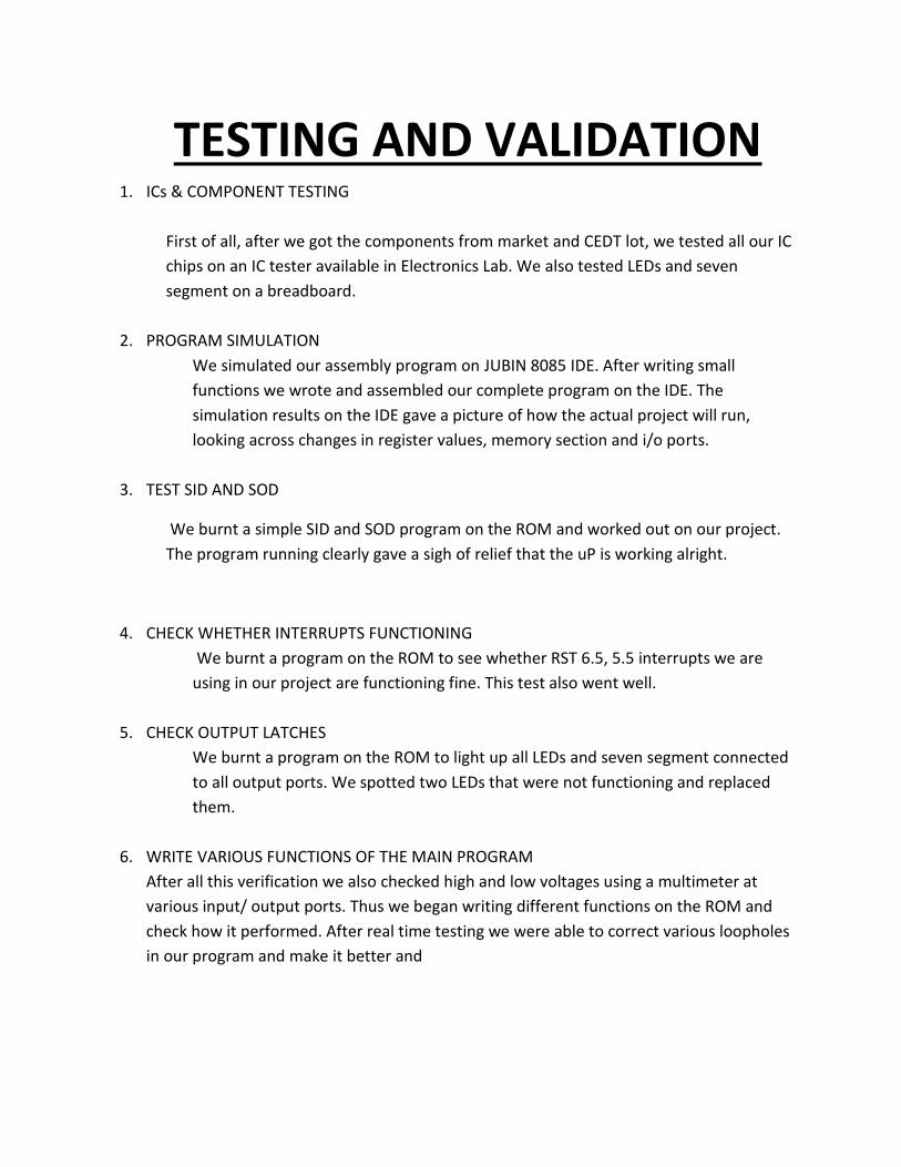
TESTING AND VALIDATION 1. ICs & COMPONENT TESTING
First of all, after we got the components from market and CEDT lot, we tested all our IC
chips on an IC tester available in Electronics Lab. We also tested LEDs and seven
segment on a breadboard.
2. PROGRAM SIMULATION
We simulated our assembly program on JUBIN 8085 IDE. After writing small
functions we wrote and assembled our complete program on the IDE. The
simulation results on the IDE gave a picture of how the actual project will run,
looking across changes in register values, memory section and i/o ports.
3. TEST SID AND SOD
We burnt a simple SID and SOD program on the ROM and worked out on our project.
The program running clearly gave a sigh of relief that the uP is working alright.
4. CHECK WHETHER INTERRUPTS FUNCTIONING
We burnt a program on the ROM to see whether RST 6.5, 5.5 interrupts we are
using in our project are functioning fine. This test also went well.
5. CHECK OUTPUT LATCHES
We burnt a program on the ROM to light up all LEDs and seven segment connected
to all output ports. We spotted two LEDs that were not functioning and replaced
them.
6. WRITE VARIOUS FUNCTIONS OF THE MAIN PROGRAM
After all this verification we also checked high and low voltages using a multimeter at
various input/ output ports. Thus we began writing different functions on the ROM and
check how it performed. After real time testing we were able to correct various loopholes
in our program and make it better and
CONCLUSION
EC-316 MICROPROCESSORS PROJECT has been a thoroughly enriching
experience. We thank Prof. Gadre for such an opportunity which made us
learn in depth about microprocessors and assembly language
programming as well as small electronics things which are generally
bypassed by the big concepts like led voltages, role of resistors, capacitors
etc. It gave a good experience in digital as well as analog electronics.
Learning by doing was accomplished.
Coming to the project we worked on, we designed a 8085 based project
capable of displaying mathematical equations on the 16*2 LCD and taking
the input from the user using a 4*3 keypad matrix displaying the final
result and buzzer goes on as soon as the answer is displayed.
BIBLIOGRAPHY
TEXTBOOKS:
1. Microprocessor Architecture, Programming, and Applications with the
8085 Author: Ramesh Gaonkar Publisher: Penram International
Publishing (India) Pvt. Ltd Edition: 5th edition ISBN: 9788187972099
2. The 8085 Microprocessor: Architecture, Programming and Interfacing
Author: K.Udaya Kumar, B.S.Umashankar Publisher: Pearson Education
India Edition: 1st edition ISBN: 9788177584554
3. Microprocessors and Interfacing Author: Douglas V. Hall Publisher:
Mcgraw Hill Education Edition: 3rd edition ISBN: 9781259006159
DATASHEETS PROVIDED BY PROF. GADRE
https://drive.google.com/folderview?id=0ByFqcybodzN8LS1PRTliN1lSdUU
&usp=sharing
WEB LINKS
1. https://en.wikipedia.org/wiki/Intel_8085 2.
www.nptel.ac.in/courses/106108100/pdf/Teacher_Slides/mod1/M1L2.pdf
3.http://electronicsproject.org/microprocessor-based-home-security-
system/ 4.http://8085projects.info/page/8085-microprocessor-based-
projects.html 5.http://www.circuitstoday.com/lab-
manuals/microprocessor-lab 6.https://learn.sparkfun.com/tutorials/pull-
up-resistors 7.http://www.labbookpages.co.uk/electronics/debounce.html
8.http://www.all-electric.com/schematic/debounce.html.