Embed Size (px)
Citation preview

Mathematically Modeling the Mechanics of Cell Division
Shuyuan Wang
Submitted in partial fulfillment of the requirements for the degree of
Doctor of Philosophy of the Graduate School of Arts and Sciences
COLUMBIA UNIVERSITY
2018

© 2017
Shuyuan Wang
All rights reserved

ABSTRACT
Mathematically Modeling the Mechanics of Cell Division
Shuyuan Wang
The final stage of the cell cycle is cell division by cytokinesis, when the cell physically separates into two
daughter cells. Improper timing or location of the division site results in incorrect segregation of
chromosomes and thus genetically unstable aneuploid cells, which is associated with tumorigenesis.
Cytokinesis in animal, fungal and amoeboid cells occurs through the assembly and constriction of an
actomyosin contractile ring, a mechanism that dates back about one billion years in the common ancestor
of these organisms. However, it is not well understood how the ring generates tension or how the rate of
ring constriction is set. Long ago a sliding filament mechanism similar to skeletal muscle was proposed,
but definitive evidence for muscle-like sarcomeric order in the ring is lacking.
Here we build mathematical models of cytokinesis in the fission yeast Schizosaccharomyces pombe,
where the most complete inventory of more than 150 cytokinesis genes have been documented. The
models explicitly represent proteins in the contractile ring such as formin, myosin, actin, α-actinin, etc. and
implements their quantities, biomechanical properties and organizations from the best available
experimental information. At the same time, the models adopt coarse-grain approaches that are able to
describe the collective behaviors of thousands of ring components, which include tension production,
constriction, and disassembly of the ring.
In the first part of this thesis, we modeled the extraordinarily rapid constriction of the partially unanchored
ring in fission yeast cell ghosts. Experiments on isolated fission yeast rings showed sections of ring
unanchoring from the membrane and shortening ~30-fold faster than normal (1). We demonstrated that
anchoring of actin to the plasma membrane generates tension in the fission yeast cytokinetic ring by
showing (1) unanchored segments in these experiments were tensionless, and (2) only a barbed-end
anchoring of actin can generate tension in the normally anchored ring, and can explain the extraordinary
behavior of unanchored segments. Molecularly explicit simulations accurately reproduced experimental

constriction rates, and showed a novel non-contractile reeling-in mechanism by which the unanchored
segment shortens, despite being tensionless.
In the second part of this thesis, we built a highly coarse-grained model to study how ring tension is
generated and how structural stability is maintained. Recently, a super-resolution microscopy study of the
fission yeast ring revealed that myosins and formins that nucleate actin filaments colocalize in plasma
membrane-anchored complexes called nodes in the constricting ring (2). The nodes move bidirectionally
around the ring. Here we construct and analyze a coarse-grained mathematical model of the fission yeast
ring to explore essential consequences of the recently discovered ring ultrastructure. The model
reproduces experimentally measured values of ring tension, explains why nodes move bidirectionally and
shows that tension is generated by myosin pulling on barbed-end-anchored actin filaments in a stochastic
sliding-filament mechanism. This mechanism is not based on an ordered sarcomeric organization. We
show that the ring is vulnerable to intrinsic contractile instabilities, and protection from these instabilities
and organizational homeostasis require both component turnover and anchoring of components to the
plasma membrane.
In the third part of this thesis, we measured ring tension in fission yeast protoplasts. We found ~650 pN
tension in wild type cells, ~65% the normal tension in myp2 deletion mutants and ~40% normal tension in
myo2-E1 mutant cells with negligible ATPase activity and reduced actin binding. To understand the
relation between organization and tension, we developed a molecularly explicit simulation of the fission
yeast ring with the above organization. Our simulations revealed a clear division of labor between the 2
myosin-II isoforms, which maintains organization and maximal tension. (1) Myo2 anchors the ring to the
plasma membrane, and transmits ring tension to the membrane. (2) Myo2, extending ~100 nm away from
the membrane, bundles half (~25) of the actin filaments in the cross-section due to filament packing
constraints, as only ~25 filaments are within reach. (3) To increase tension requires that the ring be
thickened, as tensions in the ~25 membrane-proximal filaments are close to fracture. (4) Unanchored
Myp2 indeed enables thickening, by bundling an additional ~25 filaments and doubling tension. Anchoring
of these filaments to the membrane is indirect, via filaments shared with the anchored Myo2. (5) In
simulated myo2-E1 rings ~20% of the actin filaments peeled away from the ring and formed Myp2-

dressed bridges, as observed experimentally in myo2-E1 cells. (6) The organization in simulated Δmyp2
rings was highly disrupted, with ~ 50% of the actin filaments unbundled. Therefore, beyond their widely
recognized job to pull actin and generate tension, myosin-II isoforms are vital crosslinking organizational
elements of the ring. Two isoforms in the ring cooperate to organize the ring for maximal actomyosin
interaction and tension.

i
Table of Contents
List of charts, graphs, illustrations ............................................................................................................... iii
I. Introduction .......................................................................................................................................... 1
i. The importance of cell division, cytokinesis and the contractile ring............................................... 1
ii. The cytokinetic contractile ring is a cellular machine that remains poorly understood .................. 1
iii. The special status of fission yeast in cytokinesis research ............................................................... 2
iv. Studying the ring in isolation: fission yeast protoplasts and cell ghosts .......................................... 2
v. Outline............................................................................................................................................... 2
II. Anchoring of actin to the plasma membrane generates tension in the fission yeast cytokinetic ring 4
i. Introduction ...................................................................................................................................... 4
ii. Results ............................................................................................................................................... 6
iii. Discussion ........................................................................................................................................ 21
iv. Appendix A1. 3D molecularly explicit model of the cytokinetic ring in permeabilized fission yeast
protoplasts .............................................................................................................................................. 24
v. Appendix A2. Simulation of the model: constriction of partially unanchored rings ...................... 38
vi. Appendix A3. Determination of model parameters ....................................................................... 43
vii. Appendix A4. The reeling-in constriction mechanism ................................................................ 47
viii. Appendix A5. Fitting the model-predicted ATP-dependence of the myosin-II load-free velocity
to Michaelis-Menten kinetics ................................................................................................................. 49
III. A node organization in the actomyosin contractile ring generates tension and aids stability....... 51
i. Introduction .................................................................................................................................... 51
ii. Results ............................................................................................................................................. 52
iii. Discussion ........................................................................................................................................ 74
iv. Appendix A: Derivation and numerical solution of the model equations ...................................... 78
IV. The two myosin-II isoforms in the fission yeast contractile ring complement one another to
generate tension and endow structural integrity to the ring ..................................................................... 84
i. Introduction .................................................................................................................................... 84
ii. Results ............................................................................................................................................. 86
iii. Discussion ...................................................................................................................................... 113
V. Conclusions ....................................................................................................................................... 123
i. The cytokinetic ring tension requires anchoring of actin filament barbed-ends ......................... 123
ii. A stochastic sliding filament mechanism involving two classes of nodes generates tension ...... 124

ii
iii. Two myosin-II isoforms complement each other to generate tension and endow structural
integrity to the ring ............................................................................................................................... 125
iv. Component turnover and anchoring protects the ring from intrinsic contractile instabilities .... 125
References ................................................................................................................................................ 126

iii
List of charts, graphs, illustrations
Figure 2.1. Schematic of cytokinetic ring constriction observed in permeabilized fission yeast protoplasts
by Mishra et al. (1). ....................................................................................................................................... 6
Figure 2.2. Barbed end anchored 3D model of the cytokinetic ring in permeabilized fission yeast
protoplasts (components not to scale). ........................................................................................................ 8
Figure 2.3. Unanchored ring segments have zero tension and constrict at close to the load-free velocity
of mysoin-II, 𝑣myo0, independently of initial length. ................................................................................ 11
Figure 2.4. Unanchored ring segments are non-contractile and shorten by being reeled in at close to the
myosin-II load-free velocity, 𝑣myo0 = 0.24 μm s − 1. ............................................................................. 14
Figure 2.5. Reeling in mechanism of ring constriction in permeabilized protoplasts. ............................... 17
Figure 2.6. Constriction of cytokinetic rings in permeabilized protoplasts requires anchoring of actin but
not actin turnover. ...................................................................................................................................... 20
Figure 2.7. Myosin-II load free velocity and constriction rate versus ATP concentration. ......................... 21
Figure 2.9 α-actinin crosslinking has no effect on the ring constriction rate. ............................................ 30
Figure 2.10 The simulated ring tension and constriction rate are unaffected by the value of the viscosity
of the aqueous medium used in the simulation. ........................................................................................ 35
Table 2.1. Model Parameters ...................................................................................................................... 43
Figure 3.1: Mathematical model of the constricting fission yeast cytokinetic ring. ................................... 55
Table 3.1. Parameters of the mathematical model of the S. pombe cytokinetic ring ................................ 58
Figure 3.2: Actin and myosin in nodes contra-rotate around the steady state cytokinetic ring. ............... 61
Figure 3.3: The fission yeast ring generates tension by myosin pulling on barbed-end anchored actin
filaments. .................................................................................................................................................... 66
Figure 3.4: Turnover of actin and myosin in nodes prevents aggregation of nodes, loss of tension and
ring fracture. ............................................................................................................................................... 70
Figure 3.5: Weakening the lateral anchor drag leads to faster node aggregation and ring fracture in the
absence of turnover. ................................................................................................................................... 73
Figure 4.1. Method to measure cytokinetic ring tension in fission yeast protoplasts. .............................. 89
Figure 4.2. Cytokinetic ring tension increases as the ring constricts. ......................................................... 90
Figure 4.3. Ring tension depends on both myosin-II isoforms. .................................................................. 92
Figure 4.4. Mathematical model of the fission yeast cytokinetic ring with distinct myosin-II isoforms. ... 99
Figure 4.5. Ring tension is produced by Myo2 and Myp2 pulling on barbed-end-anchored actin filaments.
.................................................................................................................................................................. 105
Figure 4.6. Myo2 and Myp2 collaborate to generate tension and organize the ring. .............................. 107
Figure 4.7. Furrowed protoplasts are variable in size, have higher membrane tension, and recruit septum
synthesis machinery to cytokinetic rings. ................................................................................................. 110
Figure 4.8. Cells tensions increased at rates in the range ~0.1 to ~5% per min. ...................................... 111
Figure 4.9. Integrity of the ring requires sufficiently strong binding of myosin-II to actin. ...................... 112
Figure. 4.10. Tension in actin filaments increases approximately linearly as a function of the distance
from the pointed end. ............................................................................................................................... 113
Table 4.1. Key parameter values of the ring simulation. .......................................................................... 120
Table 4.2. List of S. pombe strains used in this study ............................................................................... 122

iv
Acknowledgments
I wish to thank my adviser, Ben O’Shaughnessy, for his unrelenting passion in discovering the truth of
biological systems that impassioned me and the whole group continuously. Without his expertise,
commitment and foresight, this work would have been impossible. I also with to thank Sathish Thiyagarajan,
my long term colleague, as well as Dr. Harvey F. Chin, Dr. Brett Alcott and Dr. Anirban Polley with whom I
was fortunate to collaborate in the O’Shaughnessy group.
I am also grateful to our collaborators Dr. Thomas Pollard and Dr. Caroline Laplante at Yale University, and
Dr. Mohan K. Balasubramanian at Warwick University. Their experiments were a source of inspiration to
my work, and also made my work much richer and more interesting.
Finally, I thank my wife Weiling Yu who has been a constant source of understanding, encouragement and
love from the beginning of this work to the end.

v
To my wife.

1
Chapter 1
I. Introduction
i. The importance of cell division, cytokinesis and the contractile ring
Cell division is a crucial aspect of life. The genome is replicated, and each copy is inherited by the two
daughter cells, thus ensuring genomic identity of all cells in a multicellular organism. Cell division is
crucial for growth and development of the embryo, for wound healing and for the continuous replacement
of old cells with new ones. Typically happening at the end of cell division, cytokinesis is the process that
the cell physically divides into two parts. It is essential for embryo development and maintenance of tissue
that the division of somatic stem cells be precisely placed and timed (3); misregulated cytokinesis is
implicated in tumorigenesis and multinucleate cells (4).
In animal, fungal and amoeboid cells, cytokinesis is driven or directed by an actomyosin contractile ring
(5-7), which is assembled at the division site, produces tension and constricts during cytokinesis. A
fundamental challenge in cell biology is to understand how the ring is organized, produces tension, and
constricts.
ii. The cytokinetic contractile ring is a cellular machine that remains poorly understood
Despite its vital role in the cell, how the cytokinetic contractile ring works is not well understood. It has
been proposed that actin filaments and myosin-II in the ring generate tension by a sliding filament
mechanism similar to that in striated muscle (8, 9), but unlike striated muscle, there is inconclusive
evidence supporting an ordered (sarcomeric) organization of the ring (5, 10-12). On the other hand, it is
unclear how tension can emerge from a randomly organized actomyosin bundle, as a symmetry
argument would suggest zero tension. Equally unclear is how the ring maintains an organization suitable
for tension generation, given that it constantly sheds material and incorporates new material as it
constricts. It is the aim of this thesis to address these questions.

2
iii. The special status of fission yeast in cytokinesis research
Fission yeast is a unique model organism well suited for quantitative modeling of the cytokinetic ring,
providing by far the most sufficient molecular detail for experimentally justified and biologically meaningful
mathematical modeling. With > 150 proteins identified, the fission yeast cytokinetic ring is arguably the
best characterized (13). Moreover, the amounts of > 25 ring components have been measured as
cytokinesis proceeds (7, 14, 15). Knowledge of the cytokinetic ring gained in fission yeast will be
applicable to many organisms as many ring proteins are conserved (13).
iv. Studying the ring in isolation: fission yeast protoplasts and cell ghosts
Enzymatic digestion of the fission yeast cell wall makes protoplasts. Unlike many other cells, fission yeast
lacks an actomyosin cortex, and thus contractile rings in fission yeast protoplasts are mechanically
connected to the plasma membrane only. Such mechanical isolation was exploited in an earlier work of
our group to measure the ring tension in a primitive way, with an unrealistic assumption that membrane
tension is equal in protoplasts with and without a ring (16). However, this work did observe spherical
shapes of the lobes flanking the ring, supporting the absence of an actomyosin cortex and that the rings
are mechanically isolated.
A further development of the fission yeast protoplast “laboratory” was achieved by permeabilizing the
plasma membrane, in recent works of the Balasubramanian and Mabuchi labs (1, 17). In these cell
ghosts, the cytoplasm is removed and binding of new components onto the ring is switched off; the
membrane is weakened, and entire ring segments break away from the membrane. Therefore, cell ghosts
provide a unique opportunity to test the effect of turnover and membrane anchoring.
v. Outline
Chapter 2 of this thesis establishes that the ring generates tension by anchoring components to the
plasma membrane, using fission yeast cell ghosts as the model system. In this system, a recent study

3
found that ring segments detach from the plasma membrane and shortened at a rate ~ 30 times faster
than normal (1). Here we developed a molecularly detailed simulation to model this situation, where the
motion of the ring required the simulation to allow length dynamics in 3D and to have realistic myosin
force-velocity relations. Our model demonstrated that the unanchored ring segments had negligible
tension and confirmed that ring tension depends on component anchoring. Moreover, our model revealed
a novel “reeling-in” constriction mode of the ring, where the anchored segment reels in the unanchored
one at the rate comparable to the myosin-II load-free velocity, an interfacial effect. This prediction is in
quantitative agreement with experimental observation (1).
In Chapter 3 of this thesis, we present a coarse-grained 1D analytical model incorporating the node-
based structure of fission yeast cytokinetic ring. We investigate whether tension can be generated from
such structure through a sarcomere-like mechanism, one that is distinct from the membrane-anchor-
based mechanism that we proposed in Chapter 2. In fact, we show that although the node-based
structure generates tension, tension is doubled by anchoring the nodes to the plasma membrane. We
then apply the model to demonstrate that anchoring protects the ring from intrinsic structural instabilities,
working together with component turnover.
In Chapter 4 we develop a molecularly explicit model of the ring, incorporating the latest experimental
findings: formin Cdc12 and myosin-II Myo2 colocalize in membrane-anchored nodes (2), while
unconventional myosin-II Myp2 clusters localize to the ring in an actin-dependent way and are
unanchored to the plasma membrane (11, 18, 19). Moreover, for the first time the time-evolution of ring
component amounts has been realistically included, whereas in the previous model versions ring
component amounts were kept constant. This allows us to predict the time-evolution of ring tension and to
compare with our own experimental measurements of ring tension. This model can be applied not only in
in wild-type but also in mutants, such as the deletion mutant Δmyp2 where Myp2 is absent in the ring, or
the temperature-sensitive mutant myo2-E1 where even in permissive temperature Myo2p-E1 has minimal
ATPase activity and reduced actin binding (20, 21). Accordingly, experimental measurements of ring
tension and ring structure in these mutants can be compared to model predictions.

4
Chapter 2
II. Anchoring of actin to the plasma membrane generates tension in the fission yeast
cytokinetic ring
In this chapter, we describe theoretical work that explains an interesting published experiment by the
Balasubramanian and Mabuchi groups (1), and reveals the mechanism by which the ring generates
tension.
i. Introduction
Cytokinesis is the final stage of the cell cycle, when an actomyosin ring is assembled and then constricts
the cell into two. The primary function of the ring is thought to be tension production that drives or
regulates cleavage of the cell. Ring tensions of 10 − 50 nN were reported in echinoderm embryos (22-25)
and ~ 400 pN in protoplasts of the fission yeast Schizosaccharomyces pombe (16), but the mechanism
that produces tension is not established.
How are actin, myosin, and other components organized in the ring, and how do they interact to generate
tension? The classic actomyosin contractile machine is the myofibril of striated muscle, with its highly
ordered architecture of sarcomere repeat units in series. Following the discovery of the contractile ring
and the presence of actin and myosin-II in the ring, a mechanism similar to that in striated muscle was
proposed, in which actin filaments are pulled by and slide relative to myosin-II (26-28). However,
cytokinetic rings appear to have relatively disordered organizations and definitive evidence for sarcomeric
order is lacking (11, 12). How ring tension could emerge from such irregularity is an open question.
A growing body of evidence suggests that ring tension is generated by anchoring of actin filaments to the
plasma membrane. Long ago EM images of contractile rings in HeLa cells revealed actin filaments that
converged on densities on the plasma membrane that might serve as anchors (9). More recently it was
demonstrated that, during assembly of the S. pombe ring, anchored myosin-II pulls actin filaments

5
anchored to the membrane by their barbed ends, producing tension in the filaments that draws precursors
of the ring together (29). The essential mechanism is simple: when myosin-II pulls a filament, anchors
provide the necessary lateral resistance for a filament to develop tension. In fully developed constricting
fission yeast rings, this tension-generating mechanism is supported by molecularly detailed simulations
that reproduce experimentally measured ring tensions (16), and a recent super-resolution microscopy
study showed that anchoring of formin Cdc12p and myosin-II to the plasma membrane persists into
constricting rings (2). Cdc12 dimers nucleate and grow actin filaments while processively capping their
barbed ends, suggesting that actin filament barbed ends in the ring are anchored to the membrane.
Provided the anchors have low lateral mobility in the membrane, actin filaments would develop tension
when pulled by myosin-II, consistent with the measured lateral node velocities (2).
If anchoring of actin is indeed responsible for tension, ring tension should be affected when anchoring is
compromised. The effect of anchor loss was examined in an experimental study of fission yeast cell
ghosts, permeabilized cells that lack cytoplasm and provide a unique laboratory to study isolated
cytokinetic rings (1). On addition of ATP, entire sections of rings became unanchored by pulling away
from the plasma membrane (Fig. 2.1). Subsequently, the unanchored segments shortened until they
became taut, whereas anchored segments did not visibly contract. The shortening rate of the
unanchored segments, 0.22 ± 0.09 μm s−1, was ~30-fold the normal constriction rate and was
independent of initial ring length.
These findings of Mishra et al. (1) have not been explained, and the implications for the anchoring
hypothesis for ring tension are not established. Here, we quantitatively study constriction of partially
anchored cytokinetic rings, following the experiments of Mishra et al. We mimic the conditions of ref. (1)
to allow for the closest possible comparison with experiment. We begin with a simple estimate,
independent of any detailed model, that shows that the unanchored segments in these experiments were
tensionless, direct evidence that ring tension depends on anchoring of its components to the plasma
membrane. We then develop a molecularly detailed mathematical model of the fission yeast ring which
shows that tensionless unanchored segments shorten by a novel non-contractile “reeling-in” mechanism.
The model accurately reproduces the observed shortening rate, which we identify as the load-free

6
velocity of myosin-II, and implicates a specific tension-generating anchoring scheme in which actin
filament barbed ends are anchored to the membrane.
Figure 2.1. Schematic of cytokinetic ring constriction observed in permeabilized fission yeast protoplasts by Mishra et al. (1). Protoplasts were generated from normal intact yeast cells by digestion of the cell wall, a fraction of which assembled cytokinetic rings. The plasma membrane was then permeabilized by detergent treatment so that cytoplasm escaped, resulting in cell ghosts that contained isolated contractile rings, lacking the highly viscous cytoplasm and its constituents. On addition of ATP, in a typical sequence a segment of ring detached from the weakened membrane and then shortened at ~30-fold the normal constriction rate until it became straight. While the unanchored segment shortened, the anchored segment remained of fixed length. Subsequent detachment and shortening sequences complete ring constriction. Note that during the shortening and straightening episode the unanchored segment is dragged through the aqueous medium, whose viscosity is presumably far less than that of the cytoplasm.
ii. Results
Unanchored ring segments in the experiments of ref. (1) were tensionless

7
We begin with a critical observation. The unanchored segments observed by Mishra et al. (1) had a
typical initial radius of curvature 𝑅 ~2 μm and were pulled with velocity 𝑣 ~ 200 nm s−1 through the cell
ghost aqueous contents as they shortened (Fig. 2.1). As the cytoplasm is removed in ghosts, the
expected viscosity of the aqueous medium is similar to that of water, 𝜈water = 0.001 Pa∙s. Thus the drag
coefficient per unit length of a typical ring segment of length 𝐿~ 2 μm and thickness 𝑤~ 0.2μm (16) is
approximately (30) 휁~ 4𝜋𝜈water /[ln (2𝐿/𝑤) − 0.31]~ 10−3 pN μm−1. Balancing viscous drag and tensile
forces, 𝑇/𝑅 ~ 휁𝑣, yields a negligible tension 𝑇~ 2 × 10⁻³ pN, some 5 orders of magnitude smaller than the
~ 400 pN reported experimentally (16).
Model of the fission yeast cytokinetic ring and its application to partially anchored rings
If unanchored ring segments have zero tension, why do they shorten? To address this issue we
developed a molecularly detailed 3D simulation of the S. pombe cytokinetic ring anchored to the inside of
the plasma membrane, Fig. 2.2. The S. pombe ring is particularly well characterized, as the amounts and
biochemical properties of many contractile ring proteins were measured (6, 7, 31), severely constraining
the model (see Appendix A1 and Table 2.1 for model details and parameters). The formin-capped actin
filaments (32) are anchored at their barbed ends to the membrane (2). Anchored myosin-II clusters (33,
34) exert force according to the force-velocity relation for myosin-II (35), and bind to and pull upon actin
filaments dynamically crosslinked by α-actinin dimers (Fig. 2.2a). Lateral mobilities of anchors in the
membrane were previously determined from component velocities measured in live cells (16).
8
Figure 2.2. Barbed end anchored 3D model of the cytokinetic ring in permeabilized fission yeast protoplasts (components not to scale). For component amounts and parameters see Appendix A1 and Table 2.1. (a) Actin filaments, membrane-anchored by formin Cdc12p, bind membrane-anchored myosin-II that pulls actin following a linear force-velocity relation. Anchors move laterally, resisted by membrane drag forces, while drag from the aqueous medium acts on moving actin, myosin-II and formin. These components dissociate without replenishment, being absent from permeabilized cells (1). Simulations were run without α-actinin crosslinkers, as they dissociated within ~ 2s; simulated constriction rates were unaffected (Fig. 2.9). Actin dissociates by unbinding with formins, and by stochastic cofilin-mediated filament severing. (b) Constriction of a partially unanchored ring. Initial ring lengths, 12-19 μm (1). The

9
initially anchored ring is a disordered bundle (16). At 𝑡 = 0 s (ATP addition), partial detachment is simulated by removal of anchors in a segment and a small displacement. Depicted ring shapes are from a simulation with an initial ring 17 μm long and 80% unanchored. The unanchored segment shortens, not the anchored segment. Arrowheads: anchored/unanchored interfaces. Top: a portion of the anchored segment (schematic). The ring tension 𝑇anch balances the net force from anchors that attach components
to the membrane, 𝐹anch. Bottom: In the unanchored segment, components can move in any direction. The ring tension is negligible, 𝑇unanch ≪ 𝑇anch, because it balances a tiny net drag force from the aqueous
medium, 𝐹drag.
The model is fully 3D and dynamic. The ring can follow any contour in space, and detailed positions and
configurations of components are represented over the ring cross section and along its length (Fig. 2.2).
Actin filaments, for example, can orient in any direction and assume any 3D shape, determined by the
forces exerted upon them and the known bending stiffness of F-actin. Crowding effects are accounted for
by interactions between components. Component motions are tracked in all directions; e.g., when a ring
segment detaches from the membrane the components experience forces tending to pull them away from
the membrane through the aqueous medium, while viscous drag forces from the medium oppose this
motion (Fig. 2.1, 2.2b). The model can describe fast component motions and high constriction rates,
essential to capture the 30-fold normal constriction rates in cell ghosts. The model autonomously
constricts the ring, as the ring length is continuously updated according to the evolving component
locations.
We used the model to simulate constriction of partially unanchored rings in permeabilized protoplasts
(Figs. 2.1, 2.2b). We begin with a normal steady state ring, a ~ 0.2 μm wide bundle of randomly
positioned myosin-II clusters and actin filaments oriented parallel to the ring with random polarity,
consistent with experiment and simulations of fully anchored rings (16) (Appendix A1). At time 𝑡 = 0, the
myosin-II and formin anchors are removed in a segment of the ring, mimicking an initial detachment
episode following ATP addition (1). As most cytoplasmic constituents are absent in cell ghosts (1),
binding of new components (16, 36, 37) is absent. Dissociation rates were determined from the
experimentally measured loss in component amounts in ghosts over the course of constriction and are
considerably reduced from normal (1) (Table 2.1).

10
Component velocities in the unanchored segment are computed by balancing aqueous medium viscous
drag forces with myosin-II and other forces. A similar force balance describes the anchored segment, but
components are confined to the membrane and experience membrane anchor drag forces. The ring
tension is computed by summing actin filament tensions over the cross section.
Unanchored ring segments in simulations are tensionless
Using initial ring lengths of 12-19 μm (1), simulated ring shapes, constriction rates and tensions were
compared to experiment (1). In a typical simulated tension profile 1 s after detachment (Fig. 2.3a) the
tension in the unanchored segment is negligible, but peaks in the anchored segment with mean peak
value 342 ± 51 pN (n = 10), similar to the experimentally reported ~ 390 pN for normally anchored rings
(16). With time, tension in the anchored segment decreased due to component dissociation and incoming
actin filaments that saturated anchored myosin-II clusters (Fig. 2.3b).
Thus, the model reproduces the almost vanishing tension of unanchored ring segments in experiments.
The origin of the anchoring requirement for tension is apparent from the ~ 0.5 pN force that myosin-II
clusters exerted on barbed end-anchored actin filaments they interacted with in the anchored region (Fig.
2.3c), sustained by large anchor drag forces (10.7 ± 5.0 pN at 10 s, 𝑛 = 321 filaments in 10 simulated
rings). This created tension in the slowly moving filaments. By contrast, the unanchored segment was
tensionless because myosin slid unanchored actin filaments at close to the load-free velocity, 𝑣myo0 ,
working against almost zero drag force (Fig. 2.3c).

11
Figure 2.3. Unanchored ring segments have zero tension and constrict at close to the load-free
velocity of mysoin-II, 𝑣myo0 , independently of initial length. Simulations of partially unanchored rings.
Initial length 12.6 𝜇m, unanchored segment 20% of ring length, unless otherwise stated. Other parameters, see Appendix A1 and Table 2.1. Error bars: s.d. (a) Anchoring is required for ring tension. Tension in a simulated ring 1s after detachment of a segment 40% of ring length. The unanchored segment has almost zero tension. (b) Tension versus time in the anchored segment (n=10 simulations). 40% of ring initially unanchored. (c) Actin filament velocities relative to the myosin-II clusters they interact

12
with (green) and mean forces exerted by myosin-II clusters per actin filament they interact with (purple). Mean values over a length 0.3 μm, one simulation. (d) Length of partially unanchored ring versus time for 8 simulations, initial lengths 12-18 μm. (e) Length of partially unanchored ring versus time for initial lengths 12, 14, 15, 17 and 19 μm averaged over n = 11, 9, 10, 10 and 7 simulations, respectively. (f) Mean constriction rates (rates of decrease of ring length) versus time for constrictions of (e). (g) The initial constriction rate is independent of initial ring length (p = 0.96, one-way ANOVA). Constriction rates from (e) at 1s. Bars: mean ± s.d.. (h) The time averaged constriction rate and initial length of unanchored segment relative to total ring length are uncorrelated (correlation coefficient 𝑟 = −0.40, 𝑝 = 0.094, n=19 rings). (i) Time averaged and initial constriction rates averaged over all constrictions of (e), n = 47. (j) In
simulations with a range of 𝑣myo0 values, the time-averaged constriction rate was ~1.07 𝑣myo
0 over most of
the range (95% confidence interval: 0.98𝑣myo0 -1.16𝑣myo
0 , least-squares fit of first 7 points, dashed line).
Gray line: value used throughout this study (0.24 𝜇m s−1).
The model reproduces experimental constriction rates that are independent of ring length
The simulations reproduced the mode of constriction, in which unanchored segments shortened but not
anchored segments, and constriction rates were remarkably close to the experimental values. Despite
being tensionless, simulated unanchored segments shortened until they became almost straight after ~
25-60 s (Figs. 2.2b and 2.3d,e). The shortening rate was independent of the initial length of ring or
unanchored segment, and approximately constant in time, with a mean time average 0.24 ± 0.05 μm s−1
(n = 47), Figs. 2.3e-i. Anchored segments scarcely shortened (~ 3% shortening). These results reproduce
the observations of ref. (1), where only unanchored segments shortened and the constriction rate, 0.22 ±
0.09 μm s−1, was consistent over many cells with rings of variable initial length.
Unanchored ring segments are non-contractile and are reeled in at their ends
Remarkably, the shortening of unanchored ring segments was not contractile, revealed by the constant
separation between fiducial markers in simulated constricting rings (Fig. 2.4a). One might imagine the
rapid shortening of tensionless unanchored segments is driven by a contraction mechanism working
against zero load, similar to zero load muscle contraction (35). On the contrary, these segments
shortened by being reeled in at their two ends where they joined the anchored segment. Each end was
reeled in at about half the myosin-II load-free velocity, ~ 0.5 𝑣myo0 , the mean velocity with which myosin
entered the anchored segment (Figs. 2.4b,e), giving a net shortening rate ~ 𝑣myo0 . The non-contractile

13
shortening left the myosin density in the unanchored segment constant in time and approximately
spatially uniform (Figs. 2.4a,c), while reeled-in myosin accumulated in puncta of growing amplitude near
the anchored/unanchored interfaces (Fig. 2.4a, arrowheads, and Fig. 2.4c).

14
Figure 2.4. Unanchored ring segments are non-contractile and shorten by being reeled in at close
to the myosin-II load-free velocity, 𝑣myo0 = 0.24 μm s−1. Simulation parameters, as for Fig. 2.3 unless
otherwise stated. Error bars: s.d.. (a) Simulated time-lapse images of the constricting ring of Fig. 2b, with fluorescently tagged myosin-II and actin. Shortening of the unanchored segment is non-contractile: fiducial markers have constant separation (arrows), and myosin and actin densities remain constant. Instead, the unanchored segment is reeled in so that myosin-II accumulates in puncta (arrowheads) near the anchored/unanchored interfaces (dashed lines). The anchored segment does not shorten. Fluorescence imaging simulated with a 2D Gaussian point spread function, width 200 nm, centered on myosin-II clusters or actin subunits. (b) Velocity profiles of myosin-II in the interfacial and anchored zones
after 1s. Unanchored myosin-II enters the anchored segment with velocity ~0.5 𝑣myo0 , the reeling in
velocity. Mean velocities parallel to the ring, averaged over a bin size 1/6 μm and 10 simulations. (c) Myosin and actin density profiles 5s after partial detachment. Myosin puncta develop near each interface and actin accumulates in the anchored segment. Both densities are approximately uniform in the unanchored segment. Mean densities, averaged over a bin size 0.3 μm and n = 7 rings, initial length 19 μm. (d) Velocity profile of actin subunits belonging to clockwise-oriented (+) and anticlockwise-oriented (-) filaments in the interfacial and anchored zones after 1s. Unanchored filaments of a definite polarity enter
the anchored region at each end, with velocity ~1.1 𝑣myo0 . (e) Mean velocities of incoming unanchored
myosin-II and actin as the components enter the anchored region, time 10s. The myosin velocity,
~0.5 𝑣myo0 , is the reeling-in velocity. The actin velocity, ~1.1 𝑣myo
0 , is less than 𝑣myo0 greater than the
myosin velocity due to sliding resistance from anchored myosin clusters and interfacial crowding. Mean values over a region within 0.1 μm of the interface (60 myosin-II clusters, 543 actin subunits, 10 simulations). (f) Net actin polarity (number of clockwise- minus anticlockwise-oriented filaments) in the interfacial and anchored zones in simulations of (c). Clockwise (anticlockwise) polarity bias develops near the left (right) interface.
Rings constrict at close to the load-free velocity of myosin-II in permeabilized protoplasts
It is noteworthy that for both simulations and experiments the constriction rates are of order the myosin-II
load-free velocity in our simulations, 𝑣myo0 = 0.24 μm s−1 (Table 2.1). We stress that this is an
experimental value, taken from ref. (38) where 𝑣myo0 was measured in S. pombe rings versus number of
myosin-II (Myo2p) molecules per actin filament which we set to 20 from the ratio of Myo2p to formin
Cdc12p molecules measured in the ring in ref. (7) (Appendix A1). That the constriction rate could be
related to 𝑣myo0 is plausible, since unanchored segments encounter negligible viscous drag force while
shortening. To test this, we artificially varied 𝑣myo0 through the range 0.01-0.5 μm s−1. Simulations showed
that the constriction rate (1.07 ± 0.09) × 𝑣myo0 can indeed be identified as a constant times 𝑣myo
0 over a
large range (Fig. 2.3j).

15
Reeling in is caused by barbed-end anchored actin filaments
What causes reeling in, and why is the shortening rate close to 𝑣myo0 ? We found that reeling in is a direct
consequence of the barbed end anchoring of actin filaments that is the basis of tension generation in
normally anchored rings. The agents of reeling in are actin filaments in the interfacial zone whose barbed
ends are anchored to the membrane in the anchored segment (Fig. 2.5c). About half of these filaments
straddled the interface, their pointed ends oriented into the unanchored segment (Appendix A1 and Fig.
2.9). These filaments grabbed unanchored myosin-II clusters and reeled in the unanchored segment at
the load-free myosin velocity 𝑣myo0 , as the segment offered negligible load due to the low medium viscosity
in cell ghosts. This process occurs at both ends, suggesting a net shortening rate ~ 2 𝑣myo0 . In practice,
the rate ~ 𝑣myo0 is somewhat lower (Fig. 2.3i, j), due to sliding resistance from anchored myosin clusters
on incoming actin filaments and myosin crowding at the interface (Fig. 2.4 and Appendix A1).

16

17
Figure 2.5. Reeling in mechanism of ring constriction in permeabilized protoplasts. (a) Unanchored ring segments are reeled in at their ends. The simulated ring of Fig. 2.2b is shown at the indicated times. Reeling in (arrows) at the interface with the anchored segment (dashed lines) is not contractile, so that on average the distance between myosin-II clusters remains constant (myosin-II clusters shown schematically, not to scale). (b) The three distinct zones of simulated partially anchored rings. In the unanchored segment (bottom), almost stationary myosin clusters propel actin filaments at the zero load
velocity vmyo0 (arrows) clockwise or anti-clockwise depending on filament polarity. Components have
much lower velocities in the anchored segment (top), due to viscous drag forces from component anchors in the plasma membrane. In the interfacial region (right) actin filaments and myosin clusters are reeled
into the anchored segment at velocities of order vmyo0 (arrows) by anchored actin filaments that bridge the
interface and orient into the unanchored segment (arrowheads). (c) The reeling-in mechanism relies on barbed end anchoring of actin filaments to the plasma membrane. Filaments lie parallel to the ring, randomly oriented clockwise or anticlockwise. Thus, about half of those filaments anchored close to the anchored/unanchored interface (dashed line) straddle the interface, with their pointed ends oriented into the unanchored segment. These filaments grab unanchored myosin clusters and reel in the unanchored ring segment against almost zero load. (d) Pointed end or mid-filament actin anchoring schemes do not constrict rings in permeabilized protoplasts. With pointed end anchoring, actin filaments straddling the interface have the wrong orientation for reeling in, since myosin-II migrates to actin filament barbed ends. Instead, the unanchored segment is pushed outwards. Mid-filament anchoring produces zero net reeling in, as filaments of both orientations straddle the interface. (e) Simulated constriction rates for different anchoring schemes. Only anchoring at or near barbed ends constricts rings, and only barbed-end anchoring reproduces the experimental constriction rate of 0.22 μm s−1. Mean constriction rates, time-averaged over 20s (or until ring fracture, for pointed end anchoring) and over n=10 simulations. Model parameters as for Fig. 3. Error bars: s.d.
Other actin anchoring schemes cannot reproduce experiment
That the model reproduces the experimental length-independent shortening rate of ~ 𝑣myo0 strongly
supports the specific actin anchoring scheme assumed, at or near barbed ends. Other anchoring
schemes cannot explain the experiments: with pointed end or mid-filament anchoring, actin filaments at
the anchored/unanchored interface are wrongly oriented, and simulations failed to constrict unanchored
segments (Fig. 2.5d, e). For example, with pointed end anchoring those anchored filaments that straddle
the interface are oriented with barbed ends extending into the unanchored segment; since myosin-II
migrates toward barbed ends, the unanchored ring segment tends to get pushed out rather than contract.
With mid-filament anchoring, both orientations occur equally often (barbed or pointed ends, respectively,
extending into the unanchored ring segment) so that contractile and expansive forces cancel.
Constricting rings in permeabilized protoplasts have 3 distinct zone types

18
Thus, partially anchored rings have three distinct zone types (Figs. 2.5a,b). (1) In the anchored region
anchored myosin clusters interacting with randomly oriented anchored actin filaments have small net
velocity (Fig. 2.4b), giving a very small shortening rate. (2) The unanchored segment is a free-standing
random actomyosin bundle. As drag forces are negligible, myosin works against zero load, generates no
contractility or tension, and propels actin filaments with velocity 𝑣myo0 clockwise or anticlockwise
(depending on polarity) that enter the anchored segment with a velocity ~ 𝑣myo0 greater than the myosin
reeling in velocity (Figs. 2.4d,e). These filament motions leave the actin density unaffected except for the
latest stages (Figs. 2.4a,c), and produce net polarity puncta in the interfacial zones (Fig. 2.4f). (3) The
interfacial zones, where non-contractile reeling-in occurs (Fig. 2.5a).
Anchoring is required for ring constriction
Our results show that anchoring is a requirement not only for tension, but also for constriction, since
reeling in of an unanchored segment requires the presence of an adjacent anchored segment whose
barbed-end-anchored actin filaments execute the reeling in. Indeed, entirely unanchored simulated rings
had almost vanishing tension and did not constrict (Fig. 2.6a,b), consistent with the images of constricting
rings in ref. (1) that featured at least one anchored segment. Actin filament anchoring is the key
requirement, as constriction occurred even without myosin anchoring in the anchored segment (Fig. 2.6a,
b).

19

20
Figure 2.6. Constriction of cytokinetic rings in permeabilized protoplasts requires anchoring of actin but not actin turnover. Simulation results, model parameters as for Fig. 2.3. Constriction rates are from linear fits to simulated ring lengths versus time. (a, b) Partially anchored rings constrict when both actin and myosin are anchored (constriction rate 0.24 ± 0.05 μm s−1, Fig. 2.2c) or when only actin is
anchored (constriction rate 0.26 ± 0.04 μm s−1). Loss of actin anchoring abolishes constriction, either for
rings with only myosin anchored in the anchored segment (elongation rate 4±1 nm s−1) or for completely
unanchored rings (elongation rate 2 ± 2 nm s−1). Mean values shown, averaged over n=10 (with actin anchoring) or n=13 (without actin anchoring) simulations. Error bars: s.d.. (c) There is no statistically significant difference between constriction rates of rings with (control) and without cofilin-mediated severing of actin filaments. Simulations without severing mimic the addition of jasplakinolide in the experiments of ref. (1). Error bars: s.d.. (d) Constriction rate versus rate of cofilin-mediated severing of actin filaments. The constriction rate and severing rate are uncorrelated (𝑛 = 9, correlation coefficient 𝑟 =0.17, 𝑝 = 0.65). (e) Schematic of anchoring mechanism for tension generation in the fission yeast contractile ring. A typical actin filament barbed end is anchored to the membrane via formin Cdc12p (blue) and a membrane anchor (green). The anchor moves laterally in the membrane when pulled by myosin-II, resisted by drag force 𝑓anchor. The myosin force and the resultant filament tension 𝑇fil are
substantial provided the anchor velocity 𝑣anchor is much less than the load-free myosin-II velocity 𝑣myo0 .
Dependence of fission yeast myosin-II activity on ATP concentration
The load-free velocity, 𝑣myo0 , is a fundamental molecular property of myosin-II. We next used our
simulations to infer the ATP-dependence of 𝑣myo0 for fission yeast from the measurements by Mishra et al.
(1) of constriction rate versus ATP concentration (blue points, Fig. 2.7). The link between the two,
provided by the simulations, is the dependence of constriction rate on 𝑣myo0 (Fig. 2.3j). Fitting to Michaelis-
Menten kinetics yielded a maximal load-free velocity at saturating ATP of 0.23 μm s−1, close to the
0.24 μm s−1reported in ref. (38), and a half-maximal load-free velocity at 30 μM ATP (Supplemental Note
2). These values are in the context of the cytokinetic ring machinery, and we note that 𝑣myo0 is a collective
molecular property reflecting the complexities of the contractile ring architecture and interactions. For
comparison, a half-maximal value 50 μM ATP was measured in vitro for skeletal muscle myosin (39).
Related in vitro measurements in fission yeast were performed in ref. (40), where the ATPase rate of
fission yeast myosin Myo2 was measured versus actin concentration at saturating ATP levels.

21
Figure 2.7. Myosin-II load free velocity and constriction rate versus ATP concentration. Constriction rates are experimental values from ref. (1). The corresponding Myosin-II velocities (i.e., the scale for the vertical axis at left) were obtained from the experimental constriction rates using best fit line in Fig. 2.3j. Red curve: best fit Michaelis-Menten relation, corresponding to a maximal load-free velocity at saturating ATP of 0.23 μm s−1 and a half-maximal load-free velocity at 30 μM ATP (Appendix A2). Plot at right: blow up near origin.
Ring constriction in permeabilized protoplasts does not require actin turnover
It has been proposed that ring constriction is driven by actin depolymerization (41). To test this, Mishra et
al. used a cofilin mutant or the F-actin stabilizing drug jasplakinolide (1). Constriction rates were
unaffected. To mimic these experiments, we ran simulations with cofilin-mediated severing abolished or
reduced. In agreement with experiment, constriction rates were unaltered (Figs. 2.6c,d).
This finding is as expected, because in the reeling-in mechanism the constriction rate is set by 𝑣myo0 ,
which is unaffected by the lengths of actin filaments in the ring. Hence no dependence of constriction rate
on cofilin or other actin polymerization/depolymerization factors is expected. Thus, our model explains
why actin turnover is not required for constriction of partially unanchored rings.
iii. Discussion
The cytokinetic ring plays center stage during cytokinesis, and its ability to generate tension and constrict
is critical to cell division. How it produces tension is not established, in part because many organizational
details are unknown. While recent super-resolution microscopy and EM images show some spatial
periodicity of the organization in animal cells (42-44), definitive evidence for a muscle-like sarcomeric
22
machinery is lacking, and to our knowledge no such evidence is found in fission yeast. Typically the ring
organization appears to exhibit considerable disorder (11, 12), so that the mechanism appears something
of a puzzle given that a theoretical actomyosin bundle with randomly organized actin filaments and
myosin-II is not tensile. Indeed, our simulations of free-standing randomly organized actomyosin rings
produced no tension (Fig. 2.6).
Our analysis showed that the experiments of Mishra et al. (1) constitute powerful evidence that the fission
yeast cytokinetic ring solves this theoretical problem simply by anchoring actin filaments at their barbed
ends to the membrane. Conceptually, this is a natural way to create tension out of disorder, as every
myosin-actin interaction renders the filament involved tensile (Fig. 2.6e). (Compare this with the random,
unanchored bundle, where dynamically crosslinked myosin-propelled actin filaments are as often tensile
as compressive.) The net ring tension is the sum effect of these tensile filament contributions without the
need for a particular organization, sarcomeric or other.
Thus, anchoring of the ring to the membrane has several roles. Anchoring provides radial support that
attaches the ring to the membrane and conveys the ring tension to the membrane, the cortex and, for
fungi such as fission yeast, the cell wall. Anchoring also provides lateral (circumferential) restraint to ring
components, especially barbed-end-anchored actin filaments, sufficiently retarding their lateral sliding in
the membrane that actin filaments can develop tension when pulled by myosin (Fig. 2.6e). The
requirement for tension is that the lateral sliding velocity be much less than 𝑣myo0 , a condition that is
satisfied in fission yeast (2).
We identified a striking feature of the experiments of Mishra et al. (1), that unanchored ring segments
have zero tension. We stress this conclusion is model-independent, and assumes only that the aqueous
medium in the cytoplasm-free cell ghosts that resists the motion of ring segments as they shorten has a
viscosity far below that of the cytoplasm. This demonstrates that the mechanism of tension production
requires anchoring of components to the membrane. This conclusion rests on the assumption that
unanchoring leaves the ring’s machinery undamaged, without leaving behind myosin-II and other
components on the membrane. In support of this assumption, detached ring segments remained intact
and contained dynamic myosin-II Rlc1p, showing that some or all of the F-actin and myosin-II pulled away

23
intact from the plasma membrane. Moreover, in the images of ref. (1) myosin fluorescence is not apparent
on the membrane near detached ring segments.
In summary, a growing body of evidence supports the anchoring hypothesis for tension in the fission
yeast cytokinetic ring, in which tension is generated in an actomyosin bundle with considerable disorder
by anchoring of weakly crosslinked actin filaments to the plasma membrane. The experiments of ref. (1)
support a very specific anchoring scheme with actin filaments anchored to the membrane at their barbed
ends. A model implementing this organization quantitatively reproduced the observations of ref. (1): (1)
Unanchored ring segments had zero tension (Fig. 2.3a), (2) with no fitting parameters segments
shortened at close to the zero-load velocity of myosin-II, with mean rate 0.24 μm s−1 very close to the
experimental value 0.22 μm s−1 (Fig. 2.3), and (3) the shortening rate was independent of initial length
(Fig. 2.3g). Anchoring schemes other than barbed-end anchoring could not explain these findings (Figs.
2.5c,d).
The experimental observations, (1)-(3), are inconsistent with a sarcomeric-like organization of
interconnected contractile units which would generate tension even when detached from the membrane,
and would shorten at a rate proportional to the number of sarcomeric units and initial length. In
Caenorhabditis elegans embryos, for example, shortening rates in successive divisions are proportional
to initial ring length, suggestive of a sarcomeric-like organization (45). By contrast, length-independent
shortening, (3), is a hallmark of the reeling-in mechanism we identified (Fig. 2.5), which acts at the ends
of an unanchored segment unaffected by the intervening segment length.
As a contractile cellular machine the cytokinetic ring presumably has a signature tension-constriction rate
relationship, analogously to muscle (35) and other actomyosin machines. Most of this relationship is
normally invisible outside a narrow physiological operating range, but for fission yeast two extremes of
behavior corresponding to two regions of this relation are now characterized. (1) In normal cells the ring
constricts slowly compared to component turnover rates, operating near the high load isometric tension
limit (16, 46). The ring sets the tension to the isometric value, the value at fixed ring length and an
intrinsic property of the ring (16), and does not set the constriction rate. For example, in yeast protoplasts
rings constrict along the membrane at various speeds depending on the surface steepness (16, 17),

24
showing that the constriction rate is not intrinsic to the ring. Indeed, in normal yeast cells the constriction
rate is the rate of septum closure, and experiment and modeling suggest there is almost no influence
from ring tension (46). (2) Here we studied the opposite extreme in fission yeast cell ghosts: fast, load-
free constriction of partially anchored ring segments. Yeast cell ghosts provide a laboratory to study the
cytokinetic contractile machine in extraordinary circumstances that can reveal otherwise hidden aspects
of its workings. In the load-free limit the tension vanishes, and the ring constricts via a novel reeling-in
mechanism in which the ring itself sets the constriction rate. In this mode the constriction rate is indeed an
intrinsic property of the ring, a multiple of the load-free myosin-II velocity, 𝑣myo0 .
iv. Appendix A1. 3D molecularly explicit model of the cytokinetic ring in permeabilized fission
yeast protoplasts
Introduction
Here we present the model and computer simulation scheme we developed to describe the constriction
kinetics of cytokinetic rings measured by Mishra et al.(1). In these experiments, fission yeast protoplasts
were prepared by treating normal yeast cells to remove the cell wall, and the protoplast membranes were
permeabilized with a detergent, causing the loss of cytoplasm and cytoplasmic structures. The resultant
cell ghosts provided a laboratory for the authors to study the cytokinetic ring: the medium permeating the
cells can be controlled, and rings are subject to extraordinary circumstances in which otherwise hidden
behaviors occur that can reveal fundamental information about the ring constriction mechanism.
A quantitative model of ring constriction in permeabilized protoplasts must describe partially unanchored
rings. Mishra et al. found that, when ATP was added to the medium to trigger contractility in cells with
cytokinetic rings, rings constricted at a much higher rate than in normal cells(1). In all reported time lapse
images of constricting rings, the mode of constriction was as follows: first, one or more segments of the
ring appeared to detach from the plasma membrane, i.e. became unanchored; subsequently, the
unanchored segment shortened until it became straight and apparently taut. The shortening rate was

25
~30-fold faster than in normal cells, was independent of the initial length of the ring or the unanchored
segment, and was constant in time. Anchored segments in the same ring did not shorten.
Some critical aspects of the model we developed are described below.
(i) The model describes partially anchored rings. To mirror the experiments of Mishra et al., we
applied the model to the situation when individual rings have both anchored and unanchored sections.
One segment of the ring is unanchored from the plasma membrane, while the remainder is normally
anchored(1) (see Figs. 2.2, 2.3b of main text). In the unanchored segment the anchors of all components
are removed from the membrane; thus, component motions are unaffected by drag forces from the
plasma membrane that severely retard the motions of anchored components, and the components are
not constrained to move within the surface of the membrane. Instead, components move through the
aqueous medium with velocities set by the forces acting upon them and very small viscous drag forces
due to the aqueous (non-cytosolic) medium (Fig. 2.3b). An essential feature of the model is the interface
between the anchored and unanchored segments, which turns out to play a critical role in the mechanism
of constriction (Fig. 2.6).
(ii) The model is molecularly explicit. As the fission yeast cytokinetic ring is uniquely well characterized,
it offers the best opportunity to construct a realistic mathematical model with minimal assumptions(16).
Over 150 gene products have been identified(47), the biochemical properties of many key components
have been characterized, and the amounts of more than 25 contractile ring proteins were measured as a
function of time throughout the course of constriction(6, 7, 31).
The model is coarse-grained by design, to capture the collective behavior of the thousands of molecular
components in the ring. However, the key components are explicitly represented, using the large body of
available experimental information to characterize these components (Table 2.1 shows the key parameter
values used in the model and the experimental sources; all other parameters are specified in the main
text). For example, F-actin filaments are represented as rods that can assume any 3D shape, determined

26
by the forces exerted upon them and the bending stiffness of F-actin which we take from experiment. The
actin filaments are anchored by formin proteins to the plasma membrane, with an anchor drag coefficient
determined from experiment (see Fig. 2.3a). The formins nucleate and polymerize filaments in arbitrary
directions, and the filaments are subject to stochastic severing by ADF-cofilin (see Fig. 2.3a). The
polymerization and severing rates are determined from experimental data.
At the instant of ATP addition, the simulated ring contains 180-285 actin filaments depending on the initial
ring length. This range of values is based on the measured number of formin Cdc12p dimers in normal
cells(7), assumed to equal the number of actin filaments, and the assumption that the formin density per
length of ring in protoplasts and normal cells are equal. Each actin filament is represented by a series of
subunits, each subunit being a bead. The subunits are connected by rods of length 100 nm. Myosin-II
clusters have an effective size ~100 nm(16, 48), the capture radius for myosin-actin binding, and the
model does not describe smaller scale details within the clusters.
(iii) The model is 3-dimensional. In the model the contour of the ring can follow any closed curve in 3D
space, and the detailed structure of the ring (i.e. positions and orientations of ring components) is
described across its width, its thickness and its length. Actin filaments, for example, are anchored at their
barbed ends to the plasma membrane by formin dimers and orient in arbitrary directions away from the
membrane (see Fig. 2.3a). Component motions are tracked in all directions as, for example, when a
segment of the ring detaches from the membrane and is pulled through the aqueous medium(1) (Figs.
2.2, 2.3b). In this case the components of the ring experience forces that tend to pull them away from the
membrane, while viscous drag forces from the surrounding medium oppose this motion.
(iv) The model is fully dynamic. In addition to generating tension in the ring and evolving the
component locations and conFigurations, the model constricts the ring: the length of the ring is directly
determined by the motions of the ring components and is continuously updated as the simulation
proceeds. The force-velocity relation for myosin-II is incorporated (see Sec. “Anchored ring segment”

27
below), and the model can describe fast component motions and high constriction rates. This is needed
to describe constriction in permeabilized protoplasts where constriction rates were 30-fold the normal
rate(1).
(v) The model describes the particular turnover kinetics of rings in permeabilized protoplasts. In
permeabilized protoplasts most cytosolic components are absent. Thus, we exclude binding of new
components that normally replenish dissociating components(16, 36, 37) (see Fig. 2.3). Further, the
absence of cytosolic components apparently also affected dissociation rates: from measurements by
Mishra et al.(1) of the amount of myosin-II regulatory light chain Rlc1p and the amount of actin remaining
in the ring after constriction, we deduced the dissociation rate constants for these and other components.
These rate constants were lower than in normal cells (see Table 2.1 and Sec. “Turnover parameters”
below).
Details of the model follow. The ring components and their interactions are similar to those in our previous
model of the normal fission yeast cytokinetic ring, the Stachowiak model(16). The Stachowiak model
describes a fully anchored ring, is a 2D representation (i.e. the ring is a ribbon attached to the plasma
membrane) and the ring length L is fixed, i.e. the model is not fully dynamic. In the present analysis of
constriction in permeabilized protoplasts, we assume the cytokinetic ring has previously attained a normal
steady state prior to permeabilization, i.e. the ring has been frozen in this state until the instant of ATP
addition that triggers contraction and partial detachment of the ring. To describe this steady state, which
serves as an initial condition for the present analysis, we used the results of the Stachowiak model of the
fully anchored ring to fix the conFigurations of all ring components (see Sec. ”Initial condition: the steady
state cytokinetic ring in normal, intact cells” below).
Anchored ring segment

28
Evidence that components in the normal ring are anchored. Previous measurements suggest that
formin Cdc12 and myosin-II in the ring are anchored to the plasma membrane. We previously measured
motions of fluorescent spots that contained formin Cdc12p and myosin-II regulatory light chain Rlc1p in
constricting fission yeast protoplast cytokinetic rings(16). From kymographs we found that both formin and
myosin-II moved at speeds much less than the myosin-II load-free velocity, suggesting that both
components are anchored to the plasma membrane and that myosin-II works against large anchor drag
forces. We used simulations of the Stachowiak model together with the experimentally measured
velocities to deduce the anchor drag coefficients of each component(16).
A second suggestive fact is that formin and myosin-II are anchored to the plasma membrane in the
precursor nodes from which the ring is assembled(29). Third, myosin-II remains at the division site after
disassembly of actin filaments in the fission yeast ring(33), suggesting that myosin-II may be anchored to
the plasma membrane.
In the present study we assume that in normal segments of the ring (those which have not detached)
formin dimers and myosin-II clusters are anchored to the plasma membrane, with anchor drag coefficients
based on the best-fit values obtained in ref.(16) (Table 2.1).
(i) Ring components
Formin-capped actin filaments. The model treats actin filaments as semi-flexible, with a bending modulus
κ = kBTlp, where kB is Boltzmann’s constant, T is the temperature and lp = 10 μm the persistence
length(49). The filaments are assumed inextensible, a justified approximation because the extension of
an actin filament under physiological conditions is negligible. Taking a typical value of 400 pN for the ring
tension(16), distributed among ~20 actin filaments(50) in the cross-section of the ring gives an average of
~20 pN tension per actin filament. A stiffness of 65.3 pN/nm was reported for a 1-μm-long actin
29
filament(51), giving a stiffness 50.2 pN/nm for a filament with the average length in the ring of 1.3 μm(16).
This gives a negligible extension of 0.4 nm.
We track every 37th actin subunit along the filament, corresponding to a distance 𝑙0 = 0.1 μm along the
filament(16).Thus each actin filament is represented as a series of subunits connected by rigid rods. A
membrane-anchored formin dimer caps the barbed end of every actin filament.
Myosin-II clusters. Myosin-II clusters are anchored to the plasma membrane. Since the precise
organization of myosin-II in the fission yeast cytokinetic ring during constriction is not established, we
assume an organization with clusters of uniform size, each with 8 myosin dimers. The Stachowiak
model(16) assumed 20 dimers per cluster, the reported(7) number of myosin-II dimers in the ‘nodes’
(protein complexes) from which the fission yeast ring is assembled. We found that 20 dimers per cluster
resulted in catastrophic fracture of the ring; since no such events were reported by Mishra et al.(1), we
used a smaller number that ensured stability.
Crosslinking by α-actinin. Actin filaments are crosslinked by α-actinin dimers. We model each α-actinin
crosslink as a spring connecting two actin subunits on different filaments(16), with spring constant 𝑘x =
25 pN/μm and rest length 𝑟x0 = 30 nm. The crosslinks are dynamic, with an intrinsic off rate
𝑘off𝑥 ~ 3.3 s−1 (16, 52-54). Further, we assume that two subunits become uncrosslinked if their separation
exceeds the maximum length of the crosslink; thus, the crosslinks dissociate if the separation of the
linked actin subunits exceeds 𝑟xbind = 50 nm.
Simulations of the model with α-actinin showed that only 1.0 ± 0.5% of the α-actinin crosslinks initially
present were still present after 1 s, and virtually all crosslinks had dissociated within ~ 2 s. This was due
to the large intrinsic off rate, and over-stretching by moving actin filaments. This time scale ~ 1 s is much
smaller than the ring constriction time (~ 25-60 s); accordingly, we found that simulated constriction rates
were unaffected when α-actinin was altogether omitted from the simulations (see Fig. 2.9). Moreover, in

30
our previous study we showed that in normal cells α-actinin contributes < 1% of ring tension(16). For
these reasons, all other simulations in our study were run without α-actinin to minimize simulation running
times.
Figure 2.9 α-actinin crosslinking has no effect on the ring constriction rate. Model parameters as for
Fig. 2.4. There is no statistically significant difference between the time-averaged constriction rate of
simulated rings without α-actinin (n = 10) and with α-actinin (n = 7), p = 0.40.
(ii) Forces
Myosin-II capture. In the model a myosin-II cluster binds to any actin subunit within a certain capture
radius 𝑟myo and draws the subunit towards the center of the cluster. This binding interaction is
implemented as a spring that has zero rest length and connects the center of the myosin-II cluster to the
actin subunit. To avoid adding to or subtracting from the pulling force of the myosin, the component of the
capture force perpendicular to the actin filament is used:

31
𝒇𝒊,𝜶𝐜𝐚𝐩
= −𝑘myo {(𝒓𝒊 − 𝒓𝜶) − [(𝒓𝒊 − 𝒓𝜶) ∙ �̂�𝒊]�̂�𝒊} (1)
where 𝒇𝒊,𝜶𝐜𝐚𝐩
is the capture force exerted on actin subunit i by myosin-II cluster α, 𝒓𝒊 and 𝒓𝜶 are their
positions, and 𝑘myo = 40 pN/μm is the equivalent spring constant. The first term in the curly brackets is
the position vector from the cluster to the subunit, and the second term subtracts off from the first term the
component parallel to the filament. �̂�𝒊 is the unit tangent vector of the actin filament at subunit i,
discretized as
�̂�𝒊 = {
𝒓𝒊+𝟏 − 𝒓𝒊|𝑟𝑖+1 − 𝑟𝑖|
, if subunit 𝑖 is not at the pointed end
𝒓𝒊 − 𝒓𝒊−𝟏|𝑟𝑖 − 𝑟𝑖−1|
, if subunit 𝑖 is at the pointed end (𝟐)
If more than one subunit on the same filament is within 𝑟myo of a myosin-II cluster, the force is exerted
only on the subunit closest to the pointed end. The force on the myosin-II cluster α exderted by the actin
subunit i is −𝒇𝒊,𝜶𝐜𝐚𝐩
.
Myosin-II pulling force. A myosin-II cluster pulls every actin subunit within its capture radius 𝑟myo with a
force tangent to the filament (see Fig. 2.3a). We use a linear force-velocity relation: the pulling force 𝒇𝐩𝐮𝐥𝐥
decreases linearly with the speed that the myosin-II cluster moves along the filament. If more than one
subunit on the same filament is within 𝑟myo of a myosin-II cluster, the force is exerted only on one subunit,
to avoid overcounting; the selected subunit is that which is furthest from the barbed end, unless that
subunit is the pointed end. This ensures numerical stability. For such an interacting myosin cluster/actin
subunit pair, the pulling force on the actin subunit i by the myosin-II cluster α is given by
𝒇𝒊,𝜶𝐩𝐮𝐥𝐥
= 𝑓s [1 −(𝒗𝒊 − 𝒗𝜶) ∙ �̂�𝒊
𝑣myo0
] �̂�𝒊 (𝟑)
where 𝒗𝒊 and 𝒗𝜶 are the velocities of the actin subunit and myosin-II cluster, 𝑓s is the myosin-II stall force
per cluster, and �̂�𝒊 = (𝒓𝒊+𝟏 − 𝒓𝒊)/|𝒓𝒊+𝟏 − 𝒓𝒊| is the unit vector pointing from the (i-1)th subunit to the ith
subunit. The pulling force on the myosin-II cluster α is −𝒇𝒊,𝜶𝐩𝐮𝐥𝐥
.
32
Myosin-II saturation effects. We take a stall force per myosin-II cluster of 𝑓s = 4 pN from our previous
experimental measurements of node motions in protoplasts(16) and in intact cells(29). The meaning of
this stall force is the force (at zero velocity) exerted by one myosin-II cluster on one filament that it
interacts with. It follows that the total force exerted by a cluster that interacts with 𝑛fil filaments is equal to
(4 pN) 𝑛fil. Now, if we assume a stall force of 2 pN per myosin-II dimer(55), the maximum total force a
cluster could exert upon all filaments it interacts with is 16 pN, since we assume 8 dimers per cluster. For
this reason, in the case that 𝑛fil > 4, the stall force is lowered to a value 𝑓s = (4 pN) × (4/𝑛fil) per cluster
per actin filament the cluster interacts with. In other words, we assume that a myosin-II cluster is
saturated when 4 or more actin filaments interact with it, and we ensure that the total force summed over
all filaments the cluster interacts with is equal to the maximum allowed value of 16 pN. This means that
for 5 or more filaments the (stall) force exerted per filament is lowered. Our algorithm distributes this total
force evenly among the 𝑛fil filaments.
Myosin-II excluded volume. Myosin-II clusters repel one other if they move to within a distance 𝑑myo =
40 nm of each other. For two clusters 𝛼 and 𝛽 within 𝑑myo, the repulsive force on 𝛼 is
𝒇𝜶,𝜷𝐞𝐱𝐜𝐥 = −𝑘myo
excl(𝑑myo − |𝒓𝜷 − 𝒓𝜶| )𝒓𝜷 − 𝒓𝜶
|𝒓𝜷 − 𝒓𝜶 | (𝟒)
while the repulsive force on 𝛽 is −𝑓𝛼,𝛽excl. Here the elastic constant −𝑘myo
excl = 4 pN/nm. The total repulsive
force on 𝛼 due to all clusters {𝛽||𝒓𝜷 − 𝒓𝜶| < 𝑑myo} is
𝒇𝜶𝐞𝐱𝐜𝐥 = ∑ 𝒇𝜶,𝜷
𝐞𝐱𝐜𝐥
{𝛽||𝒓𝜷−𝒓𝜶|<𝑑myo}
(𝟓)
Tension in individual actin filaments. The tension that an actin filament bears is represented by the
pairwise attractive forces that act between adjacent actin subunits. Between subunits 𝑖 and 𝑖 + 1, the

33
force on the subunit i is 𝑓𝑖,𝑖+1tension(𝒓𝒊+𝟏 − 𝒓𝒊)/|𝒓𝒊+𝟏 − 𝒓𝒊|, and the force on the subunit 𝑖 + 1 is minus this
value. The magnitude of this force, 𝑓𝑖,𝑖+1tension, can be thought of as the tension in the rigid rod that connects
the two subunits and is calculated together with the velocities of the ring components at every time step
(see section “Computation scheme” below).
Actin filament bending force. The discretized version of the bending energy of a filament with bending
modulus κ is(56)
𝐻𝐵 =𝜅
𝑙0∑(1 − �̂�𝒊 ∙ �̂�𝒊−𝟏)
𝑁−1
𝑖=2
(6)
where l0 = 0.1 μm is the separation between adjacent actin subunits on a filament and 𝑁 is the total
number of subunits on the filament. The bending force on each subunit is calculated as minus the
derivative of 𝐻𝐵 with respect to the coordinates of the subunit.
α-actinin crosslinking. An α-actinin crosslink that connects actin subunits 𝑖 and 𝑗 is represented as a
spring, exerting elastic forces 𝒇𝒊,𝒋𝐱 = −𝑘x(|𝒓𝒊 − 𝒓𝒋| − 𝑟x
0)(𝒓𝒊 − 𝒓𝒋)/|𝒓𝒊 − 𝒓𝒋| on subunit 𝑖 and −𝒇𝒊,𝒋𝐱 on subunit
𝑗. Therefore, the total crosslinking force on subunit 𝑖 is
𝒇𝒊𝐱 = ∑ 𝒇𝒊,𝒋
𝐱
{𝑗|𝑖 and 𝑗 linked}
(7)
Confinement of ring components by the membrane. Components of the ring cannot pass through the
plasma membrane. Even in the experiments of Mishra et al.(1) where the membranes were
permeabilized, ring components did not appear to escape the volume enclosed by the plasma membrane
of the cell. To impose this constraint, we include in our model and artificial elastic restoring force 𝒇𝐦𝐛 =
−𝑘mb(√𝑥2 + 𝑦2 + 𝑧2 − 𝑅)�̂� acting on every formin, myosin-II cluster and actin subunit that stray outside of

34
the volume enclosed by the membrane, a sphere of radius 𝑅. The force is zero on every ring component
within the volume enclosed by the membrane. Here 𝑘mb = 20 pN/μm is the elastic constant and �̂� = (�̂� +
�̂� + �̂�)/√3 is the unit radial vector. The value of 𝑘mb is chosen to be strong enough to prevent significant
unphysical detours by ring components, while not being so large as to force use of a very small simulation
time step.
Constraining component anchors to lie on the plasma membrane surface: normal anchoring force. In the
anchored segment of the ring, formin Cdc12 dimers and myosin-II clusters are anchored to the plasma
membrane(16). To constrain their anchors to lie on the surface of the membrane, we use an anchoring
force 𝒇𝐚𝐧𝐜𝐡 = 𝑓anch �̂� that acts perpendicular to the plasma membrane (not to be confused with 𝒇𝐦𝐛, see
above). At every time step, the magnitude of this force, 𝑓anch, is recalculated together with the velocities
of the ring components to ensure that the components anchors remain on the membrane surface (see
section “Computation scheme”).
Membrane drag forces: tangential anchoring forces. Formin Cdc12 dimers and myosin-II clusters that are
anchored to the membrane are subject to membrane drag forces 𝒇𝐟𝐨𝐫𝐝𝐫𝐚𝐠,𝐦𝐛
= −𝛾for𝒗 and 𝒇𝐦𝐲𝐨𝐝𝐫𝐚𝐠,𝐦𝐛
=
−𝛾myo𝒗, respectively, when they move within the plasma membrane surface (Fig. 2.3a). Here 𝛾for and
𝛾myo are the drag coefficients.
Drag forces in aqueous medium. In the experiments of Mishra et al., the cytokinetic ring constricted in the
absence of most cytoplasmic constituents(1). The ring constricted through an aqueous solution with a
viscosity presumably close to that of water. Our models uses an aqueous viscosity 5 times that of water,
휂 = 5 × 10⁻³ Pa ⋅ s, to allow use of longer simulation time steps. We tested that ring constriction rates and
ring tension were unaffected when the actual viscosity of water was used instead (i.e. 5-fold smaller drag
coefficients), Fig. 2.10.

35
Figure 2.10 The simulated ring tension and constriction rate are unaffected by the value of the viscosity of the aqueous medium used in the simulation. Other model parameters, as in Fig. 2.4. (a) Time-averaged constriction rate using a value of the viscosity equal to that of water (n = 8) and 5 times that of water (n = 10). (b) Mean tension of the anchored segment of the cytokinetic ring in simulations using a value of the viscosity equal to that of water (n = 8) and 5 times that of water (n = 10). Error bars: s.d.
To calculate the drag coefficient 𝛾act of an actin subunit in the solution, we approximate it as a cylinder of
length 𝑙0 (the distance between adjacent actin subunits) and diameter 𝑑act = 7 nm, the diameter of an
actin filament(57). The drag coefficients for such a cylinder in a fluid of viscosity 휂, for sideways and
lengthwise motion, are 8𝜋휂𝑙0/(𝜎 − 𝑔) and 4𝜋휂𝑙0/(𝜎 − 𝑔), respectively, where 𝜎 = log(2𝑙0/𝑑act) and 𝑔 =
0.35 − 4(1/𝜎 − 0.43)2 is a correction(30). Since there are significant sideways and lengthwise motions of
the actin filaments in the simulation, we take an isotropic drag coefficient 𝛾act = 6𝜋휂𝑙0/𝜎 ~ 3 × 10⁻³ pN ⋅
s/μm for simplicity, the average of the sideways and lengthwise drag coefficients with the small correction
𝑔 omitted. The viscous force 𝒇𝐚𝐜𝐭𝐝𝐫𝐚𝐠,𝐛𝐮𝐥𝐤
on an actin subunit is proportional to its velocity 𝒗, 𝒇𝐚𝐜𝐭𝐝𝐫𝐚𝐠,𝐛𝐮𝐥𝐤
=
−𝛾act𝒗.
(iii) Component dissociation

36
In the model formin, myosin-II and 𝛼-actinin dissociate from the ring (Fig. 2.3a). Actin dissociates through
stochastic cofilin-mediated filament severing, and also via whole-filament unbinding together with a formin
when the formin dissociates. Dissociating components are not replenished, being absent from the
cytoplasm of permeabilized cells(1).
Unbinding of formin dimers and myosin-II clusters from the ring. After each time step, 𝑛offfor = 𝑘off
forΔ𝑡 formin
dimers, together with the actin filaments that they bind, and 𝑛offmyo
= 𝑘offmyo
Δ𝑡 myosin-II clusters are deleted
from the simulation, where 𝑘offfor and 𝑘off
myo are the formin and myosin off rates. The components selected
for deletion are chosen randomly. In general, 𝑛offfor and 𝑛off
myo are not integers, and the actual numbers of
formin dimers and myosin-II clusters deleted from the simulation were taken to be either the integer parts
of 𝑛offfor and 𝑛off
myo, or the integer parts plus unity, so as to yield mean values equal of 𝑛off
for and 𝑛offmyo
. We
used this rule, based on an assumed integer number of dissociated components per time step,
throughout this study.
Cofilin-mediated severing of actin filaments. We assume that every short segment of length Δ𝑙 on
belonging to an actin filament has equal chance 𝑃sev = 𝑟sev Δ𝑙 Δ𝑡 to be severed between time t and 𝑡 + Δ𝑡,
where 𝑟sev is the severing rate per filament length(16). At every time step, 𝑛 = 𝑟sev𝑙tot Δ𝑡 severing locations
are selected at random, and all actin subunits between these points and the pointed ends are removed
from the simulation.
α-actinin dissociation. At every time step, 𝑛 = 𝑘offx Δ𝑡 α-actinin randomly selected crosslinks are deleted
from the simulation, in addition to those that are over-stretched (see the section “α-actinin crosslinks” in
“Ring components”).

37
Unanchored ring segment
The unanchored segment features the same ring components as in the anchored segment, and most of
the interactions are identical (Fig. 2.3b). The motions of components in the anchored segment, and the
evolution of the unanchored ring segment as a whole, turn out of course to be completely different to
those in the anchored segment. However, the major difference as far as the model is concerned is only
that in the unanchored segment formin dimers and myosin-II clusters are not subject to anchor-
membrane drag forces or anchoring forces normal to the membrane. Instead, they experience drag
forces 𝒇𝐟𝐨𝐫𝐝𝐫𝐚𝐠,𝐛𝐮𝐥𝐤
= −𝛾for,bulk𝒗 and 𝒇𝐦𝐲𝐨𝐝𝐫𝐚𝐠,𝐛𝐮𝐥𝐤
= −𝛾myo,bulk𝒗 from the aqueous solution. The drag coefficient
of formin dimers is 𝛾for,bulk = 𝛾act for simplicity. The drag coefficient for myosin-II clusters 𝛾myo,bulk is
calculated by approximating the myosin-II cluster as a sphere of radius 𝑟myo, the capture radius. Its drag
coefficient is given by the Stokes’ Law expression, 𝛾myo,bulk = 6𝜋휂𝑟myo ~ 0.01 pN ⋅ s/μm.
Interfaces between anchored and unanchored segments
In our simulation there are two interfaces between the anchored segment and the unanchored segment of
a ring (Fig. 2.3b). On one side of the interface, all formin dimers and myosin-II clusters are anchored,
while on the other side all are unanchored. Some of the actin filaments anchored on the anchored side of
the interface extend across the interface and into the unanchored side; these are the filaments which
happen to be oriented in the direction of the unanchored segment. Similarly, some of the filaments
connected to unanchored formin dimers on the unanchored side extend across the interface to the
anchored side. During constriction of the ring, some of the formin dimers and myosin-II clusters will move
across the interface. We assume that these components retain their anchoring status (anchored or
unanchored) even after crossing the interface. Sec. “The reeling-in constriction mechanism” below
presents a more detailed description of the interfaces, and how the interfaces drive ring constriction
through a reeling-in mechanism.

38
v. Appendix A2. Simulation of the model: constriction of partially unanchored rings
Initial condition: the steady state cytokinetic ring in normal, intact cells
In the experiments of Mishra et al., cytokinetic rings appeared normal before the plasma membrane of the
protoplast cells was permeabilized(1). Thus, we assume that prior to permeabilization the rings are
normal rings characteristic of normal intact fission yeast cells, and we used our previously developed
simulation of the fully anchored fission yeast ring to represent these rings, the Stachowiak model(16).
This model is a molecularly explicit 2D representation. We used the statistical properties of the steady
state ring generated by the Stachowiak model to set the initial condition of the present simulation, i.e to
set the state of the ring at the instant prior to detachment of a ring segment.
The initial state of the ring is as follows. The ring is a 0.2 μm wide bundle of actin filaments and myosin-II
clusters, with all actin filaments lying parallel to the bundle with a randomly clockwise or anti-clockwise
orientation, anchored to the membrane at their barbed ends via formins that are randomly positioned
along the ring(16). The actin filaments are slightly bent to follow the curvature of the membrane. Myosin-II
clusters are anchored at random locations along the ring, independently of the formins and of one
another, except that a minimum initial separation of 𝑑myo between any two myosin-II clusters is enforced.
Both formin dimers and myosin-II clusters are uniformly distributed across the width of the ring. The
length of the ring varies over the range 12-19 μm(1).
Initially, the actin filaments follow the steady state length distribution found in normally anchored rings,
𝑓ss(𝑙). (Note that the distribution evolves as the partially unanchored ring constricts, because cofilin-
mediated severing is no longer balanced by actin polymerization in the permeabilized protoplast.) To
compute 𝑓ss(𝑙), we denote the number of filaments in the ring with length between 𝑙 and 𝑙 + Δ𝑙 as
𝐹(𝑙, 𝑡)Δ𝑙. The dynamics of the length distribution are
𝜕𝐹(𝑙, 𝑡)
𝜕𝑡= 𝑟nucl𝛿(𝑙) − 𝑣pol
𝜕𝐹(𝑙, 𝑡)
𝜕𝑙− 𝑟′sev𝑙𝐹(𝑙, 𝑡) + 𝑟
′sev∫ 𝐹(𝑙′, 𝑡)d𝑙′
∞
𝑙
− 𝑘′offfor𝐹(𝑙, 𝑡) (9)

39
where 𝑘′offfor = 0.023 s−1, 𝑟′sev = 1.8 μm−1min−1 and 𝑣pol = 70 nm/s are the formin off rate, actin severing
rate per filament length by cofilin and formin-mediated barbed end actin polymerization rate in an intact
cell, respectively(16). The first term on the right hand side represents nucleation (with nucleation rate
𝑟nucl), the second term polymerization of actin subunits, the third and fourth terms cofilin severing, and the
fifth term unbinding of formin from the ring.
Setting 𝜕𝐹(𝑙, 𝑡)/𝜕𝑡 = 0 at steady state, and taking 𝜕/𝜕𝑙 of both sides, we have, for 𝑙 > 0:
0 = −𝑣pol𝜕2𝐹(𝑙, 𝑡)
𝜕𝑙2− (𝑟′sev𝑙 + 𝑘
′offfor)𝜕𝐹(𝑙, 𝑡)
𝜕𝑙− 2𝑟′sev𝐹(𝑙, 𝑡) (10)
Solving this equation and normalizing the total probability to unity yields the steady state actin filament
length distribution 𝑓ss(𝑙):
𝑓ss(𝑙) = [𝑘′offfor+ 𝑙 𝑟′sev𝑣pol
] exp [−𝑙(2𝑘′off
for+ 𝑙 𝑟′sev)
2𝑣pol] (11)
with ∫ 𝑓ss(𝑙)∞
0d𝑙 = 1, and the mean actin filament length ⟨𝑙⟩𝑓ss = ∫ 𝑙𝑓ss(𝑙)
∞
0d𝑙 = 1.3 𝜇m.
In the experiments of Mishra et al., upon addition of ATP one (or possibly more) regions of the ring pulled
away from the membrane within ~ 10 s, but neither the detailed dynamics of this detaching episode nor
the shape of the unanchored segment immediately following detachment were reported(1). Therefore we
did not attempt to describe the detachment episode itself, but instead we begin simulations at the instant
immediately following detachment. To account for the detachment process, simulations used an initial
condition in which a section of the ring is anchored and lies along the inner surface of the plasma
membrane, a sphere of radius 𝑅, while the remainder of the ring (the unanchored segment) is slightly
displaced in the inward radial direction from the spherical membrane surface (Fig. 2.3b), as follows. We
use cylindrical coordinates (𝑟, 𝜙, 𝑧) with the origin at the center of the cell ghost, such that a ring initially
lies in the x-y plane. We identify ring components in the unanchored segment by their azimuthal
coordinates 𝜙 in the range (0 < 𝜙 < 𝑙u/𝑅), where 𝑙u is the length of the unanchored segment and 𝑅 is the
radius of the ring. Their radial locations 𝑟 are slightly decreased by a factor 𝑓(𝜙) < 1, such that the post-
detachment coordinates are (𝑟 × 𝑓(𝜙), 𝜙, 𝑧). This factor 𝑓(𝜙) is a smooth random function of the

40
azimuthal coordinate 𝜙 that has values between 0.9 and 1 for 0 < 𝜙 < 𝑙u/𝑅, and is equal to 1 at 𝜙 = 0
and 𝜙 = 𝑙u/𝑅.
Due to the random nature of the ring component distributions and the random nature of the displacement
of the unanchored segment in the initial condition, rings occasionally snapped or became highly twisted.
These simulations were discarded, since such phenomena were not reported in ref.(1).
Computation Scheme
Given an existing conFiguration, i.e. the positions of all the molecules in the simulation, we write force
balance equations with both velocities and forces as unknown variables. This scheme is adapted from the
method outlined in Witkin et al.(58). The force balance equations are:
{
∑ [𝒇𝒊,𝜶
𝐜𝐚𝐩+ 𝒇𝒊,𝜶
𝐩𝐮𝐥𝐥(𝒗𝒊, 𝒗𝜶)] −𝜕𝐻B
𝜕𝒓𝒊+ 𝑓𝑖,𝑖+1
tension 𝒓𝒊+𝟏−𝒓𝒊
|𝒓𝒊+𝟏−𝒓𝒊 |+ 𝒇𝒊
𝐦𝐛 + 𝑓𝑖anch�̂� + 𝒇𝐟𝐨𝐫
𝐝𝐫𝐚𝐠,𝐦𝐛(𝒗𝒊) = 0,
for anchored formin 𝑖𝛼
∑ [𝒇𝒊,𝜶𝐜𝐚𝐩
+ 𝒇𝒊,𝜶𝐩𝐮𝐥𝐥(𝒗𝒊, 𝒗𝜶)] −
𝜕𝐻B
𝜕𝒓𝒊+ 𝑓𝑖,𝑖+1
tension 𝒓𝒊+𝟏−𝒓𝒊
|𝒓𝒊+𝟏−𝒓𝒊 |+ 𝒇𝒊
𝐦𝐛 + 𝒇𝐟𝐨𝐫𝐝𝐫𝐚𝐠,𝐛𝐮𝐥𝐤(𝒗𝒊) = 0𝛼 ,
for unanchored formin 𝑖
∑ [𝒇𝒊,𝜶𝐜𝐚𝐩
+ 𝒇𝒊,𝜶𝐩𝐮𝐥𝐥(𝒗𝒊, 𝒗𝜶)] −
𝜕𝐻B
𝜕𝒓𝒊+ 𝑓𝑖,𝑖+1
tension 𝒓𝒊+𝟏−𝒓𝒊
|𝒓𝒊+𝟏−𝒓𝒊 |+ 𝑓𝑖−1,𝑖
tension 𝒓𝒊−𝟏−𝒓𝒊
|𝒓𝒊−𝟏−𝒓𝒊 |+ 𝒇𝒊
𝐱 + 𝒇𝒊𝐦𝐛 + 𝒇𝒊
𝐯𝐢𝐬𝐜(𝒗𝒊) = 0𝛼 ,
for actin subunit 𝑖 not at the pointed end
∑ [𝒇𝒊,𝜶𝐜𝐚𝐩
+ 𝒇𝒊,𝜶𝐩𝐮𝐥𝐥(𝒗𝒊, 𝒗𝜶)] −
𝜕𝐻B
𝜕𝒓𝒊+ 𝑓𝑖−1,𝑖
tension 𝒓𝒊−𝟏−𝒓𝒊
|𝒓𝒊−𝟏−𝒓𝒊 |+ 𝒇𝒊
𝐱 + 𝒇𝒊𝐦𝐛 + 𝒇𝒊
𝐯𝐢𝐬𝐜(𝒗𝒊) = 0,𝛼
for actin subunit 𝑖 at the pointed end
∑ [−𝒇𝒊,𝜶𝐜𝐚𝐩−𝒇𝒊,𝜶
𝐩𝐮𝐥𝐥(𝒗𝒊, 𝒗𝜶)] + 𝒇𝜶𝐞𝐱𝐜𝐥 + 𝒇𝜶
𝐦𝐛 + 𝑓𝛼anch�̂� + 𝒇𝐦𝐲𝐨
𝐝𝐫𝐚𝐠,𝐦𝐛(𝒗𝜶) = 0𝑖 , for anchored myosin cluster α
∑ [−𝒇𝒊,𝜶𝐜𝐚𝐩−𝒇𝒊,𝜶
𝐩𝐮𝐥𝐥(𝒗𝒊, 𝒗𝜶)] + 𝒇𝜶
𝐞𝐱𝐜𝐥 + 𝒇𝜶𝐦𝐛 + 𝒇𝐦𝐲𝐨
𝐝𝐫𝐚𝐠,,𝐛𝐮𝐥𝐤(𝒗𝜶) = 0𝑖 , for unanchored myosin cluster α
(8)
We then numerically solve for the unknown variables {𝒗𝒊}, {𝒗𝜶}, {𝑓𝑖,𝑖+1tension}, {𝑓𝑖
anch} and {𝑓𝛼anch} from these
equations. Given the velocities of ring components, the system is evolved using the Euler method with a
time step Δ𝑡 = 1 ms.
We found that when the time step exceeds a certain value, artificial oscillations occurred in the
simulations of rapidly diverging amplitude. To allow for the use of a larger time step, we suppressed such
oscillations using a pairwise drag 𝒇 = −𝛾a𝚫𝒗 between pairs of adjacent actin subunits and between

41
interacting myosin cluster/actin subunit pairs, where 𝚫𝒗 is the relative velocity and the artificial drag
coefficient 𝛾a = 0.2 pN ∙ s/μm was chosen to allow for rapid computation. Being a pairwise force, this drag
produces zero net force and does not affect the dynamics of the ring as a whole.
Calculation of ring length
The initial condition for the simulation includes the ring shape, and we lay down ring components along
the ring contour that follows this shape. The ring components are then free to evolve, and the ring shape
and length evolve with time as an output of the simulation. Mishra et al. measured ring length from
fluorescence images of myosin-II light chain Rlc1p(1). Correspondingly, in the simulation we use the
positions of all myosin-II clusters {𝒓𝜶} to generate a smooth ring contour. We perform a smoothing spline
fit of the radial coordinates {𝜌𝛼} and heights {𝑧𝛼} of myosin-II clusters as a function of their azimuthal
coordinates {𝜙𝛼} (here the origin of the cylindrical coordinates is set at the mean myosin position ⟨𝒓𝜶⟩). At
selected time intervals during the simulation we select 200 points on the smooth contour of the ring
evenly spaced in 𝜙, and sum the distance between adjacent points to obtain the length of the ring. In this
way the length of the ring is evolved throughout the simulation.
Calculation of ring constriction rate
Given the ring length 𝐿(𝑡) as a function of time 𝑡 at discrete time points evenly spaced by Δ𝑡 = 1 𝑠, we
calculate the constriction rate 𝑣(𝑡) = −𝑑𝐿/𝑑𝑡 with a fourth-order finite difference scheme:
𝑣(𝑡) = −[−𝐿(𝑡 + 2 s) + 8𝐿(𝑡 + 1 s) − 8𝐿(𝑡 − 1 s) + 𝐿(𝑡 − 2 s)]/12 𝑠 (12)
For the initial constriction rate, 𝑣0, the above scheme cannot be applied. We use instead a second-order
forward difference scheme:
𝑣0 = [−3𝐿(1 s) + 4𝐿(2 s) − 𝐿(3 s)]/2 s (13)

42
For time-averaged constriction rates, note that taking the arithmetic mean of constriction rates at all time
points would give an incorrect result. Therefore we performed a least-squares fit of 𝐿(𝑡) as a function of
time 𝑡, and took time-averaged constriction rates as the slope of the best-fit line.
Calculation of ring tension
For a bundle, tension is the attractive force between two segments of the bundle separated by an
imaginary plane. For a bundle that interacts with its environment, e.g. the cytokinetic ring which interacts
with other parts of the cell such as the plasma membrane, the tension is a local quantity whose value
varies as one moves along the bundle. Indeed, in a partially unanchored ring as realized in the
experiments of Mishra et al.(1), the anchored and unanchored segments have completely different
interactions with the environment and the tension is essentially zero in the unanchored segment, but
much higher ~300 pN in the anchored segment. We use the following method to numerically measure the
local ring tension.
To calculate the local ring tension 𝑇 as a function of position 𝑠 along the ring, we calculate both tension
𝑇(𝜙) and position 𝑠(𝜙) as functions of the azimuthal coordinate 𝜙 (here the origin of the cylindrical
coordinates is set at the mean myosin position ⟨𝒓𝜶⟩). For the tension 𝑇(𝜙), we choose 200 imaginary
planes 𝜙𝑛 = 𝑛 ⋅ (2𝜋/200) evenly spaced in 𝜙. 𝑇(𝜙𝑛) is calculated as the sum of pairwise attractive forces
𝒇𝒊,𝒊+𝟏𝐭𝐞𝐧𝐬𝐢𝐨𝐧 between all actin subunit pairs whose connecting rod is intersected by the plane 𝜙𝑛, projected
perpendicular onto the plane 𝜙𝑛. For the positions 𝑠(𝜙), we selected 𝜙1 as the starting point and
calculate 𝑠(𝜙𝑛) as the distance along the ring up to 𝜙𝑛, by cumulatively summing the distance between
adjacent points (𝜙1, 𝜙2), (𝜙2, 𝜙3), …, (𝜙𝑛−1, 𝜙𝑛) on the ring contour (Sec. “Calculation of ring length”). We
then use 𝑇(𝜙𝑛) and 𝑠(𝜙𝑛) to obtain the relation 𝑇(𝑠).
Calculation of ring component densities

43
In Fig. 2.5c we present ring component densities, namely, the number of actin filaments in the cross
section and the myosin density (number of heads per unit length). The densities are shown as functions
of position 𝑠 along the ring at time t = 5 s, averaged over n = 7 rings. The averaging procedure is as
follows. We use cylindrical coordinates (𝑟, 𝜙, 𝑧) with the origin at the center of the cell ghost, such that a
ring initially lies in the x-y plane. We chose a large number of evenly spaced 𝜙 values, and we calculate
the ring component densities and 𝑠(𝜙) at each of these locations, where 𝑠(𝜙) is the distance along the
ring at 𝜙, measured from 𝜙 = 0. This is repeated for 7 rings and the average density at each s value is
plotted.
vi. Appendix A3. Determination of model parameters
In this section we describe how the values of several model parameters were determined. For other
parameters, see Table 2.1.
Table 2.1. Model Parameters
Parameter Meaning Value Legend
𝜌for Initial mean density of formin dimers along the ring
15 μm−1 (A)
𝜌myo Initial mean density of myosin-II clusters along the ring
18.75 μm−1 (B)
𝑟sev Cofilin severing rate of actin filaments 0.011 μm−1s−1 (C)
𝑘offfor Formin off rate 0.0052 s−1 (C)
𝑘offmyo
Myosin-II cluster off rate 0.0041 s−1 (C)
𝑘offx α-actinin off rate 3.3 s−1 (D)
𝑓s Myosin-II cluster stall force 4 pN (E)
𝑣myo0 Myosin-II load-free velocity 0.24 μm/s (F)
𝑟myo Myosin-II cluster capture radius for actin filaments
0.1 μm (G)
𝑙p Actin filament persistence length 10 μm (H)
𝛾myo Myosin-II cluster anchor drag coefficient 0.52 nN ⋅ s/μm (I)

44
𝛾for Formin anchor drag coefficient 1.9 nN ⋅ s/μm (E)
Legend
(A) Ref. (7).
(B) Obtained by dividing the density of Myo2p myosin-II heavy chains (~3000 Myo2p myosin-II heavy chains in a ring of ~10 μm in length, Ref. (7)) by 16 heavy chains per cluster.
(C) Determined from the experimental results of Ref. (1). See Supplementary Note 1.
(D) Refs. (52), (53), (54).
(E) From the measurement of node motions in Ref. (16).
(F) Estimated from Ref. (38). See Methods.
(G) Estimated from single-molecule high resolution colocalization (SHREC) measurements of the distance that myosin heads extend from precursor nodes (Ref. (48)).
(H) Refs. (49), (59).
(I) Ref. (16) reported 1.3 nN ⋅ s/μm. In the present study, 40% of this value is used because the myosin-II cluster size is 40% of the size assumed in Ref. (16) (16 heads versus 40 heads).
Determination of myosin-II load-free velocity 𝒗𝐦𝐲𝐨𝟎 from the motility assay of ref.(38)
In their in vitro motility assays, Stark et al.(38) measured the gliding velocity of tropomyosin Cdc8p-
associated actin filaments as a function of the number of Myo2p heads interacting with each filament. All
proteins were purified from fission yeast. Now previous experiments have shown that in normal intact
yeast cells there are ~ 3000 Myo2p and ~ 150 formin Cdc12 dimers in the ring(7), and our model
assumes every formin dimer in the ring caps an actin filament, and every actin filament in the ring is
capped by a formin dimer. Thus in normal cells there are ~ 150 actin filaments in the ring, so ~ 20 Myo2p
heads interact with each actin filament. We assume that the number of Myo2p and Cdc12p per unit length
along the ring is the same in intact cells and in protoplasts, so again ~ 20 Myo2p heads interact with each
actin filament in protoplasts. Using this value, the measurements by Stark et al.(38) yield a value 𝑣myo0 =
0.24 μm/s for the myosin-II load-free velocity.
Note this argument assumes that all Myo2p heads interact with an actin filament (there are no idle
heads), i.e. myosin-II clusters in the ring are saturated with actin filaments. We argue that this is indeed

45
the case, as there are more available actin binding sites among all the filaments than there are myosin-II
heads(16). These saturation effects are an important feature of the model (see “Myosin-II saturation
effects” above).
Turnover parameters
Turnover kinetics of a number of ring components have been measured in fission yeast(16, 36, 37).
However, these kinetics are dramatically different in permeabilized protoplasts.
(i) Myosin-II cluster off rate, 𝒌𝐨𝐟𝐟𝐦𝐲𝐨
In the experiments of Mishra et al.(1), 78% of the myosin-II regulatory light chain Rlc1p initially in the
permeablized protoplast ring was still present once constriction was complete, as measured by Western
blot analysis. Taking a constriction time of 60 s (1), we obtain the myosin-II cluster off rate 𝑘offmyo
=
− log(0.78) /(60 s) = 0.0041 s−1. Interestingly, this value is ~ 6-fold smaller than the value in normal
cells(16, 36).
(ii) Formin off rate, 𝒌𝐨𝐟𝐟𝐟𝐨𝐫
Mishra et al.(1) found that when the F-actin-stabilizing drug jasplakinolide was added, 73% of the actin
initially present in the ring was still present after constriction, as measured by Western blot analysis. We
assumed that jasplakinolide completely protected the actin filaments so that all actin lengths were
constant in time, and actin could only exit the ring by dissociation of whole filaments when formins
dissociated (Fig. 2.3a). Thus the fraction of actin remaining in the ring equals the fraction of formin
remaining in the ring. Taking the duration of constriction as 60 s (1), we obtain the formin off rate 𝑘offfor =
− log(0.73) /(60 s) = 0.0052 s−1. Interestingly, this value is ~ 4-fold smaller than the value in normal cells
(16, 37).

46
(iii) Actin severing rate per filament length by cofilin, 𝒓𝐬𝐞𝐯
Now that we have obtained the formin off rate 𝑘offfor, we use it to estimate the remaining actin turnover
parameter, the actin severing rate per filament length by cofilin, 𝑟sev. Given the initial distribution of
filament lengths 𝑓(𝑙, 𝑡 = 0) = 𝑓ss(𝑙) in the ring, which we assume to follow the steady state length
distribution 𝑓ss(𝑙) in normally anchored rings (see Sec. “ Initial condition: the steady state cytokinetic ring
in normal, intact cells”), we compute distribution 𝑓(𝑙, 𝑡) and the decrease in mean filament length
⟨𝑙(𝑡)⟩𝑓/⟨𝑙⟩𝑓ss at a later time 𝑡. Multiplying this with the fraction of formin dimers that remain in the ring after
constriction, we obtain the fraction of actin that remains in the ring at time 𝑡. We compare this to Mishra et
al.’s observation that (in the absence of jasplakinolide) 47% of actin remains in the ring after
constriction(1), to obtain 𝑟sev. Detailed procedure follows.
Mean length versus time of filaments with uniform initial length 𝑙0. Given a large number of actin filaments
with the same initial length 𝑙0 at 𝑡 = 0, at a later time 𝑡 they will have different lengths 𝑙𝑖(𝑡) due to the
randomness of cofilin severing. Let the length distribution be 𝑔(𝑙, 𝑡), where ∫ 𝑔(𝑙, 𝑡)𝑑𝑙𝑙00
= 1 and 𝑔(𝑙, 0) =
𝛿(𝑙 − 𝑙0). We stress that 𝑔(𝑙, 𝑡) is not to be confused with 𝑓(𝑙, 𝑡), which begins with initial length
distribution 𝑓ss(𝑙0).
If no severing has occurred between the barbed end 𝑥 = 0 and some point 𝑥1 < 𝑙0 on the ith filament, the
filament length 𝑙𝑖(𝑡) is at least 𝑥1. Mathematically, this means
exp(−𝑟sev 𝑥1𝑡) = ∫ 𝑔(𝑙, 𝑡)𝑑𝑙
𝑙0
𝑥1
(14)
where the LHS is the probability that no severing events occur between 𝑥 = 0 and 𝑥 = 𝑥1 up to time 𝑡 on
a given filament, and the RHS is the probability that this filament has length at least 𝑥1. Taking the
derivative with respect to 𝑥1 on both sides, we have 𝑔(𝑥1, 𝑡) = 𝑟sev 𝑡 exp(−𝑟sev 𝑥1 𝑡) for all 𝑥1 < 𝑙0. Together

47
with the probability 𝑒−𝑟sev 𝑙0 𝑡 that no severing events occur on the whole filament (leaving its length intact
at 𝑙𝑖(𝑡) = 𝑙0, we have
𝑔(𝑙, 𝑡) = 𝑟sev 𝑡 𝑒−𝑟sev 𝑙 𝑡 + 𝛿(𝑙 − 𝑙0)𝑒
−𝑟sev 𝑙0 𝑡 (15)
⟨𝑙(𝑡)⟩𝑔 = ∫ 𝑙 𝑔(𝑙, 𝑡)𝑑𝑙
𝑙0
0
= 𝑙01 − 𝑒−𝑟sev 𝑙0 𝑡
𝑟sev𝑙0𝑡 (16)
Where the variable 𝑥1 has been replaced by 𝑙, and the subscript 𝑔 denotes the ensemble of filaments
starting with a uniform initial length 𝑙0.
Mean length versus time of filaments with initial length distribution 𝑓𝑠𝑠(𝑙0). Given a large number of actin
filaments with initial length distribution 𝑓(𝑙0, 𝑡 = 0) = 𝑓𝑠𝑠(𝑙0), we can group the filaments according to their
initial length 𝑙0, and the mean length versus time of each group with initial length 𝑙0 is given by Eq. 16.
Therefore, the mean length at a later time 𝑡 for the entire ensemble is
⟨𝑙(𝑡)⟩𝑓 = ∫ 𝑙01 − 𝑒−𝑟sev 𝑙0 𝑡
𝑟sev𝑙0𝑡
∞
0
𝑓ss(𝑙0)𝑑𝑙0 (17)
At the end of constriction, which we estimate as 𝑡 = 60 s, the fraction of actin remaining in the ring is
exp(−𝑘offfor 𝑡) ⋅ ⟨𝑙(𝑡)⟩𝑓/⟨𝑙⟩𝑓ss. In experiment, Mishra et al. reported that in the absence of jasplakinolide 45%
of actin remains in the ring after constriction(1). Therefore, we numerically solved the equation
exp(−𝑘offfor 𝑡) ⋅ ⟨𝑙(𝑡)⟩𝑓/⟨𝑙⟩𝑓ss = 0.45 and obtained 𝑟sev = 0.011 μm
−1s−1.
vii. Appendix A4. The reeling-in constriction mechanism
Simulations of our model revealed that unanchored segments shortened by being reeled in at their two
ends where they join the anchored segment. Here we discuss the reeling-in mechanism in some detail.
The agents of reeling in are anchored actin filaments in the interfacial zone (i.e., the location where the
anchored and unanchored segments meet) that straddle the interface. These filaments have barbed ends

48
anchored on the anchored segment side of the interface, and their pointed ends extend into the
unanchored segment (Fig. 2.6c). Note that, among filaments that are anchored, any filament that
straddles this interface is bound to have this particular polarity. While other filaments straddle the
interface with the opposite polarity (pointed ends extending into the anchored segment) all such filaments
are unanchored. In other words, there is a 100% polarity bias of anchored actin filaments at the interface.
This is entirely a consequence of the barbed end anchoring scheme that is assumed. As one moves into
the anchored segment away from the interface this bias weakens (there is no polarity bias at the center of
the anchored segment.)
The motion of unanchored myosin-II clusters in the unanchored ring segment is dominated by anchored
actin filaments that they interact with. Near the interface, anchored filaments of the same orientation
therefore reel the unanchored myosin-II clusters towards their barbed ends, that is, into the anchored
segment (Fig. 2.6c). (There is a very small influence from unanchored actin filaments which slide, relative
to myosin, at close to the load-free velocity, 𝑣myo0 , against almost zero drag force.)
If one ignores both the sliding resistance from anchored myosin clusters on incoming actin filaments, and
myosin crowding effects at the interface (to be discussed later), the speed that unanchored myosin-II
clusters move on anchored actin filaments is the load-free velocity 𝑣myo0 , giving a shortening rate 2𝑣myo
0 of
the unanchored segment due to the contributions at both interfaces (Fig. 2.6a). The same result can be
obtained if one calculates the shortening rate of the unanchored segment based on the motion of actin
filaments, as follows. Consider all unanchored filaments with one orientation: at one interface, they move
into the anchored segment at 2𝑣myo0 , being propelled at 𝑣myo
0 relative to unanchored myosin-II clusters
which are themselves moving at 𝑣myo0 (Fig. 2.6c); however at the other interface they have almost zero
velocity, being propelled away from the anchored segment at velocity 𝑣myo0 relative to unanchored myosin-
II clusters which are moving at 𝑣myo0 into the anchored segment. Therefore, the shortening rate of the
unanchored segment is 2 𝑣myo0 no matter it is calculated based on myosin cluster motion or actin filament
motion.

49
Relative to the expectation of the above simplified argument, two sources of resistance slow down the
reeling-in velocity to a value ~0.5𝑣myo0 (Fig. 2.5b), giving a constriction rate ~𝑣myo
0 (not ~2 𝑣myo0 ). First, if
an actin filament entered the anchored segment with velocity 2𝑣myo0 it would have velocity ~2𝑣myo
0 relative
to the slow-moving anchored myosin-II clusters. Due to the linear myosin force-velocity relation such a
velocity, being greater than 𝑣myo0 , would result in a reverse myosin force resisting the motion of the actin
filament. Therefore the actual velocity of an actin filament being reeled in lies between 𝑣myo0 and 2𝑣myo
0
(Fig. 2.5e), reflecting a tug-of-war between the reeling-in mechanism that tends to reel in filaments at
2𝑣myo0 and the anchored myosin-II clusters that tend to slide the filaments in at 𝑣myo
0 (and resist the motion
of filaments with velocities that exceed 𝑣myo0 ).
Second, due to the non-contractile reeling in, myosin accumulates in puncta of growing amplitude near
the anchored/unanchored interfaces (Fig. 2.5a,c). The crowding of myosin-II clusters at the interface, due
to their finite size and high density, tends to block other incoming myosin-II clusters. This blockage is not
static, however, as it consists of unanchored myosin-II clusters and is thus constantly pushed into the
anchored segment by incoming myosin-II clusters. The incoming myosin-II clusters that would have
moved at 𝑣myo0 are slowed down by this crowding of myosin at the interface.
viii. Appendix A5. Fitting the model-predicted ATP-dependence of the myosin-II load-free velocity
to Michaelis-Menten kinetics
We fit the calculated the ATP-dependence of 𝑣myo0 (Fig. 2.8) to Michaelis-Menten kinetics
𝑣myo0 =
𝑣max [ATP]
𝐾M + [ATP]
with a nonlinear least-squares method. Here 𝑣max is the load-free velocity at saturating ATP concentration,
[ATP] is the ATP concentration and 𝐾M is the Michaelis constant, namely the ATP concentration at which
a half-maximal load-free velocity is reached. Our fitting procedure yielded 𝑣max = 0.23 μm s−1, close to
the 0.24 μm/s reported in ref.(38), and 𝐾M = 30 μM.

50
Note that, due to the linear dependence of the ring constriction rate on the myosin-II load-free velocity
that has emerged from this study (Fig. 2.4j), the Michaelis constant for the load-free velocity turns out to
be almost equal to the analogous quantity reported by Mishra et al.(1) for the constriction rate itself,
namely 𝐾𝑀 = 32 μM. However, the significance of these two values is dramatically different: 𝐾M for the
load-free velocity characterizes the enzyme kinetics of fission yeast myosin-II, while 𝐾𝑀 for the ring
constriction rate merely parametrizes a phenomenological relation. In fact, our study has shown that the
origin of the constriction rate appearing to follow Michaelis-Menten kinetics is the constriction rate’s very
particular linear dependence on the myosin-II load-free velocity.

51
Chapter 3
III. A node organization in the actomyosin contractile ring generates tension and aids stability
In this chapter, I describe collaborative theoretical work with S. Thiyagarajan in the O’Shaughnessy
group. This work was published in 2017 with equal contributions between S. Thiyagarajan and me (60).
i. Introduction
During cytokinesis, the tensile actomyosin ring provides force that drives or guides division of the cell into
two (26-28). Tension production is thought to be the primary role of the ring, and is thought to arise from
forces exerted on actin filaments by non-muscle type-II myosin in the ring (8). However, the mechanism of
tension production has not been settled.
A natural candidate for the tension production mechanism is a sliding filament mechanism similar to that
in striated muscle, based on the sarcomere repeat unit (8). Although actin filaments of mixed polarities
have been observed in the cytokinetic ring, definitive evidence of a sarcomeric-like organization is yet to
emerge (5, 10, 50, 61, 62). Arrays of myosin-II with repeating units of aligned heads and tails at the
furrow were reported by recent super-resolution studies (42-44).
In the case of the fission yeast Schizosaccharomyces pombe, there is a real prospect of establishing
realistic, detailed models of the cytokinetic ring, because many participating molecules have been
identified (for a review, see (13)) and their numbers measured during ring assembly, the maturation
phase, and the actual constriction of the ring (7, 15). Ring tensions of ~ 400 pN were also recently
measured in fission yeast protoplasts, and a molecularly detailed simulation constrained by the
considerable body of experimental data about the fission yeast ring was able to reproduce the measured
values of tension (16).
Despite the abundance of information about the S. pombe ring, little was known about the organization of
components in the matured, constricting ring. Confocal micrographs show no discernable periodic
52
organization of either actin or myosin akin to a sarcomeric-like organization (11, 15). The organization of
a number of key proteins is clearer during the process of ring assembly. The type-II myosin Myo2 and the
actin nucleator formin Cdc12, among other proteins, are organized into plasma membrane-anchored
protein complexes called nodes that assemble into a tight contractile ring from a broad band at the cell’s
equator (29, 63).
Important new information about the detailed organization in the constricting S. pombe ring was recently
provided by a study using super-resolution fluorescence photoactivation localization microscopy (FPALM)
(11). It was found that a membrane-anchored node-like organization of formin, myosin-II and other
proteins persists beyond assembly into the constricting ring, and the stoichiometric ratios of molecules in
the nodes were measured. Since formin caps actin filament barbed ends, this suggests an organization in
which actin filament barbed ends and myosin-II colocalize and are anchored to the plasma membrane.
Here we develop a coarse-grained mathematical model of the constricting fission yeast cytokinetic ring
which incorporates this recently established organizational information. In the model, formin and myosin-II
are anchored to the membrane in nodes as seen experimentally, and the stoichiometry of components in
the ring is fixed by experiment (2, 7). The model explains the origin of the observed bidirectional motion of
nodes in the constricting ring, explains how tension arises from a disordered organization and generates
values of ring tension close to experimentally measured values for realistic values of the force per myosin
head. We find that the actomyosin contractile ring has an intrinsic contractile instability that is controlled
by turnover and by anchoring of components to the membrane. The anchoring resists lateral sliding and
thereby retards the instability growth rate.
ii. Results
Mathematical model of the S. pombe cytokinetic ring: background
Our aim is to construct and analyze a coarse-grained mathematical model able to explore some essential
consequences of the recently discovered ultrastructure of the fission yeast ring (2). In that study, FPALM
super-resolution microscopy revealed that in the constricting ring the non-muscle myosin-II Myo2 and the

53
actin nucleator and polymerizer formin Cdc12 colocalize in membrane-anchored nodes, together with the
IQGAP Rng2 and the F-BAR protein Cdc15. The authors argued that there are 8 Myo2 dimers per node,
unchanged from the number of Myo2 dimers in assembly nodes, the precursor nodes from which the ring
is assembled. Previously, quantitative fluorescence microscopy had measured a mean of 1500 Myo2
dimers and 180 Cdc12 dimers in the ring at the onset of constriction (7, 15). This suggests that, at the
onset of constriction, the cytokinetic ring contains ~190 “constriction” nodes, each containing 8 Myo2
dimers and a mean of approximately 1 formin Cdc12 dimer. Since Cdc12 dimers processively cap actin
filament barbed ends while elongating the filament (32), each node would contain a mean of one actin
filament anchored at its barbed end.
Thus motivated, in our simplified model the ring at the onset of constriction contains 190 nodes anchored
to the plasma membrane, each node containing one formin dimer from which emanates one actin
filament (Fig. 3.1A). Thus, actin filament barbed ends and Myo2 dimers are anchored to the membrane.
For simplicity we neglect fluctuations in the number of formins (and hence actin filaments) per node.
Further, we assume that all actin filaments are barbed-end-capped by formin Cdc12, so there are 190
actin filaments in the ring.

54

55
Figure 3.1: Mathematical model of the constricting fission yeast cytokinetic ring. (A) Schematic of our coarse-grained, one dimensional mathematical model of the constricting cytokinetic ring (not to scale). The ring contains membrane anchored cytokinetic nodes (inset), protein assemblies where 8 Myo2 dimers and a formin Cdc12 dimer are attached to each other and to the node anchor that can slide along the membrane. Each node contains one actin filament of length 𝑙 which is attached to the formin
Cdc12 dimer at its barbed end. Nodes are referred to as clockwise (+) or counterclockwise (−) depending on the polarity of the attached filament, shown as red and blue, respectively. The ring is attached to the plasma membrane at the leading edge of the septum. The model describes the ring using one-dimensional continuous density fields. (B) Forces and turnover rules in the model. Myosins of a given node bind and pull every actin filament that passes through the node with a pulling force 𝑓node per
filament. Actin filaments experience force 𝑓node per node from every node that falls along their lengths (left). As nodes slide laterally along the membrane with velocity 𝑣+, they experience drag forces 𝑓drag per
node from membrane with a node anchor drag coefficient 𝛾anc (center). Nodes bind and unbind the
membrane on a time scale 𝜏turn (right). We assume that nodes turnover with their attached actin filaments.
Another critical characteristic is the amount of actin in the fission yeast ring. A recent study counted
190,000 actin subunits at constriction onset, using the fluorescently tagged actin binding protein mEGFP–
LifeAct (15). This translates to a mean actin length of 2.7 µm per node, given an F-actin axial rise of 2.7
nm per subunit (64). For simplicity, our model assumes all actin filaments have the same length, the
mean value of 𝑙 = 2.7 µm. As the ring thickness and width of ~125 nm (2) are much less than the actin
filament length, to a very good approximation a node-attached filament lies parallel to the ring and can
point in either a clockwise or counter-clockwise direction along the ring (Fig. 3.1A).
Turnover times of key proteins in the fission yeast ring have been reported, including Cdc12 (43 s), Myo2
(18.6 s), and myosin-II regulatory light chain Rlc1 (41 s) (37, 65, 66). The precise nature of turnover in the
ring is unknown, but we assume whole-node turnover in a representative time 𝜏turn = 18.6 s matching the
reported Myo2 turnover time. Thus, actin turns over as whole filaments only. For simplicity our model
neglects other turnover pathways, namely formin-mediated polymerization and cofilin-mediated
depolymerization (32, 67).
Turnover is represented by stochastic association and disassociation of nodes to and from the ring, with
mean dissociation time 𝜏turn = 18.6 s and a mean association rate that produces a mean of 190 nodes in
the ring. We assume that formin-mediated nucleation of actin filaments is also directionally stochastic
similarly to nodes during ring assembly (29), so that a newly arriving node produces a filament that
randomly points in either the clockwise or counterclockwise direction. We refer to nodes as clockwise or

56
counterclockwise, depending on the polarity of the attached filament. On average, there are equal
numbers of each type of node but the numbers of each fluctuate in time.
The actomyosin ring consists of the bundled actin filaments and Myo2 associated with the 190 nodes
(Fig. 3.1A), anchored to the membrane by the node-membrane anchors. Thus, an actin filament of length
𝑙 belonging to a given node passes near the Myo2 dimers of all nodes within a distance 𝑙 along the ring.
These Myo2 molecules bind and exert pulling force on the filament and hence the node, resisted by the
drag of the node anchor in the membrane. The anchor drag coefficient is 𝛾anc (Fig. 3.1B). These forces
will pull nodes clockwise or counterclockwise, depending on the node type. Consistent with this, FPALM
measured clockwise and counterclockwise motions of myosin in the ring, with a mean speed 22 nm s-1
(2). This supports our inference that on average there is one formin dimer and one actin filament per
node, and that there are two classes of node.
Derivation of model equations
The above somewhat simplified representation of the fission yeast cytokinetic ring, severely constrained
by experimental data, consists of 190 clockwise or counterclockwise nodes anchored to the plasma
membrane. We developed a coarse-grained continuous mathematical description of this system. Our
principle goals are to establish the mechanism of tension generation in the ring, to compare predictions of
our model with experimentally measured values of tension (16), to explore how the ring maintains
structural stability and to understand the functional significance of the two types of node motion,
clockwise and counterclockwise.
We use a coarse-grained, continuous representation of the nodes. The density and velocity of clockwise
nodes at time 𝑡 and location 𝑥 along the ring are denoted 𝜌+(𝑥, 𝑡) and 𝑣+(𝑥, 𝑡), respectively. For
counterclockwise nodes the same quantities are 𝜌−(𝑥, 𝑡) and 𝑣−(𝑥, 𝑡). The total length of the fission yeast
ring at constriction onset is 11.8 μm, so that 0 ≤ 𝑥 ≤ 11.8 μm (Fig. 3.1). Throughout, 𝑥 represents the
clockwise distance around the ring. Thus a positive (negative) velocity or force acts in the clockwise
(counterclockwise) direction.

57
Consider first a typical clockwise node. The forces acting on a given node are: (i) the reaction force 𝐹nodetotal
to the total force exerted by the myosins of that node that bind and pull actin filaments passing through it
(note that the statistics of 𝐹nodetotal are the same for clockwise and counterclockwise nodes); (ii) the total
force 𝐹fil,+total exerted by myosins of other nodes on the filament attached to that node; and (iii) the drag
force exerted by the membrane that resists the lateral sliding of the node anchor, characterized by anchor
drag coefficient 𝛾anc (Fig 3.1B). The force balance reads
𝛾anc𝑣+ = 𝐹nodetotal + 𝐹fil,+
total. (1)
Many actin filaments of both polarities pass through this node. The net myosin force exerted by that node
on these filaments 𝐹nodetotal is proportional to the difference between the number of clockwise 𝑛+ and
counter-clockwise 𝑛− filaments in the cross-section of the ring at the location of the node (Fig. 3.1B)
𝐹nodetotal = 𝑓node(𝑛− − 𝑛+), 𝑛+ = ∫ 𝜌+𝑑𝑦
𝑥
𝑥−𝑙, 𝑛− = ∫ 𝜌−𝑑𝑦
𝑥+𝑙
𝑥. (2)
Here, 𝑓node is the time-averaged force exerted by the myosins of one node on one filament passing
through it. Note that since each node carries one actin filament of length 𝑙, 𝑛+ (𝑛−) equals the number of
nodes within a distance 𝑙 of the node in question, measured in the clockwise (counterclockwise) direction.
The force acting on the node-attached actin filament is due to all nodes along its length (Fig. 3.1B),
𝐹fil,+total = ∫ 𝑓fil,+(𝑦)
𝑥+𝑙
𝑥𝑑𝑦, 𝑓fil,+(𝑦) = 𝑓node(𝜌+(𝑦, 𝑡) + 𝜌−(𝑦, 𝑡)). (3)
Here, 𝑓fil,+(𝑦) is the force per unit length experienced by a clockwise filament due to the pulling forces by
myosins at 𝑦.
The evolution of the density is determined by the node velocities and turnover processes:
𝜕𝜌+
𝜕𝑡+
𝜕
𝜕𝑥(𝜌+𝑣+) =
𝜌0/2−𝜌+
𝜏turn. (4)
Here 𝜌0 = 16.1 μm−1is the mean number density of nodes, so that 𝜌0/2 is the mean number of clockwise
nodes. The right hand side of Eq. 4 describes association and dissociation that maintains a mean density
𝜌0 over the time 𝜏turn (Fig. 3.1B).

58
Eqns. 1-4 describe the dynamics of clockwise (+) nodes. Similar equations are obtained for the
counterclockwise (−) nodes, by replacing 𝜌+(𝑥, 𝑡), 𝑣+(𝑥, 𝑡) with 𝜌−(𝑥, 𝑡), 𝑣−(𝑥, 𝑡), and replacing the
filament length 𝑙 by −𝑙 in Eq. 3 (Eqns. M.1-M.4, Materials and Methods).
The parameters 𝛾anc and 𝑓node are obtained as best-fit parameters by comparison of model predictions
with experiment (Table 3.1). We solved Eqns. 1-4 and M.1-M.4 numerically and analytically with periodic
boundary conditions.
Table 3.1. Parameters of the mathematical model of the S. pombe cytokinetic ring
Symbol Meaning Value Legend
𝜌0 Steady-state total density of nodes at onset of
constriction
16.1 μm-1 (A)
𝑙 Length of F-actin per node at the onset of constriction 2.7 μm (A)
𝑓myo Force exerted by one Myo2 head 1.11 ± 0.43 pN (B)
𝑓node Force exerted by one node on one filament that
passes through it
0.41 ± 0.16 pN (B)
𝛾anc Membrane drag coefficient of the node anchor 810 ± 370 pN s μm-1 (B)
𝜏turn Turnover time of nodes 18.6 s (C)
𝐿0 Initial length of the ring 11.8 μm (D)
𝑓rep Repulsive force between nodes 0.1 pN (E)
𝑏rep Range of node repulsive force 0.1 μm (E)
𝑣myo0 Load-free velocity of myosin Myo2 240 nm s-1 (F)
- Ring tension 391 ± 154 pN (G)
- Myosin-II Myo2 node velocity 22 ± 10 nm s-1 (H)
Legend:
Errors are standard deviations (SDs) for experimentally measured values and calculated parameters.

59
(A) Calculated from the experiments of (2, 7, 15, 36).
(B) Obtained in this study. Associated error is due to uncertainty in prior experimental measurements of node velocity and ring tension.
(C) Obtained from fluorescence recovery after photobleaching (FRAP) experiments on YFP-Myo2 in constricting rings as measured in (66).
(D) Measured using fluorescence microscopy on GFP-Cdc4 (36).
(E) Chosen such that the final mean cluster width after aggregation was ~150 nm (Materials and Methods).
(F) Obtained from gliding filament assays of (38) as described in Supplemental Materials and Methods.
(G) Obtained from tension measurement experiments in (16).
(H) Obtained from FPALM myosin Myo2 node velocity measurements in (2).
Expression for 𝒇𝐧𝐨𝐝𝐞, the mean force exerted by a node on one actin filament
The net force exerted by a node on one filament passing through it, 𝑓node, is a collective time-averaged
force due to the individual pulling forces exerted by the 16 myosin Myo2 heads of the node. It is related to
the instantaneous force 𝑓myo that an individual myosin-II head exerts on an actin filament that it binds, as
follows.
Now the mean number of filaments of each polarity passing through a given node is given by
𝑛+̅̅̅̅ = 𝑛−̅̅̅̅ =𝜌0
2𝑙. (5)
The total force exerted by the 16 myosin heads belonging to this node, equal to 16 𝑓myo, is divided equally
among these filaments, so that
𝑓node = 16𝑓myo/(𝑛+̅̅̅̅ + 𝑛−̅̅̅̅ ). (6)
Thus, the force exerted by a node on a filament passing through it depends on the number of myosin
heads in the node, but also on the mean number of filaments passing through it.
The steady state ring consists of two contra-rotating families of nodes

60
By inspection of Eqns. 1-4, M.1-M.4 it is simple to see that a steady state solution is the homogeneous
ring with equal numbers of clockwise and counterclockwise filaments and constant total node density 𝜌0,
𝜌+(𝑥, 𝑡) = 𝜌−(𝑥, 𝑡) = 𝜌0/2. (7)
Substituting Eqn. 7 into Eqns. 2, 3, M.2, and M.3 gives
𝑛+ = 𝑛− =𝜌0
2𝑙, 𝐹node
total = 0, 𝐹fil,+total = 𝑓node𝜌0𝑙, 𝐹fil,−
total = −𝑓node𝜌0𝑙. (8)
Eq. 8 states that the steady state ring has net polarity zero; thus the total myosin force exerted by a node
𝐹nodetotal is zero, as the myosins of that node pull on as many clockwise as counterclockwise filaments
passing through the node. The only unbalanced force on a node is the force on its own actin filament
𝐹fil,±total due to pulling by myosin in the 𝜌0𝑙 nodes that the filament of length 𝑙 passes through. This force is
balanced by the drag force on the node membrane anchor. Eq. 1 yields the velocities of each node family
(Fig. 3.2),
𝑣+(𝑥, 𝑡) = −𝑣−(𝑥, 𝑡) = 𝑣0 =𝜌0𝑓node𝑙
𝛾anc. (9)
The two families move with speed 𝑣0 in opposite directions, i.e. they contra-rotate. Comparing this
predicted speed with the experimental node speed of 22 ± 10 nm s−1 (2) and using the parameter values
in Table 1, we obtain a membrane anchor drag coefficient 𝛾anc = 810 ± 370 pN s μm−1 (mean ± SD).

61
Figure 3.2: Actin and myosin in nodes contra-rotate around the steady state cytokinetic ring. Model parameters as in Table 1. (A) Schematic of node motions in the steady state ring. The motions of the clockwise (red filament) and counterclockwise (blue filament) nodes are indicated by curved arrows of respective colors. All nodes move at the same speed 𝑣0 = 22 nm s−1. (B) Density profiles of each type of nodes (left) and of the total density profile (right) at t = 0 and 20 s. Initial composition fluctuation had a

62
Gaussian profile with a relative amplitude 5% and a full width half maximum 𝑤 of 1 μm (black arrows).
Over 20 s, perturbations travelled with a mean velocity 23 nm s−1. The amplitudes of both perturbations decreased by 63% over 20 s, approximately the turnover time 𝜏turn = 18.6 s. (C) Density wave velocities
versus perturbation full width at half-maximum 𝑤. Initial condition as in (B) but with a varying 𝑤. Velocities are calculated by the displacement of the peak of perturbation between 10 s and 20 s. Vertical dashed line: actin filament length 2.7 μm. Horizontal dashed lines: node velocity ±𝑣0 in the steady state homogeneous ring. Magnitudes of cluster velocity of either type of cluster are approximately equal at every width 𝑤.
The model explains the observed bidirectional motions of nodes (2). The origin of the contra-rotation is
that + nodes are pulled clockwise because their filaments point clockwise and are pulled clockwise by
myosins, while the – nodes are similarly pulled counterclockwise. This is also consistent with other
confocal microscopy measurements of myosin-II motions in S. pombe (68).
Node composition fluctuations generate contra-propagating density waves of myosin-II and other
node components
What are the experimentally measurable consequences of the contra-rotating node families? Super-
resolution microscopy can pick up individual node motions, but more commonly a collective fluorescence
intensity distribution around the ring is measured. This intensity distribution represents the density of
labelled molecules of one type, convoluted with a point spread function due to optical resolution limits.
Among the most common fluorescence microscopy measurements in the cytokinetic ring is time-lapse
imaging of tagged heavy or light chain myosin-II molecules. To see how the contra-rotating node families
would manifest themselves in such images, consider a local node composition fluctuation producing a
surfeit of + nodes (say) over – nodes. Such fluctuations are inevitable, and will constantly occur in the
stochastic ring. Let us follow the fate of a simple Gaussian-shaped composition fluctuation of relative
amplitude 5% and full width at half maximum of 𝑤 (Fig. 3.2B).
Numerically solving Eqns. 1-4, M.1-M.4, for a range of widths, 0.2 μm ≤ 𝑤 ≤ 6 μm, we obtained the time
course of the total density profile (that would be measured in conventional fluorescence microscopy), as

63
well as the density profile of each type of node and the associated velocities (Materials and Methods).
The evolution of such a composition fluctuation of width 1 μm is shown in Fig. 3.2B.
The result of such composition fluctuations is that two waves are generated in the total density field
𝜌(𝑥, 𝑡), travelling in opposite directions and associated with each node type. One wave is a translating
surfeit pulse, and the other a translating deficit pulse (Fig. 3.2B). The wave speed depends on the width
of the perturbation 𝑤. Narrow initial fluctuations (𝑤 ≪ 𝑙 = 2.7 μm) move at ~𝑣0 = 22 nm s−1 whereas
broader initial fluctuations generate waves that move more slowly, with a velocity that decreases with 𝑤
(Fig. 3.2, B and C). For example, a perturbation of width 6 μm generates waves moving at 10 nm s−1. The
amplitude of the pulses decays over 20 s, approximately the turnover time 𝜏turn = 18.6 s (Fig. 3.2B).
These findings suggest the homogeneous ring is stable to small composition fluctuations, which we also
demonstrated analytically (Supplemental Materials & Methods).
These results show that node composition fluctuations generate clockwise and counterclockwise density
waves moving in opposite directions. Thus, we predict that the experimental intensity distribution of Myo2,
which is associated with the nodes, exhibits intensity waves of this type, a direct reflection of the two
contra-rotating node families.
Tension is generated in the cytokinetic ring by myosin pulling on barbed-end anchored actin
filaments
In this section we calculate the steady state ring tension predicted by the model, and we compare to
experimental values measured in fission yeast protoplasts (16). We start form the tension profile along
the length of a clockwise filament, 𝑇fil,+(𝑦), given by
𝑇fil,+(𝑦) = ∫ 𝑓fil,+(𝑧)𝑙
𝑦𝑑𝑧. (10)
Here, 𝑓fil,+(𝑦) is the force per unit length experienced by the clockwise filament (Eq. 3) due to myosins at
location 𝑦 along the filament. Using the fact that in steady state 𝜌+ = 𝜌− = 𝜌0/2 , Eq. 3 yields 𝑓fil,+ =
𝑓node𝜌0. Using this expression in Eq. 10 gives 𝑇fil,+ = 𝑓node𝜌0(𝑙 − 𝑦), showing that the tension is highest at

64
the anchored barbed end and decreases linearly to zero at the pointed end (Fig. 3.3A). Thus the mean
tension along the filament length is
�̅�fil,+ =1
2𝑓node𝜌0𝑙. (11)
Each of the many filaments in the ring cross-section has the same mean tension in a homogeneous ring,
so the net ring tension is 𝑇ring = (𝑛+̅̅̅̅ + 𝑛−̅̅̅̅ )�̅�fil,+, or
𝑇ring =1
2𝑓node𝜌0
2𝑙2 = 8𝑓myo𝜌0𝑙. (12)
after using Eqns. 6, 8. This is our final expression for the tension in terms of 𝑓myo, the force per Myo2
head.

65

66
Figure 3.3: The fission yeast ring generates tension by myosin pulling on barbed-end anchored actin filaments. Model parameters as in Table 1 unless otherwise specified. (A) Tension versus distance from the barbed end along a filament. Tension is highest at the barbed end, and decreases linearly to zero at the pointed end. (B) Tension of rings with and without membrane anchoring. (C) Schematic of node motions in an unanchored ring, where the anchor drag coefficient γanc is zero. The motions of the clockwise (red filament) and counterclockwise (blue filament) nodes are indicated by curved arrows of
respective colors. Nodes contra-rotate at the Myo2 load-free velocity 𝑣myo0 relative to each other. (D)
Schematic of two types of node-node interactions in the ring, intrafamily (left) and interfamily (right). Each type of interaction contributes half of ring tension.
Let us now compare this prediction with the measured ring tension in S. pombe protoplasts of 391 ± 154
pN (16). Using the experimentally measured mean number of actin filaments in the cross-section of the S.
pombe ring, 𝜌0𝑙 ≈ 44 (see Table 3.1), Eq. 12 then yields 𝑓node = 0.4 ± 0.2 pN, and a myosin-II force per
head of 𝑓myo =1.1 ± 0.4 pN (mean ± SD).This value is similar to reported stall forces ~0.6 pN and ~0.8 pN
per head for turkey gizzard smooth muscle myosin-II and chicken pectoralis skeletal muscle myosin-II,
respectively (55). Using the above value for 𝑓node in Eq. 11 gives an average tension per filament of 8.9
pN (Fig. 3.3A).
The mechanism of tension generation is that myosin-II molecules bind and pull barbed-end anchored
actin filaments in nodes. The filament tension is highest at the barbed end and decreases linearly to zero
at the pointed end, and is balanced by the membrane drag of the barbed-end node anchor; this lateral
resistance from the anchor in the membrane is the essential feature that enables the filament to build up
tension. This mechanism is supported by the fact that it leads to a myosin force per head that is very
similar in magnitude to previously reported values.
Membrane anchoring of actin and myosin doubles ring tension
We have seen that membrane anchoring underlies the tension generation mechanism, suggesting that in
the absence of anchoring tension would vanish. We show in this section that this is in fact not true,
because in the nodes organization actin barbed ends and myosin-II are internally anchored even when
removed from the membrane. However, we will see that the effect of unanchoring is to halve the tension.

67
To perform the ‘thought experiment’ of unanchoring the ring, we will set the anchor drag coefficient 𝛾anc to
zero. We will see below that this will cause much faster contra-rotation of the two node families; thus we
will need to incorporate a myosin force-velocity relationship into our calculations (thus far we assumed the
force exerted by a Myo2 head is fixed at 𝑓myo , a good approximation for the low velocities realized in the
anchored ring).
To model the unanchored ring, we incorporate a linear force velocity relationship for the myosin-II Myo2 in
our model, with a Myo2 load-free velocity of 𝑣myo0 . We assume (i) the densities of clockwise and
counterclockwise nodes of the unanchored ring are uniform and equal, (ii) relative contra-rotation velocity
between the two node families is uniform and equal to 𝑣rel, and (iii) nodes of the same family move at a
uniform velocity as in the anchored ring. We will self-consistently demonstrate the validity of these
assumptions. Modifying Eqns. 2 and 3 to include the myosin force-velocity relationship only for the
interfamily actomyosin forces leads to
𝐹nodetotal = 𝑓node (1 −
𝑣rel
𝑣myo0 ) 𝑛− − 𝑓node𝑛+, 𝑓fil,+ = 𝑓node (𝜌+ + (1 −
𝑣rel
𝑣myo0 ) 𝜌−). (13)
Using the homogeneous densities and number of filaments in the cross-section from Eqns.7, 8 into Eq.
13, we have
𝐹nodetotal = 𝑓node𝜌0𝑙 (−
𝑣rel
2𝑣myo0 ), 𝑓fil,+ = 𝑓node𝜌0𝑙 (1 −
𝑣rel
2𝑣myo0 ). (14)
Using these force expressions in the force balance Eq. 1 with the membrane node anchor drag 𝛾anc set to
zero, we have
𝑓node𝜌0𝑙 (1 −𝑣rel
𝑣myo0 ) = 0. (15)
Thus, in the unanchored ring the velocity with which contra-rotating nodes move relative to one another is
the load-free velocity of myosin Myo2, 𝑣rel = 𝑣myo0 = 240 nm s−1 (38). At such a velocity, there is no force
between actin of one family and myosin of the other as the relative velocity between them is 𝑣myo0 . This is
a simplified analysis—for instance, if actin filaments were continuously growing, the relative velocity

68
between nodes shall be decreased by the growth rate to ensure a relative velocity of 𝑣myo0 between actin
and myosin of opposite node families (see Supplemental Materials and Methods). Using Eq. 7 and a
uniform node velocity in Eq. 4, we see that a homogeneous ring with uniform node velocities and a
relative contra-rotation velocity of 𝑣myo0 satisfies all the equations (Fig. 3.3C). Similar equations can be
written for the counterclockwise nodes (Materials and Methods, Eqns. M.5 and M.6). We assumed a
linear force-velocity relation here, but any relation where the force decreases with relative velocity to zero
at a velocity 𝑣myo0 would give the same result (such a relation would appear instead of the linear
expression in Eq. 15). We now calculate the force per unit length along a filament in an unanchored ring
from Eq. 13
𝑓fil,+ = 𝑓node𝜌+ =𝑓node𝜌0
2. (16)
This force per unit length is half that which a filament feels in an anchored ring (Eq. 11). In the
unanchored ring, a given actin filament experiences force only from myosin from nodes whose actin
filaments have the same polarity as the given filament (Eq. 15), in contrast to the anchored ring where
Myo2 in nodes of both polarities exert force on a given filament (Eq. 11). Thus, the actin of one node
family does not feel forces from the myosins of the other node family. Using a tension calculation
procedure similar to that illustrated by Eqns. 11, 12, we obtain �̅�fil,+ = 𝑓node𝜌0𝑙/4. Thus the tension in the
ring, equal to 𝑇ring = (𝑛+̅̅̅̅ + 𝑛−̅̅̅̅ )�̅�fil,+, is given by
𝑇ring =1
4𝑓node𝜌0
2𝑙2. (17)
This is our final result for the unanchored ring. We see that an unanchored ring exerts only half the
tension of the anchored ring (Eqns. 12, 17, Fig. 3.3, B and D). Put differently, by anchoring components
to the membrane the tension is doubled, because additional tension can then be generated by inter-node
family myosin forces.
Turnover prevents myosin aggregation that would lead to loss of tension and ring fracture

69
Confocal micrographs show that the density of myosin-II and other components in the ring exhibit
continuous intrinsic fluctuations. In this section we will use our model to show that such fluctuations are a
constant threat to the tension and structural integrity of the ring, due to the intrinsic instability of contractile
actomyosin structures. The instability arises because a fluctuation that increases density locally will tend
to amplify the contractility at that location, further increasing the density and leading to a runaway
instability. We will show that turnover plays a vital role in preventing this catastrophic sequence of events.
Let us use our model without turnover (turnover terms deleted from Eqns. 4 and M.4) to compute the fate,
without turnover protection, of an initial 5% localized density fluctuation with full width at half maximum of
500 nm (Fig. 3.4A). We numerically solved Eqns. 1-4, M.1-M.4 and obtained the time course of node
density profiles (Materials and Methods). For these calculations we added to our model a small scale
short-ranged node-node repulsion of magnitude 𝑓rep = 0.1 pN and range 𝑏rep = 0.1 μm (Materials and
Methods). This measure was in order to prevent a blow up of densities to infinity as aggregation
progressed.

70
Figure 3.4: Turnover of actin and myosin in nodes prevents aggregation of nodes, loss of tension and ring fracture. Model parameters as in Table 1, except that node turnover is switched off, unless otherwise stated. (A) Total node density versus ring coordinate at the indicated times. In the initial condition, a gaussian of full width at half maximum 500 nm and amplitude 5% of the mean node density 𝜌0 is superimposed on a homogeneous ring of node density 𝜌0/2 for both families. (B) Time evolution of the amplitude of the highest peak of clockwise node density profile, in the ring of (A). Vertical dashed line: Aggregation time scale 𝜏agg defined as the time at which the amplitude of the central clockwise peak
increases to a value a factor 𝑒 times its initial value. (C) Mean tension of the ring in (A) versus time. The ring loses 90% of its initial tension over ~500 s. (D) Total actin filaments in the ring cross-section versus ring coordinate and time of the ring in (A). Horizontal dashed line: time of ring fracture, defined as the

71
instant where there is <1 filament at one location in the ring. (E) Total node density versus ring coordinate of a ring with turnover, at 20 s and 70 s. Turnover prevents the aggregation of nodes in the initial condition, and the initial perturbation visibly disappears by 70 s. Initial condition as in (A).
We found that the initial local density perturbation precipitated a disastrous aggregation of myosin and
actin into clusters with widths much smaller than the mean actin filament length 𝑙 = 2.7 μm. The detailed
sequence of events is shown in Fig. 3.4A. For smaller times, 𝑡 ≤ 10 s, the perturbations grow in
amplitude. Valleys appeared to the left and right of the peak, separated from the peak center by ~𝑙 =
2.7 μm, the mean actin filament length (Fig. 3.4A). During the next ~ 200 s, the perturbation split into two
distinct peaks, each associated with one node family, and several smaller peaks and valleys appeared
(Fig. 3.4A). From 200 – 600 s, peaks and valleys grew in amplitude rapidly and merged, terminating in six
clusters with a mean width of ~150 nm. This final width is set by the short-ranged node repulsion force
(Table 1).
The time for aggregation during the above process was 𝜏agg = 110 s, defined as the time when the
maximum density of nodes of one type increased to a value a factor 𝑒 times the initial value (Fig. 3.4B).
We also tracked the mean tension of the ring during this aggregation process (Materials and Methods),
and the number of actin filaments in the cross-section from Eq. 2 (Fig. 3.4, C and D). The mean tension
dropped from 382 pN to only 6 pN after 600 s, with most of the decrease from 200 s – 400 s as peaks
and valleys in density became more and more pronounced (Fig. 3.4, A and C). The number of actin
filaments in the cross-section remained approximately uniform up to ~250 s, after which filaments rapidly
aggregated. This led to ring fracture after 540 s, defined as the time when at least one location along the
ring had < 1 filament (Fig. 3.4, A and D).
We then repeated this numerical calculation with the same initial localized density perturbation, but with
turnover restored. The perturbation was completely smoothed within 70 s (Fig. 3.4E). Thus, turnover
prevented the aggregation and ring fracture that would have occurred after 𝜏agg = 110 s. It was essential
that the turnover time 𝜏turn = 18.6 s was significantly smaller than the aggregation time for this
intervention to be successful. These results show that in the absence of turnover the ring is inherently

72
unstable to fluctuations in myosin density, which cause myosins to aggregate. Turnover intervenes and
prevents such fluctuations from running their natural course, as it tends to restore the homogeneous state
of the ring.
Membrane anchoring of actin and myosin stabilizes the ring
We uncovered the role of turnover in removing clumps of actin and myosin in the ring that occur due to an
intrinsic aggregation instability in the ring. Presumably, the compliance of the node anchors also plays a
role in such an aggregation as nodes that experience a very large drag would be reluctant to aggregate.
Here, we investigated how the aggregation time varies with the membrane anchor drag coefficient.
In an earlier section we showed that anchoring of actin and myosin to the membrane double ring tension.
In this section we show that anchoring serves another function, to greatly enhance stability. We will see
that, were the components more weakly anchored, the intrinsic contract instabilities described above
would onset more rapidly.
To demonstrate this we varied the anchor drag coefficient to be greater or smaller than the value
𝛾anc=810 pN s μm-1 that we had previously obtained by comparison of predicted and experimentally
measured node velocities (Table 1). We used the same initial density fluctuation as in the previous
subsection and we numerically solved Eqns. 1-4, M.1-M.4 with no turnover, using anchor drags of 𝛾anc =
400 and 1200 pN s μm−1. We computed the mean ring tension (Materials and Methods) and the profile of
actin filaments in the cross-section from Eq. 2 (Fig. 3.5, A-C). For both values of the drag, the mean
tension decreased from 382 pN to 6 pN, the filaments aggregated and the ring fractured (Fig. 3.5, A-C).
However, for lower anchor drag these events onset sooner; for example, ring fracture occurred after 230
s (680 s) for an anchor drag of 400 (1200) pN s μm-1 (Fig. 3.5, A and B).
We measured the aggregation time 𝜏agg for different anchor drag values in the range 400 ≤ 𝛾anc ≤
1200 pN s μm−1. The aggregation time increased linearly with membrane drag (Fig. 3.5D).

73
These results show that weakening of the lateral anchoring of the nodes makes the ring more unstable
and prone to aggregation, suggesting that lateral membrane anchoring is essential to stabilize the ring.
Figure 3.5: Weakening the lateral anchor drag leads to faster node aggregation and ring fracture in the absence of turnover. Simulation parameters as in Table 1, except node turnover is switched off by deleting turnover terms in Eqns. 4, M.4, and the anchor drag coefficient γanc is varied as specified. (A, B) Profiles of actin filaments in the cross-section versus time, in rings with anchor drag coefficient γanc = 400 pN s μm-1 (A) and 1200 pN s μm-1 (B). Horizontal dashed lines indicate time to ring fracture, defined as in Figure 4D. (C) Time-evolution of tension in rings of (A) (blue) and (B) (red). (D) Aggregation time versus node anchor drag coefficient γanc. Red: least-squares best-fit straight line.

74
iii. Discussion
Fission yeast is a model organism for realistic mathematical models of the cytokinetic ring
In fission yeast many contractile ring proteins have been identified and their amounts measured
throughout cytokinesis (7, 15). In addition, two recent developments have provided vital new information
about the fission yeast cytokinetic ring which opens the door to more realistic mathematical modeling.
First, perhaps the most basic property of the ring, its tension, was measured in S. pombe for the first time
(16). The ring tension is the primary quantity for a mathematical model to generate and compare with
experiment, and the absence of ring tension measurements has been a serious obstacle to modeling.
Second, super-resolution FPALM revealed organizational features of the ring not previously available
from conventional microscopy, showing that in the constricting ring myosin and formin are organized in
node-like structures anchored to the plasma membrane (2).
Here we aimed to take advantage of this newly available information by building a realistic, coarse-
grained, minimal model of the fission yeast ring whose assumptions are consistent with experimental
measurements of actomyosin organization, membrane anchoring of ring components, and the amounts of
key components (2, 7, 15, 29). Our aim was to reveal the basic principles of tension generation and
stability. Our coarse-grained approach, representing components by continuous density fields, has the
advantage that it can illuminate basic mechanisms at play within the complex ring organization, which
might be difficult to perceive in the context of a highly detailed molecular simulation.
Node-like organization marshals actomyosin forces to generate ring tension
Cytokinetic ring tension is thought to result from non-muscle myosin-II binding to and exerting force on
actin filaments. A difficulty is that the ring has considerable disorder, but a random actomyosin bundle
exerts no tension, even when crosslinkers are present, because as much compression as tension is
produced in filaments. Our model shows that ring tension is generated by myosin pulling on barbed-end
anchored actin filaments. Anchoring barbed ends to the plasma membrane is important because it limits

75
motion both in the radial direction and in the lateral direction. Thus, barbed-end anchoring both attaches
the ring to the plasma membrane, and also provides lateral resistance to myosin pulling so that filament
tension can accumulate. Barbed end anchoring is the most efficient for tension generation, as all myosins
pulling a filament produce tension.
We showed that this tension production mechanism is efficient enough to generate values of tension
consistent with the experimentally reported value of ~ 400 pN (16), (Fig. 3.3B), given the total amount of
actin and myosin in the ring (7, 15). By fitting the predicted tension to experiment, we obtained a myosin
force per head for fission yeast Myo2. From this force, including the effects of actin filament
polymerization and the force-velocity relationship of myosin, we estimate a stall force of 2.5 pN (see
Supplemental Materials and Methods). This is close to the range of previously reported stall force values
of myosin-II in different organisms, 0.6 – 2.3 pN (55, 69-71)
What are the effects of actin crosslinkers in the ring (72)? We find that due to their small turnover time, α-
actinin molecules act as an effective drag force between sliding filaments. These forces are much smaller
than the myosin-II pulling force per filament and the membrane drag force experienced by a typical sliding
node anchor (see Supplemental Information). Although the diameter and widths of rings vary widely
between organisms, the thickness is remarkably invariant (26, 73). Thus, anchoring of ring components is
very likely to play an important role in other organisms as well. Membrane attachment sites of actin were
identified, and a suggestion of barbed-end anchoring was made (9, 73). Super-resolution studies are
examining if the ring ultrastructure is similar between organisms. These show the organization of myosin-
II into arrays with aligned heads and tails at the furrow (42-44). In sea urchin embryos, these arrays
appear to assemble from clusters of myosin-II similar to S. pombe nodes (42).
Bidirectional motions reflect two classes of nodes in the constricting ring
From FPALM, an interesting observation about the constricting fission yeast ring is that myosin and
formin move bidirectionally, with similar velocity distributions (2). This supports the nodes hypothesis,

76
and also indicates that few nodes remain stationary and suggests that there are two families of nodes
with opposite directionality.
What defines this directionality? We used our model to show that actin filaments are responsible. A
typical node, having on average one actin filament emanating from it, moves in the direction defined by
the polarity of this actin filament. The actin filament produces a bias in the node motion because it points
in a particular direction and is grabbed by myosin-II molecules, all pulling the filament in that same
direction. By contrast the myosin belonging to that node produces no bias in motion, because it grabs
filaments in the unbiased bundle with balanced polarity. Overall, our model reproduces the phenomenon
that nodes move bidirectionally in the constricting ring (Fig. 3.2).
What about the possibility of nodes that contain only formin or myosin but not both? As these proteins
colocalize during ring assembly and measured FPALM stoichiometry is similar between constriction
nodes and nodes in early mitosis, it is very likely that such nodes are few at best (2, 29). Nevertheless, a
ring with only such nodes uniformly distributed would produce similar tensions as our model as an actin
filament is pulled by the same numbers and distribution of myosins. Formin nodes would move
bidirectionally, but myosin node velocity, being proportional to the local actin net polarity, would be zero,
in contradiction with FPALM measurements (Supplemental Materials and Methods).
A stochastic sliding filament mechanism operates in the fission yeast cytokinetic ring
Long ago a sliding filament mechanism was proposed for tension production by cytokinetic rings (8, 9).
How this might actually work is not obvious, however, since in muscle the mechanism is based on the
sarcomere repeat unit and contraction of the unit produces thickening. In the fission yeast contractile ring
neither sarcomeres nor thickening are apparent (7, 10, 50, 62).
Our model shows that the mechanism at work is related to the sliding filament system used in muscle, but
is a subtly stochastic and transient version of this model in such a way as to maintain translational
invariance along the ring. We find that filaments slide in opposition to one another, but do so continuously

77
and everywhere around the ring, without being confined to fixed sarcomere-like structures. Moreover, the
sliding processes are transient.
More specifically, we found that even though nodes are positioned around the ring without periodicity,
pairwise interactions between nodes have characteristics of the sliding filament mechanism. However, the
interactions are transient and stochastic. A pair of nodes with opposite polarity interact like a sarcomere
or contractile unit (Fig. 3.3D, “inter-family”). As the two families of nodes contra-rotate, pairs of nodes with
opposite polarity disappear as they meet and move past one other, while new pairs constantly appear as
nodes first arrive within reach of one another. Turnover of nodes also contributes to the transient nature
of the sliding filament interaction.
We find, however, that the sliding filament mechanism is not the whole story. A pair of nodes with the
same polarity interacts like one half of a sarcomere, with myosins pulling on barbed-end anchored actin
filaments (Fig. 3.3D, “intra-family’). Unlike the transient appearing and disappearing of inter-family
interacting pairs, pairs of nodes with the same polarity do not move relative to each other and maintain
their relation until they leave the ring. Without sliding relative to one another, they generate tension,
because a large number of such nodes are connected in a single family ring. Our model shows that each
of these two sub-organizations contributes to half of the ring tension.
Anchoring of components to the membrane and component turnover protect the ring from
intrinsic instabilities
We found that the cytokinetic ring suffers from an instability characteristic of actively contractile
organizations. A fluctuation that increases the local actin and myosin density produces higher contractile
forces that draw in further actin and myosin, increasing the local contractility further and leading to run-
away aggregation (Figs. 3.4 and 3.5). In the absence of turnover, this instability led to loss of tension and
ring fracture after a certain aggregation timescale (Fig. 3.4). Restoring turnover, this disastrous outcome
was averted provided the turnover time is less than the aggregation time. In normal cells this is indeed the
case. We conclude that turnover functions to preserve organizational homeostasis and tension in the ring.

78
In addition, we found that node anchor drag in the membrane protects the ring from this contractile
instability, because the bigger the drag the longer the aggregation and ring fracture time (Fig. 3.5). Thus,
anchoring of components in the plasma membrane and turnover work together to stabilize the ring.
iv. Appendix A: Derivation and numerical solution of the model equations
Determination of myosin-II load-free velocity 𝒗𝐦𝐲𝐨𝟎 from the gliding filament assay of (38)
A previous experiment measured the velocity of actin filaments gliding on fission yeast myosin-II Myo2
that was adhered onto a coverslip (38). The authors measured the increase of the gliding velocity of the
filaments with the number of Myo2 heads interacting with the actin filament. The velocity saturated at ~50
heads.
Using the measurement of a mean of 1500 and 180 dimers of myosin Myo2 and formin Cdc12
respectively using quantitative fluorescence microscopy (7, 15), and the proposal of a mean of 8 myosin
Myo2 dimers per node using FPALM (2), we calculated the total mean number of nodes as 190, and a
mean of 0.95 formin dimers per node. Thus, our model has 190 nodes with one actin filament, one formin
dimer, and 8 myosin dimers each. Thus, the ratio of Myo2 molecule number to actin filament number is
16. At this ratio, the gliding filament assay measurements report an actin filament gliding velocity of
240 nm s−1, which is the myosin-II load-free velocity 𝑣myo0 as the myosins experience little load in these
experiments (38).
Linear stability analysis of the model-predicted homogeneous ring in the presence of turnover
One steady state solution to Eqns. 1-4, M.1-M.4 is 𝜌±(𝑥, 𝑡) = 𝜌0/2 and 𝑣±(𝑥, 𝑡) = ±𝑣0 where 𝑣0 =
𝜌0𝑓node𝑙/𝛾anc. Now, let us consider a small perturbation to the steady state of wavenumber 𝑘 or
equivalently a wavelength 2𝜋/𝑘. The node density is 𝜌±(𝑥, 𝑡) = 𝜌0/2 + 휀±(𝑡) exp(𝑖𝑘𝑥) where 휀±(0) ≪ 𝜌0
79
and we calculate the time evolution of 휀±(𝑡). Plugging this into Eqns. 1-4, M.1-M.4 and linearizing about
the steady state 𝜌±(𝑥, 𝑡) = 𝜌0/2, we get
𝜕𝜀+
𝜕𝑡= −𝑎1휀+ − 𝑎2휀− (S1)
𝜕𝜀−
𝜕𝑡= −𝑎2
⋆휀+ − 𝑎1⋆휀− (S2)
where 𝑎1 = 𝑖𝑘𝑣0 − (1 − cos 𝑘𝑙)/2𝜏a + 1/𝜏t, 𝑎2 = (exp 𝑖𝑘𝑙 − 1)/2𝜏a, and 𝜏a = 𝑙/2𝑣0 is a characteristic
timescale whose meaning will be explained later in the section. Eliminating 휀− between these two
equations, we get
𝜕2𝜀+
𝜕𝑡2+ (𝑎1 + 𝑎1
⋆)𝜕𝜀+
𝜕𝑡+ (|𝑎1|
2 − |𝑎2|2)휀+ = 0. (S3)
The solution to this equation is of the form 휀+(𝑡) = 𝑐1 exp−𝑡/𝜏1 + 𝑐2 exp−𝑡/𝜏2 where 𝜏1−1 and 𝜏2
−1 are the
solutions of the quadratic equation 𝑥2 + (𝑎1 + 𝑎1⋆)𝑥 + (|𝑎1|
2 − |𝑎2|2) = 0 as can be verified by plugging in
this solution to Eq. S3. The constants 𝑐1 and 𝑐2 depend on the initial conditions 휀±(0) and are not
calculated here.
The timescales 𝜏1, 𝜏2 set the stability of the ring. Using the substitution 𝜏a = 𝑙/(2𝑣0) and the expressions
for 𝑎1, 𝑎2, the solutions to the quadratic equation are
1
𝜏1=
1
𝜏t−
1−cos 𝑘𝑙
2𝜏a+ 𝑖𝑘𝑓(𝑘) (S4)
1
𝜏2=
1
𝜏t−
1−cos 𝑘𝑙
2𝜏a− 𝑖𝑘𝑓(𝑘) (S5)
where 𝑓(𝑘) = 𝑣0((𝑘2𝑙2/2 − 1 + cos 𝑘𝑙)/(𝑘2𝑙2/2))1/2. Thus, the fluctuations could decay or grow
exponentially with time depending on whether the real part of the timescales Re(𝜏1), Re(𝜏2) is positive or
negative respectively. From Eqns. S4 and S5, we can see that if 𝜏t < 𝜏a, the real part is positive for all
wavenumbers and the model-predicted homogeneous ring is stable in the face of small fluctuations. As
the experimentally measured turnover time 𝜏t = 18.6 s is smaller than the model-predicted aggregation
time 𝑙/2𝑣0 = 61.4 s, this condition is satisfied. In addition, as the turnover time is only about a third of the

80
aggregation time i.e. 𝜏t ≪ 𝜏a, fluctuations of all wavelengths decay with roughly the same time scale i.e.
Re(𝜏1) ≈ Re(𝜏2) ≈ 𝜏t.
In the absence of turnover, the real parts of these time scales are negative and the fluctuations grow with
time. The shortest time scale of growth is for a fluctuation of wavelength 2l and is 𝜏a, as can be seen by
the substitution 𝑘 = 2𝜋/(2𝑙) in the solutions above. The fastest growing fluctuations are those of
wavelengths 2𝑙/𝑛 where 𝑛 is an odd integer. We note here that this analysis is only valid for the initial
stages of growth in fluctuation amplitude where these amplitudes are small compared with the mean node
density 𝜌0. In the later phase of growth, non-linear effects are important.
The effect of actin filament growth rates
The pulling force that myosin-II exerts on a filament depends on the relative velocity between them,
according to a force-velocity relationship. The effect of filament growth is to change this velocity. Thus,
the stall force per Myo2 head 𝑓stall is different from the force per head 𝑓myo that we obtained. We explain
this below.
(i) Effect on the stall force
In our model, the relative actin-myosin velocity is either zero or 2𝑣0 depending on whether the filament
and myosin in question belong to the same or different node families, where 𝑣0 is the node velocity. As
there are an equal number of intrafamily and interfamily interactions, the average relative velocity of
myosin and actin is 𝑣0. Thus, the force per myosin and the stall force are related as 𝑓myo =
𝑓stall(1 − 𝑣0/𝑣myo0 ). Experimental measurements report 𝑣0 = 22 nm s
−1 which is much smaller than the
load-free velocity 𝑣myo0 = 240 nm s−1 (2, 38). Thus 𝑓stall and 𝑓myo differ by ~10%, the ratio of these
velocities.
Due to filament growth, the velocity of an actin filament depends on both the polymerization rate 𝑣pol i.e.
the filament velocity relative to the node, and the node velocity 𝑣0 at which the myosins move. Thus, the

81
relative velocity between myosin-II and actin of the same family is 𝑣pol and between those of different
families is 𝑣pol + 2𝑣0; these velocities average to 𝑣pol + 𝑣0.
Previous experimental measurements of ring disassembly in the presence of the actin monomer
sequestering drug Latrunculin A found only 10% of rings remained after 55 s of exposure (37). This gives
an actin turnover rate of 0.042 s-1, assuming the fall-off of actin numbers is exponential. Using this
turnover rate, the actin filament growth rate that would have normally occurred to synthesize a filament of
mean length 2.7 µm is 113 nm s-1. Using this and the measured node speeds, the stall force is calculated
to be 2.5 pN. Although this is about twice our estimated 1.1 pN per head, the value is very close to the
range of previously reported stall force values of myosin-II, 0.6 – 2.3 pN (55, 69-71)
(ii) Effect on node velocity in the model with unanchored nodes
In the model without node anchoring, the relative node velocity was 𝑣myo0 and the nodes do not exert any
interfamily forces. The effect of filament growth is to change this velocity to 𝑣myo0 − 𝑣pol = 127 nm s
−1, as
at this velocity, the relative actin-myosin sliding velocity between families is 𝑣myo0 which corresponds to
zero force.
Myosins do not move in a homogeneous ring organization with independently anchored formins
and myosins
Let us consider the predictions of our model in the case of separately anchored formin and myosin nodes.
Mean tension per filament and hence ring tension remain unchanged compared to our model prediction,
as every actin filament still interacts with a uniform distribution of the same number of myosin-II heads.
The equations for the node motions get modified as
𝛾anc𝑣for,+ = 𝐹fil,+total (S6)
𝛾anc𝑣for,− = 𝐹fil,−total (S7)
𝛾anc𝑣myo = 𝐹nodetotal (S8)

82
Here 𝑣for,+, 𝑣for,− are the velocities of formin nodes of either polarity, and 𝑣myo is the velocity of the myosin
nodes. The forces are the same as those in Eqns. M.2, M.3, with the densities 𝜌+, 𝜌− reinterpreted as the
densities of the formin nodes of the corresponding polarities.
The formin nodes execute bi-directional motion as the pulling myosin force is parallel to the polarity of the
node filament.
𝑣for,+(𝑥, 𝑡) = −𝑣for,−(𝑥, 𝑡) =𝜌0𝑓node𝑙
𝛾anc (S9)
However, the myosin nodes do not move. This is because their velocity is proportional to the local net
actin polarity, which is zero for a homogeneous ring i.e. 𝐹nodetotal = 0 (see Eqns. M.2, S8). This disagrees
with FPALM measurements that report bidirectional motion of nodes with fluorescently-labelled formin
and myosin (2).
The actin crosslinker α-actinin Ain1 exerts an effective drag force between sliding filaments
There are two actin crosslinkers, α-actinin Ain1 and fimbrin Fim1 in the S. pombe cytokinetic ring (72).
Here, we estimate the mean force exerted by these crosslinkers on sliding actin filaments.
We first obtain the properties of α-actinin from experiment. The mean residence time on actin filaments in
vitro 𝜏off was measured using two-color total internal reflection fluorescence microscopy as 0.3 s (74).
The shear stiffness 𝑘∥ was estimated as ≈ 0.2 pN nm-1 using force-extension curves obtained via optical
tweezer experiments, where an actin filament that was cross-linked to an immobilized actin filament with
one rabbit skeletal muscle α-actinin molecule was pulled (75). The mean number of α-actinin molecules
per actin filament 𝑛𝛼 ≈ 1.6 is obtained by dividing the previously measured total number of α-actinin
molecules, 300 by the total number of filaments equal to the measured total number of formin Cdc12
dimers, 180 (7, 15).
Using these numbers, we can obtain the sliding force between actin filaments exerted by a crosslinker. As
predicted by the model, only filaments with opposite polarities slide past one another. They do so at twice

83
the node velocity 2𝑣0. During this sliding, the 𝑛𝛼/2 crosslinkers between these filaments get stretched to
produce a force
𝑓 = 𝑘∥𝑣0𝜏off𝑛α (S10)
Using the experimentally measured parameters, we estimate a force 2.1 pN. This is much weaker than
the 18 pN exerted by myosin-II on the filament that is balanced by the node anchor drag force (Fig. 3.3A).
A previous study estimated a lower shear stiffness of 0.025 pN nm-1 of the α-actinin—this would reduce
the force even further (76).
84
Chapter 4
IV. The two myosin-II isoforms in the fission yeast contractile ring complement one another to
generate tension and endow structural integrity to the ring
In this chapter, I describe collaborative work combining experimental measurement of fission yeast
cytokinetic ring tension in protoplasts and mathematical modeling of the ring that revealed how the ring
maintains organization and generates tension with the collaboration of two myosin-II isoforms. The
modeling part is my original work and the experiments are performed by Dr. Harvey F. Chin in our group
in collaboration with Dr. Thomas D. Pollard’s and Dr. Erdem Karatekin at Yale University.
i. Introduction
Cytokinesis is the final stage of the cell cycle, when an actomyosin contractile ring assembles, constricts
and helps divide the cell into two (reviewed in refs. (12, 77, 78)). The prevailing view is that tension of the
cytokinetic ring is the driving force that powers cleavage furrow formation, ring constriction and cell
division, and that tension production is the primary function of the ring. However, ring tension has never
been measured. Thus, it has not been possible to test hypothesized mechanisms of tension production.
Long ago it was proposed that ring tension originates from interactions of myosin-II with actin filaments
(27, 79), but a dependence of ring tension on myosin-II has yet to be demonstrated, and the respective
contributions of the myosin-II isoforms in the ring are unknown.
The easily measured rate of constriction is often substituted for ring tension, guided by the intuition that
faster constriction should indicate higher ring tension. However, the constriction rate may also depend on
factors such as contractility and flow of the actomyosin cortex (80, 81), membrane addition(82),
cytoplasmic flow (83) and, in cell-walled organisms, septum growth (84).
Measuring the cytokinetic ring tension has proved challenging because the ring is not mechanically
isolated. Previous efforts primarily used echinoderm embryos, where the ring is connected to an

85
actomyosin cortex whose tension opposes constriction (24, 25, 85). In the classic studies of Rappaport
and Hiramoto the net inward force was measured (23, 24, 86, 87). In another approach, the polar cortical
tension is measured and used in a force balance at the cleavage furrow, neglecting cortical tension
gradients (24, 25, 88). Such a force balance provides a lower bound of ring tension because in general
the cortical tension is higher at the cleavage furrow than at the poles, as can be seen in the aspherical
shapes of the lobes flanking the furrow (24, 85, 89).
Here we measured the cytokinetic ring tension in mitotic protoplasts of the fission yeast
Schizosaccharomyces pombe. S. pombe is a model organism to study cytokinesis as the ring is
particularly well characterized, with over 150 ring proteins identified and more than 25 measured
throughout constriction (7, 13-15).
Recent experiments provided detailed information of the cytokinetic ring in fission yeast, in particular
regarding the two myosin-II isoforms Myo2 and Myp2, allowing for modeling on unpreceded level of
details. Superresolution FPALM study showed myosin-II Myo2, formin Cdc12p, the IQGAP Rng2p and
the F-BAR protein Cdc15p colocalize in membrane-anchored protein complexes (constriction nodes)
similar to precursor nodes from which the ring is assembled; protein stoichiometry in the nodes was also
measured (2). Myp2 was found to localize further from the plasma membrane than Myo2, in an actin-
dependent way, indicating that it might be unanchored to the plasma membrane (11, 18, 19).
Fission yeast protoplasts, live cells treated to remove the cell wall, are powerful systems enabling
cytokinetic rings to be studied in various degrees of isolation (1, 16, 17). Despite that protoplasts
condense nodes into rings unreliably by various pathways, and rings constricted while sliding to one pole
of the protoplast (16, 17), many aspects of the protoplast rings are similar to those in intact cells: the
mean constriction rate in protoplasts is similar to that in intact cells, and the total amount of myosin-II
remains approximately constant during constriction (measured by fluorescence of myosin regulatory light
chain Rlc1p) (7, 16). Since fission yeast lacks an extended actomyosin cortex (90) we reasoned that in
protoplasts surface stresses exerted by the tensile ring would be balanced by the plasma membrane
tension alone. Further, we expected membrane tension to be spatially uniform since it arises passively,

86
unlike contractility-generated cortical tension. The almost perfectly spherical lobe shapes we observed in
protoplasts furrowed by rings corroborated these expectations (Fig. 4.1A, B). Thus, we could measure
membrane tension near the poles and use this value in a force balance at the furrow to deduce the ring
tension, avoiding the assumptions required by previous methods and measuring the ring tension itself
rather than a lower bound.
ii. Results
Method to measure contractile ring tension in fission yeast
The principal job of the actomyosin contractile ring is thought to be the production of tensile force that
drives or steers cleavage of the cell, but the lack of experimental measurements of ring tension has been
a serious impediment to establishing the underlying mechanism. In many organisms the ring is connected
to an extended actomyosin cortex beneath the plasma membrane (91, 92), which makes the ring tension
measurement difficult.
To measure ring tension we used fission yeast protoplasts, cells whose cell walls have been
enzymatically digested away (17, 93-95). Since fission yeast lacks an extended cortex, the plasma
membrane tension supports surface forces due to osmotic pressure or a contractile ring anchored to the
membrane. Enzymatic digestion of the predominantly β-glucan cell wall generated ~ 5-7 μm diameter
spherical protoplasts, <5% of which were furrowed by contractile rings. Rings slid along the membrane to
one pole, furrowing the membrane. We deduced the ring tension from a force balance at the furrow, after
measuring the plasma membrane tension and furrow geometry (Fig. 4.1B) (16).
In a furrowed cell, micropipette aspiration was used to measure the membrane tension in one lobe, 𝜎1,
while the tension 𝜎2 in the unaspirated lobe follows from Laplace’s law which dictates that tension scales
as lobe size, 𝜎2/𝜎1 = 𝑅2/𝑅1, where 𝑅1, 𝑅2 are the lobe radii (Fig. 4.1B). The ring tension T then follows
from a force balance, 𝑇 𝑅ring⁄ = 𝜎1 cos 휃1 + 𝜎2 cos 휃2, where 𝑅ring is the radius of the ring and 휃1 and 휃2 are

87
the furrow angles. We measured the angles and lobe radii by fitting circles to images of the lobes with
fluorescently labeled membrane.
The method assumes plasma membrane tension supports surface forces. The strongest corroboration is
that the lobes flanking ring-induced furrows were almost perfect constant curvature spherical caps, the
signature of a constant, passive surface tension whose value at the micropipette and at the ring furrow
are one and the same (Fig. 4.1). Consistent with minimal interference from other sources of structural
support, actin filaments were absent in the cortex outside the ring itself (Fig. 4.1C), and minimal regrowth
of cell wall occurred up to one hour after protoplasting (Fig. 4.1A). Among 68 cells, the same scaling was
approximately obeyed between cells (p < 0.0001, Fig. 4.1E), consistent with an approximately constant
osmotic pressure among cells, as expected (P = 430 160 Pa, mean S.D., n = 68, Fig. 4.1F).

88

89
Figure 4.1. Method to measure cytokinetic ring tension in fission yeast protoplasts. (A) Fluorescence and DIC microscopy images of a protoplast cell held by an aspirating pipette and furrowed by a cytokinetic ring. The ring is marked by myosin-II light chain (Rlc1p-3GFP), and the plasma membrane is marked by Alexa555-streptavidin (red) attached to biotinylated surface proteins. The furrow geometry was measured by fitting two circles (grey, top left, or dashed white, bottom) to the flanking lobes, whose intersections locate the furrow (arrowheads). The lobes were well described by spherical caps. Absence of calcofluor white staining (light blue fluorescence) indicates minimal regrowth of cell wall on the cell surface (lower right). Fluorescence images show a single central confocal z-plane dividing the
cell into two equal parts and intersecting the ring at two points at the furrow. Scale bars, 2 m. See Table 4.2 for a list of S. pombe strains used in this study. (B) Top, schematic showing geometry used to determine ring tension. Bottom, fluorescence and bright field overlay of an aspirated protoplast with two labeled spindle pole bodies (Sad1p-GFP; sum confocal projection), myosin and Bgs1p cytokinetic rings (Rlc1p-tdTomato, GFP-Bgs1p; sum confocal projection), and plasma membrane (Alexa647-streptavidin; single confocal plane). Ring tension T is obtained from a force balance that equates the inward force from ring tension (T/Rring per length) to the sum of the radial components of the membrane tension in each lobe (𝜎1, 𝜎2). The tension 𝜎1 is measured by micropipette aspiration and the tension in the other lobe 𝜎2 inferred from Laplace’s law (see main text). (C) Confocal micrographs of a furrowed protoplast expressing Rlc1p-tdTomato and GFP-CHD of Rng2p to label actin filaments show the absence of an actomyosin cortex. GFP-CHD fluorescence colocalizes with Rlc1p-tdTomato in the cytokinetic ring and is visible in the interior of the cell. The lower images are a 3D reconstruction of the confocal stack with each row rotated
20 about the ring axis relative to the previous row. Cell wall debris is visible in the Rlc1p-tdTomato channel outside cell boundary (dashed white line). (D) Membrane tension of furrowed protoplasts of various sizes versus the aspirated lobe radius, R1 (n = 68). Membrane tension increased linearly with best
fit slope 0.47 0.11 mN/m/m (two-tailed t-test, p < 0.0001, and Pearson correlation coefficient, r = 0.461). (E) Histogram of osmotic pressures for protoplasts in (E), obtained from Laplace’s Law (Δ𝑃 = 2𝜎1 𝑅1⁄ ). Gaussian fit (solid line) gives an osmotic pressure in furrowed protoplasts of 434 162 Pa
(mean S.D.) corresponding to a ~ 0.2 mM osmolarity difference.
Contractile ring tension increases from ~400 to ~800 pN as the ring constricts
We first used the method to measure the wild type contractile ring tension and its evolution as the ring
constricts. In fission yeast the concentration of myosin-II in the ring increases throughout constriction (7,
16), suggesting that ring tension may increase. On the other hand the measured constriction rate is
constant in time (84), suggesting that the tension 𝑇 may decrease, if one assumes constriction is driven
by the centripetal force ~ 𝑇/𝑅ring which would otherwise become very large in the late stages when the
ring radius 𝑅ring becomes small.
We measured 31 protoplast cells with rings at various stages of constriction and found that tension
increased as constriction progressed (Fig. 4.2). Tensions varied over a range 230-1200 pN (Fig. 4.2A),
with a mean of 640 ± 290 pN (mean ± SD, n = 31). Using the polar angle ϕ (Fig. 4.2B) to measure the
degree of constriction, binned tensions (bin size 10°) increased from ~450 pN at ~10 near constriction

90
onset, to ~800 pN at ϕ ~70° , at a mean rate 58 10 pN per 10 degrees (Fig. 4.2C). Tension showed no
statistically significant correlation with ring length, suggesting that ring length is an inferior measure of the
degree of constriction (Fig. 4.2D), likely due to protoplast size variations (Fig. 4.7).
Each of the above tension measurements corresponds to one snapshot of a different ring at a different
stage of constriction. To track tension evolution in time, we measured successive tensions in the same
ring as it constricted in an individual cell. In five cells tensions increased at rates in the range ~0.1 to ~5%
per min (Fig. 4.8). By comparison, in cells used for single tension measurements the measured tensions
were ~ 100% greater during the latest stages of constriction compared to the earliest stages (Fig. 4.2C),
suggesting an increase of ~2% per min given the ~ 50 min total constriction time in protoplasts (16). This
value is similar to the directly measured rates for individual rings.
Figure 4.2. Cytokinetic ring tension increases as the ring constricts. (A) Histogram of cytokinetic ring tensions measured in fission yeast protoplasts (n = 31). One ring tension measurement was made per cell. Rings were at various stages of constriction. (B) Schematic of a sliding ring. The angle ϕ between the ring and the equatorial plane of the large lobe was used to define the location of the ring. As the ring constricts, it slides along the inside of the protoplast membrane and the angle ϕ increases. (C) Top, ring tensions of (A) plotted as a function of ring location ϕ. Ring tension and angle are positively correlated (Pearson correlation coefficient r = 0.397, best linear fit shown as solid line). Bottom, same data as top
panel but tension values are binned (bin width, 10). Best linear fit (solid line) is 58 10 pN per 10 degrees (p = 0.0023, F test and R2 = 0.87). Error bars represent SD. (D) Ring tensions of (C) replotted as

91
a function of ring circumference length, Lring. Values of ring length were binned (bin width, 2 m). Error bars represent SD.
Normal contractile ring tension requires ATPase activity of myosin-II
The ~ 2-fold increase in ring tension we measured over the course of constriction is consistent with a
central role for myosin-II, given the progressive increase in myosin-II concentration. To examine this more
directly we used blebbistatin, an inhibitor of myosin II ATPase activity. In animal cells blebbistatin inhibits
cell migration (96-98) and cytokinesis (98-100), but whether the effect on cytokinesis is through lowered
ring tension is unknown. In an important study of isolated rings in permeabilized fission yeast protoplasts,
rings failed to constrict following blebbistatin treatment, presumably due to lowered or vanishing tension
(1). In intact fission yeast cells, 100 μM blebbistatin delayed ring assembly (101), consistent with a
myosin-II-dependent process that assembles precursor nodes (11, 29), while 50 μM blebbistatin disrupted
fully assembled rings during the maturation phase (102).
Here we used blebbistatin to explicitly demonstrate that normal tension of the constricting ring requires
myosin-II ATPase activity in vivo, and to quantify the effect of the commonly employed drug (Fig. 4.3). We
treated protoplasts with a low 25 μM dose, which caused no visible ring disruption but reduced the
tension ~50% (T = 330 ± 160 pN) (Fig. 4.3A). Thus, a relatively low dosage leaves the ring functional but
lowers its myosin-II-dependent tension.

92
Figure 4.3. Ring tension depends on both myosin-II isoforms. (A) Ring tensions after treatment with
25 M blebbistatin for 15 min, compared to mock DMSO treatment (control). Tukey box-and-whisker plots shown for treated (n = 6) and control (n = 14) protoplast rings. Dashed lines indicate mean values. * p < 0.05 by the Mann-Whitney test. (B) Confocal fluorescence and brightfield images of wild-type (top), myo2-
E1 (middle), and myp2 (bottom) protoplasts aspirated to measure ring tension. The images show plasma membrane (blue, Alexa647-streptavidin, single confocal slice through center of ring, with artificially added dashed lines to indicate the contour) and contractile rings (Rlc1p-tdTomato, confocal maximum projection). The measured ring tension for each cell is indicated. (C) Ring tensions measured in wild-type, myo2-E1 and Δmyp2 protoplasts. Tensions were measured on cells with rings at various locations ϕ. Tukey box-and-whisker plot depicts median tension, interquartile range (upper and lower box boundaries) and range (whiskers) for contractile rings in wild type (measurements from Fig. 4.2A, n = 31),
myo2-E1 (n = 10), and myp2 (n = 18) cells. Dashed lines indicate mean values. **, p < 0.01; ****, p < 0.0001 by the Mann-Whitney test. (D) Ring tensions in myo2-E1 cells shown in (C), plotted as a function
of ring position (n = 9). (E) Ring tensions in myp2 cells shown in (C), plotted as a function of ring
position (n = 18). Values of ring location ϕ were binned (bin width, 10). Error bars represent SD. Best
linear fit (solid line) describes a tension increase of 44 22 pN per 10 degrees (R2 = 0.49).

93
Contractile ring tension is reduced ~65% in the absence of Myo2 ATPase activity
A principal goal of the present study is to establish the respective roles of the myosin-II isoforms Myo2
and Myp2 in the tension-producing constricting ring, and the nature of their cooperation. Myo2 is essential
for viability (103), likely due to its central role in assembling the ring by pulling together plasma
membrane-bound protein complexes called nodes (29). In cells with the temperature-sensitive myo2-E1
mutation (104), where Myo2p-E1 has minimal ATPase activity even at the permissive temperature of
240C (20), ring assembly is significantly delayed at 250C (11).
Remarkably, however, rings in myo2-E1 cells constrict at the normal rate (11, 38) in spite of the inability of
Myo2-E1 to move actin filaments in in vitro assays (Lord and Pollard, 2004). Does this mean that a ring
lacking Myo2 ATPase activity generates normal tension? To address this question, and to quantify the
contribution of Myo2, we measured ring tension in myo2-E1 protoplasts (Fig. 4.3B). The tension was
~35% of normal, with a mean of 160 ± 50 pN (mean ± S.D., n = 9 cells) (Fig. 4.3C), and tension
increased as constriction progressed (Fig. 4.3D). Consistent with the importance of Myo2 for ring
assembly, a smaller fraction of myo2-E1 protoplasts contained rings than in wild type cells and the rings
were not coplanar or perfectly circular (Fig. 4.3B).
Contractile ring tension is reduced ~40% in cells lacking Myp2p
Myp2 is not essential for viability (105). Myp2 arrives after ring assembly at ~ 20 min after spindle pole
body separation (11, 106), and Δmyp2 cells assemble almost normal rings other than a slight bowing in
~20% of rings (11). By contrast, Myp2 appears to play a central role in constriction since intact 𝛥myp2
cells constrict rings at only ~75% of the wild-type rate (11). It is unknown what the implications of these
observations are for the contribution of Myp2 to the ring tension.
In protoplasts lacking Myp2, generated from 𝛥myp2 cells, we found that ring tension was ~60% of normal
with a mean of 400 ± 230 pN (mean S.D., n = 18 cells) (Fig. 4.3C). Tension increased as constriction

94
progressed (Fig. 4.3E). Assembled rings appeared normal, consistent with normal assembly observed
previously in intact 𝛥myp2 cells (11).
Thus, our results suggest that the contractile ring tension is generated entirely by the two myosin-II
isoforms, since the tension reduction in 𝛥myp2 cells, ~240 pN, is close to the residual tension of ~220 pN
in myo2-E1 cells, and within experimental error. We conclude that Myo2 contributes ~400 pN and Myp2
contributes ~240 pN.
Molecularly detailed simulation of the S. pombe cytokinetic ring
The measured ring tensions, Figs. 4.2 and 4.3, provoke many basic questions. (1) What is the molecular
origin of the respective contributions of the two myosin-II isoforms to the ring tension? Constriction rates
in the myo2-E1 mutant are the same as in wild-type cells, which might suggest that Myo2 is secondary to
Myp2 as a driver of ring constriction (11). On the contrary, we found that both isoforms contribute
substantially to the tension, with the greatest contribution from Myo2 (Fig. 4.3). (2) Why does ring tension
increase ~ 2-fold over the course of constriction (Fig. 4.2C)? The concentrations of both myosin-II
isoforms increase ~ 2 fold (7) while the mean actin filament length decreases ~ 3 fold (15), opposing
trends that tend, respectively, to increase and decrease the number of actin-myosin interactions and
hence the tension. (3) Existing experimental evidence suggests Myo2 is plasma membrane-anchored
while Myp2 localizes away from the membrane (2, 11, 19). What are the different roles of the isoforms,
and how do they correlate with different localizations? (4) Beyond tension production, what roles do the
isoforms play in the structure and organization of the ring?
To address these fundamental questions, we built a molecularly explicit mathematical model of the fission
yeast contractile ring, severely constrained by experiment (Fig. 4.4 and Table 4.1). Fission yeast offers a
unique opportunity for a realistic, molecularly explicit model of the contractile ring, as the ring is the best
characterized of any at present. Over 150 ring proteins were identified (13) and the time-dependent
amounts of more than 25 ring components were measured over the course of assembly, maturation and

95
constriction using quantitative fluorescence microscopy (7, 14, 15). Moreover, super-resolution
microscopies have recently revealed ultrastructural organizational features of the ring (2, 19).
Molecular components and their amounts. Our model incorporates the key components in amounts
that strictly follow the experimentally measured values through constriction. (i) Myosin-II. At constriction
onset ~ 2900 Myo2 and 2000 Myp2 molecules are present, decreasing slowly enough that their densities
increase ~ 2 fold during constriction (Fig. 4.3B and 4.3D of (7)). (ii) Formin Cdc12 dimers nucleate and
elongate actin filaments whose barbed ends they processively cap (32) (Fig. 4.4C). We assume the
number of actin filaments equals the number of Cdc12p dimers, which decreases slightly from ~ 200 at
constriction onset until a late, sharp decrease (Fig. 4.5D of (15)). For simplicity we neglect formin For3p
that is also present, since For3p grows actin cables (107) and Δfor3 cells have normal actin levels in the
ring and lack observable cytokinesis defects . (iii) Actin filaments. Our simulated ring imposes the time-
dependent mean actin filament length obtained experimentally from the total length of F-actin, measured
from LifeAct-actin binding kinetics, together with the number of Cdc12 dimers (15). The reported total
length was ~ 500 μm, decreasing linearly with time (15). Each actin filament is represented as a chain of
100 nm rods, with torsional springs that impose a bending stiffness corresponding to the persistence
length of ~ 10 μm (49). A repulsive potential of range 20 nm at each rod end imposes excluded volume
between actin filaments. Experiments show that the core of the S. pombe ring is a ~ 125 μm-diameter
actin bundle with ~ 50 filaments in the cross section (2, 15), i.e. a mean filament spacing of ~ 20 nm. (iv)
Actin crosslinkers. The simulation incorporates the number of α-actinin dimers as measured by
quantitative fluorescence microscopy, decreasing in time from ~ 250 at constriction onset (7). α-actinin is
the most abundant passive crosslinker in the ring. We do not include the actin crosslinker fimbrin Fim1p in
our model, as a ring of fimbrin localizes at or near the contractile ring prior to constriction but does not
appear to constrict with the ring (19, 72), and there is evidence that the fimbrin that is present resides in
actin patches rather than the contractile ring (7).
Organization of components. In a major recent advance, FPALM super-resolution microscopy revealed
that in constricting rings myosin-II Myo2, formin Cdc12p, the IQGAP Rng2p and the F-BAR protein
Cdc15p colocalize in membrane-anchored protein complexes called constriction nodes, similar to the

96
precursor assembly nodes (2) (Fig. 4.4A). Cdc15p and Rng2p are closest to the membrane with
distributions that almost coincide, but Cdc15 having a somewhat greater width. Thus, we modeled Rng2p
and Cdc15p as a sphere whose size and location matches the Cdc15p distribution of measured width 70
nm. Rng2p/Cdc15p of different nodes mutually repel if they overlap, representing excluded volume of
anchor domains at the membrane (Fig. 4.4A). Formin Cdc12p binds to nodes at a location within the
Rng2p/Cdc15p domain of the nodes, 44 nm from the membrane (2).
Each simulated node contains 8 Myo2 dimers, the number measured in assembly nodes (2), so that the ~
2900 Myo2 at constriction onset are divided among ~180 nodes. Myo2 binds and pulls actin filaments
within a certain capture region, chosen to match the distribution of Myo2 heads measured in FPALM, a
132 x 102 x 102 nm ellipsoid centered 94 nm from the membrane (Fig. 4.4B) (2).
Whereas Myo2 appears membrane-anchored, the second myosin-II isoform, Myp2, may be unanchored.
First, in confocal microscopy images during constriction, a Myp2 ring lies inside a Myo2 ring (11),
consistent with superresolution microscopy images showing Myp2 further away from the membrane than
Myo2 (19). Second, following disassembly of the actin ring by Latrunculin-A, Myp2 disappears from the
division site while Myo2 does not, suggesting that Myp2 localizes to the ring through binding to actin only
(18). Myp2 clusters of substantial size move around the constricting ring (18), and unlike most class-II
myosins Myp2 does not form dimers (108).
Given these experimental facts, we assumed Myp2 aggregates into clusters that bind actin and are
unanchored from the membrane, each cluster containing 16 molecules (Fig. 4.4B). The cluster size was
chosen large enough to efficiently generate tension but not so large as to produce excessively punctate
rings inconsistent with experiment (18). In the model, Myp2 clusters bind and pull actin filaments within a
capture zone of radius 100 nm, the apparent size in deconvolution microscopy (Fig. 4.4B) (18). This value
is comparable to the Myp2 tail length ~ 130 nm (108).
Binding of myosin to actin. Binding of an actin filament that enters the capture zone of a Myo2 or Myp2
cluster is represented by an attractive binding potential (Fig. 4.4B).
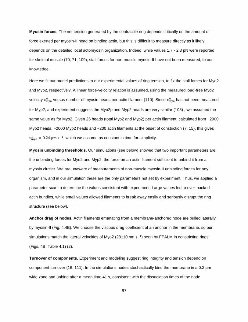
97
Myosin forces. The net tension generated by the contractile ring depends critically on the amount of
force exerted per myosin-II head on binding actin, but this is difficult to measure directly as it likely
depends on the detailed local actomyosin organization. Indeed, while values 1.7 - 2.3 pN were reported
for skeletal muscle (70, 71, 109), stall forces for non-muscle myosin-II have not been measured, to our
knowledge.
Here we fit our model predictions to our experimental values of ring tension, to fix the stall forces for Myo2
and Myp2, respectively. A linear force-velocity relation is assumed, using the measured load-free Myo2
velocity 𝑣myo0 versus number of myosin heads per actin filament (110). Since 𝑣myo
0 has not been measured
for Myp2, and experiment suggests the Myo2p and Myp2 heads are very similar (108) , we assumed the
same value as for Myo2. Given 25 heads (total Myo2 and Myp2) per actin filament, calculated from ~2900
Myo2 heads, ~2000 Myp2 heads and ~200 actin filaments at the onset of constriction (7, 15), this gives
𝑣myo0 = 0.24 μm s−1, which we assume as constant in time for simplicity.
Myosin unbinding thresholds. Our simulations (see below) showed that two important parameters are
the unbinding forces for Myo2 and Myp2, the force on an actin filament sufficient to unbind it from a
myosin cluster. We are unaware of measurements of non-muscle myosin-II unbinding forces for any
organism, and in our simulation these are the only parameters not set by experiment. Thus, we applied a
parameter scan to determine the values consistent with experiment. Large values led to over-packed
actin bundles, while small values allowed filaments to break away easily and seriously disrupt the ring
structure (see below).
Anchor drag of nodes. Actin filaments emanating from a membrane-anchored node are pulled laterally
by myosin-II (Fig. 4.4B). We choose the viscous drag coefficient of an anchor in the membrane, so our
simulations match the lateral velocities of Myo2 (28±10 nm s−1) seen by FPALM in constricting rings
(Figs. 4B, Table 4.1) (2).
Turnover of components. Experiment and modeling suggest ring integrity and tension depend on
component turnover (16, 111). In the simulations nodes stochastically bind the membrane in a 0.2 μm
wide zone and unbind after a mean time 41 s, consistent with the dissociation times of the node

98
components myosin-II essential light chain Cdc8p (38 s) and formin Cdc12p (43 s) (36, 37) (Fig. 4.4C and
Table 4.1). Formins stochastically bind nodes and dissociate from the ring as the node it belongs to
unbinds (Fig. 4.4C). The node-membrane and formin-node binding rates were chosen to fix the mean
total number of nodes and total number of formins to the experimental values (2, 15). Formins nucleate
and grow randomly oriented actin filaments that stochastically shorten due to cofilin-mediated severing
(Fig. 4,4C). Myp2 clusters bind and unbind actin filaments with a turnover time 46 s (Fig. 4.4C) (18).
The component binding, actin polymerization and actin severing rates were adjusted over the course of
constriction to reproduce the gradually changing mean actin filament length and mean densities of Myo2,
Myp2 and formin Cdc12p seen experimentally (Table 4.1) (7, 15).
Running the simulation. The ring, initially 3.7 μm in diameter (11) with actin filaments randomly oriented
parallel to the ring, is evolved using the forward Euler method: the net force on each component is
calculated from the positions at some instant, from which the velocities are calculated and the positions
updated by adding the product of the velocities and the timestep, typically 0.2 s. At every time step,
components are added to and removed from the simulation according to the turnover rules.
99
Figure 4.4. Mathematical model of the fission yeast cytokinetic ring with distinct myosin-II isoforms. (A) Model faithfully implements the node structure of the ring revealed by FPALM. Top, molecularly explicit schematic of the nodes structure (left) and coarse-grained representation of the node used in our model (right), plotted to-scale. In the coarse-grained representation, Rng2p, Cdc15p and Cdc12p are represented by a sphere (brown) and Myo2 heads are represented by an ellipsoid (red). Bottom, FPALM images of Myo2 heads and Cdc15 C-terminus (left) and radial density distributions thereof (right). Images reproduced from (2) except the coarse-grained representation. For details of the model including key parameters, see Table 4.1. (B) Forces in the model. Myo2, localized in membrane-anchored nodes, binds and pulls actin filaments. Myp2 clusters also bind and pull actin filaments but are unanchored to the plasma membrane. Nodes are subject to an anchor drag force resisting their motion along the membrane. α-actinin forms dynamic crosslinks between neighboring actin filaments. (C) Turnover. Myo2 nodes bind the plasma membrane, and afterwards formin Cdc12p dimers bind to membrane-anchored Myo2 nodes. Actin filaments elongate from formin Cdc12p dimers, towards a random direction away from the membrane, and are being stochastically severed, mediated by cofilin. Nodes dissociate from the ring as a whole. Myp2 clusters bind and unbind actin filaments. (D) Schematic illustrating the organization of components in the model, based on a snapshot from a simulation 6 min

100
after constriction onset. In the simulation, the Myo2 dimers and Myp2 molecules are not represented individually as in this schematic, but instead single entities are used each representing a cluster of molecules with appropriate dimensions. (E) Distribution of Myo2, Myp2 and actin in the cross section of the ring. Fluorescence imaging simulated with a 2D Gaussian point spread function with FWHM 100 nm (200 nm) centered on Myo2 nodes (Myp2 clusters), projected in the cross-section plane of the ring. Each actin subunit is represented by a white pixel. Brown line represents the plasma membrane.
Myp2 and Myo2 have distinct organizational roles in the ring
Using the parameters of Table 4.1, in simulations the components of the ring spontaneously organized
themselves into a tight actomyosin bundle whose organization reproduced the experimentally observed
features (Figs. 4.4 and 4.9). Actin filaments were bundled into a region of width and thickness in the
range 128±37 nm (mean ±SD, n = 64 rings at 12 min after onset of constriction), consistent with FPALM
data showing an actin bundle of width and thickness 125 nm (2). A Myp2 ring was generated which lay
inside a Myo2 ring, the Myo2 heads being 26±7 nm (mean ±SD, n = 64 rings at 12 min after onset of
constriction) closer to the membrane than the Myp2 heads (Figs. 4.4 and 4.9) consistent with FPALM
data showing Myo2 heads ~30 nm closer to the membrane than Myp2 heads (19), and confocal
fluorescence microscopy showing a Myp2 ring lying inside a Myo2 ring (11).
The simulations showed that the two isoforms of myosin-II, in addition to providing force (see following
sections), are essential for ring organization and make distinct but complimentary contributions. Myo2 has
two organizational roles. First, Myo2 bundles the outer half of the bundle of actin filaments (i.e., those
filaments closest to the membrane). Second, Myo2 anchors the actin bundle to the membrane. Effective
anchoring required sufficiently strong actin-Myo2 binding, to withstand the Laplace force per unit length ~
𝑇fil/𝑅 tending to straighten a filament with tension 𝑇fil that follows the curvature of the ring of radius 𝑅.
The Laplace force acts centripetally and tries to pull a filament away from the Myo2 it binds. Given ~50
filaments in the cross section, a typical ring tension ~ 600 pN and radius 𝑅~1 𝜇m and ~ 6 Myo2 heads per
micron of actin, a filament has tension 𝑇fil~12 pN and generates a centripetal Laplace load ~ 2 pN per
Myo2 head. The value for the binding strength used in our simulations, 𝑓unbindMyo2
= 10 pN, provides a safety
factor of 5 (Table 4.1).

101
Indeed, for weak actin-Myo2 binding (𝑓unbindMyo2
<10 pN), most actin filaments detached from Myo2 and
became unbundled, taking Myp2 with them. Contrary to experimental observation, rings were improperly
bundled, highly whiskered and did not possess concentric Myo2 and Myp2 rings (Fig. 4.9).
Simulations revealed a somewhat subtler role for Myp2. Like Myo2, Myp2 has a dual bundling-anchoring
role but now primarily for the inner half of the actin bundle (those filaments furthest from the membrane).
Myp2 indirectly anchors this inner portion of the ring by sharing some of these filaments with the
membrane-anchored Myo2 (Fig. 4.4E). In simulations with weak actin-Myp2 binding (𝑓unbindMyp2
< 6 pN),
those inner actin filaments unbound to Myo2 became unbundled, producing a bundle considerably
broader than the experimentally observed value of 125 nm. Thus, despite being unanchored itself, Myp2
indirectly anchors the inner portion of the ring by bridging it to directly anchored outer filaments.
These results revealed the mechanism underlying the radial separation of Myo2 and Myp2. A cluster of
Myo2 heads belonging to a node has a bundling limit of ~ 25 actin filaments, given the cross-sectional
area of the Myo2 capture zone (102 nm diameter) and the inter-actin filament excluded volume range ~
20 nm (Fig. 4.4A and Table 4.1). If one now imagines adding more filaments, the ring will gradually
broaden beyond the Myo2 capture zone without energy loss, as Myp2 can bind the excluded filaments.
Due to the Laplace force on the filaments, broadening occurs radially inward. Thus, the filaments most
distant from the membrane are exclusively bound by Myp2 and hence the Myp2 ring lies within the Myo2
ring.
Ring tension is generated by anchoring actin filament barbed ends to the membrane
As tension is the most important output of a model of the contractile ring, our experimental measurements
of ring tension (Figs. 4.2, 4.3) facilitate a powerful and direct test of our model. We ran simulations and
measured the ring tension as the ring constricted. Using the parameter values of Table 4.1, including best
fit values of the myosin-II stall forces 𝑓Myo2 and 𝑓Myp2, simulations quantitatively reproduced the
experimental tensions (Fig. 4.2), including the increase of tension as the ring constricted up to an angular

102
location of 70° (Fig. 4.5A). This behavior was robust over a range of values of 𝑓Myo2 and 𝑓Myp2 from 1 pN
to 1.9 pN, with best fit values 𝑓Myo2 = 𝑓Myp2 = 𝑋𝑋 pN (lowest chi-square statistic χ2 = 127, Fig.
4.5B)¸similar to the 1.7 – 2.3 pN reported for skeletal muscle (70, 71).
What mechanism generates tension in the simulated rings? The key feature was the anchoring of actin
filament barbed ends to the plasma membrane, via a formin-node linkage (Fig. 4.4), which ensured that
every myosin-actin interaction produced tension in the filament, not compression (Fig. 4.4B). Large lateral
anchor drag forces provided the necessary opposition to the myosin force so that filaments could develop
tension, being sufficient that the lateral node velocities in the membrane lie well below the load-free
myosin-II velocity (240 nm s−1, Table 4.1).
In support of this mechanism, we found that tensions in individual actin filaments decreased
approximately linearly, from a maximum at the anchored barbed end to zero at the free pointed end (Fig.
4.10). This directly follows from the mechanism, since myosin from other nodes is approximately
uniformly distributed along a filament emanating from a given node, and each myosin contributes to
tension in the section of filament from the myosin to the barbed end.
It is simple to show that an approximate formula for the net ring tension due to this mechanism is
𝑇 = 𝑛 [𝑓Myo2(𝑣pol)𝜌Myo2 + 𝑓Myp2(𝑣pol)𝜌Myp2] 𝑙fil/2 (1)
where 𝑓Myo2(v), 𝑓Myp2(v) are the force-velocity relations per head, 𝑛 is the number of heads per Myo2
node or Myp2 cluster, ρMyo2 and ρMyp2 are the densities along the ring and lfil the mean actin filament
length. This result reflects the fact that the relative myosin-actin velocity is approximately the
polymerization velocity 𝑣pol, which is much greater than the velocity of the nodes, and the mean distance
from the myosin binding site to the barbed end is 𝑙fil/2.
In this formula we used the experimentally measured myosin-II densities and actin filament lengths
through constriction (7, 15) and the values of 𝑣pol used in the simulation (Table 4.1). The predicted

103
tension increases continuously as the ring constricts and is close to both the simulated and experimental
tensions (Fig. 4.5A). The simple formula neglects variations in actin length, myosin inhomogeneities,
component motions, crosslinking effects and other imperfections in ring organization, but its ability to
capture the essential features of the tension profile shows that the essential mechanism is the lateral
anchoring of actin filament barbed ends, Fig. 4.4B.

104

105
Figure 4.5. Ring tension is produced by Myo2 and Myp2 pulling on barbed-end-anchored actin filaments. (A) Comparison of analytically calculated WT ring tensions (red) with experimentally measured (blue, data from Fig. 3C) and simulation-predicted tensions (black, mean ± SD, n = 64 simulations,
parameters as in Table 4.1). The analytical calculation uses Eq. 1 and 𝜌Myo2, 𝜌Myp2 and 𝑙fil were fitted
with an interpolating spline based on data points obtained from (7) and (15). (B) Determining Myo2 and Myp2 force by comparing model predictions of ring tension (black, mean ± SD, n = 8 simulations for each combination of Myo2 and Myp2 force per head, fMyo2 and fMyp2) to experiment (blue, data from Fig. 4.3C). Other simualtion parameters as in Table 4.1. Best-fit parameters fMyo2 = fMyp2 = 1.6 pN (red box) are obtained by minimizing the Chi-squared statistic between the two tension profiles, using the variance in the experimental data as the error.
Myo2 anchors the ring to the membrane while Myp2 bundles the ring, and each contributes ~ 60%
and ~ 40% to ring tension, respectively
A powerful feature of our molecularly explicit simulation is its ability to implement mutations of ring
components with some detail. Thus, we sought to isolate the role of the conventional myosin-II isoform
Myo2 by simulating rings with the temperature-sensitive myo2-E1 mutation, and comparing with
experiment. Rings in myo2-E1 cells are dramatically affected by the mutation: (i) here, we found the ring
tension was ~ 65% reduced from wildtype (Fig. 4.3C), and (ii) a previous study found a disrupted ring
organization, with actin filament bundles detaching from the membrane and forming straight bridges
containing Myp2 (11).
Myo2p-E1 has minimal ATPase activity even at the permissive temperature (20). In vitro, Myo2p-E1 binds
actin only weakly (20, 21), and when it does bind with the help of methylcellulose it fails to translocate
actin (21). Accordingly, we implemented Myo2p-E1 in our simulations with zero pulling force on actin, and
with an unbinding force from actin 𝑓unbindMyo2p−E1
= 6.25 pN, reduced from the wild type value of 10 pN. This
value was chosen to match the number of bridges seen experimentally.
In simulations of myo2-E1 rings the tension profile throughout constriction, 𝑇(𝜙), was close to the
experimental profile (Fig. 4.6) and the mean tension was �̅� = 247 ± 137 pN, averaged over the portion of
the constriction trajectory sampled by the wild type experimental measurements (100 < 𝜙 < 700, Fig.
4.2C). This value is ~ 35% of the mean simulated wild type tension, 703 ± 320 pN. Thus, the impact of

106
the mutation in simulations matched that in experiments, where mean ring tensions in myo2-E1 cells were
~ 35% of wild type (640 pN and 220 pN for wild type and myo2-E1, respectively (Fig. 4.3C)).
It is interesting to compare these simulated tensions, generated by Myp2 only, to the contribution of Myp2
in wild type simulations. In normal rings, Myp2 constitutes ~ 35% of the total myosin-II present and our
simulations used equal stall forces for the two isoforms, so that naively Myp2 generates ~ 35% of the total
ring tension, or a mean of ~ 220 pN. This is very close to the mean tension in simulated myo2-E1 rings,
247 pN.
The ring organization was also impacted by the myo2-E1 mutation. As seen experimentally, simulated
rings developed well-bundled bridges dressed with Myp2 (Fig. 4.6). Importantly, the bridges, while
disconnected from the membrane and straight, were otherwise completely normally bundled. We stress
that the comparison of simulated tensions and organization to experiment is a stern test of the model, as
no free parameters are involved other than the Myo2 unbinding parameter.
Thus, Myo2 anchors the ring to the plasma membrane, by itself being indirectly anchored to the
membrane, and by binding and bundling actin filaments (Fig. 4.4B). Due to the weakened binding of actin
in myo2-E1 cells, the ring detaches from the membrane at numerous locations, but remains attached to
the membrane as a whole (Fig. 4.6).
These results show that Myp2 is an important bundler of the ring. Despite the weak Myo2 binding of actin
in simulated myo2-E1 rings, the ring remains well-bundled even in bridges containing no Myo2 (all Myo2
is left behind in membrane-anchored nodes). Thus, the unanchored Myp2 can bundle the entire ring
cross-section on its own, helped by its long tail which endows it with a large range as a crosslinker and its
ability to roam freely.
The results also illuminate the tension mechanism. Even in the bridges, Myp2 exerts its normal wild type
tension contribution without difficulty. Thus, tension does not require lateral anchoring of myosin-II, since
Myp2 is unanchored. The requirement is the lateral anchoring of actin barbed ends to the membrane,
providing resistance to myosin pulling.

107
Figure 4.6. Myo2 and Myp2 collaborate to generate tension and organize the ring. Simulation parameters as in Table 4.1, unless otherwise specified. (Top) Comparison of experimental ring tensions (data from Fig. 4.3C) with ring tensions produced by simulations in wild-type, Δmyp2, and myo2-E1 cells (mean ± S.D., n = 32 simulations each), versus ring location ϕ. (Center) Schematics illustrating the organization of components in the model, based on snapshots from wild-type, Δmyp2, and myo2-E1 simulation 9 min after constriction onset. In wild-type simulations, Myo2 and Myp2 collaborate to bundle actin filaments, while in Δmyp2 simulations a significant fraction of filaments are unbundled and chaotically oriented in all directions, and in myo2-E1 simulations bundles of actin filaments peel away from the Myo2-E1p ring with Myp2. (Bottom) Simulated dual-color fluorescence microscopy images of Myo2p and Myp2p in wild-type, Δmyp2, and myo2-E1 rings 9 min after constriction onset. In wild-type simulations, Myp2 ring lies ~ 30 nm within the Myo2 ring. In myo2-E1 simulations Myp2 localizes to the actin ring or actin bundles that peel away from the Myo2-E1p ring.
Myp2 increases the ring’s tension generating capacity
Next we use the simulation to examine the role of Myp2, by comparing with our tension measurement of
Δmyp2 cells. To do this we ran simulations with Myp2 entirely absent.

108
Myp2 is an unconventional myosin-II and to the authors’ best knowledge the only one that does not form
dimers, since sedimentation studies showed the Myp2p tail is monomeric (108). There’s strong evidence
that Myp2 is not anchored to the plasma membrane: in cells treated with 8 μM Latrunculin-A, the Myp2
ring disintegrates, suggesting its localization to the ring entirely depends on actin (18); a fraction of Myp2
is on actin bundles that break away from the membrane in myo2-E1 cells (11); superresolution FPALM
showed Myp2 further away from the membrane than Myo2 (19). Deconvolution microscopy suggested
that Myp2 is organized in clusters unanchored to the plasma membrane (18). Given that Myp2 is
organized so differently in the ring compared to Myo2, why does it contribute to ring tension equally (per
head) compared to Myo2? We will answer this question with simulation.
We ran simulations with Myp2 entirely absent and found that the mean tension of Δmyp2 rings �̅� = 250 ±
100 pN and its evolution as the ring constricts 𝑇(𝜙) agrees qualitatively with our experimental results, with
no fitting parameters (Fig. 4.6). In particular, ring tension drops ~ 60% below WT, comparable to
experiments where tension drops ~ 40% below WT; tension increases ~ 100% throughout constriction as
seen in experimentally.
Our model shows ring organization in Δmyp2 cells is totally messed up. Chaotic unbundled individual
filaments are oriented in all directions (Fig. 4.6). However, a bundle reduced in thickness of ~ 23 filaments
survives, anchored to the membrane and bundled by Myo2. This is because (i) filaments grow in all
directions, and a fraction does not pass through the reach of any Myo2. Most of such filaments would
have been bundled by Myp2 clusters whose size is about twice of Myo2 clusters in WT, but not in Δmyp2
rings. (ii) filaments have a repulsive potential of range 20 nm (diameter), so only ~ 25 filaments can fit in
the capture zone of Myo2 clusters, and the rest of the 50 filaments in the ring cross section cannot fit in
and thus cannot interact with Myo2.
We have shown that Myp2 is indispensable to proper bundling of the ring. In its absence, only ~ 25 of 50
filaments in the cross section are properly bundled by Myo2, and the rest fly all over the place. Thus, if
you want to increase the girth of the ring to contain more actin filaments and more myosin beyond the
capacity of Myo2, the bundling agent Myp2 is needed. It allows ~ 25 more filaments to be bundled and

109
approximately doubles tension. These additional ~ 25 filaments are indirectly anchored to the membrane
by Myp2, which shares the original ~ 25 filaments with membrane-anchored Myo2.
These ~ 25 filaments are crucial for increasing the ring’s tension generating capacity. Given the maximal
ring tension close to the end of constriction ~ 1000 pN, if only 25 filaments bear this tension, each would
bear ~ 40 pN on average. Because tension increases linearly from the pointed end in each filament (Fig.
4.10), the average tension at the barbed ends are ~ 80 pN, close to the fracture limit of 100 pN (69).
Given the fluctuations in actin length and myosin distribution, the tension at the barbed ends of many
actin filaments would exceed the fracture limit and these actin filaments will fracture. Therefore, without
the help of Myp2 to bundle more actin filaments, the ring does not have enough capacity to generate the
experimental tension.

110
Figure 4.7. Furrowed protoplasts are variable in size, have higher membrane tension, and recruit septum synthesis machinery to cytokinetic rings. (A) Histogram of furrowed protoplast diameters (same protoplasts as in Figure 4.2, n = 31). Protoplasts vary in size with average diameter Dp = 5.9 ± 0.4
𝜇m (mean ± SD). (B) Comparison of measured membrane tension in furrowed protoplasts containing rings (same protoplasts as in Figure 4.2, n = 31) versus nonfurrowed, spherical protoplasts lacking rings (n = 9). Furrowed mitotic protoplasts have membrane tension 𝜎1 = 0.63 ± 0.16 mN m-1 (mean ± SD), significantly greater than the nonfurrowed interphase protoplast membrane tension 𝜎 = 0.46 ± 0.19 mN m-1 (p = 0.014, two-tailed t-test). Error bars indicate SD. Membrane tension for nonfurrowed protoplasts are not significantly different from that measured previously in (16) (p = 0.18, two-tailed t-test). (C) Confocal microscopy images of one protoplast with cytokinetic ring expressing fluorescently-tagged myosin light chain Rlc1p-tdTomato (center), 𝛽-glucan synthase GFP-Bgs1p (left), and spindle pole body marker Sad1p-GFP (left). Mitotic protoplasts with sliding myosin rings colocalize with GFP-Bgs1p (overlay, right). Sum intensity projections are displayed. Scale bar = 2 𝜇m.

111
Figure 4.8. Cells tensions increased at rates in the range ~0.1 to ~5% per min. Contractile ring tension versus time for individual rings as they constrict (solid lines). Each color corresponds to a different cell. Tensions are normalized to the initial value. The dashed line represents the estimated time-dependence of ring tension in cells used for single tension measurements only, based on the tensions measured in Fig. 4.2C and an assumed constriction time in protoplasts of 50 min (16).

112
Figure 4.9. Integrity of the ring requires sufficiently strong binding of myosin-II to actin. Each panel shows distribution of Myo2, Myp2 and actin in the cross section of the ring. Fluorescence imaging simulated with a 2D Gaussian point spread function with FWHM 102 nm (200 nm) centered on Myo2 nodes (Myp2 clusters), projected in the cross-section plane of the ring. Each actin subunit is represented by a white pixel. Brown line represents the plasma membrane. Text above each panel indicate the separation of Myo2 and Myp2, calculated as the difference of the medians of the distances between Myo2/Myp2 and the plasma membrane, and the spread of 90% of actin subunits in the direction perpendicular to the membrane. Shaded area indicates simulations satisfying (i) the spread of 90% of actin subunits in the direction perpendicular to the membrane is between 115 nm and 135 nm, (ii) separation of Myo2 and Myp2 is between 25 nm and 35 nm. Red box indicates the best set of parameters, to be used from this point onward in the paper. Simulation parameters as in Table 4.1 unless otherwise specified.

113
Figure. 4.10. Tension in actin filaments increases approximately linearly as a function of the distance from the pointed end. Simulation parameters as in Table 4.1. Tension (mean ± SEM) was measured in a simulated ring at t = 1 min after onset of constriction and averaged over n = 193 filaments. Weighted linear fit was performed with inverse SEM as weights. Some filaments have length less than 2.5 μm, and data from these filaments contribute to the left part of the plot.
iii. Discussion
Constriction rate is not a proxy for ring tension
Constriction rate is not a proxy for ring tension. Constriction rates suggest that Myp2 is the most important
of the two isoforms in the ring for constriction, since 𝛥myp2 cells constrict rings at only ~75% of the wild-
type rate compared to the normal constriction rate in myo2-E1 cells (11). However, on measurement of
ring tensions we find a very different picture: in fact, the tension contribution of Myo2 (~ 60%) exceeds
that of Myp2 (~ 40%).
Previous studies of the cytokinetic ring tension
Measuring the cytokinetic ring tension is challenging because the ring is not mechanically isolated.
Previous efforts used echinoderm embryos, where the cytokinetic ring is connected to an extended
actomyosin cortex whose tension opposes ring constriction (24, 25, 85). Indeed, defining the precise

114
boundary between the equatorial ring and the cortex is difficult. From the bending of a microneedle,
Rappoport measured the net inward radial force due to the ring and the cortex (23, 86) and Hiramoto
refined the technique with a second reference needle (87). A net force at the furrow of tens of nN was
also measured by Hiramoto, from the deformation of a ferrofluid droplet (24).
In another approach, Yoneda and Dan measured the cortical tension from the axial force to compress
dividing echinoderm eggs and inferred the minimum ring tension required for ingression from a force
balance at the furrow (25). The lower bound peaked at ~ 60 nN and decayed over the course of
constriction. Hiromoto used a similar procedure to estimate bounds on the ring tension in sea urchin eggs
that peaked at ~ 45 nN before decaying (24). However, in these analyses the cortical tension at the poles
was used in the force balance at the furrow, the volume of the cell was assumed constant, and to
estimate the furrow angles the lobes flanking the furrow were assumed to be equal spherical caps. In fact
the lobes are not spherical, suggesting gradients of cortical tension (24, 112). Further, cortical tension
could be increased by the axial compression used in the measurement (112). A similar method yielded a
bound of ~7 nN for the ring tension of the amoeba Dictyostelium, using micropipette aspiration to
measure interphase cortical tension and assuming equal lobes with spherical cap shapes (88). However,
the lobes are far more irregular than the rounded shapes in echinoderm eggs.
These historic studies yielded important information on forces at the ingression furrow, but invoked
uncontrolled approximations on the cortical tension and furrow geometry. Moreover, the end results were
not the ring tensions but either the minimum tension required to overcome cortical contractility at the
poles, or the ring tension corrected by a negative contribution from cortical tension. The difficulties
encountered stem from the strong mechanical interactions of the ring with the actomyosin cortex.
The fission yeast protoplast is a model system to measure cytokinetic ring tension
Here we developed a method to measure the fission yeast cytokinetic ring tension with minimal
assumptions. An organism with a cell wall might seem poorly suited, as constriction of the ring in yeast is

115
tightly coupled to septation, the inward growth of new cell wall behind the constricting ring (113).
However, the plasma membrane of fission yeast lacks a continuous actin cortex (90, 114), so removing
the cell wall results in a contractile ring that appears mechanically isolated other than interactions with the
plasma membrane (1, 16, 17). Membrane tension, unlike contractility-generated cortical tension, arises
passively and is expected to be spatially uniform. The almost perfectly spherical lobe shapes in furrowing
protoplasts corroborates this, supporting our assumption that the membrane tension near the ring equals
the value measured at the micropipette (Fig. 4.1). Further, we estimate that cytoplasmic viscous forces
provide insubstantial resistance during constriction in normal yeast cells, and even less resistance in
protoplasts where rings slide laterally.
Thus, the furrowing force from ring tension in yeast protoplasts is likely opposed only by membrane
tension. Direct measurement of the plasma membrane tension, furrow angles and ring radius yields the
ring tension from a simple force balance (Fig. 4.1B).
Several observations suggest that contractile rings in protoplasts are representative of intact cells. While
only a fraction of protoplasts assemble rings (<5%), the rings closely resemble those in intact cells. Both
are assembled from precursors (“nodes”) that move with similar velocities and have similar drag
coefficients, the time evolution of the myosin-II concentration in protoplast rings (Fig. 4.3C) is similar to
that in intact cells (16), and most contractile ring gene products remain in cytokinetic rings following
removal of the cell wall (1, 17).
The cytokinetic ring tension is ~ 50-fold lower in fission yeast than in echinoderm embryos, but
the stresses are similar
We measured tensions in the fission yeast ring in the range 230-1200 pN (Fig. 4.2A), ~50-fold smaller
than values reported for echinoderm embryos, 10-60 nN. However, the fission yeast ring cross-sectional
area ~0.027 m2 (7) is ~ 60-fold less than the ~1.6 μm2 of rings in Arbacia sea urchin embryos, for
example (26). This leads to similar stresses, ~ 24 nN/m2 (assuming a 650 pN tension for yeast) and ~28

116
nN/m2 (assuming 45 nN for T. toreumaticus the sea urchin embryo (24)). The ring stress of ~8 nN/μm2
is similar in D. discoideum cytokinetic rings, calculated from a tension of 7 nN (88), a ring width of 2.7 m
and a cortical thickness of 0.35m (115). The consistency of cytokinetic ring stresses across several
organisms suggests similarities in the actomyosin organizations and tension-generating mechanisms.
Septum synthesis sets the constriction rate
The ring tensions we report are extremely small compared to the high modulus of the cell wall material. In
yeast the ring is attached to the plasma membrane at the base of the furrow, adjacent to the leading edge
of the ingrowing septum (31), so that constriction of the ring and the septum are strictly coupled. Taking a
ring width w ~ 0.1 𝜇m (50), the mean tension T ~ 650 pN (Fig. 4.2A) generates an inward radial stress
T/wR ~7 kPa at the leading edge of the septum for a typical ring radius R ~1 μm. The modulus of the
septum has not been measured, but using the value ~30 MPa for cell wall (116), this stress would
produce negligible strains in the septum of ~ 0.02%.
In other words, the hole in the center of the disk-shaped septum can constrict only if more septum
material is grown, so synthesis of the leading edge of the septum by glucan synthases in the plasma
membrane (117, 118) sets the rate of ring constriction. The situation has parallels in animal cells, where
the constricting ring may actively drive constriction. However, a competing theory is that constriction
results from the release of tension in the polar regions of the cortex (25, 119). For fission yeast, the ring
tension is negligible compared to the restraining force due to its attachment to the septum, and hence
constriction results from inward septum growth. Of course, ring tension may nonetheless influence the
constriction rate if septum synthesis is mechanosensitive, but this is a subtler effect than in the traditional
view where tension directly drives constriction.
The Myosin-II isoforms Myo2p and Myp2 account for all of the ring tension

117
Compared to wild type, the ring tension was ~ 35% in cells lacking Myo2p activity, and ~ 60% in Myp2
deletion mutants (Fig. 4.3B). The simplest mechanism consistent with this data is that Myo2 contributes ~
60% of the ring tension and Myp2 the remaining ~ 40%, almost independently. These tensions are in the
same ratio as the numbers of each isoform in the ring (7), suggesting a similar exerted force per
molecule. We used our model to calculate that both isoforms produce 1.6 pN of force per head (Fig.
4.5B), similar to the 1.7 – 2.3 pN reported for skeletal muscle (70, 71). Cells are viable after the Myo2p
and Myp2p motor domains are swapped (108), suggesting similar motor activities and consistent with our
conclusion that the isoforms exert similar forces per head.
Consistent with myosin-II being the determinant of ring tension, the tension increased ~ 2-fold as the ring
constricted through an angle ~ 700 (Figs. 4.2), correlated with an increase in myosin-II concentration in
the ring (7). We found similar correlations in myo2-E1 and 𝛥myp2 cells (Figs. 4.3 and ref. (7)). Ring
tension may increase during constriction in other organisms such as Dictyostelium (88) and N. crassa
(120), where myosin density in the ring also increases. On the other hand the reported tension increased
and then decreased during cleavage of echinoderm eggs (24, 25).
The myosin-driven mechanism of tension production described by our model is supported by its ability to
reproduce experimental tensions (Fig. 4.5), and the fact that myosin-II accounts for all of the tension.
Models of cytokinesis in other cells include proposals that actin depolymerization generates tension (41,
45). In our model turnover of actin and other components does not itself produce force, but nevertheless
plays a critical role by enabling the ring to continuously disassemble and reassemble its tension-
generating organization as it constricts (16).
Anchoring actin barbed ends to the plasma membrane is critical for tension generation, but not
anchoring of myosin
It has long been under debate how tension is generated in the ring, given that a random actomyosin
bundle generates none. A mechanism based on barbed end anchoring of actin filaments has been

118
proposed (16), but only recently did FPALM experiments show that formin Cdc12p (at the barbed ends of
actin filaments) is colocalized with Myo2 in membrane-anchored cytokinetic nodes (2), which supports
this mechanism.
In this study we provide even stronger support of this mechanism – our model faithfully implements the
colocalization of Cdc12p and Myo2 in cytokinetic nodes. We reproduced experimentally observed mean
tension and evolution of tension during constriction (Fig. 4.5).
Interestingly, we found that unanchored Myp2 contributes as much tension as Myo2 on a per molecule
basis (Figs. 4.3 and 4.5), suggesting that anchoring of myosin is not required for tension generation. This
is further validated in myo2-E1 simulations, where segments of the actin ring break away from the
membrane, taking Myp2 with them (Fig. 4.6). For these segments (bridges) all myosin-II is unanchored,
yet Myp2 is generating tension as efficiently as WT.
Myo2 and Myp2 collaborate to bundle and anchor the ring, transducing ring tension to radial
forces on the plasma membrane
Merely anchoring barbed ends is not sufficient to anchor actin filaments, because (1) no experimental
evidence suggest that they necessarily grow parallel to the plasma membrane, and (2) Laplace force, due
to the tension that actin filaments carry, pulls filaments radially inward, away from the membrane. Actin
filaments need to be anchored all along its length.
Neither is merely anchoring actin barbed ends sufficient to transduce ring tension to the plasma
membrane as a radial force. A ring tension of ~ 600 pN gives a total radial Laplace force of ~ 3800 pN
shared by ~ 200 nodes, i.e. ~ 19 pN per node. If this is solely due to actin filaments making an angle with
the membrane (pulling down on the membrane), the angle would need to be ~ 30° because each filament
carries ~ 40 pN of tension at the barbed end. Such a large angle is drastically larger than that during
assembly (~ 8°, (48)) and is unlikely.

119
What provides additional anchoring except at the barbed ends of actin filaments? Although a large
number of proteins bind to F-actin and some directly or indirectly bind to the membrane, a key
observation that some actin filaments break away from the membrane in myo2-E1 cells suggest that
Myo2 plays this role (2). It is also a natural role for Myo2 because it is anchored to the membrane and
binds actin.
However, Myo2 cannot perform this function on its own, primarily due to the limited size of Myo2 clusters
in nodes ~ 100 nm in diameter (2), which makes it only able to bundle ~ 25 filaments out of a total of ~50
in the cross section to the membrane, assuming 10 nm spacing between filaments. This is seen in our
Δmyp2 simulations where Myo2 acts on its own (Fig. 4.6).
Myp2, on the other hand, has a long tail of ~130 nm (108), so presumably Myp2 clusters can be of
diameter ~ 200 nm, much larger than Myo2. This makes them large enough to bundle the entire actin ring
(~ 125 nm in diameter, (2)). However, Myp2 is unanchored and can only anchor the ring to the membrane
by binding to those filaments anchored by Myo2. In fact, “bridges” of actin bundled by Myp2 break away
from the membrane in myo2-E1 cells where the ability of Myo2 to anchor filaments to the membrane is
compromised (11).
An unanchored myosin-II isoform is necessary to beef up the ring
We have shown that anchored Myo2 can only bundle ~ 25 filaments due to its limited size, and if you
want to increase tension by adding more filaments, an unanchored myosin-II isoform, i.e. Myp2, is
indispensable to proper bundling of the ring.
What about increasing tension by adding myosin only, but not adding more filaments? This would not be
feasible since the actin filaments are already close to fracture limit. Given ~ 1000 pN of tension (close to
the end of constriction) carried by 50 filaments in the cross section, each filament carries ~ 20 pN tension
on average and ~ 40 pN close to its barbed end (tension increases linearly on a filament from the pointed
end to the barbed end, see Fig. 4.10). Since filaments fracture at ~ 100 pN (69), this only leaves a safety

120
factor 2.5 against fluctuations of all sources (e.g. filament lengths, density of myosin at various positions
along the ring). Further increasing tension carried on each filament would cause frequent fractures.
In summary, you need an unanchored second myosin-II isoform to broaden the ring and add more
filaments away from the membrane. Even though unanchored, such myosin can still exert tension as long
as actin filaments are anchored at the barbed ends and bundled, directly or indirectly, to the membrane.
Table 4.1. Key parameter values of the ring simulation.
Symbol Meaning Value at onset of
constriction Legend
Ring binding zone width 0.2 μm (A)
𝜌Cdc12p Density of formin Cdc12p dimers along the ring 20 μm-1 (B)
𝑘Cdc12poff Formin off rate 0.023 s-1 (±0.007 s-1) (C)
𝜌Myo2 Density of Myo2 nodes along the ring 18 μm-1 (D)
𝜌Myp2 Density of Myp2 clusters along the ring 12.5 μm-1 (E)
𝑘Myo2off
Myo2 off rate 0.026 s-1 (F)
𝑘Myp2off Myp2 off rate 0.022 s-1 (G)
𝑓Myo2stall Myo2 stall force per head 1.6 pN (H)
𝑓Myp2stall Myp2 stall force per head 1.6 pN (H)
Major axis of Myo2 capture zone 132 nm (I)
Minor axes of Myo2 capture zone 102 nm (both) (I)
Diameter of Myp2 capture zone 200 nm (J)
𝜌actinin Density of α-actinin dimers along the ring 25 μm-1 (K)
𝑘actininoff
α-actinin off rate 3.3 s-1 (L)
Actin filament mean length 2.5 μm (M)
rsev Cofilin-mediated severing rate per unit length on
actin filament 0.93 μm-1 min-1 (N)
vpol Formin-mediated actin polymerization rate 127 nm/s (N)
lp Actin filament persistence length 10 μm (O)
Anchor drag coefficient per node 2 nN·s/µm (P)

121
Legend:
Values in parentheses are standard deviations or ranges for experimentally measured values, and standard errors for fitting parameters.
(A) We assume that new constriction nodes bind the leading edge of the septum (ingrowing cell wall). The septum has width ~ 0.2 μm (118).
(B) Ref. (15)
(C) Ref. (37). Together with the value for ρCdc12p, this gives a formin binding rate of rCdc12p = 0.46 μm-1·s-1 at the onset of constriction.
(D) Calculated from 2900 Myo2p in a 10 μm long ring at the onset of constriction (7), and 8 Myo2 dimeric dimers per node (2).
(E) Calculated from 2000 Myp2p in a 10 μm long ring at the onset of constriction (7), and 16 Myp2 dimeric dimers per cluster, determined in this study.
(F) From FRAP measurements of myosin light chain Cdc4p (36). Together with the value for 𝜌Myo2, this
gives a Myo2 binding rate of rMyo2 = 0.47 μm-1·s-1 at the onset of constriction.
(G) From FRAP measurements of Myp2p (18). Together with the value for 𝜌Myp2, this gives a Myp2
binding rate of rMyp2 = 0.27 μm-1·s-1 at the onset of constriction.
(H) From fitting of experimental tension profiles (Fig. 4.5) in this work.
(I) From the distribution of Myo2 heads measured in FPALM (2).
(J) From the apparent size of Myp2 clusters measured in deconvolution microscopy (18).
(K) Ref. (7).
(L) Ref. (121).
(M) The ratio of total actin filament length (500 μm) and the number of formin Cdc12p dimers (200) (15).
(N) From fitting of actin turnover time and mean filament length in this work.
(O) Refs. (49, 59).
(P) Chosen such that model prediction of node velocity agrees with Myo2 node velocity (28 ± 10 nm s-1) measured by FPALM (2).

122
Table 4.2. List of S. pombe strains used in this study
Strain Genotype Reference
AR581 h rlc1-tdTomato-natMX6 sad1-GFP-kanMX6 bgs1Δ::ura4+
Pbgs1+::GFP-bgs1+:leu1+ leu1-32 ura4-D18 his3-D1 ade6-M21X
Ref. (31)
AR619 h Δmyp2::his7+ rlc1-tdTomato-natMX6 sad1-GFP-kanMX6
bgs1Δ::ura4+ Pbgs1+::GFP-bgs1+:leu1+ leu1-32 ura4-D18 his3-D1
ade6-M21X
Ref. (31)
CL4 h- rlc1-3GFP ade6-M216 his3-D1 leu1-32 ura4-D18 Ref. (29)
CL55 h+ myo2-E1 Rlc1-tdTomato-NatMX6 Sad1-mEGFP-KanMX6 Ref. (104)
QC240 h- rlc1-tdTomato-natMX6 ade6-M210 leu1-32 ura4-D18 41xGFP-
CHD-Leu
Ref. (122)

123
Chapter 5
V. Conclusions
In this thesis, I have made significant advance towards a detailed understanding of the mechanical
principles governing the actomyosin contractile ring that drives or regulates cytokinesis. I have taken two
theoretical approaches, (1) molecularly detailed computational models which capture as many
experimentally revealed facts as possible, and (2) highly coarse-grained (mean-field) analytical
calculation which reveals the most fundamental aspects of the ring, tension generation and structural
stability. Our models are highly informed and constrained by the latest experimental findings of the
structure and tension of the ring, achieved in the O’Shaughnessy, Karatekin and Pollard groups. The
following conclusions are established in this thesis.
i. The cytokinetic ring tension requires anchoring of actin filament barbed-ends
While the interaction between two main components in the ring, myosin-II and actin filaments, has been
well-characterized in general and especially in muscle, how these components work as a large ensemble
to generate tension is controversial. Especially confusing is the fact that the fission yeast cytokinetic ring
does not possess a periodic (sarcomeric) order of actin and myosin, which intuitively would not be
contractile.
In Chapter 2, I modeled the ring in a remarkable situation, being partially anchored and partially
unanchored. My work strongly supports that ring tension is generated by anchoring actin filament barbed-
ends. A simple analytical calculation shows that the unanchored segment has zero tension, which is not
surprising as it encounters minimal resistance, and even an unanchored segment from a sarcomeric ring
would behave the same. However, it is remarkable that unanchored segments of various lengths all
shorten at the same rate, inconsistent with a sarcomeric ring. Further, our model reveals a novel reeling-
in mechanism that is based on barb-end anchoring of actin filaments, which reproduces not only this
length-independence, but also the constriction rate, in a quantitative manner. This piece of work has a

124
profound implication on the ring in its native environment, i.e. fully anchored in an intact cell. It strongly
supports the anchoring hypothesis that the ring tension requires anchoring of actin filament barbed ends.
In Chapter 3, together with S. Thiyagarajan, we developed a mathematical model based on the anchoring
hypothesis and the latest experimental findings of the node organization of the ring. The model
successfully reproduces experimentally measured ring tension values and explains why nodes move
bidirectionally. More details of tension generation are revealed: the ring consists of two contra-rotating
families of nodes, and inter- and intra-family interactions between nodes both contribute to half of the total
ring tension. When the nodes are unanchored from the plasma membrane, tension generation becomes
less efficient because actin filaments are only anchored to Myo2 as nodes, but not to the plasma
membrane. This halves ring tension.
Therefore, we conclude that the ring generates tension by myosin-II pulling on barbed-end anchored actin
filaments, confirming the anchoring hypothesis.
ii. A stochastic sliding filament mechanism involving two classes of nodes generates tension
Recent superresolution microscopy revealed that the barbed ends of actin filaments are anchored via
formin Cdc12p to cytokinetic nodes, membrane-anchored protein complexes including myosin-II Myo2
(2). In Chapter 3, we find that typical nodes having one actin filament can be grouped into two classes
according to the direction of the actin filament, and continuously slide in opposition to one another,
forming transient actin-myosin interaction pairs everywhere along the ring. Such a stochastic sliding
filament mechanism has the same fundamental principle as the sliding filament mechanism used in
muscle, but unlike sarcomeres in muscle that are stable, here the tension-generating units are
stochastically and transiently formed.

125
iii. Two myosin-II isoforms complement each other to generate tension and endow structural
integrity to the ring
The stochastic sliding filament mechanism can be at work only in an near-1D, well-bundled ring, a
structure that is optimized for tension generation. In Chapter 4 we find that Myo2 serves as a direct
anchor of the actomyosin ring and bundles half the ring, while Myp2 bundles the entire ring and indirectly
anchoring it. Hence Myo2 and Myp2 complement each other to maintain organizational structure of the
ring. Further, we show that only half the actin bundle can fit into the range of Myo2 clusters, imposing an
intrinsic limit of tension generated by Myo2 and actin alone. Properly organizing the second half of the
actin bundle requires the bundling and indirect anchoring functions of Myp2. Given the structural integrity
of the ring, Myo2 and Myp2 cooperate to generate tension, contributing approximately the same amount
per myosin-II head.
iv. Component turnover and anchoring protects the ring from intrinsic contractile instabilities
In Chapter 3, we find that a characteristic contractile instability affects the cytokinetic ring: a local
fluctuation that increases the actin or myosin density causes a higher local contractile force, which draws
in more actin and myosin, leading to run-away aggregation. Without turnover-mediated restoration, this
instability is detrimental to the ring’s structure and its ability to generate tension. Turnover is able to
preserve organizational homeostasis provided that it is faster than the aggregation caused by contractile
instability, which is slowed by the node anchor drag in the membrane. Therefore, the ring is stabilized by
anchoring of components to the plasma membrane and component turnover.

126
References
1. Mishra M, et al. (2013) In vitro contraction of cytokinetic ring depends on myosin II but not on actin dynamics. Nat. Cell Biol. 15(7):853-859.
2. Laplante C, Huang F, Tebbs IR, Bewersdorf J, & Pollard TD (2016) Molecular organization of cytokinesis nodes and contractile rings by super-resolution fluorescence microscopy of live fission yeast. Proceedings of the National Academy of Sciences of the United States of America 113(40):E5876-E5885.
3. Schenk C, Bringmann H, Hyman AA, & Cowan CR (2010) Cortical domain correction repositions the polarity boundary to match the cytokinesis furrow in C. elegans embryos. Development 137(10):1743-1753.
4. Knoblich JA (2010) Asymmetric cell division: recent developments and their implications for tumour biology. Nat. Rev. Mol. Cell Biol. 11(12):849-860.
5. Mabuchi I, Tsukita S, Tsukita S, & Sawai T (1988) Cleavage furrow isolated from newt eggs - contraction, organization of the actin filaments, and protein components of the furrow. Proc. Natl. Acad. Sci. USA 85(16):5966-5970.
6. Goss JW, Kim S, Bledsoe H, & Pollard TD (2014) Characterization of the roles of Blt1p in fission yeast cytokinesis. Mol. Biol. Cell 25(13):1946-1957.
7. Wu JQ & Pollard TD (2005) Counting cytokinesis proteins globally and locally in fission yeast. Science 310(5746):310-314.
8. Schroeder TE (1975) Dynamics of the contractile ring. Soc. Gen. Physiol. Ser. 30:305-334. 9. Maupin P & Pollard TD (1986) Arrangement of actin filaments and myosin-like filaments in the
contractile ring and of actin-like filaments in the mitotic spindle of dividing HeLa cells. J. Ultrastruct. Mol. Struct. Res. 94(1):92-103.
10. Bezanilla M, Wilson JM, & Pollard TD (2000) Fission yeast myosin-II isoforms assemble into contractile rings at distinct times during mitosis. Curr. Biol. 10(7):397-400.
11. Laplante C, et al. (2015) Three Myosins Contribute Uniquely to the Assembly and Constriction of the Fission Yeast Cytokinetic Contractile Ring. Curr. Biol. 25(15):1955-1965.
12. Green RA, Paluch E, & Oegema K (2012) Cytokinesis in animal cells. Annu. Rev. Cell Dev. Biol. 28:29-58.
13. Pollard TD & Wu JQ (2010) Understanding cytokinesis: lessons from fission yeast. Nat. Rev. Mol. Cell Biol. 11(2):149-155.
14. Lee IJ, Coffman VC, & Wu JQ (2012) Contractile-ring assembly in fission yeast cytokinesis: Recent advances and new perspectives. Cytoskeleton 69(10):751-763.
15. Courtemanche N, Pollard TD, & Chen Q (2016) Avoiding artefacts when counting polymerized actin in live cells with LifeAct fused to fluorescent proteins. Nature cell biology 18(6):676-683.
16. Stachowiak MR, et al. (2014) Mechanism of cytokinetic contractile ring constriction in fission yeast. Dev. Cell 29(5):547-561.
17. Mishra M, et al. (2012) Cylindrical cellular geometry ensures fidelity of division site placement in fission yeast. J. Cell Sci. 125(Pt 16):3850-3857.
18. Takaine M, Numata O, & Nakano K (2015) An actin-myosin-II interaction is involved in maintaining the contractile ring in fission yeast. Journal of cell science 128(15):2903-2918.
19. McDonald NA, Lind AL, Smith SE, Li R, & Gould KL (2017) Nanoscale architecture of the Schizosaccharomyces pombe contractile ring. Elife 6.
20. Lord M & Pollard TD (2004) UCS protein Rng3p activates actin filament gliding by fission yeast myosin-II. J. Cell Biol. 167(2):315-325.

127
21. Stark BC, James ML, Pollard LW, Sirotkin V, & Lord M (2013) UCS protein Rng3p is essential for myosin-II motor activity during cytokinesis in fission yeast. PloS one 8(11):e79593.
22. Rappaport R (1967) Cell division: direct measurement of maximum tension exerted by furrow of echindoerm eggs. Science 156(3779):1241-1243.
23. Rappaport R (1977) Tensiometric studies of cytokinesis in cleaving sand dollar eggs. J. Exp. Zool. 201(3):375-378.
24. Hiramoto Y (1975) Force exerted by cleavage furrow of sea-urchin eggs. Dev. Growth Differ. 17(1):27-38.
25. Yoneda M & Dan K (1972) Tension at the surface of the dividing sea-urchin egg. J. Exp. Biol. 57(3):575-587.
26. Schroeder TE (1972) The contractile ring. II. Determining its brief existence, volumetric changes, and vital role in cleaving Arbacia eggs. J. Cell Biol. 53(2):419-434.
27. Fujiwara K & Pollard TD (1976) Fluorescent antibody localization of myosin in the cytoplasm, cleavage furrow, and mitotic spindle of human cells. J. Cell Biol. 71(3):848-875.
28. Mabuchi I & Okuno M (1977) The effect of myosin antibody on the division of starfish blastomeres. J. Cell. Biol. 74(1):251-263.
29. Vavylonis D, Wu JQ, Hao S, O'Shaughnessy B, & Pollard TD (2008) Assembly mechanism of the contractile ring for cytokinesis by fission yeast. Science 319(5859):97-100.
30. Broersma S (1960) Viscous Force Constant for a Closed Cylinder. J. Chem. Phys. 32(6):1632. 31. Arasada R & Pollard TD (2014) Contractile ring stability in S. pombe depends on F-BAR Protein
Cdc15p and Bgs1p transport from the Golgi complex. Cell Rep. 8(5):1533-1544. 32. Kovar DR, Harris ES, Mahaffy R, Higgs HN, & Pollard TD (2006) Control of the assembly of ATP-
and ADP-actin by formins and profilin. Cell 124(2):423-435. 33. Naqvi NI, Eng K, Gould KL, & Balasubramanian MK (1999) Evidence for F-actin-dependent and -
independent mechanisms involved in assembly and stability of the medial actomyosin ring in fission yeast. EMBO J. 18(4):854-862.
34. Schroeder TE & Otto JJ (1988) Immunofluorescent Analysis of Actin and Myosin in Isolated Contractile Rings of Sea-Urchin Eggs. Zool. Sci. 5(3):713-725.
35. Edman KA (1979) The velocity of unloaded shortening and its relation to sarcomere length and isometric force in vertebrate muscle fibres. J. Physiol. 291:143-159.
36. Pelham RJ & Chang F (2002) Actin dynamics in the contractile ring during cytokinesis in fission yeast. Nature 419(6902):82-86.
37. Yonetani A, et al. (2008) Regulation and targeting of the fission yeast formin cdc12p in cytokinesis. Mol. Biol. Cell 19(5):2208-2219.
38. Stark BC, Sladewski TE, Pollard LW, & Lord M (2010) Tropomyosin and myosin-II cellular levels promote actomyosin ring assembly in fission yeast. Mol. Biol. Cell 21(6):989-1000.
39. Kron SJ & Spudich JA (1986) Fluorescent actin filaments move on myosin fixed to a glass surface. Proc. Natl. Acad. Sci. USA 83(17):6272-6276.
40. Pollard LW, et al. (2017) Fission yeast myosin Myo2 is down-regulated in actin affinity by light chain phosphorylation. Proceedings of the National Academy of Sciences of the United States of America 114(35):E7236-E7244.
41. Mendes Pinto I, Rubinstein B, Kucharavy A, Unruh JR, & Li R (2012) Actin depolymerization drives actomyosin ring contraction during budding yeast cytokinesis. Dev. Cell 22(6):1247-1260.
42. Henson JH, et al. (2017) The ultrastructural organization of actin and myosin II filaments in the contractile ring: new support for an old model of cytokinesis. Molecular biology of the cell 28(5):613-623.

128
43. Beach JR, et al. (2014) Nonmuscle myosin II isoforms coassemble in living cells. Current biology : CB 24(10):1160-1166.
44. Fenix AM, et al. (2016) Expansion and concatenation of non-muscle myosin IIA filaments drive cellular contractile system formation during interphase and mitosis. Molecular biology of the cell.
45. Carvalho A, Desai A, & Oegema K (2009) Structural memory in the contractile ring makes the duration of cytokinesis independent of cell size. Cell 137(5):926-937.
46. Thiyagarajan S, Munteanu EL, Arasada R, Pollard TD, & O'Shaughnessy B (2015) The fission yeast cytokinetic contractile ring regulates septum shape and closure. J. Cell Sci. .
47. Matsuyama A, et al. (2006) ORFeome cloning and global analysis of protein localization in the fission yeast Schizosaccharomyces pombe. Nat. Biotechnol. 24(7):841-847.
48. Laporte D, Coffman VC, Lee IJ, & Wu JQ (2011) Assembly and architecture of precursor nodes during fission yeast cytokinesis. J. Cell Biol. 192(6):1005-1021.
49. Ott A, Magnasco M, Simon A, & Libchaber A (1993) Measurement of the persistence length of polymerized actin using fluorescence microscopy. Phys. Rev. E 48(3):R1642-R1645.
50. Kanbe T, Kobayashi I, & Tanaka K (1989) Dynamics of cytoplasmic organelles in the cell cycle of the fission yeast Schizosaccharomyces pombe: three-dimensional reconstruction from serial sections. J. Cell. Sci. 94:647-656.
51. Kojima H, Ishijima A, & Yanagida T (1994) Direct Measurement of Stiffness of Single Actin-Filaments with and without Tropomyosin by in-Vitro Nanomanipulation. Proc. Natl. Acad. Sci. USA 91(26):12962-12966.
52. Kuhlman PA, Ellis J, Critchley DR, & Bagshaw CR (1994) The Kinetics of the Interaction between the Actin-Binding Domain of Alpha-Actinin and F-Actin. FEBS Lett. 339(3):297-301.
53. Miyata H, Yasuda R, & Kinosita K (1996) Strength and lifetime of the bond between actin and skeletal muscle alpha-actinin studied with an optical trapping technique. Biochim. Biophys. Acta. 1290(1):83-88.
54. Xu JY, Wirtz D, & Pollard TD (1998) Dynamic cross-linking by alpha-actinin determines the mechanical properties of actin filament networks. J. Biol. Chem. 273(16):9570-9576.
55. Tyska MJ, et al. (1999) Two heads of myosin are better than one for generating force and motion. Proc. NatL. Acad. Sci. USA 96(8):4402-4407.
56. Gauger E & Stark H (2006) Numerical study of a microscopic artificial swimmer. Phys. Rev. E 74(2).
57. Fowler WE & Aebi U (1983) A Consistent Picture of the Actin Filament Related to the Orientation of the Actin Molecule. J. Cell Biol. 97(1):264-269.
58. Witkin A, Gleicher M, & Welch W (1990) Interactive dynamics. Proceedings of the 1990 symposium on interactive 3D graphics:11-21.
59. Riveline D, Wiggins CH, Goldstein RE, & Ott A (1997) Elastohydrodynamic study of actin filaments using fluorescence microscopy. Phys. Rev. E 56(2):R1330-R1333.
60. Thiyagarajan S, Wang SY, & O'Shaughnessy B (2017) A node organization in the actomyosin contractile ring generates tension and aids stability. Molecular biology of the cell 28(23):3286-3297.
61. Sanger JM & Sanger JW (1980) Banding and polarity of actin filaments in interphase and cleaving cells. J. Cell Biol. 86(2):568-575.
62. Kamasaki T, Osumi M, & Mabuchi I (2007) Three-dimensional arrangement of F-actin in the contractile ring of fission yeast. J. Cell Biol. 178(5):765-771.
63. Wu JQ, et al. (2006) Assembly of the cytokinetic contractile ring from a broad band of nodes in fission yeast. J. Cell Biol. 174(3):391-402.

129
64. Carlier MF (1991) Actin: protein structure and filament dynamics. The Journal of biological chemistry 266(1):1-4.
65. Clifford DM, et al. (2008) The Clp1/Cdc14 phosphatase contributes to the robustness of cytokinesis by association with anillin-related Mid1. Journal of Cell Biology 181(1):79-88.
66. Sladewski TE, Previs MJ, & Lord M (2009) Regulation of fission yeast myosin-II function and contractile ring dynamics by regulatory light-chain and heavy-chain phosphorylation. Molecular biology of the cell 20(17):3941-3952.
67. Michelot A, et al. (2007) Actin-filament stochastic dynamics mediated by ADF/cofilin. Current Biology 17(10):825-833.
68. Wollrab V, Thiagarajan R, Wald A, Kruse K, & Riveline D (2016) Still and rotating myosin clusters determine cytokinetic ring constriction. Nature communications 7:11860.
69. Kishino A & Yanagida T (1988) Force measurements by micromanipulation of a single actin filament by glass needles. Nature 334(6177):74-76.
70. Molloy JE, Burns JE, Kendrick-Jones J, Tregear RT, & White DC (1995) Movement and force produced by a single myosin head. Nature 378(6553):209-212.
71. Ishijima A, et al. (1996) Multiple- and single-molecule analysis of the actomyosin motor by nanometer-piconewton manipulation with a microneedle: unitary steps and forces. Biophysical journal 70(1):383-400.
72. Wu JQ, Bahler J, & Pringle JR (2001) Roles of a fimbrin and an alpha-actinin-like protein in fission yeast cell polarization and cytokinesis. Molecular biology of the cell 12(4):1061-1077.
73. Mabuchi I (1986) Biochemical aspects of cytokinesis. International review of cytology 101:175-213.
74. Li Y, et al. (2016) The F-actin bundler alpha-actinin Ain1 is tailored for ring assembly and constriction during cytokinesis in fission yeast. Molecular biology of the cell 27(11):1821-1833.
75. Ferrer JM, et al. (2008) Measuring molecular rupture forces between single actin filaments and actin-binding proteins. Proceedings of the National Academy of Sciences of the United States of America 105(27):9221-9226.
76. Claessens MM, Bathe M, Frey E, & Bausch AR (2006) Actin-binding proteins sensitively mediate F-actin bundle stiffness. Nat Mater 5(9):748-753.
77. Pollard TD (2010) Mechanics of cytokinesis in eukaryotes. Curr. Opin. Cell Biol. 22(1):50-56. 78. Rappaport R (1986) Establishment of the mechanism of cytokinesis in animal cells. Int. Rev. Cyt.
105:245-281. 79. De Lozanne A & Spudich JA (1987) Disruption of the Dictyostelium myosin heavy chain gene by
homologous recombination. Science 236(4805):1086-1091. 80. Hiramoto Y (1974) Mechanical properties of the surface of the sea urchin egg at fertilization and
during cleavage. Exp. Cell Res. 89(2):320-326. 81. Sedzinski J, et al. (2011) Polar actomyosin contractility destabilizes the position of the
cytokinetic furrow. Nature 476(7361):462-466. 82. Jantsch-Plunger V & Glotzer M (1999) Depletion of syntaxins in the early Caenorhabditis elegans
embryo reveals a role for membrane fusion events in cytokinesis. Curr. Biol. 9(14):738-745. 83. Hird SN & White JG (1993) Cortical and cytoplasmic flow polarity in early embryonic cells of
Caenorhabditis elegans. J. Cell Biol. 121(6):1343-1355. 84. Thiyagarajan S, Munteanu EL, Arasada R, Pollard TD, & O'Shaughnessy B (2015) The fission yeast
cytokinetic contractile ring regulates septum shape and closure. Journal of cell science 128(19):3672-3681.
85. Rappaport R (1996) Cytokinesis in animal cells (Cambridge University Press).
130
86. Rappaport R (1967) Cell division - direct measurement of maximum yension exerted by furrow of echindoerm eggs. Science 156(3779):1241-&.
87. Hiramoto Y (1970) Rheological properties of sea urchin eggs. Biorheology 6(3):201-234. 88. Robinson DN, Cavet G, Warrick HM, & Spudich JA (2002) Quantitation of the distribution and
flux of myosin-II during cytokinesis. BMC Cell Biol 3:4. 89. Matzke R, Jacobson K, & Radmacher M (2001) Direct, high-resolution measurement of furrow
stiffening during division of adherent cells. Nature cell biology 3(6):607-610. 90. Marks J & Hyams JS (1985) Localization of F-Actin through the Cell-Division Cycle of
Schizosaccharomyces Pombe. European journal of cell biology 39(1):27-32. 91. Clark AG, Wartlick O, Salbreux G, & Paluch EK (2014) Stresses at the Cell Surface during Animal
Cell Morphogenesis. Current Biology 24(10):R484-R494. 92. Reymann AC, Staniscia F, Erzberger A, Salbreux G, & Grill SW (2016) Cortical flow aligns actin
filaments to form a furrow. Elife 5. 93. Huang J, et al. (2016) Curvature-induced expulsion of actomyosin bundles during cytokinetic ring
contraction. Elife 5. 94. Jochova J, Rupes I, & Streiblova E (1991) F-actin contractile rings in protoplasts of the yeast
Schizosaccharomyces. Cell biology international reports 15(7):607-610. 95. Kopecka M (1975) Isolation of Protoplasts of Fission Yeast Schizosaccharomyces by
Trichoderma-Viride and Snail Enzymes. Folia Microbiol 20(4):273-&. 96. Blaser H, et al. (2006) Migration of zebrafish primordial germ cells: a role for myosin contraction
and cytoplasmic flow. Developmental cell 11(5):613-627. 97. Jeon H, et al. (2015) Directing cell migration and organization via nanocrater-patterned cell-
repellent interfaces. Nat Mater 14(9):918-923. 98. Straight AF, et al. (2003) Dissecting temporal and spatial control of cytokinesis with a myosin II
Inhibitor. Science 299(5613):1743-1747. 99. Guha M, Zhou M, & Wang YL (2005) Cortical actin turnover during cytokinesis requires myosin II.
Current biology : CB 15(8):732-736. 100. Murthy K & Wadsworth P (2005) Myosin-II-dependent localization and dynamics of F-actin
during cytokinesis. Current biology : CB 15(8):724-731. 101. Coffman VC, Nile AH, Lee IJ, Liu HY, & Wu JQ (2009) Roles of Formin Nodes and Myosin Motor
Activity in Mid1p-dependent Contractile-Ring Assembly during Fission Yeast Cytokinesis. Molecular biology of the cell 20(24):5195-5210.
102. Riveline D & Nurse P (2009) 'Injecting' yeast. Nat Methods 6(7):513-514. 103. Kitayama C, Sugimoto A, & Yamamoto M (1997) Type II myosin heavy chain encoded by the
myo2 gene composes the contractile ring during cytokinesis in Schizosaccharomyces pombe. Journal of Cell Biology 137(6):1309-1319.
104. Balasubramanian MK, et al. (1998) Isolation and characterization of new fission yeast cytokinesis mutants. Genetics 149(3):1265-1275.
105. Bezanilla M, Forsburg SL, & Pollard TD (1997) Identification of a second myosin-II in Schizosaccharomyces pombe: Myp2p is conditionally required for cytokinesis. Molecular biology of the cell 8(12):2693-2705.
106. Wu JQ, Kuhn JR, Kovar DR, & Pollard TD (2003) Spatial and temporal pathway for assembly and constriction of the contractile ring in fission yeast cytokinesis. Developmental cell 5(5):723-734.
107. Feierbach B & Chang F (2001) Roles of the fission yeast formin for3p in cell polarity, actin cable formation and symmetric cell division. Current biology : CB 11(21):1656-1665.
108. Bezanilla M & Pollard TD (2000) Myosin-II tails confer unique functions in Schizosaccharomyces pombe: characterization of a novel myosin-II tail. Mol Biol Cell 11(1):79-91.

131
109. Ishijima A, et al. (1994) Single-Molecule Analysis of the Actomyosin Motor Using Nano-Manipulation. Biochemical and biophysical research communications 199(2):1057-1063.
110. Stark BC, Sladewski TE, Pollard LW, & Lord M (2010) Tropomyosin and myosin-II cellular levels promote actomyosin ring assembly in fission yeast. Mol Biol Cell 21(6):989-1000.
111. Chew TG, et al. (2017) Actin turnover maintains actin filament homeostasis during cytokinetic ring contraction. Journal of Cell Biology 216(9):2657-2667.
112. Hiramoto Y (1967) Observations and Measurements of Sea Urchin Eggs with a Centrifuge Microscope. Journal of cellular physiology 69(2):219-&.
113. Munoz J, et al. (2013) Extracellular cell wall beta(1,3) glucan is required to couple septation to actomyosin ring contraction. Journal of Cell Biology 203(2):265-282.
114. Kovar DR, Sirotkin V, & Lord M (2011) Three's company: the fission yeast actin cytoskeleton. Trends in cell biology 21(3):177-187.
115. Zhang WD & Robinson DN (2005) Balance of actively generated contractile and resistive forces controls cytokinesis dynamics. Proceedings of the National Academy of Sciences of the United States of America 102(20):7186-7191.
116. Minc N, Boudaoud A, & Chang F (2009) Mechanical forces of fission yeast growth. Current biology : CB 19(13):1096-1101.
117. Cortes JC, et al. (2005) The novel fission yeast (1,3)beta-D-glucan synthase catalytic subunit Bgs4p is essential during both cytokinesis and polarized growth. J. Cell Sci. 118(Pt 1):157-174.
118. Cortes JC, et al. (2007) The (1,3)beta-D-glucan synthase subunit Bgs1p is responsible for the fission yeast primary septum formation. Mol. Microbiol. 65(1):201-217.
119. Schroeder TE (1981) The Origin of Cleavage Forces in Dividing Eggs - a Mechanism in 2 Steps. Exp Cell Res 134(1):231-240.
120. Calvert ME, et al. (2011) Myosin concentration underlies cell size-dependent scalability of actomyosin ring constriction. J. Cell Biol. 195(5):799-813.
121. Li YJ, et al. (2016) The F-actin bundler alpha-actinin Ain1 is tailored for ring assembly and constriction during cytokinesis in fission yeast. Molecular biology of the cell 27(11):1821-1833.
122. Chen Q & Pollard TD (2011) Actin filament severing by cofilin is more important for assembly than constriction of the cytokinetic contractile ring. J. Cell Biol. 195(3):485-498.