Embed Size (px)
Citation preview
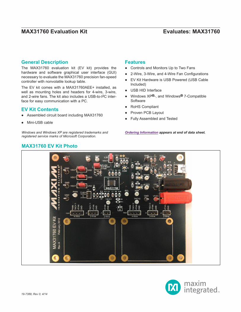
General DescriptionThe MAX31760 evaluation kit (EV kit) provides the hardware and software graphical user interface (GUI) necessary to evaluate the MAX31760 precision fan-speed controller with nonvolatile lookup table. The EV kit comes with a MAX31760AEE+ installed, as well as mounting holes and headers for 4-wire, 3-wire, and 2-wire fans. The kit also includes a USB-to-I2C inter-face for easy communication with a PC.
EV Kit Contents ● Assembled circuit board including MAX31760
● Mini-USB cable
Features ● Controls and Monitors Up to Two Fans ● 2-Wire, 3-Wire, and 4-Wire Fan Configurations ● EV Kit Hardware is USB Powered (USB Cable
Included) ● USB HID Interface ● Windows XP®-, and Windows® 7-Compatible
Software ● RoHS Compliant ● Proven PCB Layout ● Fully Assembled and Tested
19-7389; Rev 0; 4/14
Ordering Information appears at end of data sheet.Windows and Windows XP are registered trademarks and registered service marks of Microsoft Corporation.
Evaluates: MAX31760MAX31760 Evaluation Kit
MAX31760 EV Kit Photo
Maxim Integrated │ 2www.maximintegrated.com
Evaluates: MAX31760MAX31760 Evaluation Kit
Quick StartRequired Equipment
● MAX31760 EV kit hardware ● Windows XP or Windows 7 PC ● Spare USB port ● Mini USB cable (included) ● Power supply to power the fans (the voltage and
current requirements depend on the fans used) ● One or two 2-wire, 3-wire or 4-wire fans (not included)
Note: In the following sections, software-related items are identified by bolding. Text in bold refers to items directly from the install or EV kit software. Text in bold and underlined refers to items from the Windows operating system.
ProcedureThe EV kit is fully assembled and tested. Follow the steps below to verify board operation:1) Ensure that jumpers/shunts J9 and J11 are installed.2) Connect fan(s) to FAN1 or FAN2 for 4-wire fans, J2 or
J4 for 3-wire fans, or J3 or J5 for 2-wire fans.3) If using 3-Wire or 2-Wire fans, ensure that jumper/
shunt J10 is installed.4) Set the EV kit hardware on a nonconductive surface to
ensure that nothing on the PCB gets shorted together.5) Prior to starting the GUI, connect the EV kit hardware
to a PC using the supplied Mini-USB cable, or equiva-lent. The COM LED (D2) should flash between red and orange.
6) Windows should automatically begin installing the necessary device driver. The USB interface of the EV kit hardware is configured as an HID device and therefore does not require a unique/custom device driver. Once the driver installation is complete, a Win-dows message appears near the System Icon menu indicating that the hardware is ready to use. Do not attempt to run the GUI prior to this message. If you do, you must close the application and restart it once the driver installation is complete. On some versions of Windows, administrator privileges may be required to install the USB device.
7) Once the device driver installation is complete, visit www.maximintegrated.com/evkitsoftware to download the latest version of the EV kit software, MAX31760EVKitSetup.zip. Save the EV kit software to a temporary folder.
8) Unzip the .ZIP file and double-click the .EXE file to run the installer. A message box stating: The publisher could not be verified. Are you sure you want to run this software? may appear. If so, click Yes.
9) Follow the instructions on the installer and once complete, click Finish. The default location of the GUI is in the program files directory.
10) When the GUI appears, the EV Kit Status box in the Status section should indicate that the EV kit hard-ware is connected. The COM LED (D2) on the EV kit board should turn green.
11) Connect the fan power supply to VFAN and GND banana connectors and turn on.
12) Click the Read All or Read buttons to read the contents on the associated tab.
Detailed Description of SoftwareStatusIn the Status group box (shown in Figure 1), the EV Kit Status displays Connected if the EV kit hardware is detected. The Auto Read edit box updates to ON when the Start button in the Multiple Reads group box is clicked. The Data Log edit box displays ON when the Log to File checkbox is checked in the Multiple Reads group box. The Slave Address edit box defaults to A0h and can be changed using the Software Slave Address edit box on the User EEPROM and I2C Commands tab. The ALERT, SHDN, and Fan Fail statuses are read from the device pins. The rest of the items in the Status group box are read from registers of the device.
Multiple ReadsThis group box allows the user to enter a desired number of samples, as well as the delay between the samples (in milliseconds), to automate readings. The sample read includes the local temperature, remote temperature, TACH 1 count, TACH 2 count, current duty cycle, Alert, SHDN, Fan Fail, Status register, and the other registers in the Status group box. It is also possible to write the
MAX31760 EV Kit FilesFILE DESCRIPTION
MAX31760EVKitSetup.EXE Application ProgramNote: The .EXE file is downloaded as a .ZIP file.
Maxim Integrated │ 3www.maximintegrated.com
Evaluates: MAX31760MAX31760 Evaluation Kit
results to a file by clicking the Log to File checkbox and providing a folder and filename for the comma-separated value (.csv) file to be stored. The Auto Read and Data Log edit boxes in the Status group box update to ON when the Start button is clicked or when Log to File is checked.
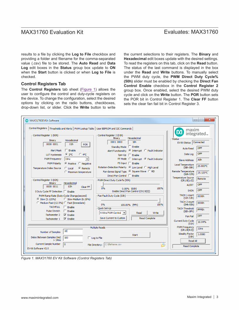
Control Registers TabThe Control Registers tab sheet (Figure 1) allows the user to configure the control and duty-cycle registers on the device. To change the configuration, select the desired options by clicking on the radio buttons, checkboxes, drop-down list, or slider. Click the Write button to write
the current selections to their registers. The Binary and Hexadecimal edit boxes update with the desired settings. To read the registers on this tab, click on the Read button. The status of the last command is displayed in the box under the Read and Write buttons. To manually select the PWM duty cycle, the PWM Direct Duty Cycle% (50h) slider must be enabled by checking the Direct Fan Control Enable checkbox in the Control Register 2 group box. Once enabled, select the desired PWM duty cycle and click on the Write button. The POR button sets the POR bit in Control Register 1. The Clear FF button sets the clear fan fail bit in Control Register 3.
Figure 1. MAX31760 EV Kit Software (Control Registers Tab)
Maxim Integrated │ 4www.maximintegrated.com
Evaluates: MAX31760MAX31760 Evaluation Kit
Quick Set-UpThe Quick Set-Up group box automatically adjusts the settings for 4-wire, 3-wire and 2-wire fans. The 4-wire setup changes the PWM Frequency to 25kHz and enables Tachometer 1 and Tachometer 2 monitor-ing. The 3-wire setup changes the PWM Frequency to 33Hz, enables Direct Fan Control, sets the PWM Direct Duty Cycle to 100%, and enables Tachometer 1 and Tachometer 2 monitoring. The 2-wire setup changes the PWM Frequency to 33Hz and disables Tachometer 1 and Tachometer 2 monitoring. The Save Current to Custom button allows the user to save all the current settings on the Control Registers tab. The custom set-tings can be accessed by selecting the Custom option in
the drop-down list. To activate any of these settings, the Write button must be clicked to write to the registers on the device.
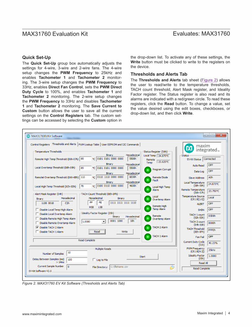
Thresholds and Alerts TabThe Thresholds and Alerts tab sheet (Figure 2) allows the user to read/write to the temperature thresholds, TACH count threshold, Alert Mask register, and Ideality Factor register. The Status register is also read and its alarms are indicated with a red/green circle. To read these registers, click the Read button. To change a value, set the value desired using the edit boxes, checkboxes, or drop-down list, and then click Write.
Figure 2. MAX31760 EV Kit Software (Thresholds and Alerts Tab)
Maxim Integrated │ 5www.maximintegrated.com
Evaluates: MAX31760MAX31760 Evaluation Kit
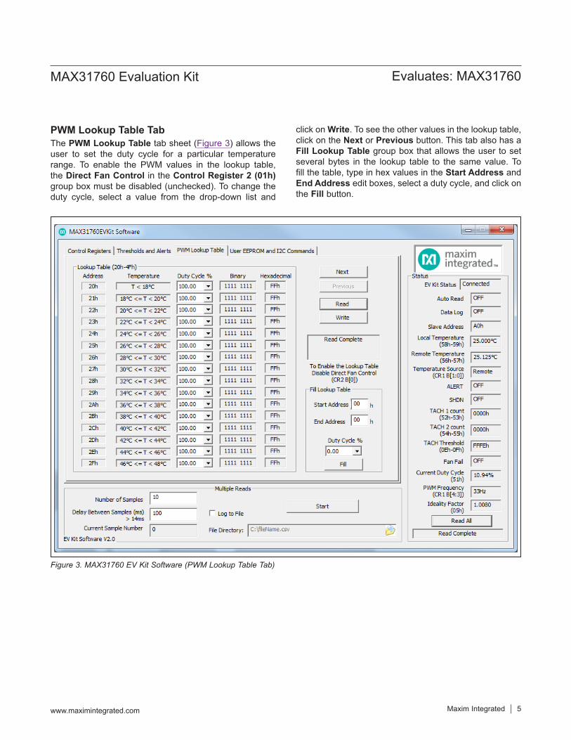
PWM Lookup Table TabThe PWM Lookup Table tab sheet (Figure 3) allows the user to set the duty cycle for a particular temperature range. To enable the PWM values in the lookup table, the Direct Fan Control in the Control Register 2 (01h) group box must be disabled (unchecked). To change the duty cycle, select a value from the drop-down list and
click on Write. To see the other values in the lookup table, click on the Next or Previous button. This tab also has a Fill Lookup Table group box that allows the user to set several bytes in the lookup table to the same value. To fill the table, type in hex values in the Start Address and End Address edit boxes, select a duty cycle, and click on the Fill button.
Figure 3. MAX31760 EV Kit Software (PWM Lookup Table Tab)
Maxim Integrated │ 6www.maximintegrated.com
Evaluates: MAX31760MAX31760 Evaluation Kit
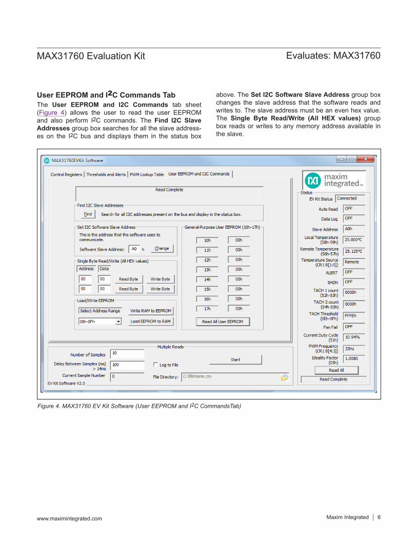
User EEPROM and I2C Commands TabThe User EEPROM and I2C Commands tab sheet (Figure 4) allows the user to read the user EEPROM and also perform I2C commands. The Find I2C Slave Addresses group box searches for all the slave address-es on the I2C bus and displays them in the status box
above. The Set I2C Software Slave Address group box changes the slave address that the software reads and writes to. The slave address must be an even hex value. The Single Byte Read/Write (All HEX values) group box reads or writes to any memory address available in the slave.
Figure 4. MAX31760 EV Kit Software (User EEPROM and I2C CommandsTab)
Maxim Integrated │ 7www.maximintegrated.com
Evaluates: MAX31760MAX31760 Evaluation Kit
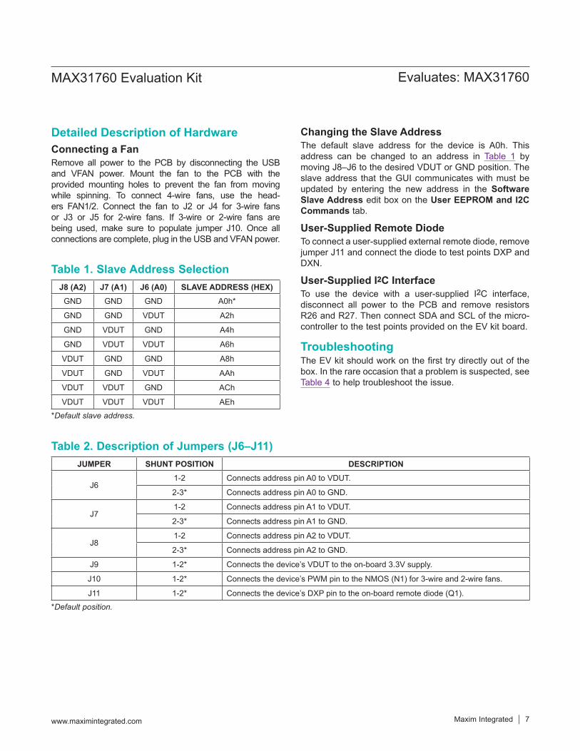
Detailed Description of HardwareConnecting a FanRemove all power to the PCB by disconnecting the USB and VFAN power. Mount the fan to the PCB with the provided mounting holes to prevent the fan from moving while spinning. To connect 4-wire fans, use the head-ers FAN1/2. Connect the fan to J2 or J4 for 3-wire fans or J3 or J5 for 2-wire fans. If 3-wire or 2-wire fans are being used, make sure to populate jumper J10. Once all connections are complete, plug in the USB and VFAN power.
Changing the Slave AddressThe default slave address for the device is A0h. This address can be changed to an address in Table 1 by moving J8–J6 to the desired VDUT or GND position. The slave address that the GUI communicates with must be updated by entering the new address in the Software Slave Address edit box on the User EEPROM and I2C Commands tab.
User-Supplied Remote DiodeTo connect a user-supplied external remote diode, remove jumper J11 and connect the diode to test points DXP and DXN.
User-Supplied I2C InterfaceTo use the device with a user-supplied I2C interface, disconnect all power to the PCB and remove resistors R26 and R27. Then connect SDA and SCL of the micro-controller to the test points provided on the EV kit board.
TroubleshootingThe EV kit should work on the first try directly out of the box. In the rare occasion that a problem is suspected, see Table 4 to help troubleshoot the issue.
Table 1. Slave Address SelectionJ8 (A2) J7 (A1) J6 (A0) SLAVE ADDRESS (HEX)
GND GND GND A0h*
GND GND VDUT A2h
GND VDUT GND A4h
GND VDUT VDUT A6h
VDUT GND GND A8h
VDUT GND VDUT AAh
VDUT VDUT GND ACh
VDUT VDUT VDUT AEh
*Default slave address.
Table 2. Description of Jumpers (J6–J11)JUMPER SHUNT POSITION DESCRIPTION
J61-2 Connects address pin A0 to VDUT.
2-3* Connects address pin A0 to GND.
J71-2 Connects address pin A1 to VDUT.
2-3* Connects address pin A1 to GND.
J81-2 Connects address pin A2 to VDUT.
2-3* Connects address pin A2 to GND.
J9 1-2* Connects the device’s VDUT to the on-board 3.3V supply.
J10 1-2* Connects the device’s PWM pin to the NMOS (N1) for 3-wire and 2-wire fans.
J11 1-2* Connects the device’s DXP pin to the on-board remote diode (Q1).
*Default position.
Maxim Integrated │ 8www.maximintegrated.com
Evaluates: MAX31760MAX31760 Evaluation Kit
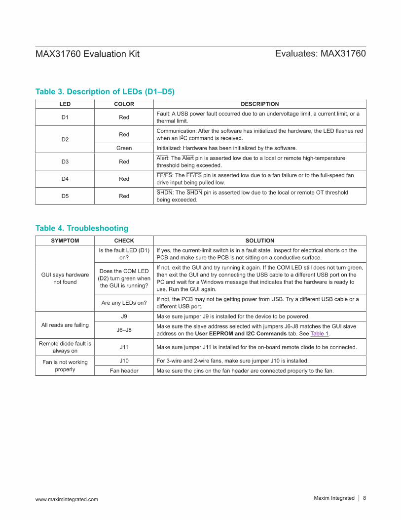
Table 3. Description of LEDs (D1–D5)LED COLOR DESCRIPTION
D1 Red Fault: A USB power fault occurred due to an undervoltage limit, a current limit, or a thermal limit.
D2Red Communication: After the software has initialized the hardware, the LED flashes red
when an I2C command is received.
Green Initialized: Hardware has been initialized by the software.
D3 Red Alert: The Alert pin is asserted low due to a local or remote high-temperature threshold being exceeded.
D4 Red FF/FS: The FF/FS pin is asserted low due to a fan failure or to the full-speed fan drive input being pulled low.
D5 Red SHDN: The SHDN pin is asserted low due to the local or remote OT threshold being exceeded.
Table 4. TroubleshootingSYMPTOM CHECK SOLUTION
GUI says hardware not found
Is the fault LED (D1) on?
If yes, the current-limit switch is in a fault state. Inspect for electrical shorts on the PCB and make sure the PCB is not sitting on a conductive surface.
Does the COM LED (D2) turn green when the GUI is running?
If not, exit the GUI and try running it again. If the COM LED still does not turn green, then exit the GUI and try connecting the USB cable to a different USB port on the PC and wait for a Windows message that indicates that the hardware is ready to use. Run the GUI again.
Are any LEDs on? If not, the PCB may not be getting power from USB. Try a different USB cable or a different USB port.
All reads are failingJ9 Make sure jumper J9 is installed for the device to be powered.
J6–J8 Make sure the slave address selected with jumpers J6-J8 matches the GUI slave address on the User EEPROM and I2C Commands tab. See Table 1.
Remote diode fault is always on J11 Make sure jumper J11 is installed for the on-board remote diode to be connected.
Fan is not working properly
J10 For 3-wire and 2-wire fans, make sure jumper J10 is installed.
Fan header Make sure the pins on the fan header are connected properly to the fan.
Maxim Integrated │ 9www.maximintegrated.com
Evaluates: MAX31760MAX31760 Evaluation Kit
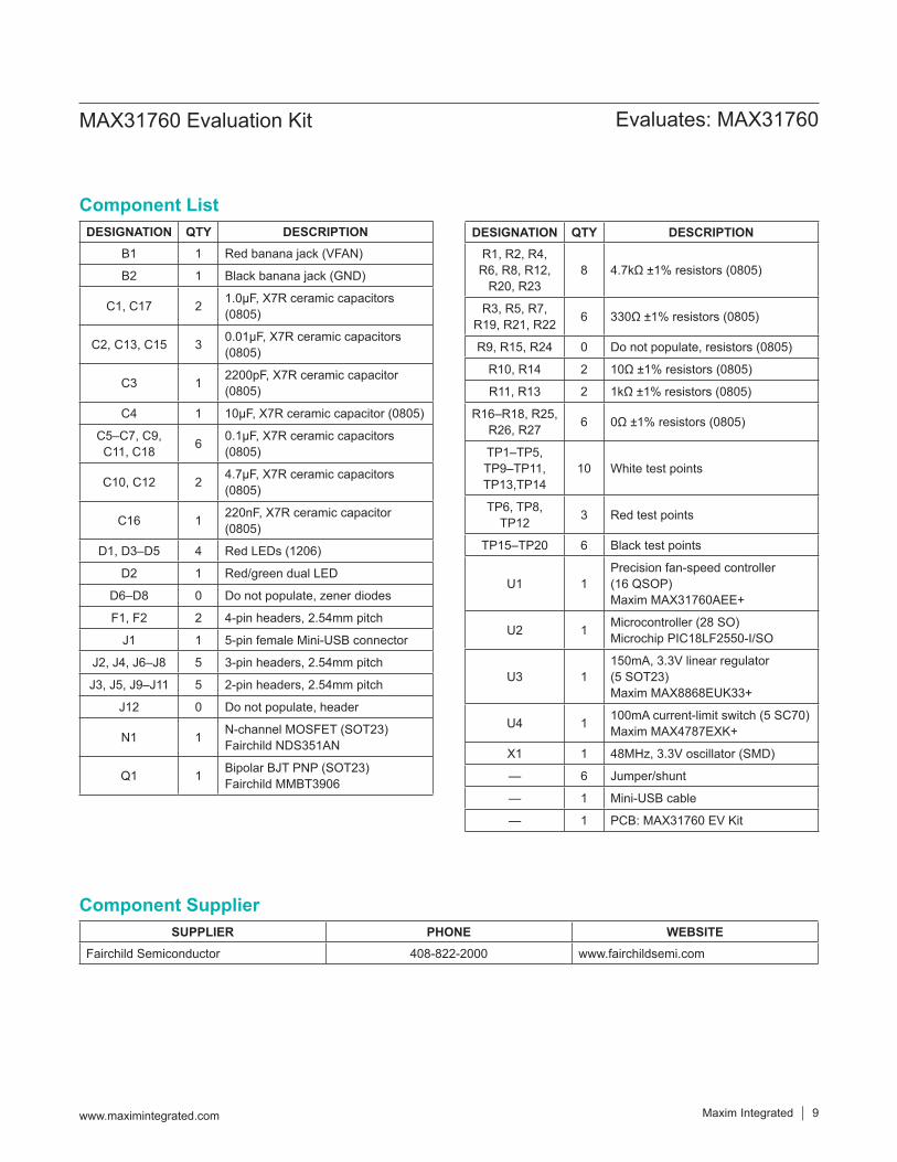
Component ListDESIGNATION QTY DESCRIPTION
B1 1 Red banana jack (VFAN)
B2 1 Black banana jack (GND)
C1, C17 2 1.0μF, X7R ceramic capacitors (0805)
C2, C13, C15 3 0.01μF, X7R ceramic capacitors (0805)
C3 1 2200pF, X7R ceramic capacitor (0805)
C4 1 10μF, X7R ceramic capacitor (0805)
C5–C7, C9, C11, C18 6 0.1μF, X7R ceramic capacitors
(0805)
C10, C12 2 4.7μF, X7R ceramic capacitors (0805)
C16 1 220nF, X7R ceramic capacitor (0805)
D1, D3–D5 4 Red LEDs (1206)
D2 1 Red/green dual LED
D6–D8 0 Do not populate, zener diodes
F1, F2 2 4-pin headers, 2.54mm pitch
J1 1 5-pin female Mini-USB connector
J2, J4, J6–J8 5 3-pin headers, 2.54mm pitch
J3, J5, J9–J11 5 2-pin headers, 2.54mm pitch
J12 0 Do not populate, header
N1 1 N-channel MOSFET (SOT23)Fairchild NDS351AN
Q1 1 Bipolar BJT PNP (SOT23)Fairchild MMBT3906
DESIGNATION QTY DESCRIPTIONR1, R2, R4,
R6, R8, R12, R20, R23
8 4.7kΩ ±1% resistors (0805)
R3, R5, R7, R19, R21, R22 6 330Ω ±1% resistors (0805)
R9, R15, R24 0 Do not populate, resistors (0805)
R10, R14 2 10Ω ±1% resistors (0805)
R11, R13 2 1kΩ ±1% resistors (0805)
R16–R18, R25, R26, R27 6 0Ω ±1% resistors (0805)
TP1–TP5, TP9–TP11, TP13,TP14
10 White test points
TP6, TP8, TP12 3 Red test points
TP15–TP20 6 Black test points
U1 1Precision fan-speed controller (16 QSOP)Maxim MAX31760AEE+
U2 1 Microcontroller (28 SO)Microchip PIC18LF2550-I/SO
U3 1150mA, 3.3V linear regulator (5 SOT23)Maxim MAX8868EUK33+
U4 1 100mA current-limit switch (5 SC70)Maxim MAX4787EXK+
X1 1 48MHz, 3.3V oscillator (SMD)
— 6 Jumper/shunt
— 1 Mini-USB cable
— 1 PCB: MAX31760 EV Kit
Component SupplierSUPPLIER PHONE WEBSITE
Fairchild Semiconductor 408-822-2000 www.fairchildsemi.com
Maxim Integrated │ 10www.maximintegrated.com
Evaluates: MAX31760MAX31760 Evaluation Kit
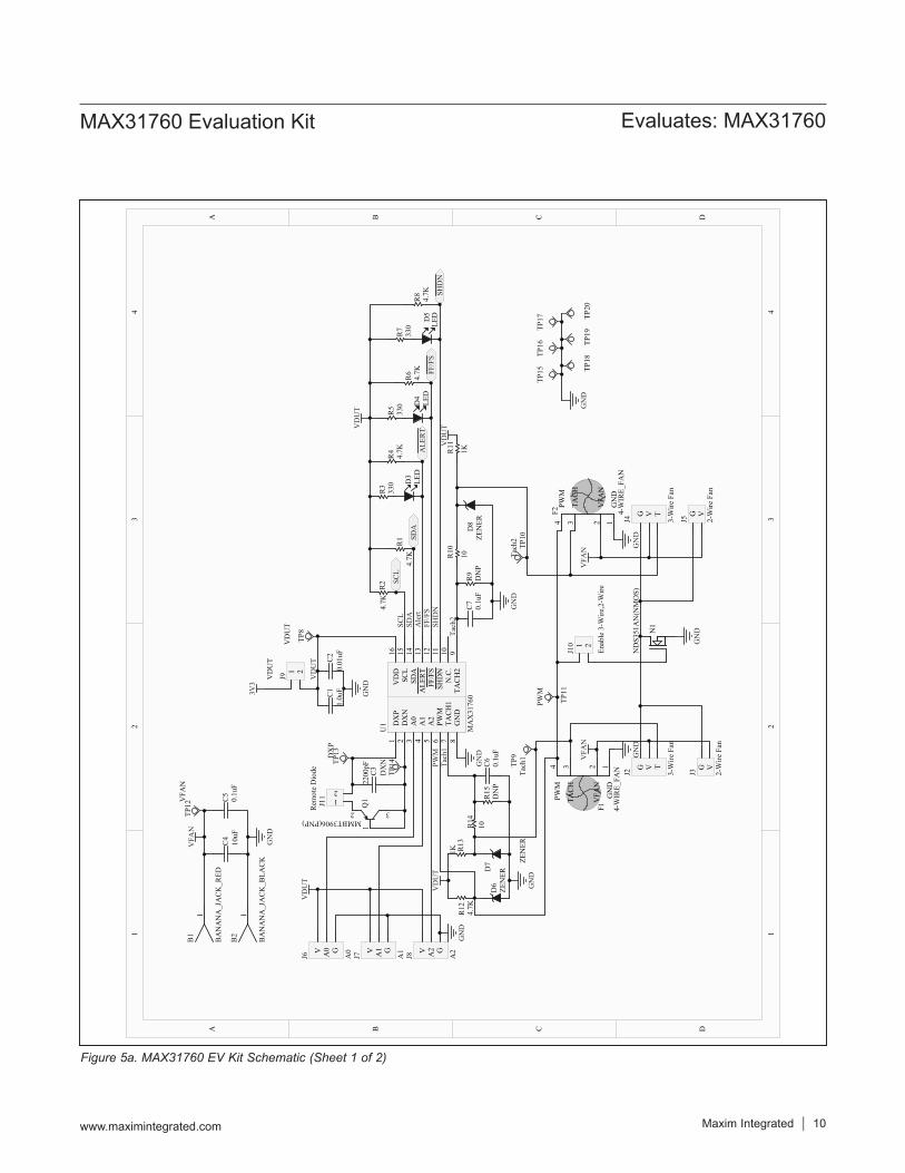
Figure 5a. MAX31760 EV Kit Schematic (Sheet 1 of 2)
11
22
33
44
DD
CC
BB
AA
GND
1VFA
N2
TACH
3PW
M4
F1 4-WIRE_
FAN
GND
1VFA
N2
TACH
3PW
M4
F2 4-WIRE_
FAN
12 3Q
1
MMBT3906(PNP)
C3
2200pF
C1
1.0uF
C2
0.01uF
R12
4.7K
R5
330
R8
4.7K
R3
330
R7
330
R4
4.7K
R6
4.7K
D3
LED
D4
LED
D5
LED
V A0 G
J6 A0 V A1 G
J7 A1 V A2 G
J8 A2
N1
NDS351AN(NMOS)
D7 ZE
NER
D6
ZENER
1B2
BANANA_JACK_B
LACK
1B1
BANANA_JACK_R
ED
SHDN
FF/FS
ALE
RT
SDA
SCL
D8
ZENER
G V T
J2 3-Wire Fan
G V T
J4 3-Wire Fan
G V
J3 2-Wire Fan
G V
J5 2-Wire Fan
PWM
SCL
SDA
Alert
FF/FS
SHDN
Tach1
GND
GND
GND
GND
GND
GND
GND
GND
VDUT
VDUT
3V3
VDUT
VDUT
GND
VFA
N
VFA
NVFA
N
Tach2
C4
10uF
C5
0.1uF
1 2
J9VDUT
R2
4.7K
R1
4.7K
VDUT
R9
DNP
R10
10
R11
1KR13
1K
R14
10R15
DNP
C7
0.1uF
C6
0.1uF
1 2
J10
Enable 3-W
ire,2-W
ire
TP12VFA
N
TP8
VDUT
TP11
PWM
TP10
Tach2
TP9
Tach1
TP15
TP16
TP20
TP19
TP17
TP18
GND
DXP
1
DXN
2
A0
3
A1
4
A2
5
PWM
6
TACH1
7
GND
8TA
CH2
9N.C.
10SH
DN
11FF/FS
12ALE
RT
13SD
A14
SCL
15VDD
16U1
MAX31760
TP13DXP
TP14
DXN
12
J11
Rem
ote Diode
Maxim Integrated │ 11www.maximintegrated.com
Evaluates: MAX31760MAX31760 Evaluation Kit
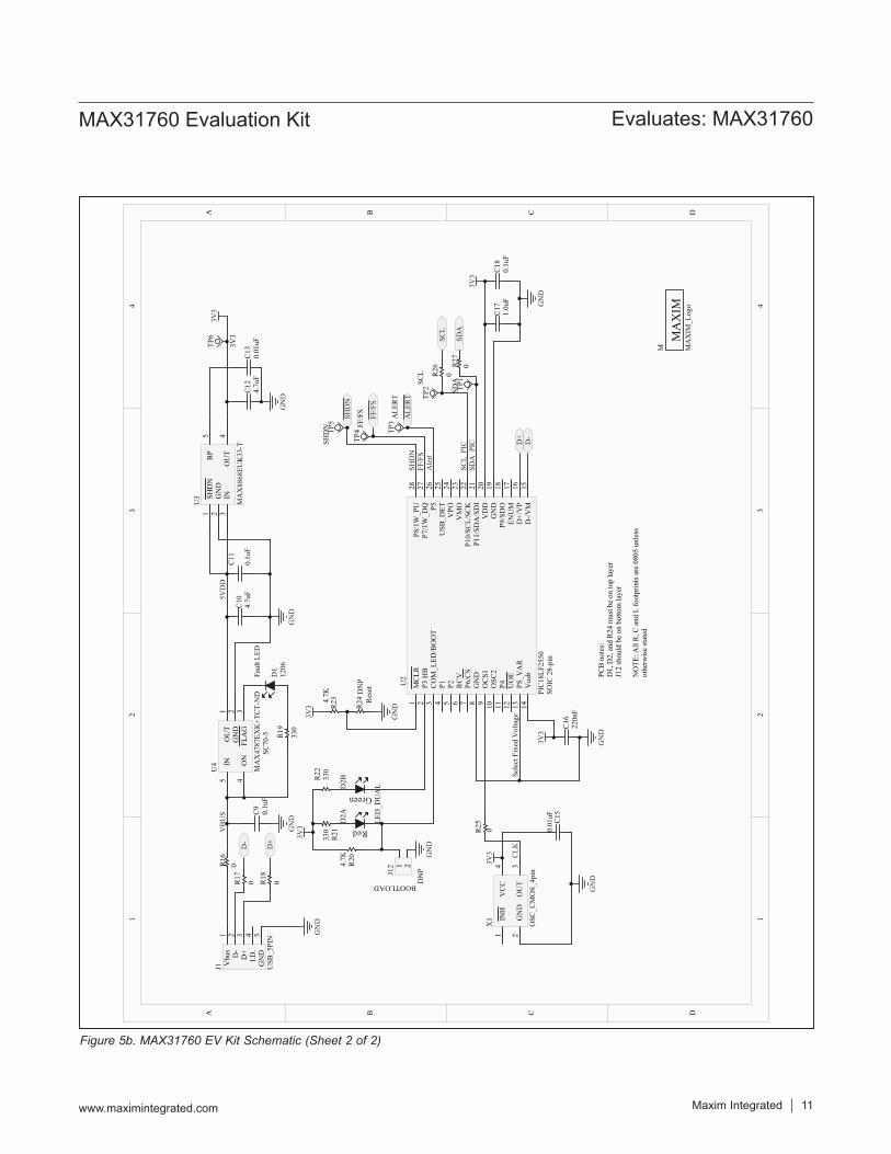
Figure 5b. MAX31760 EV Kit Schematic (Sheet 2 of 2)
11
22
33
44
DD
CC
BB
AA
MCLR
1
P3 HB
2
COM_L
ED/BOOT
3
P14
P25
RCV
6
P6/CS
7
GND
8
OCS1
9
OSC
210
P411
UOE
12
PS_V
AR
13
Vusb
14D-/V
M15
D+/VP
16EN
UM
17P9/SDO
18GND
19VDD
20P11/SD
A/SDI
21P10/SC
L/SC
K22
VMO
23VPO
24USB
_DET
25P5
26P7/1W_D
Q27
P8/1W_PU
28
SOIC 28-pin
U2
PIC18LF
2550
Vbus
1
D-
2
D+
3
I.D.
4
GND
5
J1 USB
_5PIN
MAX4787EX
K+T
CT-ND
OUT
1
GND
2
FLAG
3ON
4
IN5
SC70-5
U4
R16
0R17
0 R18
0
C9
0.1uF
C10
4.7uF
R19
330
1206
D1
Fault L
ED
GND
GND
GND
D+
D-
D-
D+ R
21330 R25 0
R234.7K
C15
0.01uF
GND
GND
VBUS
C11
0.1uF
C12
4.7uF
C13
0.01uF
GND
5VDD
3V3
3V3
NOTE
: All R, C
and L fo
otprints are 0805 unless
otherwise stated
R20
4.7K G
ND
3V3
BOOTLOAD
PCB notes:
D1, D2, and R24 must be on top layer
J12 should be on bottom layer
R24
DNP
GND
Reset
C16
220nF
GND
3V3
Select Fixed Voltage
R22
330
C17
1.0uF
C18
0.1uF
SHDN
1
GND
2
IN3
OUT
4
BP
5U3
MAX8868EU
K33-T
Red
D2A
GreenD2B
LED_D
UAL
INH
1
GND
2OUT
3
VCC
4X1
OSC
_CMOS_4pin
3V3 CLK
SCL
SDA
ALE
RT
FF/FS
SHDN
SHDN
FF/FS
Alert
SCL_
PIC
SDA_PIC
1 2
J12
DNP
R26
0R27
03V
3
TP5
SHDN
TP4FF/FS
TP3ALE
RT TP
2SC
L
TP1
SDA
TP6
3V3 MAXIM
M MAXIM
_Logo
Maxim Integrated │ 12www.maximintegrated.com
Evaluates: MAX31760MAX31760 Evaluation Kit
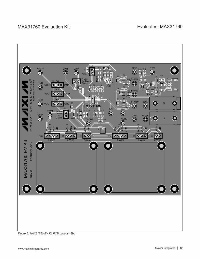
Figure 6. MAX31760 EV Kit PCB Layout—Top
Maxim Integrated │ 13www.maximintegrated.com
Evaluates: MAX31760MAX31760 Evaluation Kit
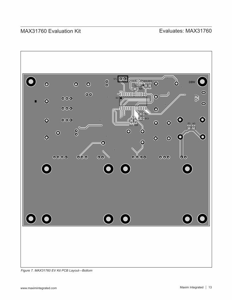
Figure 7. MAX31760 EV Kit PCB Layout—Bottom
Maxim Integrated │ 14www.maximintegrated.com
Evaluates: MAX31760MAX31760 Evaluation Kit
Ordering InformationPART TYPE
MAX31760EVKIT# EV Kit
#Denotes RoHS compliant.
Maxim Integrated cannot assume responsibility for use of any circuitry other than circuitry entirely embodied in a Maxim Integrated product. No circuit patent licenses are implied. Maxim Integrated reserves the right to change the circuitry and specifications without notice at any time.
Maxim Integrated and the Maxim Integrated logo are trademarks of Maxim Integrated Products, Inc. © 2014 Maxim Integrated Products, Inc. │ 15
Evaluates: MAX31760MAX31760 Evaluation Kit
Revision HistoryREVISIONNUMBER
REVISIONDATE DESCRIPTION PAGES
CHANGED0 4/14 Initial release —
For pricing, delivery, and ordering information, please contact Maxim Direct at 1-888-629-4642, or visit Maxim Integrated’s website at www.maximintegrated.com.