Embed Size (px)
Citation preview
MAXIDRIVE3.4+3 WAY STEREO
DIGITAL CROSSOVER
www.altoproaudio.com
Version 1.1 OCTOBER 2007
English
LTOR
User's Manual

CAUTIONRISK OF ELECTRIC SHOCK
DO NOT OPEN
TO REDUCE THE RISK OF ELECTRIC SHOCK
PLEASE DO NOT REMOVE THE COVER OR
THE BACK PANEL OF THIS EQUIPMENT.
THERE ARE NO PARTS NEEDED BY USER
INSIDE THE EQUIPMENT. FOR SERVICE,
PLEASE CONTACT QUALIFIED SERVICE
CENTERS.
WARNINGTo reduce the risk of electric shockand fire, do not expose this equipmentto moisture or rain.
Dispose of this product shouldnot be placed in municipal wasteand should be separate collection.
11.
12.
Move this Equipment only with a cart,stand, tripod, or bracket,specified by themanufacturer, orsold with theEquipment. Whena cart is used, usecaution whenmoving the cart /equipmentcombination toavoid possibleinjury from tip-over.
Permanent hearing loss may be caused byexposure to \ extremely high noise levels.The US. Government's Occupational Safetyand Health Administration (OSHA) hasspecified the permissible exposure to noiselevel.These are shown in the following chart:
According to OSHA, an exposure to high SPL inexcess of these limits may result in the loss ofheat. To avoid the potential damage of heat, it isrecommended that Personnel exposed toequipment capable of generating high SPL usehearing protection while such equipment isunder operation.
This symbol, wherever used, alerts you to thepresence of un-insulated and dangerous voltages
within the product enclosure. These are voltages thatmay be sufficient to constitute the risk of electricshock or death.
This symbol, wherever used, alerts you toimportant operating and maintenance instructions.
Protective Ground TerminalAC mains (Alternating Current)
ON: Denotes the product is turned on.OFF: Denotes the product is turned off.
The apparatus shall be connected to a mainssocket outlet with a protective earthingconnection.
The mains plug or an appliance coupler is usedas the disconnect device, the disconnect deviceshall remain readily operable.
Describes precautions that should be observed toprevent damage to the product.
Read this Manual carefully before operation.
Keep this Manual in a safe place.
Be aware of all warnings reportedwith this symbol.
Keep this Equipment away from water andmoisture.
Clean it only with dry cloth. Do not usesolvent or other chemicals.
Do not damp or cover any cooling opening.Install the equipment only in accordance withthe Manufacturer's instructions.
Power Cords are designed for your safety. Donot remove Ground connections! If the plugdoes not fit your AC outlet, seek advice froma qualified electrician. Protect the powercord and plug from any physical stress toavoid risk of electric shock. Do not placeheavy objects on the power cord. This couldcause electric shock or fire.
Unplug this equipment when unused for longperiods of time or during a storm.
Refer all service to qualified service personnelonly. Do not perform any servicing other thanthose instructions contained within theUser's Manual.
To prevent fire and damage to the product,use only the recommended fuse type asindicated in this manual. Do not short-circuitthe fuse holder. Before replacing the fuse,make sure that the product is OFF anddisconnected from the AC outlet.
1.
2.
3.
4.
5.
6.
7.
8.
9.
10.
Please read.
Hazardous Live Terminal
CAUTION
HOURS X DAY EXAMPLE
864321,510,50,25 or less
SPL
90929597100102105110115
Small gigtrainSubway trainHigh level desktop monitorsClassic music concert
Rock concert
IMPORTANT SAFETY INSTRUCTION
3.1 Front Panel
3.2 Rear Panel
4.1 Configuration of The System
4.2 Adjust The Input Signal
5.1 Preset Menu
5.2 Delay Menu
5.3 Edit Menu
5.4 Utility Menu
1. INTRODUCTION 1..............................................................................................................................
2. FEATURES 1.......................................................................................................................................
3. CONTROL ELEMENTS 1..................................................................................................................
4. GETTING STARTED 3........................................................................................................................
8. TECHNICAL SPECIFICATIONS 37..................................................................................................
9. WARRANTY 38..................................................................................................................................
5. THE MENU MAP CONFIGURATION DESCRIPTION 7..................................................................
6. CONNECTIONS 28..........................................................................................................................
7. APPLICATION 29...............................................................................................................................
7.1 Factory Preset Configuration
7.2 Preset Parameters for Line Array
4.3 First Setup
4.4 System Configuration
4.5 Number of Presets
4.6 Type of Preset
4.7 Name of The Preset
4.8 Preset Modifications
4.9 System Protection
7.3 Hookup
IN THIS MANUAL:
ENTERPREV NEXT
ESC
MODE
CLIP
66
1212
1818
2424
A BINPUT LEVELINPUT LEVEL MUTE
CLIP
66
1212
2424
LIMIT
OUTPUTLEVEL
OUTPUTLEVEL
CLIP
66
1212
2424
LIMIT
CLIP
66
1212
2424
LIMIT
CLIP
66
1212
2424
LIMIT
CLIP
66
1212
2424
LIMIT
CLIP
66
1212
2424
LIMIT
OUTPUTLEVEL
OUTPUTLEVEL
OUTPUTLEVEL
OUTPUTLEVEL
OUTPUTLEVEL
OUTPUTLEVEL
OUTPUTLEVEL
OUTPUTLEVEL
OUTPUTLEVEL
OUTPUTLEVEL
MUTE MUTE MUTEMUTE MUTE MUTE
CARD
3-WAY STEREODIGITAL CROSSOVER
3-WAY STEREODIGITAL CROSSOVER
MAXIDRIVE3.4+
1 2 3 4 5 6
R
LTOEDIT
UTILITY
DELAY
PRESET
1
Front Panel
Mountable in a 19" Rack Unit
Delay lines up to 2.5s for each input and up to 300ms for each output
Stereo digital input in AEX/EBU format
A/D and D/A converters for a 117dB dynamic range
Slot for a memory card for the storage of more presets and an easier upgrade of other units
10 Factory presets, 64 user presets and 128 card presets by large memory capacity
Switching power supply
Remote control
Manufactured under QS9000, VDA6.1 certified management system
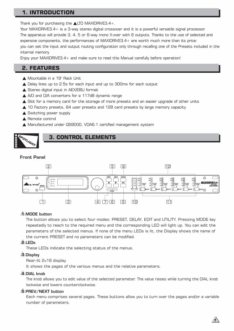
2 LEDs
These LEDs indicate the selecting status of the menus.
Rear-lit 2 16 display.
It shows the pages of the various menus and the relative parameters.
The knob allows you to edit value of the selected parameter. The value raises while turning the DIAL knob
lockwise and lowers counterclockwise.
Thank you for purchasing the LTO MAXIDRIVE3.4+.
Your MAXIDRIVE3.4+ is a 3-way stereo digital crossover and it is a powerful versatile signal processor.
The apparatus will provide 3, 4, 5 or 6-way mono X-over with 6 outputs. Thanks to the use of selected and
expensive components, the performances of MAXIDRIVE3.4+ are worth much more than its price:
you can set the input and output routing configuration only through recalling one of the Presets included in the
internal memory.
Enjoy your MAXIDRIVE3.4+ and make sure to read this Manual carefully before operation!
1 MODE button
The button allows you to select four modes: PRESET, DELAY, EDIT and UTILITY. Pressing MODE key
repeatedly to reach to the required menu and the corresponding LED will light up. You can edit the
parameters of the selected menus. If none of the menu LEDs is lit, the Display shows the name of
the current PRESET and no parameters can be modified.
Each menu comprises several pages. These buttons allow you to turn over the pages and/or a variable
number of parameters.
1. INTRODUCTION
2. FEATURES
SPOTLIG
HT
3. CONTROL ELEMENTS
3 Display
4 DIAL knob
5 PREV/NEXT button
1
2
3 4
5
7 6 9
8
10 11
12
2
SPOTLIG
HT
3. CONTROL ELEMENTS
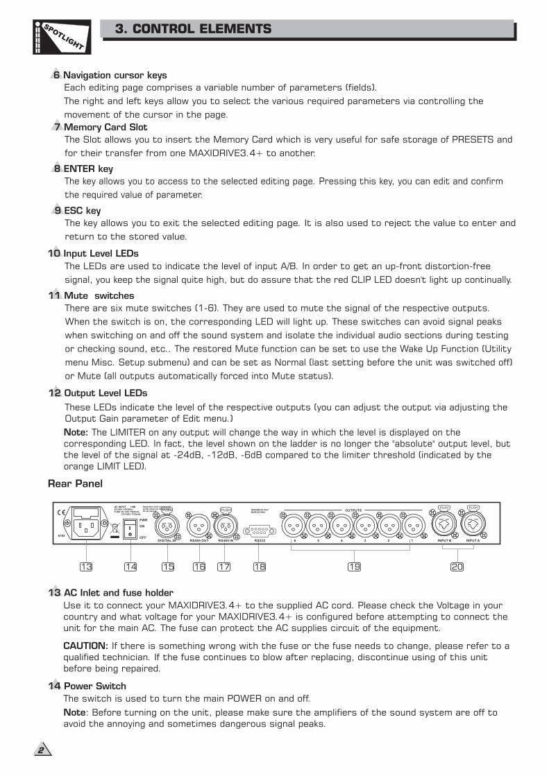
8 ENTER key
The key allows you to access to the selected editing . P ou can edit and confirm
value of parameter.
page ressing this key, y
the required
The LEDs are used to indicate the level of input A/B. In order to get an up-front distortion-free
signal, you keep continually.the signal quite high, but do assure that the red CLIP LED doesn't light up
11 Mute switches
There are six mute switches (1-6). They are used to mute the signal of the respective outputs.
When the switch is on, the corresponding LED will light up. These switches can avoid signal peaks
when switching on and off the sound system and isolate the individual audio sections during testing
or checking sound, etc.. The restored Function (UtilityMute function can be set to use the Wake Up
menu Misc. Setup submenu) and can be set as Normal (last setting before the unit was switched off)
or Mute (all outputs automatically forced into Mute status).
Rear Panel
The Slot allows you to insert the Memory Card which is very useful for safe storage of PRESETS and
for one MAXIDRIVE3.4+ to another.their transfer from
9 ESC key
The key allows you to exit the selected editing page. It is also used to reject the value to enter and
return to the stored value.
12 Output Level LEDs
These LEDs indicate the level of the respective outputs (you can adjust the output via adjusting the
Output Gain parameter of Edit menu.)
Note: The LIMITER on any output will change the way in which the level is displayed on the
corresponding LED. In fact, the level shown on the ladder is no longer the "absolute" output level, but
the level of the signal at -24dB, -12dB, -6dB compared to the limiter threshold (indicated by the
orange LIMIT LED).
13 AC Inlet and fuse holder
14 Power Switch
The switch is used to turn the main POWER on and off.
Note: Before turning on the unit, please make sure the amplifiers of the sound system are off to
avoid the annoying and sometimes dangerous signal peaks.
Use it to connect your MAXIDRIVE3.4+ to the supplied AC cord. Please check the Voltage in your
country and what voltage for your MAXIDRIVE3.4+ is configured before attempting to connect the
unit for the main AC. The fuse can protect the AC supplies circuit of the equipment.
CAUTION: If there is something wrong with the fuse or the fuse needs to change, please refer to a
qualified technician. If the fuse continues to blow after replacing, discontinue using of this unit
before being repaired.
Apparaten skall anslutas tilljordat uttag nar den anslutstill ett natverk
PWR
OFF
ON
AC INPUT 14W95-240V 50/60HzFUSE: 95-120V T500mAL
210-240V T315mAL
DIGITAL IN RS485 OUT RS485 IN RS232 INPUT AINPUT B4 3 2 1
OUTPUTS
56
A102
DESIGNED IN ITALYMADE IN CHINA
PUSH
2 13
NEW TIDE
PUSH
2 13
NEW TIDE
PUSH
1
3
2
NEW TIDE
PUSH
1
3
2
NEW TIDE
7 Memory Card Slot
10 Input Level LEDs
6 Navigation cursor keys
Each editing page comprises a variable number of parameters (fields).
The right and left keys allow you to select the various required parameters via controlling the
movement cursor in the page.of the
13 14 15 16 17 18 19 20
4.1 Configuration of the system
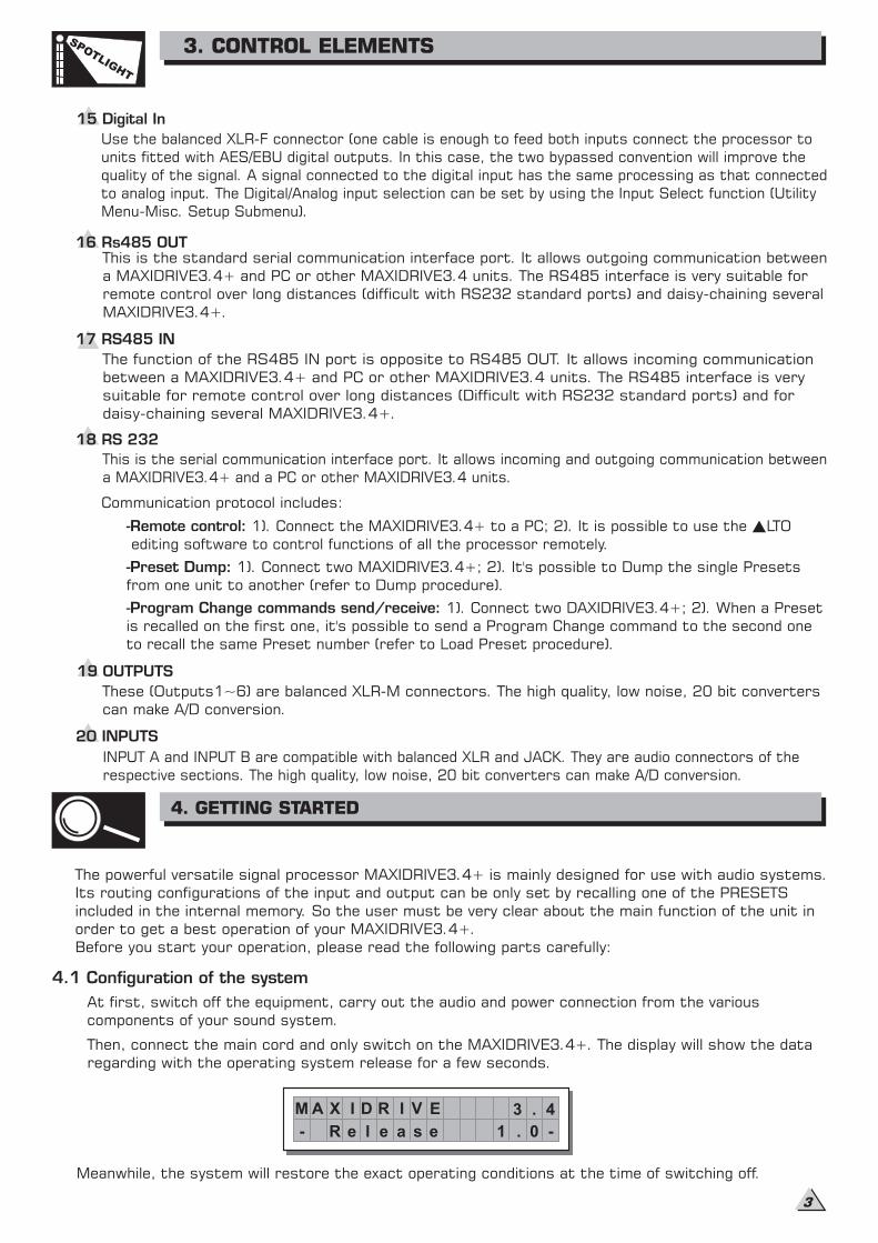
Meanwhile, the system will restore the exact operating conditions at the time of switching off.
16 Rs485 OUTThis is the standard serial communication interface port. It allows outgoing communication between
a MAXIDRIVE3.4+ and PC or other MAXIDRIVE3.4 units. The RS485 interface is very suitable for
remote control over long distances (difficult with RS232 standard ports) and daisy-chaining several
MAXIDRIVE3.4+.
17 RS485 IN
The function of the RS485 IN port is opposite to RS485 OUT. It allows incoming communication
between a MAXIDRIVE3.4+ and PC or other MAXIDRIVE3.4 units. The RS485 interface is very
suitable for remote control over long distances (Difficult with RS232 standard ports) and for
daisy-chaining several MAXIDRIVE3.4+.
18 RS 232
This is the serial communication interface port. It allows incoming and outgoing communication between
a MAXIDRIVE3.4+ and a PC or other MAXIDRIVE3.4 units.
Communication protocol includes:
-Remote control: 1). Connect the MAXIDRIVE3.4+ to a PC; 2). It is possible to use the LTO
editing software to control functions of all the processor remotely.
-Preset Dump: 1). Connect two MAXIDRIVE3.4+; 2). It's possible to Dump the single Presets
from one unit to another (refer to Dump procedure).
-Program Change commands send/receive: 1). Connect two DAXIDRIVE3.4+; 2). When a Preset
is recalled on the first one, it's possible to send a Program Change command to the second one
to recall the same Preset number (refer to Load Preset procedure).
19 OUTPUTS
These (Outputs1~6) are balanced XLR-M connectors. The high quality, low noise, 20 bit converters
can make A/D conversion.
20 INPUTS
INPUT A and INPUT B are compatible with balanced XLR and JACK. They are audio connectors of the
respective sections. The high quality, low noise, 20 bit converters can make A/D conversion.
The powerful versatile signal processor MAXIDRIVE3.4+ is mainly designed for use with audio systems.
Its routing configurations of the input and output can be only set by recalling one of the PRESETS
included in the internal memory. So the user must be very clear about the main function of the unit in
order to get a best operation of your MAXIDRIVE3.4+.
Before you start your operation, please read the following parts carefully:
At first, switch off the equipment, carry out the audio and power connection from the various
components of your sound system.
Then, connect the main cord and only switch on the MAXIDRIVE3.4+. The display will show the data
regarding with the operating system release for a few seconds.
M A X D R I V E 3 . 4
R e l e a s e 1 . 0- -
I
4. GETTING STARTED
SPOTLIG
HT
3. CONTROL ELEMENTS
3
15 Digital In
Use the balanced XLR-F connector (one cable is enough to feed both inputs connect the processor to
units fitted with AES/EBU digital outputs. In this case, the two bypassed convention will improve the
quality of the signal. A signal connected to the digital input has the same processing as that connected
to analog input. The Digital/Analog input selection can be set by using the Input Select function (Utility
Menu-Misc. Setup Submenu).
And the system will enter into default status, showing the main operating information on the display.
Load the containing the you've found.Factory PRESET configuration
Press the Key until the menu LED lights up.MODE PRESET
The display will show the page:Load PRESET
Set all the MAXIDRIVE3.4 outputs in status (LEDs lit) by pressing the relative keys.MUTE
Use the to find the necessary Factory PRESET (indicated by the letter F). Check that if,
among available, there are already some optimised for the specific speaker
enclosures being
DIALthe PRESETS
used.
Press .ENTER
The display shows the PRESET loaded in the units memory and the relative configuration:
Proceed as follows:
Keep the MAXIDRIVE3.4+ outputs in status (LEDs light on).MUTE
Feed a signal in on the MAXIDRIVE3.4+'s input and watch the LED ladders.
make certain the red
INPUT LEVEL A-BTo obtain a good signal/noise ratio, i.e. an up-front distortion-free signal, keep the signal quite high,
but LED doesn't light up continually.CLIP
Adjust the MAXIDRIVE3.4+ input gain if necessary:
Press the key until the menu LED lights up.
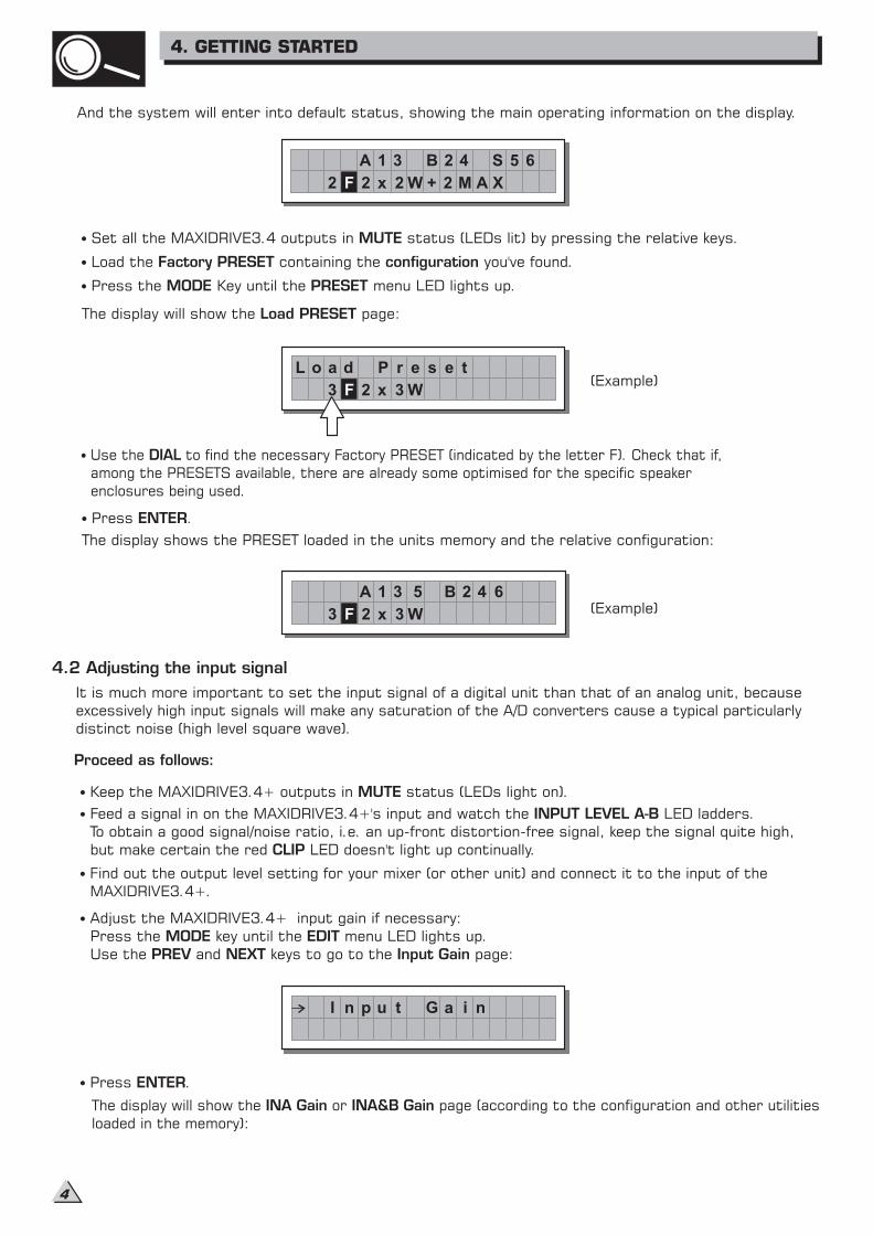
Use the and keys to go to the page:
MODE EDITPREV NEXT Input Gain
It is much more important to set the input signal of a digital unit than that of an analog unit, because
excessively high input signals will make particularlyany saturation of the A/D converters cause a typical
distinct noise (high level square wave).
(Example)
Press .ENTER
The display will show the or page (according to the configuration and other utilitiesINA Gain INA&B Gainloaded in the memory):
A 1 3 B 2 4 S 5 6
2 F 2 x 2 W + 2 M A X
L o a d
3 F 2 x 3 W
P r e s e t
4.2 Adjusting the input signal
A 1 3 B 2 45 6
3 F 2 x 3 W
I n p u t G a i n
Find out the output level setting for your mixer (or other unit) and connect it to the input of the
MAXIDRIVE3.4+.
4. GETTING STARTED
(Example)
4
4.3 First Setup
Disable the MUTE function on the outputs you intend using and listen the sound, carry out
instrumental checks (if you have the necessary equipment) and any corrections required.
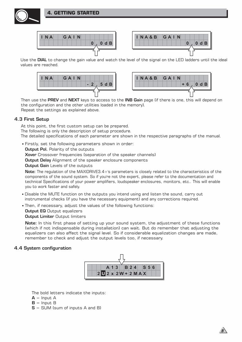
4.4 System configuration
The bold letters indicate the inputs:
= Input A
= Input B
= SUM (sum of inputs A and B)
ABS
2 U 2 x 2 W + 2 M A X
A 1 3 B 2 4 S 5 6
I N A G A I N& B
. 0 d B0
I N A G A I N
. 0 d B0
I N A G A I N
. 5 d B2-
I N A G A I N& B
. 0 d B6+
Firstly, set the following parameters in order:shown
Output Pol. Polarity of the outputs
Xover Crossover frequencies (separation of the speaker channels)
Output Delay Alignment of the speaker enclosure components
Output Gain Levels of the outputs
Then, if necessary, adjust the values of the following functions:
Output EQ Output equalizers
Output Limiter Output limiters
Use the to change the gain value and watch the level of the signal on the LED ladders until the ideal
values are reached.
DIAL
Then use the and keys to access to the page (if there is one, this will depend on
the configuration and the other utilities loaded in the memory).
Repeat the settings as explained above.
PREV NEXT INB Gain
At this point, the first custom setup can be prepared.
The following is only the description of setup procedure.
The detailed specifications of each parameter are shown in the respective paragraphs of the manual.
Note: The regulation of the MAXIDRIVE3.4+'s parameters is closely related to the characteristics of the
components of the sound system. So if you're not the expert, please refer to the documentation and
technical Specifications of your power amplifiers, loudspeaker enclosures, monitors, etc.. This will enable
you to work faster and safely.
Note: In this first phase of setting up your sound system, the adjustment of these functions
(which if not indispensable during installation) can wait. But do remember that adjusting the
equalizers can also affect the signal level. So if considerable equalization changes are made,
remember to check and adjust the output levels too, if necessary.
4. GETTING STARTED
5
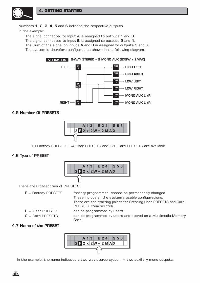
Numbers , , , , and indicate the respective outputs.1 2 3 4 5 6
In the example:
The signal connected to Input is assigned to outputs and .A 1 3
The signal connected to Input is assigned to outputs and .B 2 4
The Sum of the signal on inputs and is assigned to outputs 5 and 6.A B
The system is therefore configured as shown in the following diagram.
A13 B24 S56 2-WAY STEREO + 2 MONO AUX (2X2W + 2MAX)
LEFT
RIGHT
HIGH LEFT
HIGH RIGHT
LOW LEFT
LOW RIGHT
MONO AUX L +R
MONO AUX L +R
INA
INA+B
INB
OUT1
OUT2
OUT3
OUT4
OUT5
OUT6
There are 3 categories of PRESETS:
F = Factory PRESETS factory programmed, cannot be permanently changed.
4.6 Type of PRESET
4.5 Number Of PRESETS
10 Factory PRESETS, 64 User PRESETS and 128 Card PRESETS are available.
F 2 x 2 W + 2 M A X
A 1 3 B 2 4 S 5 6
2
U = User PRESETS can be programmed by users.
C = Card PRESETS can be programmed by users and stored on a Multimedia Memory
Card.
4.7 Name of the PRESET
In the example, the name indicates a two-way stereo system + two auxiliary mono outputs.
F
A 1 3 B 2 4 S 5 6
2 2 x 2 W + 22 M A X
These include all the system's usable configurations.
F 2 x 2 W + 2 M A X
A 1 3 B 2 4 S 5 6
2
These are the starting points for Creating User PRESETS and Card
PRESETS from scratch.
4. GETTING STARTED
6
4.8 PRESET Modifications
4.9 System Protection
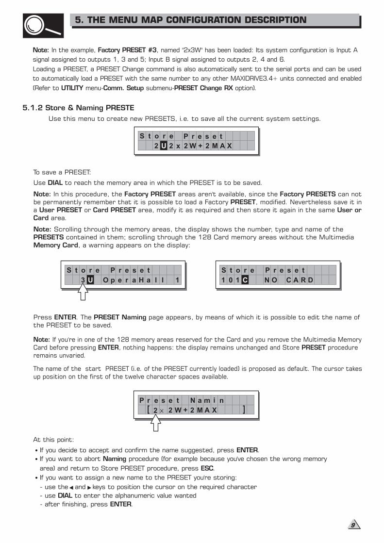
5.1 Preset Menu
Load Preset
Store Preset
Dump Out Preset
Incoming Dump
menu
PRESET
U 2 x 2 W + 2 M A X
A 1 3 B 2 4 S 5 6
2
M
U 2 x 2 W + 2 A X
A 1 3 B 2 4 S 5 6
2
T
U 2 x 2 W + 2 M A X
A 1 3 B 2 4 S 5 6
2
P
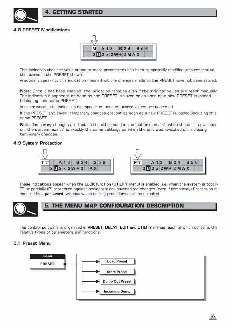
This indicates that the value of one or more parameters has been temporarily modified with respect to
the stored in the PRESET shown.
Practically speaking, this indication means that the changes made to the PRESET have not been stored.
Note: Once it has been enabled, the indication remains even if the "original" values are reset manually.
The indication disappears as soon as the PRESET is saved or as soon as a new PRESET is loaded
(including this same PRESET).
In other words, the indication disappears as soon as stored values are accessed.
If the PRESET isn't saved, temporary changes are lost as soon as a new PRESET is loaded (including this
same PRESET).
Note: Temporary changes are kept on the other hand in the "buffer memory": when the unit is switched
on, the system maintains exactly the same settings as when the unit was switched off, including
temporary changes.
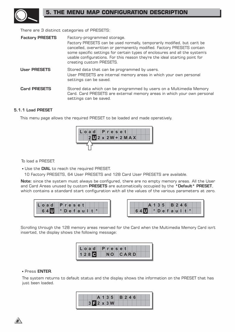
These indications appear when the function ( menu) is enabled, i.e. when the system is totallyLOCK UTILITY( ) or partially ( ) protected against accidental or unauthorized changes (even if temporary).Protection isT Pensured by a , without which editing procedure can't be unlocked.password
The control software is organized in , , and menus, each of which contains thePRESET DELAY EDIT UTILITYrelative types of parameters and functions.
4. GETTING STARTED
5. THE MENU MAP CONFIGURATION DESCRIPTION
7
There are 3 distinct categories of PRESETS:
User PRESETS
Card PRESETS
5.1.1 Load PRESET
This menu page allows the required PRESET to be loaded and made operatively.
To load a PRESET:
Use the to reach the required PRESET.DIAL
10 Factory PRESETS, 64 User PRESETS and 128 Card User PRESETS are available.
Press .ENTER
Factory PRESETS
L o a d
2 U 2 x 2 W
P r e s e t
+ 2 M A X
L o a d
U
P r e s e t
6 4 * D e f a u l t *
A 1 3 5
U6 4 * D e f a u l t *
B 2 4 6
L o a d
C
P r e s e t
1 2 8 N O C A R D
A 1 3 5
F3
B 2 4 6
2 x 3 W
Scrolling through the 128 memory areas reserved for the Card when the Multimedia Memory Card isn't
inserted, the display shows the following message:
Factory-programmed storage.
Factory PRESETS can be used normally, temporarily modified, but can't be
cancelled, overwritten or permanently modified. Factory PRESETS contain
some specific settings for certain types of enclosures and all the system's
usable configurations. For this reason they're the ideal starting point for
creating custom PRESETS.
Stored data that can be programmed by users.
User PRESETS are internal memory areas in which your own personal
settings can be saved.
Stored data which can be programmed by users on a Multimedia Memory
Card. Card PRESETS are external memory areas in which your own personal
settings can be saved.
Note:PRESETS *Default* PRESET
since the system must always be configured, there are no empty memory areas. All the User
and Card Areas unused by custom are automatically occupied by the ,
which contains a standard start configuration with all the values of the various parameters at zero.
The system returns to default status and the display shows the information on the PRESET that has
just been loaded.
5. THE MENU MAP CONFIGURATION DESCRIPTION
8
5.1.2 Store & Naming PRESTE
Use this menu to create new PRESETS, i.e. to save all the current system settings.
To save a PRESET:
Press . The page appears, by means of which it is possible to edit the name of
the PRESET to be saved.
ENTER PRESET Naming
The name of the start PRESET (i.e. of the PRESET currently loaded) is proposed as default. The cursor takes
up position on the first of the twelve character spaces available.
At this point:
If you decide to accept and confirm the name suggested, press .ENTER
If you want to abort procedure (for example because you've chosen the wrong memory
area) and return to Store PRESET procedure, press .
Naming
ESC
If you want to assign a new name to the PRESET you're storing:
- use the and keys to position the cursor on the required character
- use to enter the alphanumeric value wantedDIAL
- after finishing, press .ENTER
S t o r e
2 U 2 x 2 W
P r e s e t
+ 2 M A X
S t o r e
3 U O p e
P r e s e t
r a H a l l 1
S t o r e
1 C N
P r e s e t
01 O C A R D
P r e s m ni
2
N ae t
2 W + 2 M A X
Note:ENTER PRESET
If you're in one of the 128 memory areas reserved for the Card and you remove the Multimedia Memory
Card before pressing , nothing happens: the display remains unchanged and Store procedure
remains unvaried.
Note: Factory PRESET #3In the example, , named "2x3W" has been loaded: Its system configuration is Input A
signal assigned to outputs 1, 3 and 5; Input B signal assigned to outputs 2, 4 and 6.
Loading a PRESET, a PRESET Change command is also automatically sent to the serial ports and can be used
to automatically load a PRESET with the same number to any other MAXIDRIVE3.4+ units connected and enabled
(Refer to menu- submenu- option).UTILITY Comm. Setup PRESET Change RX
Use to reach the memory area in which the PRESET is to be saved.DIAL
Note: Factory PRESET Factory PRESETSIn this procedure, the areas aren't available, since the can not
be permanently remember that it is possible to load a Factory , modified. Nevertheless save it inPRESETa or area, modify it as required and then store it again in the sameUser PRESET Card PRESET User orCard area.
Note:PRESETSMemory Card
Scrolling through the memory areas, the display shows the number, type and name of the
contained in them; scrolling through the 128 Card memory areas without the Multimedia
, a warning appears on the display:
5. THE MENU MAP CONFIGURATION DESCRIPTION
9
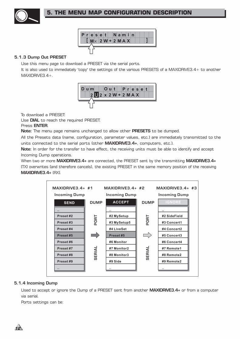
5.1.3 Dump Out PRESET
To download a PRESET:
Use to reach the required PRESET.DIAL
Press .ENTER
Note: PRESETSThe menu page remains unchanged to allow other to be dumped.
All the Presets data (name, configuration, parameter values, etc.) are immediately transmitted to the
units connected to the serial ports (other , computers, etc.).MAXIDRIVE3.4+
Note: In order for the transfer to have effect, the receiving units must be able to identify and accept
Incoming Dump operations.
5.1.4 Incoming Dump
SEND ACCEPT IGNORE
..
Preset #2
Preset #3
Preset #4
Preset #5
Preset #6
Preset #7
Preset #8
Preset #9
..
#2 MySetup
#3 MySetup5
#4 LiveSet
Preset #5
#6 Monitor
#7 Monitor2
#8 Monitor3
#9 Side
..
..
#2 SideField
#3 Concert1
#4 Concert2
#5 Concert3
#6 Concert4
#7 Remote1
#8 Remote2
#9 Remote2
..
Incoming Dump
MAXIDRIVE3.4+ #2
Incoming Dump
MAXIDRIVE3.4+ #1
Incoming Dump
MAXIDRIVE3.4+ #3
SER
IAL
PO
RT
DUMP
SER
IAL
PO
RT
DUMP
..
P r e s m ni
M
N ae t
2 W + 2 M A X
D u m t
2 x
O u
2 W + 2 M A X
P r e s e t
2 U
Use this menu page to download a PRESET via the serial ports.
It is also used to immediately "copy" the settings of the various PRESETS of a MAXIDRIVE3.4+ to another
MAXIDRIVE3.4+.
When two or more are connected, the PRESET sent by the transmittingMAXIDRIVE3.4+ MAXIDRIVE3.4+
(TX) overwrites (and therefore cancels), the existing PRESET in the same memory position of the receiving
MAXIDRIVE3.4+ (RX).
Used to accept or ignore the Dump of a PRESET sent from another or from a computerMAXIDRIVE3.4+
via serial.
Ports settings can be:
5. THE MENU MAP CONFIGURATION DESCRIPTION
10
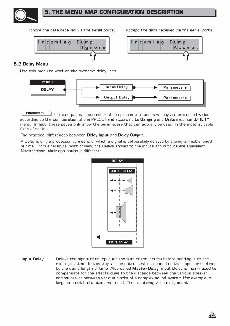
5.2.Delay Menu
Use this menu to work on the systems delay lines.
The practical differences between andDelay Input Delay Output.
A Delay is only a processor by means of which a signal is deliberately delayed by a programmable length
From a technical point of view, the Delays applied to the inputs and outputs are equivalent.
Nevertheless, their application is different:
of time.
In these pages, the number of the parameters and how they are presented varies
according to the configuration of the PRESET and according to and settings (
pages only show the parameters that can actually be used, in the most suitablemenu). In fact, these
form of editing.
Ganging Units UTILITY
Parameters
Input Delay Delays
In this way, all the outputs which depend on that input are delayed
by the Also called , input Delay is mainly used to
compensate for the effects the distance between the various speaker
enclosures or between various
the signal of an input (or the sum of the inputs) before sending it to the
routing system.
same length of time.
dues to
blocks of a complex sound system (for example in
large concert halls, stadiums, etc.), Thus achieving virtual alignment.
Master Delay
Input Delay
Output Delay
Parameters
menu
DELAY
Parameters
Ignore the data received via the serial ports. Accept the data received via the serial ports.
INPUT DELAY
OUTPUT DELAY
DELAY
I n c o m i n g D u m p
n o r eI g
I n c o m i n g D u m p
c e p tA c
5. THE MENU MAP CONFIGURATION DESCRIPTION
11
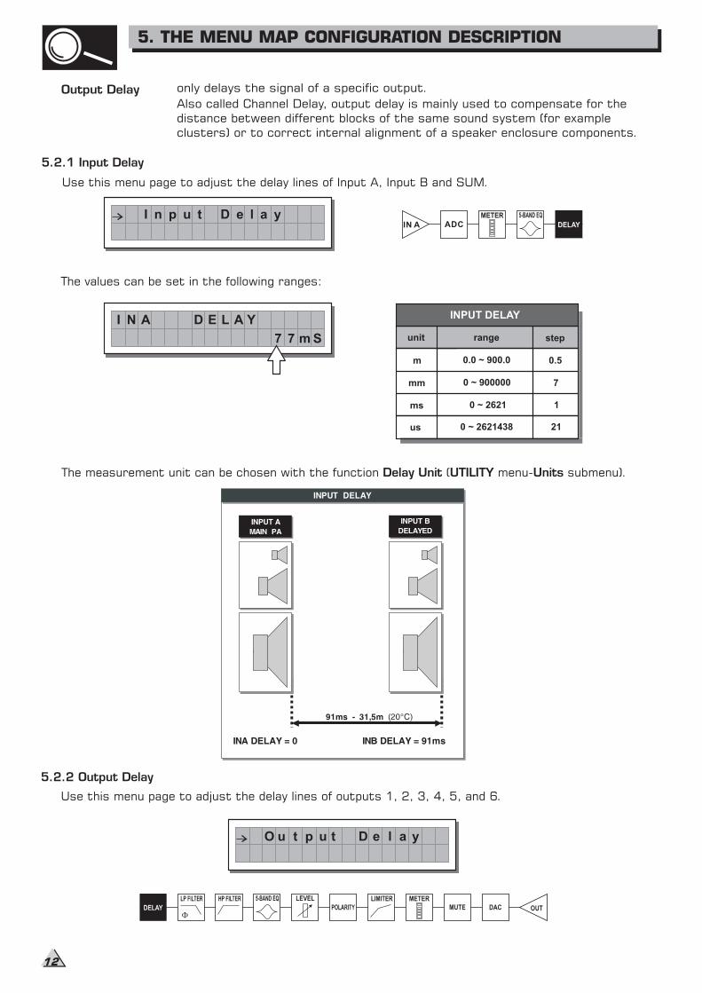
Output Delay only delays the signal of a specific output.
Also called Channel Delay, output delay is mainly used to compensate for the
between different blocks of the same sound system (for example
internal alignment of a speaker enclosure components.
distance
clusters) or to correct
5.2.1 Input Delay
Use this menu page to adjust the delay lines of Input A, Input B and SUM.
The values can be set in the following ranges:
The measurement unit can be chosen with the function ( menu- submenu).Delay Unit UTILITY Units
5.2.2 Output Delay
Use this menu page to adjust the delay lines of outputs 1, 2, 3, 4, 5, and 6.
IN A ADC
unit
m
mm
ms
range step
0.0 ~ 900.0 0.5
0 ~ 900000 7
0 ~ 2621 1
INPUT DELAY
us 0 ~ 2621438 21
I n p u t D e l a y
I N A D E L A Y
7 7 m S
O u t p u t D e l a y
5. THE MENU MAP CONFIGURATION DESCRIPTION
12
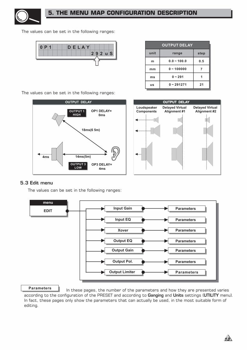
The values can be set in the following ranges:
The values can be set in the following ranges:
5.3 Edit menu
The values can be set in the following ranges:
menu
EDITInput Gain
Input EQ
Xover
Output EQ
Output Gain
Output Pol.
Output Limiter
Parameters
Parameters
Parameters
Parameters
Parameters
Parameters
Parameters
In these pages, the number of the parameters and how they are presented varies
according to the configuration of the PRESET and according to and settings ( menu).Ganging Units UTILITYIn fact, these pages only show the parameters that can actually be used, in the most suitable form of
editing.
Parameters
unit
m
mm
ms
range step
0.0 ~ 100.0 0.5
0 ~ 100000 7
0 ~ 291 1
OUTPUT DELAY
us 0 ~ 291271 21
OUTPUT DELAY
ComponentsLoudspeaker
Alignment #1Delayed Virtual
Alignment #2Delayed Virtual
OUTPUT DELAY
OUTPUT 1
HIGH
OUTPUT DELAY
OP1 DELAY=
0ms
18ms(6 5m)
14ms(5m)
OP3 DELAY=
4ms
OUTPUT 3
LOW
4ms
0 P 1 D E L A Y
2 9 2 u S
5. THE MENU MAP CONFIGURATION DESCRIPTION
13

Threshold
Allows to set the threshold level: if the signal goes below this threshold the Noise Gate reduces
the level. The editing values are within the following ranges: +8dBu -60dBu, with 2dBu steps.
Allows to adjust the amplification of the signal fed in through Inputs A and B.
Editing values are in the range ~ , with steps.+6dB -30dB 0.5dB
I n p u t G a i n
I N A G A I N
- 2 . 5 d B
5.3.2 Input Noise Gate
N o i s e G a t e
Note
INPUT LEVEL A-BCLIP
: Setting the input signal of a digital unit is particularly important, much more than on an
analog unit, as any saturation of the A/D converter due to an excessively high input signal causes
a typical particularly distinct noise. To achieve a good signal/noise ratio, i.e. an up-front distortion
free signal, feed a signal in on the MAXIDRIVE3.4+'s input and watch the LED
ladders. Keep the signal quite high, but make certain the red LED doesn't light on continually.
Noise reduction filter on the inputs
Allows to cut or reduce the background noise generated by the unit connected to the
processor's inputs (the mixer, for example). The filter is active when the input signal is below
a certain threshold and reduce its level cutting the undesired background noises.
The following editable parameters are available, in two different pages:
a. Noise Gate ON/OFF
b. Reaction times
Allows to set the Noise Gate attack and release times.
- ATTACK (AT): is the time needed by the filter to bring back the signal to its normal level when
it goes above the threshold.
- RELEASE (RL): is the time needed by the filter to cut the signal once it goes below the
threshold.
I N A G a t e
5. 0
nO
1 .T 0A ms R L S0
I N A G a t e
5. 0
nO
1 .T 0A ms R L S0
The editing values are within the following ranges: 0dBu -80dBu, with variable steps.
Rage
Allows to set the amount of the signal level reduction.
I N A G a t e
08 0
nO
R -H -T 0 . R G6 0 .
5. THE MENU MAP CONFIGURATION DESCRIPTION
14
5.3.1 Input Gain
Input gain control.
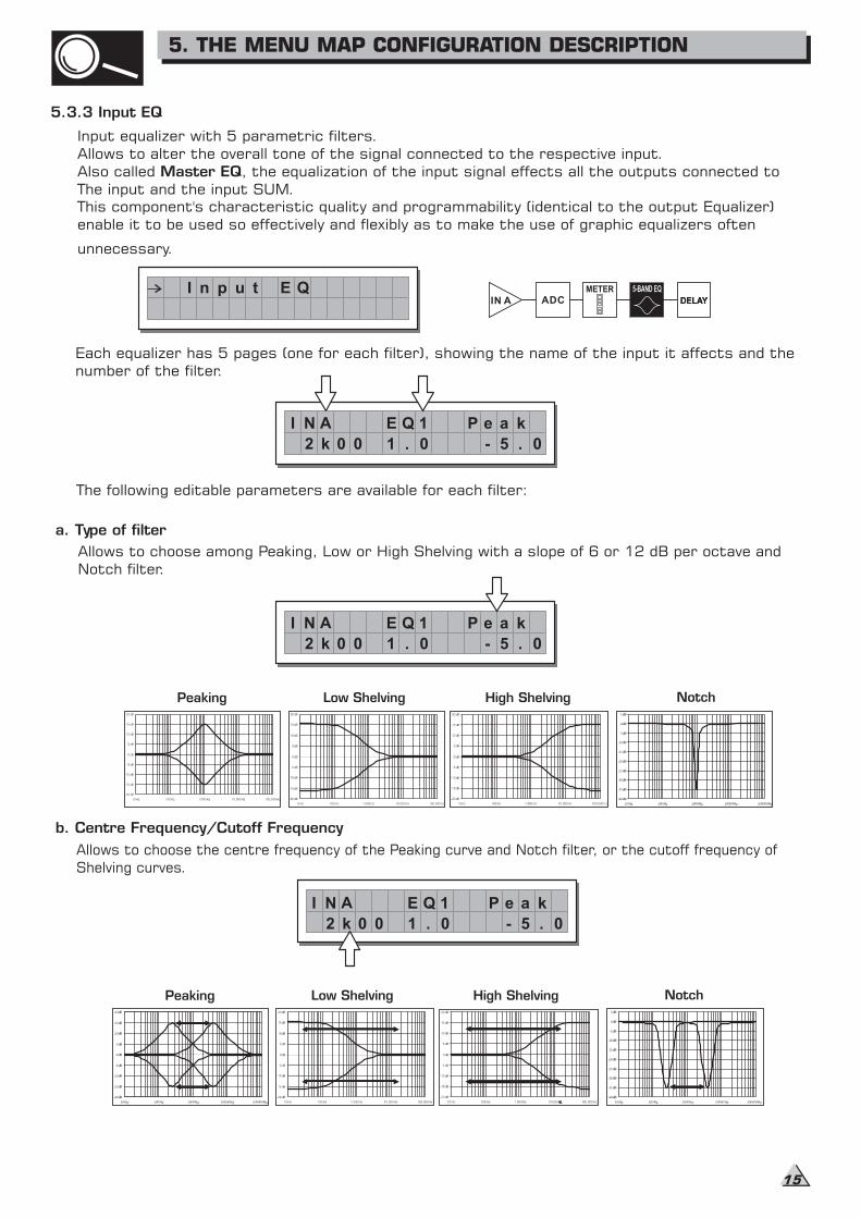
Input equalizer with 5 parametric filters.
Allows to alter the overall tone of the signal connected to the respective input.
Also called , the equalization of the input signal effects all the outputs connected toMaster EQThe input and the input SUM.
This component's characteristic quality and programmability (identical to the output Equalizer)
enable it to be used so effectively and flexibly as to make the use of graphic equalizers often
unnecessary.
Each equalizer has 5 pages (one for each filter), showing the name of the input it affects and the
number of the filter.
The following editable parameters are available for each filter:
Allows to choose among Peaking, Low or High Shelving with a slope of 6 or 12 dB per octave and
Notch filter.
a. Type of filter
Peaking Low Shelving High Shelving Notch
IN A ADCIN A ADCI n p u t E Q
I N A E Q 1
- 5 . 0
kaeP
1 . 02 k 00
I N A E Q 1
- 5 . 0
kaeP
1 . 02 k 00
b. Centre Frequency/Cutoff Frequency
Peaking Low Shelving High Shelving Notch
I N A E Q 1
- 5 . 0
kaeP
1 . 02 k 00
Allows to choose the centre frequency of the Peaking curve and Notch filter, or the cutoff frequency of
Shelving curves.
5.3.3 Input EQ
5. THE MENU MAP CONFIGURATION DESCRIPTION
15
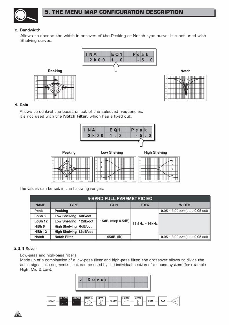
The values can be set in the following ranges:
5.3.4 Xover
Low-pass and high-pass filters.
Made up of a combination of a low-pass filter and high-pass filter, the crossover allows to divide the
into segments that can be used by the individual section of a sound system (for exampleaudio signal
High, Mid & Low).
X o v e r
~
~
~
c. Bandwidth
Allows to choose the width in octaves of the Peaking or Notch type curve. It s not used with
Shelving curves.
Peaking Notch
d. Gain
Allows to control the boost or cut of the selected frequencies.
It's not used with the , which has a fixed cut.Notch Filter
Peaking Low Shelving High Shelving
I N A E Q 1
- 5 . 0
kaeP
1 . 02 k 00
I N A E Q 1
- 5 . 0
kaeP
1 . 02 k 00
5. THE MENU MAP CONFIGURATION DESCRIPTION
16
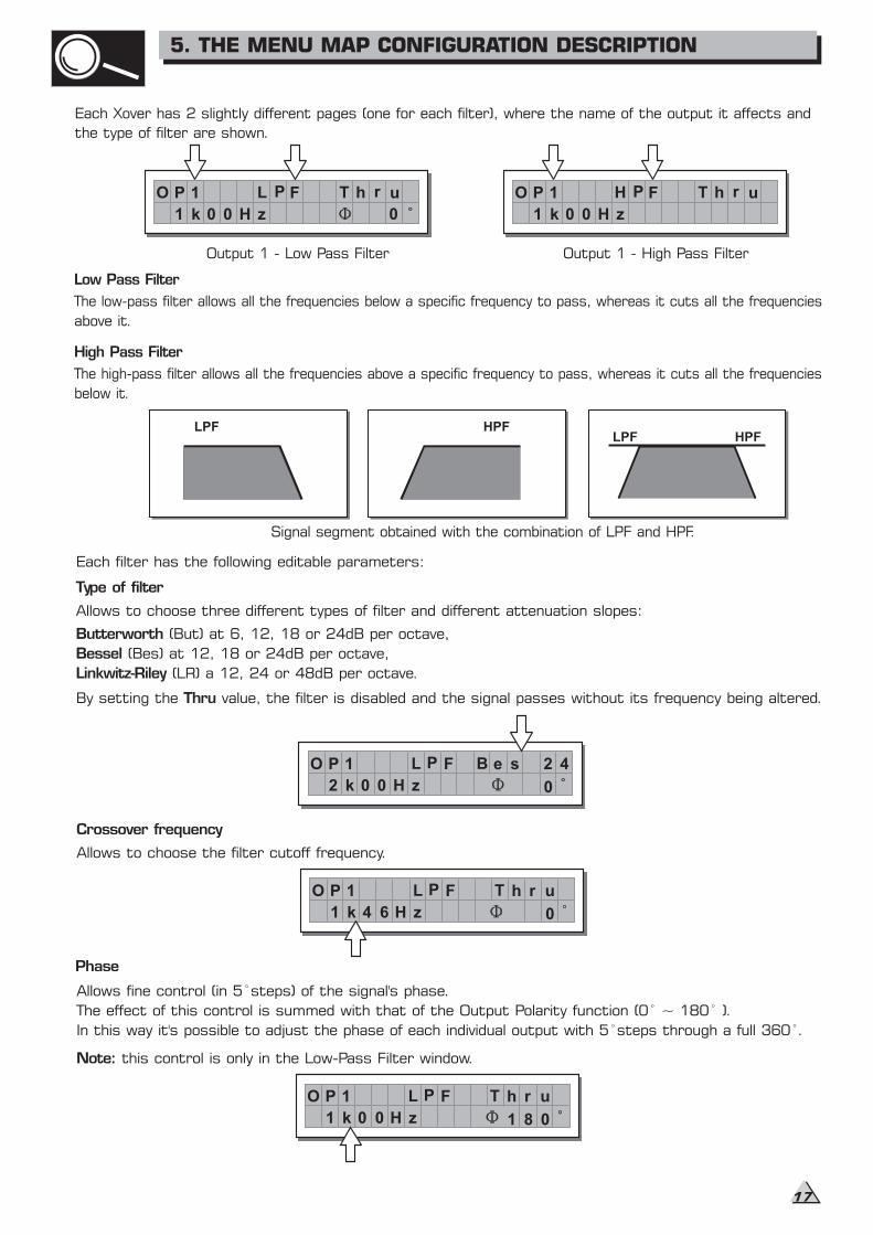
Each filter has the following editable parameters:
Type of filter
Allows to choose three different types of filter and different attenuation slopes:
Butterworth (But) at 6, 12, 18 or 24dB per octave,
Bessel (Bes) at 12, 18 or 24dB per octave,
Linkwitz-Riley (LR) a 12, 24 or 48dB per octave.
By setting the value, the filter is disabled and the signal passes without its frequency being altered.Thru
Crossover frequency
Allows to choose the filter cutoff frequency.
Phase
Allows fine control (in 5 steps) of the signal's phase.
The effect of this control is summed with that of the Output Polarity function (0 ~ 180 ).
In this way it's possible to adjust the phase of each individual output with 5 steps through a full 360 .
Note: this control is only in the Low-Pass Filter window.
O P 1 L P F
2 k 0 0 zH
B e s
0
2 4
O P 1 L P F
1 k 4 6 zH
T h r
0
u
Each Xover has 2 slightly different pages (one for each filter), where the name of the output it affects and
the type of filter are shown.
Low Pass Filter
High Pass Filter
The high-pass filter allows all the frequencies above a specific frequency to pass, whereas it cuts all the frequencies
below it.
LPF HPFHPFLPF
Signal segment obtained with the combination of LPF and HPF.
Output 1 - Low Pass Filter
PO 1
0
L P F h r uT
1 k 0 0 H z
Output 1 - High Pass Filter
O P 1 H P F h r uT
1 k 0 0 H z
The low-pass filter allows all the frequencies below a specific frequency to pass, whereas it cuts all the frequencies
above it.
O P 1 L P F
1 k 0 0 zH
T h r
0
u
81
5. THE MENU MAP CONFIGURATION DESCRIPTION
17
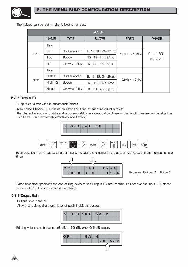
5.3.5 Output EQ
Output equalizer with 5 parametric filters.
Also called Channel EQ, allows to alter the tone of each individual output.
The characteristics of quality and programmability are identical to those of the Input Equalizer and
sed extremely effectively and flexibly.
enable this
unit to be u
Each equalizer has 5 pages (one per filter), indicating the name of the output it effects and the number of the
filter.
Since technical specifications and editing fields of the Output EQ are identical to those of the Input EQ, please
refer to INPUT EQ section for descriptions.
Example: Output 1 - Filter 1
5.3.6 Output Gain
Output level control
Allows to adjust the signal level of each individual output.
Editing values are between +6 dB ~ -30 dB, with 0.5 dB steps.
O u t p u t E Q
O P 1
+ 1 . 5
E Q 1 e a kP
2 k 0 0 1 . 0
O u t p u t G a i n
O P 1
- 6 . 5
G A I N
d B
The values can be set in the following ranges:
NAME TYPE SLOPE FREQ PHASE
XOVER
Thru
But
Bes
LR
Butterworth
Bessel
Linkwitz-Riley
6, 12, 18, 24 dB/oct
12, 18, 24 dB/oct
12, 24, 48 dB/oct
Thru
Hish 6
Hish 12
Notch
Butterworth
Bessel
Linkwitz-Riley
6, 12, 18, 24 dB/oct
12, 18, 24 dB/oct
12, 24, 48 dB/oct
15.6Hz ~ 16KHz
15.6Hz ~ 16KHz
0 ~ 180
(Stp 5 )
LPF
HPF
5. THE MENU MAP CONFIGURATION DESCRIPTION
18
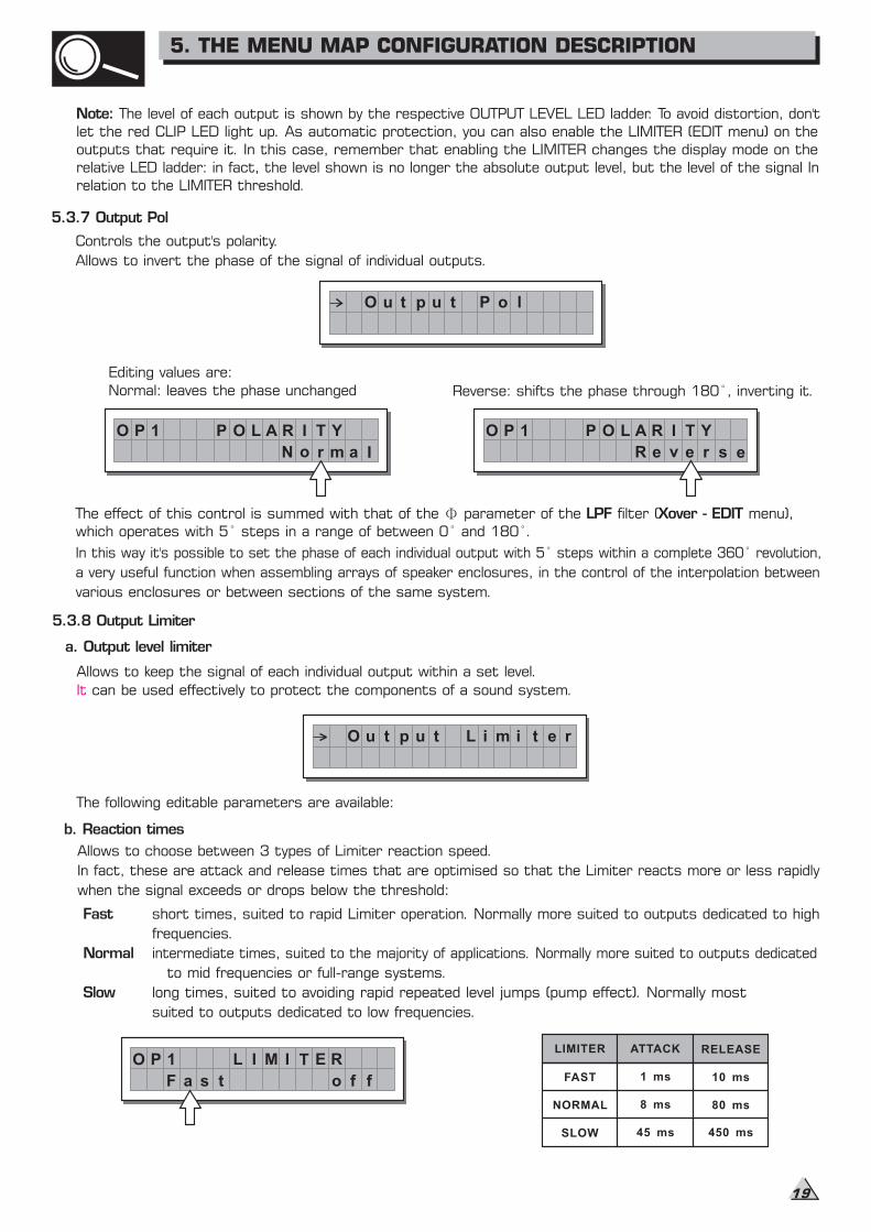
5.3.8 Output Limiter
a. Output level limiter
Allows to keep the signal of each individual output within a set level.
It can be used effectively to protect the components of a sound system.
The following editable parameters are available:
b. Reaction times
Allows to choose between 3 types of Limiter reaction speed.
In fact, these are attack and release times that are optimised so that the Limiter reacts more or less rapidly
when the signal exceeds or drops below the threshold:
Fast
Normal
to mid frequencies or full-range systems.
Slow
suited to outputs dedicated to low frequencies.
Normal: leaves the phase unchanged Reverse: shifts the phase through 180 , inverting it.
LIMITER
FAST
NORMAL
SLOW
ATTACK RELEASE
1 ms 10 ms
8 ms 80 ms
45 ms 450 ms
O P 1
N o r m
P O L A
a I
R I T Y O P 1
e v e r
P O L A
s e
R I T Y
R
O u t p u t L i m i t e r
O P 1
f
L I M I T E R
fosaF t
short times, suited to rapid Limiter operation. Normally more suited to outputs dedicated to high
frequencies.
intermediate times, suited to the majority of applications. Normally more suited to outputs dedicated
long times, suited to avoiding rapid repeated level jumps (pump effect). Normally most
The effect of this control is summed with that of the parameter of the filter ( menu),
which operates with 5 steps in a range of between 0 and 180 .
LPF Xover - EDIT
In this way it's possible to set the phase of each individual output with 5 steps within a complete 360 revolution,
a very useful function when assembling arrays of speaker enclosures, in the control of the interpolation between
various enclosures or between sections of the same system.
Note: The level of each output is shown by the respective OUTPUT LEVEL LED ladder. To avoid distortion, don't
let the red CLIP LED light up. As automatic protection, you can also enable the LIMITER (EDIT menu) on the
outputs that require it. In this case, remember that enabling the LIMITER changes the display mode on the
relative LED ladder: in fact, the level shown is no longer the absolute output level, but the level of the signal In
relation to the LIMITER threshold.
5.3.7 Output Pol
Controls the output's polarity.
Allows to invert the phase of the signal of individual outputs.
Editing values are:
O u t p u t P o l
5. THE MENU MAP CONFIGURATION DESCRIPTION
19
5.4 UTILITY Menu
menu
UTILITYGanging
Lock
Memory Card
Input Ganging
Output Ganging
Delay Unit
Lim. Thresh. Unit
Lock
Format Card
Preset Change RX
Units
Temperature Unit
Input Select
Output Meters
Misc. Setup
Temperature
Wake Up
LCD Contrast
Comm.Setup
ID Select
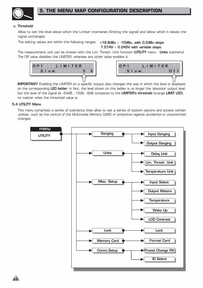
IMPORTANT! Enabling the LIMITER on a specific output also changes the way in which the level is displayed
on the corresponding In fact, the level shown on this ladder is no longer the "absolute" output level,LED ladder:
but the level of the signal at -24dB, -12dB, -6dB compared to the (orange ),LIMITER's threshold LIMIT LED
no matter what the threshold value is.
This menu comprises a series of submenus that allow to set a series of system options and access certain
utilities, such as the control of the Multimedia Memory CARD or protection against accidental or unauthorized
changes:
c. Threshold
signal unchanged.
The editing values are within the following ranges: +19.8dBu ~ -10dBu, with 0.2dBu steps
7.574V ~ 0.245V with variable steps
The Off value disables the LIMITER, whereas any other value enables it.
O P 1
8
L I M I T E R
5olS w .
O P 1
f
L I M I T E R
fOolS w
Allow to set the level above which the Limiter intervenes (limiting the signal) and below which it leaves the
The measurement unit can be chosen with the Lim. Thresh. Unit function ( menu - submenu).UTILITY Units
5. THE MENU MAP CONFIGURATION DESCRIPTION
20
To check this:
1. set Input Gangin=Off, load the *Default* PRESET, set INA Delay=1 and INB Delay=0;
2. set Input Gangin=On, return to the Input Delay menu: the display shows INA&B Delay=1:
a. if you leave the value unchanged and once again set Input Gangin=Off
going back to the Input Delay menu, the display shows INA Delay=1 and INB Delay=0 ("original" values).
b. if you change the value, for example INA&B Delay=3, and you once again set Input Gangin=Off
going back to the Input Delay menu, the display shows INA Delay=3 and INB Delay=3 ("new" values).
G a n g i n g
The practical use of the Ganging function consists in the possibility of editing with identical values the parameters
of similar elements, carrying out single (instead of double) operations.
For example, it's possible to set the same Delay value or equalization on both inputs with just one operation;
or set identical Xover parameters for the various outputs fed to a stereo sound system; or yet again, enable
The LIMITER simultaneously on the two outputs dedicated to two mono stage monitors.
The system automatically recognizes incompatible elements contained in the various configurations and only
enables the Ganging function where it can effectively be used. Therefore, the Ganging function doesn't have
any effect on the MONO setups. The Ganging function can be enabled separately for both groups of input and
groups of outputs.
IMPORTANT: Precisely for its characteristics, the Ganging function affects the way in which the relative
parameters audio are edited or represented:
As soon as Inputs and/or Outputs are ganged, the various menu pages only show the values that can actually
be used. This however doesn't mean that the values change immediately. On the contrary, the values remain
unchanged (Even if not shown) until new values are entered. Only at that point ganged, Inputs and/or Outputs
assume the same value with the just one operation.
For example, even if the display shows that "Input A&B" are ganged in the page with a certain parameter, the
value shown remains that of Input A until a new value is entered, as Input B doesn't automatically assume the
values of Input A.
This condition is used to avoid accidental or temporary enabling of the Ganging function from changing the values
of all the stored PRESET. The rule can be summed up as follows: "only the values that have to be intentionally
changed are changed".
So generally speaking, to avoid contradictions, oversights and confusion between what is shown and what is
effectively carried out, it s advisable to enable the Ganging functions before starting to edit a PRESET. Moreover,
it s best to make certain to effectively set the required value, manually confirming all the parameters required.
Note: The elements in Ganging assume the "new" value as soon as the DIAL changes the status of the "old "
value. So, if the value which has to be allocated to the elements in Ganging is the same as the old value, it's
necessary to use the DIAL, temporarily change the value (even only by one step) and then go back to the "old"
value.
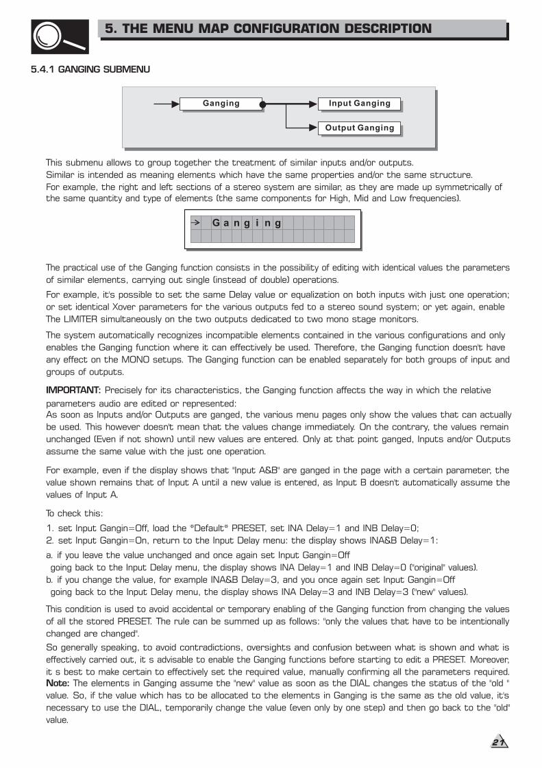
5.4.1 GANGING SUBMENU
Ganging Input Ganging
Output Ganging
This submenu allows to group together the treatment of similar inputs and/or outputs.
Similar is intended as meaning elements which have the same properties and/or the same structure.
For example, the right and left sections of a stereo system are similar, as they are made up symmetrically of
the same quantity and type of elements (the same components for High, Mid and Low frequencies).
5. THE MENU MAP CONFIGURATION DESCRIPTION
21
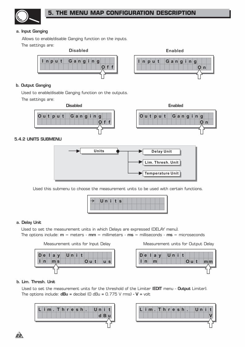
b. Output Ganging
Used to enable/disable Ganging function on the outputs.
The settings are:
5.4.2 UNITS SUBMENU
Used this submenu to choose the measurement units to be used with certain functions.
a. Delay Unit
Used to set the measurement units in which Delays are expressed (DELAY menu).
The options include: = meters - = millimeters - = milliseconds - = microsecondsm mm ms ms
b. Lim. Thresh. Unit
Used to set the measurement units for the threshold of the Limiter ( menu - Limiter).EDIT Output
The options include: decibel (0 dBu 0.775 V rms) voltdBu = = - V =
Delay Unit
Lim. Thresh. Unit
Units
Temperature Unit
Disabled
O u t p u t G a n g i n g
O f f
Enabled
O u t p u t G a n g i n g
O n
U n i t s
Measurement units for Input Delay
D e l a y U n i t
I n m s t u sO u
Measurement units for Output Delay
D e l a y U n i t
I n m tO u m m
L i m . T r e s h
V
h . U n i tL i m . T r e s h
ud B
h . U n i t
a. Input Ganging
Allows to enable/disable Ganging function on the inputs.
The settings are:
I n p u t G a n g i n g
O f f
Disabled Enabled
I n p u t G a n g i n g
O n
5. THE MENU MAP CONFIGURATION DESCRIPTION
22

5.4.3 Misc. Setup submenu
Use this submenu to set a series of system options.
a. Input Select
Used to choose which MAXIDRIVE3.4+ should use.inputs
The options include:
The inputs selected become and Input .
Any signal on the inputs not selected is ignored.
Input A B
b. Output Meters
Used to decide whether to display the outputs signal before or after MUTE.
The options include:
Input Select
Output Meters
Misc. Setup
Temperature
Wake Up
LCD Contrast
M i s c . S e t u p
I n p u t S e l e c t
A n a l o g
PreMutethe signal is always shown
no matter what the MUTE status
u t p u t M e t e r s
P r e M t e
O
u
PostMutethe signal is only shown ifthe output isn't in MUTE
u t p u t M e t e r s
o s t M t e
O
uP
I n p u t S e l e c t
i g i t a lD
Digital Inputs Analog Inputs
c. Temperature Unit
Used to set the measurement units for the Temperature function ( menu - Misc. Setup submenu).
The options include: degrees Centigrade - degrees Fahrenheit
UTILITY
F =C =
T e m P e ut
C
r U n i ta er T e m P e ut
F
r U n i ta er
Apparaten skall anslutas tilljordat uttag nar den anslutstill ett natverk
PWR
OFF
ON
AC INPUT 14W95-240V 50/60HzFUSE: 95-120V T500mAL
210-240V T315mAL
DIGITAL IN RS485 OUT RS485 IN RS232 INPUT AINPUT B4 3 2 1
OUTPUTS
56
A102
DESIGNED IN ITALYMADE IN CHINA
PUSH
2 13
NEW TIDE
PUSH
2 13
NEW TIDE
PUSH
1
3
2
NEW TIDE
PUSH
1
3
2
NEW TIDE
5. THE MENU MAP CONFIGURATION DESCRIPTION
23
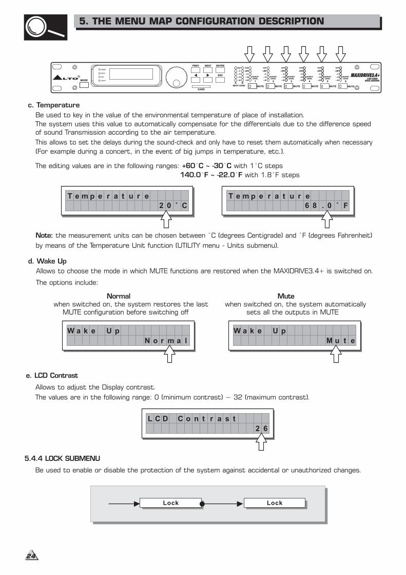
c. Temperature
Be used to key in the value of the environmental temperature of place of installation.
The system uses this value to automatically compensate for the differentials due to the difference speed
of sound Transmission according to the air temperature.
This allows to set the delays during the sound-check and only have to reset them automatically when necessary
(For example during a concert, in the event of big jumps in temperature, etc.).
The editing values are in the following ranges: with 1 C steps+60 C ~ -30 C
with 1.8 F steps140.0 F ~ -22.0 F
Note: the measurement units can be chosen between C (degrees Centigrade) and F (degrees Fahrenheit)
by means of the Temperature Unit function (UTILITY menu - Units submenu).
d. Wake Up
Allows to choose the mode in which MUTE functions are restored when the MAXIDRIVE3.4+ is switched on.
The options include:
e. LCD Contrast
Allows to adjust the Display contrast.
The values are in the following range: 0 (minimum contrast) ~ 32 (maximum contrast).
5.4.4 LOCK SUBMENU
Be used to enable or disable the protection of the system against accidental or unauthorized changes.
Lock Lock
T e m p e r a t u r e
2 0 C
T e m p e r a t u r e
F6 8 . 0
Mutewhen switched on, the system automatically
sets all the outputs in MUTE
Normalwhen switched on, the system restores the last
MUTE configuration before switching off
N o r m a l
W a k e U p
2 6
L C D C o n t r a s t
W a k e U p
M u t e
ENTERPREV NEXT
ESC
MODE
CLIP
66
1212
1818
2424
A BINPUT LEVELINPUT LEVEL MUTE
CLIP
66
1212
2424
LIMIT
OUTPUTLEVEL
OUTPUTLEVEL
CLIP
66
1212
2424
LIMIT
CLIP
66
1212
2424
LIMIT
CLIP
66
1212
2424
LIMIT
CLIP
66
1212
2424
LIMIT
CLIPCLIP
66
1212
2424
LIMIT
OUTPUTLEVEL
OUTPUTLEVEL
OUTPUTLEVEL
OUTPUTLEVEL
OUTPUTLEVEL
OUTPUTLEVEL
OUTPUTLEVEL
OUTPUTLEVEL
OUTPUTLEVEL
OUTPUTLEVEL
MUTE MUTEMUTE MUTE MUTE MUTEMUTE
CARD
3-WAY STEREODIGITAL CROSSOVER
3-WAY STEREODIGITAL CROSSOVER
MAXIDRIVE3.4+
1 2 3 4 5 6
R
LTOEDIT
UTILITY
DELAY
PRESET
5. THE MENU MAP CONFIGURATION DESCRIPTION
24
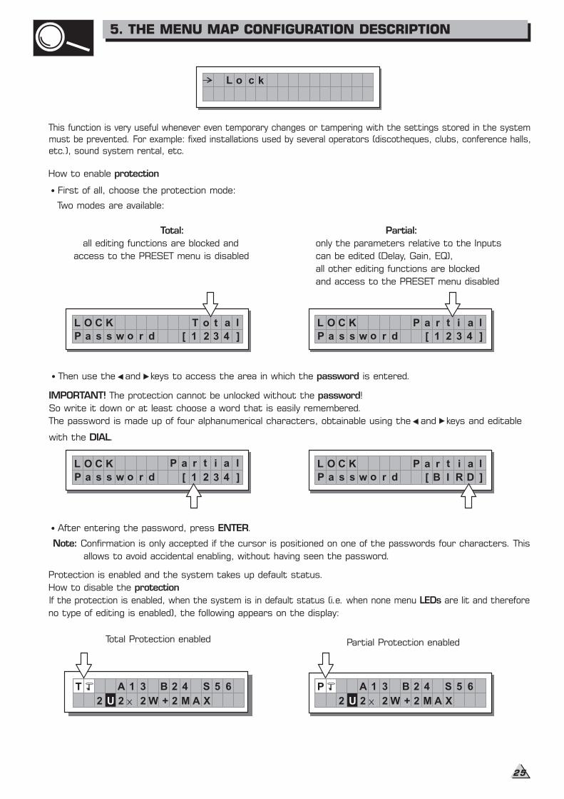
How to enable protection
First of all, choose the protection mode:
Two modes are available:
Total: Partial:
all editing functions are blocked and only the parameters relative to the Inputs
access to the PRESET menu is disabled can be edited (Delay, Gain, EQ),
all other editing functions are blocked
and access to the PRESET menu disabled
After entering the password, press .ENTER
Confirmation is only accepted if the cursor is positioned on one of the passwords four characters. ThisNote:
allows to avoid accidental enabling, without having seen the password.
Protection is enabled and the system takes up default status.
How to disable the protection
If the protection is enabled, when the system is in default status (i.e. when none menu are lit and thereforeLEDs
no type of editing is enabled), the following appears on the display:
L o c k
L O C K T o t a l
P a s s w o r d [ 1 2 3 4 ]
L O C K r it a l
P a s s w o r d [ 1 2 3 4 ]
P a
L O C K r it a l
P a s s w o r d [ B I R D ]
P aL O C K
P a s s w o r d [ 1 2 3 4 ]
r it a lP a
Total Protection enabled
T A 1 3 B 2 4 S 5 6
2 U 2 2 W + 2 M A X
Partial Protection enabled
P A 1 3 B 2 4 S 5 6
2 U 2 2 W + 2 M A X
This function is very useful whenever even temporary changes or tampering with the settings stored in the system
must be prevented. For example: fixed installations used by several operators (discotheques, clubs, conference halls,
etc.), sound system rental, etc.
Then use the and keys to access the area in which the is entered.password
IMPORTANT! passwordThe protection cannot be unlocked without the !
So write it down or at least choose a word that is easily remembered.
The password is made up of four alphanumerical characters, obtainable using the and keys and editable
with the .DIAL
5. THE MENU MAP CONFIGURATION DESCRIPTION
25
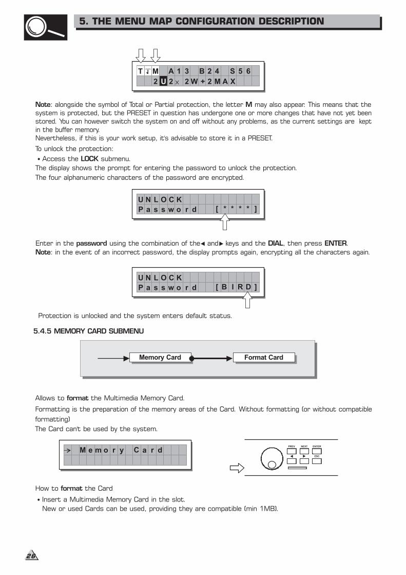
Note: in the event of an incorrect password, the display prompts again, encrypting all the characters again.
Protection is unlocked and the system enters default status.
5.4.5 MEMORY CARD SUBMENU
Allows to the Multimedia Memory Card.format
The Card can't be used by the system.
How to the Cardformat
Insert a Multimedia Memory Card in the slot.
New or used Cards can be used, providing they are compatible (min 1MB).
To unlock the protection:
Access the submenu.LOCK
The display shows the prompt for entering the password to unlock the protection.
The four alphanumeric characters of the password are encrypted.
Memory Card Format CardMemory Card Format Card
ENTERPREV NEXT
ESC
Note M: alongside the symbol of Total or Partial protection, the letter may also appear. This means that the
system is protected, but the PRESET in question has undergone one or more changes that have not yet been
stored. You can however switch the system on and off without any problems, as the current settings are kept
in the buffer memory.
Nevertheless, if this is your work setup, it's advisable to store it in a PRESET.
Enter in the using the combination of the and keys and the , then press .password DIAL ENTER
T M A 1 3 B 2 4 S 5 6
2 U 2 2 W + 2 M A X
U N L O C K
[ * * * * ]P a s s w o r d
U N L O C K
[ B I R D ]P a s s w o r d
M e m o r y C a r d
Formatting is the preparation of the memory areas of the Card. Without formatting (or without compatible
formatting)
5. THE MENU MAP CONFIGURATION DESCRIPTION
26

5.4.6 COMM. SETUP SUBMENU
ATTENTION!
ENTER
Formatting cancels any data contained in the Card.
In the Memory Card submenu, press .
Note: in the event of an error or a Card fault, if there is no Card in the slot or if the Card is removed during
formatting, the display shows the following message:
This submenu allows access to the setting of communication with other units via the serial ports.
Note: Dump Out Preset Incoming Dumpthe and functions are an exception, as they're controlled directly in
the menu.PRESET
PRESET Change RX
Allows to accept or ignore the PRESET Change command sent via the serial ports from a computer or another
MAXIDRIVE3.4+ when it loads a PRESET.
The settings can be:
Ignore PRESET Change commands received. Accept and execute PRESET Change commands.
Press ENTER.
The system formats the Card until it communicates that it has completed.
During formatting, the system automatically stores the *Default* PRESET in all the 128 CARD memory areas.
Note: since the system must always be configured, there are no empty memory areas. All the User and
Card whichareas not yet used by stored user data are automatically occupied by the *Default* PRESET,
contains a standard start configuration with all the values of the various parameters at zero.
The Format Card page appears
This operation only requires a few seconds. The Card is ready to be used.
Comm. Setup Preset Change RXComm. Setup Preset Change RX
Preset Change RXID Select
F o r a t C am dr
F o r a t C am dr
F o r a tm t i n g . . .
F o r a t C am dr
F o r a tm D o n e !
F o r a t C am dr
F o r a tm E r r o r !
C mo . S t u pm e
P er e t C h as n g e R X
A c c e p t
P er e t C h as n g e R X
I g n o r e
5. THE MENU MAP CONFIGURATION DESCRIPTION
27
SEND ACCEPT IGNORE
..
Preset #2
Preset #3
Preset #4
Preset #5
Preset #6
Preset #7
Preset #8
Preset #9
..
#2 MySetup
#3 MySetup5
#4 LiveSet1
#5 LiveSet2
#6 Monitor
#7 Monitor2
#8 Monitor3
#9 Side
..
..
#2 SideField
#3 Concert1
#4 Concert2
#5 Concert3
#6 Concert4
#7 Remote1
#8 Remote2
#9 Remote2
..
Preset Change RX
MAXIDRIVE3.4+ #2
Load Preset
MAXIDRIVE3.4+ #1
Preset Change RX
MAXIDRIVE3.4+ #3
SE
RIA
LP
OR
T
SE
RIA
LP
OR
T
..
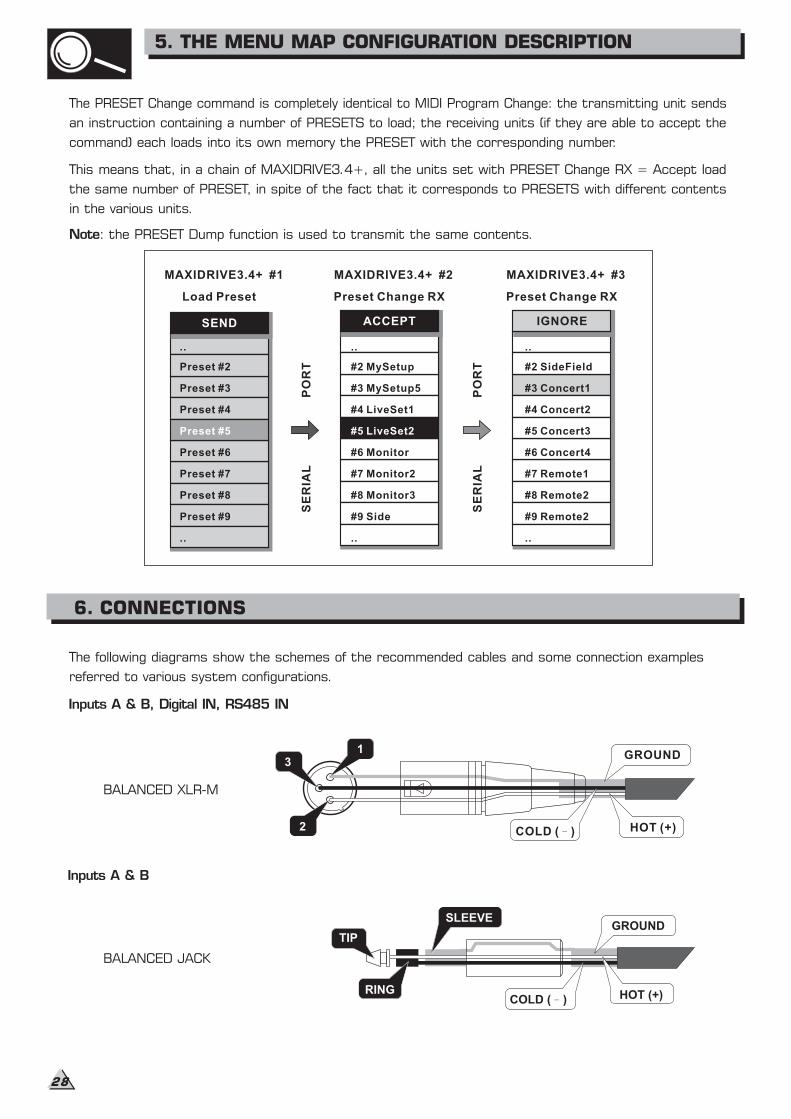
The following diagrams show the schemes of the recommended cables and some connection examples
various system configurations.referred to
Inputs A & B, Digital IN, RS485 IN
31
2
GROUND
HOT (+)COLD ( )
Inputs A & B
GROUND
HOT (+)COLD ( )RING
SLEEVE
TIP
BALANCED XLR-M
BALANCED JACK
The PRESET Change command is completely identical to MIDI Program Change: the transmitting unit sends
an instruction containing a number of PRESETS to load; the receiving units (if they are able to accept the
command) each loads into its own memory the PRESET with the corresponding number.
This means that, in a chain of MAXIDRIVE3.4+, all the units set with PRESET Change RX = Accept load
the same number of PRESET, in spite of the fact that it corresponds to PRESETS with different contents
in the various units.
Note: the PRESET Dump function is used to transmit the same contents.
5. THE MENU MAP CONFIGURATION DESCRIPTION
6. CONNECTIONS
28
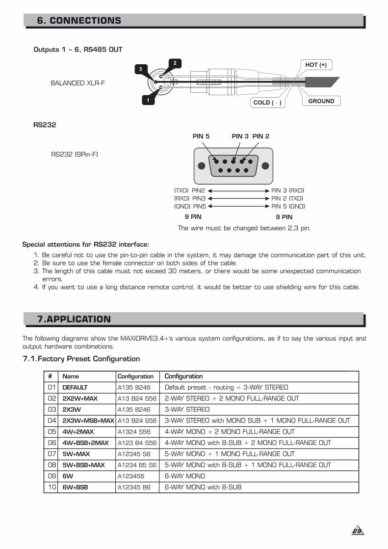
The following diagrams show the MAXIDRIVE3.4+'s various system configurations, as if to say the various input and
output hardware combinations.
#
01
02
03
04
05
06
07
08
09
10
Name
DEFAULT
2X2W+MAX
2X3W
2X3W+MSB+MAX
4W+2MAX
4W+BSB+2MAX
5W+MAX
5W+BSB+MAX
6W
6W+BSB
Configuration
A135 B246
A13 B24 S56
A135 B246
A13 B24 S56
A1324 S56
A123 B4 S56
A12345 S6
A1234 B5 S6
A123456
A12345 B6
Configuration
Default preset - routing = 3-WAY STEREO
2-WAY STEREO + 2 MONO FULL-RANGE OUT
3-WAY STEREO
3-WAY STEREO with MONO SUB + 1 MONO FULL-RANGE OUT
4-WAY MONO + 2 MONO FULL-RANGE OUT
4-WAY MONO with B-SUB + 2 MONO FULL-RANGE OUT
5-WAY MONO + 1 MONO FULL-RANGE OUT
5-WAY MONO with B-SUB + 1 MONO FULL-RANGE OUT
6-WAY MONO
6-WAY MONO with B-SUB
Outputs 1 ~ 6, RS485 OUT
GROUND
HOT (+)
COLD ( )
3
2
1
BALANCED XLR-F
7.1.Factory Preset Configuration
RS232
RS232 (9Pin-F)
PIN 5 PIN 3 PIN 2
(RXD) PIN3
(GND) PIN5
(TXD) PIN2 PIN 3 (RXD)
PIN 2 (TXD)
PIN 5 (GND)
The wire must be changed between 2,3 pin.
9 PIN9 PIN
Special attentions for R 232 interface:S
1. Be careful not to use the pin-to-pin cable in the system, it may damage the communication part of this unit.
2. Be sure to use the female connector on both sides of the cable.
3. The length of this cable must not exceed 30 meters, or there would be some unexpected communication
errors.
4. If you want to use a long distance remote control, it would be better to use shielding wire for this cable.
6. CONNECTIONS
7.APPLICATION
29
OP1&2
OP3&4
OP5&6
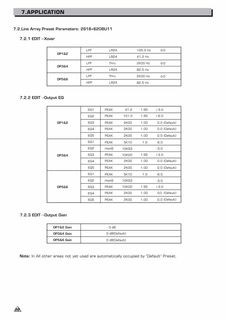
LPF
HPF
LPF
HPF
LPF
HPF
LR24
LR24
Thru
LR24
Thru
LR24
7.2.Line Array Preset Parameters: 2S18+6208U11
125.0 Hz
41.2 Hz
2K00 Hz
82.5 Hz
2K00 Hz
82.5 Hz
0
OP1&2
OP3&4
OP5&6
EQ1
EQ2
EQ3
EQ4
EQ5
PEAK 41.2 1.95 +3.0
PEAK 101.0 1.95 +6.0
PEAK 2K00 1.00 0.0 (Default)
PEAK 2K00 1.00 0.0 (Default)
PEAK 2K00 1.00 0.0 (Default)
PEAK 5K10 1.0 -6.0EQ1
EQ2
EQ3
EQ4
EQ5
EQ1
EQ2
EQ3
EQ4
EQ5
Hish6 10K93 -3.0
PEAK 10K20 1.95 +3.0
PEAK 2K00 1.00 0.0 (Default)
PEAK 2K00 1.00 0.0 (Default)
PEAK 5K10 1.0 -6.0
Hish6 10K93 -3.0
PEAK 10K20 1.95 +3.0
PEAK 2K00 1.00 0.0 (Default)
PEAK 2K00 1.00 0.0 (Default)
OP1&2 Gain - 3 dB
OP3&4 Gain 0 dB(Default)
OP5&6 Gain 0 dB(Default)
0
0
Note: In All other areas not yet used are automatically occupied by "Default" Preset.
7.2.3 EDIT Output Gain
7.2.2 EDIT Output EQ
7.2.1 EDIT Xover
7.APPLICATION
30

D3750W 2
(dB)
12
16
1820
22
24
26
28
30
6
CH1 (dB)
12
16
1820
22
24
26
28
30
6
CH2
SIG CLIP PROT SIG CLIP PROT
D3750W 2
(dB)
12
16
1820
22
24
26
28
30
6
CH1 (dB)
12
16
1820
22
24
26
28
30
6
CH2
SIG CLIP PROT SIG CLIP PROT
D3750W 2
(dB)
12
16
1820
22
24
26
28
30
6
CH1 (dB)
12
16
1820
22
24
26
28
30
6
CH2
SIG CLIP PROT SIG CLIP PROT
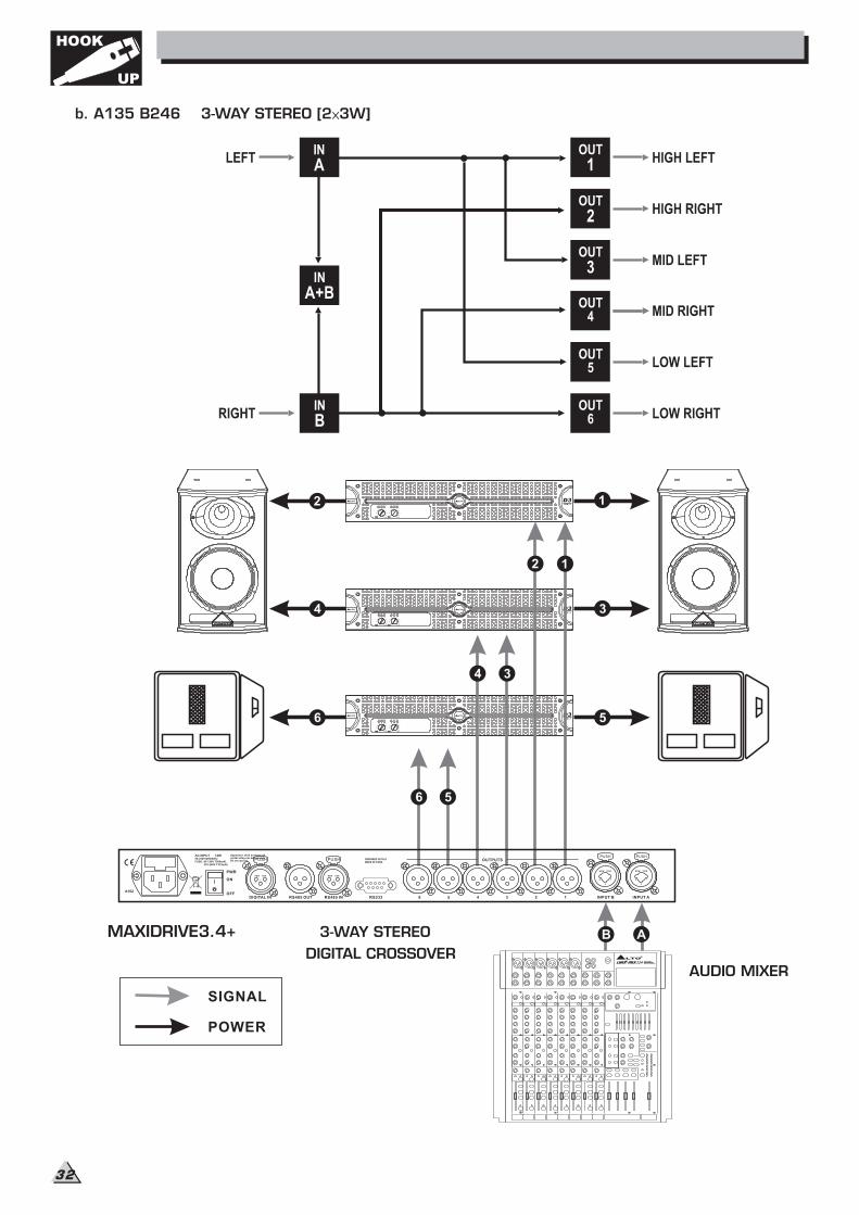
7.3 Hookup
The following examples will help you well use and connect the unit.
a. A13 B24 S56 2-WAY STEREO+2 MONO AUX [2 2W+2MAX]
MAXIDRIVE3.4+ 3-WAY STEREO
DIGITAL CROSSOVERAUDIO MIXER
SIGNAL
POWER
1
2
3
4
5
6
4
6
5
3
2
1
AB
Apparaten skall anslutas tilljordat uttag nar den anslutstill ett natverk
PWR
OFF
ON
AC INPUT 14W95-240V 50/60HzFUSE: 95-120V T500mAL
210-240V T315mAL
DIGITAL IN RS485 OUT RS485 IN RS232 INPUT AINPUT B4 3 2 1
OUTPUTS
56
A102
DESIGNED IN ITALYMADE IN CHINA
PUSH
2 13
NEW TIDE
PUSH
2 13
NEW TIDE
PUSH
1
3
2
NEW TIDE
PUSH
1
3
2
NEW TIDE
HOOK
UP
31
D3750W 2
(dB)
12
16
1820
22
24
26
28
30
6
CH1 (dB)
12
16
1820
22
24
26
28
30
6
CH2
SIG CLIP PROT SIG CLIP PROT
D3750W 2
(dB)
12
16
1820
22
24
26
28
30
6
CH1 (dB)
12
16
1820
22
24
26
28
30
6
CH2
SIG CLIP PROT SIG CLIP PROT
D3750W 2
(dB)
12
16
1820
22
24
26
28
30
6
CH1 (dB)
12
16
1820
22
24
26
28
30
6
CH2
SIG CLIP PROT SIG CLIP PROT
b. A135 B246 3-WAY STEREO [2 3W]
MAXIDRIVE3.4+ 3-WAY STEREO
DIGITAL CROSSOVERAUDIO MIXER
SIGNAL
POWER
1
2
3
4
5
6
4
6
5
3
2
1
AB
Apparaten skall anslutas tilljordat uttag nar den anslutstill ett natverk
PWR
OFF
ON
AC INPUT 14W95-240V 50/60HzFUSE: 95-120V T500mAL
210-240V T315mAL
DIGITAL IN RS485 OUT RS485 IN RS232 INPUT AINPUT B4 3 2 1
OUTPUTS
56
A102
DESIGNED IN ITALYMADE IN CHINA
PUSH
2 13
NEW TIDE
PUSH
2 13
NEW TIDE
PUSH
1
3
2
NEW TIDE
PUSH
1
3
2
NEW TIDE
HOOK
UP
32
D3750W 2
(dB)
12
16
1820
22
24
26
28
30
6
CH1 (dB)
12
16
1820
22
24
26
28
30
6
CH2
SIG CLIP PROT SIG CLIP PROT
D3750W 2
(dB)
12
16
1820
22
24
26
28
30
6
CH1 (dB)
12
16
1820
22
24
26
28
30
6
CH2
SIG CLIP PROT SIG CLIP PROT
D3750W 2
(dB)
12
16
1820
22
24
26
28
30
6
CH1 (dB)
12
16
1820
22
24
26
28
30
6
CH2
SIG CLIP PROT SIG CLIP PROT
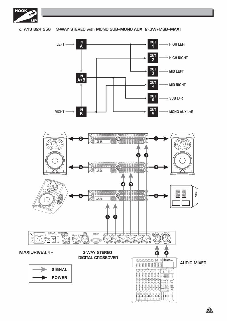
c. A13 B24 S56 3-WAY STEREO with MONO SUB+MONO AUX [2 3W+MSB+MAX]
MAXIDRIVE3.4+ 3-WAY STEREO
DIGITAL CROSSOVER
AUDIO MIXER
SIGNAL
POWER
1
2
3
4
5
6
4
6
5
3
2
1
AB
Apparaten skall anslutas tilljordat uttag nar den anslutstill ett natverk
PWR
OFF
ON
AC INPUT 14W95-240V 50/60HzFUSE: 95-120V T500mAL
210-240V T315mAL
DIGITAL IN RS485 OUT RS485 IN RS232 INPUT AINPUT B4 3 2 1
OUTPUTS
56
A102
DESIGNED IN ITALYMADE IN CHINA
PUSH
2 13
NEW TIDE
PUSH
2 13
NEW TIDE
PUSH
1
3
2
NEW TIDE
PUSH
1
3
2
NEW TIDE
HOOK
UP
33
D3750W 2
(dB)
12
16
1820
22
24
26
28
30
6
CH1 (dB)
12
16
1820
22
24
26
28
30
6
CH2
SIG CLIP PROT SIG CLIP PROT
D3750W 2
(dB)
12
16
1820
22
24
26
28
30
6
CH1 (dB)
12
16
1820
22
24
26
28
30
6
CH2
SIG CLIP PROT SIG CLIP PROT
D3750W 2
(dB)
12
16
1820
22
24
26
28
30
6
CH1 (dB)
12
16
1820
22
24
26
28
30
6
CH2
SIG CLIP PROT SIG CLIP PROT
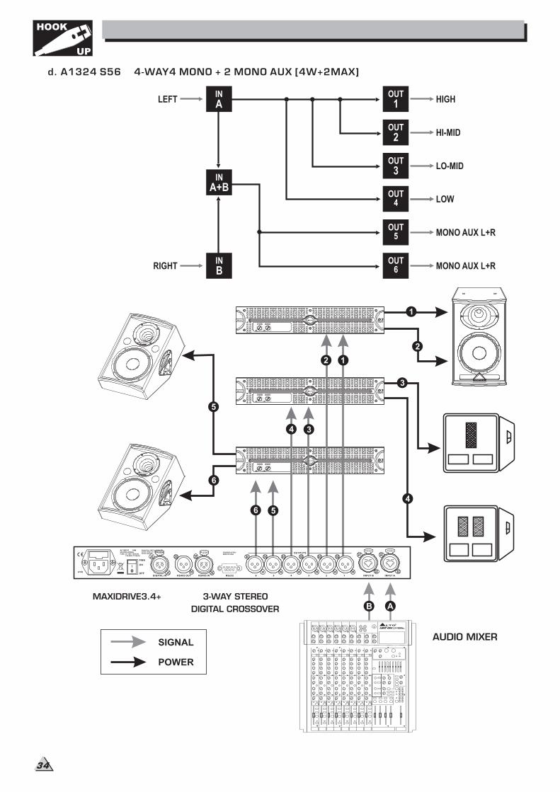
d. A1324 S56 4-WAY4 MONO + 2 MONO AUX [4W+2MAX]
SIGNAL
POWER
MAXIDRIVE3.4+ 3-WAY STEREO
DIGITAL CROSSOVER
AUDIO MIXER
12
34
56
5
6
1
2
3
4
AB
Apparaten skall anslutas tilljordat uttag nar den anslutstill ett natverk
PWR
OFF
ON
AC INPUT 14W95-240V 50/60HzFUSE: 95-120V T500mAL
210-240V T315mAL
DIGITAL IN RS485 OUT RS485 IN RS232 INPUT AINPUT B4 3 2 1
OUTPUTS
56
A102
DESIGNED IN ITALYMADE IN CHINA
PUSH
2 13
NEW TIDE
PUSH
2 13
NEW TIDE
PUSH
1
3
2
NEW TIDE
PUSH
1
3
2
NEW TIDE
HOOK
UP
34
D3750W 2
(dB)
12
16
1820
22
24
26
28
30
6
CH1 (dB)
12
16
1820
22
24
26
28
30
6
CH2
SIG CLIP PROT SIG CLIP PROT
D3750W 2
(dB)
12
16
1820
22
24
26
28
30
6
CH1 (dB)
12
16
1820
22
24
26
28
30
6
CH2
SIG CLIP PROT SIG CLIP PROT
D3750W 2
(dB)
12
16
1820
22
24
26
28
30
6
CH1 (dB)
12
16
1820
22
24
26
28
30
6
CH2
SIG CLIP PROT SIG CLIP PROT
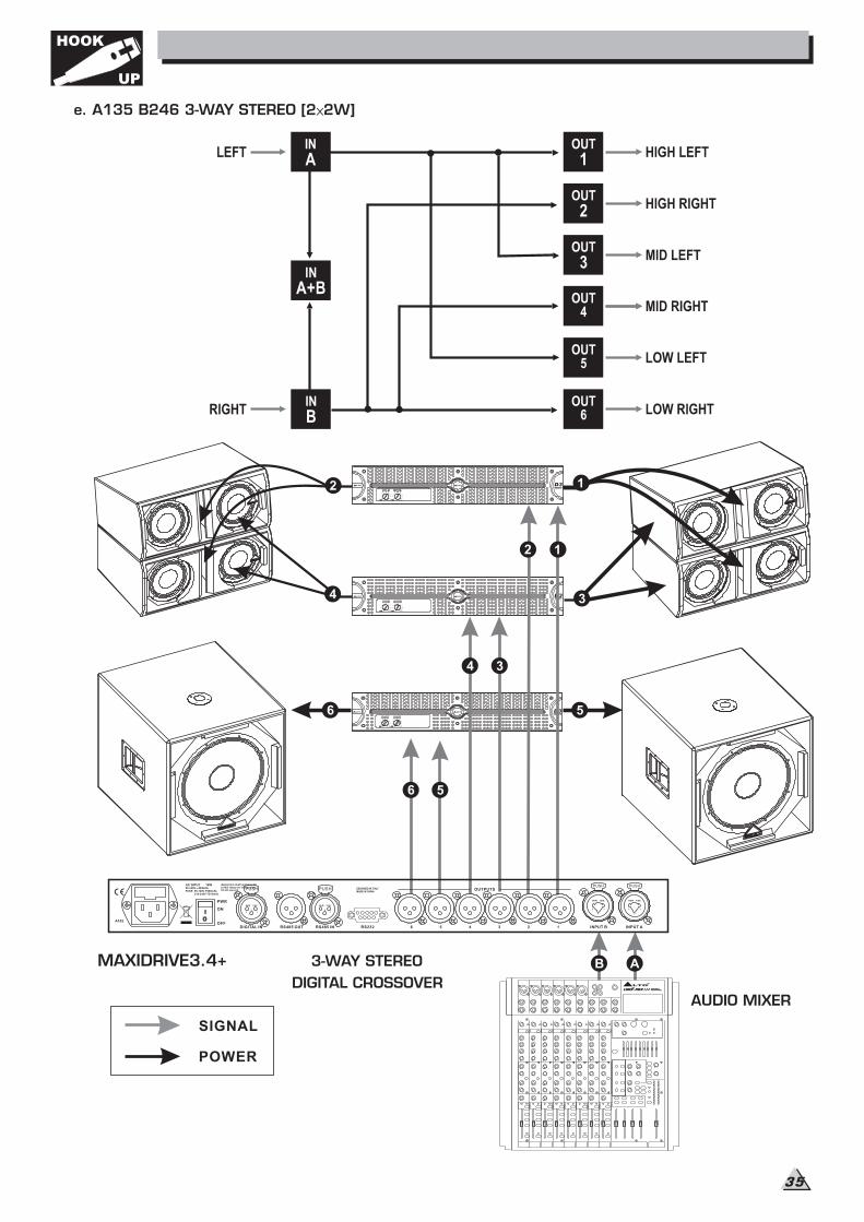
e. A135 B246 3-WAY STEREO [2 2W]
MAXIDRIVE3.4+ 3-WAY STEREO
DIGITAL CROSSOVERAUDIO MIXER
SIGNAL
POWER
1
3
5
6
4
6
5
1
AB
2
4 3
2
Apparaten skall anslutas tilljordat uttag nar den anslutstill ett natverk
PWR
OFF
ON
AC INPUT 14W95-240V 50/60HzFUSE: 95-120V T500mAL
210-240V T315mAL
DIGITAL IN RS485 OUT RS485 IN RS232 INPUT AINPUT B4 3 2 1
OUTPUTS
56
A102
DESIGNED IN ITALYMADE IN CHINA
PUSH
2 13
NEW TIDE
PUSH
2 13
NEW TIDE
PUSH
1
3
2
NEW TIDE
PUSH
1
3
2
NEW TIDE
HOOK
UP
35
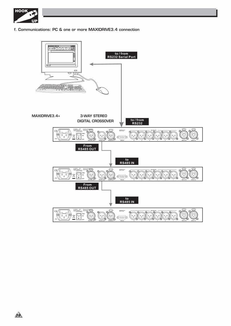
FromRS485 OUT
toRS485 IN
FromRS485 OUT
toRS485 IN
to / fromRS232
to / fromRS232 Serial Port
MAXIDRIVE3.4+ 3-WAY STEREO
DIGITAL CROSSOVER
f. Communications: PC & one or more MAXIDRIVE3.4 connection
Apparaten skall anslutas tilljordat uttag nar den anslutstill ett natverk
PWR
OFF
ON
AC INPUT 14W95-240V 50/60HzFUSE: 95-120V T500mAL
210-240V T315mAL
DIGITAL IN RS485 OUT RS485 IN RS232 INPUT AINPUT B4 3 2 1
OUTPUTS
56
A102
DESIGNED IN ITALYMADE IN CHINA
PUSH
2 13
NEW TIDE
PUSH
2 13
NEW TIDE
PUSH
1
3
2
NEW TIDE
PUSH
1
3
2
NEW TIDE
HOOK
UP
36
8. TECHNICAL SPECIFICATIONS
37
INPUT Section
Output Section
DSP Section
Features
General Performance
General
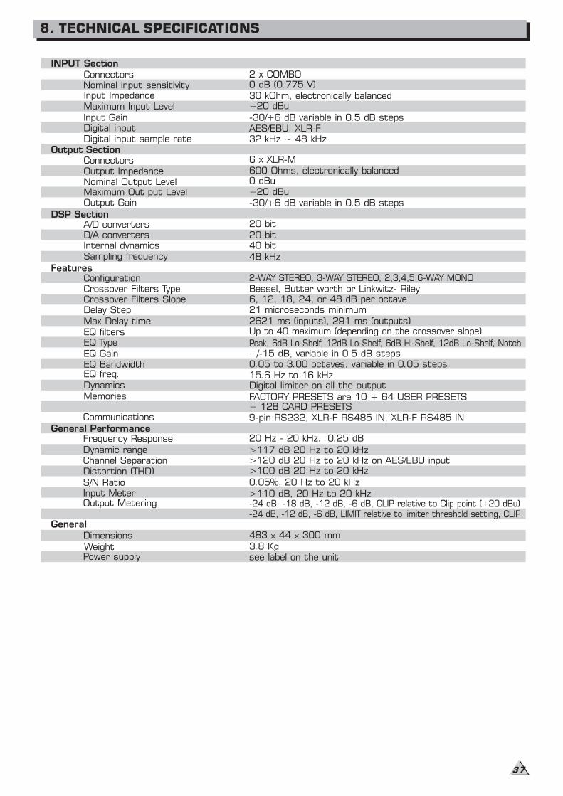
Peak, 6dB Lo-Shelf, 12dB Lo-Shelf, 6dB Hi-Shelf, 12dB Lo-Shelf, Notch
-24 dB, -18 dB, -12 dB, -6 dB, CLIP relative to Clip point (+20 dBu)-24 dB, -12 dB, -6 dB, LIMIT relative to limiter threshold setting, CLIP
Connectors 2 x COMBONominal input sensitivity 0 dB (0.775 V)Input Impedance 30 kOhm, electronically balancedMaximum Input Level +20 dBu
Input Gain -30/+6 dB variable in 0.5 dB stepsDigital input AES/EBU, XLR-FDigital input sample rate 32 kHz ~ 48 kHz
Connectors 6 x XLR-M
Output Impedance 600 Ohms, electronically balanced
Nominal Output Level 0 dBu
Maximum Out put Level +20 dBuOutput Gain -30/+6 dB variable in 0.5 dB steps
A/D converters 20 bit
D/A converters 20 bitInternal dynamics 40 bitSampling frequency 48 kHz
Configuration 2-WAY STEREO, 3-WAY STEREO, 2,3,4,5,6-WAY MONOCrossover Filters Type Bessel, Butter worth or Linkwitz- RileyCrossover Filters Slope 6, 12, 18, 24, or 48 dB per octaveDelay Step 21 microseconds minimum
Max Delay time 2621 ms (inputs), 291 ms (outputs)EQ filters Up to 40 maximum (depending on the crossover slope)
EQ Gain +/-15 dB, variable in 0.5 dB stepsEQ Bandwidth 0.05 to 3.00 octaves, variable in 0.05 stepsEQ freq. 15.6 Hz to 16 kHzDynamics Digital limiter on all the output
+ 128 CARD PRESETSCommunications 9-pin RS232, XLR-F RS485 IN, XLR-F RS485 IN
Frequency Response 20 Hz - 20 kHz, 0.25 dB
Dynamic range >117 dB 20 Hz to 20 kHz>120 dB 20 Hz to 20 kHz on AES/EBU inputChannel Separation>100 dB 20 Hz to 20 kHzDistortion (THD)0.05%, 20 Hz to 20 kHz
Input MeterOutput Metering
Memories FACTORY PRESETS are 10 + 64 USER PRESETS
EQ Type
S/N Ratio
>110 dB 20 Hz to 20 kHz,
Dimensions
WeightPower supply
483 44 300 mm
3.8 Kgsee label on the unit

To obtain Warranty Service, the buyer should first fill out and return the enclosed
Warranty Registration Card within 10 days of the Purchase Date.
All the information presented in this Warranty Registration Card gives the manufacturer a better understanding
of the sales status, so as to provide amore effective and efficient after-sales warranty service. Please fill out
all the information carefully and genuinely, miswriting or absence of this card will voidyour warranty service.
2.1 In case of return for any warranty service, please make sure that the product is well packed in its
original shipping carton, and it can protect your unit from any other extra damage.
2.2 Please provide a copy of your sales receipt or other proof of purchase with the returned machine,
and give detail information about your return address and contact telephone number.
2.3 A brief description of the defect will be appreciated.
2.4 Please prepay all the costs involved in the return shipping, handling and insurance.
3.1 warrants that this product will be free from any defects in materials and/or workmanship for a
period of 1 year from the purchase date if you have completed the Warranty Registration Card in time.
3.2 The warranty service is only available to the original consumer, who purchased this product directly
from the retail dealer, and it can not be transferred.
3.3 During the warranty service, may repair or replace this product at its own option at no charge
to you for parts or for labor in accordance with the right side of this limited warranty.
3.4 This warranty does not apply to the damages to this product that occurred as the following
conditions:
Instead of operating in accordance with the user's manual thoroughly, any abuse or misuse of this product.
Normal tear and wear.
The product has been altered or modified in any way.
Damage which may have been caused either directly or indirectly by another product / force / etc.
Abnormal service or repairing by anyone other than the qualified personnel or technician.
And in such cases, all the expenses will be charged to the buyer.
3.5 In no event shall be liable for any incidental or consequential damages.
Some states do not allow the exclusion or limitation of incidental or consequential damages, so
the above exclusion or limitation may not apply to you.
3.6 This warranty gives you the specific rights, and these rights are compatible with the state laws,
you may also have other statutory rights that may vary from state to state.
LTO
LTO
LTO
38
1. WARRANTY REGISTRATION CARD
2. RETURN NOTICE
3. TERMS AND CONDITIONS
9. WARRANTY

NF02145-1.1.
c
All rights reserved to ALTO. All features and content might be changed
without prior notice. Any photocopy, translation, or reproduction of part of this
manual without written permission is forbidden. Copyright 2007 Seikaku Group
SEIKAKU TECHNICAL GROUP LIMITED
NO. 1, Lane 17, Sec. 2, Han Shi West Road, Taichung 40151, Taiwan
http://www.altoproaudio.com Tel: 886-4-22313737
email: [email protected] Fax: 886-4-22346757