Embed Size (px)
Citation preview
Page 1 of 2
Construction Purchasing Department 16550 SW Merlo Road Beaverton, OR 97003
Phone: 503-356-4441 Fax: 503-356-4475
May 31, 2017 SOLICITATION ADDENDUM NO. 1
ITB 17-0026 ALOHA HIGH SCHOOL DROP CEILING AND LIGHTING REPLACEMENT
THE FOLLOWING CHANGES/ADDITIONS TO THE ABOVE CITED SOLICITATION ARE ANNOUNCED: This Addendum modifies the Invitation to Bid (ITB) document(s) only to the extent indicated herein. All other areas not changed or otherwise modified by this Addendum shall remain in full force and effect. This Addendum is hereby made an integral part of the ITB document. Bidder must be responsive to any requirements of this Addendum as if the requirements were set forth in the ITB. Failure to do so may result in Bid rejection. See the ITB regarding requests for clarification or change and protests of this Addendum, and the deadlines for the foregoing. This addendum is to be acknowledged in the space provided on the Bidder Certification form supplied in the solicitation document. Failure to acknowledge receipt of this addendum may be cause to reject your offer.
The closing date REMAINS UNCHANGED: June 8, 2017 at 2:00 PM Pacific Time
CHANGES:
1. Attachment K Drawings have been split into two (2) parts:
a. Part 1 includes the Phasing Plan and TRC’s Bulk Asbestos Analysis Report dated May 10, 2017. These documents are included in this Addendum but remain unchanged.
b. Part 2 includes OTAK’s Drawings. The “Preliminary – Not for Construction” drawing set included in the original Solicitation is replaced with the “Bid Set” dated May 25, 2017 included as part of this Addendum.
2. All ceiling tile is to be Armstrong School Zone Fine Fissured 1714.
CLARIFICATIONS:
All District Technical Standards are available on the District Facilities website found at the following link:
https://www.beaverton.k12.or.us/depts/facilities/development/Pages/default.aspx BSD Technical Standard Division #1: General Requirements is attached to this Addendum and can be found specifically at: https://www.beaverton.k12.or.us/depts/facilities/development/Documents/2016.12.23%20Tech%20Std%20Div%2001.pdf
BSD Technical Standard Division #9: Paint & Finishes was attached to the end of Attachment J Specifications issued with ITB 17-0026 and can be found specifically at:

Page 2 of 2
https://www.beaverton.k12.or.us/depts/facilities/development/Documents/2016.12.23%20Tech%20Std%20Div%2009.pdf
BSD Technical Standard Division #23: HVAC is attached to this Addendum and can be found specifically at:
https://www.beaverton.k12.or.us/depts/facilities/development/Documents/2014_09%20Tech%20Std%20Div%2023.pdf
Questions submitted via e-mail: Question - Is there an engineer’s estimate for the Aloha High School Drop Ceiling and Lighting Replacement ITB 17-
0026? Answer - No engineer’s estimate has been completed for this project. Question - The ITB has an award date and a substantial completion date, is there a construction start date? Answer - The construction start date is 6/27/2017 as stated in SECTION II - Statement of Work, PURPOSE AND
INTRODUCTION: “All work is to be completed over the 2017 summer break between 06/27/2017 – 09/04/2017.”

BSD Technical Standard Division 1: General Requirements 12/23/16: Rev 2 Page 1 of 8
BSD Technical Standard Division 1: General Requirements
I. PURPOSE
This Technical Standard is a narrative describing the Beaverton School District’s (BSD’s) guiding general requirements. The information contained herein shall be used by the Architect/Engineer (A/E) to properly prepare Division 1 requirements within the Contract Documents (CDs) so that the contract adheres to the BSD’s requirements.
II. E-BUILDER PROJECT MANAGEMENT SYSTEM
The District is now using the e-Builder project management system and we are requiring all of our A/Es and Contractors to use this system as well to conduct the normal communication and work process flows that are used in completing the design and construction of our facilities. Division 1 should reflect that the Contractor use e-Builder to conduct the following work processes:
1. Submission of shop drawings and other submittals and receiving the processed submittals 2. Submission of Requests for Information (RFI) and receiving RFI responses from the Owner and A/E 3. Submission of invoices and approval or rejection of same 4. Distribution of meeting minutes 5. Submission of as-built record drawings 6. Submission of test results and Operation and Maintenance (O&M) manuals (electronic format) 7. Submission of Change Orders (COs) and contract amendment and approval or rejection of same 8. Transmission of formal letters and notices between the District and the Contractor
In the event of occasional operational problems with e-Builder, transmission of the above documents may be done for a temporary period of time by hand carrying, email, normal mail or express mail. Prior approval must be obtained from the District before utilizing this backup communication system and a resumption of e-Builder use is to initiate as soon as the operational problems are corrected.
III. BUILDING INFORMATION MODELING (BIM) The District will require that all major projects be designed using BIM. While the Contractor will not be required to use the BIM model for work sequencing during construction, they may do so at their own election. In Division 1 the A/E needs to indicate the following:
1. The A/E will provide the Contractor with the BIM design model 2. The Contractor, as a minimum, will use the BIM model to coordinate mechanical, electrical, and plumbing routing, given that there will be some changes from the original design due to the submittal approval process.

BSD Technical Standard Division 1: General Requirements 12/23/16: Rev 2 Page 2 of 8
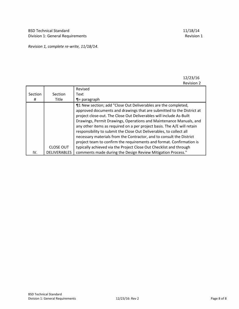
IV. CLOSE OUT DELIVERABLES
Close Out Deliverables are the completed, approved documents and drawings that are submitted to the District at project close out. The Close Out Deliverables will include As-Built Drawings, Permit Drawings, Operations and Maintenance Manuals, and any other items as required on a per project basis. The A/E will retain responsibility to submit the Close Out Deliverables, to collect all necessary materials from the Contractor, and to consult the District project team to confirm the requirements and format. Confirmation is typically achieved via the Project Close Out Checklist and through comments made during the Design Review Mitigation Process.
V. CONSTRUCTION MANAGER/GENERAL CONTRACTOR (CM/GC) DELIVERY PROJECTS
For projects being delivered under the CM/GC model, the A/E will prepare Division 1 in such a manner as to require communication and the flow of transmitted documents to flow from the Trade Contractor to the CM/GC (prime Contractor) and then in parallel to the A/E and the District. Communication and document transmission from the A/E and the District to the Trade Contractor is to occur in the same manner, except that the flow will be the reverse of that noted above.
VI. SECURITY REQUIREMENTS The A/E will require that all personnel under the employment of the Contractor and its Subcontractors that travel to, or spend time at the project site are to wear photo ID badges while on the work site. Individuals not wearing badges will be removed from the project work site. ID badges are to contain:
1. Individual’s full name (no nicknames) 2. Individual’s company affiliation 3. Recent photograph of the individual; taken within the last 4 years
All personnel under the employment of the Contractor and its Subcontractors that spend time at the project site, must be run through formal background screening by the Contractor and pass that screening review, before being allowed on the work site. Background screening is to be done by a professional screening firm meeting the following qualifications:
1. Must have a minimum of five years of screening experience specifically for construction industry clients 2. Must have a minimum of fifteen employees 3. Must be able to provide access to an internet based screening management software system which has a feature to allow access by the District to view the pass-no pass result for each screened Contractor/Subcontractor employee working on a District project 4. Must be accredited by the National Association of Professional Background Screeners (NAPBS)
Each individual will be screened for having committed any crime as listed in ORS 342.143, most recent edition.

BSD Technical Standard Division 1: General Requirements 12/23/16: Rev 2 Page 3 of 8
VII. COMMISSIONING The A/E will prepare the Division 1 requirements to accommodate the following approach;
The District will engage the Commissioning Agent through a direct contract instead of including that work scope under the Contractor as a subcontract. The Commissioning Agent will perform in a Consultant’s role providing:
1. A commissioning plan 2. Monitoring, recording, and reporting commissioning test results 3. Adjustments to allow systems being commissioned to meet design performance criteria
The Contractor will retain responsibility to setup tests, operate equipment and systems, make adjustments to settings and place the systems in final operational mode.
VIII. ASBESTOS PROCEDURES
The A/E will prepare the Division 1 requirements to accommodate the following approach;
The District will directly retain an accredited Asbestos Consultant for all of its projects that involve adding to or renovating existing facilities. The Consultant will provide oversight and recommendations relating to diagnosing the existence of asbestos materials on the site and to mitigation measures. The Consultant will provide documentation regarding the finding of asbestos and mitigation measures as required by the Asbestos Hazard Emergency Response Act and will update the District’s facilities database regarding any asbestos findings.
The Contractor will retain the following responsibilities:
1. Immediately reporting to the District and its Asbestos Consultant the finding of suspected asbestos material 2. Following of any rapid response procedures to isolate District staff, students, facility, visitors, and Contractor staff from the suspected material, while maintaining continued progress on the remainder of the project work 3. Sending a sample of the suspected material to a qualified testing laboratory, receiving test results, and informing the District and their Asbestos Consultant 4. If the material is confirmed to contain asbestos, considering any recommendations from the District and/or its Asbestos Consultant and then implementing asbestos remediation 5. Resuming full scale work activities on the project as soon as the remediation is complete
IX. CODES/PERMIT FEES
It is the Consultant’s responsibility to determine current applicable codes, regulations, and permitting processes. The Consultant is responsible for contacting all applicable jurisdictions in order to review during design and submit completed documents, which comply with applicable codes and regulations.
The District is governed by the Oregon Structural Specialty Code which is an adaptation of the International Building Code. Oregon school facilities are considered essential facilities and thus must meet those structural requirements. The District falls within Seismic Zone 3. Unless

BSD Technical Standard Division 1: General Requirements 12/23/16: Rev 2 Page 4 of 8
otherwise permitted by the BSD Facilities Department, Type V construction shall be limited to temporary and small storage buildings. An analysis of code requirements and ALL required permits for planning, off-site improvements, on-site improvements, structures, and others shall be submitted by the Consultant at the beginning of each project and updated at each phase of design. The permit analysis shall include a processing matrix for each permit. The A/E will prepare the Division 1 requirements to accommodate the following approach; The Consultant will typically file the applications and the District will directly pay the regulating agency for the following:
1. Land use review fees 2. Plan review fees
The Contractor will pay the following permit fees and will invoice the District who will compensate the Contractor as a direct expense (no markup) item that is not included in the contract:
1. Grading permit, if any 2. Building permit 3. Mechanical and plumbing permit 4. Electrical permit
All other permits, fees and licenses required of the Contractor to perform the work will be paid by the Contractor and included in contract value.
X. JURISDICTIONS
A. Land Use/Building & Safety District facilities are primarily located within the jurisdiction of the City of Beaverton and Washington County. There is one facility in the City of Portland’s jurisdiction and one facility in the City of Hillsboro’s jurisdiction. The District is within the jurisdiction of the Washington County Health Department for food facilities. The District is within the jurisdiction of Clean Water Services for storm and sanitary sewer regulations. B. Fire District District facilities are primarily located within the jurisdiction of the Tualatin Valley Fire & Rescue District. There is one facility in Portland Fire’s jurisdiction and one facility in the Hillsboro Fire’s jurisdiction. C. Local Utilities The District is served by several water/sewer service districts depending on site location. NW Natural provides gas service. Portland General Electric (PGE) provides electrical service. Comcast provides cable TV, PCN (data) service, and telephone.

BSD Technical Standard Division 1: General Requirements 12/23/16: Rev 2 Page 5 of 8
D. State Agencies Oregon Department of Transportation Oregon Department of Energy – Oregon Energy Code Oregon Department of Environmental Quality Oregon Department of Fish and Wildlife Oregon Division of State Lands E. Federal Requirements EPA Regulations OSHA Regulations ADA Regulations Corps of Engineers
XI. TESTING AND SPECIAL INSPECTIONS Environmental Survey: If required, District will retain an Environmental Consultant directly. An independent testing laboratory for construction quality control will be retained by the District directly for the following:
1. Soils
2. Concrete
3. Structural steel
4. Welding
5. Brick, block prisms & grout
6. Asphalt paving
XII. SURVEY Site survey and topographical information will be obtained from an Oregon licensed land surveyor retained directly by the District. The survey shall include:
1. Legal description
2. Meets & bounds description
3. Benchmark
4. Easements
5. Adjacent streets and/or alleys (full width showing all items such as traffic lights, signs, guys, fire hydrants, power and telephone poles, medians, trees, and storm drain inlets)
6. North arrow
7. Topographic information to include contour lines at 2'-0" to at least 10’-0” outside this property
8. On-site items such as signs, buildings, pools, tanks (including underground if detectable) towers, foundations, walls, trees
9. Elevations on a 50'-0" grid and at 50'-0" intervals along the property lines and curbs
10. All off-site utilities, including sewer, gas, water, electric, and telephone (indicate size and inverts of sewer, water and storm)

BSD Technical Standard Division 1: General Requirements 12/23/16: Rev 2 Page 6 of 8
11. All trees 6’-0”, or greater
12. Provide thickness, material and height elevations of all walls shown
13. Indicate flood plain elevation (if exists) XIII. CONSTRUCTION COST ESTIMATES
Construction cost estimates must be complete with all construction related costs for the project including, but not limited to: 1. Construction related professional fees
2. On- and off-site improvements such as: Grading Paving Sanitary sewer Storm sewer Water Electric and Telephone
Landscaping Signage Other
3. Building Construction Cost
4. Contractor overhead and profit
5. Contingency – Owner/Bidding/Contractor
6. Utility fees and charges for gas, electric, water, sanitary and storm sewer, telephone, cable
XIV. COORDINATION Phrases such as “by owner,” “by others,” “N.I.C.,” “or equal,” require written review and consent of the BSD Representative. Submit coordination requirements as a separate document at all reviews.
Coordinate (re) location of DISTRICT temporary buildings with the BSD Representative no later than the Design Development (DD) phase. Show existing and proposed locations on the Construction Document (CD) site plan. Review traffic and parking signage with the BSD Representative. Incorporate off-site improvements, including traffic lights and crosswalks, with traffic jurisdiction agency before CD submittal. Coordinate with Clean Water Services and incorporate drainage, grading, and on- and off-site issues. Coordinate all governmental entity reviews, as required.

BSD Technical Standard Division 1: General Requirements 12/23/16: Rev 2 Page 7 of 8
Coordinate and incorporate utility agencies’ requirements regarding on- and off-site utilities, pads, enclosures, and facilities. A. Remodel/Retrofit Projects
Clearly identify and distinguish between existing, salvaged, relocated, demolished, abandoned, removed, and new construction. Define disposition, delivery, and storage of salvaged items. Field verify existing conditions and as-built information provided by Owner.
BSD Technical Standard Division 1: General Requirements 12/23/16: Rev 2 Page 8 of 8
BSD Technical Standard 11/18/14 Division 1: General Requirements Revision 1 Revision 1, complete re-write, 11/18/14. 12/23/16 Revision 2
Section #
Section Title
Revised Text ¶= paragraph
IV. CLOSE OUT
DELIVERABLES
¶1 New section; add "Close Out Deliverables are the completed, approved documents and drawings that are submitted to the District at project close-out. The Close Out Deliverables will include As-Built Drawings, Permit Drawings, Operations and Maintenance Manuals, and any other items as required on a per project basis. The A/E will retain responsibility to submit the Close Out Deliverables, to collect all necessary materials from the Contractor, and to consult the District project team to confirm the requirements and format. Confirmation is typically achieved via the Project Close Out Checklist and through comments made during the Design Review Mitigation Process."

BSD Technical Standard Division 23: HVAC
I. PURPOSE
This technical standard is a narrative describing Beaverton School District’s (BSD’s) Basis of Design for mechanical systems and heating, ventilation, and air conditioning (HVAC) control systems. The information contained herein shall be used by the Project Design Team to develop a sustainable, integrated mechanical, HVAC, and controls system that is economical to maintain and operate and that enhances learning by providing a suitable work environment for staff and students. This document shall be used as part of BSD’s General Design Standards (comprised of the BSD Educational Specifications and BSD Technical Standards).
II. GENERAL A. DESIGN DOCUMENTS
The Project Design Team shall provide to the BSD, as part of all Design Document Submittals, a narrative with detailed descriptions of system features, functionality, limitations, design assumptions, and parameters. The narrative shall be provided as a “deliverable” with the Schematic Design, and shall be updated with each subsequent design delivery including Design Development (DD) and Construction Document (CD) Phases. The narrative shall be detailed enough to provide necessary and beneficial information to future Project Design Teams and shall be written in a manner that is informative and useful to building operations personnel. In its final form, this document shall be incorporated into the Construction Documents and placed on the first sheet of the mechanical drawings. Drawings shall contain all equipment schedules including HVAC, plumbing, lighting, glazing, and insulation. Design assumptions that define the capabilities of the building shall be documented on the drawings. These include, but are not limited to: maximum occupancy, indoor and outdoor HVAC design conditions, Oregon Energy Code Compliance documentation, lighting thermal load , hours of operation, and provisions for future expansion (if any). This will ensure that the information is retrievable years later when only the drawings are available to facility operations. Life-cycle costing will be the decision making tool for evaluating new systems and equipment. Mechanical systems should be evaluated on a 50 year life-cycle.
Energy modeling shall be incorporated in new school design and schools with major mechanical remodels. Small projects may incorporate other ASHRAE approved methods for calculating energy use.
B. COMMISSIONING
Commissioning is required for all HVAC or Controls Capital Improvement Projects. The Commissioning Agent shall be brought on board prior to the beginning of DD for projects that incorporate mechanical and/or control system changes. The Commissioning Agent will be expected to participate in the 100% DD review and the 80% CD review presentations by the
BSD Technical Standard Division 23: HVAC Revised: 9/17/14 Page 1 of 16

Project Design Team. Remodel projects without major system changes may bring the Commissioning Agent at the beginning of CD.
The Commissioning Agent is expected to develop specific testing and verification protocols as part of the Project’s Commissioning Plan. The testing and verification protocols need to clearly define what is expected of the controls subcontractor so that they will be able to accurately and adequately bid on the Project. A draft of this plan shall be included as part of the Project’s Construction Documents at the 50% CD stage and finalized as part of the Bid Documents.
C. BUILDING AUTOMATION
All building automation systems should fit into the District’s enterprise network model. Systems that will not currently be included in the enterprise network should be designed so that they may be integrated at a later date with minimal equipment changes. The District currently has two enterprise level platforms: the ADS server and Tridium Niagara AX. Programming tools not already owned by the District must be provided for all levels of the system as part of the Project.
All projects greater than $100,000 shall include a control contractor as part of the Project Design Team to specify Basis of Design through the development of line drawings and sequence of operation. (Subsequently, all requests for substitution must include line drawings.)
At the end of SD, the Project Design Team shall request from the BSD HVAC Department what current versions of controls are appropriate for the project.
D. ENERGY USE All mechanical systems shall meet and/or exceed both current ASHRAE 90.1 standards and current Oregon Energy Code. Design goals should provide building energy use that would allow easy qualification as an Energy Star rated building. Controls Contractor shall install BSD-supplied schedules as part of the initial programming. Equipment must be running on BSD-supplied schedules and utilizing all other control measures as soon as equipment is operational to minimize energy use during the Project. New schools and major remodels should use energy modeling to confirm compliance with Energy Star ratings and be at the bottom of the Oregon Department of Energy’s Energy Use Index (EUI) Range guidelines.
E. NAMING CONVENTIONS BSD equipment and system naming conventions shall be used on all Project documents at and beyond the Design Development Phase. This will ensure that equipment labels are consistent with programming conventions. Equipment naming for new construction and retrofits must follow industry standard naming conventions. Remodels and retrofits shall follow the naming used for the existing building and on the prints. Request points list from BSD HVAC Department prior to DD. Numbering of equipment shall logically and sequentially follow the numbering used on existing equipment.
Room numbers used on all plans should be the final room number as assigned by the District. The Project Design Team is responsible for obtaining a copy of the District’s standardized classroom numbering system from the BSD.
BSD Technical Standard Division 23: HVAC Revised: 9/17/14 Page 2 of 16
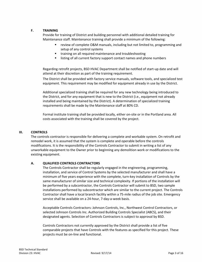
F. TRAINING
Provide for training of District and building personnel with additional detailed training for Maintenance staff. Maintenance training shall provide a minimum of the following:
review of complete O&M manuals, including but not limited to, programming and setup of any control systems
training on all required maintenance and troubleshooting listing of all current factory support contact names and phone numbers
Regarding retrofit projects, BSD HVAC Department shall be notified of start-up date and will attend at their discretion as part of the training requirement. The District shall be provided with factory service manuals, software tools, and specialized test equipment. This requirement may be modified for equipment already in use by the District.
Additional specialized training shall be required for any new technology being introduced to the District, and for any equipment that is new to the District (i.e., equipment not already installed and being maintained by the District). A determination of specialized training requirements shall be made by the Maintenance staff at 80% CD.
Formal institute training shall be provided locally, either on-site or in the Portland area. All costs associated with the training shall be covered by the project.
III. CONTROLS
The controls contractor is responsible for delivering a complete and workable system. On retrofit and remodel work, it is assumed that the system is complete and operable before the controls modifications. It is the responsibility of the Controls Contractor to submit in writing a list of any unworkable equipment to the Owner prior to beginning any demolition work or modifications to the existing equipment. A. QUALIFIED CONTROLS CONTRACTORS
The Controls Contractor shall be regularly engaged in the engineering, programming, installation, and service of Control Systems by the selected manufacturer and shall have a minimum of five years experience with the complete, turn-key installation of Controls by the same manufacturer of similar size and technical complexity. If portions of the installation will be performed by a subcontractor, the Controls Contractor will submit to BSD, two sample installations performed by subcontractor which are similar to the current project. The Controls Contractor shall have a local branch facility within a 75-mile radius of the job site. Emergency service shall be available on a 24-hour, 7-day-a-week basis.
Acceptable Controls Contractors: Johnson Controls, Inc., Northwest Control Contractors, or selected Johnson Controls Inc. Authorized Building Controls Specialist (ABCS), and their designated agents. Selection of Controls Contractors is subject to approval by BSD. Controls Contractors not currently approved by the District shall provide a list of five comparable projects that have Controls with the features as specified for this project. These projects must be on-line and functional.
BSD Technical Standard Division 23: HVAC Revised: 9/17/14 Page 3 of 16
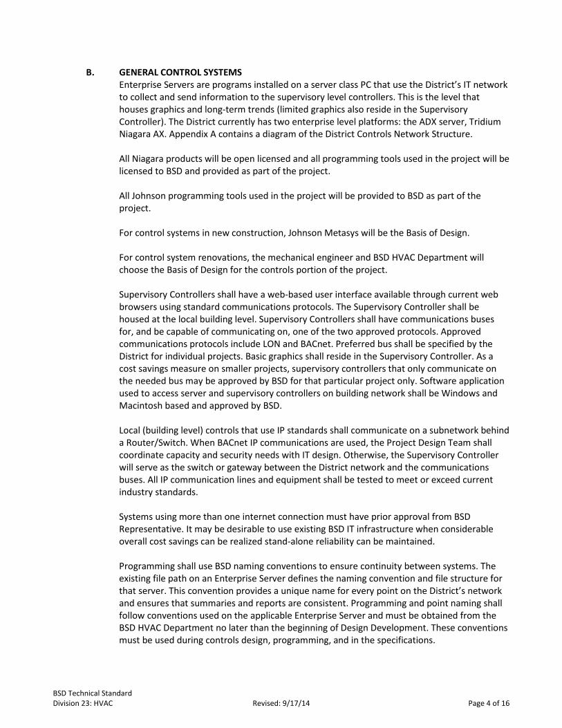
B. GENERAL CONTROL SYSTEMS Enterprise Servers are programs installed on a server class PC that use the District’s IT network to collect and send information to the supervisory level controllers. This is the level that houses graphics and long-term trends (limited graphics also reside in the Supervisory Controller). The District currently has two enterprise level platforms: the ADX server, Tridium Niagara AX. Appendix A contains a diagram of the District Controls Network Structure. All Niagara products will be open licensed and all programming tools used in the project will be licensed to BSD and provided as part of the project. All Johnson programming tools used in the project will be provided to BSD as part of the project. For control systems in new construction, Johnson Metasys will be the Basis of Design. For control system renovations, the mechanical engineer and BSD HVAC Department will choose the Basis of Design for the controls portion of the project. Supervisory Controllers shall have a web-based user interface available through current web browsers using standard communications protocols. The Supervisory Controller shall be housed at the local building level. Supervisory Controllers shall have communications buses for, and be capable of communicating on, one of the two approved protocols. Approved communications protocols include LON and BACnet. Preferred bus shall be specified by the District for individual projects. Basic graphics shall reside in the Supervisory Controller. As a cost savings measure on smaller projects, supervisory controllers that only communicate on the needed bus may be approved by BSD for that particular project only. Software application used to access server and supervisory controllers on building network shall be Windows and Macintosh based and approved by BSD. Local (building level) controls that use IP standards shall communicate on a subnetwork behind a Router/Switch. When BACnet IP communications are used, the Project Design Team shall coordinate capacity and security needs with IT design. Otherwise, the Supervisory Controller will serve as the switch or gateway between the District network and the communications buses. All IP communication lines and equipment shall be tested to meet or exceed current industry standards.
Systems using more than one internet connection must have prior approval from BSD Representative. It may be desirable to use existing BSD IT infrastructure when considerable overall cost savings can be realized stand-alone reliability can be maintained.
Programming shall use BSD naming conventions to ensure continuity between systems. The existing file path on an Enterprise Server defines the naming convention and file structure for that server. This convention provides a unique name for every point on the District’s network and ensures that summaries and reports are consistent. Programming and point naming shall follow conventions used on the applicable Enterprise Server and must be obtained from the BSD HVAC Department no later than the beginning of Design Development. These conventions must be used during controls design, programming, and in the specifications.
BSD Technical Standard Division 23: HVAC Revised: 9/17/14 Page 4 of 16

C. APPLICATION-SPECIFIC CONTROLLERS AND LOCAL CONTROL UNITS
Application-Specific Controllers are specialized Local Control Units and can include, but are not limited to, PLCs (programmable logic controllers), unitary controllers, manufacturers’ on-board controls, vendor devices, and other controls. The BSD prefers Application-Specific Controllers with standard (“canned”) sequences. Controllers requiring custom programming and complex sequences shall be avoided. The goal at each level of Application-Specific Controls is to provide the simplest most straightforward sequence, program, and system that will meet the District’s operational and maintenance needs, consistent with the District’s established energy standard. Where cost effective, design, and build each system with capacity for expansion to meet future operational needs. Local Control Units for HVAC equipment shall be factory installed. Local Control Units shall be by approved manufacturer. Controls by HVAC equipment manufacturer must be approved by BSD (see Appendix B) on a project-specific basis. Local Control Units shall use approved communication protocol. Preferred protocol is JCI MetasysBACnet. Other protocols shall be approved on a project-specific basis include: BACnet IP: BTL listed, BACnet MS/TP: Metasys Compliant, LON: Lonwork® Certified. Local Control Units shall operate as stand-alone controllers capable of performing specified control responsibilities independent of other controllers in the network. The District maintains the control system with in-house staff so programming should favor Application-Specific Controllers with standard sequences. All Application-Specific Controllers must be capable of remote programming over the District Enterprise network and all programs required will be installed, licensed to BSD, and BSD personnel will be trained on their use.
IV. HVAC SYSTEMS
A. GENERAL 1. Refrigerants The following refrigerants are acceptable for use in chillers and DX equipment as appropriate on District projects: R-410a, R-134a, R-404a, and R-407c. The District goal is to use the same refrigerant throughout each individual facility. Refrigerant selection for equipment over 20 tons will be finalized at 100% DD review with District Maintenance input.
2. Air Filters Air filters are required on all air handlers. MERV 8 (Farr 30/30), 2” pleated high efficiency filters or better required.
3. Life Cycle All HVAC systems should be designed around a 50-year life cycle. The Project Design Team must provide unbiased life-cycle costing as part of the evaluation process for any system requiring BSD approval. Replacement cost and equipment life must be based on industry accepted and recognized sources. HVAC systems cannot be accurately analyzed without defined setpoints and sequence of operation. HVAC systems must have setpoints and
BSD Technical Standard Division 23: HVAC Revised: 9/17/14 Page 5 of 16

sequence of operation defined at beginning of Design Development, prior to doing life-cycle cost comparison.
4. Air-Handling Equipment The BSD prefers air-handling equipment installed in penthouse spaces as opposed to being roof mounted. This will allow the opportunity to explore the use of alternate roof systems. Hot water or chilled water coils on rooftop air handlers may only be used with BSD approval. The entire system must be freeze protected to 10°F.
5. Load Calculations The Project Design Team shall provide HVAC load calculations and demonstrate that equipment is not oversized or undersized. Equipment shall be designed to accommodate load swings. Air handling (fan capacity) shall provide 110% of calculated design requirements. Equipment heating and cooling capacity for any single system should not exceed calculated design load by more than 10%. HVAC calculations will include both the maximum and minimum heat/cool loads. Energy efficiency shall be maintained down to 25% of maximum building load.
6. Redundancy Redundancy is desired in heating systems. Full redundancy in each system is not required; however, no single equipment failure should take the building out of its established operating parameters (such as a single boiler or pump).
7. Miscellaneous Airside economizers are required for all air handling equipment, regardless of size. Provide
necessary outside air, but no more than required. On systems of greater than 2,000 cfm (5 tons) design controls to dynamically vary outside air with occupancy.
Evaluate use of heat recovery ventilation on all systems larger than 2,000 cfm.
Any gas fired unit with a burner rating over 199,000 Btu shall have a fully modulating
burner with at least a 4:1 turndown ratio. Air handling units over 5,000 cfm shall have a method for reducing ventilation fan power
during light loads (i.e., VFD). Mixed air low limit required for all air handlers (even with gas heat).
Areas that regularly have occupancy scheduled outside of the schools operating hours
(e.g., summer office hours and auditoriums) shall be identified. Options that minimize energy use shall be evaluated using life-cycle costing.
All spaces with year-round cooling demand, such as computer rooms and data centers,
shall have their own dedicated system with airside economizer. Heat recovery opportunities will be evaluated for areas with more than 5 kW of equipment load.
Design Zone HVAC to minimize simultaneous heating and cooling. Where possible, design
with separate systems for interior and exterior zones. This will improve comfort and also
BSD Technical Standard Division 23: HVAC Revised: 9/17/14 Page 6 of 16

reduce the inherent need for simultaneous heating and cooling. Variable refrigerant flow systems should be designed and zoned per manufacturer’s recommendations.
Design for ASHRAE Standard 55 comfort envelope, which indicates 90% comfort in our
climate at a space temp of 70°F heating and 75°F cooling. Installed control set points should meet this standard.
Design shall allow easy maintenance, with unobstructed access to items requiring regular
maintenance. Installation must allow all access doors to fully open. All filters, valves, controls, sensors, motors, and bearings must be accessible. Minimize fan-powered Variable Air Volume (VAV) boxes. BSD approval required at beginning of DD.
Phase monitors and protection required for all 3-phase equipment larger than 5 hp.
B. DUCTWORK
Ductwork shall be installed to current industry recommended standards.
1. Flex Duct Flex duct shall be limited to a maximum length of 6’-0”.
2. Duct Board Duct board shall not be used on new installations. During remodels if the ductwork being modified is duct board, then removal and replacement of the duct board is required in effected area.
C. PIPING AND VALVE SCHEDULE
Hydronic Piping No black iron piping below 3ӯ. Threaded pipe and fittings shall only be used at terminations. No threaded fittings or drains shall be located above hard lids. See Division 22 Plumbing for domestic water, sanitary and natural gas connections.
PIPING SCHEDULE Service Size Location Material Hydronic and Chilled Water Systems
Through 2”Ø All Copper-Type “L” or Better, Soldered Fttgs. ProPress fittings allowed where accessible for maintenance
2-1/2”Ø All Copper-Type “L” or Better, Brazed Fttgs
3ӯ And Larger All Black Steel w/ Welded or Flanged Fttgs
All Ø’s, Two foot maximum length
All Flex Connectors, Stainless Steel, or Copper, Two foot maximum length
BSD Technical Standard Division 23: HVAC Revised: 9/17/14 Page 7 of 16

VALVE SCHEDULE System Service Valve Type Size Material Hydronic and Chilled Water Systems
Shut-Off, Throttling, Drain
Ball, Full-Port All Bronze
Shut-Off, Throttling Butterfly 3ӯ Or Larger
Cast Iron or Bronze
Throttling Globe All Bronze
D. MOTORS AND VARIABLE FREQUENCY DRIVES (VFD) All HVAC fan and pump motors that are 1/6th horsepower and greater shall provide status
signal to the building management system through use of a current sensing device to verify that the motor is running.
All field installed VFDs shall be manufactured by ABB or District approved equal. All VFDs
other than ABB will require additional training. All variable frequency drives (VFD) shall be rated for HVAC service. Mount VFDs on the
equipment being controlled (within sight of) and served by the same disconnect as the equipment it serves.
Bypasses shall not be used on VAV HVAC air handling equipment. Bypasses are acceptable
for use on pumps. Factory installed VFDs are acceptable when provided on package equipment if thoroughly
covered in manufacturer’s service manual and fully covered by the package equipment manufacturer’s warranty.
E. VARIABLE AIR VOLUME (VAV)
VAV is the most commonly used system in the District. VAV is not the only system allowed, but it is the only one that has been used enough in the BSD to be a valid point of comparison. All other proposed systems should be compared to VAV with the parameters found in Appendix C. All energy modeling and cost comparison should use VAV as the baseline.
F. VARIABLE VOLUME BY TEMPERATURE (VVT)
VVT shall only be used with BSD approval. BSD approval required at beginning of DD. Review and evaluation based on comparison to VAV system.
VVT should not be used with more than three zones. Must be minimal disparity between zones if VVT is to be considered. Both the heating load
and the cooling load must be similar in all VVT zones.
G. DISPLACEMENT VENTILATION Displacement ventilation shall only be used with BSD approval. BSD approval required at beginning of DD. Review and approval shall be based on comparison to VAV system.
BSD Technical Standard Division 23: HVAC Revised: 9/17/14 Page 8 of 16

H. SPLIT SYSTEMS Condensing units on grade are discouraged. For approved systems: All condensing units must be isolated from sight. Noise generated
by the condensing unit must be controlled so that sound levels are not increased in instructional areas when the condensing unit is running. Condensing units shall be protected from vandalism.
Limit split systems to the following areas, with BSD approval. BSD approval required at
beginning of DD. Review and evaluation based on comparison to single-zone rooftop air handler with economizer.
Elevator mechanical rooms Server rooms Electrical rooms Retrofit computer labs Office portables or modular buildings with multiple zones
Areas with occupancy should be provided with independent ventilation such as a heat
recovery ventilator. Mechanical rooms should have an exhaust fan with thermostatic control.
All split systems must have control strategy specified at design and be integrated into the
total system.
Gravity feed condensate drains are required on all indoor units. Condensate evaporators and pumps are not acceptable.
I. DATA FRAME ROOMS
Provide engineered HVAC system for MDF (main data frame) and IDF (intermediate data frame) server rooms. Design shall provide outside air intake, adequate air changes per hour, and cooling to meet anticipated equipment load and maintain temperatures below 80°F on a Design Day. Data frame room HVAC systems shall be thermostatically controlled with cooling and ventilation available 24 hours, seven days a week. Data frame rooms that are designed with exhaust only systems must provide outside air intake and a chase adequate to allow future addition of mechanical cooling.
J. UNIT VENTILATORS
Avoid unit ventilators and Package Terminal Air Conditioning (PTAC) units in new construction. BSD approval required at beginning of DD. Review and evaluation should be based on comparison to single-zone rooftop air handler with economizer and/or fin tube as appropriate.
Univents shall not be approved for use in new classroom construction.
Univents may be approved for use as replacement for existing univents in remodels and
retrofits. Univents may be approved for use in new construction for corridors and lobbies (compare to fin tube).
Valve control only. No face and bypass heating control.
BSD Technical Standard Division 23: HVAC Revised: 9/17/14 Page 9 of 16

K. MULTI-ZONE AIR HANDLERS Multi-zone air handlers are not approved for use in the Beaverton School District.
L. RESIDENTIAL FURNACE HEATING AND COOLING
Residential furnace heating and cooling is not approved for use in the Beaverton School District.
M. SINGLE-ZONE ROOFTOP SYSTEM
Must have an airside economizer Any unit larger than 2,000 cfm shall have a fully modulating outside air damper.
All single-zone units over five tons shall have demand ventilation.
Any gas fired unit with a burner rating over 199,000 Btu shall have a modulating burner
with at least a 4:1 turndown ratio. Large units, such as high school gyms, should have a method for reducing ventilation fan
power during light loads (e.g., Variable Frequency Drive (VFD)).
N. HEAT PUMPS Must have an airside economizer.
Systems must have control strategy specified at design and be integrated into the total
system. Special care should be taken to minimize use of electrical resistance heating and associated demand charges.
Heat pump systems over five tons should have gas heat as supplemental heat source.
Due to limited air conditioning season, heat pump efficiency shall be evaluated on Heating
Seasonal Performance Factor (HSPF).
O. EXHAUST FANS 1. Kiln Rooms Kilns shall not be located in conditioned space. Provide adequate ventilation to maintain space temperature at or below 80°F while the kiln is being fired with the kiln room door closed. Kiln room ventilation shall be designed with high exhaust and low make-up air intake. Exhaust fan shall be brought on at 80°F regardless of building HVAC schedules. 2. Restrooms Exhaust fans for single stall restrooms shall be controlled by the lighting occupancy sensors. Multiple stall restrooms shall have exhaust fans controlled through the building management system (BMS). The exhaust fan operation shall be scheduled to start and stop with the HVAC for that portion of the building. The exhaust fan shall be capable of being scheduled or overridden to operate independent of the HVAC systems operation.
BSD Technical Standard Division 23: HVAC Revised: 9/17/14 Page 10 of 16

V. CENTRAL PLANTS A. BOILERS
1. General Requirements (Applies to New Construction and Remodels) Natural gas fired only. Boiler Systems must be capable of stand-alone operation. No domestic hot water (DHW) on heating boiler systems. Fully redundant pumping systems. Hydronic heating systems are preferred. Chemical water treatment required for all heating boilers.
New construction Hydronic heating systems are preferred No distributed pumping. Central pump with VFD and full redundancy is required.
2. Heating Boilers Fully modulating burner control with a minimum 4:1 turndown ratio. For systems without rooftop gas packs, boiler plants should be designed N+1 to provide
redundancy. Systems using condensing boilers should be designed around the manufacturer’s
recommendations to provide the best life-cycle cost. Constant flow loops may need to be of the primary secondary type to operate the boiler in its efficiency range.
Steam boilers will not be installed in new heating distribution systems. Condensate treatment required for all condensing boilers. Above 4 MMBtu total capacity, cast iron sectional boiler(s) with a condensing boiler as
“pony” boiler to increase seasonal efficiency is preferred. Control panels on Condensing boilers must be integrated into the BAS system. Sequencing
controllers shall only be used for installation with multiple boilers. Multiple boilers shall have a manufacturer’s approved sequencing panel with dedicated outside air sensor for stand-alone operation. Single boilers will have onboard modulating control. Boiler controls and sequence of operation require Owner approval no later than 100% Design Development (DD).
3. Domestic Hot Water Central system in boiler room vs. distributed system shall be determined by
site-specific comparison. Comparison should be based on life-cycle costing. Specific retrofit and remodeling application may require life-cycle comparison of electric vs. natural gas vs. tankless demand.
District preferred systems: Commercial 199,000 Btu high-efficiency natural gas water heaters with a 90+ rating, or condensing hot water boiler with storage tank. For large systems provide life-cycle cost comparison of multiple 199,000 Btu water heaters vs. single condensing boiler with storage tank.
BSD Technical Standard Division 23: HVAC Revised: 9/17/14 Page 11 of 16

B. CHILLERS All Projects Chilled water coils on rooftop air handlers shall be used only with BSD approval and entire
system must be freeze protected to 10°F. BSD approval required at beginning of DD.
Life-cycle costing should be used for system comparisons if chilled water systems are being considered as an option during design. Only use chillers if it “pays” through life-cycle costing. Comparison should include Direct Expansion (DX) (as baseline) vs. Air Cooled Chiller vs. Water Cooled Chiller vs. Chiller with Water-Side Economizer.
No chilled water systems under 100 tons. Always consider chilled water system in multi-story buildings with high ratio of interior to
exterior zones. Because of limited summer run-time, emphasize turn down ratio and Integrated Part Load
Value (IPLV) over Energy Efficiency Rating (EER). Refrigerants: All systems over five tons must use a refrigerant approved by BSD HVAC
Department. Refrigerant R-410a is acceptable for small DX equipment (20 tons or less). Ground fault protection for equipment is required on systems over 50 tons.
VI. APPENDICES
BSD Technical Standard Division 23: HVAC Revised: 9/17/14 Page 12 of 16

APPENDIX A Controls Network Structure
District IT Network
IP Address
ADX Server
ROUTER
NAE
BACnet IP Devices
Air Handler
Chiller
Local Bus & Devices
LON Devices
N2 Devices
N1
N2 Bus
JCI Serial BACnet
LON Bus
HVAC Net
IT Net
N1 BACnet Bus
Enterprise Server
BSD Technical Standard Division 23: HVAC Revised: 9/17/14 Page 13 of 16

APPENDIX B VAV Design Parameters
Size to:
Heating: 70 +/- 1°F Cooling: 75 +/- 1°F Economizer Return Air (RA)> Outside Air (OSA) > 50°F Heating Design Day 17°F o For hydronic system (hot water reset = 40°F/140°F) o Preferred system: Gas pack Air Handling Unit (AHU) (17°F HDD) and Hydronic VAV
(40°F/140°F) o Gas pack used for warm up and Night Low Limit (NLL) only. o Rooftop units over 200,000 Btu = modulating burner 4:1 turndown minimum
Match zone loads to avoid simultaneous cooling and heating. Design with separate interior and
perimeter zones. Airside economizers required for all air handling equipment. Use demand control ventilation when required by Oregon code and for spaces with large
population diversity. The method chosen should limit outside air to a reasonable default set point in the event of a sensor going out of calibration.
Heat recovery ventilation recommended for areas with greater than 50% minimum outside air. BSD approval required for any system requiring greater than 50% minimum outside air.
Fume hoods and exhaust fans need tempering of make up air. Air balance must be addressed during design. Design minimum air setting for VAV boxes to balance at less than 50% of cooling cubic feet per minute (cfm).
Floating-point valve actuators shall not be used with VAV systems. Self-balancing ball valves are preferred.
All rooftop VAV systems with gas packs shall be designed and programmed so that the gas heat is used only for night low limit, morning warm-up, and provide backup during a boiler failure.
There are three modes of control for each rooftop unit. A separate Proportional Integral Derivative (PID) control loop shall be required for each mode. The modes are heating mode, ventilate, and mechanical cooling mode.
Building static control should be accomplished by controlling return fans to track supply fans. Units with exhaust fan instead of a return fan should have the fan controlled as recommended by the unit manufacturer.
BSD Technical Standard Division 23: HVAC Revised: 9/17/14 Page 14 of 16

APPENDIX C
VAV Sequence of Operations
Gas-Fired, DX Cooled, Variable Air Volume RTU with VAV Exhaust Fan Sequence of Operations
All values in parentheses are initial settings and shall be user-adjustable from the graphical and text user interfaces.
Unoccupied
Fans off, heat off, DX cooling off, and dampers indexed to full recirculation.
Unoccupied Low Limit The unoccupied low limit shall be accomplished by both the RTU gas furnace and the terminal unit hot water re-heat (boiler operation). The system shall continuously monitor the lowest VAV terminal unit zone temperature associated with the VAV RTU. When the lowest zone temperature drops below the RTU night low limit set point (55°F), the RTU fan will start and heating staged to full heating. All VAVs shall be indexed to control to current air flow set point to ensure proper flow across RTU heat exchanger. RTU dampers shall remain in full recirculation. Units shall heat until lowest zone is five degrees above RTU night low limit set point. Subject to the boiler outside air lockout temperature (65°F), when the RTU fan is operational in unoccupied low limit and there is a call for heating at any VAV terminal unit served by that unit, the boiler system will be enabled.
Warm-up Fan runs continuously. Based on the average zone temperature, the optimum start/stop function starts the RTU in warm-up mode so that the average zone temperature will reach set point at the scheduled occupancy time. The RTU set point shall be the calculated average of all individual zone temperature set points for the VAV terminal units served by the RTU. During warm-up, the dampers shall remain in full circulation and shall cycle to minimum outside/CO2/economizer control at occupancy time regardless of average zone temperature. The boiler system and terminal units shall be enabled for warm-up mode at the same time as the first RTU starts for warm-up.
Occupied
The occupied sequence of operations for the gas-fired heat, DX cooled, Roof Top Units shall consist of three separate control modes: heating, ventilation and mechanical cooling modes. All modes are active continuously during occupied mode subject to individual mode limits. This will allow heating and ventilation mode to be in effect at the same time and ventilation and mechanical cooling to be in effect at the same time. Based on mode limits, heating and mechanical cooling modes should not be in effect at the same time.
Fan runs continuously. Modulate gas furnace, economizer dampers, and mechanical cooling to control zone temperatures per the following operating modes.
BSD Technical Standard Division 23: HVAC Revised: 9/17/14 Page 15 of 16

Heating Mode
The gas furnace shall be locked out above an outside air temperature of (65) °F. Gas furnace is disabled unless average zone temperature falls below RTU heating/warm-up set point.
Ventilation Mode
The mixed air control shall modulate to control the following, in the priority order listed: Mixed air low limit set point (45°F) to prevent comfort problems. Mixed air high limit set point (85°F) to prevent excess cooling load. CO2 high limit set point (800–1200 ppm reset). Discharge air temperature set point (reset on outside air) subject to outside air temperature
lockout. If the outside air is above return air temperature (2 degree dead band), modulate dampers to minimum air flow.
Minimum ventilation air flow rate: (350 cfm).
The discharge air set point shall be reset from (55)°F at (70)°F outside air to (65)°F at (50)°F based on an outside air temperature reset. If the outside air temperature is above the return air temperature the mixed air should be at minimum position as allowed by the minimum outside air setting and CO2 level.
Mechanical Cooling Mode
DX cooling shall be locked out below an outside air temperature of (60) °F. The system shall continuously monitor the highest VAV terminal unit zone temperature associated with the VAV RTU. The RTU will modulate the mechanical cooling to maintain the highest VAV terminal unit temperature at the RTU cooling temperature set point. The computer room unit thermostat should not be allowed to participate in any “voting” for average or maximum zone temperature.
Fan Control
The RTU supply fan shall control to a duct static pressure set point. The system shall continuously monitor the maximum VAV terminal unit damper position and reset the duct static pressure from 0.5” to 1.5” so the maximum damper position is continuously at 95%. The exhaust fan shall not be energized unless the dampers are positioned at greater than 50%. When operating, the RTU exhaust fan shall control to the building static pressure set point (0.03”).
BSD Technical Standard Division 23: HVAC Revised: 9/17/14 Page 16 of 16