Embed Size (px)
Citation preview
INSTRINSICALLY SAFEMULTIFUNCTION CALIBRATOR
User GuideApplies for Main Firmware version 1.90
Dear user,
We have made every effort to ensure the accuracy of the contents of this manual.Should any errors be detected, we would greatly appreciate to receive suggestionsto improve the quality of the contents of this manual.
The above not withstanding, we can assume no responsibility for any errors in thismanual or their eventual consequences.
We reserve rights to make modifications to this manual without any further notice.
For more detailed technical data about the MC5-IS Multifunction Calibrator, pleasecontact the manufacturer.
© Copyright 2002, 2003, 2006, 2007, 2008BEAMEX OY ABRistisuonraitti 10FIN-68600 PietarsaariFINLANDTel +358 - 10 - 5505000Fax +358 - 10 - 5505404E-mail: [email protected]
[email protected]: http://www.beamex.com
8823000 / UEMC5-IS / 002788

Contents
TrademarksQCAL® is a registered trademark owned by Oy Beamex Ab.HART® is a registered trademark of the HART Communication Foundation.
Any use of the word “HART” hereafter inthis document implies the registered trademark.
Other trademarks are property of their respective owners.
Contents
Contents
Part A, General
MC5-IS’ Modularity and Options 23Hardware Modules/Options ................. 23
Other Connectable Devices ........... 24Firmware Options ................................. 24
Safety 25Ex Information and Approvals .............. 25Safety Precautions and Warnings ....... 26
General Warnings .......................... 26Warnings Concerning the useof Electrical Modules (E and ET) .... 27General Warnings ConcerningPressure Measurement .................. 27Warnings ConcerningHigh Pressure ................................ 28
Service 29Firmware Update ................................. 29Recalibrating MC5-IS ........................... 29The Battery Charger ............................ 29Cleaning MC5-IS .................................. 30
Cleaning the Contacts ofthe Internal ReferenceJunction Module ............................. 30
Introduction 2About This Manual ................................. 2
Typographical Conventions .............. 3Unpacking and Inspection ..................... 3
MC5-IS Hardware 4Operational Sections andConnections ........................................... 4
The Upper Panel .............................. 5The RS232 Connector onthe Left Side of MC5-IS .................... 6The Front Panel ................................ 6
Memory .................................................. 9Batteries ............................................... 10
About the Charger andthe Charging Procedure ................. 11Removing/Replacingthe Battery Pack ............................. 12
Support for Table Top Use ................... 13The Wrist Strap andthe Neck Support Strap ........................ 13
MC5-IS Firmware 14General Description ............................. 14
Startup Procedure .......................... 14Basic Mode ..................................... 15Maintenance ................................... 15Calibration Mode ............................ 15Help Function ................................. 16
The User Interface ............................... 17The Status Bar ................................ 17The Function Key Bar .................... 18Menus ............................................. 18The Display Area ............................ 19
Contents
Part B, Startup and Basic Operation
Starting MC5-IS 32Startup Procedure ................................ 32Basic Mode, Defined ............................ 33
Measuring 35Pressure Measurement ........................ 37
Using Internal Modules .................. 37Using External Modules ................. 37Zeroing a Pressure Module ............ 38
Current Measurement .......................... 39Voltage Measurement .......................... 40
Measuring Low Voltages ................ 40Measuring Voltages up to ±30 V .... 41
Resistance Measurement .................... 42Switch State Sensing ........................... 43Limit Switch Test .................................. 44
Performing the Limit Switch Test .... 44Frequency Measurement ..................... 46Pulse Counting .................................... 47RTD Measurement (Temperature) ....... 48ThermocoupleMeasurement (Temperature) ............... 49
Internal Reference Junction ........... 49External Reference Junction .......... 49
Special Measurements 51Mathematical Special Measurements .. 52
Minimum value ............................... 52Maximum value .............................. 52Min/Max value ................................ 52Rate of Change .............................. 52Special Filtering and Resolution ..... 53Deviation Measurement ................. 53
Special Measurements UsingTwo Ports Simultaneously .................... 54
Difference Measurement ................ 54Redundant Measurement ............... 55
Generating/Simulating 56General ................................................ 56
Changing the Value ofthe Generated/Simulated Signal .... 57
Current Sink ......................................... 58Using the ET module’soutput terminals .............................. 58Using the E module’soutput terminals .............................. 58
Voltage Generation .............................. 60Generating Voltagesbetween +10 V and -2.5 V .............. 60Low Voltage Generation ................. 60
Frequency Generation ......................... 62Pulse Generation ................................. 63RTD and Resistance Simulation .......... 64Thermocouple Simulation .................... 65
Internal Reference Junction ........... 65External Reference Junction .......... 65
Special Generations 67Opening the Step or RampConfiguration Window ......................... 67Stepping ............................................... 68Ramping ............................................... 69
Alarm Limit Settings 71
Contents
Configuring the Calibrator 74Settings ................................................ 74Setting Time and Date ......................... 76
Advanced Utilities 77Display Mode Settings ......................... 77
Scaling ............................................ 78Displaying Values in Percentage .... 79Displaying Error Values .................. 79
Transmitter/Switch Simulation ............. 80Transmitter Simulation ................... 81Switch Simulation ........................... 82
Data Logging ........................................ 83General ........................................... 83Configuring ..................................... 83Starting the Data Log...................... 84Viewing the Results ........................ 85Transferring the Results toa Personal Computer ..................... 85
Part C, Advanced Operation and Configurations
Additional Information 86Things to Consider whenMeasuring Pressure ............................. 87
General ........................................... 87Pressure Type ................................ 87Pressure Modules andtheir Naming Conventions .............. 88Square Rooting .............................. 88
ThermocoupleMeasurement/Simulation,Connections and Troubleshooting ....... 89
Internal Reference Junction ........... 89External Reference Junction .......... 90Error situations ............................... 92
Resistance andRTD Measurement, Connections ......... 93
4-wire System................................. 933-wire System................................. 93Using a Compensation Loop .......... 942-wire System................................. 94
Current Measurement Parallelto a Test Diode, Connections ............... 95Parallel Functions in MC5-IS ............... 96
Contents
Part D, Calibration
General 98Phases of Instrument Calibration ........ 99
As Found Calibration .................... 100Adjustment ................................... 100As Left Calibration ........................ 101
Required Modules for DifferentInput/Output Signal Combinations ..... 102
Calibrating an Instrument 104Selecting the Instrumentto Be Calibrated ................................. 104The Instrument Window ..................... 105A Calibration ProcedureUsing MC5-IS ..................................... 106
About Automatic Calibration ......... 108About Manual Calibration ............. 108
Examples of Instrument Calibration ... 109Pressure Transmitters .................. 110Temperature Sensors ................... 112Temperature Indicators andRecorders ..................................... 114Electrical Limit Switches ............... 116
MC5-IS’ Support forInstrument Adjustment ....................... 118
Maintaining MC5-IS’Instrument Database 119
Adding New Instruments .................... 119Editing Instrument Data ..................... 120
General Data Page....................... 120Instrument Input Page .................. 121Instrument Output Page ............... 121Calibration Settings Page ............. 122Calibration Instructions Page ....... 123
Deleting Instruments .......................... 123
Viewing Calibration Results 124Calibration Result Windows ............... 125
How to Choose WhichCalibration Run is Viewed ............ 125
Deleting Calibration Results .............. 125
Appendix 1,User Guide forMC5 HART Option 128
Appendix 2,Technical Data 142
Appendix 3,Quick Guide forthe MC5 Datalog Viewer 148
Appendix 4,Safety information 152
Appendix 5,Index 154
Feedback form
Feedback
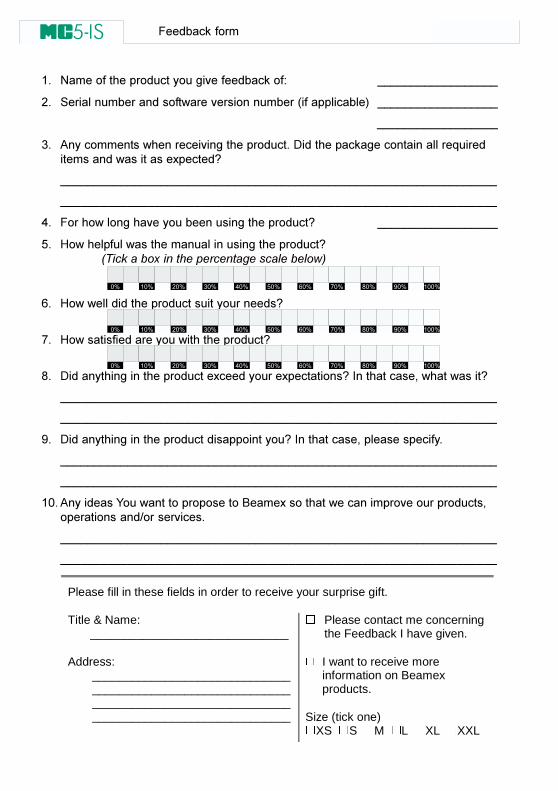
We want to improve our products and services constantly. There-fore we’d like to know Your opinion of the product You use. Pleasespend a moment of Your valuable time in filling this form. All re-spondents will receive a surprise gift in return.
Certain questions can be answered immediately after receiving theproduct. Others require some use of the product before You areable to answer them. The best way to fill the form is to answer theitems as it applies, and send the form to us when all items areanswered. There are however no definite restricitions; fill in the formwhen you feel like it (all items need not be answered). Then send itto Beamex using one of the possibilities listed below.
Mail: Beamex Oy AbQuality FeedbackRistisuonraitti 10FIN-68600 PietarsaariFINLAND
Fax +358 - 10 - 5505404Only the next page need to be faxed to us.
Internet: http://www.beamex.comA similar form is available as a web page
E-mail: [email protected] to the numbered items on the nextpage in Your e-mail message.
�����������
.� /��������������������������������+ 000000000000000000
1� 2��������������������������������������&������������' 000000000000000000
000000000000000000
3� ��������������������������������������4����������������������������"��������������������������)������5
00000000000000000000000000000000000000000000000000000000000000000
00000000000000000000000000000000000000000000000000000000000000000
6� ���������������������������������������5 000000000000000000
7� 8�������������������������������������������5���������������� ����������������������������������!
9� 8������������������������������������5
:� 8���������������������������������5
;� 4���������������������������)����������)���������5�,�����������$������������5
00000000000000000000000000000000000000000000000000000000000000000
00000000000000000000000000000000000000000000000000000000000000000
<� 4��������������������������������������5�,�����������$���������������
00000000000000000000000000000000000000000000000000000000000000000
00000000000000000000000000000000000000000000000000000000000000000
.=� ���������������������������(����)��������������������������������$������������>�����������
00000000000000000000000000000000000000000000000000000000000000000
00000000000000000000000000000000000000000000000000000000000000000
Please fill in these fields in order to receive your surprise gift.
Title & Name: ______________________________
Address: ________________________________________________________________________________________________________________________
� Please contact me concerningthe Feedback I have given.
� I want to receive moreinformation on Beamexproducts.
Size (tick one)�XS �S �M �L �XL �XXL
� � � � � � � � � � � � � � � � � � � � � � � � � � � � � � �
� � � � � � � � � � � � � � � � � � � � � � � � � � � � � � �
� � � � � � � � � � � � � � � � � � � � � � � � � � � � � � �

General
Things discussed in Part A:
••••• An introduction to what MC5-IS isand what the parts of this UserGuide concentrate on.
••••• A general description of MC5-IS’hardware.
••••• A general description of MC5-IS’firmware.
••••• The modularity and options ofMC5-IS.
••••• Safety precautions and warnings.••••• Briefly about how to service
MC5-IS.
2
General
Introduction
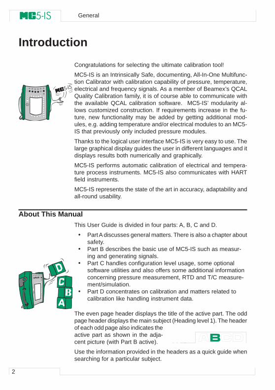
Congratulations for selecting the ultimate calibration tool!
MC5-IS is an Intrinsically Safe, documenting, All-In-One Multifunc-tion Calibrator with calibration capability of pressure, temperature,electrical and frequency signals. As a member of Beamex’s QCALQuality Calibration family, it is of course able to communicate withthe available QCAL calibration software. MC5-IS’ modularity al-lows customized construction. If requirements increase in the fu-ture, new functionality may be added by getting additional mod-ules, e.g. adding temperature and/or electrical modules to an MC5-IS that previously only included pressure modules.
Thanks to the logical user interface MC5-IS is very easy to use. Thelarge graphical display guides the user in different languages and itdisplays results both numerically and graphically.
MC5-IS performs automatic calibration of electrical and tempera-ture process instruments. MC5-IS also communicates with HARTfield instruments.
MC5-IS represents the state of the art in accuracy, adaptability andall-round usability.
About This ManualThis User Guide is divided in four parts: A, B, C and D.
• Part A discusses general matters. There is also a chapter aboutsafety.
• Part B describes the basic use of MC5-IS such as measur-ing and generating signals.
• Part C handles configuration level usage, some optionalsoftware utilities and also offers some additional informationconcerning pressure measurement, RTD and T/C measure-ment/simulation.
• Part D concentrates on calibration and matters related tocalibration like handling instrument data.
The even page header displays the title of the active part. The oddpage header displays the main subject (Heading level 1). The headerof each odd page also indicates theactive part as shown in the adja-cent picture (with Part B active).
Use the information provided in the headers as a quick guide whensearching for a particular subject.
3
Typographical ConventionsAll examples of user interface texts are printed using 8 pt ArialBlack, e.g.
Selected port: ET: TCi(mea)
All front panel texts (fixed texts on MC5-IS’ cover) are printedusing 8 pt Eurostile, e.g.
Connectors marked T/C, Low V
Function and Menu keys are often referred to using both the keyname in 8 pt Eurostile and the corresponding text (function)displayed on the screen in 8 pt Arial Black, e.g.
Function key D/Menu
Unpacking and InspectionAt the factory each new MC5-IS passes a careful inspection. It shouldbe free of scrapes and scratches and in proper operation orderupon receipt. The receiver should, however, inspect the unit for anydamage that may have occurred during transit. If there are signs ofobvious mechanical damage, package contents are incomplete, orthe instrument does not operate according to specifications, con-tact the purchasing sales office as soon as possible. The standardaccessories are as follows: • Calibration Certificate• This User Guide and a leaflet entitled “Safety Information for Beamex
MC5-IS Intrinsically Safe Multifunction Calibrator”• Warranty Card• Battery Pack, NiMH• Charger for the Battery Pack• Computer communication cable• If any internal pressure modules are present:
A pressure hose set• If the E module is present: Two test leads and clips• If the ET module is present: Four additional test leads and two clips
For a description of available hardware and software options, seeMC5-IS’ Modularity and Options on page 23.
If you have to return the instrument to the factory for any reason,use the original packing whenever possible. Include a detailed de-scription of the reason for the return.
Warning:
The accessory polyurethane hose supplied with the calibratoris rated to the maximum pressure of 20 bar at 21°C (290 psi at70°F). Applying higher pressure can be hazardous.
Introduction
4
General
MC5-IS Hardware
General features:
• IP65 water/dust proof case (EN60529)Battery pack IP30.
• Integrated impact protectors• Both a wrist strap and a neck support strap• A support for using the calibrator on the table• Operating temperature: -10 … +50 °C (14 … 122 °F).
+10 … +35 °C (50 … 95 °F) when charging the batteries.• Storage temperature: -20 … +60 °C (-4 … 140 °F).
Note: The stickers and the batteries may be affected whenstoring longer periods in extreme conditions.
• Humidity: 0 … 80 %RH
More comprehensive specifications are available in Appendix 2.
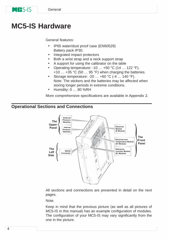
Operational Sections and Connections
All sections and connections are presented in detail on the nextpages.
Note.
Keep in mind that the previous picture (as well as all pictures ofMC5-IS in this manual) has an example configuration of modules.The configuration of your MC5-IS may vary significantly from theone in the picture.
� � � � � � � � � � � � �� � � � �
� � � � � � � � � � � � �� � � � �
� � � � � �� � � � � � �
� � � � � � � � � � � � � � �� � � � � � � � � � � � � � � � � �� � � � � � � � � � �
� � � � � � � � � � �� � � � � � � � � � � � �� � � � � � � � � �
� � � � � � � � � �� � � � �� � � � � � � � � �
� � �! � � � � � � � �
� � �" � � � �� � � �
� � �# � � � � � � �
5
The Upper PanelThe upper panel has 5 places for the following modules/connec-tors:
External Pressure ModulesMC5-IS has a connector for External Pressure Modules (EXTs). Theconnector is located on the right hand side of the upper panel andis marked with PX1 in a sticker on the upper panel.
Internal Pressure ModulesUp to three Internal Pressure Modules may be installed in MC5-IS.One of them may be an internal barometric module.
The connectors for Internal Pressure modules start from the sec-ond connector on the left. The possible Barometric Module is al-ways located as second from right and it measures the barometricpressure through a connection in the back panel of MC5-IS. Nor-mally nothing need to connected to the barometric pressure module’sconnector.
Internal pressure modules are marked with P1 … P3.
The recommended pressure medium for all internal pressure mod-ules is clean air. Clean non-corrosive liquids may optionally be usedin modules with a measuring range of 20 bar/300 psi or more. Avoidspilling liquid on MC5-IS when connecting/disconnecting pressurehoses to/from pressure modules.
To avoid damaging the calibrator, use hand tightening only whenconnecting the pressure measurement hoses (max. torque 5 Nm,approx. 3.6 lbf ft). If the use of tools is required to secure the con-nection (typically pressure modules with a pressure range higherthan 20 bar), apply the counterforce with a spanner on the connec-tor body’s hexagonal part.
The overpressure protection of the internal pressure modules ventsto the back of the calibrator. Remember to be cautious when work-ing with pressure and pressure modules. See also chapters Safetyon page 25 and Safety Precautions and Warnings on page 26.
MC5-IS Hardware
6
General
The RS232 Connector on the Left Side of MC5-ISThe RS232 connector may be used when connecting to a serialport in a PC. The PC may have a calibration software capable ofcommunicating with MC5-IS or, e.g. a software that reads data log-ging results in MC5-IS and transfers them to a PC.
Warning!
Use only cables provided by Beamex when connecting MC5-ISto a PC.
The Front PanelThe front panel has several sections. Some of them are pointed outwith a callout in the picture of Operational Sections and Connec-tions, and some of them not (e.g. display and keyboard). The oneswith a callout are discussed first in the following paragraphs.
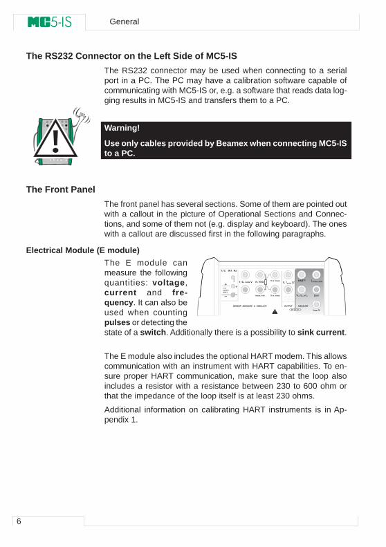
Electrical Module (E module)The E module canmeasure the followingquantities: voltage,current and fre-quency. It can also beused when countingpulses or detecting thestate of a switch. Additionally there is a possibility to sink current.
The E module also includes the optional HART modem. This allowscommunication with an instrument with HART capabilities. To en-sure proper HART communication, make sure that the loop alsoincludes a resistor with a resistance between 230 to 600 ohm orthat the impedance of the loop itself is at least 230 ohms.
Additional information on calibrating HART instruments is in Ap-pendix 1.
� � � � � � � � �� � � � � � � � � � � � � �
� � � � � � � �
� � � � � � � � � � �� � � �
� � �
� � � �
� � �
� � � � � � �� � �
� � �
� � � � � � � � � � � �
� � � � � � � � � � � � � � � � � � � � � � � � � �
� � � � � � � �
� � � � � ! � � �
� " � � � � ! # � � $
� � � �
$ � � % �
& � � '
! � � � � � �
( � � � � � �� � � � � � � �
7
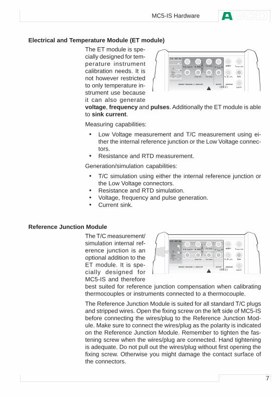
Electrical and Temperature Module (ET module)The ET module is spe-cially designed for tem-perature instrumentcalibration needs. It isnot however restrictedto only temperature in-strument use becauseit can also generatevoltage, frequency and pulses. Additionally the ET module is ableto sink current. Measuring capabilities:
• Low Voltage measurement and T/C measurement using ei-ther the internal reference junction or the Low Voltage connec-tors.
• Resistance and RTD measurement.
Generation/simulation capabilities:
• T/C simulation using either the internal reference junction orthe Low Voltage connectors.
• Resistance and RTD simulation.• Voltage, frequency and pulse generation.• Current sink.
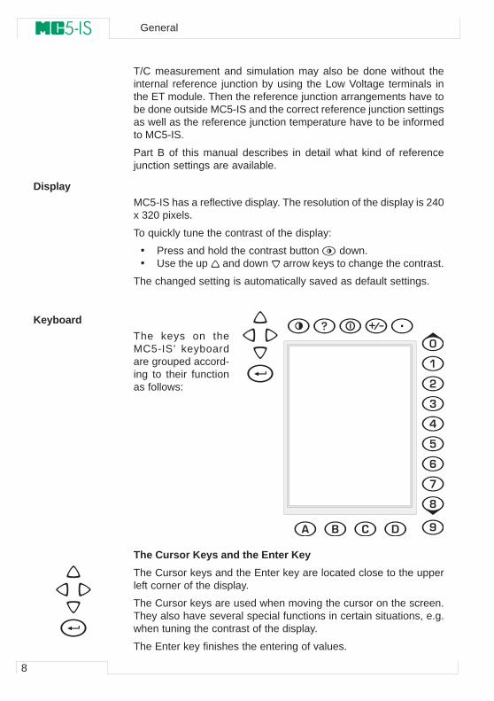
Reference Junction ModuleThe T/C measurement/simulation internal ref-erence junction is anoptional addition to theET module. It is spe-cially designed forMC5-IS and thereforebest suited for reference junction compensation when calibratingthermocouples or instruments connected to a thermocouple.
The Reference Junction Module is suited for all standard T/C plugsand stripped wires. Open the fixing screw on the left side of MC5-ISbefore connecting the wires/plug to the Reference Junction Mod-ule. Make sure to connect the wires/plug as the polarity is indicatedon the Reference Junction Module. Remember to tighten the fas-tening screw when the wires/plug are connected. Hand tighteningis adequate. Do not pull out the wires/plug without first opening thefixing screw. Otherwise you might damage the contact surface ofthe connectors.
� � � � � � � � �� � � � � � � � � � � � � �
� � � � � � � �
� � � � � � � � � � �� � � �
� � �
� � � �
� � �
� � � � � � �� � �
� � �
� � � � � � � � � � � �
� � � � � � � � � � � � � � � � � � � � � � � � � �
� � � � � � � �
� � � � � ! � � �
� " � � � � ! # � � $
� � � �
$ � � % �
& � � '
! � � � � � �
( � � � � � �� � � � � � � �
MC5-IS Hardware
8
General
T/C measurement and simulation may also be done without theinternal reference junction by using the Low Voltage terminals inthe ET module. Then the reference junction arrangements have tobe done outside MC5-IS and the correct reference junction settingsas well as the reference junction temperature have to be informedto MC5-IS.
Part B of this manual describes in detail what kind of referencejunction settings are available.
DisplayMC5-IS has a reflective display. The resolution of the display is 240x 320 pixels.
To quickly tune the contrast of the display:
• Press and hold the contrast button down.• Use the up and down arrow keys to change the contrast.
The changed setting is automatically saved as default settings.
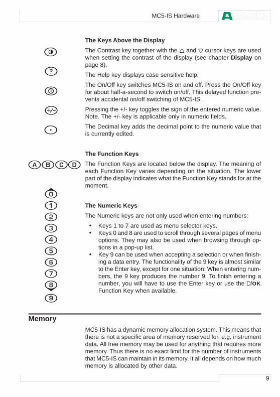
KeyboardThe keys on theMC5-IS’ keyboardare grouped accord-ing to their functionas follows:
The Cursor Keys and the Enter KeyThe Cursor keys and the Enter key are located close to the upperleft corner of the display.
The Cursor keys are used when moving the cursor on the screen.They also have several special functions in certain situations, e.g.when tuning the contrast of the display.
The Enter key finishes the entering of values.
9
The Keys Above the DisplayThe Contrast key together with the and cursor keys are usedwhen setting the contrast of the display (see chapter Display onpage 8).
The Help key displays case sensitive help.
The On/Off key switches MC5-IS on and off. Press the On/Off keyfor about half-a-second to switch on/off. This delayed function pre-vents accidental on/off switching of MC5-IS.
Pressing the +/- key toggles the sign of the entered numeric value.Note. The +/- key is applicable only in numeric fields.
The Decimal key adds the decimal point to the numeric value thatis currently edited.
The Function KeysThe Function Keys are located below the display. The meaning ofeach Function Key varies depending on the situation. The lowerpart of the display indicates what the Function Key stands for at themoment.
The Numeric KeysThe Numeric keys are not only used when entering numbers:
• Keys 1 to 7 are used as menu selector keys.• Keys 0 and 8 are used to scroll through several pages of menu
options. They may also be used when browsing through op-tions in a pop-up list.
• Key 9 can be used when accepting a selection or when finish-ing a data entry. The functionality of the 9 key is almost similarto the Enter key, except for one situation: When entering num-bers, the 9 key produces the number 9. To finish entering anumber, you will have to use the Enter key or use the D/OKFunction Key when available.
MemoryMC5-IS has a dynamic memory allocation system. This means thatthere is not a specific area of memory reserved for, e.g. instrumentdata. All free memory may be used for anything that requires morememory. Thus there is no exact limit for the number of instrumentsthat MC5-IS can maintain in its memory. It all depends on how muchmemory is allocated by other data.
MC5-IS Hardware
10
General
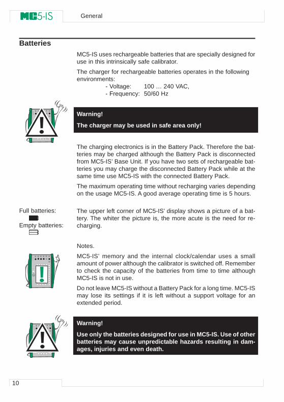
BatteriesMC5-IS uses rechargeable batteries that are specially designed foruse in this intrinsically safe calibrator.
The charger for rechargeable batteries operates in the followingenvironments:
- Voltage: 100 … 240 VAC,- Frequency: 50/60 Hz
Warning!
The charger may be used in safe area only!
The charging electronics is in the Battery Pack. Therefore the bat-teries may be charged although the Battery Pack is disconnectedfrom MC5-IS’ Base Unit. If you have two sets of rechargeable bat-teries you may charge the disconnected Battery Pack while at thesame time use MC5-IS with the connected Battery Pack.
The maximum operating time without recharging varies dependingon the usage MC5-IS. A good average operating time is 5 hours.
The upper left corner of MC5-IS’ display shows a picture of a bat-tery. The whiter the picture is, the more acute is the need for re-charging.
Notes.
MC5-IS’ memory and the internal clock/calendar uses a smallamount of power although the calibrator is switched off. Rememberto check the capacity of the batteries from time to time althoughMC5-IS is not in use.
Do not leave MC5-IS without a Battery Pack for a long time. MC5-ISmay lose its settings if it is left without a support voltage for anextended period.
Warning!
Use only the batteries designed for use in MC5-IS. Use of otherbatteries may cause unpredictable hazards resulting in dam-ages, injuries and even death.
Do not charge the batteries in hazardous area.
Full batteries:
Empty batteries:

11
About the Charger and the Charging ProcedureThe charger is connected to the charger connector at the bottom ofMC5-IS. The charging electronics informs you of the phases of thecharging procedure with the help of the charge status light.
� � � $ � � � � � � � � � �
� � � $ � � � � � � � � � $ �
When connecting the charger, the charging electronics first checksthe starting conditions. At this stage the charge status light is green.If the starting conditions are not met (e.g. the temperature is out-side the allowed range), the status light is blinking green.
When the charge status light is blinking red, a recharging is inprogress. MC5-IS may be used during the recharging phase. Emptybatteries are fully charged in approx. 5 hours.
When the charge status light is green, the batteries are charged. Atthis stage the charging electronics provide a support voltage thatprevents the batteries from discharging
Warnings!
USE ONLY THE CHARGER PROVIDED WITH THE CALIBRATOR(BC14-IS). USE THE CHARGER IN SAFE AREA ONLY!
The charger accepts input voltages from 100 to 240 VAC.
The charger should only be used indoors in a non-hazardousarea and the temperature should be in range 10 … 35 °C(50 … 95 °F).
MC5-IS Hardware
12
General
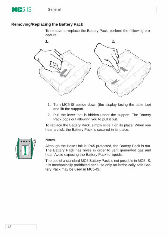
Removing/Replacing the Battery PackTo remove or replace the Battery Pack, perform the following pro-cedure:
1. 2.
1. Turn MC5-IS upside down (the display facing the table top)and lift the support.
2. Pull the lever that is hidden under the support. The BatteryPack pops out allowing you to pull it out.
To replace the Battery Pack, simply slide it on its place. When youhear a click, the Battery Pack is secured in its place.
Notes.
Although the Base Unit is IP65 protected, the Battery Pack is not.The Battery Pack has holes in order to vent generated gas andheat. Avoid exposing the Battery Pack to liquids.
The use of a standard MC5 Battery Pack is not possible in MC5-IS.It is mechanically prohibited because only an intrinsically safe Bat-tery Pack may be used in MC5-IS.
13
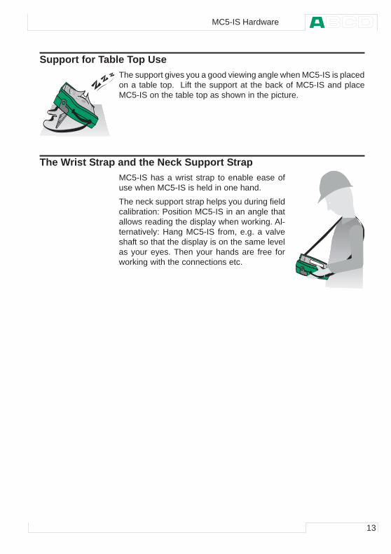
Support for Table Top UseThe support gives you a good viewing angle when MC5-IS is placedon a table top. Lift the support at the back of MC5-IS and placeMC5-IS on the table top as shown in the picture.
The Wrist Strap and the Neck Support StrapMC5-IS has a wrist strap to enable ease ofuse when MC5-IS is held in one hand.
The neck support strap helps you during fieldcalibration: Position MC5-IS in an angle thatallows reading the display when working. Al-ternatively: Hang MC5-IS from, e.g. a valveshaft so that the display is on the same levelas your eyes. Then your hands are free forworking with the connections etc.
MC5-IS Hardware
14
General
MC5-IS Firmware
MC5-IS’ firmware is saved in FLASH memory. Therefore it is rela-tively easy to update the firmware whenever a new version withfresh capabilities is released. See Firmware Update on page 29for more information on updating the firmware in your MC5-IS.
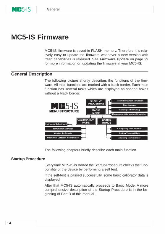
General DescriptionThe following picture shortly describes the functions of the firm-ware. All main functions are marked with a black border. Each mainfunction has several tasks which are displayed as shaded boxeswithout a black border.
The following chapters briefly describe each main function.
Startup ProcedureEvery time MC5-IS is started the Startup Procedure checks the func-tionality of the device by performing a self test.
If the self-test is passed successfully, some basic calibrator data isdisplayed.
After that MC5-IS automatically proceeds to Basic Mode. A morecomprehensive description of the Startup Procedure is in the be-ginning of Part B of this manual.
� � % � � ! � � & � � ' ! � �
� % � ( � � )( % ( � � �
% � * � � � � $ � � � � � � � � + � � � �
� � ( ! � � � � ! � � ! � � �� � � � � � � $ � � � � � � � � � � � $
� � � � � � � � � � , - � � � � � � � � , � � � � � � � � � �
� � � � $ � � � � $ � � � � � � � � + � � � � �
� � � � � � $ � � � � � � � � � � ' � � �
� � � � � � � � � � ' � � � + � � � � � � � � � � � � � �
� � � � � � � � � � % � * � � � � � �
. � � / � � $ � � � � � � � � �
� � � � � � � � � � � � � � + � � � � �
� � � � � � � � � � , � / � � � � � � � � � � � � �
' � � � � " $ $ � � $
� � % � � ! � � & � � ' ! � �
0 % � � � �� & ' �
� % � ( � � )( % ( � � �
� % " � 0 � % � � & (� & ' �
� � ( ! � � � � ! � � ! � � �
15
Basic ModeIn Basic Mode you can measure and generate/simulate signals.There are two separately configurable windows available. BasicMode is often used for testing connections before starting the ac-tual calibration procedure of an instrument.
Stepping and Ramping tools enable generating/simulating signalsthat vary with time.
All main functions of Basic Mode are described in part B of thismanual.
Part C concentrates on Basis Mode’s higher level functions andadditional information.
MaintenanceThis main function handles calibrator configuration settings.
Additionally there is the possibility to recalibrate MC5-IS (requires apassword).
Maintenance level subjects are handled in Part C of this Manual.
Calibration ModeMC5-IS’ main duty is calibrating instruments. Therefore very spe-cial attention was directed on this matter when creating the calibra-tor. MC5-IS may be used as a stand-alone calibrator i.e. all instru-ment data and calibration history data is saved in MC5-IS’ ownmemory. Optionally MC5-IS also communicates with calibrationsoftware.
MC5-IS supports the use of instruction texts. They help the techni-cian to perform the calibration as fluently as possible. You may en-ter three kinds of instruction texts: Starting Guide, Adjusting Guideand Finishing Guide. Additionally, calibration notes can be enteredafter the calibration procedure.
More calibration related information is available in Part D of thismanual.
Calibration ResultsThe graphical representation as well as numeric data of the calibra-tion results may be viewed in MC5-IS. Transferring the results toQCAL® calibration software makes it possible to view the results inPC environment.
More information concerning calibration results is presented in PartD of this manual.
MC5-IS Firmware
16
General
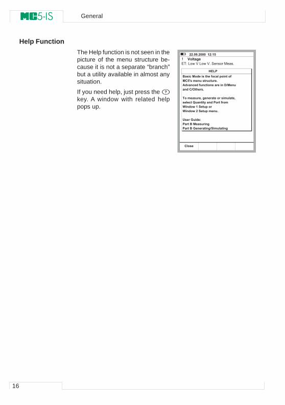
Help FunctionThe Help function is not seen in thepicture of the menu structure be-cause it is not a separate “branch”but a utility available in almost anysituation.
If you need help, just press the key. A window with related helppops up.
� � 1 2 3 1 � 2 2 2 � � 4 � 5 4 6 �
� � � � � . � � � $ �� � � � � � � � � � � � � � � � � � � � � � �
0 � � � � � � � � � � � � � � � � � � � � � � � � �� � 6 7 � � � � � � � � � � � � � � 1 �% � 8 � � � � � � � � � � � � � � � � � � � � � ' , � � � � �� � � � � , & � � � 1
� � � � � � � � 9 � $ � � � � � � � � � � � � � � � � � 9 � � � � � � � : � � � � � � ; � � � � � � � � � � � � �< � � � / � 4 � � � � � � � �< � � � / � � � � � � � � � � � � � 1
! � � � - � � � � 5 � � � � 0 � � � � � � � � $ � � � � 0 � - � � � � � � � � $ , � � � � � � � � � $
= � "
� � �
17
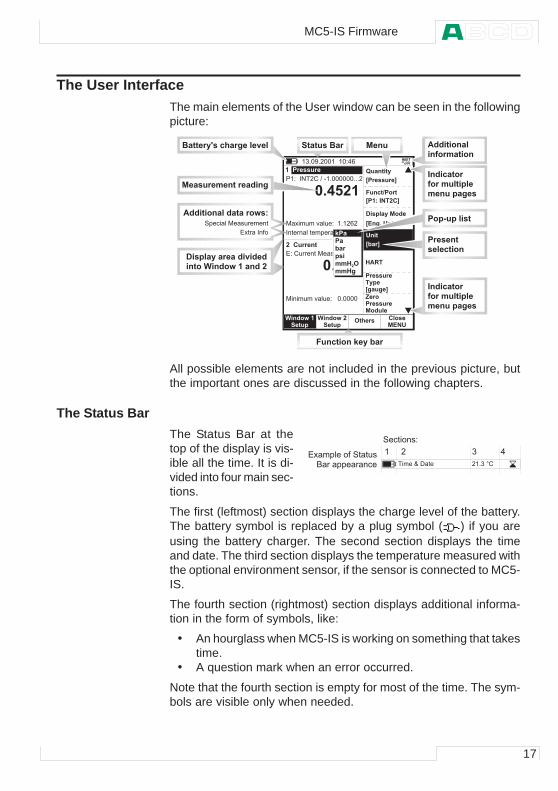
The User InterfaceThe main elements of the User window can be seen in the followingpicture:
All possible elements are not included in the previous picture, butthe important ones are discussed in the following chapters.
The Status BarThe Status Bar at thetop of the display is vis-ible all the time. It is di-vided into four main sec-tions.
The first (leftmost) section displays the charge level of the battery.The battery symbol is replaced by a plug symbol ( ) if you areusing the battery charger. The second section displays the timeand date. The third section displays the temperature measured withthe optional environment sensor, if the sensor is connected to MC5-IS.
The fourth section (rightmost) section displays additional informa-tion in the form of symbols, like:
• An hourglass when MC5-IS is working on something that takestime.
• A question mark when an error occurred.
Note that the fourth section is empty for most of the time. The sym-bols are visible only when needed.
� � �< � � � / � 4 < � � � / � �� � ( !� � �
& � � � � � � � � � � � � �
2 1 > 6 � 4 � + � �� $ � � $ � �
% � � � � � ?
� � � � � � � � � � � � � � � � � � � � � � � � � � � � � �
� � � � � � � � � ! � � � � � � � � " � � � � � � � � � �
2 1 4 4 �
� � � � � � � � � �
+ � �
� � � � �
� � � � � � � � # � � � � � � � � #
: � � � � � � ;
@ � � � � � A
@ 4 5 � � ( � � � A
@ � � $ 1 � ! � � � A
! � � �
@ + � � A
# � � � � , � �
' � � � � ; � � � �
B � �+ � �� �� � = � & �� � = $
� $ � � % � � � � � � � � � � & " �
4 �
= % � �
� ; � �@ $ � � $ � A
� � � � �� � � � �
� � � � �
C � �
� � # � � � ! � # � ' � �
� � � � � � � � � ! � � � � � � � � � � �
� � � � � � � � � � � � � � � � � $
' � � � � ; � � � � � � � � 8 � � � � �� � � � < � � � / � 4 � � � � � � �
� � � �
� ) � � � � � �
� � � � � � � � � � � � �
� � � � � � � � �� � � � � � � � � � � �� � � � � � � $ �
� � � � � � 0 � � �
# � � � � � � � B � ; � + � �
0 � � � � � ; 7 � � � � $ � � � � 8 � � % � � � � � � � � � �� � � � � � � � �
� � � � � � � � �� � � � � � � � � � � �� � � � � � � $ �
� ' ( � � ! � � � � � � � � #
� � # � � � � � ) �
% � � � � � � � � � � � � � � � / 5
� ( # � � � � �
� � &
� � � � * � + � # �
� � � � ' ! � � ) � � # � # � � �, � � � � ' ' � � � � (
$
� � � $ � - � �
MC5-IS Firmware
18
General
The Function Key BarThe Function Key Bar at the bottom of the display is visible all thetime. The meaning of the Function Keys varies depending on thesituation.
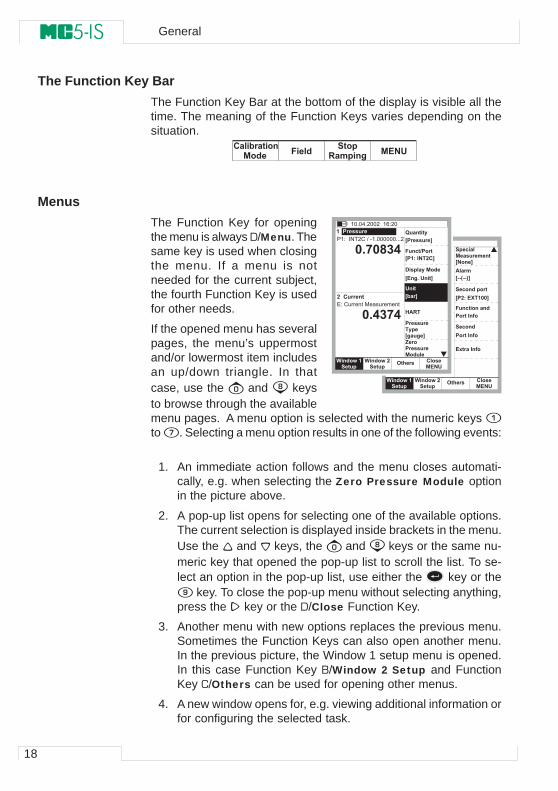
MenusThe Function Key for openingthe menu is always D/Menu. Thesame key is used when closingthe menu. If a menu is notneeded for the current subject,the fourth Function Key is usedfor other needs.
If the opened menu has severalpages, the menu’s uppermostand/or lowermost item includesan up/down triangle. In thatcase, use the and keysto browse through the availablemenu pages. A menu option is selected with the numeric keys to . Selecting a menu option results in one of the following events:
1. An immediate action follows and the menu closes automati-cally, e.g. when selecting the Zero Pressure Module optionin the picture above.
2. A pop-up list opens for selecting one of the available options.The current selection is displayed inside brackets in the menu.Use the and keys, the and keys or the same nu-meric key that opened the pop-up list to scroll the list. To se-lect an option in the pop-up list, use either the key or the
key. To close the pop-up menu without selecting anything,press the key or the D/Close Function Key.
3. Another menu with new options replaces the previous menu.Sometimes the Function Keys can also open another menu.In the previous picture, the Window 1 setup menu is opened.In this case Function Key B/Window 2 Setup and FunctionKey C/Others can be used for opening other menus.
4. A new window opens for, e.g. viewing additional information orfor configuring the selected task.
� + � �� $ � � $ � �
% � � � � � ?
2 1 6 + � �
� � � � � � �� � � � � � � � � �@ ( � � A
@ ) ) � ) ) � A
# � � � � � � � � � � �
� � � � � �
% � � � �
� � � � �
� � � � � � � � �
� � � � � �
� � �� � ( !� � �
& � � � < � � � / � 4 < � � � / � �� � � � � � � � � �
@ � 5 � � D � 4 2 2 A
� � � � � � � � �
� � �� � ( !� � �
& � � �
2 1 E 2 F � > � + � �� $ � � $ � �
% � � � � � ?
� � � � � � � � � � � � � � � � � � � � � � � � � � � � � �
2 1 6
2 1 > � E >
� � � � � � � � � �
+ � �
� � � � �
� � � � � � � � # � � � � � � � � #
: � � � � � � ;
@ � � � � � A
@ 4 5 � � ( � � � A
@ � � $ 1 � ! � � � A
! � � �
@ + � � A
# � � � � , � �
' � � � � ; � � � �
� � � � & � � � � � � � � " � � � �
4 �
= % � �
� � � � �� ; � �@ $ � � $ � AC � � � � � � � �� � � � �
< � � � / � 4 < � � � / � �� � � � � � � � � �
� � �� � � � + � � � � � � � �� � ( !� � �# � � � �� � � � � � � � � $
19
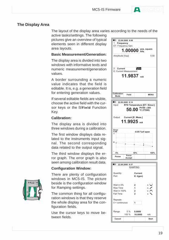
The Display AreaThe layout of the display area varies according to the needs of theactive tasks/settings. The followingpictures give an overview of typicalelements seen in different displayarea layouts.
Basic Measurement/Generation:The display area is divided into twowindows with informative texts andnumeric measurement/generationvalues.
A border surrounding a numericvalue indicates that the field iseditable. It is, e.g. a generation fieldfor entering generation values.
If several editable fields are visible,choose the active field with the cur-sor keys or the B/Field FunctionKey.
Calibration:The display area is divided intothree windows during a calibration.
The first window displays data re-lated to the instruments input sig-nal. The second correspondingdata related to the output signal.
The third window displays the er-ror graph. The error graph is alsoseen among calibration result data.
Configuration Window:There are plenty of configurationwindows in MC5-IS. The picturebeside is the configuration windowfor Ramping settings.
The common thing for all configu-ration windows is that they reservethe whole display area for the con-figuration fields.
Use the cursor keys to move be-tween fields.
� � 1 2 3 1 � 2 2 2 � � F 5 2 G
� � � � � # � � H � � � � ;
� � � � � � � � � � � �
� � � � . � / � � ( 0 � 1 � �
� � � � � � � � # � � � � � � � � #
2 � ' ! � # � 3 � 4 ' ' 5
� 1 � H � � � �B = I
6 � � �
4 1 2 2 2 2 2
4 4 1 3 F � E
� � �� � � � + � � � � � � � ( !
� %
# � � � �
� � 1 2 3 1 � 2 2 2 � � F 5 4 > �
� � ' � #
� � � �2 1 > 2
7 � # ' � #
� 4 2 2 � � � F 6J � � � � � � 3 2 �
4 4 1 3 3 � 6
) 2 1 2 6 � K � � � � �
6 2 1 2 2
� � �% � � � � �# � � �
L
2
)2 K 6 2 K 4 2 2 K
� � ' � � � � � � � � � � � � � @ � � 5 � � � � � � 1 A
� � � � � � � � @ � 5 � � � � 1 A
� %
� � 1 2 3 1 � 2 2 2 � � F 5 � E �
8 2 � � � � 1
� � � � � � � � � � �
9 � � � # � # 0
� � � #
: � � # � � � � � ;
8 � � � � � �
: � � # � � � � � � � ;
. � ! ! � � � �
8 ' � # �
� � < � ( � � # � � � � � �
8 � � = � � ;
� � � � ;
� � � � � � �� 5 � � � $ � � �
�4��
4
F 1 2 2 2 24 G 1 2 2 2 2
�
�
�
�
� 2
MC5-IS Firmware
20
General
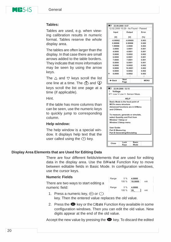
Tables:Tables are used, e.g. when view-ing calibration results in numericformat. Tables reserve the wholedisplay area.
The tables are often larger than thedisplay. In that case there are smallarrows added to the table borders.They indicate that more informationmay be seen by using the arrowkeys.
The and keys scroll the listone line at a time. The and keys scroll the list one page at atime (if applicable).
Hint.
If the table has more columns thancan be seen, use the numeric keysto quickly jump to correspondingcolumn.
Help window:The help window is a special win-dow. It displays help text that theuser called using the key.
Display Area Elements that are Used for Editing DataThere are four different fields/elements that are used for editingdata in the display area. Use the B/Field Function Key to movebetween editable fields in Basic Mode. In configuration windows,use the cursor keys.
Numeric FieldsThere are two ways to start editing anumeric field:
1. Press a numeric key, or key. Then the entered value replaces the old value.
2. Press the key or the C/Edit Function Key available in someconfiguration windows. Then you can edit the old value. Newdigits appear at the end of the old value.
Accept the new value by pressing the key. To discard the edited
� � 1 2 3 1 � 2 2 2 � � F 5 > E �
� � � � 0 � � B � $ �( � � � � � ( !
� � � � � � � � � � � � � � � % � � � 2 � � . � � � 3 � � � � � � � 3
� � � � �
@ . A
) 2 1 2 2 2 2 �
2 1 3 3 3 3 G
4 1 3 3 3 3 F
� 1 2 2 2 2
> 1 2 2 2 2
6 1 2 2 2 2
G 1 2 2 2 2
E 1 2 2 2 2
F 1 2 2 2 2
3 1 2 2 2 2
3 1 3 3 3 3
3 1 2 2 2 2
F 1 2 2 2 2
& � � � � �
@ . A
) 2 1 2 2 2 2 6
2 1 3 3 3 3 G
� 1 2 2 2 2
� 1 2 2 2 4
> 1 2 2 2 4
6 1 2 2 2 �
G 1 2 2 2 4
E 1 2 2 2 4
F 1 2 2 2 4
3 1 2 2 2 �
4 2 1 2 2 2 4
3 1 2 2 2 �
F 1 2 2 2 �
� � � �
@ K A
2 1 2 2 �
2 1 2 2 2
2 1 2 2 �
2 1 2 2 4
2 1 2 2 4
2 1 2 2 �
2 1 2 2 4
2 1 2 2 4
2 1 2 2 4
2 1 2 2 �
2 1 2 2 �
2 1 2 2 �
2 1 2 2 �� �
� � 1 2 3 1 � 2 2 2 � � 4 � 5 4 6 �
� � � � � . � � � $ �� � � � � � � � � � � � � � � � � � � � � � �
0 � � � � � � � � � � � � � � � � � � � � � � � � �� � 6 7 � � � � � � � � � � � � � � 1 �% � 8 � � � � � � � � � � � � � � � � � � � � � ' , � � � � �� � � � � , & � � � 1
� � � � � � � � 9 � $ � � � � � � � � � � � � � � � � � 9 � � � � � � � : � � � � � � ; � � � � � � � � � � � � �< � � � / � 4 � � � � � � � �< � � � / � � � � � � � � � � � � � 1
! � � � - � � � � 5 � � � � 0 � � � � � � � � $ � � � � 0 � - � � � � � � � � $ , � � � � � � � � � $
= � "
� � �M � ; " � B
� � �0 � � �
8 � � = � � ;
� � � � ;
> 1 2 2 2 24 G 1 2 2 2 2 � 2
8 � � = � � ;
� � � � ;
> 1 2 2 2 2� 2 N � 2
21
value, use the A/Cancel Function Key. See also Part B for specialfeatures concerning numeric fields when generating a signal.
Notes.
You cannot add more digits if the length of the number is at itsmaximum limit. Use the C/ Delete Function Key to remove un-wanted digits first and then enter the new digits.
The dual function of the keys: , and is not available in anumeric field. The keys only represent numbers.
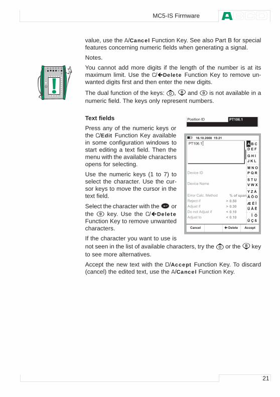
Text fieldsPress any of the numeric keys orthe C/Edit Function Key availablein some configuration windows tostart editing a text field. Then themenu with the available charactersopens for selecting.
Use the numeric keys (1 to 7) toselect the character. Use the cur-sor keys to move the cursor in thetext field.
Select the character with the orthe key. Use the C/ DeleteFunction Key to remove unwantedcharacters.
If the character you want to use isnot seen in the list of available characters, try the or the keyto see more alternatives.
Accept the new text with the D/Accept Function Key. To discard(cancel) the edited text, use the A/Cancel Function Key.
� � � � # � � � � � + � 4 2 G 1 4
4 G 1 4 2 1 � 2 2 2 � � 4 6 5 � 4 �
K � � � � � �
2 1 6 2
2 1 � 2
2 1 4 2
2 1 4 2
� � � � � � � � � ' � � � � � % � � � � �
' � � � # �
- � = � � �
� � M � " �
� � ( � & �
� : � � �
� � � � ! �
. � < � D �
O � C � P �
Q � R � & �
S � T � U �
V � W � X �
� � � � Y � � Z �
[ � \ � ] �
% � 0 � � �
+ � ( � � +
+ � ( � � � �
� � � � � � � � ! ( � � � # > � 3
8 ? ( # � � )
2 3 ? � � # � � )
+ � � � � # � 2 3 ? � � # � � )
2 3 ? � � # � # �
?
?
^
^
� � � � " � �
MC5-IS Firmware
22
General
Drop Down Lists
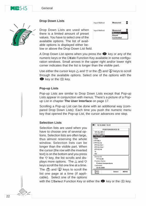
Drop Down Lists are used whenthere is a limited amount of presetvalues. You have to select one of theavailable options. The list of avail-able options is displayed either be-low or above the Drop Down List field.
A Drop Down List opens when you press the key or any of thenumeric keys or the C/Edit Function Key available in some configu-ration windows. Small arrows in the upper right and/or lower rightcorner indicates that the list is longer than the visible part.
Use either the cursor keys and or the and keys to scrollthrough the available options. Select one of the options with the
key or the key.
Pop-up ListsPop-up Lists are similar to Drop Down Lists except that Pop-upLists appear in conjunction with menus. There’s a picture of a Pop-up List in chapter The User Interface on page 17.
Scrolling a Pop-up List can be done with an additional way (com-pared Drop Down Lists): Each time you push the numeric menukey that opened the Pop-up List, the cursor advances one step.
Selection ListsSelection lists are used when youhave to choose one of several op-tions. Selection lists are often large,thus almost reserving the wholewindow. Selection lists can belonger than the visible part. Whenthe cursor (the row with the invertedtext) is on the bottom and you pressthe key, the list scrolls and dis-plays more options. The and keys scroll the list one line at a time.The and keys to scroll thelist one page at a time (if appli-cable). Select one of the optionswith the C/Select Function Key or either the key or the key.
� � � � � � �� � ' � # � � # > � 3
� � � � � � �
M � ; � �� � � � � � � �
� � � � � � �� � ' � # � � # > � 3
4 G 1 4 2 1 � 2 2 2 � � 4 6 5 � 4 �
& � � � � & ( , ' � . � � � � � '
4 2 4 ) D " ) 2 2 4 1 44 4 � ) � � ) 2 2 � 1 4
� � / � 4 2 G 1 4 � 4 4 � 1 4 � � 4 4 � 1 4 6 ) 4 � 4 4 � 1 4 6 ) � � 4 4 � 1 4 G� �
4 4 � ) � � ) 2 2 E 1 4
0 � � �� � �
� � ( !
. .
+ � ( � � +
� � 4 4 � 1 2 3� � � � # � � � � � � �
� � � � � � � � � � � � � � � � �� � ! � � � � # 3
� � 1 2 � 1 � 2 2 2
� � � � � �
23
MC5-IS’ Modularity and Options
MC5-IS includes several optional modules both in hardware andfirmware. This makes it possible to buy a calibrator with capabilitiesaccording to current requirements. If additional needs arise lateron, add more modules to your MC5-IS and you will have a tool thatsuits all demands.
Hardware Modules/Options
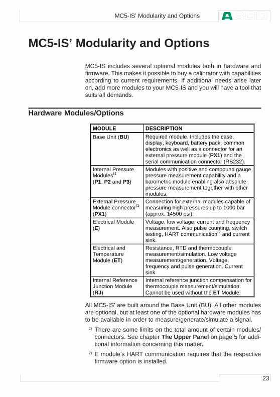
All MC5-IS’ are built around the Base Unit (BU). All other modulesare optional, but at least one of the optional hardware modules hasto be available in order to measure/generate/simulate a signal.
1) There are some limits on the total amount of certain modules/connectors. See chapter The Upper Panel on page 5 for addi-tional information concerning this matter.
2) E module’s HART communication requires that the respectivefirmware option is installed.
MODULE DESCRIPTIONBase Unit (BU) Required module. Includes the case,
display, keyboard, battery pack, commonelectronics as well as a connector for anexternal pressure module (PX1) and theserial communication connector (RS232).
Internal PressureModules(1
(P1, P2 and P3)
Modules with positive and compound gaugepressure measurement capability and abarometric module enabling also absolutepressure measurement together with othermodules.
External PressureModule connector(1
(PX1)
Connection for external modules capable ofmeasuring high pressures up to 1000 bar(approx. 14500 psi).
Electrical Module(E)
Voltage, low voltage, current and frequencymeasurement. Also pulse counting, switchtesting, HART communication(2 and currentsink.
Electrical andTemperatureModule (ET)
Resistance, RTD and thermocouplemeasurement/simulation. Low voltagemeasurement/generation. Voltage,frequency and pulse generation. Currentsink
Internal ReferenceJunction Module(RJ)
Internal reference junction compensation forthermocouple measurement/simulation.Cannot be used without the ET Module.
MC5-IS’ Modularity and Options
24
General
Other Connectable DevicesMC5-IS’ connector for External Pressure Modules (EXT) allows theuse of additional pressure modules. This possibility increases themeasurable pressure range from the range available using only theinternal modules.
Firmware OptionsThe standard firmware shipped with MC5-IS is capable of perform-ing all normal measurement, generation/simulation and calibrationtasks. The optional tools give you additional features that enhanceMC5-IS’ functionality.
The following firmware options are already available (valid whenthis manual was printed):
• Special temperature sensors• Communication with QCAL® software• HART communication (Requires the E module)• Multichannel datalogging
25
Safety
MC5-IS’ case is water/dust proof (IP65). The battery pack doeshowever have holes to enable proper ventilation and heat transfer.So be careful when working in wet conditions.
Opening of the casing of MC5-IS is not allowed due to ATEX safetyreasons.
The materials of MC5-IS’ case withstand normal industrial condi-tions. MC5-IS endures shocks with the help of the built in impactprotectors
Internal pressure modules with a measuring range of 6 bar (90 psi)or less are overpressure protected. If the measurement pressure ofa pressure module exceeds the module’s maximum pressure value,the overpressure protector vents excess pressure through a hole inthe rear of the case.
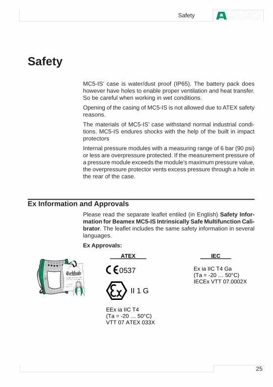
Ex Information and ApprovalsPlease read the separate leaflet entiled (in English) Safety Infor-mation for Beamex MC5-IS Intrinsically Safe Multifunction Cali-brator. The leaflet includes the same safety information in severallanguages.
Ex Approvals:
Safety
ATEX IEC
0537
II 1 G
EEx ia IIC T4 (Ta = -20 … 50°C) VTT 07 ATEX 033X
Ex ia IIC T4 Ga (Ta = -20 … 50°C) IECEx VTT 07.0002X
26
General
Safety Precautions and WarningsMC5-IS calibrator is a precision calibration tool that should be used by skilledpeople. Working with MC5-IS involves the usage of pressure, temperatureand/or electrical instruments. Be sure to know how to work with these in-struments and how to safely connect/disconnect pressure hoses as well aselectrical test leads clips, etc.
Use MC5-IS only if you are certain of that it can be used safely. Safe use ofMC5-IS is no longer possible if one or more of the following cases are true:
• When the case of MC5-IS is evidently damaged• When MC5-IS is not functioning as expected• After prolonged storage in unfavorable conditions• After serious damage during transport
Sometimes it is necessary to use a portable radio transceiver while workingwith the calibrator. To prevent calibration errors caused by the radio fre-quency interference, keep the radio far (at least 1 meter) from the calibratorand the circuit under calibration while sending.
General WarningsUse only cables provided by Beamex when connecting MC5-ISto a PC. Replace faulty cables with new ones from Beamex.MC5-IS uses a rechargeable Battery Pack. They are consideredas hazardous waste. Dispose used batteries properly accord-ing to local regulations.Avoid short circuiting the batteries. The short circuit currentmay cause burns to you, damage to the device or even fire.Notice, that also new replacement batteries are shipped incharged state.Rechargeable batteries may vent small amounts of gas duringrecharge. The vented gas mixture may be highly explosive, butnormally it diffuses rapidly into the atmosphere. To avoid dan-ger, use only the original charger and never recharge in a gas-tight container.The charger should be used indoors and in a safe area only.The ambient temperature should not exceed 35 °C (95 °F) dur-ing use.To avoid interference: When connecting instruments to MC5-IS, use shielded cables if the cable length is more than threemeters (approx 10 feet).
Warnings Concerning the use of Electrical Modules (E and ET)The measurement and generation terminals of MC5-IS are pro-tected against over voltage and over current as far as it has
27
been possible without affecting the accuracy. The circuits aredesigned so, that you can connect a voltage source 30VDC/215mA or max. 1 W between any terminals without damagingthe device. However, long exposure to this kind of stress mayaffect the accuracy.
Although there is a galvanic isolation between MC5-IS’ ET andE modules, it is for functional purposes only. The max. 30 Vrestriction applies between these modules too.
Maximum output voltage from MC5-IS’ terminals is below 16 V.If you, however, connect together voltages from the ET and Esections or if you connect external voltages to MC5-IS, the re-sulting voltage may be high enough to be hazardous.
General Warnings Concerning Pressure MeasurementThe accessory polyurethane hose supplied with an MC5-IS withpressure modules is rated to the maximum pressure of 20 barat 21°C (290 psi at 70°F). Applying higher pressure can be haz-ardous.
To avoid damaging the calibrator, use hand tightening onlywhen connecting the pressure measurement hoses (max.torque 5 Nm). If the use of tools is required to secure the connec-tion (typically pressure modules with a pressure range of 20bar or more), apply the counterforce with a spanner on the con-nector body’s hexagonal part.
Always depressurize the system before opening or connectingany pressure fittings or connectors. Use proper valves for vent-ing the system. Ensure that all connections are made correctlyand that the hose and the connectors are intact.
Always use the pressure media stated in the module’s sticker.Using unsuitable pressure media may destroy the pressuremodule. The internal module’s sticker is located at the rear ofMC5-IS. External modules have the sticker on the module it-self.
Never exceed the maximum pressure of a pressure module, beit internal or external. The pressure module’s maximum pres-sure is stated on the module’s sticker. The maximum pressureof external modules is also mentioned in the Instruction Leaf-let that is provided with the external module.
Never plug a hose with your hands or put the hands in front ofa gas spray coming from a leakage. A gas bubble in the bloodcirculation can cause death.
Safety
28
General
Warnings Concerning High PressureHigh pressure is always dangerous. Only personnel with goodexperience and knowledge of high pressure liquid, air and ni-trogen operations are allowed to work with the module. Readcarefully all these instructions and local safety instructions forhigh pressure operations before starting the use.
When using gas, the system must not contain any liquid, espe-cially if you do not know how they may react under pressure.Use of clean air or nitrogen is recommended as gaseous pres-sure media. Liquid pressure media should be preferred whenusing modules with a pressure range of 60 bar (30000 psi) ormore.
If you use nitrogen, minimize the leak to the atmosphere andtake care of sufficient ventilation. Close the valve of the nitro-gen cylinder, when the system is not in use. Increase in thepercentage of nitrogen in the ambient air may cause uncon-sciousness and death without warning. Read carefully thesafety instructions for nitrogen and make sure that the otherpeople in the same space are aware of the danger.
Use of liquid pressure medium is recommended with pressuremeasurement modules at higher pressure range. Use water orsuitable hydraulic oil. Check that the used liquid is not aggres-sive against the materials used in the transducer or tubing.When using liquid, minimize the amount of air in the system.So you can minimize the amount of spilled liquid in case ofleakage.
Do not use the same tubing with different liquids or gases.
Check what the local regulations say about construction anduse of pressurized vessels. The regulations normally controlconstruction and use of systems where the product of the pres-sure and volume exceeds a certain limit. The volume of thissystem depends on the instrument connected to it.
High pressure gas is dangerous because it can break the con-tainer and the flying splinters may cause injury. Also small leaksof gas may be dangerous because the high velocity of the leak-ing gas jet enables penetration through skin. If a gas bubblegets into the blood circulation, it can cause death. The leak jetis particularly penetrative, if some liquid is coming with thegas.
29
Service
MC5-IS may only be serviced by Beamex or a Beamex autho-rized service. Contact:
BEAMEX OY ABRistisuonraitti 10FIN-68600 PietarsaariFINLANDE-mail: [email protected]
Opening of the casing of MC5-IS is not allowed due to ATEX safetyreasons.
There are, however a few things that anyone using MC5-IS may do.
Firmware UpdateThe quickest way to see if a new firmware version is available ischecking out Beamex’s web site (http://www.beamex.com). Go tothe web page dedicated to MC5-IS and see what it says about firm-ware versions and downloads.
All you need is a Personal Computer and the Computer communi-cation cable that connects MC5-IS to one of the serial ports in yourPC.
Remember to backup all the instrument data in MC5-IS, using e.g.a calibration management software. Also check for possible releasenotes accompanying the updated file.
Recalibrating MC5-ISOnly laboratories approved by Beamex may recalibrate MC5-IS.Contact Beamex or your local representative for information con-cerning the recalibration of MC5-IS. Contact information is on thefirst pages of this User Guide.
The Battery ChargerThe charger is not intended to be serviced. When unusable it canbe thrown away according to local waste disposal regulations.
Service
30
General
Cleaning MC5-ISIf MC5-IS needs cleaning, use cloth soaked with a mild solution oftall oil soap (pine soap). Wait a few minutes and then rinse using acloth moistened with pure water. Never use any strong detergents.
Cleaning the Contacts of the Internal Reference Junction ModuleThe contacts of the Internal Reference Junction Block may needcleaning from time to time. The time period varies depending onthe environment MC5-IS is used in.
Carefully open the cover of the Internal Reference Junction Blockby using a screwdriver as a wrench. Now you can see the contacts.Remove all impurities and press back the cover. The cover is se-cured when you hear a click.

Startup andBasic Operation
Things discussed in Part B:
••••• What happens during thestartup procedure.
••••• Measuring signals and doingsome special measurements.
••••• Generating/simulating signals.••••• Step and Ramp functions.••••• Alarm limits.
32
Startup and Basic Operation
Starting MC5-IS
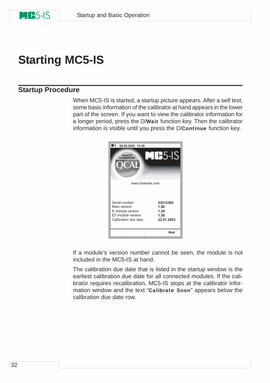
Startup ProcedureWhen MC5-IS is started, a startup picture appears. After a self test,some basic information of the calibrator at hand appears in the lowerpart of the screen. If you want to view the calibrator information fora longer period, press the D/Wait function key. Then the calibratorinformation is visible until you press the D/Continue function key.
If a module’s version number cannot be seen, the module is notincluded in the MC5-IS at hand.
The calibration due date that is listed in the startup window is theearliest calibration due date for all connected modules. If the cali-brator requires recalibration, MC5-IS stops at the calibrator infor-mation window and the text “Calibrate Soon” appears below thecalibration due date row.
� � � � � � � � � � � � � � � �
� � �
� � � � � � � � � � �
� � � � � � � � � � � � �
� � � � � � � � � � � � � � � � � �
� � � � � � � � � �
� � � � � � � � � � � � � �
� � � � � �
� � �
� � � � � � � � �
� � � �
� � � �
� � � � � � � � � � � � � �
33
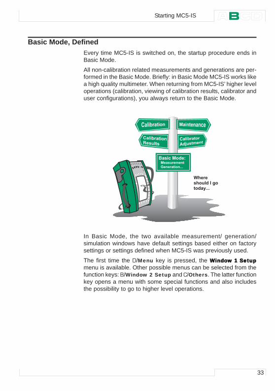
Basic Mode, DefinedEvery time MC5-IS is switched on, the startup procedure ends inBasic Mode.
All non-calibration related measurements and generations are per-formed in the Basic Mode. Briefly: in Basic Mode MC5-IS works likea high quality multimeter. When returning from MC5-IS’ higher leveloperations (calibration, viewing of calibration results, calibrator anduser configurations), you always return to the Basic Mode.
� � � � � �� � � � � � � � � � � � �� � � � � � � �
� � � � � � � � � � � � � � � � � � � � � �� � � � � � � � � � � � �
In Basic Mode, the two available measurement/ generation/simulation windows have default settings based either on factorysettings or settings defined when MC5-IS was previously used.
The first time the D/Menu key is pressed, the WWWWWindoindoindoindoindow 1 Setupw 1 Setupw 1 Setupw 1 Setupw 1 Setupmenu is available. Other possible menus can be selected from thefunction keys: B/Window 2 Setup and C/Others. The latter functionkey opens a menu with some special functions and also includesthe possibility to go to higher level operations.
Starting MC5-IS
34
Startup and Basic Operation
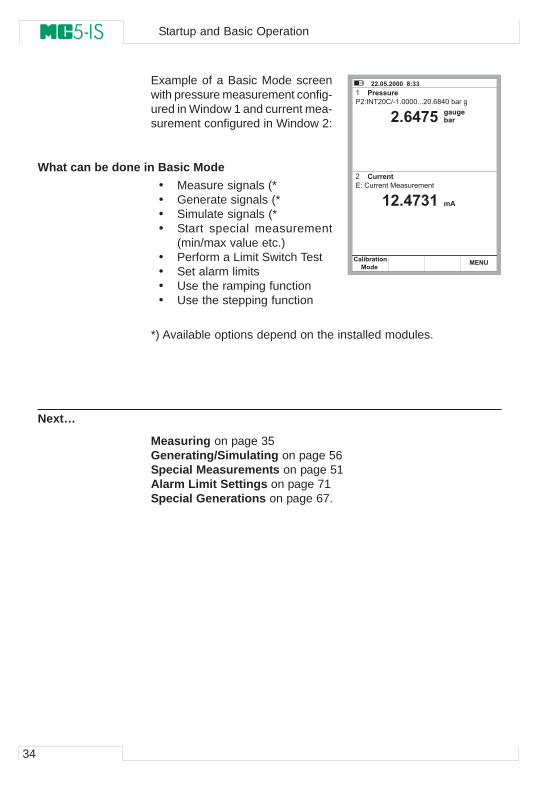
Example of a Basic Mode screenwith pressure measurement config-ured in Window 1 and current mea-surement configured in Window 2:
What can be done in Basic Mode• Measure signals (*• Generate signals (*• Simulate signals (*• Start special measurement
(min/max value etc.)• Perform a Limit Switch Test• Set alarm limits• Use the ramping function• Use the stepping function
*) Available options depend on the installed modules.
Next…
Measuring on page 35Generating/Simulating on page 56Special Measurements on page 51Alarm Limit Settings on page 71Special Generations on page 67.
� � � � � � � � � � � � � �
� � � � � ! � � � � � � �
� � � � � " � � � � � �
� � � � � � � � ! " � � � � � � � # $ % � � � � � &
� � � � � � � � � � � � � � � � �
� � � � �# � �� � � $ % �
� � � $ % �
� � � �" � � # � � � � � � � & ' (
� )
35
Measuring
All measurements in Basic Mode require that you first select theWindow to be used (Commands: Start with D/Menu and continueeither with A/Window 1 Setup or B/Window 2 Setup). Each mea-surement has its own unique 1/Quantity and 2/Function/Port set-tings in their window’s menu. The other window menu settings, e.g.measuring unit, refine the measurement characteristics.
When presenting measurements in this manual, the first paragraphtells the module (or modules) that is/are required for the measure-ment. Because of MC5-IS’ modularity you may or may not have therequired module. If the module is not included in your MC5-IS, the1/QuantityQuantityQuantityQuantityQuantity and 2/Function/PFunction/PFunction/PFunction/PFunction/Porororororttttt settings needed for the measure-ment are not available as choices in the pop-up lists.
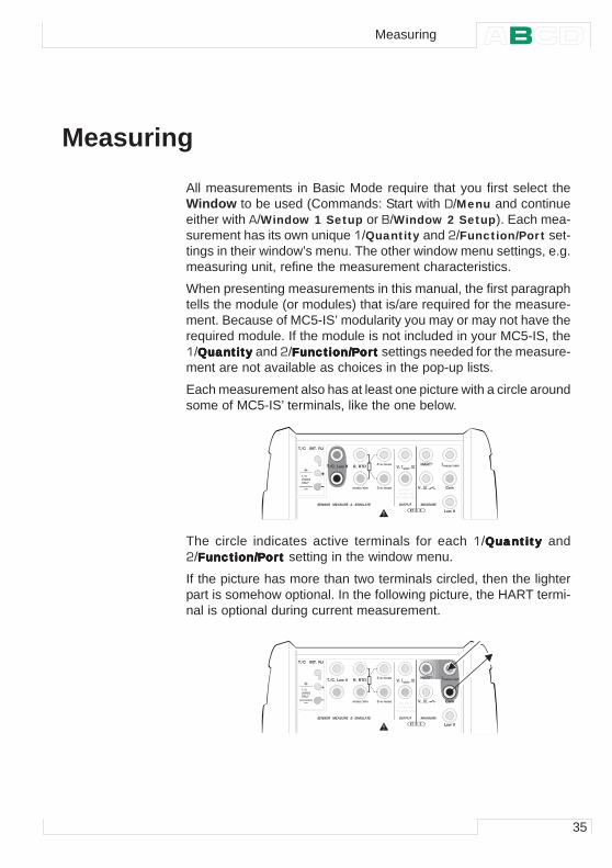
Each measurement also has at least one picture with a circle aroundsome of MC5-IS’ terminals, like the one below.
The circle indicates active terminals for each 1/QuantityQuantityQuantityQuantityQuantity and2/Function/PFunction/PFunction/PFunction/PFunction/Porororororttttt setting in the window menu.
If the picture has more than two terminals circled, then the lighterpart is somehow optional. In the following picture, the HART termi-nal is optional during current measurement.
� � � � � � � � �� � � � � � � � � � � � � �
� � � � � � � �
� � � � � � � � � � �� � � �
� � �
� � � �
� � �
� � � � � � �� � �
� � �
� � � � � � � � � � � �
� � � � � � � � � � � � � � � � � � � � � � � � � �
� � � � � � � �
� � � � � ! � � �
� " � � � � ! # � � $
� � � �
$ � � % �
& � � '
! � � � � � �
( � � � � � �� � � � � � � �
� � � � � � � � �
� � � � � � � � �� � � � � � � � � � � � � �
� � � � � � � �
� � � � � � � � � � �� � � �
� � �
� � � �
� � �
� � � � � � �� � �
� � �
� � � � � � � � � � � �
� � � � � � � � � � � � � � � � � � � � � � � � � �
� � � � � � � �
� � � � � ! � � �
� " � � � � ! # � � $
� � � �
$ � � % �
& � � '
! � � � � � �
( � � � � � �� � � � � � � �
� � � � � � � � � �
� � �
� � � �
Measuring

36
Startup and Basic Operation
Warning!
Do not apply voltage higher than 30 V/215 mA (max. 1 W) be-tween any terminals.
37
Pressure MeasurementSee chapter Things to Consider when Measuring Pressure on page 89 for more infor-mation on pressure measurement and internal/external pressure modules.
Required settings Options/description
Quantity PressurePressure Type g gauge pressure or
abs absolute pressure.
The available pressure types may be restricted because of the selected pressure port / pressure module. For more information concerning pressure types, see chapter Pres-sure Type on page 89 .
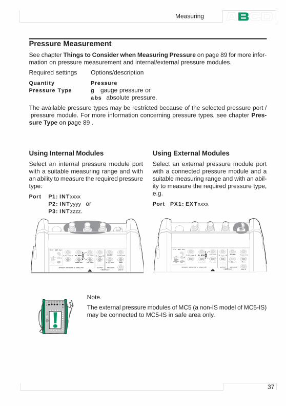
Using Internal ModulesSelect an internal pressure module portwith a suitable measuring range and withan ability to measure the required pressuretype:
Port P1: INTxxxxP2: INTyyyy orP3: INTzzzz.
Using External ModulesSelect an external pressure module portwith a connected pressure module and asuitable measuring range and with an abil-ity to measure the required pressure type,e.g.
Port PX1: EXTxxxx
� � � � � � � � �� � � � � � � � � � � � � �
� � � � � � � �
� � � � � � � � � � �� � � �
� � �
� � � �
� � �
� � � � � � �� � �
� � �
� � � � � � � � � � � �
� � � � � � � � � � � � � � � � � � � � � � � � � �
� � � � � � � �
� � � � � ! � � �
� " � � � � ! # � � $
� � � �
$ � � % �
& � � '
� � � �! � � � � � �
( � � � � � �� � � � � � � �
Note.
The external pressure modules of MC5 (a non-IS model of MC5-IS)may be connected to MC5-IS in safe area only.
Measuring
38
Startup and Basic Operation
Connecting and Removing External Pressure ModulesAn external pressure module may be connected and removed atany time. If a removed module was part of an active measurement,MC5-IS automatically changes the measurement to a suitable in-ternal pressure module. MC5-IS also emits a “beep” to inform youof the fact that the external pressure module used for pressuremeasurement was disconnected.
Zeroing a Pressure ModuleIf the selected pressure module does not display zero gauge pres-sure when the applied pressure is zero, the module has to be ze-roed.
Open the appropriate window setup menu (D/Menu, A/Window 1Setup or B/Window 2 Setup) and select menu option 7/Zero Pres-sure Module. If a secondary pressure module is active in the se-lected window, a pop-up menu will appear for choosing either tozero the primary or the secondary pressure module.
NOTE!
Zeroing a pressure module is especially important when theoperating position of MC5-IS is changed or the location of MC5-IS is changed in the vertical direction. Both of the above men-tioned factors affect notably on the pressure measurementmodules. Measuring pressure below 100 mbar (approx. 40 iwc)should be done with a firmly mounted MC5-IS (e.g. placed on atable top).
Next…
Special Measurements on page 51Alarm Limit Settings on page 71Special Generations on page 67Calibration, see Part D.
39
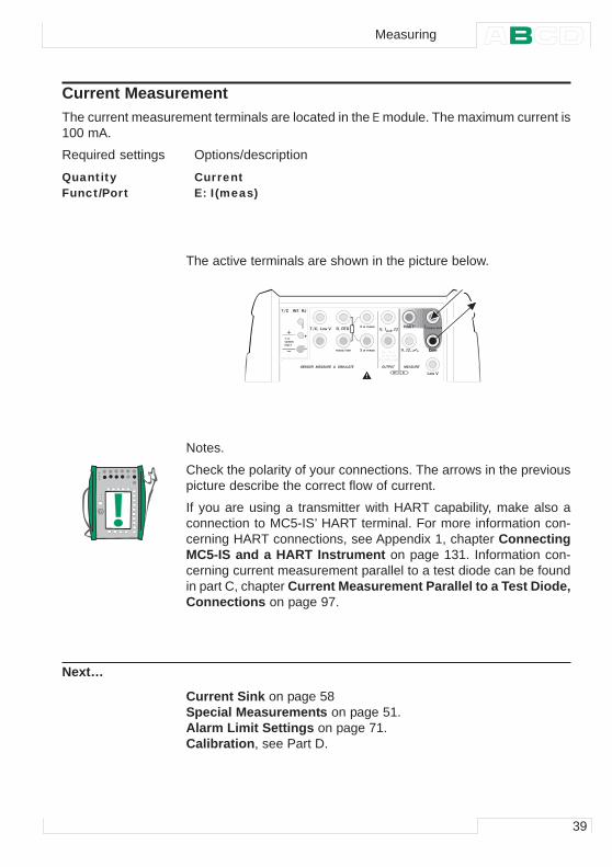
Current MeasurementThe current measurement terminals are located in the E module. The maximum current is100 mA.
Required settings Options/description
Quantity CurrentFunct/Port E: I(meas)
The active terminals are shown in the picture below.
Notes.
Check the polarity of your connections. The arrows in the previouspicture describe the correct flow of current.
If you are using a transmitter with HART capability, make also aconnection to MC5-IS’ HART terminal. For more information con-cerning HART connections, see Appendix 1, chapter ConnectingMC5-IS and a HART Instrument on page 131. Information con-cerning current measurement parallel to a test diode can be foundin part C, chapter Current Measurement Parallel to a Test Diode,Connections on page 97.
Next…
Current Sink on page 58Special Measurements on page 51.Alarm Limit Settings on page 71.Calibration, see Part D.
� � � � � � � � �� � � � � � � � � � � � � �
� � � � � � � �
� � � � � � � � � � �� � � �
� � �
� � � �
� � �
� � � � � � �� � �
� � �
� � � � � � � � � � � �
� � � � � � � � � � � � � � � � � � � � � � � � � �
� � � � � � � �
� � � � � ! � � �
� " � � � � ! # � � $
� � � �
$ � � % �
& � � '
! � � � � � �
( � � � � � �� � � � � � � �
� � � � � � � � � �
� � �
� � � �
Measuring
40
Startup and Basic Operation
Voltage MeasurementThe E module has terminals for low voltage measurement within the range ±250 mV andterminals for voltage measurement within ±30 V range. The ET module also has low volt-age measurement terminals with a range of ±250 mV. The ET module terminals are alsoused when measuring/simulating thermocouples using an external Reference Junction.
Required settings Options/description
Quantity VoltageFunct/Port ET: LowV(mea), E: LowV(mea) or E: V(meas)
MC5-IS displays the measured low voltage in the selected window.
Hint!
Low voltage measurement can be used for non-standard thermo-couple measurement. You will see the measured temperature inmillivolts and need a table to convert the measured millivolt value tocorresponding temperature values. In this case, use copper exten-sion cords to connect the non-standard thermocouple to MC5-IS’terminals.
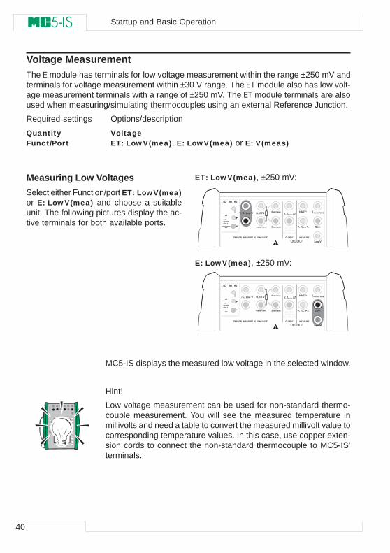
Measuring Low VoltagesSelect either Function/port ET: LowV(mea)or E: LowV(mea) and choose a suitableunit. The following pictures display the ac-tive terminals for both available ports.
ET: LowV(mea), ±250 mV:
E: LowV(mea), ±250 mV:
� � � � � � � � �� � � � � � � � � � � � � �
� � � � � � � �
� � � � � � � � � � �� � � �
� � �
� � � �
� � �
� � � � � � �� � �
� � �
� � � � � � � � � � � �
� � � � � � � � � � � � � � � � � � � � � � � � � �
� � � � � � � �
� � � � � ! � � �
� " � � � � ! # � � $
� � � �
$ � � % �
& � � '
! � � � � � �
( � � � � � �� � � � � � � �
� � � � � � � � �
� � � � � � � � �� � � � � � � � � � � � � �
� � � � � � � �
� � � � � � � � � � �� � � �
� � �
� � � �
� � �
� � � � � � �� � �
� � �
� � � � � � � � � � � �
� � � � � � � � � � � � � � � � � � � � � � � � � �
� � � � � � � �
� � � � � ! � � �
� " � � � � ! # � � $
� � � �
$ � � % �
& � � '
! � � � � � �
( � � � � � �� � � � � � � � � � �
� � �
41
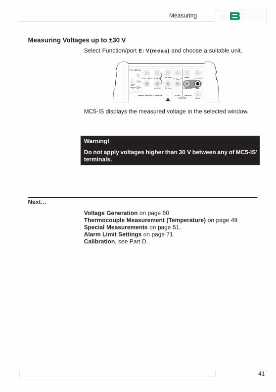
Measuring Voltages up to ±30 VSelect Function/port E: V(meas) and choose a suitable unit.
MC5-IS displays the measured voltage in the selected window.
Warning!
Do not apply voltages higher than 30 V between any of MC5-IS’terminals.
Next…
Voltage Generation on page 60Thermocouple Measurement (Temperature) on page 49Special Measurements on page 51.Alarm Limit Settings on page 71.Calibration, see Part D.
� � � � � � � � �� � � � � � � � � � � � � �
� � � � � � � �
� � � � � � � � � � �� � � �
� � �
� � � �
� � �
� � � � � � �� � �
� � �
� � � � � � � � � � � �
� � � � � � � � � � � � � � � � � � � � � � � � � �
� � � � � � � �
� � � � � ! � � �
� " � � � � ! # � � $
� � � �
$ � � % �
& � � '
! � � � � � �
( � � � � � �� � � � � � � � � � �
Measuring
42
Startup and Basic Operation
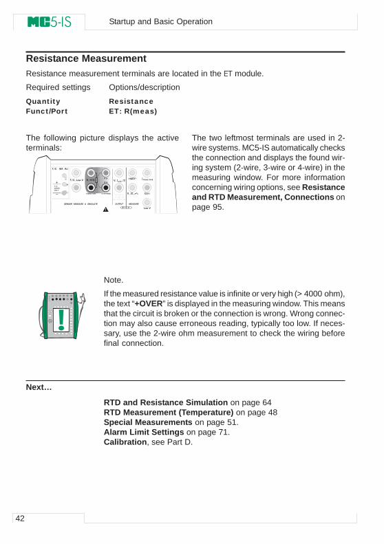
Resistance MeasurementResistance measurement terminals are located in the ET module.
Required settings Options/description
Quantity ResistanceFunct/Port ET: R(meas)
The following picture displays the activeterminals:
The two leftmost terminals are used in 2-wire systems. MC5-IS automatically checksthe connection and displays the found wir-ing system (2-wire, 3-wire or 4-wire) in themeasuring window. For more informationconcerning wiring options, see Resistanceand RTD Measurement, Connections onpage 95.
Note.
If the measured resistance value is infinite or very high (> 4000 ohm),the text “+OVER” is displayed in the measuring window. This meansthat the circuit is broken or the connection is wrong. Wrong connec-tion may also cause erroneous reading, typically too low. If neces-sary, use the 2-wire ohm measurement to check the wiring beforefinal connection.
Next…
RTD and Resistance Simulation on page 64RTD Measurement (Temperature) on page 48Special Measurements on page 51.Alarm Limit Settings on page 71.Calibration, see Part D.
� � � � � � � � �� � � � � � � � � � � � � �
� � � � � � � �
� � � � � � � � � � �� � � �
� � �
� � � �
� � �
� � � � � � �� � �
� � �
� � � � � � � � � � � �
� � � � � � � � � � � � � � � � � � � � � � � � � �
� � � � � � � �
� � � � � ! � � �
� " � � � � ! # � � $
� � � �
$ � � % �
& � � '
! � � � � � �
( � � � � � �� � � � � � � �
� � � �( �
! �
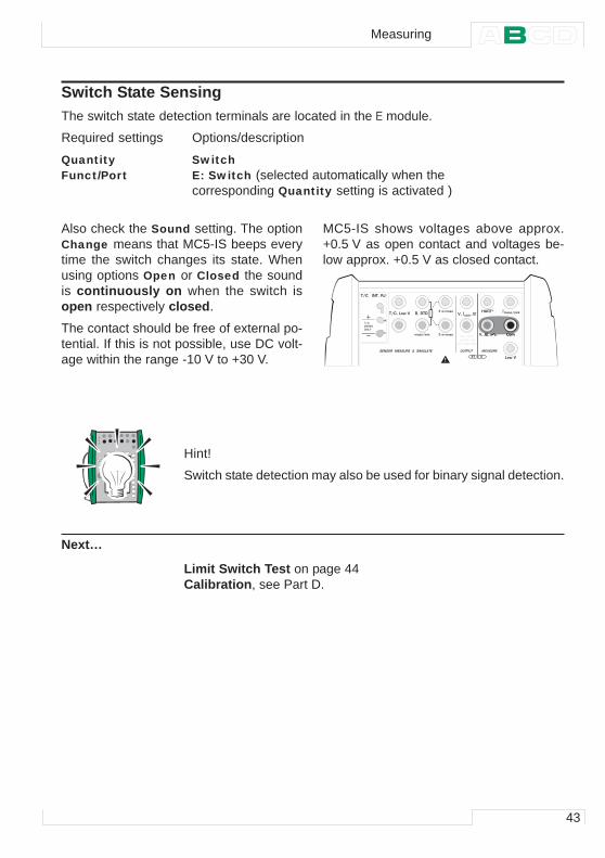
43
Switch State SensingThe switch state detection terminals are located in the E module.
Required settings Options/description
Quantity SwitchFunct/Port E: Switch (selected automatically when the
corresponding Quantity setting is activated )
Also check the Sound setting. The optionChange means that MC5-IS beeps everytime the switch changes its state. Whenusing options Open or Closed the soundis continuously on when the switch isopen respectively closed.
The contact should be free of external po-tential. If this is not possible, use DC volt-age within the range -10 V to +30 V.
MC5-IS shows voltages above approx.+0.5 V as open contact and voltages be-low approx. +0.5 V as closed contact.
Hint!
Switch state detection may also be used for binary signal detection.
Next…
Limit Switch Test on page 44Calibration, see Part D.
� � � � � � � � �� � � � � � � � � � � � � �
� � � � � � � �
� � � � � � � � � � �� � � �
� � �
� � � �
� � �
� � � � � � �� � �
� � �
� � � � � � � � � � � �
� � � � � � � � � � � � � � � � � � � � � � � � � �
� � � � � � � �
� � � � � ! � � �
� " � � � � ! # � � $
� � � �
$ � � % �
& � � '
! � � � � � �
( � � � � � �� � � � � � � � � � �
Measuring
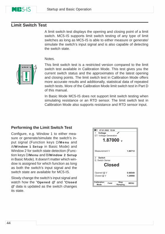
44
Startup and Basic Operation
Limit Switch TestA limit switch test displays the opening and closing point of a limitswitch. MC5-IS supports limit switch testing of any type of limitswitches as long as MC5-IS is able to either measure or generate/simulate the switch’s input signal and is also capable of detectingthe switch state.
Notes.
This limit switch test is a restricted version compared to the limitswitch test available in Calibration Mode. This test gives you thecurrent switch status and the approximates of the latest openingand closing points. The limit switch test in Calibration Mode offersmore accurate results and additionally, statistical data of repeatedswitch tests. More of the Calibration Mode limit switch test in Part Dof this manual.
In Basic Mode MC5-IS does not support limit switch testing whensimulating resistance or an RTD sensor. The limit switch test inCalibration Mode also supports resistance and RTD sensor input.
Performing the Limit Switch TestConfigure, e.g. Window 1 to either mea-sure or generate/simulate the switch’s in-put signal (Function keys D/Menu andA/Window 1 Setup in Basic Mode) andWindow 2 for switch state detection (Func-tion keys D/Menu and B/Window 2 Setupin Basic Mode). It doesn’t matter which win-dow is assigned for which function as longas both the switch’s input signal and theswitch state are available for MC5-IS.
Slowly change the switch’s input signal andwatch how the “Opened @” and “Closed@” data is updated as the switch changesits state.
� % � � � � � � � � � � � � � $ �
� � � � � * � � � � � �
� � � � � + , � � �
� � � ' � � � � & � � ( � � � � � � �
� � � � � � � ) � � � � �
� � � � � � � � � � '
*� � � % � � �
" � � � � �
� � � �" � � # � � � � �
- � � . � �+ � � . � & ' (
* + � � � � , � '
� � � � � � � , � '
� � � � % � �
� � / � � $ /
� � � / / / �
0 � � �
45
Note.
The accuracy of the “Opened @” and “Closed @” values dependgreatly on the change rate of the switch’s input signal.
Hint.
If you use MC5-IS to generate/simulate the switch’s input signal,you can use ramping to create changing input signals for the switchunder test.
Where to find more information when measuring a switch’s input signal…
Pressure Measurement on page 37Using External Modules on page 37Voltage Measurement on page 40Current Measurement on page 39Thermocouple Measurement (Temperature) on page 49RTD Measurement (Temperature) on page 48
Where to find more information when generating a switch’s input signal…
Voltage Generation on page 60Current Sink on page 58Thermocouple Simulation on page 65Ramping on page 69
Measuring
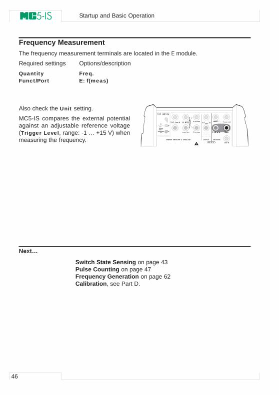
46
Startup and Basic Operation
Frequency MeasurementThe frequency measurement terminals are located in the E module.
Required settings Options/description
Quantity Freq.Funct/Port E: f(meas)
Also check the Unit setting.
MC5-IS compares the external potentialagainst an adjustable reference voltage(Trigger Level, range: -1 … +15 V) whenmeasuring the frequency.
Next…
Switch State Sensing on page 43Pulse Counting on page 47Frequency Generation on page 62Calibration, see Part D.
� � � � � � � � �� � � � � � � � � � � � � �
� � � � � � � �
� � � � � � � � � � �� � � �
� � �
� � � �
� � �
� � � � � � �� � �
� � �
� � � � � � � � � � � �
� � � � � � � � � � � � � � � � � � � � � � � � � �
� � � � � � � �
� � � � � ! � � �
� " � � � � ! # � � $
� � � �
$ � � % �
& � � '
! � � � � � �
( � � � � � �� � � � � � � � � � �
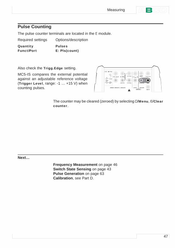
47
Pulse CountingThe pulse counter terminals are located in the E module.
Required settings Options/description
Quantity PulsesFunct/Port E: Pls(count)
Also check the Trigg.Edge setting.
MC5-IS compares the external potentialagainst an adjustable reference voltage(Trigger Level, range: -1 … +15 V) whencounting pulses.
The counter may be cleared (zeroed) by selecting D/Menu, 6/Clearcounter.
Next…
Frequency Measurement on page 46Switch State Sensing on page 43Pulse Generation on page 63Calibration, see Part D.
� � � � � � � � �� � � � � � � � � � � � � �
� � � � � � � �
� � � � � � � � � � �� � � �
� � �
� � � �
� � �
� � � � � � �� � �
� � �
� � � � � � � � � � � �
� � � � � � � � � � � � � � � � � � � � � � � � � �
� � � � � � � �
� � � � � ! � � �
� " � � � � ! # � � $
� � � �
$ � � % �
& � � '
! � � � � � �
( � � � � � �� � � � � � � � � � �
Measuring
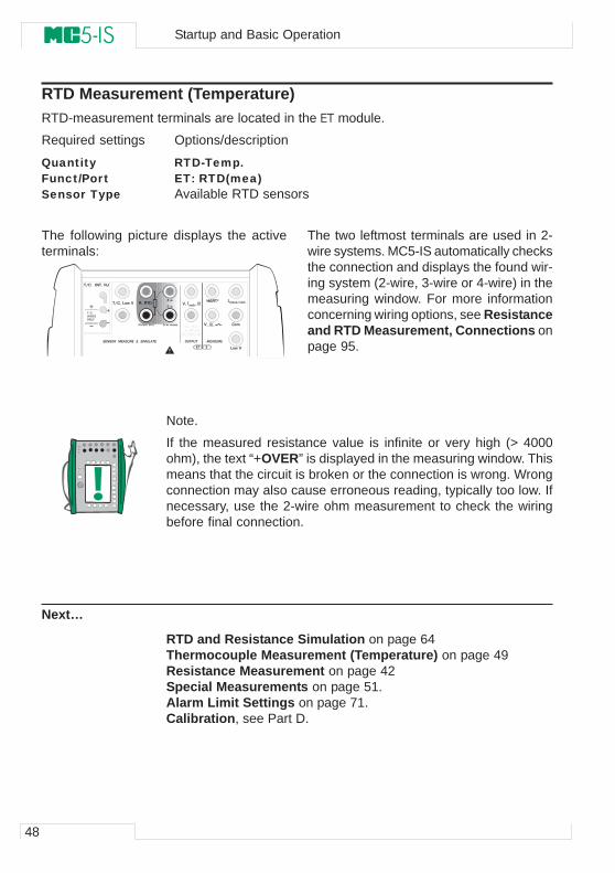
48
Startup and Basic Operation
RTD Measurement (Temperature)RTD-measurement terminals are located in the ET module.
Required settings Options/description
Quantity RTD-Temp.Funct/Port ET: RTD(mea)Sensor Type Available RTD sensors
The following picture displays the activeterminals:
The two leftmost terminals are used in 2-wire systems. MC5-IS automatically checksthe connection and displays the found wir-ing system (2-wire, 3-wire or 4-wire) in themeasuring window. For more informationconcerning wiring options, see Resistanceand RTD Measurement, Connections onpage 95.
Note.
If the measured resistance value is infinite or very high (> 4000ohm), the text “+OVER” is displayed in the measuring window. Thismeans that the circuit is broken or the connection is wrong. Wrongconnection may also cause erroneous reading, typically too low. Ifnecessary, use the 2-wire ohm measurement to check the wiringbefore final connection.
Next…
RTD and Resistance Simulation on page 64Thermocouple Measurement (Temperature) on page 49Resistance Measurement on page 42Special Measurements on page 51.Alarm Limit Settings on page 71.Calibration, see Part D.
� � � � � � � � �� � � � � � � � � � � � � �
� � � � � � � �
� � � � � � � � � � �� � � �
� � �
� � � �
� � �
� � � � � � �� � �
� � �
� � � � � � � � � � � �
� � � � � � � � � � � � � � � � � � � � � � � � � �
� � � � � � � �
� � � � � ! � � �
� " � � � � ! # � � $
� � � �
$ � � % �
& � � '
! � � � � � �
( � � � � � �� � � � � � � �
� � � �( �
! �
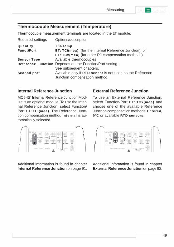
49
Thermocouple Measurement (Temperature)Thermocouple measurement terminals are located in the ET module.
Required settings Options/description
Quantity T/C-TempFunct/Port ET: TCi(mea) (for the internal Reference Junction), or
ET: TCx(mea) (for other RJ compensation methods)Sensor Type Available thermocouplesReference Junction Depends on the Function/Port setting.
See subsequent chapters.Second port Available only if RTD sensor is not used as the Reference
Junction compensation method.
Internal Reference JunctionMC5-IS’ Internal Reference Junction Mod-ule is an optional module. To use the Inter-nal Reference Junction, select Function/Port ET: TCi(mea). The Reference Junc-tion compensation method Internal is au-tomatically selected.
External Reference JunctionTo use an External Reference Junction,select Function/Port ET: TCx(mea) andchoose one of the available ReferenceJunction compensation methods: Entered,0°C or available RTD sensors.
Additional information is found in chapterInternal Reference Junction on page 91.
Additional information is found in chapterExternal Reference Junction on page 92.
� � � � � � � � �� � � � � � � � � � � � � �
� � � � � � � �
� � � � � � � � � � �� � � �
� � �
� � � �
� � �
� � � � � � �� � �
� � �
� � � � � � � � � � � �
� � � � � � � � � � � � � � � � � � � � � � � � � �
� � � � � � � �
� � � � � ! � � �
� " � � � � ! # � � $
� � � �
$ � � % �
& � � '
! � � � � � �
( � � � � � �� � � � � � � �
� � � �
$ � � % �
& � � '
� � � � � � � � �� � � � � � � � � � � � � �
� � � � � � � �
� � � � � � � � � � �� � � �
� � �
� � � �
� � �
� � � � � � �� � �
� � �
� � � � � � � � � � � �
� � � � � � � � � � � � � � � � � � � � � � � � � �
� � � � � � � �
� � � � � ! � � �
� " � � � � ! # � � $
� � � �
$ � � % �
& � � '
! � � � � � �
( � � � � � �� � � � � � � �
� � � � � � � � �
Measuring
50
Startup and Basic Operation
Note.
MC5-IS has a comprehensive set of predefined sensor types. Addi-tional sensor types are available as options.
Warning!
If you connect an RTD sensor to the ET module’s R, RTD con-nectors, there is no galvanic isolation between the thermo-couple and the RTD sensor.
Next…
Thermocouple Simulation on page 65RTD Measurement (Temperature) on page 48Voltage Measurement on page 40Special Measurements on page 51.Alarm Limit Settings on page 71.Calibration, see Part D.
Problems with thermovoltage measurement? See Error situationson page 94.
51
Special Measurements
Special measurements are extra utilities that can be activated toperform a special function alongside the normal measurement.
Only one of the special measurements may be activated at a giventime for each window/quantity. Activating another special measure-ment deactivates the earlier special measurement in the same win-dow (or the earlier special measurement using the same quantity).
All special measurements are started similarly:
• Select D/Menu and when necessary, B/Window 2 Setup.
• As the special measurement setting command is located inthe window setup’s submenu, select either the numerical key
or the cursor key to open the submenu.
• Then select 1/Spec ial Measurements and the type of spe-cial measurement from the provided pop-up list (or deactivatea special measurement by selecting the option “None”).
Some of the special measurements do not require any additionalinformation. They start immediately after they are activated. Rateof Change Measurement, Special Filtering and Resolution, Re-dundant Measurement and Deviation Measurement do howeverneed some additional information. Therefore when you activate themyou will have to enter the required additional information before thespecial measurement is started.
Notes.
Special measurements are only available in Basic Mode.
If you change any of the main settings of the measurement (Quan-tity, Funct/Port), the defined special measurement is deactivated.
To zero/restart a special measurement without altering any mainmeasurement settings, do the same menu commands you used forstarting the special measurement.
Special Measurements
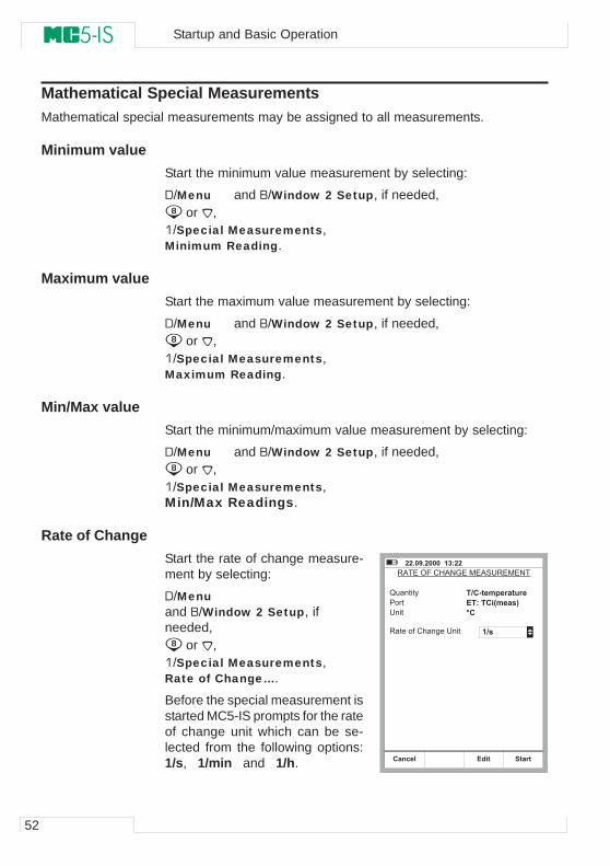
52
Startup and Basic Operation
Mathematical Special MeasurementsMathematical special measurements may be assigned to all measurements.
Minimum valueStart the minimum value measurement by selecting:
D/Menu and B/Window 2 Setup, if needed, or ,
1/Special Measurements,Minimum Reading.
Maximum valueStart the maximum value measurement by selecting:
D/Menu and B/Window 2 Setup, if needed, or ,
1/Special Measurements,Maximum Reading.
Min/Max valueStart the minimum/maximum value measurement by selecting:
D/Menu and B/Window 2 Setup, if needed, or ,
1/Special Measurements,Min/Max Readings.
Rate of ChangeStart the rate of change measure-ment by selecting:
D/Menuand B/Window 2 Setup, ifneeded,
or ,1/Special Measurements,Rate of Change….
Before the special measurement isstarted MC5-IS prompts for the rateof change unit which can be se-lected from the following options:1/s, 1/min and 1/h.
� � � � / � � � � � � � � � � �
- . � � * / � � 0 . � ( � � . � 1 - � � �
2 � � � � 3
� � � �
1 � �
- � � � � � 4 � � ) � & � � 1 � �
1 2 " 3 � � � . � � � � � � �& 1 � 1 " 4 � � � � 56 "
� 2 �
+ � � � �" � � � � � & � �
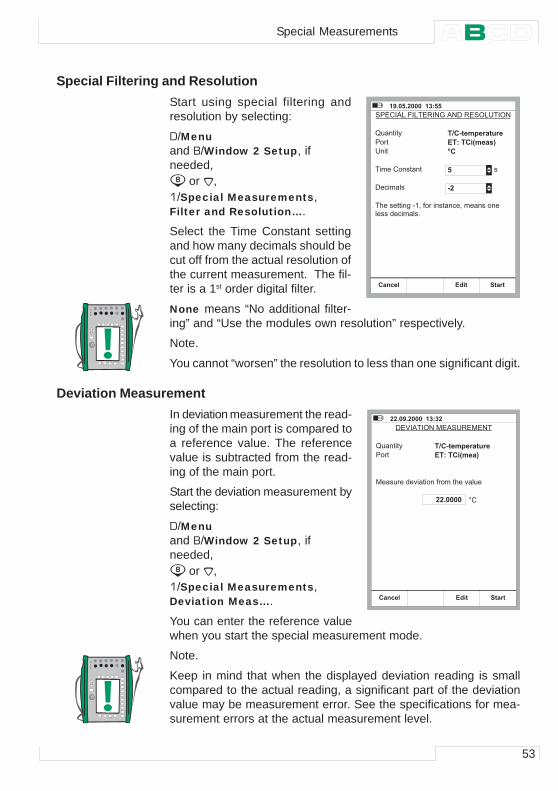
53
Special Filtering and ResolutionStart using special filtering andresolution by selecting:
D/Menuand B/Window 2 Setup, ifneeded,
or ,1/Special Measurements,Filter and Resolution….
Select the Time Constant settingand how many decimals should becut off from the actual resolution ofthe current measurement. The fil-ter is a 1st order digital filter.
None means “No additional filter-ing” and “Use the modules own resolution” respectively.
Note.
You cannot “worsen” the resolution to less than one significant digit.
Deviation MeasurementIn deviation measurement the read-ing of the main port is compared toa reference value. The referencevalue is subtracted from the read-ing of the main port.
Start the deviation measurement byselecting:
D/Menuand B/Window 2 Setup, ifneeded,
or ,1/Special Measurements,Deviation Meas….
You can enter the reference valuewhen you start the special measurement mode.
Note.
Keep in mind that when the displayed deviation reading is smallcompared to the actual reading, a significant part of the deviationvalue may be measurement error. See the specifications for mea-surement errors at the actual measurement level.
� / � � � � � � � � � � � � � �
� � � � . 5 � / � 5 � - � � ( � . � 6 � - � * 5 1 � � * �
2 � � � � 3
� � � �
1 � �
� � � � � � � � � � �
1 2 " 3 � � � . � � � � � � �& 1 � 1 " 4 � � � � 56 "
6 � � � � � � � 3 �
� ) � � � � � � � & � " � 7 � 4 � � � � � � � � � 7 � � � � � � � �� � � � � � � � � � � � � � �
� �
+ � � � �" � � � � � & � �
� � � � / � � � � � � � � �
6 ' � . � � * � � � . � 1 - � � �
2 � � � � 3
� � � �
� � � � � � � � � � � � � � � � 4 � � � � � ) � � � � � �
1 2 " 3 � � � . � � � � � � �& 1 � 1 " 4 � � � 5
� � � � � � � 8 �
+ � � � �" � � � � � & � �
Special Measurements
54
Startup and Basic Operation
Special Measurements Using Two Ports SimultaneouslyThe following special measurements only apply when two ports aresimultaneously used in the same window. The Second Port set-ting in the window’s setup menu allows you to select another portfor the same window. The Second Port setting is enabled depend-ing on selected quantity and available modules.
Difference MeasurementIn difference measurement the difference between the reading ofthe main port and the second port is calculated. The reading of thesecond port is subtracted from the reading of the main port.
Start the difference measurement by selecting:
D/Menu and B/Window 2 Setup, if needed, or ,
1/Special Measurement,Difference Meas….
Notes.
Difference measurement is not available as an option in the list ofspecial measurements, unless two measurement ports are activatedin the same window.
No setting window appears, but the calculated difference is dis-played in the special measurement row.
The measurement value of the second port may be assigned to theExtra Info row at the bottom of the window.
Keep in mind that when the displayed difference reading is smallcompared to the actual reading, a significant part of the differ-ence value may be measurement error. See the specificationsfor measurement errors at the actual measurement level.If the measuring spans of the selected ports are different, makesure you do not exceed the measurement range of either port.
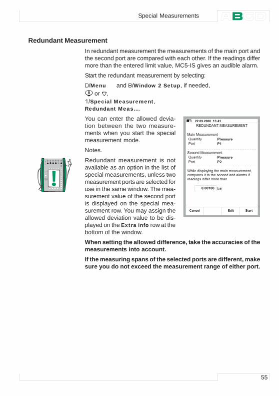
55
Redundant MeasurementIn redundant measurement the measurements of the main port andthe second port are compared with each other. If the readings differmore than the entered limit value, MC5-IS gives an audible alarm.
Start the redundant measurement by selecting:
D/Menu and B/Window 2 Setup, if needed, or ,
1/Special Measurement,Redundant Meas….
You can enter the allowed devia-tion between the two measure-ments when you start the specialmeasurement mode.
Notes.
Redundant measurement is notavailable as an option in the list ofspecial measurements, unless twomeasurement ports are selected foruse in the same window. The mea-surement value of the second portis displayed on the special mea-surement row. You may assign theallowed deviation value to be dis-played on the Extra info row at thebottom of the window.
When setting the allowed difference, take the accuracies of themeasurements into account.If the measuring spans of the selected ports are different, makesure you do not exceed the measurement range of either port.
� � � � / � � � � � � � � $ �
- 6 1 � 6 . � � � � . � 1 - � � �
� � � � � � � � � � � � �
2 � � � � 3 ! � � � � � � �
� � � � � � � � � �
� � � � ! �
� � � � � � � � � � � � � � �
2 � � � � 3 ! � � � � � � �� � � � ! �
9 ) � � � � � � � + � � 3 � & � � ) � � � � � � � � � � � � � � � 7 �� � � + � � � � � � � � � � � � ) � � � � � � � � � � � � � � � � � � � 4 �� � � � � & � � � � 4 4 � � � � � � � � � ) � �
+ � � � �" � � � � � & � �
Special Measurements
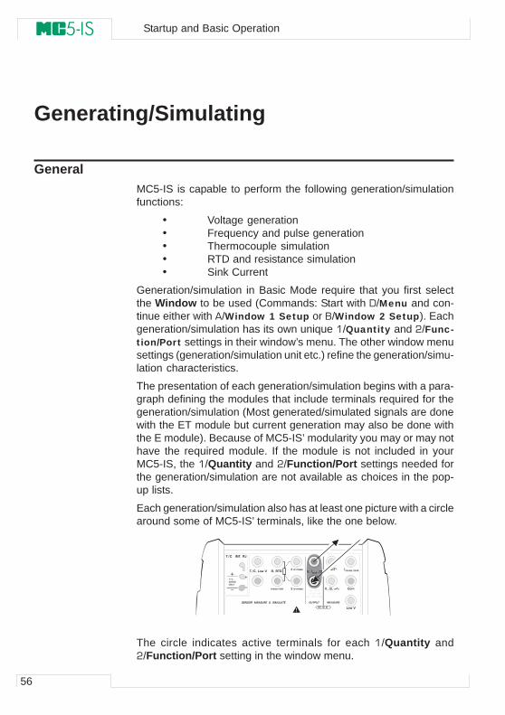
56
Startup and Basic Operation
Generating/Simulating
GeneralMC5-IS is capable to perform the following generation/simulationfunctions:
• Voltage generation• Frequency and pulse generation• Thermocouple simulation• RTD and resistance simulation• Sink Current
Generation/simulation in Basic Mode require that you first selectthe Window to be used (Commands: Start with D/Menu and con-tinue either with A/Window 1 Setup or B/Window 2 Setup). Eachgeneration/simulation has its own unique 1/Quantity and 2/Func-tion/Port settings in their window’s menu. The other window menusettings (generation/simulation unit etc.) refine the generation/simu-lation characteristics.
The presentation of each generation/simulation begins with a para-graph defining the modules that include terminals required for thegeneration/simulation (Most generated/simulated signals are donewith the ET module but current generation may also be done withthe E module). Because of MC5-IS’ modularity you may or may nothave the required module. If the module is not included in yourMC5-IS, the 1/Quantity and 2/Function/Port settings needed forthe generation/simulation are not available as choices in the pop-up lists.
Each generation/simulation also has at least one picture with a circlearound some of MC5-IS’ terminals, like the one below.
The circle indicates active terminals for each 1/Quantity and2/Function/Port setting in the window menu.
� � � � � � � � �� � � � � � � � � � � � � �
� � � � � � � �
� � � � � � � � � � �� � � �
� � �
� � � �
� � �
� � � � � � �� � �
� � �
� � � � � � � � � � � �
� � � � � � � � � � � � � � � � � � � � � � � � � �
� � � � � � � �
� � � � � ! � � �
� " � � � � ! # � � $
� � � �
$ � � % �
& � � '
! � � � � � �
( � � � � � �� � � � � � � �
� � � � � � � � � � � � � � �
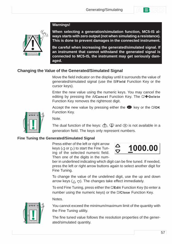
57
Warnings!
When selecting a generation/simulation function, MC5-IS al-ways starts with zero output (not when simulating a resistance).This is done to prevent damages in the connected instrument.
Be careful when increasing the generated/simulated signal. Ifan instrument that cannot withstand the generated signal isconnected to MC5-IS, the instrument may get seriously dam-aged.
Changing the Value of the Generated/Simulated SignalMove the field indicator on the display until it surrounds the value ofgenerated/simulated signal (use the B/Field Function Key or thecursor keys).
Enter the new value using the numeric keys. You may cancel theediting by pressing the A/Cancel Function Key. The C/ DeleteFunction Key removes the rightmost digit.
Accept the new value by pressing either the key or the D/OKFunction Key.
Note.
The dual function of the keys: , and is not available in ageneration field. The keys only represent numbers.
Fine Tuning the Generated/Simulated SignalPress either of the left or right arrowkeys ( or ) to start the Fine Tun-ing of the selected numeric field.Then one of the digits in the num-ber in underlined indicating which digit can be fine tuned. If needed,press the left or right arrow buttons again to select another digit forFine Tuning.
To change the value of the undelined digit, use the up and downarrow keys ( ). The changes take effect immediately.
To end Fine Tuning, press either the C/Edit Function Key (to enter anumber using the numeric keys) or the D/Close Function Key.
Notes.
You cannot exceed the minimum/maximum limit of the quantity withthe Fine Tuning utility.
The fine tuned value follows the resolution properties of the gener-ated/simulated quantity.
� � � � � � �
Generating/Simulating
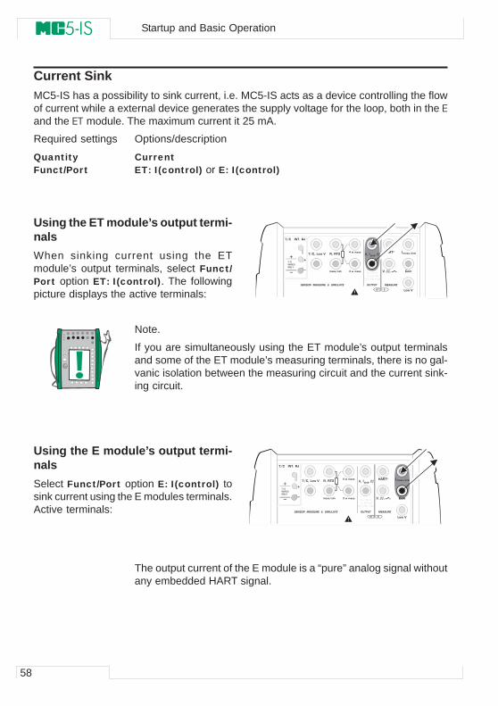
58
Startup and Basic Operation
Current SinkMC5-IS has a possibility to sink current, i.e. MC5-IS acts as a device controlling the flowof current while a external device generates the supply voltage for the loop, both in the Eand the ET module. The maximum current it 25 mA.
Required settings Options/description
Quantity CurrentFunct/Port ET: I(control) or E: I(control)
Using the ET module’s output termi-nalsWhen sinking current using the ETmodule’s output terminals, select Funct/Port option ET: I(control). The followingpicture displays the active terminals:
Note.
If you are simultaneously using the ET module’s output terminalsand some of the ET module’s measuring terminals, there is no gal-vanic isolation between the measuring circuit and the current sink-ing circuit.
Using the E module’s output termi-nalsSelect Funct/Port option E: I(control) tosink current using the E modules terminals.Active terminals:
Note.
The output current of the E module is a “pure” analog signal withoutany embedded HART signal.
� � � � � � � � �� � � � � � � � � � � � � �
� � � � � � � �
� � � � � � � � � � �� � � �
� � �
� � � �
� � �
� � � � � � �� � �
� � �
� � � � � � � � � � � �
� � � � � � � � � � � � � � � � � � � � � � � � � �
� � � � � � � �
� � � � � ! � � �
� " � � � � ! # � � $
� � � �
$ � � % �
& � � '
! � � � � � �
( � � � � � �� � � � � � � �
� � � � � � � � � � � � � � �
� � � � � � � � �� � � � � � � � � � � � � �
� � � � � � � �
� � � � � � � � � � �� � � �
� � �
� � � �
� � �
� � � � � � �� � �
� � �
� � � � � � � � � � � �
� � � � � � � � � � � � � � � � � � � � � � � � � �
� � � � � � � �
� � � � � ! � � �
� " � � � � ! # � � $
� � � �
$ � � % �
& � � '
! � � � � � �
( � � � � � �� � � � � � � �
� � � � � � � � � �
� � �
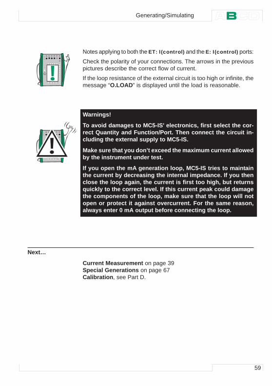
59
Notes applying to both the ET: I(control) and the E: I(control) ports:
Check the polarity of your connections. The arrows in the previouspictures describe the correct flow of current.
If the loop resistance of the external circuit is too high or infinite, themessage “O.LOAD” is displayed until the load is reasonable.
Warnings!
To avoid damages to MC5-IS' electronics, first select the cor-rect Quantity and Function/Port. Then connect the circuit in-cluding the external supply to MC5-IS.
Make sure that you don’t exceed the maximum current allowedby the instrument under test.
If you open the mA generation loop, MC5-IS tries to maintainthe current by decreasing the internal impedance. If you thenclose the loop again, the current is first too high, but returnsquickly to the correct level. If this current peak could damagethe components of the loop, make sure that the loop will notopen or protect it against overcurrent. For the same reason,always enter 0 mA output before connecting the loop.
Next…
Current Measurement on page 39Special Generations on page 67Calibration, see Part D.
Generating/Simulating
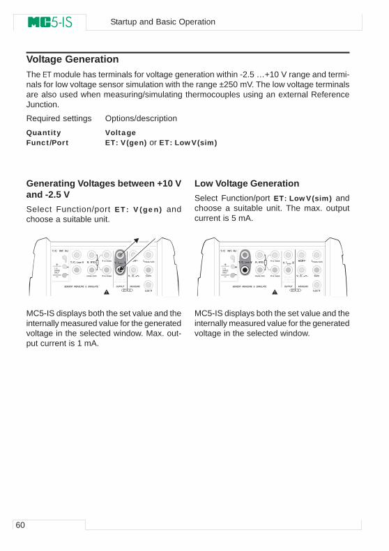
60
Startup and Basic Operation
Voltage GenerationThe ET module has terminals for voltage generation within -2.5 …+10 V range and termi-nals for low voltage sensor simulation with the range ±250 mV. The low voltage terminalsare also used when measuring/simulating thermocouples using an external ReferenceJunction.
Required settings Options/description
Quantity VoltageFunct/Port ET: V(gen) or ET: LowV(sim)
Generating Voltages between +10 Vand -2.5 VSelect Function/port ET: V(gen) andchoose a suitable unit.
MC5-IS displays both the set value and theinternally measured value for the generatedvoltage in the selected window. Max. out-put current is 1 mA.
Low Voltage GenerationSelect Function/port ET: LowV(sim) andchoose a suitable unit. The max. outputcurrent is 5 mA.
MC5-IS displays both the set value and theinternally measured value for the generatedvoltage in the selected window.
� � � � � � � � �� � � � � � � � � � � � � �
� � � � � � � �
� � � � � � � � � � �� � � �
� � �
� � � �
� � �
� � � � � � �� � �
� � �
� � � � � � � � � � � �
� � � � � � � � � � � � � � � � � � � � � � � � � �
� � � � � � � �
� � � � � ! � � �
� " � � � � ! # � � $
� � � �
$ � � % �
& � � '
! � � � � � �
( � � � � � �� � � � � � � �
� � � � � � � � �� � � � � � � � �� � � � � � � � � � � � � �
� � � � � � � �
� � � � � � � � � � �� � � �
� � �
� � � �
� � �
� � � � � � �� � �
� � �
� � � � � � � � � � � �
� � � � � � � � � � � � � � � � � � � � � � � � � �
� � � � � � � �
� � � � � ! � � �
� " � � � � ! # � � $
� � � �
$ � � % �
& � � '
! � � � � � �
( � � � � � �� � � � � � � �
� � � � � � � � � � � � � � �
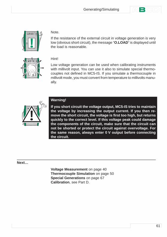
61
Note.
If the resistance of the external circuit in voltage generation is verylow (obvious short circuit), the message “O.LOAD” is displayed untilthe load is reasonable.
Hint!
Low voltage generation can be used when calibrating instrumentswith millivolt input. You can use it also to simulate special thermo-couples not defined in MC5-IS. If you simulate a thermocouple inmillivolt mode, you must convert from temperature to millivolts manu-ally.
Warning!
If you short circuit the voltage output, MC5-IS tries to maintainthe voltage by increasing the output current. If you then re-move the short circuit, the voltage is first too high, but returnsquickly to the correct level. If this voltage peak could damagethe components of the circuit, make sure that the circuit cannot be shorted or protect the circuit against overvoltage. Forthe same reason, always enter 0 V output before connectingthe circuit.
Next…
Voltage Measurement on page 40Thermocouple Simulation on page 50Special Generations on page 67Calibration, see Part D.
Generating/Simulating
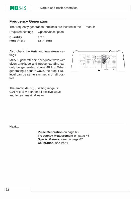
62
Startup and Basic Operation
Frequency GenerationThe frequency generation terminals are located in the ET module.
Required settings Options/description
Quantity Freq.Funct/Port ET: f(gen)
Also check the Unit and Waveform set-tings.
MC5-IS generates sine or square wave withgiven amplitude and frequency. Sine canonly be generated above 40 Hz. Whengenerating a square wave, the output DC-level can be set to symmetric or all posi-tive.
The amplitude (Vpp) setting range is:0.01 V to 5 V both for all positive waveand for symmetrical wave.
Next…
Pulse Generation on page 63Frequency Measurement on page 46Special Generations on page 67Calibration, see Part D.
� � � � � � � � �� � � � � � � � � � � � � �
� � � � � � � �
� � � � � � � � � � �� � � �
� � �
� � � �
� � �
� � � � � � �� � �
� � �
� � � � � � � � � � � �
� � � � � � � � � � � � � � � � � � � � � � � � � �
� � � � � � � �
� � � � � ! � � �
� " � � � � ! # � � $
� � � �
$ � � % �
& � � '
! � � � � � �
( � � � � � �� � � � � � � �
� � � � � � � � � � � � � � �
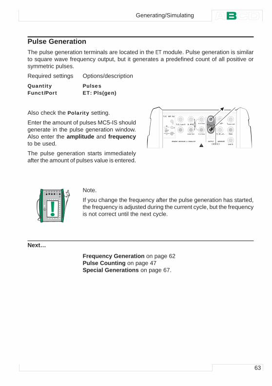
63
Pulse GenerationThe pulse generation terminals are located in the ET module. Pulse generation is similarto square wave frequency output, but it generates a predefined count of all positive orsymmetric pulses.
Required settings Options/description
Quantity PulsesFunct/Port ET: Pls(gen)
Also check the Polarity setting.
Enter the amount of pulses MC5-IS shouldgenerate in the pulse generation window.Also enter the amplitude and frequencyto be used.
The pulse generation starts immediatelyafter the amount of pulses value is entered.
Note.
If you change the frequency after the pulse generation has started,the frequency is adjusted during the current cycle, but the frequencyis not correct until the next cycle.
Next…
Frequency Generation on page 62Pulse Counting on page 47Special Generations on page 67.
� � � � � � � � �� � � � � � � � � � � � � �
� � � � � � � �
� � � � � � � � � � �� � � �
� � �
� � � �
� � �
� � � � � � �� � �
� � �
� � � � � � � � � � � �
� � � � � � � � � � � � � � � � � � � � � � � � � �
� � � � � � � �
� � � � � ! � � �
� " � � � � ! # � � $
� � � �
$ � � % �
& � � '
! � � � � � �
( � � � � � �� � � � � � � �
� � � � � � � � � � � � � � �
Generating/Simulating
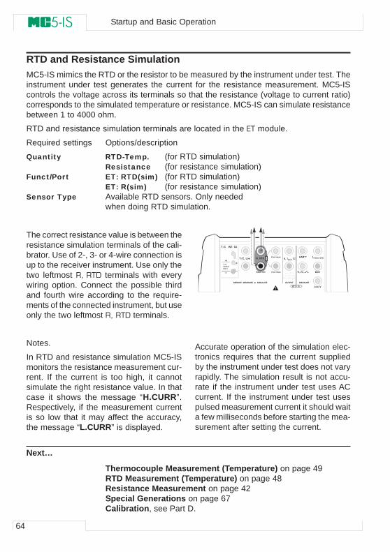
64
Startup and Basic Operation
RTD and Resistance SimulationMC5-IS mimics the RTD or the resistor to be measured by the instrument under test. Theinstrument under test generates the current for the resistance measurement. MC5-IScontrols the voltage across its terminals so that the resistance (voltage to current ratio)corresponds to the simulated temperature or resistance. MC5-IS can simulate resistancebetween 1 to 4000 ohm.
RTD and resistance simulation terminals are located in the ET module.
Required settings Options/description
Quantity RTD-Temp. (for RTD simulation)Resistance (for resistance simulation)
Funct/Port ET: RTD(sim) (for RTD simulation)ET: R(sim) (for resistance simulation)
Sensor Type Available RTD sensors. Only neededwhen doing RTD simulation.
The correct resistance value is between theresistance simulation terminals of the cali-brator. Use of 2-, 3- or 4-wire connection isup to the receiver instrument. Use only thetwo leftmost R, RTD terminals with everywiring option. Connect the possible thirdand fourth wire according to the require-ments of the connected instrument, but useonly the two leftmost R, RTD terminals.
Notes.
In RTD and resistance simulation MC5-ISmonitors the resistance measurement cur-rent. If the current is too high, it cannotsimulate the right resistance value. In thatcase it shows the message “H.CURR”.Respectively, if the measurement currentis so low that it may affect the accuracy,the message “L.CURR” is displayed.
Accurate operation of the simulation elec-tronics requires that the current suppliedby the instrument under test does not varyrapidly. The simulation result is not accu-rate if the instrument under test uses ACcurrent. If the instrument under test usespulsed measurement current it should waita few milliseconds before starting the mea-surement after setting the current.
Next…
Thermocouple Measurement (Temperature) on page 49RTD Measurement (Temperature) on page 48Resistance Measurement on page 42Special Generations on page 67Calibration, see Part D.
� � � � � � � � �� � � � � � � � � � � � � �
� � � � � � � �
� � � � � � � � � � �� � � �
� � �
� � � �
� � �
� � � � � � �� � �
� � �
� � � � � � � � � � � �
� � � � � � � � � � � � � � � � � � � � � � � � � �
� � � � � � � �
� � � � � ! � � �
� " � � � � ! # � � $
� � � �
$ � � % �
& � � '
! � � � � � �
( � � � � � �� � � � � � � �
� � � �
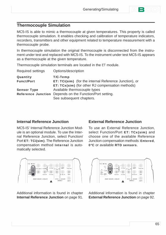
65
Thermocouple SimulationMC5-IS is able to mimic a thermocouple at given temperatures. This property is calledthermocouple simulation. It enables checking and calibration of temperature indicators,recorders, transmitters and other equipment related to temperature measurement with athermocouple probe.
In thermocouple simulation the original thermocouple is disconnected from the instru-ment under test and replaced with MC5-IS. To the instrument under test MC5-IS appearsas a thermocouple at the given temperature.
Thermocouple simulation terminals are located in the ET module.
Required settings Options/description
Quantity T/C-TempFunct/Port ET: TCi(sim) (for the internal Reference Junction), or
ET: TCx(sim) (for other RJ compensation methods)Sensor Type Available thermocouple typesReference Junction Depends on the Function/Port setting.
See subsequent chapters.
Internal Reference JunctionMC5-IS’ Internal Reference Junction Mod-ule is an optional module. To use the Inter-nal Reference Junction, select Function/Port ET: TCi(sim). The Reference Junctioncompensation method Internal is auto-matically selected.
External Reference JunctionTo use an External Reference Junction,select Function/Port ET: TCx(sim) andchoose one of the available ReferenceJunction compensation methods: Entered,0°C or available RTD sensors.
Additional information is found in chapterInternal Reference Junction on page 91.
Additional information is found in chapterExternal Reference Junction on page 92.
� � � � � � � � �� � � � � � � � � � � � � �
� � � � � � � �
� � � � � � � � � � �� � � �
� � �
� � � �
� � �
� � � � � � �� � �
� � �
� � � � � � � � � � � �
� � � � � � � � � � � � � � � � � � � � � � � � � �
� � � � � � � �
� � � � � ! � � �
� " � � � � ! # � � $
� � � �
$ � � % �
& � � '
! � � � � � �
( � � � � � �� � � � � � � �
� � � �
$ � � % �
& � � '
� � � � � � � � �� � � � � � � � � � � � � �
� � � � � � � �
� � � � � � � � � � �� � � �
� � �
� � � �
� � �
� � � � � � �� � �
� � �
� � � � � � � � � � � �
� � � � � � � � � � � � � � � � � � � � � � � � � �
� � � � � � � �
� � � � � ! � � �
� " � � � � ! # � � $
� � � �
$ � � % �
& � � '
! � � � � � �
( � � � � � �� � � � � � � �
� � � � � � � � �
Generating/Simulating
66
Startup and Basic Operation
Notes.
If the resistance of the external circuit in thermocouple simulation isvery low (obvious short circuit), the message “O.LOAD” is displayeduntil the load is reasonable.
Check that the instrument under test is set for the same thermo-couple type as selected in MC5-IS. If the type is not one of theavailable types, you should simulate in millivolt mode and convertfrom temperature to millivolts manually. More information concern-ing millivolt generation is in chapter Voltage Generation on page60.
Wire-wound thermocouple temperature indicators and record-ers are calibrated with known loop resistance, commonly ten ortwenty ohms. The required resistance of the conductors is usuallymarked on the device. When calibrating such a device, tune theloop resistance to the nominal value with an additional resistor.
Use MC5-IS’ 2-wire resistance measurement to tune the loop resis-tance of a wire wound device. Short circuit the measuring devicefor the time of resistance measurement. The resistance measure-ment may damage the device, if you do not install the short circuit.For more information on resistance measurement, see chapterResistance Measurement on page 42.
Warning!
If you short circuit the thermocouple simulation output, MC5-IS tries to maintain the voltage by increasing the output cur-rent. If you then open the output again, the voltage is first toohigh, but returns quickly to the correct level. If this voltage peakcould damage the components of the circuit, make sure thatthe circuit can not be shorted or protect the circuit againstovervoltage. For the same reason, always enter 0°C outputbefore connecting the circuit.
If you connect an RTD sensor to the ET module’s R, RTD con-nectors, there is no galvanic isolation between the thermo-couple and the RTD sensor.
Next…
Thermocouple Measurement (Temperature) on page 49RTD and Resistance Simulation on page 64Special Generations on page 67Calibration, see Part D.
Problems with thermovoltage simulation? See Error situations on page 94.
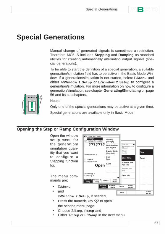
67
Special Generations
Manual change of generated signals is sometimes a restriction.Therefore MC5-IS includes Stepping and Ramping as standardutilities for creating automatically alternating output signals (spe-cial generations).
To be able to start the definition of a special generation, a suitablegeneration/simulation field has to be active in the Basic Mode Win-dow. If a generation/simulation is not started, select D/Menu andeither A/Window 1 Setup or B/Window 2 Setup to configure ageneration/simulation. For more information on how to configure ageneration/simulation, see chapter Generating/Simulating on page56 and its subchapters.
Notes.
Only one of the special generations may be active at a given time.
Special generations are available only in Basic Mode.
Opening the Step or Ramp Configuration WindowOpen the windowsetup menu forthe generation/simulation quan-tity that you wantto configure aStepping functionfor.
The menu com-mands are:
• D/Menu• and
B/Window 2 Setup, if needed,• Press the numeric key to open
the second menu page• Choose 3/Step, Ramp and• Either 1/Step or 2/Ramp in the next menu.
� � � � $ � � � � � � � � � � � �
� � � ' � � � � & � � ( � � � � � � �
� � � � � � � ) � � � � �
� �*7 7 7 7 7 7 7
8 . � � � � �
� � � � � + , � � �
� � � � � � � � � 7 � ' " " " " " " "
� � � � � * � � � � � �
* + � � � � , � '� � � � � � � , � '
" " " " " " "" " " " " " "
� � � � $ � � � � � � � � � � � �
� � � ' � � � � & � � ( � � � � � � �
� � � � � � � ) � � � � �
� �*7 7 7 7 7 7 7
8 . � � � � �
� � � � � + , � � �
� � � � � � � � � 7 � ' " " " " " " "
� � � � � * � � � � � �
* + � � � � , � '� � � � � � � , � '
" " " " " " "" " " " " " "
� � � � $ � � � � � � � � � � � �
� � � ' � � � � & � � ( � � � � � � �
� � � � � � � ) � � � � �
� �*7 7 7 7 7 7 7
8 . � � � � �
� � � � � + , � � �
� � � � � � � � � 7 � ' " " " " " " "
� � � � � * � � � � � �
* + � � � � , � '� � � � � � � , � '
" " " " " " "" " " " " " "
9 � � � � � �: * � � � � � � ;
0 � � � � � � 2 ! � � �: & 1 � * 4 � � � 5 ;
( � �: � ) ;
< ) - 1
+ � � � .� � � � , � �
� & ' (" � � � �
+ � � � .� � � � , � � 8 � � � � �
= � . � � � � � � � �: & � � � � ( � � ;
) � � � �: 3 3 4 3 3 5 ;
0 � � � � � � � � � � �! � � � � � � > �
& ? � � � � � � > �
+ � � � .� � � � , � �
� & ' (" � � � �
+ � � � .� � � � , � � 8 � � � � �
+ . � � � � �� � � � � � � � � � � �: ' � � � ;
�+ � � . @ � - � � .
+ � � � � � � ! � � � �� � > �
� & ' (" � � � �
�+ � � .
�- � � .
� � � A
Special Generations
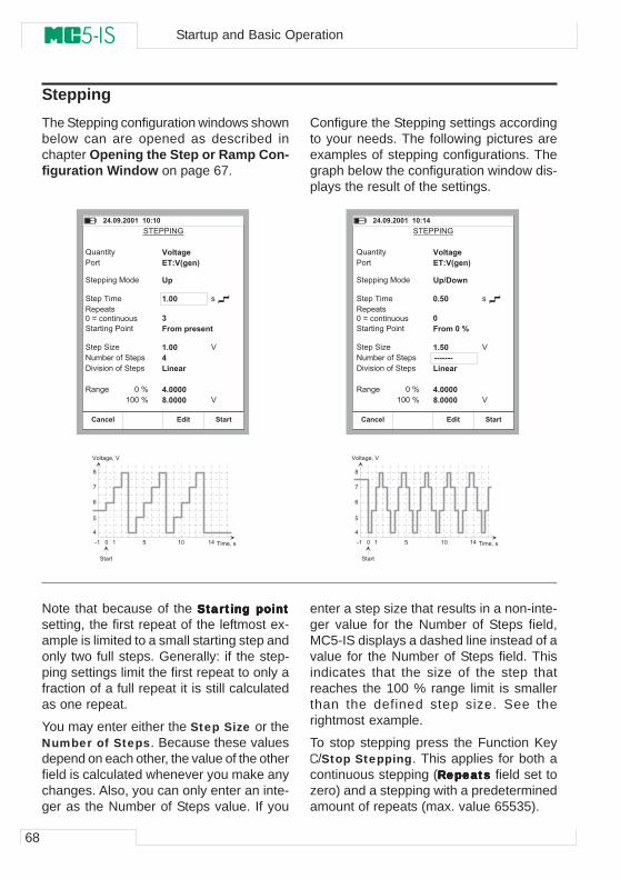
68
Startup and Basic Operation
SteppingConfigure the Stepping settings accordingto your needs. The following pictures areexamples of stepping configurations. Thegraph below the configuration window dis-plays the result of the settings.
Note that because of the StarStarStarStarStarting pointting pointting pointting pointting pointsetting, the first repeat of the leftmost ex-ample is limited to a small starting step andonly two full steps. Generally: if the step-ping settings limit the first repeat to only afraction of a full repeat it is still calculatedas one repeat.
You may enter either the Step Size or theNumber of Steps. Because these valuesdepend on each other, the value of the otherfield is calculated whenever you make anychanges. Also, you can only enter an inte-ger as the Number of Steps value. If you
enter a step size that results in a non-inte-ger value for the Number of Steps field,MC5-IS displays a dashed line instead of avalue for the Number of Steps field. Thisindicates that the size of the step thatreaches the 100 % range limit is smallerthan the defined step size. See therightmost example.
To stop stepping press the Function KeyC/Stop Stepping. This applies for both acontinuous stepping (RRRRReeeeepeapeapeapeapeatststststs field set tozero) and a stepping with a predeterminedamount of repeats (max. value 65535).
The Stepping configuration windows shownbelow can are opened as described inchapter Opening the Step or Ramp Con-figuration Window on page 67.
� $ � � / � � � � � � � � � � �
+ � � .- � � . � �
0 � � �
� � � � � � (
2 � � � � 3
� � � �
� � � + + � & � � � � �
� � � + � � � � �
- � + � � � �
� � � � � � & � � � � �
� � � + � � � : �
� � � � � � � 4 � � � � + �
6 � � � � � � � � 4 � � � � + �
- � & �
* � � � � � �& 1 * 4 � � � 5
( .
� � � �
0 � � � � . � � � � � �
� � � �$B � � � �
$ � � � � �� � � � � �
�
'
'
� ;
� � ;
+ � � � �" � � � � �
� < � � � � � � �
& � �
� � � � � � (
2 � � � � 3
� � � �
� � � + + � & � � � � �
� � � + � � � � �
- � + � � � �
� � � � � � & � � � � �
� � � + � � � : �
� � � � � � � 4 � � � � + �
6 � � � � � � � � 4 � � � � + �
- � & �
* � � � � � �& 1 * 4 � � � 5
( . 2 = � , �
� � � �
�0 � � � � � � C
� � � �3 3 3 3 3 3 3B � � � �
$ � � � � �� � � � � �
�
'
'
� ;
� � ;
� $ � � / � � � � � � � � � � $
� < � � � � � � �
+ � � .- � � . � �
0 � � � + � � � �" � � � � � & � �
%
=
#
>
$
' � � � � & � 7 � '
� � � � 7 � �� " � = � � %
� � � � �
%
=
#
>
$
' � � � � & � 7 � '
� � � � 7 � �� " � = � � %
� � � � �
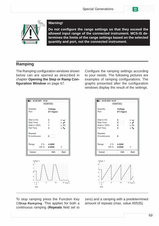
69
Warning!
Do not configure the range settings so that they exceed theallowed input range of the connected instrument. MC5-IS de-termines the limits of the range settings based on the selectedquantity and port, not the connected instrument.
RampingThe Ramping configuration windows shownbelow can are opened as described inchapter Opening the Step or Ramp Con-figuration Window on page 67.
Configure the ramping settings accordingto your needs. The following pictures areexamples of ramping configurations. Thegraphs presented after the configurationwindows display the result of the settings.
zero) and a ramping with a predeterminedamount of repeats (max. value 65535).
To stop ramping press the Function KeyC/Stop Ramping. This applies for both acontinuous ramping (Repeats field set to
- . � � � � (
� $ � � / � � � � � � � � � � �
2 � � � � 3
� � � �
- � � � � � � � �
9 � � � � � � � ;
/ � � � � � � � �
- � + � � � �
< � � � � � �
- � & �
* � � � � � �& 1 * 4 � � � 5
���
�
$ � � � � �� � � � � �
�
'
� ;
� � ;
�9 � � � � � � ; �
�
�
+ � � .- � � . � �
0 � � � + � � � �" � � � � � & � �
� $ � � / � � � � � � � � � �
* � � � � � �& 1 * 4 � � � 5
���
�
$ � � � � �� � � � � �
�
'
� ;
� � ;
� �
�
�
- . � � � � (
2 � � � � 3
� � � �
- � � � � � � � �
9 � � � � � � � ;
/ � � � � � � � �
- � + � � � �
< � � � � � �
- � & �
9 � � � � � � ;
+ � � .- � � . � �
0 � � � + � � � �" � � � � � & � �
' � � � � & � 7 � '
� � � � 7 � �� " � = � � %
� � � � �
%
=
#
>
$
' � � � � & � 7 � '
� � � � 7 � �
%
=
#
>
$
� " � = � � %
� � � � �
Special Generations
70
Startup and Basic Operation
Note.
MC5-IS actually makes the ramp in small steps. The steps are assmall as possible, slower ramps use smaller steps.
Warning!
Do not configure the range settings so that they exceed theallowed input range of the connected instrument. MC5-IS de-termines the limits of the range settings based on the selectedquantity and port, not the connected instrument.
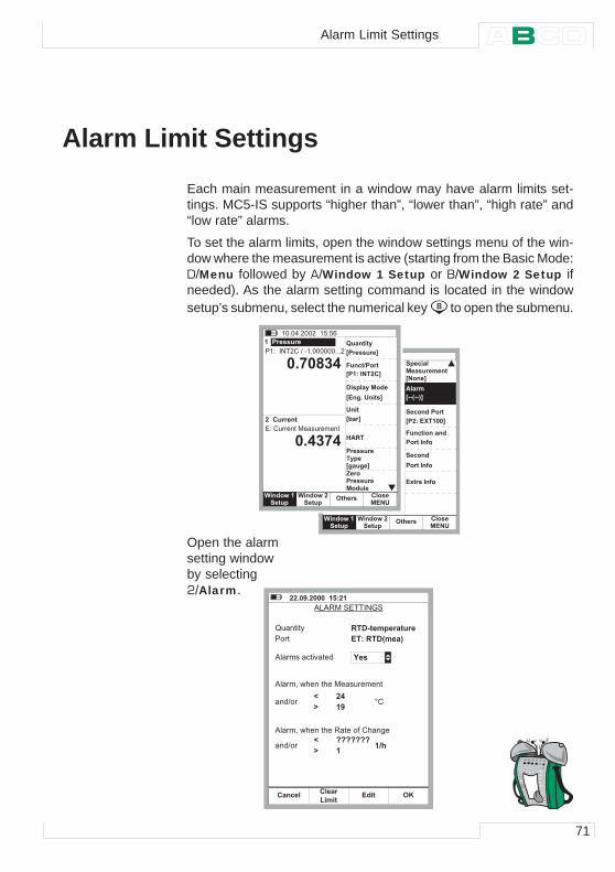
71
Alarm Limit Settings
Each main measurement in a window may have alarm limits set-tings. MC5-IS supports “higher than”, “lower than”, “high rate” and“low rate” alarms.
To set the alarm limits, open the window settings menu of the win-dow where the measurement is active (starting from the Basic Mode:D/Menu followed by A/Window 1 Setup or B/Window 2 Setup ifneeded). As the alarm setting command is located in the windowsetup’s submenu, select the numerical key to open the submenu.
Open the alarmsetting windowby selecting2/Alarm.
� # � �4 � � � � � 5
) � � � � � D
� � � # � �
+ . � � � �� � � � � � � � � � �: ' � � � ;
: 3 3 4 3 3 5 ;
0 � � � � � � � � � � �
! � � � � � � > �
) � � � �
+ � � � � �
& ? � � � � � � > �
! � � � � � � > �
" � � � �� & ' (� � � �
8 � � � � �� � � � , � � � � � � , � �+ � � � . + � � � .
+ � � � � � � ! � � � �
: ! � � & E 1 � � � ;
" � � � �� & ' (� � � �
8 � � � � �
� � % � � $ � # � �4 � � � � � 5
) � � � � � D
� � � � � � � � � � � ! � " � � � � � � � � � �
� � �
� � $ % $
� � � " � � � � � �
# � �
! � � � � � � �
� � � � � � � � � � � � � � � � �
9 � � � � � �
: ! � � � � � � � ;
: ! � � � ' 1 � " ;
: & � � � � ( � � � ;
( � �
: # � � ;
0 � � � � 2 ! � � �
= � . � � � � � � � �
� � % � � � � � � = � = # �
� �
< ) - 1
! � � � � � � �1 � . �: � � � � � ;F � � � �! � � � � � � �� � � � � �
� � � � , � � � � � � , � �+ � � � . + � � � .
� � � � / � � � � � � � � � � � �
. 5 . - � � � � � � � ( �
2 � � � � 3
� � � �
. � � � � � � � � � � � � � � �
. � � � � 7 � � ) � � � ) � � � � � � � � � � �
� � ! � �
- 1 = 3 � � � . � � � � � � �& 1 � - 1 = 4 � � � 5
� $� /
DG
8 �
. � � � � 7 � � ) � � � ) � � - � � � � � 4 � � ) � & �
� � ! � �7 7 7 7 7 7 7�
DG
� 2 �
H � �
" � � � � �B � �" � � � � 8 I& � �
Alarm Limit Settings
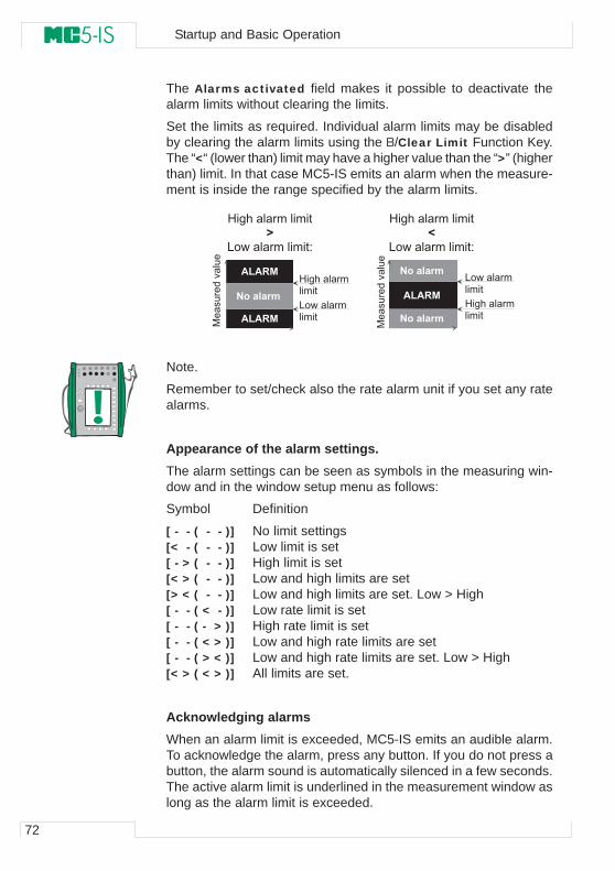
72
Startup and Basic Operation
The Alarms activated field makes it possible to deactivate thealarm limits without clearing the limits.
Set the limits as required. Individual alarm limits may be disabledby clearing the alarm limits using the B/Clear Limit Function Key.The “<“ (lower than) limit may have a higher value than the “>” (higherthan) limit. In that case MC5-IS emits an alarm when the measure-ment is inside the range specified by the alarm limits.
Note.
Remember to set/check also the rate alarm unit if you set any ratealarms.
Appearance of the alarm settings.The alarm settings can be seen as symbols in the measuring win-dow and in the window setup menu as follows:
Symbol Definition
[ - - ( - - )] No limit settings[< - ( - - )] Low limit is set[ - > ( - - )] High limit is set[< > ( - - )] Low and high limits are set[> < ( - - )] Low and high limits are set. Low > High[ - - ( < - )] Low rate limit is set[ - - ( - > )] High rate limit is set[ - - ( < > )] Low and high rate limits are set[ - - ( > < )] Low and high rate limits are set. Low > High[< > ( < > )] All limits are set.
Acknowledging alarmsWhen an alarm limit is exceeded, MC5-IS emits an audible alarm.To acknowledge the alarm, press any button. If you do not press abutton, the alarm sound is automatically silenced in a few seconds.The active alarm limit is underlined in the measurement window aslong as the alarm limit is exceeded.
0 � & ) � � � � � � � � � � � � �G �
5 � � � � � � � � � � � � � � �
0 � & ) � � � � � � � � � � � � �D �
5 � � � � � � � � � � � � � � �
) B ) - �
) B ) - �
' � � � � � � � �
' � � � � � � � �
' � � � � � � � �
5 � � � � � � � � �� � � � �
0 � & ) � � � � � � �� � � � �
5 � � � � � � � � �� � � � �
0 � & ) � � � � � � �� � � � � ) B ) - � �
������������
������������

Advanced Operationand Configurations
Things discussed in Part C:
• How to configure MC5-IS to suityour requirements.
• Advanced Utilities available in Ba-sic Mode.
• Additional information: Useful dur-ing pressure measurement, ther-mocouple measurement/simula-tion and resistance/RTD measure-ment/simulation.
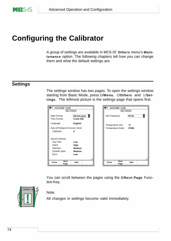
74
Advanced Operation and Configuration
Configuring the Calibrator
A group of settings are available in MC5-IS’ Others menu’s Main-tenance option. The following chapters tell how you can changethem and what the default settings are.
SettingsThe settings window has two pages. To open the settings windowstarting from Basic Mode, press D/Menu, C/Others and 1/Set-tings. The leftmost picture is the settings page that opens first.
You can scroll between the pages using the B/Next Page Func-tion Key.
Note.
All changes in settings become valid immediately.
13.03.2002 12:53 SETTINGS
Date FormatTime Format
Language
Auto-off Delays (0=never) [min]Calibrator
Sound VolumesKey ClickAlarmAttentionOutside SpanError
h:mm 24h
English
0
LowHighMediumMediumLow
Close
dd.mm.yyyy
PageNext Edit
13.03.2002 12:59
Net Frequency 50 Hz
Temperature UnitTemperature Scale
°CITS90
SETTINGS
ClosePageNext Edit
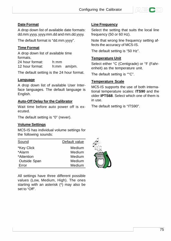
75
Date FormatA drop down list of available date formats:dd.mm.yyyy, yyyy.mm.dd and mm.dd.yyyy.
The default format is “dd.mm.yyyy”.
Time FormatA drop down list of available timeformats.24 hour format: h:mm12 hour format: h:mm am/pm.
The default setting is the 24 hour format.
LanguageA drop down list of available User Inter-face languages. The default language isEnglish.
Auto-Off Delay for the CalibratorWait time before auto power off is ex-ecuted.
The default setting is “0” (never).
Volume SettingsMC5-IS has individual volume settings forthe following sounds:
Sound Default value
*Key Click Medium*Alarm Medium*Attention Medium Outside Span Medium Error Medium
All settings have three different possiblevalues (Low, Medium, High). The onesstarting with an asterisk (*) may also beset to “Off”.
Line FrequencySelect the setting that suits the local linefrequency (50 or 60 Hz).
Note that wrong line frequency setting af-fects the accuracy of MC5-IS.
The default setting is “50 Hz”.
Temperature UnitSelect either °C (Centigrade) or °F (Fahr-enheit) as the temperature unit.
The default setting is “°C”.
Temperature ScaleMC5-IS supports the use of both interna-tional temperature scales: ITS90 and theolder IPTS68. Select which one of them isin use.
The default setting is “ITS90”.
Configuring the Calibrator
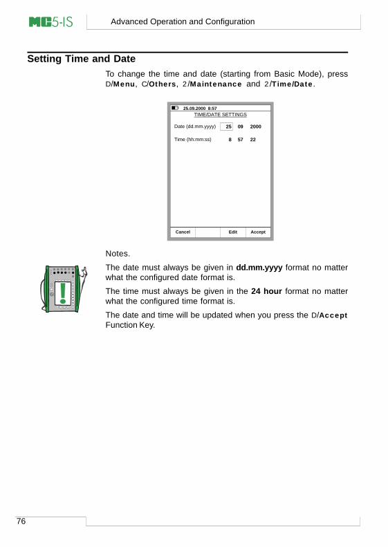
76
Advanced Operation and Configuration
Setting Time and DateTo change the time and date (starting from Basic Mode), pressD/Menu, C/Others, 2/Maintenance and 2/Time/Date.
Notes.
The date must always be given in dd.mm.yyyy format no matterwhat the configured date format is.
The time must always be given in the 24 hour format no matterwhat the configured time format is.
The date and time will be updated when you press the D/AcceptFunction Key.
25.09.2000 8:57 TIME/DATE SETTINGS
Date (dd.mm.yyyy)
Time (hh:mm:ss) 8
25
57
09
22
2000
Cancel AcceptEdit
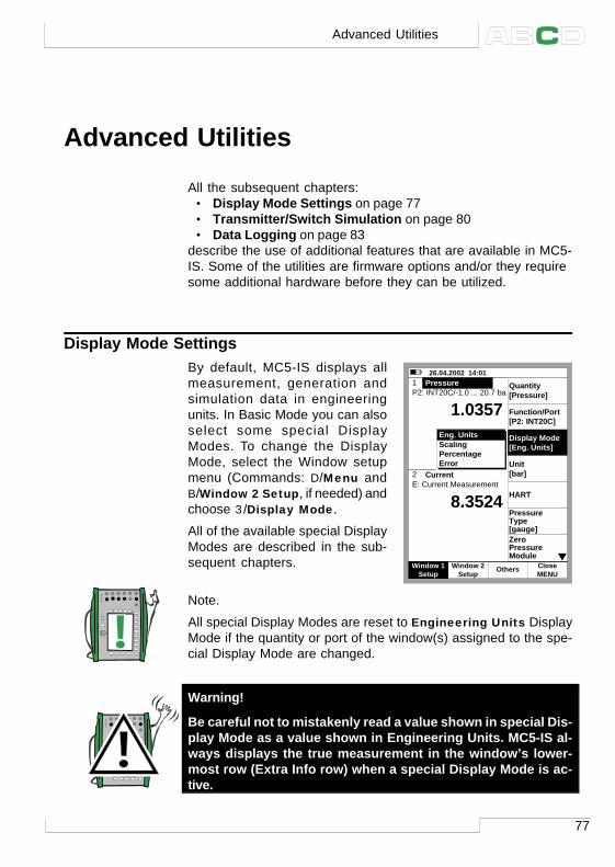
77
Advanced Utilities
All the subsequent chapters:• Display Mode Settings on page 77• Transmitter/Switch Simulation on page 80• Data Logging on page 83
describe the use of additional features that are available in MC5-IS. Some of the utilities are firmware options and/or they requiresome additional hardware before they can be utilized.
Display Mode SettingsBy default, MC5-IS displays allmeasurement, generation andsimulation data in engineeringunits. In Basic Mode you can alsoselect some special DisplayModes. To change the DisplayMode, select the Window setupmenu (Commands: D/Menu andB/Window 2 Setup, if needed) andchoose 3/Display Mode.
All of the available special DisplayModes are described in the sub-sequent chapters.
Note.
All special Display Modes are reset to Engineering Units DisplayMode if the quantity or port of the window(s) assigned to the spe-cial Display Mode are changed.
Warning!
Be careful not to mistakenly read a value shown in special Dis-play Mode as a value shown in Engineering Units. MC5-IS al-ways displays the true measurement in the window’s lower-most row (Extra Info row) when a special Display Mode is ac-tive.
26.04.2002 14:01
P2: INT20C/-1.0 ... 20.7 bar g
E: Current Measurement
gauge bar1.0357
8.3524 mA
2 Current
1 Pressure Quantity[Pressure]
Function/Port[P2: INT20C]
Unit[bar]
HART
SetupWindow 2
MENUClose
SetupWindow 1 Others
Display Mode[Eng. Units]
Pressure Type[gauge]Zero PressureModule
Eng. UnitsScalingPercentageError
Advanced Utilities
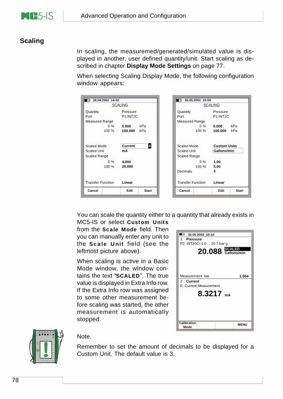
78
Advanced Operation and Configuration
ScalingIn scaling, the measuremed/generated/simulated value is dis-played in another, user defined quantity/unit. Start scaling as de-scribed in chapter Display Mode Settings on page 77.
When selecting Scaling Display Mode, the following configurationwindow appears:
SCALING26.04.2002 14:02
QuantityPort
PressureP1:INT2C
Measured Range
kPa
StopRamping
Field StartCancel Edit
0 %100 %
kPa0.000100.000
Scaled ModeScaled Unit mAScaled Range
0 %100 %
4.00020.000
Transfer Function Linear
Current
SCALING30.05.2002 10:09
QuantityPort
PressureP1:INT2C
Measured Range
kPa
StopRamping
Field StartCancel Edit
0 %100 %
kPa0.000100.000
Scaled Mode Custom UnitsScaled UnitScaled Range
0 %100 %
1.005.00
Transfer Function Linear
Gallons/min
Decimals 3
You can scale the quantity either to a quantity that already exists inMC5-IS or select Custom Unitsfrom the Scale Mode field. Thenyou can manually enter any unit tothe Scale Unit field (see theleftmost picture above).
When scaling is active in a BasicMode window, the window con-tains the text “SCALED”. The truevalue is displayed in Extra Info row.If the Extra Info row was assignedto some other measurement be-fore scaling was started, the othermeasurement is automaticallystopped.
Note.
Remember to set the amount of decimals to be displayed for aCustom Unit. The default value is 3.
30.05.2002 10:10
P2: INT20C/-1.0 ... 20.7 bar g
E: Current Measurement
Gallons/min20.088
8.3217 mA
2 Current
1 Pressure
Measurement bar 1.004
ModeCalibration MENU
SCALED
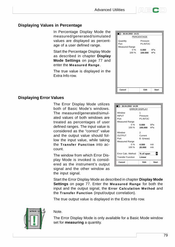
79
Displaying Values in PercentageIn Percentage Display Mode themeasured/generated/simulatedvalues are displayed as percent-age of a user defined range.
Start the Percentage Display Modeas described in chapter DisplayMode Settings on page 77 andenter the Measured Range.
The true value is displayed in theExtra Info row.
Displaying Error ValuesThe Error Display Mode utilizesboth of Basic Mode’s windows.The measured/generated/simul-ated values of both windows aretreated as percentages of userdefined ranges. The input value isconsidered as the “correct” valueand the output value should fol-low the input value, while takingthe Transfer Function into ac-count.
The window from which Error Dis-play Mode is invoked is consid-ered as the instrument’s outputsignal and the other window asthe input signal.
Start the Error Display Mode as described in chapter Display ModeSettings on page 77. Enter the Measured Range for both theinput and the output signal, the Error Calculation Method andthe Transfer Function (input/output correlation).
The true output value is displayed in the Extra Info row.
Note.
The Error Display Mode is only available for a Basic Mode windowset for measuring a quantity.
PERCENTAGE26.04.2002 14:21
QuantityPort
PressureP1:INT2C
Measured Range
kPa
StopRamping
Field StartCancel Edit
0 %100 %
kPa0.000100.000
ERROR DISPLAY26.04.2002 14:29
INPUTPort
PressureP1:INT2C
Measured Range
kPa
StopRamping
Field StartCancel Edit
0 %100 %
kPa0.000100.000
Transfer Function LinearError Calc. Method % of span
OUTPUTPort
CurrentE: I(meas)
Measured Range
mA0 %
100 %mA4.000
20.000
Window
Window
1
2
Advanced Utilities
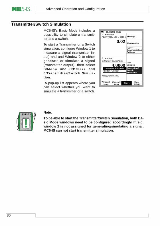
80
Advanced Operation and Configuration
Transmitter/Switch SimulationMC5-IS’s Basic Mode includes apossibility to simulate a transmit-ter and a switch.
To start a Transmitter or a Switchsimulation, configure Window 1 tomeasure a signal (transmitter in-put) and and Window 2 to eithergenerate or simulate a signal(transmitter output), then selectD/Menu and C /Others and6/Transmitter/Switch Simula-tion.
A pop-up list appears where youcan select whether you want tosimulate a transmitter or a switch.
Note.To be able to start the Transmitter/Switch Simulation, both Ba-sic Mode windows need to be configured accordingly. If, e.g.window 2 is not assigned for generating/simulating a signal,MC5-IS can not start transmitter simulation.
18.04.2002 15:15
P2: INT20C/-100 ... 2068 kPa g
E: Current Source/Sink
gauge kPa0.02
mA
2 Current
1 Pressure
End MENU
Measurement mA 4.0000
Pause
4.0000
SetupWindow 2
MENUClose
SetupWindow 1 Others
Data Logging
Settings
Maintenance
HART
Settings
Transmitter/SwitchSimulation
Communication
Transmitter FunctionSwitch Function
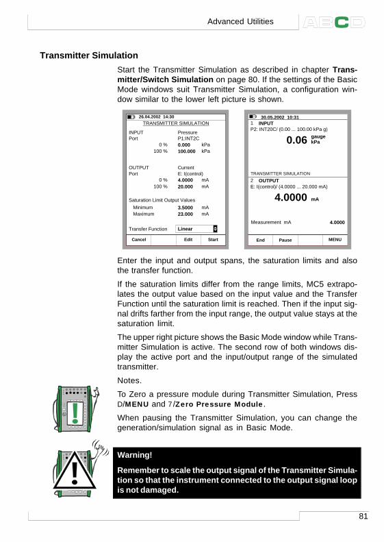
81
Transmitter SimulationStart the Transmitter Simulation as described in chapter Trans-mitter/Switch Simulation on page 80. If the settings of the BasicMode windows suit Transmitter Simulation, a configuration win-dow similar to the lower left picture is shown.
TRANSMITTER SIMULATION26.04.2002 14:30
INPUTPort
PressureP1:INT2C
kPa
StopRamping
Field StartCancel Edit
100 %kPa0.000
100.000
Transfer Function
0 %
OUTPUTPort
CurrentE: I(control)
mA100 %mA4.0000
20.0000 %
Saturation Limit Output Values
mAMaximummA3.5000
23.000Minimum
Linear
30.05.2002 10:31
P2: INT20C/ (0.00 ... 100.00 kPa g)
E: I(control)/ (4.0000 ... 20.000 mA)
gauge kPa0.06
4.0000 mA
2 OUTPUT
1 INPUT
End MENU
Measurement mA 4.0000
Pause
TRANSMITTER SIMULATION
Enter the input and output spans, the saturation limits and alsothe transfer function.
If the saturation limits differ from the range limits, MC5 extrapo-lates the output value based on the input value and the TransferFunction until the saturation limit is reached. Then if the input sig-nal drifts farther from the input range, the output value stays at thesaturation limit.
The upper right picture shows the Basic Mode window while Trans-mitter Simulation is active. The second row of both windows dis-play the active port and the input/output range of the simulatedtransmitter.
Notes.
To Zero a pressure module during Transmitter Simulation, PressD/MENU and 7/Zero Pressure Module.
When pausing the Transmitter Simulation, you can change thegeneration/simulation signal as in Basic Mode.
Warning!
Remember to scale the output signal of the Transmitter Simula-tion so that the instrument connected to the output signal loopis not damaged.
Advanced Utilities
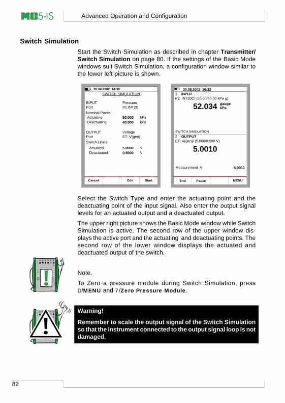
82
Advanced Operation and Configuration
Switch SimulationStart the Switch Simulation as described in chapter Transmitter/Switch Simulation on page 80. If the settings of the Basic Modewindows suit Switch Simulation, a configuration window similar tothe lower left picture is shown.
SWITCH SIMULATION26.04.2002 14:38
StopRamping
Field StartCancel Edit
INPUTPort
PressureP1:INT2C
kPakPa50.000
40.000
OUTPUTPort
VoltageET: V(gen)
VV5.0000
0.5000DeactuatedActuated
DeactuatingActuating
Nominal Points
Switch Limits
30.05.2002 10:32
P2: INT20C/ (50.00/40.00 kPa g)
ET: V(gen)/ (5.000/0.500 V)
gauge kPa52.034
5.0010
2 OUTPUT
1 INPUT
End MENU
Measurement V 5.0011
Pause
SWITCH SIMULATION
Select the Switch Type and enter the actuating point and thedeactuating point of the input signal. Also enter the output signallevels for an actuated output and a deactuated output.
The upper right picture shows the Basic Mode window while SwitchSimulation is active. The second row of the upper window dis-plays the active port and the actuating and deactuating points. Thesecond row of the lower window displays the actuated anddeactuated output of the switch.
Note.
To Zero a pressure module during Switch Simulation, pressD/MENU and 7/Zero Pressure Module.
Warning!
Remember to scale the output signal of the Switch Simulationso that the instrument connected to the output signal loop is notdamaged.
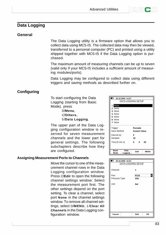
83
Data Logging
GeneralThe Data Logging utility is a firmware option that allows you tocollect data using MC5-IS. The collected data may then be viewed,transferred to a personal computer (PC) and printed using a utilityshipped together with MC5-IS if the Data Logging option is pur-chased.
The maximum amount of measuring channels can be up to seven(valid only if your MC5-IS includes a sufficient amount of measur-ing modules/ports).
Data Logging may be configured to collect data using differenttriggers and saving methods as described further on.
ConfiguringTo start configuring the DataLogging (starting from BasicMode), press
D/Menu,C/Others,5/Data Logging.
The upper part of the Data Log-ging configuration window is re-served for seven measurementchannels and the lower part forgeneral settings. The followingsubchapters describe how theyare configured.
Assigning Measurement Ports to ChannelsMove the cursor to one of the meas-urement channel rows in the DataLogging configuration window.Press C/Edit to open the followingchannel settings window: Selectthe measurement port first. Theother settings depend on the portsetting. To clear a channel, selectport None in the channel settingswindow. To remove all channel set-tings, select D/MENU, 1/Clear AllChannels in the Data Logging con-figuration window.
20.10.2000 14:57 DATA LOGGING SETUP
1
Trigger
None2 None3 None4 None5 None6 None7 None
Save Method
Interval [s]Samples
Time [h min s]
PeriodicInstant Value
210
0
ModeBasic
LoggingData Edit MENU
0 20
20.10.2000 15:01 DATA LOGGING SETUP
Channel
PortPressure Type
Unit
1
Abs
bar
P3:B
Cancel OKEdit
Advanced Utilities
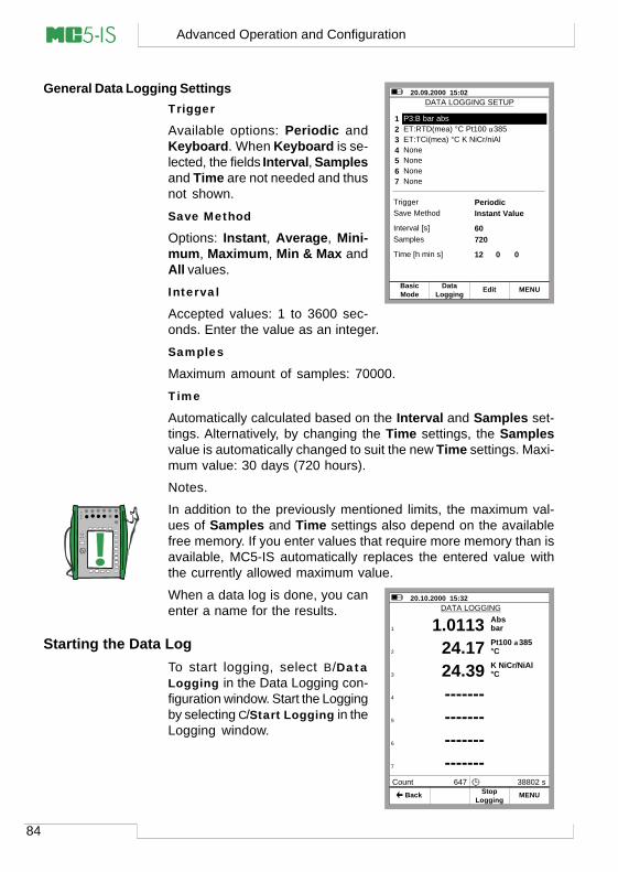
84
Advanced Operation and Configuration
General Data Logging SettingsTrigger
Available options: Periodic andKeyboard. When Keyboard is se-lected, the fields Interval, Samplesand Time are not needed and thusnot shown.
Save Method
Options: Instant, Average, Mini-mum, Maximum, Min & Max andAll values.
Interval
Accepted values: 1 to 3600 sec-onds. Enter the value as an integer.
Samples
Maximum amount of samples: 70000.
Time
Automatically calculated based on the Interval and Samples set-tings. Alternatively, by changing the Time settings, the Samplesvalue is automatically changed to suit the new Time settings. Maxi-mum value: 30 days (720 hours).
Notes.
In addition to the previously mentioned limits, the maximum val-ues of Samples and Time settings also depend on the availablefree memory. If you enter values that require more memory than isavailable, MC5-IS automatically replaces the entered value withthe currently allowed maximum value.
When a data log is done, you canenter a name for the results.
Starting the Data LogTo start logging, select B/DataLogging in the Data Logging con-figuration window. Start the Loggingby selecting C/Start Logging in theLogging window.
20.09.2000 15:02 DATA LOGGING SETUP
1
Trigger
2 ET:RTD(mea) °C Pt100 α3853 ET:TCi(mea) °C K NiCr/niAl4 None5 None6 None7 None
Save Method
Interval [s]Samples
Time [h min s]
PeriodicInstant Value
60720
12
ModeBasic
LoggingData Edit MENU
P3:B bar abs
0 0
Absbar1.0113
20.10.2000 15:32 DATA LOGGING
Pt100 α385°C24.17K NiCr/NiAl°C24.39Posit. kanttikHz-------Posit. kanttikHz-------Posit. kanttikHz-------Posit. kanttikHz-------
1
2
3
4
5
6
7
Count 647 38802 s
LoggingStop MENU Back
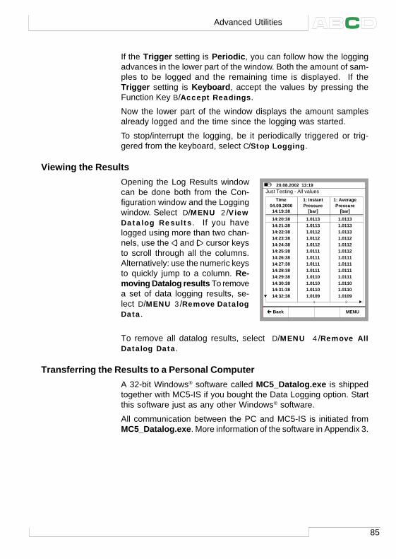
85
If the Trigger setting is Periodic, you can follow how the loggingadvances in the lower part of the window. Both the amount of sam-ples to be logged and the remaining time is displayed. If theTrigger setting is Keyboard, accept the values by pressing theFunction Key B/Accept Readings.
Now the lower part of the window displays the amount samplesalready logged and the time since the logging was started.
To stop/interrupt the logging, be it periodically triggered or trig-gered from the keyboard, select C/Stop Logging.
Viewing the ResultsOpening the Log Results windowcan be done both from the Con-figuration window and the Loggingwindow. Select D/MENU 2/ViewDatalog Results. If you havelogged using more than two chan-nels, use the and cursor keysto scroll through all the columns.Alternatively: use the numeric keysto quickly jump to a column. Re-moving Datalog results To removea set of data logging results, se-lect D/MENU 3/Remove DatalogData.
To remove all datalog results, select D/MENU 4/Remove AllDatalog Data.
Transferring the Results to a Personal ComputerA 32-bit Windows® software called MC5_Datalog.exe is shippedtogether with MC5-IS if you bought the Data Logging option. Startthis software just as any other Windows® software.
All communication between the PC and MC5-IS is initiated fromMC5_Datalog.exe. More information of the software in Appendix 3.
20.08.2002 13:19
Back MENU
Just Testing - All valuesTime
14:19:38
14:20:3814:21:3814:22:3814:23:3814:24:3814:25:3814:26:3814:27:3814:28:3814:29:3814:30:3814:31:3814:32:38
1: Instant
[bar]
1.01131.01131.01121.01121.01121.01111.01111.01111.01111.01101.01101.01101.0109
1: Average
[bar]
1.01131.01131.01131.01121.01121.01121.01111.01111.01111.01111.01101.01101.0109
1 2
04.09.2000 Pressure Pressure
Advanced Utilities
86
Advanced Operation and Configuration
Additional Information
Most of the measurements, generations and simulations pre-sented in this manual are straight forward: Just make the requiredwindow settings and connect the instrument under test in the ac-tive terminals and that’s it!
Some cases require additional settings and things to check be-fore you can be certain that the measurement, generation or simu-lation works as expected. A typical example of this is temperaturemeasurement using a thermocouple. It is not enough to select thecorrect quantity and port in MC5-IS. The Sensor type and the Refer-ence Junction Mode has to be set accordingly, too. Wrong settingsgive erroneous results.
Whenever this additional information may be of use in a measure-ment, generation or simulation, text describing the function refersto one of the following chapters. An experienced user need notjump to read this supplemental text, but for a beginner we highlyrecommend it.
The main subjects described here are:
Things to Consider when Measuring Pressure on page 87,Thermocouple Measurement/Simulation, Connections andTroubleshooting on page 89,Resistance and RTD Measurement, Connections on page 93,Current Measurement Parallel to a Test Diode, Connections onpage 95 andParallel Functions in MC5-IS on page 96.
87
Things to Consider when Measuring Pressure
GeneralMC5-IS can measure pressure with its internal pressure modules,or with external pressure modules. If a barometric module ispresent, the measurement results of other modules can be showneither as absolute pressure or as gauge pressure.
Pressure TypeEvery pressure measurement is in fact a pressure difference mea-surement: a given pressure value is compared against a refer-ence pressure. In certain cases the reference pressure has aspecial meaning (like the atmospheric pressure) and the pres-sure measurements with reference to against these points aregiven a special name:
• Absolute pressure measurement uses vacuum as the ref-erence pressure.
• Barometric pressure (or atmospheric pressure) is the ab-solute pressure of the surrounding atmosphere. It is spe-cially titled because of its importance.
• Gauge pressure measurement uses the atmospheric pres-sure as the reference. Gauge pressure may be zero, negativeor positive. Most of MC5-IS’ pressure modules actually mea-sure gauge pressure although they may be used for measur-ing other pressure types too.
• Differential pressure measurement requires a special dif-ferential pressure module that has an input available for boththe reference pressure and the given pressure.
To be able to measure absolute pressure with MC5-IS’ gaugepressure modules, you need a barometric pressure module. Cer-tain high pressure modules may approximate absolute pressuremeasurement by adding an entered barometric pressure to themeasured gauge pressure.
MC5-IS may use two standard pressure modules to measure dif-ferential pressure: One module measures the reference pres-sure and another the given pressure. The pressure difference iscalculated by subtracting the reference pressure from the givenpressure. More of this in Part B, chapter Special Measurements.
Always ensure that the pressure type setting of your pressuremeasurement is what you intended it to be. The pressure typesetting is crucial for getting meaningful pressure measurementresults.
Additional Information
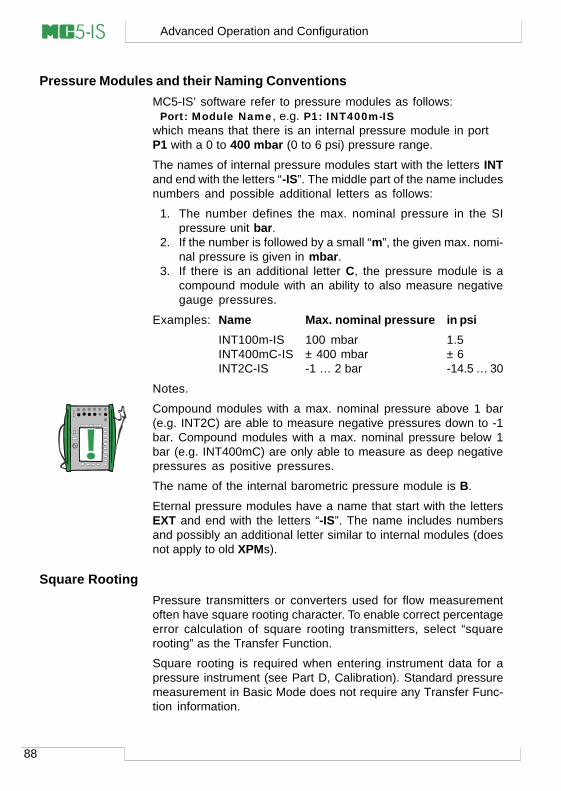
88
Advanced Operation and Configuration
Pressure Modules and their Naming ConventionsMC5-IS’ software refer to pressure modules as follows:
Port: Module Name, e.g. P1: INT400m-ISwhich means that there is an internal pressure module in portP1 with a 0 to 400 mbar (0 to 6 psi) pressure range.
The names of internal pressure modules start with the letters INTand end with the letters “-IS”. The middle part of the name includesnumbers and possible additional letters as follows:
1. The number defines the max. nominal pressure in the SIpressure unit bar.
2. If the number is followed by a small “m”, the given max. nomi-nal pressure is given in mbar.
3. If there is an additional letter C, the pressure module is acompound module with an ability to also measure negativegauge pressures.
Examples: Name Max. nominal pressure in psiINT100m-IS 100 mbar 1.5INT400mC-IS ± 400 mbar ± 6INT2C-IS -1 … 2 bar -14.5 … 30
Notes.
Compound modules with a max. nominal pressure above 1 bar(e.g. INT2C) are able to measure negative pressures down to -1bar. Compound modules with a max. nominal pressure below 1bar (e.g. INT400mC) are only able to measure as deep negativepressures as positive pressures.
The name of the internal barometric pressure module is B.
Eternal pressure modules have a name that start with the lettersEXT and end with the letters “-IS”. The name includes numbersand possibly an additional letter similar to internal modules (doesnot apply to old XPMs).
Square RootingPressure transmitters or converters used for flow measurementoften have square rooting character. To enable correct percentageerror calculation of square rooting transmitters, select “squarerooting” as the Transfer Function.
Square rooting is required when entering instrument data for apressure instrument (see Part D, Calibration). Standard pressuremeasurement in Basic Mode does not require any Transfer Func-tion information.
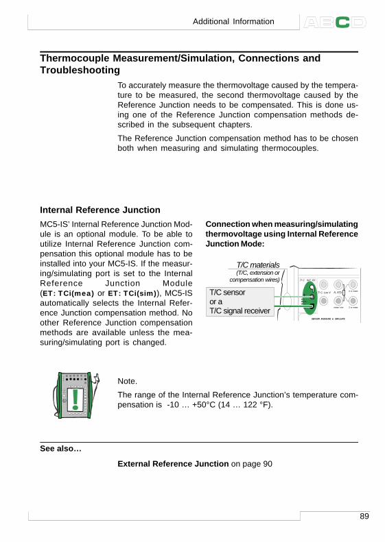
89
Thermocouple Measurement/Simulation, Connections andTroubleshooting
To accurately measure the thermovoltage caused by the tempera-ture to be measured, the second thermovoltage caused by theReference Junction needs to be compensated. This is done us-ing one of the Reference Junction compensation methods de-scribed in the subsequent chapters.
The Reference Junction compensation method has to be chosenboth when measuring and simulating thermocouples.
Internal Reference JunctionMC5-IS’ Internal Reference Junction Mod-ule is an optional module. To be able toutilize Internal Reference Junction com-pensation this optional module has to beinstalled into your MC5-IS. If the measur-ing/simulating port is set to the InternalReference Junction Module(ET: TCi(mea) or ET: TCi(sim)), MC5-ISautomatically selects the Internal Refer-ence Junction compensation method. Noother Reference Junction compensationmethods are available unless the mea-suring/simulating port is changed.
Connection when measuring/simulatingthermovoltage using Internal ReferenceJunction Mode:
Note.
The range of the Internal Reference Junction’s temperature com-pensation is -10 … +50°C (14 … 122 °F).
See also…
External Reference Junction on page 90
T/C, Low V R, RTD
T/C INT. RJ
SENSOR MEASURE & SIMULATE
T/C WIRES ONLY
4 w meas
3 w measmeas/sim
T/C sensor or a T/C signal receiver
T/C materials (T/C, extension or
compensation wires)
T/C WIRES ONLY
Additional Information
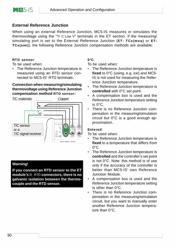
90
Advanced Operation and Configuration
External Reference JunctionWhen using an external Reference Junction, MC5-IS measures or simulates thethermovoltage using the “T/C Low V” terminals in the ET section. If the measuring/simulating port is set to the External Reference Junction (ET: TCx(mea) or ET:TCx(sim)), the following Reference Junction compensation methods are available:
0°C:To be used when:• The Reference Junction temperature is
fixed to 0°C (using, e.g. ice) and MC5-IS is not used for measuring the Refer-ence Junction temperature.
• The Reference Junction temperature iscontrolled with 0°C set point.
• A compensation box is used and theReference Junction temperature settingis 0°C.
• There is no Reference Junction com-pensation in the measuring/simulationcircuit but 0°C is a good enough ap-proximation.
Entered:To be used when:• The Reference Junction temperature is
fixed to a temperature that differs from0°C.
• The Reference Junction temperature iscontrolled and the controller’s set pointis not 0°C. Note: this method is of useonly if the accuracy of the controller isbetter than MC5-IS’ own ReferenceJunction Module.
• A compensation box is used and theReference Junction temperature settingis other than 0°C.
• There is no Reference Junction com-pensation in the measuring/simulationcircuit, but you want to manually enteranother Reference Junction tempera-ture than 0°C.
Warning!If you connect an RTD sensor to the ETmodule’s R, RTD connectors, there is nogalvanic isolation between the thermo-couple and the RTD sensor.
RTD sensor:To be used when:• The Reference Junction temperature is
measured using an RTD sensor con-nected to MC5-IS’ RTD terminals.
Connection when measuring/simulatingthermovoltage using Reference Junctioncompensation method RTD sensor:
T/C, Low V R, RTD
T/C INT. RJ
SENSOR MEASURE & SIMULATE
T/C WIRES ONLY
4 w meas
3 w measmeas/sim
T/C, Low V
T/C sensor or a T/C signal receiver
T/C materials Copper
Tref
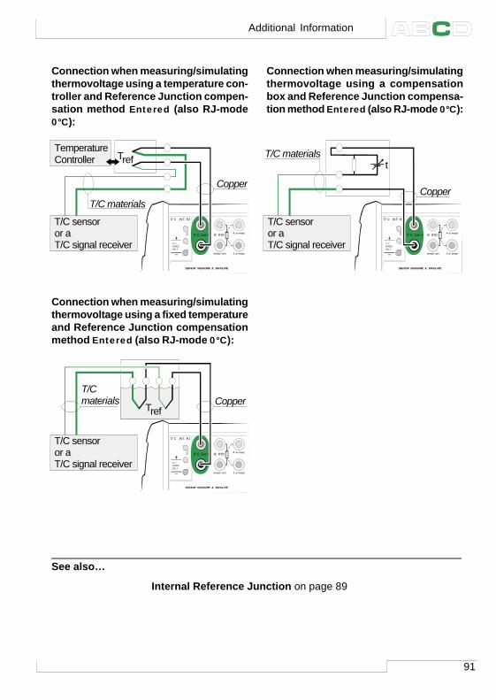
91
Connection when measuring/simulatingthermovoltage using a temperature con-troller and Reference Junction compen-sation method Entered (also RJ-mode0°C):
Connection when measuring/simulatingthermovoltage using a compensationbox and Reference Junction compensa-tion method Entered (also RJ-mode 0°C):
See also…
Internal Reference Junction on page 89
T/C, Low V R, RTD
T/C INT. RJ
SENSOR MEASURE & SIMULATE
T/C WIRES ONLY
4 w meas
3 w measmeas/sim
T/C, Low V
T/C materials CopperTref
T/C sensoror a T/C signal receiver
T/C, Low V R, RTD
T/C INT. RJ
SENSOR MEASURE & SIMULATE
T/C WIRES ONLY
4 w meas
3 w measmeas/sim
t
T/C sensoror a T/C signal receiver
T/C materials
Copper
T/C, Low V
Connection when measuring/simulatingthermovoltage using a fixed temperatureand Reference Junction compensationmethod Entered (also RJ-mode 0°C):
T/C, Low V R, RTD
T/C INT. RJ
SENSOR MEASURE & SIMULATE
T/C WIRES ONLY
4 w meas
3 w measmeas/sim
T/C, Low V
Copper
T/C sensoror a T/C signal receiver
Temperature Controller Tref
T/C materials
Additional Information
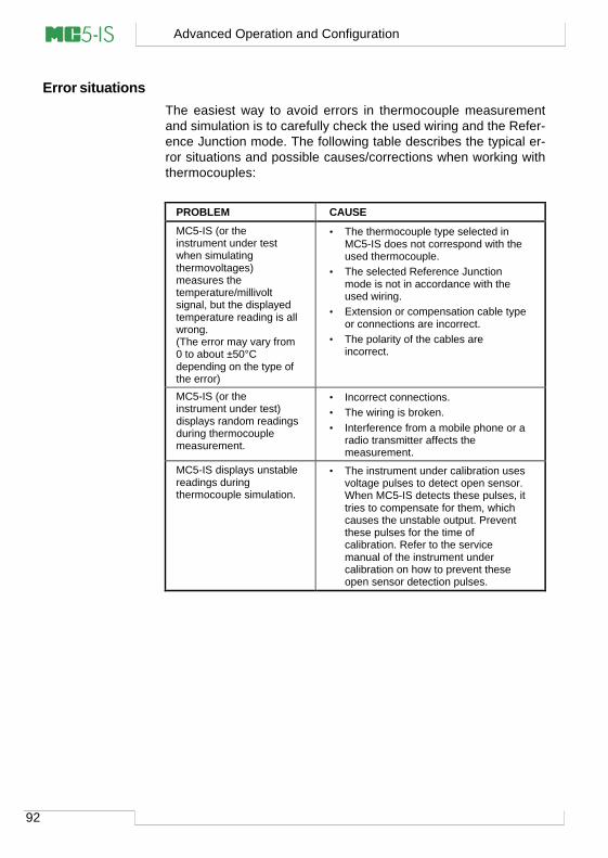
92
Advanced Operation and Configuration
Error situationsThe easiest way to avoid errors in thermocouple measurementand simulation is to carefully check the used wiring and the Refer-ence Junction mode. The following table describes the typical er-ror situations and possible causes/corrections when working withthermocouples:
PROBLEM CAUSE
MC5-IS (or theinstrument under testwhen simulatingthermovoltages)measures thetemperature/millivoltsignal, but the displayedtemperature reading is allwrong.(The error may vary from0 to about ±50°Cdepending on the type ofthe error)
• The thermocouple type selected inMC5-IS does not correspond with theused thermocouple.
• The selected Reference Junctionmode is not in accordance with theused wiring.
• Extension or compensation cable typeor connections are incorrect.
• The polarity of the cables areincorrect.
MC5-IS (or theinstrument under test)displays random readingsduring thermocouplemeasurement.
• Incorrect connections.• The wiring is broken.• Interference from a mobile phone or a
radio transmitter affects themeasurement.
MC5-IS displays unstablereadings duringthermocouple simulation.
• The instrument under calibration usesvoltage pulses to detect open sensor.When MC5-IS detects these pulses, ittries to compensate for them, whichcauses the unstable output. Preventthese pulses for the time ofcalibration. Refer to the servicemanual of the instrument undercalibration on how to prevent theseopen sensor detection pulses.
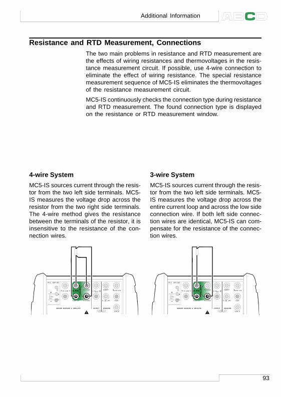
93
Resistance and RTD Measurement, ConnectionsThe two main problems in resistance and RTD measurement arethe effects of wiring resistances and thermovoltages in the resis-tance measurement circuit. If possible, use 4-wire connection toeliminate the effect of wiring resistance. The special resistancemeasurement sequence of MC5-IS eliminates the thermovoltagesof the resistance measurement circuit.
MC5-IS continuously checks the connection type during resistanceand RTD measurement. The found connection type is displayedon the resistance or RTD measurement window.
3-wire SystemMC5-IS sources current through the resis-tor from the two left side terminals. MC5-IS measures the voltage drop across theentire current loop and across the low sideconnection wire. If both left side connec-tion wires are identical, MC5-IS can com-pensate for the resistance of the connec-tion wires.
4-wire SystemMC5-IS sources current through the resis-tor from the two left side terminals. MC5-IS measures the voltage drop across theresistor from the two right side terminals.The 4-wire method gives the resistancebetween the terminals of the resistor, it isinsensitive to the resistance of the con-nection wires.
R, RTDT/C, Low V HART® Imeas/sink
V, ,
V, I , sink
Com
R, RTD
Low V
MEASUREOUTPUT
ET E
T/C INT. RJ
SENSOR MEASURE & SIMULATE
Uo: 16 V Io: 24 mA
Po: 145 mW
T/C WIRES ONLY
4 w meas
3 w measmeas/sim
R, RTDT/C, Low V HART® Imeas/sink
V, ,
V, I , sink
Com
R, RTD
Low V
MEASUREOUTPUT
ET E
T/C INT. RJ
SENSOR MEASURE & SIMULATE
Uo: 16 V Io: 24 mA
Po: 145 mW
T/C WIRES ONLY
4 w meas
3 w measmeas/sim
Additional Information
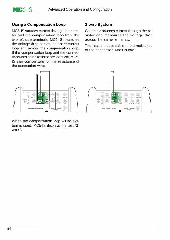
94
Advanced Operation and Configuration
Using a Compensation LoopMC5-IS sources current through the resis-tor and the compensation loop from thetwo left side terminals. MC5-IS measuresthe voltage drop across the entire currentloop and across the compensation loop.If the compensation loop and the connec-tion wires of the resistor are identical, MC5-IS can compensate for the resistance ofthe connection wires.
When the compensation loop wiring sys-tem is used, MC5-IS displays the text “3-wire”.
2-wire SystemCalibrator sources current through the re-sistor and measures the voltage dropacross the same terminals.
The result is acceptable, if the resistanceof the connection wires is low.
R, RTDT/C, Low V HART® Imeas/sink
V, ,
V, I , sink
Com
R, RTD
Low V
MEASUREOUTPUT
ET E
T/C INT. RJ
SENSOR MEASURE & SIMULATE
Uo: 16 V Io: 24 mA
Po: 145 mW
T/C WIRES ONLY
4 w meas
3 w measmeas/sim
R, RTDT/C, Low V HART® Imeas/sink
V, ,
V, I , sink
Com
R, RTD
Low V
MEASUREOUTPUT
ET E
T/C INT. RJ
SENSOR MEASURE & SIMULATE
Uo: 16 V Io: 24 mA
Po: 145 mW
T/C WIRES ONLY
4 w meas
3 w measmeas/sim
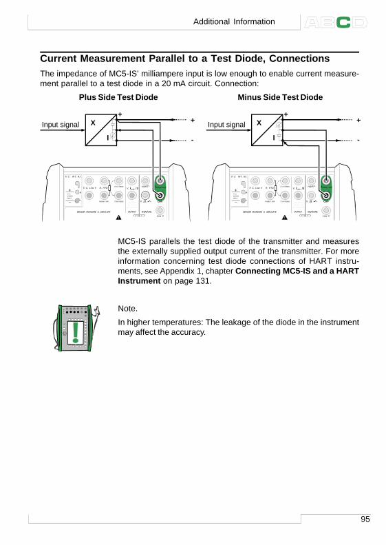
95
Current Measurement Parallel to a Test Diode, ConnectionsThe impedance of MC5-IS’ milliampere input is low enough to enable current measure-ment parallel to a test diode in a 20 mA circuit. Connection:
Plus Side Test Diode Minus Side Test Diode
MC5-IS parallels the test diode of the transmitter and measuresthe externally supplied output current of the transmitter. For moreinformation concerning test diode connections of HART instru-ments, see Appendix 1, chapter Connecting MC5-IS and a HARTInstrument on page 131.
Note.
In higher temperatures: The leakage of the diode in the instrumentmay affect the accuracy.
T/C, Low V HART® Imeas/sink
V, ,
V, I , sink
Com
R, RTD
Low V
MEASUREOUTPUT
ET E
T/C INT. RJ
SENSOR MEASURE & SIMULATE
Uo: 16 V Io: 24 mA
Po: 145 mW
T/C WIRES ONLY
4 w meas
3 w measmeas/sim
+
I
Input signal X +
-
Imeas/sink
Com
T/C, Low V HART® Imeas/sink
V, ,
V, I , sink
Com
R, RTD
Low V
MEASUREOUTPUT
ET E
T/C INT. RJ
SENSOR MEASURE & SIMULATE
Uo: 16 V Io: 24 mA
Po: 145 mW
T/C WIRES ONLY
4 w meas
3 w measmeas/sim
+
I
Input signal X +
-
Imeas/sink
Com
Additional Information
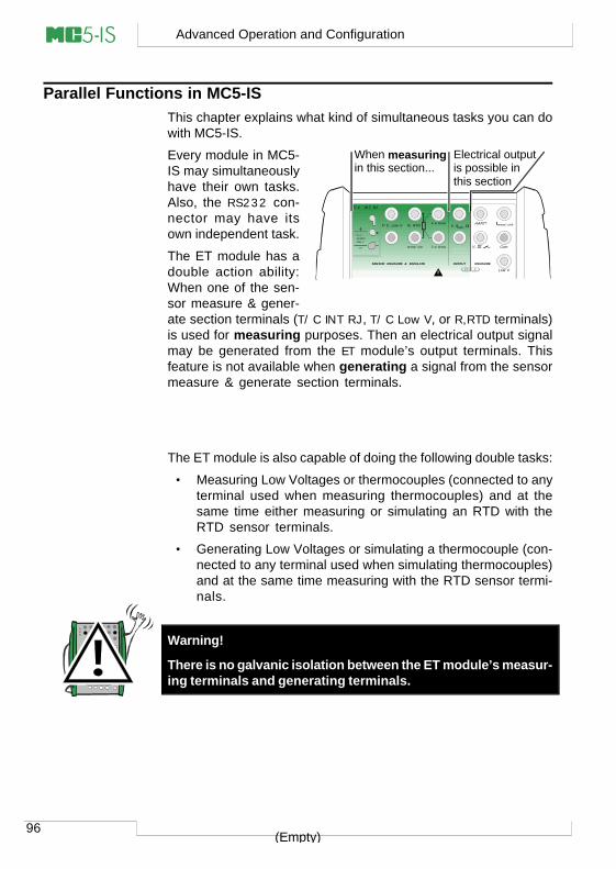
96
Advanced Operation and Configuration
Parallel Functions in MC5-ISThis chapter explains what kind of simultaneous tasks you can dowith MC5-IS.
Every module in MC5-IS may simultaneouslyhave their own tasks.Also, the RS232 con-nector may have itsown independent task.
The ET module has adouble action ability:When one of the sen-sor measure & gener-ate section terminals (T/C INT RJ, T/C Low V, or R,RTD terminals)is used for measuring purposes. Then an electrical output signalmay be generated from the ET module’s output terminals. Thisfeature is not available when generating a signal from the sensormeasure & generate section terminals.
The ET module is also capable of doing the following double tasks:
• Measuring Low Voltages or thermocouples (connected to anyterminal used when measuring thermocouples) and at thesame time either measuring or simulating an RTD with theRTD sensor terminals.
• Generating Low Voltages or simulating a thermocouple (con-nected to any terminal used when simulating thermocouples)and at the same time measuring with the RTD sensor termi-nals.
Warning!
There is no galvanic isolation between the ET module’s measur-ing terminals and generating terminals.
(Empty)
When measuring in this section...
Electrical outputis possible in this section
T/C, Low V HART® Imeas/sink
V, ,
V, I , sink
Com
R, RTD
Low V
MEASUREOUTPUT
ET E
T/C INT. RJ
SENSOR MEASURE & SIMULATE
Uo: 16 V Io: 24 mA
Po: 145 mW
T/C WIRES ONLY
4 w meas
3 w measmeas/sim

Calibration
Things discussed in Part D:
• General presentation of whatcalibration is and the phasesof a typical calibration proce-dure.
• A description of a calibrationprocedure using MC5-IS.
• Some application examples onhow to perform the calibrationof certain instruments.
• Creating, editing and deletingInstruments.
• Viewing calibration results.
98
Calibration
General
MC5-IS is a stand-alone calibrator as well as a calibrator communi-cating with calibration software.
MC5-IS supports stand-alone calibration and off-line calibration.The following list briefly describes these methods:
• In stand-alone calibration, all instrument and calibration resultdata is stored in MC5-IS’ memory. No external calibration da-tabase is used.
• In off-line calibration (sometimes also called batch calibration),the instrument data is downloaded from a calibration software.The calibration is done just as in stand-alone calibration, butcalibration procedures are downloaded from a software andthe saved results are uploaded to the calibration software.
Note that off-line calibration requires the QCAL option. It also re-quires the computer communication cable to connect MC5-IS to aPC’s serial port.
Note.
MC5-IS also includes a serial communication protocol option. Withthe option, it is possible to control MC5-IS via the RS232 port toperform, e.g. a remotely controlled calibration. The communicationprotocol specification can be obtained from Beamex.
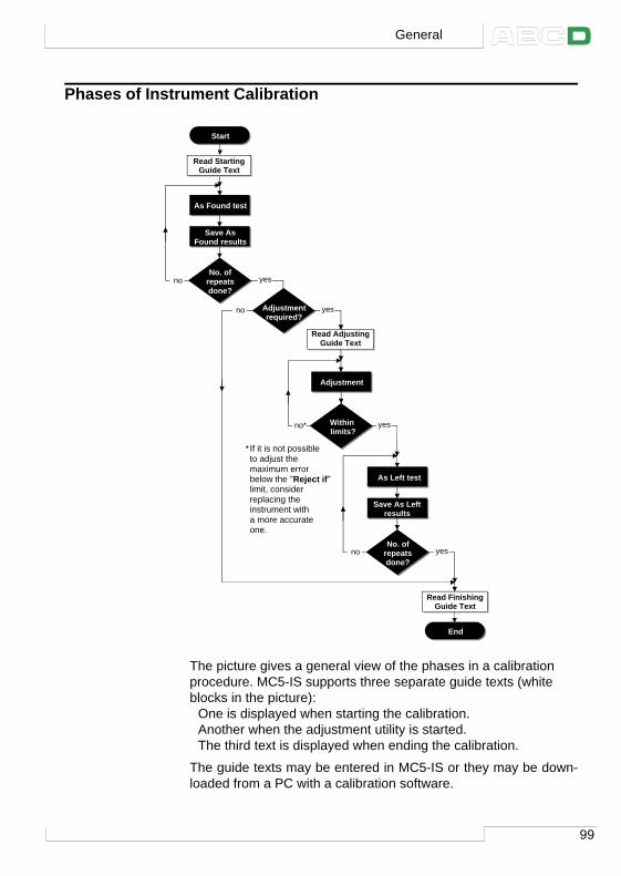
99
Phases of Instrument Calibration
The picture gives a general view of the phases in a calibrationprocedure. MC5-IS supports three separate guide texts (whiteblocks in the picture):
One is displayed when starting the calibration.Another when the adjustment utility is started.The third text is displayed when ending the calibration.
The guide texts may be entered in MC5-IS or they may be down-loaded from a PC with a calibration software.
Start
As Found test
Save As Found results
No. of repeatsdone?
Read Starting Guide Text
no yes
Adjustmentrequired?
Within limits?
As Left test
Adjustment
* If it is not possible to adjust the maximum error below the "Reject if" limit, consider replacing the instrument with a more accurate one.
Read Adjusting Guide Text
no
no* yes
yes
End
Save As Left results
No. of repeatsdone?
Read FinishingGuide Text
no yes
General
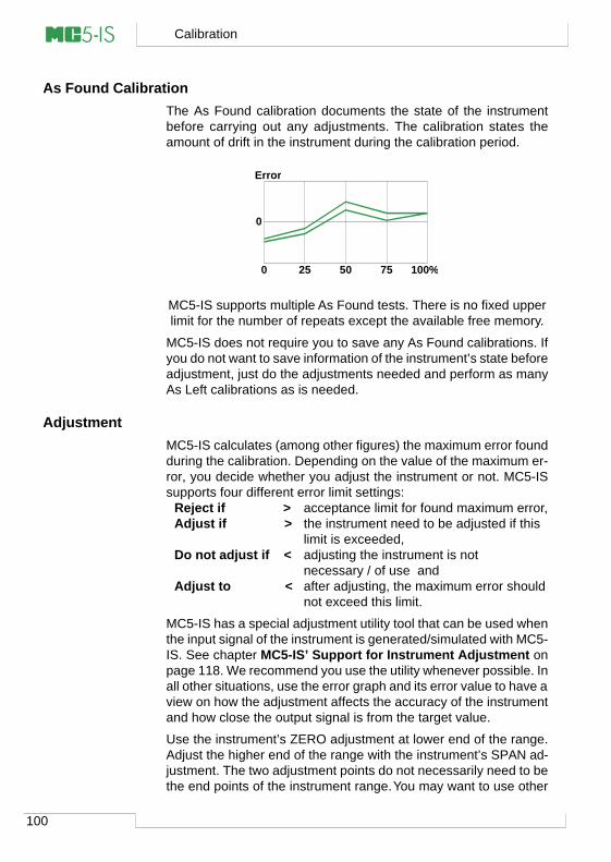
100
Calibration
As Found CalibrationThe As Found calibration documents the state of the instrumentbefore carrying out any adjustments. The calibration states theamount of drift in the instrument during the calibration period.
MC5-IS supports multiple As Found tests. There is no fixed upperlimit for the number of repeats except the available free memory.
MC5-IS does not require you to save any As Found calibrations. Ifyou do not want to save information of the instrument’s state beforeadjustment, just do the adjustments needed and perform as manyAs Left calibrations as is needed.
AdjustmentMC5-IS calculates (among other figures) the maximum error foundduring the calibration. Depending on the value of the maximum er-ror, you decide whether you adjust the instrument or not. MC5-ISsupports four different error limit settings:
Reject if > acceptance limit for found maximum error,Adjust if > the instrument need to be adjusted if this
limit is exceeded,Do not adjust if < adjusting the instrument is not
necessary / of use andAdjust to < after adjusting, the maximum error should
not exceed this limit.
MC5-IS has a special adjustment utility tool that can be used whenthe input signal of the instrument is generated/simulated with MC5-IS. See chapter MC5-IS’ Support for Instrument Adjustment onpage 118. We recommend you use the utility whenever possible. Inall other situations, use the error graph and its error value to have aview on how the adjustment affects the accuracy of the instrumentand how close the output signal is from the target value.
Use the instrument’s ZERO adjustment at lower end of the range.Adjust the higher end of the range with the instrument’s SPAN ad-justment. The two adjustment points do not necessarily need to bethe end points of the instrument range. You may want to use other
0
0 25 50 75 100%
Error
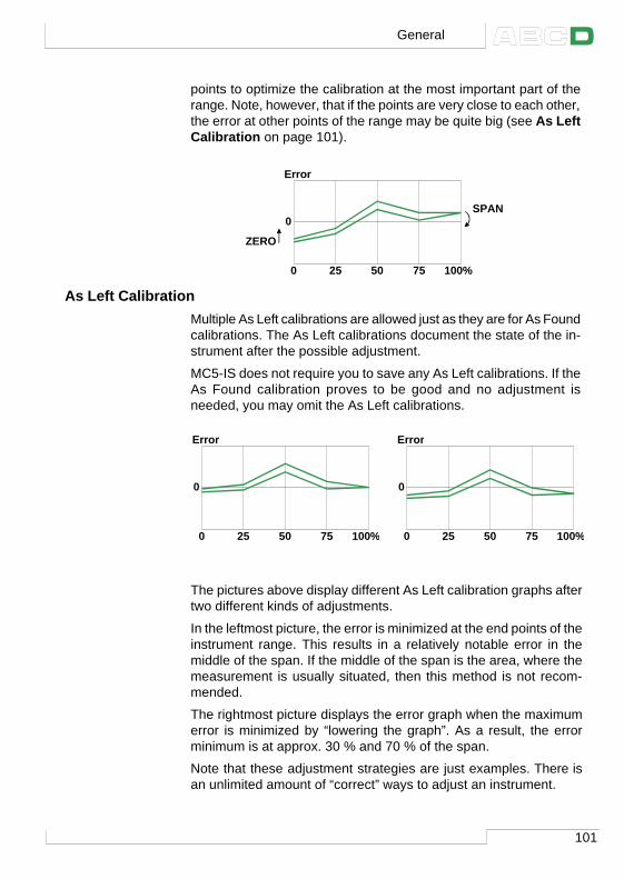
101
points to optimize the calibration at the most important part of therange. Note, however, that if the points are very close to each other,the error at other points of the range may be quite big (see As LeftCalibration on page 101).
As Left CalibrationMultiple As Left calibrations are allowed just as they are for As Foundcalibrations. The As Left calibrations document the state of the in-strument after the possible adjustment.
MC5-IS does not require you to save any As Left calibrations. If theAs Found calibration proves to be good and no adjustment isneeded, you may omit the As Left calibrations.
The pictures above display different As Left calibration graphs aftertwo different kinds of adjustments.
In the leftmost picture, the error is minimized at the end points of theinstrument range. This results in a relatively notable error in themiddle of the span. If the middle of the span is the area, where themeasurement is usually situated, then this method is not recom-mended.
The rightmost picture displays the error graph when the maximumerror is minimized by “lowering the graph”. As a result, the errorminimum is at approx. 30 % and 70 % of the span.
Note that these adjustment strategies are just examples. There isan unlimited amount of “correct” ways to adjust an instrument.
ZERO
SPAN0
0 25 50 75 100%
Error
0
0 25 50 75 100%
Error
0
0 25 50 75 100%
Error
General
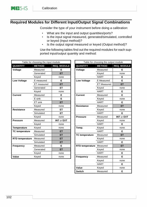
102
Calibration
Required Modules for Different Input/Output Signal CombinationsConsider the type of your instrument before doing a calibration:
• What are the input and output quantities/ports?• Is the input signal measured, generated/simulated, controlled
or keyed (Input method)?• Is the output signal measured or keyed (Output method)?
Use the following tables find out the required modules for each sup-ported input/output quantity and method:
Table for choosing the input module Table for choosing the output module QUANTITY METHOD REQ. MODULE QUANTITY METHOD REQ. MODULE Voltage Measured E Voltage Measured E
Generated ET Keyed none Keyed none HART E
Low Voltage E measured E Low Voltage E Measured E ET measured ET ET Measured ET Generated ET Keyed none Keyed none HART E
Current Measured E Current Measured E E sink E Keyed none ET sink ET HART E Keyed none Resistance Measured ET
Resistance Measured ET Keyed none Simulated ET HART E Keyed none Pressure Measured INT or EXT
Pressure Measured INT or EXT Keyed none Keyed none HART E
Temperature Keyed none Temp. Keyed none TC temperature Measured ET HART E
Simulated ET TC temperature Measured ET RTD temperature Measured ET Keyed none
Simulated ET HART E Frequency Measured E RTD temperature Measured ET
Generated ET Keyed none Keyed none HART E
Value Keyed none Frequency Measured E Keyed none HART E
Value Keyed none Switch Measured E
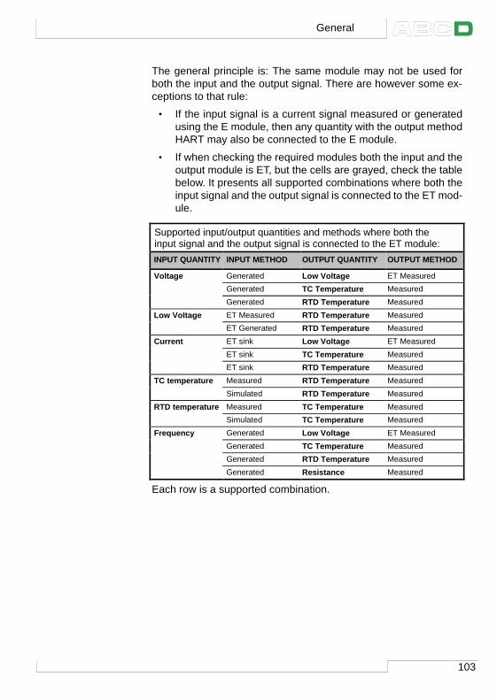
103
The general principle is: The same module may not be used forboth the input and the output signal. There are however some ex-ceptions to that rule:
• If the input signal is a current signal measured or generatedusing the E module, then any quantity with the output methodHART may also be connected to the E module.
• If when checking the required modules both the input and theoutput module is ET, but the cells are grayed, check the tablebelow. It presents all supported combinations where both theinput signal and the output signal is connected to the ET mod-ule.
Each row is a supported combination.
General
Supported input/output quantities and methods where both the input signal and the output signal is connected to the ET module: INPUT QUANTITY INPUT METHOD OUTPUT QUANTITY OUTPUT METHOD
Voltage Generated Low Voltage ET Measured Generated TC Temperature Measured Generated RTD Temperature Measured
Low Voltage ET Measured RTD Temperature Measured ET Generated RTD Temperature Measured
Current ET sink Low Voltage ET Measured ET sink TC Temperature Measured ET sink RTD Temperature Measured
TC temperature Measured RTD Temperature Measured Simulated RTD Temperature Measured
RTD temperature Measured TC Temperature Measured Simulated TC Temperature Measured
Frequency Generated Low Voltage ET Measured Generated TC Temperature Measured Generated RTD Temperature Measured Generated Resistance Measured
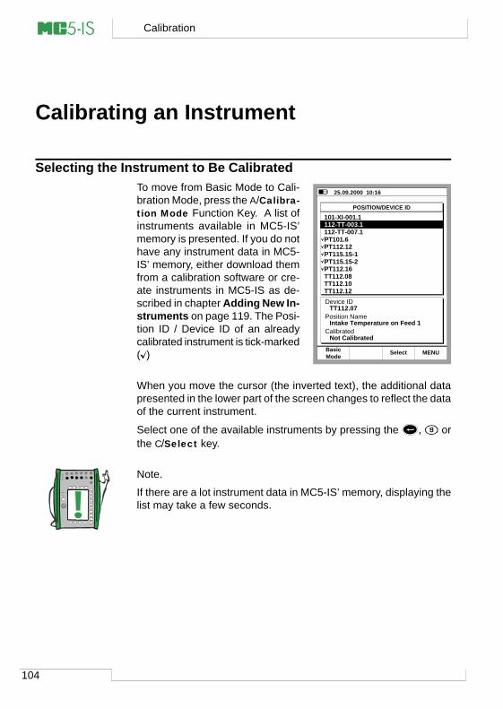
104
Calibration
Calibrating an Instrument
Selecting the Instrument to Be CalibratedTo move from Basic Mode to Cali-bration Mode, press the A/Calibra-tion Mode Function Key. A list ofinstruments available in MC5-IS’memory is presented. If you do nothave any instrument data in MC5-IS’ memory, either download themfrom a calibration software or cre-ate instruments in MC5-IS as de-scribed in chapter Adding New In-struments on page 119. The Posi-tion ID / Device ID of an alreadycalibrated instrument is tick-marked( )
When you move the cursor (the inverted text), the additional datapresented in the lower part of the screen changes to reflect the dataof the current instrument.
Select one of the available instruments by pressing the , orthe C/Select key.
Note.
If there are a lot instrument data in MC5-IS’ memory, displaying thelist may take a few seconds.
25.09.2000 10:16
POSITION/DEVICE ID
101-XI-001.1112-TT-003.1112-TT-007.1PT101.6PT112.12PT115.15-1PT115.15-2PT112.16TT112.08TT112.10TT112.12Device ID
Position Name
Calibrated
TT112.07
Intake Temperature on Feed 1
Not Calibrated
ModeBasic MENUSelect
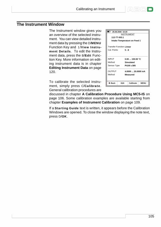
105
The Instrument WindowThe Instrument window gives youan overview of the selected instru-ment. You can view detailed instru-ment data by pressing the D/MENUFunction Key and 1/View Instru-ment Details. To edit the Instru-ment data, press the B/Edit Func-tion Key. More information on edit-ing instrument data is in chapterEditing Instrument Data on page120.
To calibrate the selected instru-ment, simply press C/Calibrate.General calibration procedures arediscussed in chapter A Calibration Procedure Using MC5-IS onpage 106. Some calibration examples are available starting fromchapter Examples of Instrument Calibration on page 109.
If a Starting Guide text is written, it appears before the CalibrationWindows are opened. To close the window displaying the note text,press D/OK.
25.09.2000 10:20 INSTRUMENT
112-TT-003.1
Edit Calibrate MENU
Intake Temperature on Feed 1
Cal. Points 5 ↑↓
Transfer Function Linear
Method SimulatedINPUT 0.00 ... 100.00 °C
Sensor Type Pt100 α385
Method MeasuredOUTPUT 4.0000 ... 20.0000 mA
Back
Calibrating an Instrument
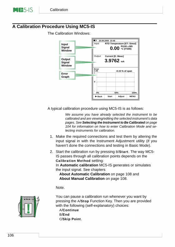
106
Calibration
A Calibration Procedure Using MC5-ISThe Calibration Windows:
A typical calibration procedure using MC5-IS is as follows:We assume you have already selected the instrument to becalibrated and are viewing/editing the selected instrument’s datapages. See Selecting the Instrument to Be Calibrated on page104 for information on how to enter Calibration Mode and se-lecting instruments for calibration.
1. Make the required connections and test them by altering theinput signal in with the Instrument Adjustment utility (if youhaven’t done the connections and testing in Basic Mode).
2. Start the calibration run by pressing B/Start. The way MC5-IS passes through all calibration points depends on theCalibration Method setting:In Automatic calibration MC5-IS generates or simulatesthe input signal. See chapters
About Automatic Calibration on page 108 andAbout Manual Calibration on page 108.
Note.
You can pause a calibration run whenever you want bypressing the A/Stop Function Key. Then you are providedwith the following (self-explanatory) choices:
A/ContinueB/EndC/Skip Point.
25.09.2000 10:46 Input
Error1.00
Output
Pt100 α385°C (ITS90)
3.9762
-0.15 % of span
0.00
+
0
-0% 50% 100%
RTD Temperature [ET: Simul]
Current [E: Meas]
mA
Start MENU Back Adjust
Input Signal Window
ErrorGraph
Output Signal Window
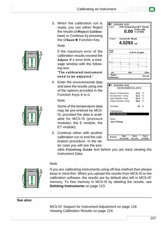
107
3. When the calibration run isready, you can either Rejectthe results (A/Reject Calibra-tion) or Continue by pressingthe D/Saveè Function Key.
Note.
If the maximum error of thecalibration results exceed theAdjust if > error limit, a mes-sage window with the follow-ing text:”The calibrated instrumentneed to be adjusted.”
4. Enter the environmental dataand save the results using oneof the options provided in theFunction Keys B to D.
Note.
Some of the temperature datamay be pre-entered by MC5-IS, provided the data is avail-able for MC5-IS (pressuremodules, the E module, theET module).
5. Continue either with anothercalibration run or end the cali-bration procedure. In the lat-ter case you will see the pos-sible Finishing Guide text before you are back viewing theInstrument Data.
Note.
If you are calibrating instruments using off-line method then pleasekeep in mind this: When you upload the results from MC5-IS to thecalibration software, the results are by default also left in MC5-IS’memory. To free memory in MC5-IS by deleting the results, seeDeleting Instruments on page 123.
See also:
MC5-IS’ Support for Instrument Adjustment on page 118.Viewing Calibration Results on page 124.
25.09.2000 10:52 Input
Error1.00
Output
Pt100 α385°C (ITS90)
4.0293
0.18 % of span
0.00
+
0
-0% 50% 100%
RTD Temperature [ET: Simul]
Current [E: Meas]
mA
CalibrationReject Save
25.09.2000 10:55 ENVIRONMENTAL DATA
Device TemperatureEnvironment Temp.Input Module Temp.Output Module Temp.
Humidity
Calibrated by:
Notes:
Andy Handyman
Just Testing
21.021.031.629.6
°C°C°C°C
30 %
As FoundSave
As LeftSave
As BothSave Back
Calibrating an Instrument
108
Calibration
About Automatic CalibrationAutomatic calibration is possible when MC5-IS is able to generate/simulate the input signal.
Automatic calibration is selected in the Calibration Method fieldon the Instrument Data pages. More information on editing instru-ment data is in chapter Editing Instrument Data on page 120.
In Automatic calibration MC5-IS generates/simulates the inputsignal. When the input signal is within the Maximum Allowed Cali-bration Point Deviation limits, MC5-IS waits for the output signalto stabilize (the Setpoint Delay setting). Then the calibration pointis accepted automatically and MC5-IS continues with the next cali-bration point.
If the input signal never stabilizes (the symbol is visible con-tinuously), but you want MC5-IS to save the results anyhow, pressthe B/Force Accept Function Key.
About Manual CalibrationIn manual calibration, you will have to manually set the input signalto a level that the next calibration point requires. Manual calibrationis possible in almost all situations. Even for calibrations that couldbe done automatically.
If the input signal is measured, the input signal window displays a“Desired Input Value X.xxxx” text to help you remember what isthe next target value.
If the input signal is generated/simulated, MC5-IS automaticallychanges the input signal to the next target value, but does not con-tinue until you manually accept the point.
Use the B/Accept Readings Function Key to save the point dataand continue to the next point until all points are accepted.
Note.
If the calibration points are defined for the output signal, set theinput signal to such a level that the instrument to be calibrated cre-ates the required output signal.
109
Autocapture FeatureThe Autocapture Feature makes it possible to make a manual cali-bration that is semi-automatic when the input signal in measured.To be able to utilize the Autocapture Feature the instrument datahas to be set as follows:
• Input Method field set to “Measured”,• Calibration Method field set to “Automatic” and• Maximum Allowed Calibration Point Deviation field set to
greater than zero.
Then MC5-IS tracks the input signal and once the input signal isinside the Maximum Allowed Calibration Point Deviation limitfor a time period defined in the Setpoint Delay, the input and out-put values are automatically saved.
Activate the Autocapture Feature from the menu available whenviewing the calibration windows. When activated and a calibrationpoint is about to be captured (MC5-IS is waiting for the SetpointDelay time to pass while the measurements are stable enough andwithin the Maximum Allowed Calibration Point Deviation limit),an hourglass is shown in the input measurement window’s lowerright corner.
When autocapture “snatches” the input and output signal values,MC5-IS emits a beep and the next target value for the input is dis-played.
Examples of Instrument CalibrationThis User Guide has only a few examples of how to calibrate aninstrument. Many calibration procedures not presented here areeither very similar to the ones presented in the following chaptersor they can be “combined”, e.g. the calibration of a Pressure Indi-cator/Recorder is partly done as a Pressure Transmitter and partlyas a Temperature Indicator/Recorder calibration.
Use the information presented in Part B of this manual when con-necting/calibrating instruments that do not have a separate calibra-tion procedure presented in this part.
The calibration of the following instruments are presented in thismanual:
Pressure Transmitters on page 110,Temperature Sensors on page 112,Temperature Indicators and Recorders on page 114 andElectrical Limit Switches on page 116.
Calibrating an Instrument
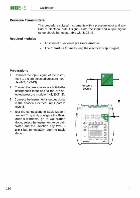
110
Calibration
Pressure TransmittersThis procedure suits all instruments with a pressure input and anykind of electrical output signal. Both the input and output signalrange should be measurable with MC5-IS.
Required modules• An internal or external pressure module.• The E module for measuring the electrical output signal.
Preparations1. Connect the input signal of the instru-
ment to the pre-selected pressure mod-ule (INT, EXT-IS).
2. Connect the pressure source both to theinstrument’s input and to the pre-se-lected pressure module (INT, EXT-IS).
3. Connect the instrument’s output signalto the chosen electrical input port inMC5-IS.
4. Test the connections in Basic Mode ifneeded. To quickly configure the BasicMode’s windows, go to CalibrationMode, select the instrument to be cali-brated and the Function Key C/Cali-brate but immediately return to BasicMode.
P
EPressureSource
0 6 . 1 0 . 2 0 0 0 1 1 : 4 9 I n p u t
E r r o r1 . 0 0
O u t p u t
G a u g eb a r
8 . 0 3 1 0
0 . 2 8 % o f s p a n
0 . 4 9 8 2
+
0
-0 % 5 0 % 1 0 0 %
P r e s s u r e [ P 1 : I N T 6 C ]
C u r r e n t [ E : M e a s ]
m A
P a u s eR e a d i n g s
A c c e p t
D e s i r e d I n p u t V a l u e 0 . 5 0 0 0
T / C , L o w V H A R T ® I m e a s / s i n k
V , ,
V , I , s i n k
C o m
R , R T D
?
M U L T I F U N C T I O N C A L I B R A T O R
L o w V
M E A S U R EO U T P U T
E T E
T / C I N T . R J
S E N S O R M E A S U R E & S I M U L A T E
U o : 1 6 V I o : 2 4 m A
P o : 1 4 5 m W
T / C W I R E SO N L Y
I I 1 G
E E x i a I I C T 4(T a m b = 5 0 ° C )
V T T 0 2 A T E X 0 0 3 X
E x i a I I C T 4(T a m b = 5 0 ° C )
V T T N o . E x - 0 2 . 0 1 1 X
U i : 3 0 V Ii : 2 1 5 m A
P i : 1 W
I N P U T
4 w m e a s
3 w m e a sm e a s / s i m
111
Calibration1. Move to Calibration Mode and select the
instrument to be calibrated.
2. Start the calibration as presented inchapter A Calibration Procedure Us-ing MC5-IS on page 106.
3. Set the pressure manually using, e.g.a pressure pump.
4. Accept the points using the B/AcceptReadings Function Key.
5. Save or reject the results as is de-scribed in chapter A Calibration Pro-cedure Using MC5-IS on page 106.
6. Either do another calibration run or re-turn to the Instrument window.
Hint!
These instructions can be adapted for pneumatic pressure trans-mitters and converters, too. Instead of connecting the output sig-nal to a terminal in the E module, connect the pressure output sig-nal to a suitable pressure module.
Warning!
Working with pressure instruments can be hazardous. Onlyqualified personnel may use pressure instruments and pres-sure sources.
Next…
MC5-IS’ Support for Instrument Adjustment on page 118
Calibrating an Instrument
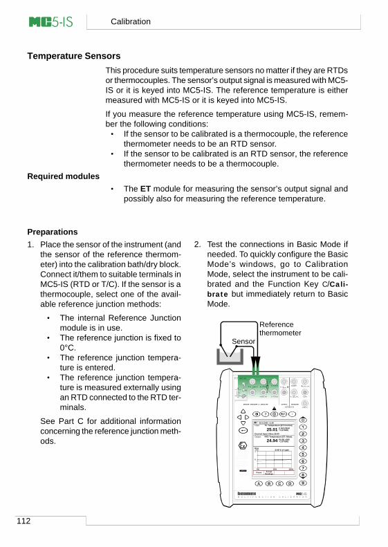
112
Calibration
Temperature SensorsThis procedure suits temperature sensors no matter if they are RTDsor thermocouples. The sensor’s output signal is measured with MC5-IS or it is keyed into MC5-IS. The reference temperature is eithermeasured with MC5-IS or it is keyed into MC5-IS.
If you measure the reference temperature using MC5-IS, remem-ber the following conditions:
• If the sensor to be calibrated is a thermocouple, the referencethermometer needs to be an RTD sensor.
• If the sensor to be calibrated is an RTD sensor, the referencethermometer needs to be a thermocouple.
Required modules• The ET module for measuring the sensor’s output signal and
possibly also for measuring the reference temperature.
Preparations1. Place the sensor of the instrument (and
the sensor of the reference thermom-eter) into the calibration bath/dry block.Connect it/them to suitable terminals inMC5-IS (RTD or T/C). If the sensor is athermocouple, select one of the avail-able reference junction methods:
• The internal Reference Junctionmodule is in use.
• The reference junction is fixed to0°C.
• The reference junction tempera-ture is entered.
• The reference junction tempera-ture is measured externally usingan RTD connected to the RTD ter-minals.
See Part C for additional informationconcerning the reference junction meth-ods.
2. Test the connections in Basic Mode ifneeded. To quickly configure the BasicMode’s windows, go to CalibrationMode, select the instrument to be cali-brated and the Function Key C/Cali-brate but immediately return to BasicMode.
Referencethermometer
Sensor
06.10.2000 11:06 Input
Error1.00
Output
°C (ITS90)
24.94
-0.06 % of span
25.01
+
0
-0% 50% 100%
TC Temperature [ET:Control]
RTD Temperature [ET: Meas]
°C (ITS90)
PauseReadings
Accept
Desired Input Value 25.00
Pt100 α385
K NiCr/NiAl
M U L T I F U N C T I O N C A L I B R A T O R
T/C, Low V HART® Imeas/sink
V, ,
V, I , sink
Com
R, RTD
?
Low V
MEASUREOUTPUT
ET E
T/C INT. RJ
SENSOR MEASURE & SIMULATE
Uo: 16 V Io: 24 mA
Po: 145 mW
T/C WIRESONLY
II 1 G
EEx ia IIC T4(Tamb = 50°C)
VTT 02 ATEX 003 X
Ex ia IIC T4(Tamb = 50°C)
VTT No. Ex-02.011 X
Ui: 30 V Ii: 215 mA
Pi: 1 W
INPUT
4 w meas
3 w measmeas/sim
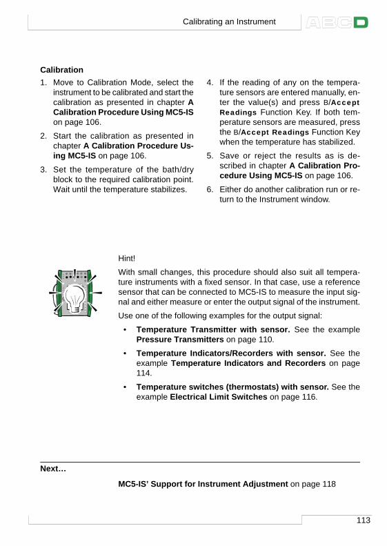
113
Calibration1. Move to Calibration Mode, select the
instrument to be calibrated and start thecalibration as presented in chapter ACalibration Procedure Using MC5-ISon page 106.
2. Start the calibration as presented inchapter A Calibration Procedure Us-ing MC5-IS on page 106.
3. Set the temperature of the bath/dryblock to the required calibration point.Wait until the temperature stabilizes.
4. If the reading of any on the tempera-ture sensors are entered manually, en-ter the value(s) and press B/AcceptReadings Function Key. If both tem-perature sensors are measured, pressthe B/Accept Readings Function Keywhen the temperature has stabilized.
5. Save or reject the results as is de-scribed in chapter A Calibration Pro-cedure Using MC5-IS on page 106.
6. Either do another calibration run or re-turn to the Instrument window.
Hint!
With small changes, this procedure should also suit all tempera-ture instruments with a fixed sensor. In that case, use a referencesensor that can be connected to MC5-IS to measure the input sig-nal and either measure or enter the output signal of the instrument.
Use one of the following examples for the output signal:
• Temperature Transmitter with sensor. See the examplePressure Transmitters on page 110.
• Temperature Indicators/Recorders with sensor. See theexample Temperature Indicators and Recorders on page114.
• Temperature switches (thermostats) with sensor. See theexample Electrical Limit Switches on page 116.
Next…
MC5-IS’ Support for Instrument Adjustment on page 118
Calibrating an Instrument
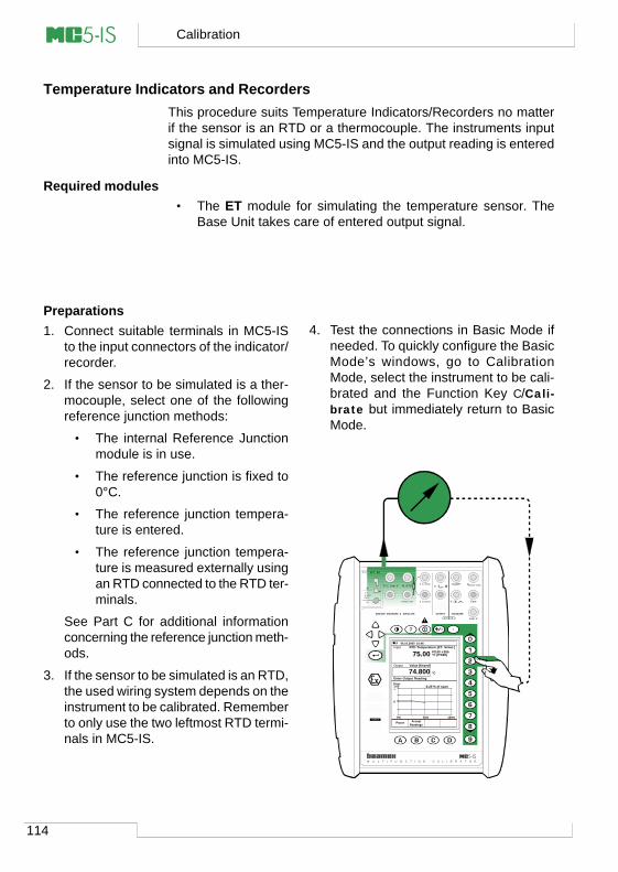
114
Calibration
Temperature Indicators and RecordersThis procedure suits Temperature Indicators/Recorders no matterif the sensor is an RTD or a thermocouple. The instruments inputsignal is simulated using MC5-IS and the output reading is enteredinto MC5-IS.
Required modules• The ET module for simulating the temperature sensor. The
Base Unit takes care of entered output signal.
Preparations1. Connect suitable terminals in MC5-IS
to the input connectors of the indicator/recorder.
2. If the sensor to be simulated is a ther-mocouple, select one of the followingreference junction methods:
• The internal Reference Junctionmodule is in use.
• The reference junction is fixed to0°C.
• The reference junction tempera-ture is entered.
• The reference junction tempera-ture is measured externally usingan RTD connected to the RTD ter-minals.
See Part C for additional informationconcerning the reference junction meth-ods.
3. If the sensor to be simulated is an RTD,the used wiring system depends on theinstrument to be calibrated. Rememberto only use the two leftmost RTD termi-nals in MC5-IS.
4. Test the connections in Basic Mode ifneeded. To quickly configure the BasicMode’s windows, go to CalibrationMode, select the instrument to be cali-brated and the Function Key C/Cali-brate but immediately return to BasicMode.
06.10.2000 10:46 Input
Error1.00
Output
°C (ITS90)
74.800
-0.20 % of span
75.00
+
0
-0% 50% 100%
RTD Temperature [ET: Simul.]
Value [Keyed]
°C
PauseReadings
Accept
Pt100 α385
Enter Output Reading
M U L T I F U N C T I O N C A L I B R A T O R
T/C, Low V HART® Imeas/sink
V, ,
V, I , sink
Com
R, RTD
?
Low V
MEASUREOUTPUT
ET E
T/C INT. RJ
SENSOR MEASURE & SIMULATE
Uo: 16 V Io: 24 mA
Po: 145 mW
T/C WIRESONLY
II 1 G
EEx ia IIC T4(Tamb = 50°C)
VTT 02 ATEX 003 X
Ex ia IIC T4(Tamb = 50°C)
VTT No. Ex-02.011 X
Ui: 30 V Ii: 215 mA
Pi: 1 W
INPUT
4 w meas
3 w measmeas/sim
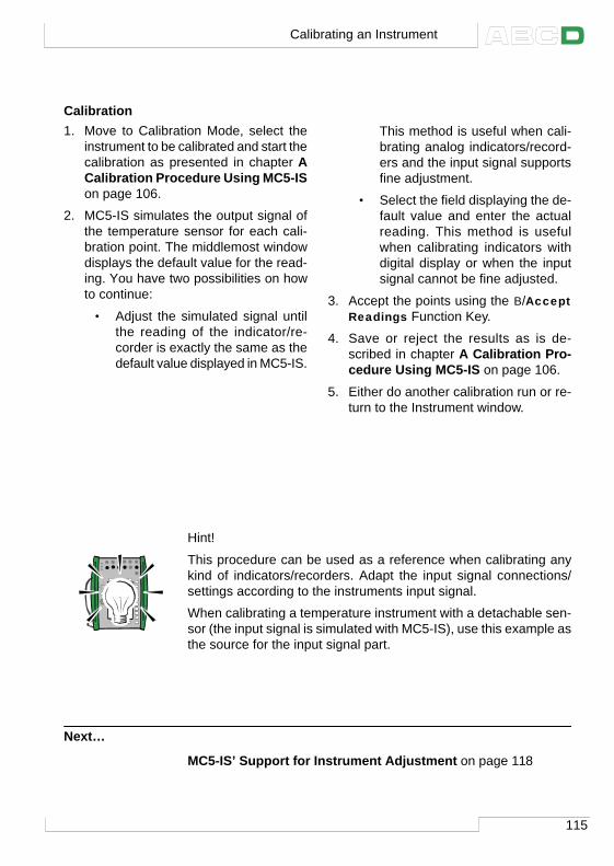
115
Calibration1. Move to Calibration Mode, select the
instrument to be calibrated and start thecalibration as presented in chapter ACalibration Procedure Using MC5-ISon page 106.
2. MC5-IS simulates the output signal ofthe temperature sensor for each cali-bration point. The middlemost windowdisplays the default value for the read-ing. You have two possibilities on howto continue:
• Adjust the simulated signal untilthe reading of the indicator/re-corder is exactly the same as thedefault value displayed in MC5-IS.
This method is useful when cali-brating analog indicators/record-ers and the input signal supportsfine adjustment.
• Select the field displaying the de-fault value and enter the actualreading. This method is usefulwhen calibrating indicators withdigital display or when the inputsignal cannot be fine adjusted.
3. Accept the points using the B/AcceptReadings Function Key.
4. Save or reject the results as is de-scribed in chapter A Calibration Pro-cedure Using MC5-IS on page 106.
5. Either do another calibration run or re-turn to the Instrument window.
Hint!
This procedure can be used as a reference when calibrating anykind of indicators/recorders. Adapt the input signal connections/settings according to the instruments input signal.
When calibrating a temperature instrument with a detachable sen-sor (the input signal is simulated with MC5-IS), use this example asthe source for the input signal part.
Next…
MC5-IS’ Support for Instrument Adjustment on page 118
Calibrating an Instrument
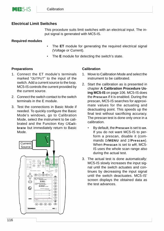
116
Calibration
Electrical Limit SwitchesThis procedure suits limit switches with an electrical input. The in-put signal is generated with MC5-IS.
Required modules• The ET module for generating the required electrical signal
(Voltage or Current).
• The E module for detecting the switch’s state.
Preparations1. Connect the ET module’s terminals
marked “OUTPUT” to the input of theswitch. Add a current source to the loop.MC5-IS controls the current provided bythe current source.
2. Connect the switch contact to the switchterminals in the E module.
3. Test the connections in Basic Mode ifneeded. To quickly configure the BasicMode’s windows, go to CalibrationMode, select the instrument to be cali-brated and the Function Key C/Cali-brate but immediately return to BasicMode.
Calibration1. Move to Calibration Mode and select the
instrument to be calibrated.
2. Start the calibration as is presented inchapter A Calibration Procedure Us-ing MC5-IS on page 106. MC5-IS doesthe Prescan if it is enabled. During theprescan, MC5-IS searches for approxi-mate values for the actuating anddeactuating point. This speeds up thefinal test without sacrificing accuracy.The prescan test is done only once in acalibration.
• By default, the Prescan is set to on.If you do not want MC5-IS to per-form a prescan, disable it (com-mands D/MENU and 2/Prescan).When Prescan is set to off, MC5-IS uses the whole scan range alsoduring the actual test.
3. The actual test is done automatically:MC5-IS slowly increases the input sig-nal until the switch actuates and con-tinues by decreasing the input signaluntil the switch deactuates. MC5-IS’screen displays the obtained data asthe test advances.
06.10.2000 10:29 Input
Output
V
8.0310
5.023Voltage [ET: Gen.]
Switch [E: Meas.]
Actuate
Pause
Testing switch limits (4/5)
Deactuate-------7.000
5.500
4.500
3.000
CurrentSource
M U L T I F U N C T I O N C A L I B R A T O R
T/C, Low V HART® Imeas/sink
V, ,
V, I , sink
Com
R, RTD
?
Low V
MEASUREOUTPUT
ET E
T/C INT. RJ
SENSOR MEASURE & SIMULATE
Uo: 16 V Io: 24 mA
Po: 145 mW
T/C WIRESONLY
II 1 G
EEx ia IIC T4(Tamb = 50°C)
VTT 02 ATEX 003 X
Ex ia IIC T4(Tamb = 50°C)
VTT No. Ex-02.011 X
Ui: 30 V Ii: 215 mA
Pi: 1 W
INPUT
4 w meas
3 w measmeas/sim
117
• If for some reason the calibrationcannot be done automatically (be-cause the input signal is measured,not generated/simulated), you willhave to change the input signalmanually. The slower you raise theinput signal the more accurate theobserved actuation point is. Beequally careful when decreasing theinput signal in order to get thedeactuation point.
4. Save or reject the results as is de-scribed in chapter A Calibration Pro-cedure Using MC5-IS on page 106.
5. Either do another calibration run or re-turn to the Instrument window.
Notes.
Selecting Calibration Method Manual when the input signal is gen-erated/simulated with MC5-IS means that each pair of actuation/deactuation points have to be accepted manually.
If the prescan stops and displays an error message, try wideningthe scan range. It is also advisable to have the scan range sym-metrical in relation to the actuation/deactuation points.
Hint!
This procedure also suits other types of switches. How to calibrateother types of switches may be adapted by combining the informa-tion of this example with the input signal information from one of thefollowing examples:
• Pressure switches. See the example Pressure Transmit-ters on page 110.
• Temperature switches with a fixed sensor. See the exampleTemperature Sensors on page 112.
• Temperature switches with a detachable sensor. See theexample Temperature Indicators and Recorders on page114.
Next…
MC5-IS’ Support for Instrument Adjustment on page 118
Calibrating an Instrument
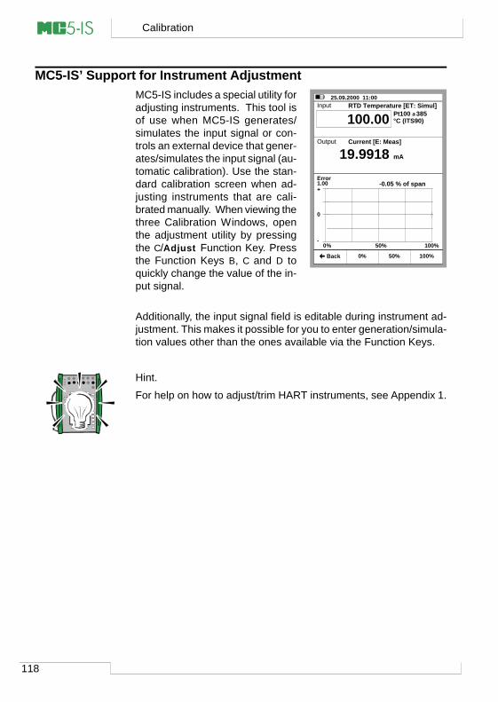
118
Calibration
MC5-IS’ Support for Instrument AdjustmentMC5-IS includes a special utility foradjusting instruments. This tool isof use when MC5-IS generates/simulates the input signal or con-trols an external device that gener-ates/simulates the input signal (au-tomatic calibration). Use the stan-dard calibration screen when ad-justing instruments that are cali-brated manually. When viewing thethree Calibration Windows, openthe adjustment utility by pressingthe C/Adjust Function Key. Pressthe Function Keys B, C and D toquickly change the value of the in-put signal.
Additionally, the input signal field is editable during instrument ad-justment. This makes it possible for you to enter generation/simula-tion values other than the ones available via the Function Keys.
Hint.
For help on how to adjust/trim HART instruments, see Appendix 1.
25.09.2000 11:00 Input
Error1.00
Output
Pt100 α385°C (ITS90)
19.9918
-0.05 % of span
100.00
+
0
-0% 50% 100%
RTD Temperature [ET: Simul]
Current [E: Meas]
mA
0% 100% Back 50%
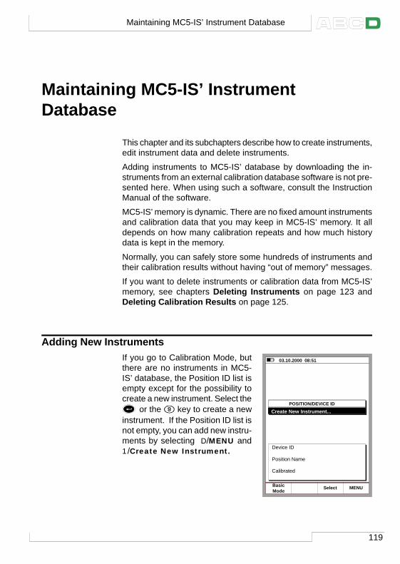
119
Maintaining MC5-IS’ InstrumentDatabase
This chapter and its subchapters describe how to create instruments,edit instrument data and delete instruments.
Adding instruments to MC5-IS’ database by downloading the in-struments from an external calibration database software is not pre-sented here. When using such a software, consult the InstructionManual of the software.
MC5-IS’ memory is dynamic. There are no fixed amount instrumentsand calibration data that you may keep in MC5-IS’ memory. It alldepends on how many calibration repeats and how much historydata is kept in the memory.
Normally, you can safely store some hundreds of instruments andtheir calibration results without having “out of memory” messages.
If you want to delete instruments or calibration data from MC5-IS’memory, see chapters Deleting Instruments on page 123 andDeleting Calibration Results on page 125.
Adding New InstrumentsIf you go to Calibration Mode, butthere are no instruments in MC5-IS’ database, the Position ID list isempty except for the possibility tocreate a new instrument. Select the
or the key to create a new
instrument. If the Position ID list isnot empty, you can add new instru-ments by selecting D/MENU and1/Create New Instrument.
03.10.2000 08:51
POSITION/DEVICE IDCreate New Instrument...
Device ID
Position Name
Calibrated
ModeBasic MENUSelect
Maintaining MC5-IS’ Instrument Database
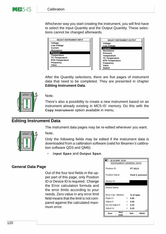
120
Calibration
Whichever way you start creating the instrument, you will first haveto select the Input Quantity and the Output Quantity. These selec-tions cannot be changed afterwards.
After the Quantity selections, there are five pages of instrumentdata that need to be completed. They are presented in chapterEditing Instrument Data.
Note.
There’s also a possibility to create a new instrument based on aninstrument already existing in MC5-IS’ memory. Do this with theCopy Instrument option available in menu.
Editing Instrument DataThe instrument data pages may be re-edited whenever you want.
Note.
Only the following fields may be edited if the instrument data isdownloaded from a calibration software (valid for Beamex’s calibra-tion software QD3 and QM6):
• Input Span and Output Span.
General Data PageOut of the four text fields in the up-per part of this page, only PositionID or Device ID is required. Changethe Error calculation formula andthe error limits according to yourneeds. Zero value in any error limitfield means that the limit is not com-pared against the calculated maxi-mum error.
SELECT INSTRUMENT INPUTVoltageLow VoltageCurrentResistancePressureTemperatureTC TemperatureRTD TemperatureFrequencyValue
SELECT INSTRUMENT OUTPUT
VoltageLow VoltageCurrentResistancePressureTemperatureTC TemperatureRTD TemperatureFrequencyValueSwitch
19.10.2000 10:04
Position ID
MENU
PT 101.6
Position Name Feed 3, pressure
Device ID
Device Name
Error Calc. Method % of spanReject if 0.50Adjust if 0.30Do not Adjust if 0.10Adjust to 0.10
>><<
SavepageNext Edit
INSTRUMENT GENERAL DATA
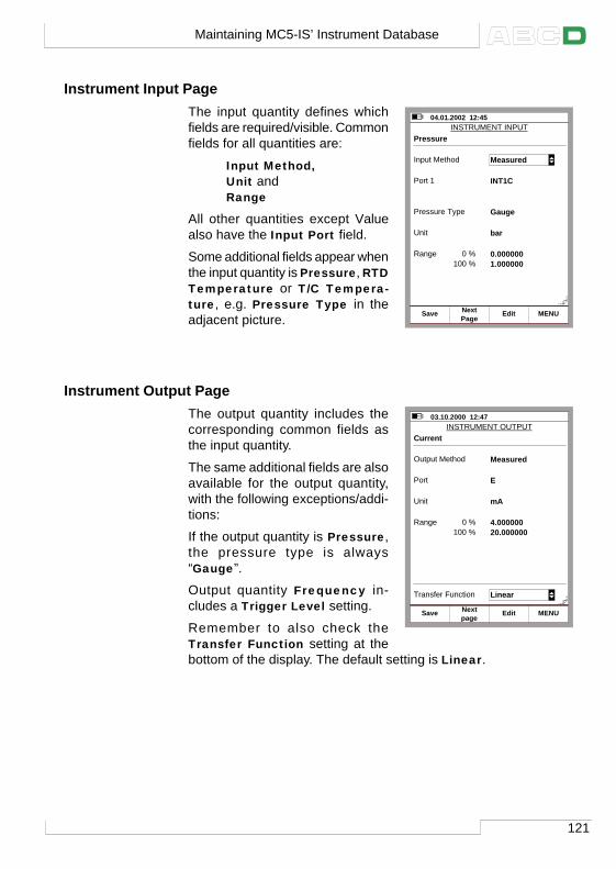
121
Instrument Input PageThe input quantity defines whichfields are required/visible. Commonfields for all quantities are:
Input Method,Unit andRange
All other quantities except Valuealso have the Input Port field.
Some additional fields appear whenthe input quantity is Pressure, RTDTemperature or T/C Tempera-ture, e.g. Pressure Type in theadjacent picture.
Instrument Output PageThe output quantity includes thecorresponding common fields asthe input quantity.
The same additional fields are alsoavailable for the output quantity,with the following exceptions/addi-tions:
If the output quantity is Pressure,the pressure type is always“Gauge”.
Output quantity Frequency in-cludes a Trigger Level setting.
Remember to also check theTransfer Function setting at thebottom of the display. The default setting is Linear.
04.01.2002 12:45INSTRUMENT INPUT
MENU
Input Method Measured
Unit bar
Range 0.000000
SavePageNext
Pressure
Port 1 INT1C
Pressure Type Gauge
0 %1.000000100 %
Edit
03.10.2000 12:47INSTRUMENT OUTPUT
Output Method Measured
Range 4.000000
Current
Port E
Unit mA
0 %20.000000100 %
Transfer Function Linear
MENUSavepageNext Edit
Maintaining MC5-IS’ Instrument Database
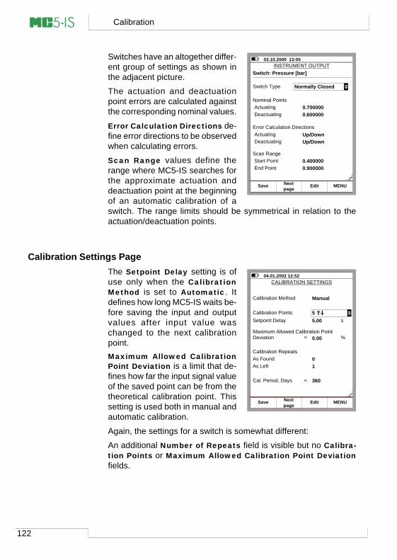
122
Calibration
Switches have an altogether differ-ent group of settings as shown inthe adjacent picture.
The actuation and deactuationpoint errors are calculated againstthe corresponding nominal values.
Error Calculation Directions de-fine error directions to be observedwhen calculating errors.
Scan Range values define therange where MC5-IS searches forthe approximate actuation anddeactuation point at the beginningof an automatic calibration of aswitch. The range limits should be symmetrical in relation to theactuation/deactuation points.
Calibration Settings PageThe Setpoint Delay setting is ofuse only when the CalibrationMethod is set to Automatic. Itdefines how long MC5-IS waits be-fore saving the input and outputvalues after input value waschanged to the next calibrationpoint.Maximum Allowed CalibrationPoint Deviation is a limit that de-fines how far the input signal valueof the saved point can be from thetheoretical calibration point. Thissetting is used both in manual andautomatic calibration.
Again, the settings for a switch is somewhat different:
An additional Number of Repeats field is visible but no Calibra-tion Points or Maximum Allowed Calibration Point Deviationfields.
03.10.2000 13:05INSTRUMENT OUTPUT
Switch Type
Switch: Pressure [bar]
Nominal PointsActuating 0.700000Deactuating 0.600000
Error Calculation DirectionsActuating Up/DownDeactuating Up/Down
Normally Closed
Scan RangeStart Point 0.400000End Point 0.900000
MENUSavepageNext Edit
04.01.2002 12:52CALIBRATION SETTINGS
Calibration Method Manual
As Found 0
Setpoint Delay 5.00
Maximum Allowed Calibration Point Deviation
Calibration Points 5
As Left 1
0.00<
s
%
MENUSavepageNext Edit
Cal. Period, Days 360<
Calibration Repeats
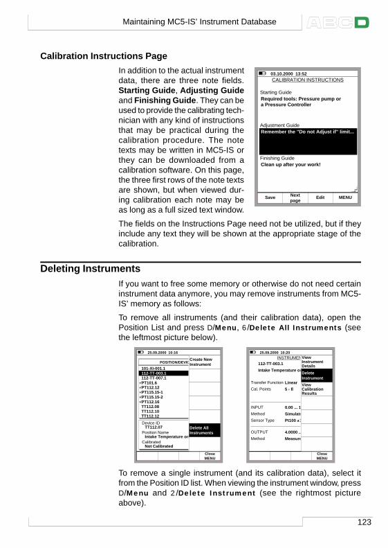
123
Calibration Instructions PageIn addition to the actual instrumentdata, there are three note fields.Starting Guide, Adjusting Guideand Finishing Guide. They can beused to provide the calibrating tech-nician with any kind of instructionsthat may be practical during thecalibration procedure. The notetexts may be written in MC5-IS orthey can be downloaded from acalibration software. On this page,the three first rows of the note textsare shown, but when viewed dur-ing calibration each note may beas long as a full sized text window.
The fields on the Instructions Page need not be utilized, but if theyinclude any text they will be shown at the appropriate stage of thecalibration.
Deleting InstrumentsIf you want to free some memory or otherwise do not need certaininstrument data anymore, you may remove instruments from MC5-IS’ memory as follows:
To remove all instruments (and their calibration data), open thePosition List and press D/Menu, 6/Delete All Instruments (seethe leftmost picture below).
To remove a single instrument (and its calibration data), select itfrom the Position ID list. When viewing the instrument window, pressD/Menu and 2/Delete Instrument (see the rightmost pictureabove).
03.10.2000 13:52CALIBRATION INSTRUCTIONS
Starting Guide
Adjustment Guide
Finishing Guide
Required tools: Pressure pump or a Pressure Controller
Remember the "Do not Adjust if" limit...
Clean up after your work!
MENUSavepageNext Edit
25.09.2000 10:16
POSITION/DEVICE ID101-XI-001.1112-TT-003.1112-TT-007.1PT101.6PT112.12PT115.15-1PT115.15-2PT112.16TT112.08TT112.10TT112.12Device ID
Position Name
Calibrated
TT112.07
Intake Temperature on Feed 1
Not Calibrated
ModeBasic MENUSelect
MENUClose
Create New Instrument
Delete AllInstruments
25.09.2000 10:20 INSTRUMENT
112-TT-003.1
Edit Calibrate MENU
Intake Temperature on Feed 1
Cal. Points 5 ↑↓
Transfer Function Linear
Method SimulatedINPUT 0.00 ... 100.00 °C
Sensor Type Pt100 α385
Method MeasuredOUTPUT 4.0000 ... 20.0000 mA
BackMENUClose
DeleteInstrument
ViewInstrumentDetails
ViewCalibrationResults
Maintaining MC5-IS’ Instrument Database
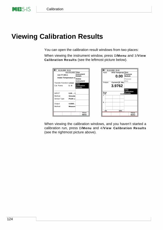
124
Calibration
Viewing Calibration Results
You can open the calibration result windows from two places:
When viewing the instrument window, press D/Menu and 3/ViewCalibration Results (see the leftmost picture below).
When viewing the calibration windows, and you haven’t started acalibration run, press D/Menu and 4/View Calibration Results(see the rightmost picture above).
03.10.2000 15:21 INSTRUMENT
112-TT-003.1
Edit Calibrate MENU
Intake Temperature on Feed 1
Cal. Points 5 ↑↓
Transfer Function Linear
Method SimulatedINPUT 0.00 ... 100.00 °C
Sensor Type Pt100 α385
Method MeasuredOutput 4.0000 ... 20.0000 mA
BackMENUClose
DeleteInstrument
ViewInstrumentDetails
ViewCalibrationResults
03.10.2000 15:22 Input
Error1.00
Output
Pt100 α385°C (ITS90)
3.9762
-0.15 % of span
0.00
+
0
-0% 50% 100%
RTD Temperature [ET: Simul]
Current [E: Meas]
mA
Start MENU Back Adjust
Prescan[On]
ZeroPressureModule
View Calibration Results
MENUClose
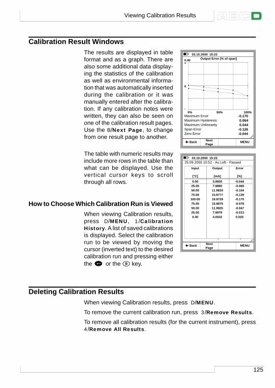
125
Calibration Result WindowsThe results are displayed in tableformat and as a graph. There arealso some additional data display-ing the statistics of the calibrationas well as environmental informa-tion that was automatically insertedduring the calibration or it wasmanually entered after the calibra-tion. If any calibration notes werewritten, they can also be seen onone of the calibration result pages.Use the B/Next Page, to changefrom one result page to another.
The table with numeric results mayinclude more rows in the table thanwhat can be displayed. Use thevertical cursor keys to scrollthrough all rows.
How to Choose Which Calibration Run is ViewedWhen viewing Calibration results,press D/MENU, 1/CalibrationHistory. A list of saved calibrationsis displayed. Select the calibrationrun to be viewed by moving thecursor (inverted text) to the desiredcalibration run and pressing eitherthe
or the key..
Deleting Calibration ResultsWhen viewing Calibration results, press D/MENU.
To remove the current calibration run, press 3/Remove Results.
To remove all calibration results (for the current instrument), press4/Remove All Results.
03.10.2000 15:22
PageNext MENU Back
0.40 Output Error [% of span]+
0
-0% 50% 100%
Maximum ErrorMaximum HysteresisMaximum UnlinearitySpan Error
-0.1700.0640.044
-0.126Zero Error -0.044
03.10.2000 15:22
BackPageNext MENU
25.09.2000 10:52 - As Left - PassedInput
[°C]0.0025.0050.0075.00100.0075.0050.0025.000.00
Output
[mA]3.99307.989011.983415.977719.972915.987511.99257.99794.0032
Error
[%]-0.044-0.069-0.104-0.139-0.170-0.078-0.047-0.0130.020
1 2
Viewing Calibration Results
126
Calibration
(Empty)
Appendixes
Appendix 1:User Guide forMC5 HART Option ................. 128Appendix 2:Technical Data ....................... 142Appendix 3:Quick Guide forthe MC5 Datalog Viewer ........ 148Appendix 4:Index ....................................... 152
128
Appendix 1, User Guide for MC5 HART Option
Appendix 1, User Guide forMC5-IS HART Option
ContentsGeneral 129MC5-IS and HART ............................ 129HART Instruments and Beamex'sCalibration Database Software .......... 130
Connecting MC5-IS and a HARTInstrument 130
External Supply ................................. 130Test Diode Connections .................... 131Using MC5-IS asa Hart Communicator ........................ 131
HART Communication Settings 132
HART and MC5-IS’ Basic Mode 133Connecting to a HART Instrument .... 133
Disconnecting aHART Instrument ......................... 134Device Information ....................... 134Device Settings ............................ 135Trimming a HART Instrumentin Basic Mode .............................. 135Adding a HART Instrument toMC5-IS’ Instrument Database ..... 137
Calibrating a HART Instrument 138Selecting the Instrumentto be Calibrated ................................. 138The Calibration Procedure ................ 139
Trimming a HART Instrumentin Calibration Mode ...................... 139
129
General
HART (Highway Addressable Remote Transducer) is a digital com-munication protocol that uses sine waves superimposed on the stan-dard 4 - 20 mA current. Because the HART signal is small, and itsaverage value is zero it does not affect the accuracy of the analogcurrent signal.
HART is a master-slave communication protocol, which means thatduring normal operation, each slave (field device) communicationis initiated by a master communication device. Two masters (a pri-mary master and a secondary master) can connect to each HARTloop.
The HART communication protocol is an open standard owned bythe member companies in the HART Communication Foundation(HCF). For additional information contact:HART Communication Foundation,9390 Research Boulevard, Suite I-350, Austin, Texas, 8759 USA.Internet: http://www.hartcomm.org
MC5-IS and HARTMC5-IS Multifunction Calibrator’s HART communication is a firm-ware option that can be used provided an E module is included inthe MC5-IS at hand. The HART modem required for HART commu-nication is located in the E module and the terminals of the E mod-ule are used for connecting MC5-IS with the Hart instrument.
MC5-IS supports HART Revision 5. Earlier revisions are not sup-ported.
MC5-IS treats the Analog Output (AO) and the Digital Output (PV,Primary Variable) as separate instruments. To calibrate/trim bothoutput signals, an Analog Output instrument and a Digital Outputinstrument need to be created into MC5-IS’ instrument database.This can be done manually or automatically by communicating withthe HART instrument to be calibrated/trimmed.
General
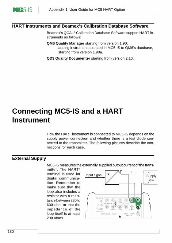
130
Appendix 1, User Guide for MC5 HART Option
HART Instruments and Beamex’s Calibration Database SoftwareBeamex’s QCAL® Calibration Database Software support HART in-struments as follows:
QM6 Quality Manager starting from version 1.90.adding instruments created in MC5-IS to QM6’s database,starting from version 1.90a.
QD3 Quality Documenter starting from version 2.10.
Connecting MC5-IS and a HARTInstrument
How the HART instrument is connected to MC5-IS depends on thesupply power connection and whether there is a test diode con-nected to the transmitter. The following pictures describe the con-nections for each case.
External SupplyMC5-IS measures the externally supplied output current of the trans-mitter. The HART®
terminal is used fordigital communica-tion. Remember tomake sure that theloop also includes aresistor with a resis-tance between 230 to600 ohm or that theimpedance of theloop itself is at least230 ohms.
T/C, Low V HART® Imeas/sink
V, ,
V, I , sink
Com
R, RTD
Low V
MEASUREOUTPUT
ET E
T/C INT. RJ
SENSOR MEASURE & SIMULATE
Uo: 16 V Io: 24 mA
Po: 145 mW
T/C WIRES ONLY
4 w meas
3 w measmeas/sim
+
I
Input signal X
HART® Imeas/sink
Com
Supplyetc.
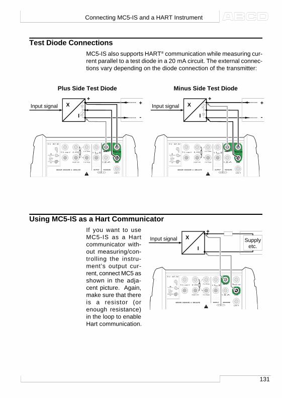
131
Test Diode ConnectionsMC5-IS also supports HART® communication while measuring cur-rent parallel to a test diode in a 20 mA circuit. The external connec-tions vary depending on the diode connection of the transmitter:
Plus Side Test Diode Minus Side Test Diode
Using MC5-IS as a Hart CommunicatorIf you want to useMC5-IS as a Hartcommunicator with-out measuring/con-trolling the instru-ment’s output cur-rent, connect MC5 asshown in the adja-cent picture. Again,make sure that thereis a resistor (orenough resistance)in the loop to enableHart communication.
T/C, Low V HART® Imeas/sink
V, ,
V, I , sink
Com
R, RTD
Low V
MEASUREOUTPUT
ET E
T/C INT. RJ
SENSOR MEASURE & SIMULATE
Uo: 16 V Io: 24 mA
Po: 145 mW
T/C WIRES ONLY
4 w meas
3 w measmeas/sim
+
I
Input signal X
HART® Imeas/sink
Com*
*
*
*HART® Imeas/sink
Com
+
-
T/C, Low V HART® Imeas/sink
V, ,
V, I , sink
Com
R, RTD
Low V
MEASUREOUTPUT
ET E
T/C INT. RJ
SENSOR MEASURE & SIMULATE
Uo: 16 V Io: 24 mA
Po: 145 mW
T/C WIRES ONLY
4 w meas
3 w measmeas/sim
+
I
Input signal X
HART® Imeas/sink
Com*
*
*
*HART® Imeas/sink
Com
+
-
T/C, Low V HART® Imeas/sink
V, ,
V, I , sink
Com
R, RTD
Low V
MEASUREOUTPUT
ET E
T/C INT. RJ
SENSOR MEASURE & SIMULATE
Uo: 16 V Io: 24 mA
Po: 145 mW
T/C WIRES ONLY
4 w meas
3 w measmeas/sim
+
I
Input signal X Supplyetc.
HART®
Com
Connecting MC5-IS and a HART Instrument
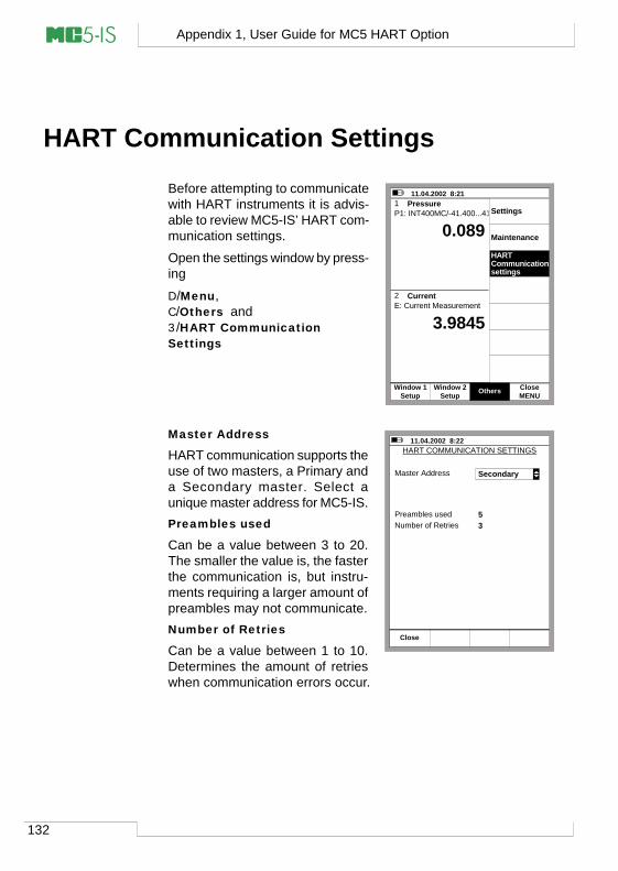
132
Appendix 1, User Guide for MC5 HART Option
HART Communication Settings
Before attempting to communicatewith HART instruments it is advis-able to review MC5-IS’ HART com-munication settings.
Open the settings window by press-ing
D/Menu,C/Others and3/HART CommunicationSettings
Master Address
HART communication supports theuse of two masters, a Primary anda Secondary master. Select aunique master address for MC5-IS.Preambles used
Can be a value between 3 to 20.The smaller the value is, the fasterthe communication is, but instru-ments requiring a larger amount ofpreambles may not communicate.Number of Retries
Can be a value between 1 to 10.Determines the amount of retrieswhen communication errors occur.
11.04.2002 8:21 1 Pressure
2 Current
P1: INT400MC/-41.400...41.400 kPa
E: Current Measurement
gaugekPa0.089
3.9845 mA
Settings
Maintenance
HARTCommunicationsettings
OthersMENUClose
SetupWindow 1
SetupWindow 2
11.04.2002 8:22 HART COMMUNICATION SETTINGS
Master Address
Preambles usedNumber of Retries
53
Close
Secondary
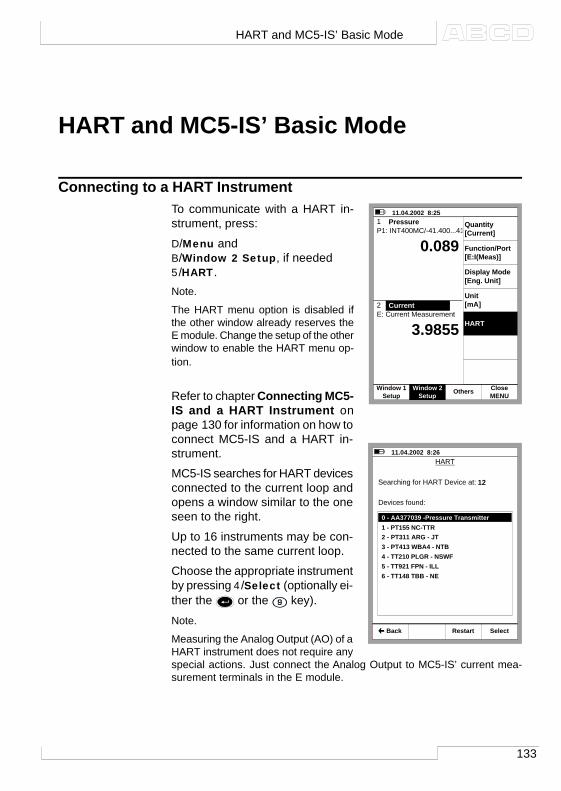
133
HART and MC5-IS’ Basic Mode
Connecting to a HART InstrumentTo communicate with a HART in-strument, press:
D/Menu andB/Window 2 Setup, if needed5/HART.Note.
The HART menu option is disabled ifthe other window already reserves theE module. Change the setup of the otherwindow to enable the HART menu op-tion.
Refer to chapter Connecting MC5-IS and a HART Instrument onpage 130 for information on how toconnect MC5-IS and a HART in-strument.
MC5-IS searches for HART devicesconnected to the current loop andopens a window similar to the oneseen to the right.
Up to 16 instruments may be con-nected to the same current loop.
Choose the appropriate instrumentby pressing 4/Select (optionally ei-ther the or the key).
Note.
Measuring the Analog Output (AO) of aHART instrument does not require anyspecial actions. Just connect the Analog Output to MC5-IS’ current mea-surement terminals in the E module.
11.04.2002 8:26
0 - AA377039 -Pressure Transmitter1 - PT155 NC-TTR2 - PT311 ARG - JT3 - PT413 WBA4 - NTB4 - TT210 PLGR - NSWF 5 - TT921 FPN - ILL6 - TT148 TBB - NE
Select Back
HART
Searching for HART Device at:
Devices found:
12
Restart
11.04.2002 8:25 1 PressureP1: INT400MC/-41.400...41.400 kPa
E: Current Measurement
gaugekPa0.089
3.9855 mA
2 Current
Quantity[Current]
Function/Port[E:I(Meas)]
Unit[mA]
HART
SetupWindow 2
MENUClose
SetupWindow 1 Others
Display Mode[Eng. Unit]
HART and MC5-IS’ Basic Mode
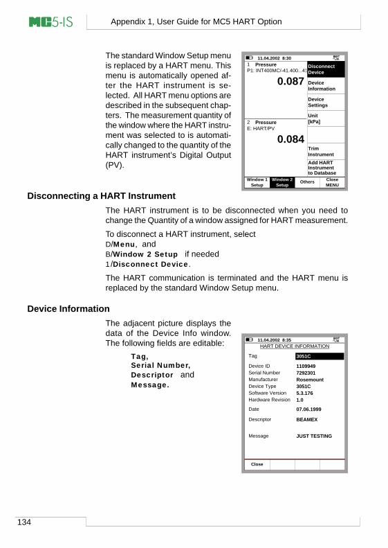
134
Appendix 1, User Guide for MC5 HART Option
The standard Window Setup menuis replaced by a HART menu. Thismenu is automatically opened af-ter the HART instrument is se-lected. All HART menu options aredescribed in the subsequent chap-ters. The measurement quantity ofthe window where the HART instru-ment was selected to is automati-cally changed to the quantity of theHART instrument’s Digital Output(PV).
Disconnecting a HART InstrumentThe HART instrument is to be disconnected when you need tochange the Quantity of a window assigned for HART measurement.
To disconnect a HART instrument, selectD/Menu, andB/Window 2 Setup if needed1/Disconnect Device.
The HART communication is terminated and the HART menu isreplaced by the standard Window Setup menu.
Device InformationThe adjacent picture displays thedata of the Device Info window.The following fields are editable:
Tag,Serial Number,Descriptor andMessage.
11.04.2002 8:301 PressureP1: INT400MC/-41.400...41.400 kPa
E: HART/PV
gaugekPa0.087
0.084 kPa
2 Pressure
Disconnect Device
Device Information
Device Settings
Unit[kPa]
Trim InstrumentAdd HARTInstrumentto Database
OthersMENUClose
SetupWindow 1
SetupWindow 2
11.04.2002 8:35HART DEVICE INFORMATION
Tag
Device ID
Date
1109949
07.06.1999
Close
3051C
Descriptor BEAMEX
Message JUST TESTING
Serial Number 7292301Manufacturer RosemountDevice Type 3051CSoftware Version 5.3.176Hardware Revision 1.0
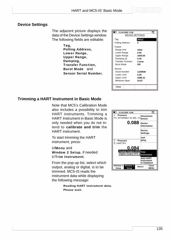
135
Device SettingsThe adjacent picture displays thedata of the Device Settings window.The following fields are editable:
Tag,Polling Address,Lower Range,Upper Range,Damping,Transfer Function,Burst Mode andSensor Serial Number.
Trimming a HART Instrument in Basic ModeNote that MC5’s Calibration Modealso includes a possibility to trimHART instruments. Trimming aHART Instrument in Basic Mode isonly needed when you do not in-tend to calibrate and trim theHART instrument.
To start trimming the HARTinstrument, press:
D/Menu andWindow 2 Setup, if needed6/Trim Instrument.
From the pop-up list, select whichoutput, analog or digital, is to betrimmed. MC5-IS reads theinstrument data while displayingthe following message:
Reading HART instrument data.Please wait.
11.04.2002 8:38 DEVICE SETTINGS
TagPolling Address 0
Close
3051C
OutputRange Unit mbarLower Range 0.00Upper Range 1000.00Damping (s) 0.40Transfer Function LinearBurst Mode Off
SensorSerial Number 1109949Lower Limit 0.00Upper Limit 2486.41Minimum Span 24.87
11.04.2002 8:491 PressureP1: INT400MC/-41.400...41.400 kPa
E: HART/PV
gaugekPa0.088
0.084 kPa
2 Pressure
Close
Disconnect Device
Device Information
Device Settings
Unit[kPa]
Trim InstrumentAdd HARTInstrumentto Database
Analog Output (AO)Digital Output (PV)
OthersMENUClose
SetupWindow 1
SetupWindow 2
HART and MC5-IS’ Basic Mode
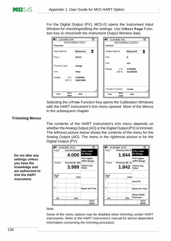
136
Appendix 1, User Guide for MC5 HART Option
For the Digital Output (PV), MC5-IS opens the Instrument InputWindow for checking/editing the settings. Use B/Next Page Func-tion Key to check/edit the Instrument Output Window data.
Do not alter anysettings unlessyou have theknowledge andare authorized totrim the HARTinstrument.
Note.
Some of the menu options may be disabled when trimming certain HARTinstruments. Refer to the HART instrument’s manual for device dependentinformation concerning the trimming procedure.
Selecting the A/Trim Function Key opens the Calibration Windowswith the HART instrument’s trim menu opened. More of the Menusin the subsequent chapter.
Trimming MenusThe contents of the HART instrument’s trim menu depends onwhether the Analog Output (AO) or the Digital Output (PV) is trimmed.The leftmost picture below shows the contents of the menu for theAnalog Output (AO). The menu in the rightmost picture is for theDigital Output (PV).
11.04.2002 8:50INSTRUMENT INPUT
Input Method Measured
Unit mbar
Range 0.000000
Pressure
Port 1 INT1C
Pressure type Gauge
0 %1000.0000100 %
TrimpageNext Edit
11.04.2002 8:51INSTRUMENT OUTPUT
Output Method
Range 4.000000
Current
Port E
Unit mA
0 %20.000000100 %
Transfer Function Linear
Measured
TrimpageNext Edit
21.05.2002 12:27 Input
Error1.00
Output
mA
3.999
-0.01 % alueesta
4.000
+
0
-0% 50% 100%
Current [Keyed]
Current [E: Meas.]
mA
kalibrointiHylkää
TallennaMENUClose
Trim Lower0% Range
Trim Upper100% Range
Check Any Value
Reset AO Trim
21.05.2002 13:15 Input
Error1.00
Output
kPa
1.842
-0.04 % alueesta
1.844
+
0
-0% 50% 100%
Pressure [P1:INT1C]
Pressure [E: HART]
kPa
kalibrointiHylkää
Tallenna
gauge
MENUClose
Trim Lower0% Range
Trim Upper100% Range
Reset StaticPressure
Check AnyValue
Zero PV
Reset PV Trim
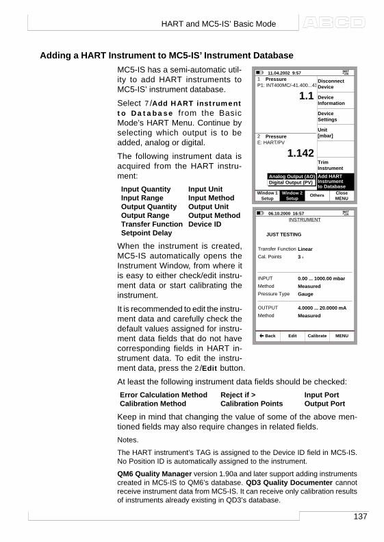
137
Adding a HART Instrument to MC5-IS’ Instrument DatabaseMC5-IS has a semi-automatic util-ity to add HART instruments toMC5-IS’ instrument database.
Select 7/Add HART instrumentto Database from the BasicMode’s HART Menu. Continue byselecting which output is to beadded, analog or digital.
The following instrument data isacquired from the HART instru-ment:Input Quantity Input UnitInput Range Input MethodOutput Quantity Output UnitOutput Range Output MethodTransfer Function Device IDSetpoint Delay
When the instrument is created,MC5-IS automatically opens theInstrument Window, from where itis easy to either check/edit instru-ment data or start calibrating theinstrument.
It is recommended to edit the instru-ment data and carefully check thedefault values assigned for instru-ment data fields that do not havecorresponding fields in HART in-strument data. To edit the instru-ment data, press the 2/Edit button.
At least the following instrument data fields should be checked:Error Calculation Method Reject if > Input PortCalibration Method Calibration Points Output Port
Keep in mind that changing the value of some of the above men-tioned fields may also require changes in related fields.Notes.
The HART instrument’s TAG is assigned to the Device ID field in MC5-IS.No Position ID is automatically assigned to the instrument.
QM6 Quality Manager version 1.90a and later support adding instrumentscreated in MC5-IS to QM6’s database. QD3 Quality Documenter cannotreceive instrument data from MC5-IS. It can receive only calibration resultsof instruments already existing in QD3’s database.
11.04.2002 9:571 PressureP1: INT400MC/-41.400...41.400 kPa
E: HART/PV
gaugekPa1.1
1.142 kPa
2 Pressure
Disconnect Device
Device Information
Device Settings
Unit[mbar]
Trim InstrumentAdd HARTInstrumentto Database
Analog Output (AO)Digital Output (PV)
SetupWindow 2
MENUClose
SetupWindow 1 Others
06.10.2000 16:57 INSTRUMENT
112-TT-003.1
Edit Calibrate MENU
JUST TESTING
Cal. Points 3 ↑Transfer Function Linear
Method MeasuredINPUT 0.00 ... 1000.00 mbar
Pressure Type Gauge
Method MeasuredOUTPUT 4.0000 ... 20.0000 mA
Back
HART and MC5-IS’ Basic Mode
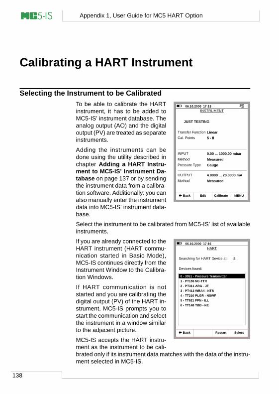
138
Appendix 1, User Guide for MC5 HART Option
Calibrating a HART Instrument
Selecting the Instrument to be CalibratedTo be able to calibrate the HARTinstrument, it has to be added toMC5-IS’ instrument database. Theanalog output (AO) and the digitaloutput (PV) are treated as separateinstruments.
Adding the instruments can bedone using the utility described inchapter Adding a HART Instru-ment to MC5-IS’ Instrument Da-tabase on page 137 or by sendingthe instrument data from a calibra-tion software. Additionally: you canalso manually enter the instrumentdata into MC5-IS’ instrument data-base.
Select the instrument to be calibrated from MC5-IS’ list of availableinstruments.
If you are already connected to theHART instrument (HART commu-nication started in Basic Mode),MC5-IS continues directly from theInstrument Window to the Calibra-tion Windows.
If HART communication is notstarted and you are calibrating thedigital output (PV) of the HART in-strument, MC5-IS prompts you tostart the communication and selectthe instrument in a window similarto the adjacent picture.
MC5-IS accepts the HART instru-ment as the instrument to be cali-brated only if its instrument data matches with the data of the instru-ment selected in MC5-IS.
06.10.2000 17:13 INSTRUMENT
112-TT-003.1
Edit Calibrate MENU
JUST TESTING
Transfer Function Linear
Method MeasuredINPUT 0.00 ... 1000.00 mbar
Pressure Type Gauge
Method MeasuredOUTPUT 4.0000 ... 20.0000 mA
Back
Cal. Points 5 ↑↓
06.10.2000 17:16
0 - 3051 - Pressure Transmitter1 - PT155 NC-TTR2 - PT311 ARG - JT3 - PT413 WBA4 - NTB4 - TT210 PLGR - NSWF 5 - TT921 FPN - ILL6 - TT148 TBB - NE
Select Back
HART
Searching for HART Device at: 8
Devices found:
Restart
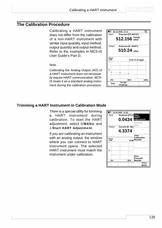
139
The Calibration ProcedureCalibrating a HART instrumentdoes not differ from the calibrationof a non-HART instrument withsimilar input quantity, input method,output quantity and output method.Refer to the examples in MC5-ISUser Guide’s Part D.
Note.
Calibrating the Analog Output (AO) ofa HART instrument does not necessar-ily require HART communication. MC5-IS treats it as a standard analog instru-ment during the calibration procedure.
Trimming a HART Instrument in Calibration ModeThere is a special utility for trimminga HART instrument duringcalibration. To start the HARTadjustment, select D/MENU and1/Start HART Adjustment.
If you are calibrating an instrumentwith an analog output, the windowwhere you can connect to HARTinstrument opens. The selectedHART instrument must match theinstrument under calibration.
06.10.2000 17:21 Input
Error1.00
Output
mbar
510.24
-0.21 % of span
512.156
+
0
-0% 50% 100%
Pressure [P1:INT1C]
Pressure [E: HART]
mbar
Gauge
StopReadings
Accept
15.05.2002 13:22 Input
Error1.00
Output
kPa
4.3374
-0.06 % of span
0.0434
+
0
-0% 50% 100%
Pressure [P1:INT20C]
Current [E: Meas]
mA
gauge
MENUClose
Prescan[On]
Start HARTAdjustment
ViewCalibrationResults
ZeroPressureModule
Calibrating a HART Instrument
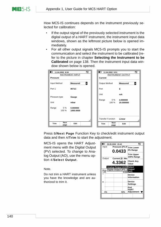
140
Appendix 1, User Guide for MC5 HART Option
How MC5-IS continues depends on the instrument previously se-lected for calibration:
• If the output signal of the previously selected instrument is thedigital output of a HART instrument, the instrument input datawindows, shown as the leftmost picture below is opened im-mediately.
• For all other output signals MC5-IS prompts you to start thecommunication and select the instrument to be calibrated (re-fer to the picture in chapter Selecting the Instrument to beCalibrated on page 138. Then the instrument input data win-dow shown below is opened.
11.04.2002 8:50INSTRUMENT INPUT
Input Method Measured
Unit mbar
Range 0.000000
Pressure
Port 1 INT1C
Pressure type Gauge
0 %1000.0000100 %
TrimpageNext Edit
11.04.2002 8:51INSTRUMENT OUTPUT
Output Method
Range 4.000000
Current
Port E
Unit mA
0 %20.000000100 %
Transfer Function Linear
Measured
TrimpageNext Edit
Press B/Next Page Function Key to check/edit instrument outputdata and then A/Trim to start the adjustment.
MC5-IS opens the HART Adjust-ment menu with the Digital Output(PV) selected. To change to Ana-log Output (AO), use the menu op-tion 4/Select Output.
Note.
Do not trim a HART instrument unlessyou have the knowledge and are au-thorized to trim it.
29.05.2002 15:42 Input
Error1.00
Output
kPa
4.3362
-0.04 % of span
0.0433
+
0
-0% 50% 100%
Pressure [P1:INT20C]
Current [E: Meas]
mA
gaugeTrim Lower0% Range
Trim Upper100% Range
Check Any Value
DeviceInformation
Device Settings
SelectOutput[AO]
End HARTAdjustment
Analog Output (AO)Digital Output (PV)

141
When trimming the Digital Output(PV), the Input window displaysthe instrument’s input signal mea-sured by MC5-IS. The Output win-dow displays the digital output ofthe instrument.
The lower part of the Output win-dow includes an additional trimfield. Use either the C/Fetch Func-tion Key to copy the value shownin the input window or manuallyenter a value the digital outputshould be trimmed to. Then usethe D/Send Function Key.
When trimming the Analog Output(AO), the Input window displaysthe current set point communicatedby MC5-IS. The Output windowdisplays the current generated bythe instrument and measured byMC5-IS.
Again, the lower part of the Out-put window includes an additionalfield. Use either the C/Fetch Func-tion Key to copy the value shownin the Output window or manuallyenter a value that is the correctoutput current. Then use theD/Send Function Key.
Note.
Some of the menu options may be disabled when trimming certain HARTinstruments. Refer to the HART instrument’s manual for device dependentinformation concerning the trimming procedure.
16.05.2002 15:58Input
Error1.00
Output
bar
1.021
-0.04 % of span
1.029
+
0
-0% 50% 100%
Pressure [P1:INT20C]
Pressure [E: HART \ PV]
bar
Trim 0% to:
TrimEnd Fetch MENU
Gauge
1.029
Calibrating a HART Instrument
20.08.2002 15:44 Input
Error1.00
Output
mA
3.9982
N/A % of span
4.0000
+
0
-0% 50% 100%
Current [Keyed]
Current [E: Meas.]
mA
Enter measured 0%
TrimEnd Fetch MENU
3.9982
142
Appendix 2, Technical Data
Appendix 2,Technical Data
ContentsMC5-IS General Specifications 143
Modules 144Pressure Modules(INT-IS & EXT-IS) ................................ 144Temperature ElectricalModule (ET) ....................................... 145
RTD Measurementand Simulation ............................. 145Thermocouple Measurementand Simulation ............................. 146Reference JunctionModule (RJ) .................................. 146
Electrical Module (E) ......................... 147
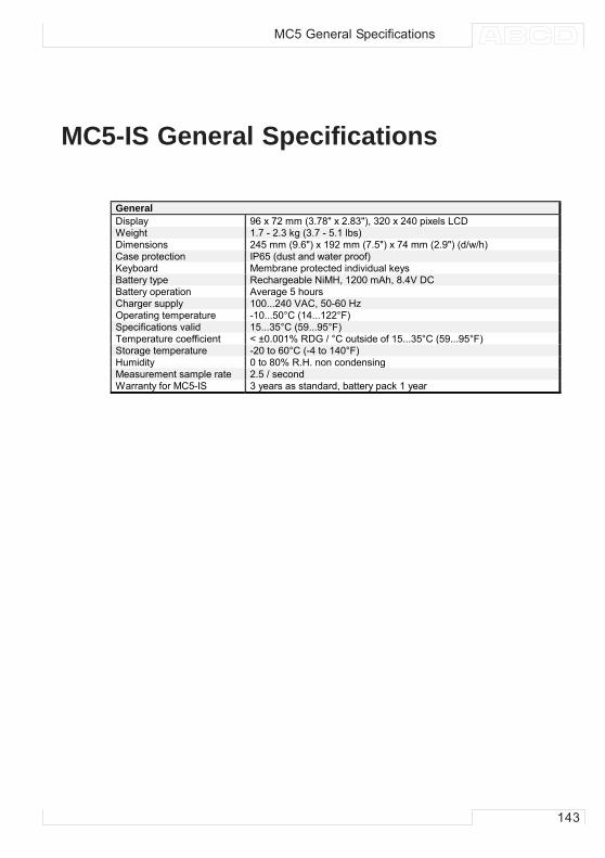
143
MC5-IS General Specifications
MC5 General Specifications
GeneralDisplay 96 x 72 mm (3.78" x 2.83"), 320 x 240 pixels LCDWeight 1.7 - 2.3 kg (3.7 - 5.1 lbs)Dimensions 245 mm (9.6") x 192 mm (7.5") x 74 mm (2.9") (d/w/h)Case protection IP65 (dust and water proof)Keyboard Membrane protected individual keysBattery type Rechargeable NiMH, 1200 mAh, 8.4V DCBattery operation Average 5 hoursCharger supply 100...240 VAC, 50-60 HzOperating temperature -10...50°C (14...122°F)Specifications valid 15...35°C (59...95°F)Temperature coefficient < ±0.001% RDG / °C outside of 15...35°C (59...95°F)Storage temperature -20 to 60°C (-4 to 140°F)Humidity 0 to 80% R.H. non condensingMeasurement sample rate 2.5 / secondWarranty for MC5-IS 3 years as standard, battery pack 1 year
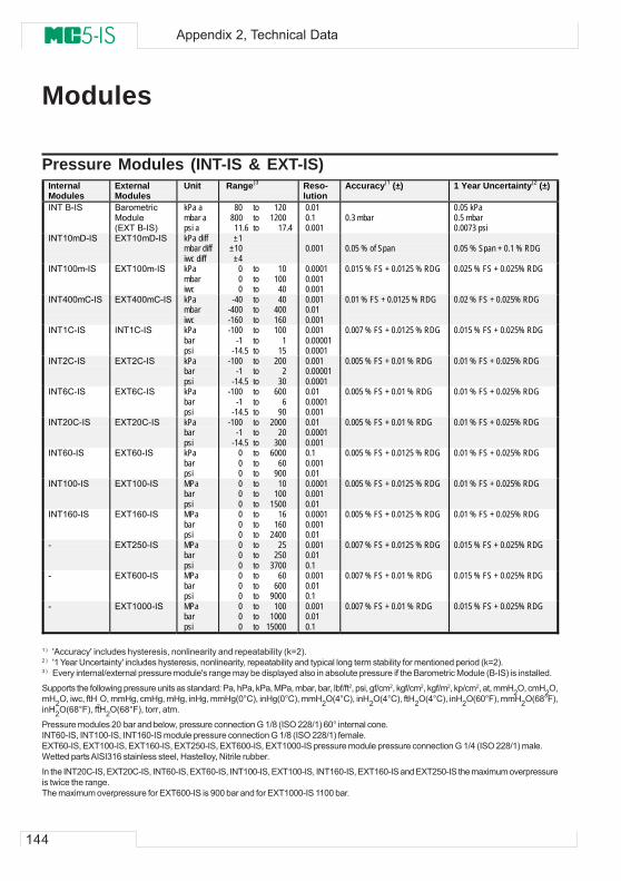
144
Appendix 2, Technical Data
Modules
Pressure Modules (INT-IS & EXT-IS)
1 ) 'Accuracy' includes hysteresis, nonlinearity and repeatability (k=2).2 ) '1 Year Uncertainty' includes hysteresis, nonlinearity, repeatability and typical long term stability for mentioned period (k=2).3 ) Every internal/external pressure module's range may be displayed also in absolute pressure if the Barometric Module (B-IS) is installed.
Supports the following pressure units as standard: Pa, hPa, kPa, MPa, mbar, bar, lbf/ft2, psi, gf/cm2, kgf/cm2, kgf/m2, kp/cm2, at, mmH2O, cmH2O,mH2O, iwc, ftH
2O, mmHg, cmHg, mHg, inHg, mmHg(0°C), inHg(0°C), mmH2O(4°C), inH2O(4°C), ftH2O(4°C), inH2O(60°F), mmH2O(68°F),
inH2O(68°F), ftH2O(68°F), torr, atm.
Pressure modules 20 bar and below, pressure connection G 1/8 (ISO 228/1) 60° internal cone.INT60-IS, INT100-IS, INT160-IS module pressure connection G 1/8 (ISO 228/1) female.EXT60-IS, EXT100-IS, EXT160-IS, EXT250-IS, EXT600-IS, EXT1000-IS pressure module pressure connection G 1/4 (ISO 228/1) male.Wetted parts AISI316 stainless steel, Hastelloy, Nitrile rubber.
In the INT20C-IS, EXT20C-IS, INT60-IS, EXT60-IS, INT100-IS, EXT100-IS, INT160-IS, EXT160-IS and EXT250-IS the maximum overpressureis twice the range.The maximum overpressure for EXT600-IS is 900 bar and for EXT1000-IS 1100 bar.
Internal Modules
External Modules
Unit Range(3 Reso-lution
Accuracy(1 (±) 1 Year Uncertainty(2 (±)
INT B-IS Barometric Module (EXT B-IS)
kPa a mbar a psi a
80 to 120 800 to 1200 11.6 to 17.4
0.01 0.1 0.001
0.3 mbar
0.05 kPa 0.5 mbar 0.0073 psi
INT10mD-IS
EXT10mD-IS kPa diff mbar diff iwc diff
±1 ±10 ±4
0.001
0.05 % of Span
0.05 % Span + 0.1 % RDG
INT100m-IS
EXT100m-IS
kPa mbar iwc
0 to 10 0 to 100 0 to 40
0.0001 0.001 0.001
0.015 % FS + 0.0125 % RDG
0.025 % FS + 0.025% RDG
INT400mC-IS
EXT400mC-IS
kPa mbar iwc
-40 to 40 -400 to 400 -160 to 160
0.001 0.01 0.001
0.01 % FS + 0.0125 % RDG
0.02 % FS + 0.025% RDG
INT1C-IS
INT1C-IS
kPa bar psi
-100 to 100 -1 to 1 -14.5 to 15
0.001 0.00001 0.0001
0.007 % FS + 0.0125 % RDG
0.015 % FS + 0.025% RDG
INT2C-IS
EXT2C-IS
kPa bar psi
-100 to 200 -1 to 2 -14.5 to 30
0.001 0.00001 0.0001
0.005 % FS + 0.01 % RDG
0.01 % FS + 0.025% RDG
INT6C-IS
EXT6C-IS
kPa bar psi
-100 to 600 -1 to 6 -14.5 to 90
0.01 0.0001 0.001
0.005 % FS + 0.01 % RDG
0.01 % FS + 0.025% RDG
INT20C-IS
EXT20C-IS kPa bar psi
-100 to 2000 -1 to 20 -14.5 to 300
0.01 0.0001 0.001
0.005 % FS + 0.01 % RDG
0.01 % FS + 0.025% RDG
INT60-IS
EXT60-IS
kPa bar psi
0 to 6000 0 to 60 0 to 900
0.1 0.001 0.01
0.005 % FS + 0.0125 % RDG
0.01 % FS + 0.025% RDG
INT100-IS
EXT100-IS
MPa bar psi
0 to 10 0 to 100 0 to 1500
0.0001 0.001 0.01
0.005 % FS + 0.0125 % RDG
0.01 % FS + 0.025% RDG
INT160-IS
EXT160-IS
MPa bar psi
0 to 16 0 to 160 0 to 2400
0.0001 0.001 0.01
0.005 % FS + 0.0125 % RDG
0.01 % FS + 0.025% RDG
-
EXT250-IS
MPa bar psi
0 to 25 0 to 250 0 to 3700
0.001 0.01 0.1
0.007 % FS + 0.0125 % RDG
0.015 % FS + 0.025% RDG
-
EXT600-IS
MPa bar psi
0 to 60 0 to 600 0 to 9000
0.001 0.01 0.1
0.007 % FS + 0.01 % RDG
0.015 % FS + 0.025% RDG
-
EXT1000-IS
MPa bar psi
0 to 100 0 to 1000 0 to 15000
0.001 0.01 0.1
0.007 % FS + 0.01 % RDG
0.015 % FS + 0.025% RDG
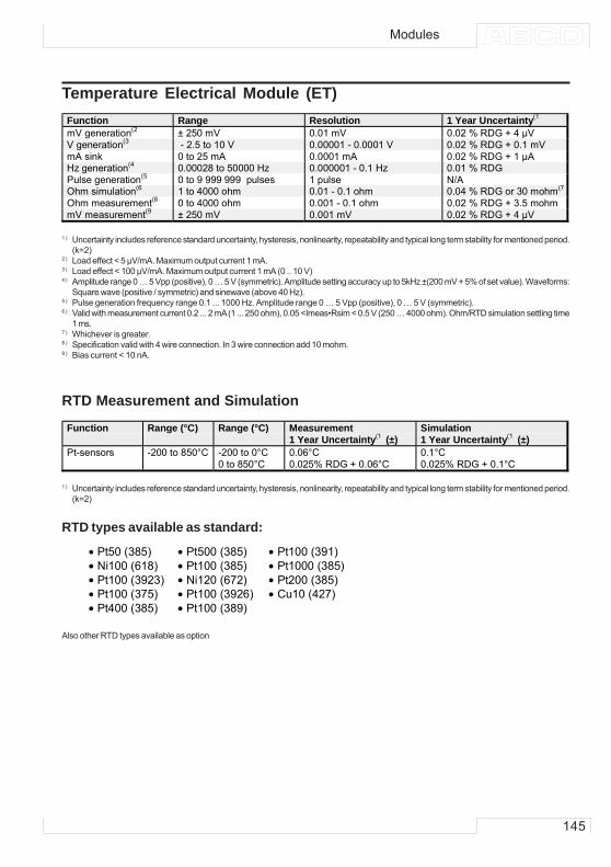
145
Temperature Electrical Module (ET)
1 ) Uncertainty includes reference standard uncertainty, hysteresis, nonlinearity, repeatability and typical long term stability for mentioned period.(k=2)
2 ) Load effect < 5 μV/mA. Maximum output current 1 mA.3 ) Load effect < 100 μV/mA. Maximum output current 1 mA (0 .. 10 V)4 ) Amplitude range 0 … 5 Vpp (positive), 0 … 5 V (symmetric). Amplitude setting accuracy up to 5kHz ±(200 mV + 5% of set value). Waveforms:
Square wave (positive / symmetric) and sinewave (above 40 Hz).5 ) Pulse generation frequency range 0.1 ... 1000 Hz. Amplitude range 0 … 5 Vpp (positive), 0 … 5 V (symmetric).6 ) Valid with measurement current 0.2 ... 2 mA (1 ... 250 ohm), 0.05 <Imeas•Rsim < 0.5 V (250 … 4000 ohm). Ohm/RTD simulation settling time
1 ms.7 ) Whichever is greater.8 ) Specification valid with 4 wire connection. In 3 wire connection add 10 mohm.9 ) Bias current < 10 nA.
RTD Measurement and Simulation
1 ) Uncertainty includes reference standard uncertainty, hysteresis, nonlinearity, repeatability and typical long term stability for mentioned period.(k=2)
RTD types available as standard:
Also other RTD types available as option
• Pt50 (385) • Pt500 (385) • Pt100 (391)• Ni100 (618) • Pt100 (385) • Pt1000 (385)• Pt100 (3923) • Ni120 (672) • Pt200 (385)• Pt100 (375) • Pt100 (3926) • Cu10 (427)• Pt400 (385) • Pt100 (389)
Modules
Function Range (°C) Range (°C) Measurement 1 Year Uncertainty(1 (±)
Simulation 1 Year Uncertainty(1 (±)
Pt-sensors -200 to 850°C -200 to 0°C 0.06°C 0.1°C 0 to 850°C 0.025% RDG + 0.06°C 0.025% RDG + 0.1°C
Function Range Resolution 1 Year Uncertainty(1
mV generation(2 ± 250 mV 0.01 mV 0.02 % RDG + 4 µV V generation(3 - 2.5 to 10 V 0.00001 - 0.0001 V 0.02 % RDG + 0.1 mV mA sink 0 to 25 mA 0.0001 mA 0.02 % RDG + 1 µA Hz generation(4 0.00028 to 50000 Hz 0.000001 - 0.1 Hz 0.01 % RDG Pulse generation(5 0 to 9 999 999 pulses 1 pulse N/A Ohm simulation(6 1 to 4000 ohm 0.01 - 0.1 ohm 0.04 % RDG or 30 mohm(7
Ohm measurement(8 0 to 4000 ohm 0.001 - 0.1 ohm 0.02 % RDG + 3.5 mohm mV measurement(9 ± 250 mV 0.001 mV 0.02 % RDG + 4 µV
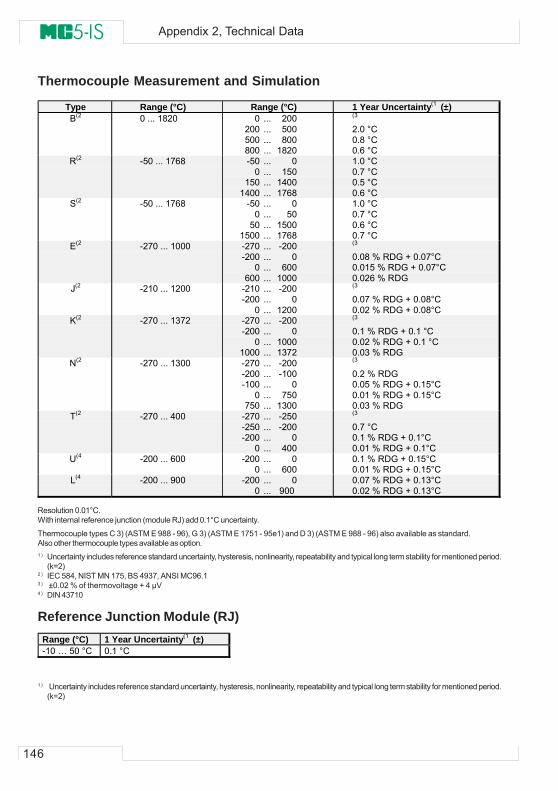
146
Appendix 2, Technical Data
Thermocouple Measurement and Simulation
Resolution 0.01°C.With internal reference junction (module RJ) add 0.1°C uncertainty.
Thermocouple types C 3) (ASTM E 988 - 96), G 3) (ASTM E 1751 - 95e1) and D 3) (ASTM E 988 - 96) also available as standard.Also other thermocouple types available as option.1 ) Uncertainty includes reference standard uncertainty, hysteresis, nonlinearity, repeatability and typical long term stability for mentioned period.
(k=2)2 ) IEC 584, NIST MN 175, BS 4937, ANSI MC96.13 ) ±0.02 % of thermovoltage + 4 µV4 ) DIN 43710
Reference Junction Module (RJ)
1 ) Uncertainty includes reference standard uncertainty, hysteresis, nonlinearity, repeatability and typical long term stability for mentioned period.(k=2)
Range (°C) 1 Year Uncertainty(1 (±) -10 … 50 °C 0.1 °C
Type Range (°C) Range (°C) 1 Year Uncertainty(1 (±) B(2 0 ... 1820 0 ... 200
200 ... 500 500 ... 800 800 ... 1820
(3 2.0 °C 0.8 °C 0.6 °C
R(2 -50 ... 1768 -50 ... 0 0 ... 150 150 ... 1400 1400 ... 1768
1.0 °C 0.7 °C 0.5 °C 0.6 °C
S(2 -50 ... 1768 -50 ... 0 0 ... 50 50 ... 1500 1500 ... 1768
1.0 °C 0.7 °C 0.6 °C 0.7 °C
E(2 -270 ... 1000 -270 ... -200 -200 ... 0 0 ... 600 600 ... 1000
(3
0.08 % RDG + 0.07°C 0.015 % RDG + 0.07°C 0.026 % RDG
J(2 -210 ... 1200 -210 ... -200 -200 ... 0 0 ... 1200
(3 0.07 % RDG + 0.08°C 0.02 % RDG + 0.08°C
K(2 -270 ... 1372 -270 ... -200 -200 ... 0 0 ... 1000 1000 ... 1372
(3 0.1 % RDG + 0.1 °C 0.02 % RDG + 0.1 °C 0.03 % RDG
N(2 -270 ... 1300 -270 ... -200 -200 ... -100 -100 ... 0 0 ... 750 750 ... 1300
(3
0.2 % RDG 0.05 % RDG + 0.15°C 0.01 % RDG + 0.15°C 0.03 % RDG
T(2 -270 ... 400 -270 ... -250 -250 ... -200 -200 ... 0 0 ... 400
(3
0.7 °C 0.1 % RDG + 0.1°C 0.01 % RDG + 0.1°C
U(4 -200 ... 600 -200 ... 0 0 ... 600
0.1 % RDG + 0.15°C 0.01 % RDG + 0.15°C
L(4 -200 ... 900 -200 ... 0 0 ... 900
0.07 % RDG + 0.13°C 0.02 % RDG + 0.13°C
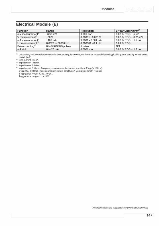
147
Electrical Module (E)
1 ) Uncertainty includes reference standard uncertainty, hysteresis, nonlinearity, repeatability and typical long term stability for mentionedperiod. (k=2)
2 ) Bias current <10 nA3 ) Impedance >1 Mohm4 ) Impedance < 7.5 ohm5 ) Impedance > 1 Mohm. Frequency measurement minimum amplitude 1 Vpp (< 10 kHz),
3 Vpp (10...50 kHz). Pulse counting minimum amplitude 1 Vpp (pulse length > 50 µs),3 Vpp (pulse length 50 µs...10 µs).Trigger level range -1…+15 V.
All specifications are subject to change without prior notice
Modules
Function Range Resolution 1 Year Uncertainty(1
mV measurement(2 ±250 mV 0.001 mV 0.02 % RDG + 5 µVV measurement(3 ±30 V 0.00001 - 0.001 V 0.02 % RDG + 0.25 mVmA measurement(4 ±100 mA 0.0001 - 0.001 mA 0.02 % RDG + 1.5 µAHz measurement(5 0.0028 to 50000 Hz 0.000001 - 0.1 Hz 0.01 % RDGPulse counting(5 0 to 9 999 999 pulses 1 pulse N/AmA sink 0 to 25 mA 0.0001 mA 0.02 % RDG + 1.5 µA
148
Appendix 3, Quick Guide for the MC5 Datalog Viewer
Appendix 3,Quick Guide for theMC5 Datalog Viewer
Contents MC5 Datalog Viewer 149General ............................................. 149Installing MC5 Datalog Viewer .......... 149
Communication Settings ............. 149File Management .............................. 149
Transferring data from MC5 ......... 149Saving Data on Hard Disk ........... 150Opening Existing Data Files ........ 150Importing and Exporting .............. 150
Other Utilities ..................................... 150Chart Properties .......................... 150Channel Properties ...................... 151Zooming ...................................... 151Printing the Graph ....................... 151
149
MC5 Datalog Viewer
GeneralMC5 Datalog Viewer is a utility for transferring Data Logging resultsfrom MC5 to a personal computer (PC). The results can be viewedin MC5 Datalog Viewer and saved in the utility’s own format or ex-ported for use in other applications, e.g. Microsoft Excel®.
MC5 Datalog Viewer has two windows. One for displaying the re-sults in a table and another that displays a graph based on theresults.
The graph and the table have a linked cursor. Double-click any-where inside the graph area and you will see a vertical bar. Thecorresponding data row in the table is highlighted. Similarly, if youmove the highlighted row in the table (by clicking on another row orusing the arrow keys), the vertical bar in the graph window movesto the corresponding location in the graph.
Installing MC5 Datalog ViewerMC5 Datalog Viewer does not require a special installation proce-dure. Just copy MC5_DataLog.exe to a folder that suits your needsand start the software from that location.
Communication SettingsBefore connecting to MC5 Multifunction Calibrator, be sure to se-lect the correct Serial Port and Port Speed in the settings menu.
Always start using the maximum Port Speed. If communication prob-lems arise, decrease the port speed.
File Management
Transferring data from MC5To upload the results, select the Transfer Data button in the toolbar.In the following dialog: Select the data to be downloaded and pressStart.The data is uploaded to the RAM memory of the PC and is avail-able for viewing in MC5 Datalog Viewer.
MC5 Datalog Viewer
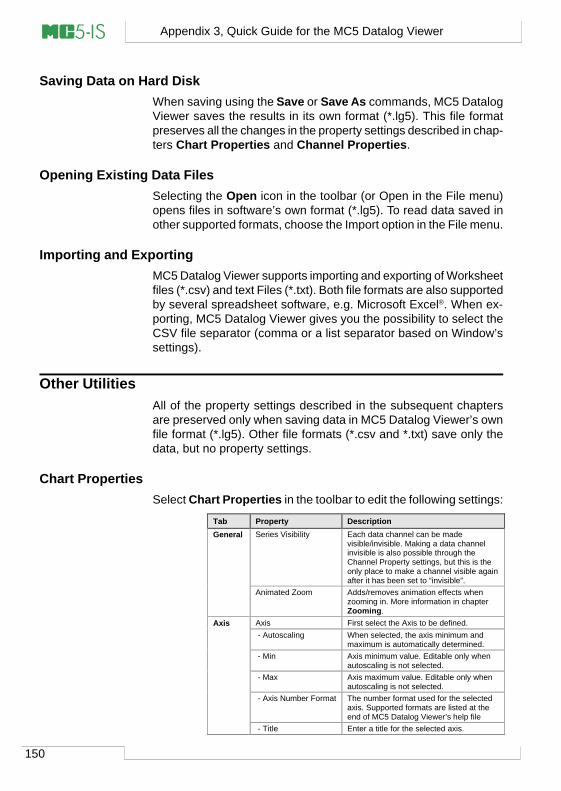
150
Appendix 3, Quick Guide for the MC5 Datalog Viewer
Saving Data on Hard DiskWhen saving using the Save or Save As commands, MC5 DatalogViewer saves the results in its own format (*.lg5). This file formatpreserves all the changes in the property settings described in chap-ters Chart Properties and Channel Properties.
Opening Existing Data FilesSelecting the Open icon in the toolbar (or Open in the File menu)opens files in software’s own format (*.lg5). To read data saved inother supported formats, choose the Import option in the File menu.
Importing and ExportingMC5 Datalog Viewer supports importing and exporting of Worksheetfiles (*.csv) and text Files (*.txt). Both file formats are also supportedby several spreadsheet software, e.g. Microsoft Excel®. When ex-porting, MC5 Datalog Viewer gives you the possibility to select theCSV file separator (comma or a list separator based on Window’ssettings).
Other UtilitiesAll of the property settings described in the subsequent chaptersare preserved only when saving data in MC5 Datalog Viewer’s ownfile format (*.lg5). Other file formats (*.csv and *.txt) save only thedata, but no property settings.
Chart PropertiesSelect Chart Properties in the toolbar to edit the following settings:
Tab Property DescriptionGeneral Series Visibility Each data channel can be made
visible/invisible. Making a data channelinvisible is also possible through theChannel Property settings, but this is theonly place to make a channel visible againafter it has been set to “invisible”.
Animated Zoom Adds/removes animation effects whenzooming in. More information in chapterZooming.
Axis Axis First select the Axis to be defined. - Autoscaling When selected, the axis minimum and
maximum is automatically determined. - Min Axis minimum value. Editable only when
autoscaling is not selected. - Max Axis maximum value. Editable only when
autoscaling is not selected. - Axis Number Format The number format used for the selected
axis. Supported formats are listed at theend of MC5 Datalog Viewer’s help file
- Title Enter a title for the selected axis.
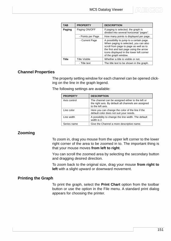
151
Channel PropertiesThe property setting window for each channel can be opened click-ing on the line in the graph legend.
The following settings are available:
ZoomingTo zoom in, drag you mouse from the upper left corner to the lowerright corner of the area to be zoomed in to. The important thing isthat your mouse moves from left to right.You can scroll the zoomed area by selecting the secondary buttonand dragging desired direction.
To zoom back to the original size, drag your mouse from right toleft with a slight upward or downward movement.
Printing the GraphTo print the graph, select the Print Chart option from the toolbarbutton or use the option in the File menu. A standard print dialogappears for choosing the printer.
TAB PROPERTY DESCRIPTIONPaging Paging ON/OFF If paging is selected, the graph is
divided into several horizontal “pages”. - Points per Page How many points is displayed per page. - Current Page A possibility to jump to a certain page.
When paging is selected, you can alsoscroll from page to page as well as tothe first and last page using the arrowicons displayed in the lower left cornerof the graph window.
Title Title Visible Whether a title is visible or not. - Title text The title text to be shown in the graph.
PROPERTY DESCRIPTIONAxis control The channel can be assigned either to the left or
the right axis. By default all channels are assignedto the left axis.
Line color Here you can change the color of the line if thedefault color does not suit your needs.
Line width A possibility to change the line width. The defaultwidth is 2.
Series name Give the Channel a more descriptive name.
MC5 Datalog Viewer
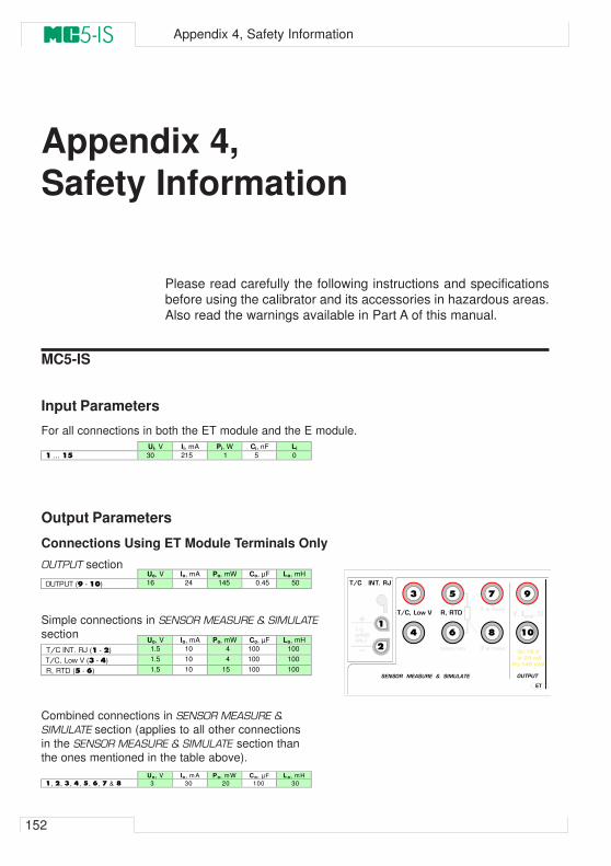
152
Appendix 4, Safety Information
Appendix 4,Safety Information
Please read carefully the following instructions and specificationsbefore using the calibrator and its accessories in hazardous areas.Also read the warnings available in Part A of this manual.
MC5-IS
Input Parameters
For all connections in both the ET module and the E module.
Output Parameters
Connections Using ET Module Terminals Only
OUTPUT section
Ui, V Ii, mA Pi, W Ci, nF Li
1 … 15 30 215 1 5 0
Simple connections in SENSOR MEASURE & SIMULATE
section
Combined connections in SENSOR MEASURE &
SIMULATE section (applies to all other connectionsin the SENSOR MEASURE & SIMULATE section thanthe ones mentioned in the table above).
Uo, V Io, mA Po, mW Co, µF Lo, mH
OUTPUT (9 - 10) 16 24 145 0.45 50
Uo, V Io, mA Po, mW Co, µF Lo, mH
T/C INT. RJ (1 - 2) 1.5 10 4 100 100
T/C, Low V (3 - 4) 1.5 10 4 100 100
R, RTD (5 - 6) 1.5 10 15 100 100
Uo, V Io, m A Po, mW Co, µF Lo, mH
1, 2, 3, 4, 5, 6, 7 & 8 3 30 20 100 30
qL`I=içï=s=
lrqmrq
bq
qL`===fkqK=og
pbkplo==jb^prob==C==pfjri^qb
s
sI=IIII I=ëáåâoI=oqa
=rçW=NS=s
= fçW=OQ=ã^
=mçW=NQR=ãt
qL`=
tfobp=
lkiv
3
4
5
6
7
8
9
101
2
Q=ï=ãÉ~ë
P=ï=ãÉ~ëãÉ~ëLëáã
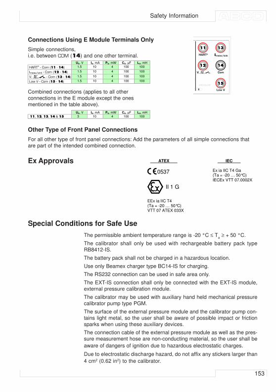
153
Safety Information
Connections Using E Module Terminals Only
Simple connections,i.e. between COM (14) and one other terminal.
Combined connections (applies to all otherconnections in the E module except the onesmentioned in the table above).
Uo, V Io, mA Po, mW Co, µF Lo, mH
HART® - Com (11 - 14) 1.5 10 4 100 100
Imeas/sink - Com (12 - 14) 1.5 10 4 100 100
V, - Com (13 - 14) 1.5 10 4 100 100
Low V - Com (15 - 14) 1.5 10 4 100 100
e^oq∆ ãÉ~ëLëáåâ
jb^prob
b
sI====I== `çã
içï=s
=mçW=NQR=ãt
11
12
13
14
15
IIII=
Uo, V Io, mA Po, mW Co, µF Lo, mH
11, 12, 13, 14 & 15 3 10 4 100 100
Other Type of Front Panel Connections
For all other type of front panel connections: Add the parameters of all simple connections thatare part of the intended combined connection.
Ex Approvals
Special Conditions for Safe Use
The permissible ambient temperature range is -20 °C ≤ Ta ≥ + 50 °C.
The calibrator shall only be used with rechargeable battery pack typeRB8412-IS.
The battery pack shall not be charged in a hazardous location.
Use only Beamex charger type BC14-IS for charging.
The RS232 connection can be used in safe area only.
The EXT-IS connection shall only be connected with the EXT-IS module,external pressure calibration module.
The calibrator may be used with auxiliary hand held mechanical pressurecalibrator pump type PGM.
The surface of the external pressure module and the calibrator pump con-tains light metal, so the user shall be aware of possible impact or frictionsparks when using these auxiliary devices.
The connection cable of the external pressure module as well as the pres-sure measurement hose are non-conducting material, so the user shall be
aware of dangers of ignition due to hazardous electrostatic charges.
Due to electrostatic discharge hazard, do not affix any stickers larger than
4 cm2 (0.62 in2) to the calibrator.
ATEX IEC
0537
II 1 G
EEx ia IIC T4 (Ta = -20 … 50°C) VTT 07 ATEX 033X
Ex ia IIC T4 Ga (Ta = -20 … 50°C) IECEx VTT 07.0002X
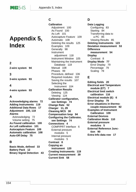
154
Appendix 5, Index
Appendix 5,Index
22-wire system 94
33-wire system 93
44-wire system 93
AAcknowledging alarms 72Adding Instruments 119Additional Data Rows 17Adjustment 100, 118Alarms
Acknowledging 72Volume setting 75
As Found calibration 100As Left calibration 101Autocapture Feature 109Automatic calibration 108Auto-Off Delay 75
BBasic Mode, defined 33Battery Pack 12Binary Signal Detection 43
CCalibration
Adjustment 100As Found 100As Left 101Autocapture Feature 109Automatic 108Deleting the results 125Examples 109Generally 98Instrument
adjustment 118Instrument Window 105Maintaining the Instrument
Database 119Manual 108Phases 99Procedure, defined 106Required modules 102Saving the results 107Selecting the
Instrument 104Calibration Results
Deleting 125Viewing 124
Calibrator configuration,see Settings 74
Change Rate 52Charger 11, 29Cleaning MC5 30Compensation loop 94Configuring the Calibrator,
see Settings 74Connections 4
COMP/PRT Interface 6External pressure
modules 5Internal pressure
modules 5Contrast 8Copying an
instrument 120Creating Instruments 119Current measurement 39Current Sink 58
DData Logging
Configuring 83Starting 84Transferring data to
a PC 85Viewing Results 85
Deleting Instruments 123Deviation measurement 53Difference
measurement 54Display
Contrast 8Display Mode 77
Error Display 79Percentage 79Scaling 78
EEditing fields 20Electrical and Temperature
module (ET) 7Electrical limit switch
calibration 116Electrical module (E) 6Error Display 79Error situations in thermo-
couple measurement 92Examples of Instrument
Calibration 109External DevicesCalibration Mode 110External pressure
modules 5External Reference Junc-
tion 90Extra Info data row 17
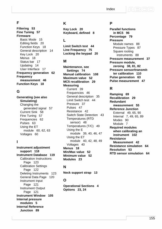
155
Index
FFiltering 53Fine Tuning 57Firmware
Basic Mode 15Editing fields 20Function Keys 18General description 14Key Lock 20Menus 18Status bar 17Updating 14User Interface 17
Frequency generation 62Frequency
measurement 46Function Keys 18
GGenerating (see also
Simulating)Changing the
generated signal 57Current Sink 58Fine Tuning 57Frequencies 62Pulses 63Using the ET
module 60, 62, 63Voltages 60
IInstrument adjustment
support 118Instrument Database 119
Calibration InstructionsPage 123
Calibration SettingsPage 122
Deleting Instruments 123General Data Page 120Instrument Input
Page 121Instrument Output
Page 121Instrument Window 105Internal pressure
modules 5Internal Reference
Junction 89
KKey Lock 20Keyboard, defined 8
LLimit Switch test 44Line Frequency 75Locking the keypad 20
MMaintenance, see
Settings 74Manual calibration 108Maximum value 52MC5 recalibration 29Measuring
Current 39Frequencies 46General description 35Limit Switch test 44Pressure 37Pulses 47Resistance 42Switch State Detection 43Temperatures (RTD
sensor) 48Temperatures (T/C) 49Using the E
module 39, 40, 46, 47Using the ET
module 40, 42, 48, 49Voltages 40
Menus 18Min/Max value 52Minimum value 52Modules 23
NNeck support strap 13
OOperational Sections 4Options 23, 24
PParallel functions
in MC5 96Percentage 79Pressure
Module names 88Pressure Types 87Square rooting
instruments 88Pressure measurement 37Pressure module,
zeroing 38, 81, 82Pressure sensor/transmit-
ter calibration 110Pulse generation 63Pulse measurement 47
RRamping 69Recalibration 29Redundant
measurement 55Reference Junction
External 49, 65, 90Internal 7, 49, 65, 89Modes 90Module 7
Required moduleswhen calibrating aninstrument 102
ResistanceMeasurement 42
Resistance simulation 64Resolution 53RTD sensor simulation 64
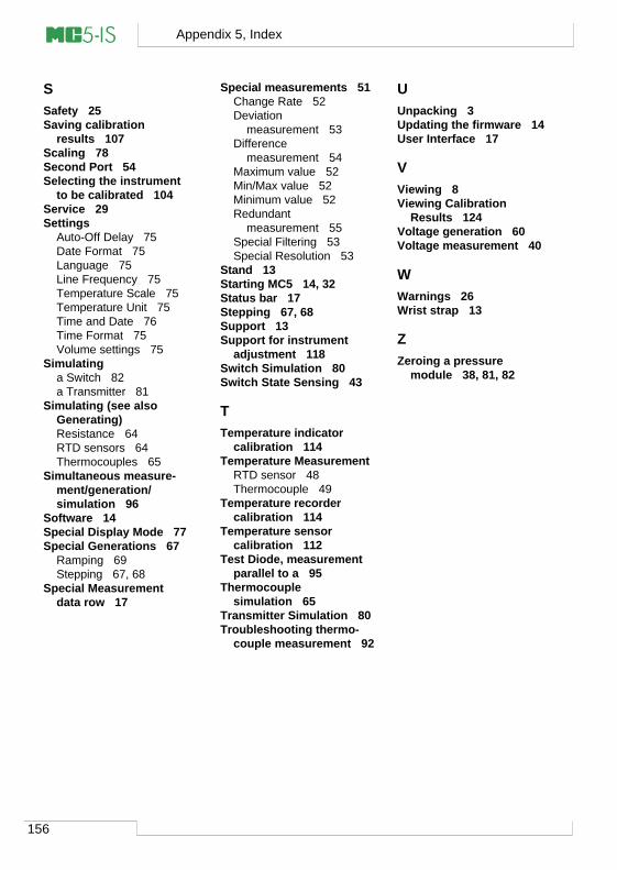
156
Appendix 5, Index
SSafety 25Saving calibration
results 107Scaling 78Second Port 54Selecting the instrument
to be calibrated 104Service 29Settings
Auto-Off Delay 75Date Format 75Language 75Line Frequency 75Temperature Scale 75Temperature Unit 75Time and Date 76Time Format 75Volume settings 75
Simulatinga Switch 82a Transmitter 81
Simulating (see alsoGenerating)Resistance 64RTD sensors 64Thermocouples 65
Simultaneous measure-ment/generation/simulation 96
Software 14Special Display Mode 77Special Generations 67
Ramping 69Stepping 67, 68
Special Measurementdata row 17
Special measurements 51Change Rate 52Deviation
measurement 53Difference
measurement 54Maximum value 52Min/Max value 52Minimum value 52Redundant
measurement 55Special Filtering 53Special Resolution 53
Stand 13Starting MC5 14, 32Status bar 17Stepping 67, 68Support 13Support for instrument
adjustment 118Switch Simulation 80Switch State Sensing 43
TTemperature indicator
calibration 114Temperature Measurement
RTD sensor 48Thermocouple 49
Temperature recordercalibration 114
Temperature sensorcalibration 112
Test Diode, measurementparallel to a 95
Thermocouplesimulation 65
Transmitter Simulation 80Troubleshooting thermo-
couple measurement 92
UUnpacking 3Updating the firmware 14User Interface 17
VViewing 8Viewing Calibration
Results 124Voltage generation 60Voltage measurement 40
WWarnings 26Wrist strap 13
ZZeroing a pressure
module 38, 81, 82