Embed Size (px)
Citation preview

Smart Card Reader Driver Program Reference Manual rev 1.0 April, 2002
Silone Magcard Inc. Page 1 of 34
MCR930Smart Card Reader Driver Program
Reference Manual
Silone Magcard Inc. 1440 Koll Circle #103, San Jose, CA 95112.
Tel: +1-408-441 8858 Fax: +1-408-441-8878 Website: www.magcard.com E-mail : [email protected]
MC930 Smart Card Reader

Smart Card Reader Driver Program Reference Manual rev 1.0 April, 2002
Silone Magcard Inc. Page 2 of 34
TABLE OF CONTENT
1. INTRODUCTION ………………………………………………………………………. 4 2. MCR930 ………………………………………………………………………………… 5 2.1 Overview ………………………………………………………………………… 5
2.2 Communication Speed …………………………………………………………. 5
2.3 MCR930 API …………………………………………………………………….. 5
2.3.1 Interface Data Structure ……………………………………………… 5
2.3.1.1 AC_APDU ………………………………………………….. 6
2.3.1.2 AC_EXTAPDU …………………………………………….. 6
2.3.1.3 AC_SESSION ……………………………………………... 7
2.3.1.4 AC_INFO …………………………………………………... 7
2.3.2 Interface Function Prototypes ……………………………………….. 9
2.3.2.1 AC_Open …………………………………………………... 9
2.3.2.2 AC_Close ………………………………………………….. 10
2.3.2.3 AC_StartSession ………………………………………….. 11
2.3.2.4 AC_EndSession …………………………………………… 12
2.3.2.5 AC_ExchangeAPDU ……………………………………… 13
2.3.2.6 AC_GetInfo ………………………………………………… 14
2.3.2.7 AC_SetOptions ……………………………………………. 15
2.3.3 ACI Commands ……………………………………………………….. 17
2.3.3.1 ACI_Read ………………………………………………….. 17
2.3.3.2 ACI_Write ………………………………………………….. 17
2.3.3.3 ACI_WriteCarry ………………………………………….… 18
2.3.3.4 ACI_WritePr………………………………………………… 18
2.3.3.5 ACI_Erase………………………………………………….. 18
2.3.3.6 ACI_ChangePIN…………………………………………… 19
2.3.3.7 ACI_Verify………………………………………………….. 19
2.3.3.8 ACI_Authenticate………………………………………….. 21
2.3.3.9 ACI_SetFuse……………………………………………….. 21
2.3.3.10 ACI_CardOptions………………………………………….. 22
2.3.3.11 ACI_ReadProtect………………………………………….. 22
2.3.3.12 ACI_SetProtect…………………………………………….. 24
2.3.3.13 ACI_ClearProtect……………………………………….…. 25
2.3.3.14 ACI_LockProtect…………………………………………… 25
2.3.3.15 ACI_WriteAll………………………………………………... 26
2.3.3.16 ACI_SetHE…………………………………………………. 26
2.3.3.17 ACI_BlowFuse……………………………………………... 27
2.3.3.18 ACI_EraseAll……………………………………………….. 27
2.3.3.19 ACI_Reactivate…………………………………………….. 28

Smart Card Reader Driver Program Reference Manual rev 1.0 April, 2002
Silone Magcard Inc. Page 3 of 34
2.4 Programmer Notes ………………………………………………………………. 29
2.4.1 The Xicor Card X76F041 ……………………………………………… 29
2.4.2 The Xicor Card X24645 and the IIC card ……………………………. 30
2.4.3 The AM221 (SLE4436, GAM226) type ………………………………. 31
2.4.4 Secret code verification ………………………………………………... 31
2.4.5 The Xicor Card X76F128 / X76F640 …………………………………. 32
2.4.6 The Xicor Card X76F100 ……………………………………………… 32
Appendix A : Table of error codes …………………………………………………………. 33
Appendix B : Supporting Memory Card Commands ……………………………………... 34
Appendix C : Table of card types compatibility …………………………………………… 35

Smart Card Reader Driver Program Reference Manual rev 1.0 April, 2002
Silone Magcard Inc. Page 4 of 34
1. INTRODUCTION
This manual describes the use of MCR930 interface software to program the MC930 smart
card reader. It is a set of library functions implemented for the application programmers to
operate the MC930 smart card reader and the inserted smart cards. Currently, it is supplied in
the form of DOS libraries, 16-bit DLL (for Windows3.1) and 32-bit DLL (for Windows
95/98/NT). It can be programmed using the popular development tools like Visual C/C++,
Borland C/C++, Visual Basic, Delphi, FoxPro, etc…
Depending on the reader model, MC930 series of smart card readers can be connected to the
PC via the RS/232 interface or USB interface. The connecting interfaces of different model of
readers are summarized as follow:
Model Numbers Connecting interface
MC930S, MC930S-S
Serial RS/232
MC930U, MC930U-S
USB interface
Even though the hardware communication interface can be different, application programs
can still be using the same API (Application Programming Interface) for operating the smart
card readers. Actually, the purpose of using the MCR930 library is to provide the programmer
with a simple and consistent interface over all possible hardware. It is the responsibility of the
MCR930 library to handle the communication details, parameter conversions and error
handling. The architecture of the MCR930 library can be visualized as the following diagram:
MC930 Series of
Smart Card Reader
CardEasy
MCR930
DOS / Windows
Application Program
Driver Program
Operating System
PC Reader
RS-232 / USB
Figure 1.1
Layer

Smart Card Reader Driver Program Reference Manual rev 1.0 April, 2002
Silone Magcard Inc. Page 5 of 34
2. MCR930 2.1 Overview MCR930 is a set of high-level functions provided for the application software to use. It
provides a consistent application programming interface (MCR930 API) for the application to
operate on the card reader and the corresponding inserted card. MCR930 communicates with
the MC930 reader via the communication port facilities provided by the operating system.
MCR930 is supposed to be platform independent provided that there is a minor modification
on the communication module of the MCR930 to adapt to different operating environment.
2.2 Communication Speed The MCR930 library controls the communication speed between the reader and the PC. For
those readers using the serial RS232 connection, the default communication baud rate
(factory setting) is 9600bps, no parity, eight bits and one stop bit. A higher speed of
115200bps can be achieved by using software command issuing from the host. If you are not
sure about the factory setting of your readers, you can always use the MC_AUTODETECT
option in your AC_Open command for the driver to detect the communication speed
automatically. Please notice that the above communication speeds setting apply only on
those readers using the RS232 connection. For the PS/2 type and the USB type of
connection, the speed is fixed at 9600bps and 1.5Mbps respectively.
2.3 MCR930 API The MCR930 Application Programming Interface (API) defines a common way of accessing
the MC930 reader. Application programs invoke MCR930 through the interface functions and
perform operations on the inserted card through the using of ACI commands. The header file
MCR930.H is available for the program developer which contains all the function prototypes
and macros described below.
2.3.1 Interface Data Structure The MCR930 API makes use of several data structures to pass parameters between
application programs and the library driver. These data structures are defined in the header
file MCR930.H and they are discussed below:

Smart Card Reader Driver Program Reference Manual rev 1.0 April, 2002
Silone Magcard Inc. Page 6 of 34
2.3.1.1 AC_APDU typedef struct { BYTE CLA; BYTE INS; BYTE P1; BYTE P2; INT16 Lc; INT16 Le; BYTE DataIn[256]; BYTE DataOut[256]; WORD16 Status; } AC_APDU;
The AC_APDU data structure is used in the AC_ExchangeAPDU function for the passing of
commands and data information into the smart card. For memory card operation, please refer
to section 0 for the definition of fields’ value. For MCU card (T=0,T=1) operation, these values
are specific to the smart card operating system. You must have the card reference manual
before you can perform any valid operations on the card. Please notice that Lc representing
the data length going into the card and Le representing the data length expecting from the
card.
Name Input/Output Description
CLA I Instruction Class
INS I Instruction Code
P1 I Parameter 1
P2 I Parameter 2
Lc I Length of command data (DataIn)
Le I/O Length of response data (DataOut)
DataIn I Command data buffer
DataOut O Response data buffer
Status O Execution status of the command
2.3.1.2 AC_EXTAPDU typedef struct { BYTE CLA; BYTE INS; INT16 P1; INT16 P2; INT16 Lc; INT16 Le; BYTE DataIn[256]; BYTE DataOut[256]; WORD16 Status; } AC_EXTAPDU;

Smart Card Reader Driver Program Reference Manual rev 1.0 April, 2002
Silone Magcard Inc. Page 7 of 34
The AC_EXTAPDU data structure is used in the AC_ExchangeAPDU function for the passing
of commands and data information into the smart card. Thus usage of AC_EXTAPDU is the
same as AC_APDU.
Name Input/Output Description
CLA I Instruction Class
INS I Instruction Code
P1 I Parameter 1
P2 I Parameter 2
Lc I Length of command data (DataIn)
Le I/O Length of response data (DataOut)
DataIn I Command data buffer
DataOut O Response data buffer
Status O Execution status of the command
2.3.1.3 AC_SESSION typedef struct {
BYTE CardType; // Card type selected BYTE SCModule; // Selected security module.
//Use only when card type = AC_SCModule BYTE ATRLen; // Length of the ATR BYTE ATR[128]; // ATR string BYTE HistLen; // Length of the Historical data BYTE HistOffset; // Offset of the Historical data
// from the beginning of ATR INT16 APDULenMax; // Max. APDU supported
} AC_SESSION; The AC_SESSION data structure is used in the AC_StartSession function call for the retrieval
of ATR information from the smart card. Before calling AC_StartSession, the program needs
to specify the value of CardType. After calling the function, the ATR string can be found in
ATR field and the length is stored in ATRLen.
Name Input/Output Description
CardType I The card type selected for operation (refer to Appendix C for
CardType)
SCModule I The security module selected for operation. (The value is used only
when card type = AC_SCModule)
ATRLen O Length of the ATR string
ATR O Attention to reset (ATR) string
HistLen O Obsolete field – not used anymore
HistOffset O Obsolete field – not used anymore
APDULenMax O Obsolete field - not used anymore
2.3.1.4 AC_INFO typedef struct {
INT16 nMaxC; // Maximum number of command data bytes INT16 nMaxR; // Maximum number of data bytes that

Smart Card Reader Driver Program Reference Manual rev 1.0 April, 2002
Silone Magcard Inc. Page 8 of 34
// can be requested in a response INT16 CType; // The card types supported by the reader BYTE CStat; // The status of the card reader BYTE CSel; // The current selection of card type BYTE szRev[10]; // The 10 bytes firmware type and
// revision code INT16 nLibVer; // Library version Long lBaudRate; // Current Running Baud Rate
} AC_INFO; The AC_INFO data structure is used in the AC_GetInfo function call for the retrieval of reader
related information. Their meaning are described as follow:
Name Input/Output Description
nMaxC O The maximum number of command data byte (DataIn) that can be accepted in
the ExchangeAPDU command
nMaxR O The maximum number of response data byte (DataOut) that will be appeared in
the ExchangeAPDU command
CType O The card types supported by the reader
(For details, please look at the MC930 reference manual)
Cstat O The status of the card reader
Bit0 = card present (1) or absent (0)
Bit1 = card powered up (1) or powered down (0)
szRev[10] O The firmware revision code
nLibVer O Library version (e.g. 310 is equal to version 3.10)

Smart Card Reader Driver Program Reference Manual rev 1.0 April, 2002
Silone Magcard Inc. Page 9 of 34
2.3.2 Interface Function Prototypes Generally, a program is required to call AC_Open first to obtain a handle. The handle is
required for subsequent calls to AC_StartSession, AC_ExchangeAPDU, AC_EndSession and
AC_Close. The inserted card can be powered up by using the AC_StartSession function and
card commands can be exchanged with the inserted card using the AC_ExchangeAPDU
function. Moreover, AC_SetOptions and AC_GetInfo are two commands that can be used to
set and read the various information of the reader.
2.3.2.1 AC_Open This function opens a port and returns a valid reader handle for the application program.
Format: INT16 AC_DECL AC_Open (INT16 ReaderType, INT16 ReaderPort);
Input Parameters: The table below lists the parameters for this function (you can refer to MCR930.H for the
corresponding value): Parameters Definition / Values
ReaderType3 Reader type and communication speed.
MC930 = Target reader is MC930 (57600bps)
MC930_57600 = Target reader is MC930 (57600bps)
MC930_19200 = Target reader is MC930 (19200bps)
MC930_115200 = Target reader is MC930 (115200bps)
MC930_9600 = Target reader is MC930 (9600bps)
MC_AUTODETECT1 = Auto detect the target reader
ReaderPort The port that connected with the reader.
AC_COM1 = Standard communication port 1
AC_COM2 = Standard communication port 2
AC_COM3 = Standard communication port 3 (Valid only on the Win32 driver)
AC_COM4 = Standard communication port 4 (Valid only on the Win32 driver)
AC_USB = Using the USB communication port
AC_PCSC = Using the PCSC component to access the reader
Returns: The return value is negative and contains the error code when the function encounters an
error during operation. Otherwise, it returns a valid reader handle. Please refer to appendix A
for the detailed description and meaning of the error codes.
Examples: // open a port to a MC930 reader connected to COM1 INT16 hReader; hReader = AC_Open(MC930,AC_COM1); Remarks:

Smart Card Reader Driver Program Reference Manual rev 1.0 April, 2002
Silone Magcard Inc. Page 10 of 34
1. If the user select MC_AUTODETECT to open a reader in the first time, the library will try to reset the reader and
wait for the response message from the reader. This may take some time (around 2-3 seconds) for the library to
complete this operation.
2. When an MC930 is reset, the green LED will flash three times.
3. When the application want to access the security module, it needs to open (use the AC_Open command) the
reader for the second time to get a different handler for the handling of the security module session.
4. The option of AC_USB is available only in the Windows 98 and Windows 2000 platform.
The option of AC_PCSC is available only in the platform with the Microsoft PCSC base components installed.
The driver will select the first available PCSC reader for operation. In order for the correct operation of the
reader, you need to make sure that the first available PCSC reader is a smart card reader from Magcard.
2.3.2.2 AC_Close This function closes a previously opened reader port.
Format:
INT16 AC_DECL AC_Close (INT16 hReader);
Input Parameters:
The table below lists the parameters for this function
Parameters Definition / Values
hReader A valid reader handle previously opened by AC_Open()
Returns :
The return value is zero if the function is successful. Otherwise, it returns a negative value
containing the error code. For the detailed meaning of the error code, please refer to
appendix A.
Examples :
// Close a previously opened port
INT16 RtnCode;
RtnCode = AC_Close(hReader);

Smart Card Reader Driver Program Reference Manual rev 1.0 April, 2002
Silone Magcard Inc. Page 11 of 34
2.3.2.3 AC_StartSession This function starts a session with a selected card type and updates the session structure with
the values returned by the card Answer-To-Reset (ATR). A session is started by a card reset
and it is ended by either another card reset, a power down of the card or the removal of a
card from the reader. Note that this function will power up the card and perform a card reset.
Format: INT16 AC_DECL AC_StartSession (INT16 hReader, AC_SESSION FAR
*Session);
Input Parameters: The table below listed the parameters for this function
Parameters Definition / Values
hReader A valid reader handle returned by AC_Open()
Session.CardType The selected card type for this session (please refer to Appendix C for card type
selection)
Session.SCModule The selected security module number
(Required only when card type =AC_SCModule)
Output Parameters:
The table below listed the parameters returned by this function
Parameters Definition / Values
Session.ATR Answer to Reset returned by the card
Session.ATRLen Length of the answer to reset
Session.HistLen Length of the historical data
Session.HistOffset Offset of the historical data
Session.APDULenMax Maximum length of APDU supported
Returns:
The return value is zero if the function is successful. Otherwise, it returns a negative value
containing the error code. For the detailed meaning of the error code, please refer to
appendix A.

Smart Card Reader Driver Program Reference Manual rev 1.0 April, 2002
Silone Magcard Inc. Page 12 of 34
Examples: // Prepare Session structure for AM104 memory card
INT16 RtnCode,i;
AC_SESSION Session;
Session.CardType = AC_AM104; // Card type = AM104
//Start a session on previously opened port
RtnCode = AC_StartSession(hReader, &Session);
// Print the card ATR
printf("Card Answer to Reset : ");
for (i = 0; i < (INT16) Session.ATRLen; i++)
printf(" %02X",Session.ATR[i]);
Remarks:
1)
When no card type is selected (i.e. Session.CardType = 0), the reader will try to detect the inserted card type
automatically. However, while the reader can distinguish the T=0 card, T=1 card and synchronous memory card, it
cannot distinguish different types of memory card.
2)
When AM221 card type is selected (i.e. Session.CardType = AC_AM221), the library will check the backup bits and
try to recover the lost token when necessary.
2.3.2.4 AC_EndSession This function ends a previously started session and powers off the card.
Format: INT16 AC_DECL AC_EndSession (INT16 hReader);
Input Parameters: The table below lists the parameters for this function Parameters Definition / Values
hReader A valid reader handle returned by AC_Open()
Returns: The return value is zero if the function is successful. Otherwise, it returns a negative value
containing the error code. For the detailed meaning of the error code, please refer to
appendix A.
Examples: //End session on a previously started session
RtnCode = AC_EndSession(hReader);

Smart Card Reader Driver Program Reference Manual rev 1.0 April, 2002
Silone Magcard Inc. Page 13 of 34
2.3.2.5 AC_ExchangeAPDU This function sends an APDU command to a card via the opened port and returns the card's
response. Please refer Section 2.3.3 ACI Commands for detail description on how to fill in
the parameters.
Format: INT16 AC_DECL AC_ExchangeAPDU (INT16 hReader, AC_APDU FAR *Apdu);
Input Parameters: The table below listed the parameters for this function
Parameters Definition / Values
hReader A valid reader handle returned by AC_Open()
Apdu.CLA Instruction Class (Please refer Section 2.3.3 ACI Commands for detail description)
Apdu.INS Instruction Code (Please refer Section 2.3.3 ACI Commands for detail description)
Apdu.P1 Parameter 1 (Please refer Section 2.3.3 ACI Commands for detail description)
Apdu.P2 Parameter 2 (Please refer Section 2.3.3 ACI Commands for detail description)
Apdu.DataIn Data buffer to send
Apdu.Lc Number of bytes in Apdu.DataIn to be sent
Apdu.Le Number of bytes expected to receive
Output Parameters: The table below listed the parameters returned by this function Parameters Definition / Values
Apdu.DataOut Data buffer containing the card response
Apdu.Le Number of bytes received in Apdu.DataOut
Apdu.Status Status bytes SW1, SW2 returned by the card
Returns: The return value is zero if the function is successful. Otherwise, it returns a negative value
containing the error code. For the detailed meaning of the error code, please refer to
appendix A.

Smart Card Reader Driver Program Reference Manual rev 1.0 April, 2002
Silone Magcard Inc. Page 14 of 34
Examples: // Read 8 bytes from AM104 starting from address 0 INT16 RtnCode,i; AC_APDU Apdu; Apdu.CLA = 0x00; // Instruction Class Apdu.INS = ACI_Read; // Command Apdu.P1 = 0x00; // MSB of starting address Apdu.P2 = 0x00; // LSB of starting address Apdu.Lc = 0x00; // No input data for this command Apdu.Le = 0x08; // Read 8 bytes data //Exchange APDU with the MC930 reader RtnCode = AC_ExchangeAPDU(hReader, &Apdu); if (RtnCode >= 0) { // print the data printf("Data : "); for (i=0; i < (INT16) Apdu.Le; i++) printf(" %02X",Apdu.DataOut[i]); // print the status bytes printf("Card Status(SW1 SW2)=%04X",Apdu.Status);
2.3.2.6 AC_GetInfo This function retrieve information related to the currently selected reader.
Format : INT16 AC_DECL AC_GetInfo (INT16 hReader, AC_INFO FAR *Info);
Input Parameters: The table below lists the parameters for this function
Parameters Definition / Values
hReader A valid reader handle returned by AC_Open()
Output Parameters: The table below lists the parameters returned by this function
Parameters Definition / Values
Info.szRev Revision code for the selected reader.
Info.nMaxC The maximum number of command data bytes.
Info.nMaxR The maximum number of data bytes that can be requested to be transmitted in a
response
Info.CType The card types supported by this reader
Info.CStat The current status of the reader
00H = no card inserted
01H = card inserted, not powered up
03H = card powered up
Info.CSel The currently selected card type
Info.nLibVer Current library version
(e.g. 310 is equal to version 3.10)
Smart Card Reader Driver Program Reference Manual rev 1.0 April, 2002
Silone Magcard Inc. Page 15 of 34
Parameters Definition / Values
Info.lBaudRate The current running baud rate
Returns: The return value is zero if the function is successful. Otherwise, it returns a negative value containing the error code. For the detailed meaning of the error code, please refer to appendix A.
Examples: // Get the revision code of the currently selected reader INT16 RtnCode; AC_INFO Info; RtnCode = AC_GetInfo(hReader, &Info); printf("Reader Operating System ID : %s",Info.szRev);
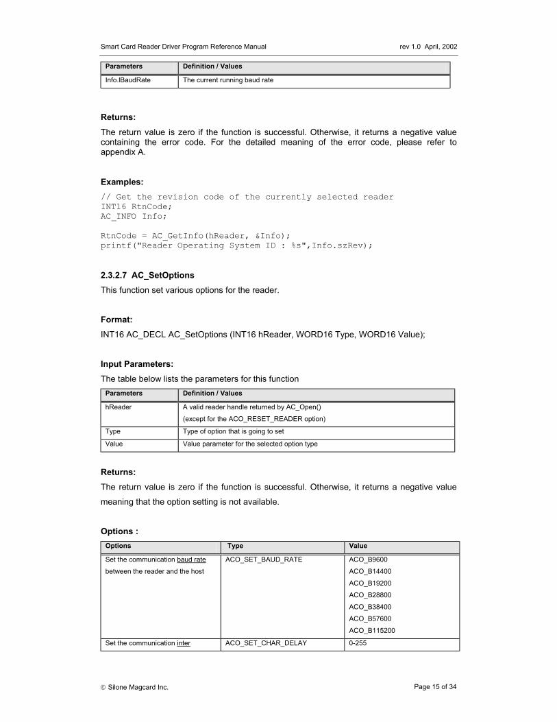
2.3.2.7 AC_SetOptions This function set various options for the reader.
Format: INT16 AC_DECL AC_SetOptions (INT16 hReader, WORD16 Type, WORD16 Value);
Input Parameters: The table below lists the parameters for this function
Parameters Definition / Values
hReader A valid reader handle returned by AC_Open()
(except for the ACO_RESET_READER option)
Type Type of option that is going to set
Value Value parameter for the selected option type
Returns: The return value is zero if the function is successful. Otherwise, it returns a negative value
meaning that the option setting is not available.
Options :
Options Type Value
Set the communication baud rate
between the reader and the host
ACO_SET_BAUD_RATE ACO_B9600
ACO_B14400
ACO_B19200
ACO_B28800
ACO_B38400
ACO_B57600
ACO_B115200
Set the communication inter ACO_SET_CHAR_DELAY 0-255

Smart Card Reader Driver Program Reference Manual rev 1.0 April, 2002
Silone Magcard Inc. Page 16 of 34
Options Type Value
character delay between the reader
and the host
Set the communication to the
highest possibility
ACO_SET_BAUD_HIGHEST 0
Reset the reader
(hReader is not necessary valid)
ACO_RESET_READER AC_COM1
AC_COM2
Enable the reader to issue the
GET_RESPONSE command
automatically
(only valid for the MCU card)
ACO_ENABLE_GET_RESPONSE SW1 + “00”
(GET_RESPONSE will be issued
automatically when this SW1 is
returned from the card)
Disable the automatic issue of the
GET_RESPONSE command
(this is the default option of the
reader)
ACO_DISABLE_ GET_RESPONSE 0
Eject card from the card reader
(if applicable)
ACO_EJECT_CARD 0
Check the reader is supporting the
“eject card” option or not*
ACO_GET_READER_CAPABILITIE
S
0
Enable / Disable card insertion /
removal notification message
ACO_SET_NOTIFICATION 1 =enable notification
2 =disable notification
* Function return 0 when that option is supported, otherwise it is not supported Examples: // Set the communication baud rate to the highest possible setting INT16 RtnCode; RtnCode = AC_SetOption(hReader, ACO_SET_BAUD_HIGHEST, 0); if (RtnCode < 0)
printf("Set option failed\n");
Smart Card Reader Driver Program Reference Manual rev 1.0 April, 2002
Silone Magcard Inc. Page 17 of 34
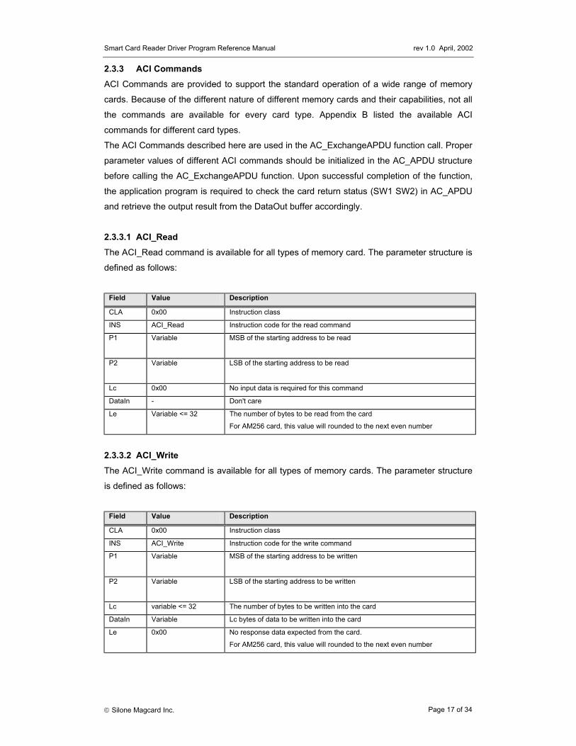
2.3.3 ACI Commands ACI Commands are provided to support the standard operation of a wide range of memory
cards. Because of the different nature of different memory cards and their capabilities, not all
the commands are available for every card type. Appendix B listed the available ACI
commands for different card types.
The ACI Commands described here are used in the AC_ExchangeAPDU function call. Proper
parameter values of different ACI commands should be initialized in the AC_APDU structure
before calling the AC_ExchangeAPDU function. Upon successful completion of the function,
the application program is required to check the card return status (SW1 SW2) in AC_APDU
and retrieve the output result from the DataOut buffer accordingly.
2.3.3.1 ACI_Read The ACI_Read command is available for all types of memory card. The parameter structure is
defined as follows:
Field Value Description
CLA 0x00 Instruction class
INS ACI_Read Instruction code for the read command
P1 Variable MSB of the starting address to be read
P2 Variable LSB of the starting address to be read
Lc 0x00 No input data is required for this command
DataIn - Don't care
Le Variable <= 32 The number of bytes to be read from the card
For AM256 card, this value will rounded to the next even number
2.3.3.2 ACI_Write The ACI_Write command is available for all types of memory cards. The parameter structure
is defined as follows:
Field Value Description
CLA 0x00 Instruction class
INS ACI_Write Instruction code for the write command
P1 Variable MSB of the starting address to be written
P2 Variable LSB of the starting address to be written
Lc variable <= 32 The number of bytes to be written into the card
DataIn Variable Lc bytes of data to be written into the card
Le 0x00 No response data expected from the card.
For AM256 card, this value will rounded to the next even number

Smart Card Reader Driver Program Reference Manual rev 1.0 April, 2002
Silone Magcard Inc. Page 18 of 34
2.3.3.3 ACI_WriteCarry The ACI_WriteCarry command is available for EEPROM non-reloadable token counter cards.
The parameter structure is defined as follows:
Name Value Description
CLA 0x00 Instruction class
INS ACI_WriteCarry Instruction code for the write carry command
P1 0x01,0x02 or 0x03 0x01 = write carry without backup
0x02 = write with backup
0x03 = write carry with backup
P2 Variable LSB of the starting address to be written
Lc 0x01 Only one byte at a time is allowed for this command
DataIn Variable DataIn[0] contains the byte that is to be written into the card
Le 0x00 No response data expected from the card
2.3.3.4 ACI_WritePr The ACI_WritePr command is available for some memory cards with protected memory logic.
The parameter structure is defined as follows:
Name Value Description
CLA 0x00 Instruction class
INS ACI_WritePr Instruction code for the write protect command
P1 Variable MSB of the starting address to be written
P2 Variable LSB of the starting address to be written
Lc variable <= 32 The number of bytes to be written into the card
DataIn Variable Lc bytes of data to be written into the card
Le 0x00 No response data expected from the card
2.3.3.5 ACI_Erase The ACI_Erase command is available for some memory cards with the erasing capability. The
parameter structure is defined as follows:
Name Value Description
CLA 0x00 Instruction class
INS ACI_Erase Instruction code for the erase command
P1 Variable MSB of the starting address to be erased
P2 Variable LSB of the starting address to be erased
Lc variable <= 32 The number of bytes to be erased from the card
DataIn - Don't care
Le 0x00 No response data expected from the card

Smart Card Reader Driver Program Reference Manual rev 1.0 April, 2002
Silone Magcard Inc. Page 19 of 34
2.3.3.6 ACI_ChangePIN The ACI_ChangePIN command is available for the AM2KS / X76F041 / X76F128 / X76F640
card. For the AM8KS, it is required to use the ACI_Write command to do the change PIN
operation. The parameter structure of ACI_ChangePIN is defined as follows:
Field Name
Value Description
CLA 0x00 Instruction class
INS ACI_ChangePIN Instruction code for the change PIN command
P1 variable Please refer to the table in command ACI_Verify for the definition of this field
P2 - Don't Care
Lc variable The length of the PIN
DataIn variable The new PIN value
Le 0x00 No response data expected from the card
In order for the password (PIN) of X76F041 card can be changed, the application must verify
the old password correctly before the ACI_ChangePIN command can be executed. If the read
password is verified, only the read password can be changed. If the write password is
verified, only the write password can be changed. However, when the configuration password
is verified, all three passwords can be changed.
2.3.3.7 ACI_Verify The ACI_Verify command is available for some memory cards with the secret code capability.
It is not enough to check alone the code returned from the function AC_ExchangeAPDU to
determine that the verification is successful or not. Application program must check the data
returning back from the card for the interpretation of whether the verification is successful or
not. Please see the programmer notes for detail.
Field Value Description
CLA 0x00 Instruction class
INS ACI_Verify Instruction code for the verify command
P1 variable Key Index, see the table below for the description
P2 - Don't Care
Lc variable Number of bytes of the key
DataIn variable Lc bytes of key value to be verified by the card
Le variable Case when : -
AC_AM2KS : Le = 4
AC_AM8KS : Le = 3
otherwise : Le = 0

Smart Card Reader Driver Program Reference Manual rev 1.0 April, 2002
Silone Magcard Inc. Page 20 of 34
Depending on the card type of the current session, Key Index (P1) can contain any of the
following values.
Card Type Key
Index Length (bytes)
Description
AC_AM104 0x00 3 Transport code
AC_AM221 0x00 3 Transport code
AC_SLE4404 0x00 2 Card secure code (GPM416) / security code (SLE4404)
0x01 4 Erase code (GPM416) / system code (SLE4404)
AC_GPM896 0x00 2 Card secure code
0x01 6 Erase code 1
0x02 4 Erase code 2
AC_AT101 0x00 2 Security code
0x01 4 Zone 1 erase key
AC_AT102 0x00 2 Security code
0x01 6 Zone 1 erase key
0x02 4 Zone 2 erase key
AC_AT1604 0x00 2 Security code
0x01 2 Zone 1 erase key
0x02 2 Zone 2 erase key
0x03 2 Zone 3 erase key
0x04 2 Zone 4 erase key
0x05 2 Zone 1 security code
0x06 2 Zone 2 security code
0x07 2 Zone 3 security code
0x08 2 Zone 4 security code
AC_AM2KS 0x00 3 Security code
AC_AM8KS 0x00 2 Security code
AC_X76F041 0x00 8 Write password
0x01 8 Read password
0x02 8 Configuration password
AC_X76F128 0x00 8 Read array 0 password
Or 0x01 8 Read array 1 password
AC_X76F640 0x02 8 Write array 0 password
0x03 8 Write array 1 password
0x04 8 Reset password
AC_X76F100 0x00 8 Write password
0x01 8 Read password

Smart Card Reader Driver Program Reference Manual rev 1.0 April, 2002
Silone Magcard Inc. Page 21 of 34
2.3.3.8 ACI_Authenticate The ACI_Authenticate command is available for some memory cards that can generate a
card authentication certificate. The parameter structure is defined as follows:
Field Value Description
CLA 0x00 Instruction class
INS ACI_Authenticate Instruction code for the authenticate command
P1 Variable Case SLE4436 :
0x00 = Use Key 1
0x01 = Use Key 2
Case ST1333, ST1335:
0x00 always
P2 Variable Case SLE4436: Number of CLK pulses to be supplied to the card for the
computation of each bit of the authentication certificate
Case ST1333,ST1335 : 0x00 always
Lc Variable Case SLE4436 : Lc = 0x06
Case ST1333, ST1335 : Lc = 0x04
DataIn Variable Challenge data to be presented to the card
Le Variable Authentication certificate
Case SLE4436 : Le = 0x02
Case ST1333, ST1335 : Le = 0x01
2.3.3.9 ACI_SetFuse The ACI_SetFuse command is available for some memory cards with the set fuse capability.
The parameter structure is defined as follow:
Field Value Description
CLA 0x00 Instruction class
INS ACI_SetFuse Instruction code for the set fuse command
P1 0x00 or 0x01 or
0xFF
0x00 = Set Fuse PIN to "not connected" (high impedance)
0x01 = Set Fuse PIN to high (5V)
0xFF = Set Fuse PIN to low (0V)
P2 - Don't care
Lc 0x00 No input data for this command
DataIn - Don't care
Le 0x00 No output data expected from this command

Smart Card Reader Driver Program Reference Manual rev 1.0 April, 2002
Silone Magcard Inc. Page 22 of 34
2.3.3.10 ACI_CardOptions The ACI_CardOptions command is available for the IIC card and the XIIC card only. It can be
used to change the page size and the chip select address bits. The parameter structure is
defined as follow:
Field Value Description
CLA 0x00 Instruction class
INS ACI_CardOptions Instruction code
P1 Bitmap for this byte
is:
xAAAxPPP
AAA = Chip select address bits.
PPP = Page size where
000 = 4 bytes
001 = 8 bytes
010 = 16 bytes
011 = 32 bytes
100 = 64 bytes
101 = 64 bytes
110 = 64 bytes
111 = 64 bytes
P2 - Don't care
Lc 0x00 No input data for this command
DataIn - No input data
Le 0x00 No output data expected from this command
2.3.3.11 ACI_ReadProtect The ACI_ReadProtect command is available for the XIIC card, the AM256 card, the AM2KS,
the AM4KP card and the X76F041 card. It can be used to read the block security status and
the block number of the high endurance memory block from the XIIC card or it can be used to
read the write protection register for the AM256 card and the AM4KP card or it can be used to
read the configuration register for the X76F041 card or it can be used to read the security
memory for the AM2KS card. The parameter structure is defined as follow:
Field Value Description
CLA 0x00 Instruction class
INS ACI_ReadProtect Instruction code
P1 - Don’t care
P2 - Don't care
Lc 0x00 No input data for this command
DataIn - No input data
Le variable Case when : -
XIIC : Le = 3
AM256 : Le = 1
AM4KP : Le = 1
X76F041 : Le = 5
AM2KS : Le=4
AM8KS : Le=3

Smart Card Reader Driver Program Reference Manual rev 1.0 April, 2002
Silone Magcard Inc. Page 23 of 34
For XIIC card, this command response with three bytes messages containing the following
information. Byte position Name Meaning
1 START Number of first protected block
2 BLK_CNT Number of blocks protected from block # start
3 HE_BLK Block number of the High Endurance memory block
For AM2KS card, this command response with three bytes messages containing security
memory of the following information. Byte position Name Meaning
1 ERR_CNT Error Counter for SC presentation
2-4 SC Three bytes security code (Visible only after successful security code
verification)
For AM8KS card, this command response with three bytes messages containing security
memory of the following information. Byte position Name Meaning
1 ERR_CNT Error Counter for SC presentation
2-3 SC Two bytes security code (Visible only after successful security code
verification)
For X76F041 card, this command response with five bytes messages containing the
configuration register information. For the details meaning of each byte, please refer back to
the technical specification of the X76F041 chip. Byte position Name Meaning
1 ACR1 Array Control Register 1
2 ACR2 Array Control Register 2
3 CR Configuration Register
4 RR Retry Register
5 RC Retry Counter

Smart Card Reader Driver Program Reference Manual rev 1.0 April, 2002
Silone Magcard Inc. Page 24 of 34
2.3.3.12 ACI_SetProtect The ACI_SetProtect command is available for the XIIC card, the AM256 card, the AM4KP
card and the X76F041 card. For the XIIC, AM256 and the AM4KP card, it can be used to set
the starting block of the write-protection memory area and for the case of XIIC card, it can be
used to set the number of protection block also. Finally for the X76F041, it can be used to set
the configuration register value as described in the ACI_ChangePIN paragraph. The
parameter structure is defined as follow:
Field Value Description
CLA 0x00 Instruction class
INS ACI_SetProtect Instruction code
P1 variable Case when : -
XIIC : P1 = start protecting block (0 ≤ P1 ≤ 0x0F)
AM256 : P1 = start protecting block
AM4KP : P1 = start protecting block
X76F041 : P1 = 0
P2 variable Case when : -
XIIC : P2 = no of blocks to be protected (0 ≤ P2 ≤ 0x0F)
AM256, AM4KP, X76F041 : P2 = 0
Lc variable Case when : -
XIIC, AM256, AM4KP : Lc = 0
X76F041 : Lc = 5
DataIn variable Case when : -
XIIC, AM256, AM4KP : No input data
X76F041 : Configuration Register
Le 0x00 No output data expected from this command

Smart Card Reader Driver Program Reference Manual rev 1.0 April, 2002
Silone Magcard Inc. Page 25 of 34
2.3.3.13 ACI_ClearProtect The ACI_ClearProtect command is available for the AM256 card and the AM4KP card only. It
can be used to set all memory address to “not write-protected”. The parameter structure is
defined as follow:
Field Value Description
CLA 0x00 Instruction class
INS ACI_ClearProtect Instruction code
P1 0x00 must be zero
P2 0x00 must be zero
Lc 0x00 No input data for this command
DataIn - No input data
Le 0x00 No output data expected from this command
2.3.3.14 ACI_LockProtect The ACI_LockProtect command is available for the AM256 card and the AM4KP card only. It
can be used to disable access to the write-protection register irreversibly. The contents of the
write-protection register is not changed and the currently write-protection memory area cannot
be modified any more. The parameter structure is defined as follow:
Field Value Description
CLA 0x00 Instruction class
INS ACI_LockProtect Instruction code
P1 0x00 must be zero
P2 0x00 must be zero
Lc 0x00 No input data for this command
DataIn - No input data
Le 0x00 No output data expected from this command

Smart Card Reader Driver Program Reference Manual rev 1.0 April, 2002
Silone Magcard Inc. Page 26 of 34
2.3.3.15 ACI_WriteAll The ACI_WriteAll command is available for the AM256 / AM4KP / X76F041 / X76F128 /
X76F640. For the case of AM256 card and the AM4KP card, it can be used to fill the
complete card memory with the specific value. For the X76F041 card, it can be used to fill the
complete card with the value 0x00. For the case of X76F128 and X76F640 card, prior to using
this command it must have the “Reset Password” being verified OK. The parameter structure
is defined as follow:
Field Value Description
CLA 0x00 Instruction class
INS ACI_WriteAll Instruction code
P1 0x00 must be zero
P2 0x00 must be zero
Lc variable Case when : -
AM256, AM4KP : Lc = 2
X76FXXX : Lc = 8
DataIn variable Case when : -
AM256, AM4KP : data to be filled
X76F041 : configuration password
Le 0x00 No output data expected from this command
2.3.3.16 ACI_SetHE The ACI_SetHE command is available for the XIIC card only. It can be used to relocate the
High Endurance memory block to the specified block address. The parameter structure is
defined as follow:
Field Value Description
CLA 0x00 Instruction class
INS ACI_SetHE Instruction code
P1 0 ≤ P1 ≤ 0x0F New block number of the High Endurance memory block
P2 - Don’t care
Lc 0x00 No input data for this command
DataIn - No input data
Le 0x00 No output data expected from this command

Smart Card Reader Driver Program Reference Manual rev 1.0 April, 2002
Silone Magcard Inc. Page 27 of 34
2.3.3.17 ACI_BlowFuse The ACI_BlowFuse command is available for the AT101, AT102 and AT1604 cards only. It
can be used to blow the fuse of a card. The parameter structure is defined as follow:
Field Value Description
CLA 0x00 Instruction class
INS ACI_BlowFuse Instruction code
P1 variable MSB of the starting address of the fuse
P2 variable LSB of the starting address of the fuse
Lc 0x00 No input data for this command
DataIn - No input data
Le 0x00 No output data expected from this command
2.3.3.18 ACI_EraseAll The ACI_EraseAll command is available for the AM4KP card and the X76F041 card only. It
can be used to erase the whole card memory with the value 0xFF. The parameter structure is
defined as follow:
Field Value Description
CLA 0x00 Instruction class
INS ACI_WriteAll Instruction code
P1 0x00 must be zero
P2 0x00 must be zero
Lc variable Case when : -
X76F041 : Lc = 8
Others : Lc = 0
DataIn variable Case when : -
X76F041 : configuration password
Le 0x00 No output data expected from this command

Smart Card Reader Driver Program Reference Manual rev 1.0 April, 2002
Silone Magcard Inc. Page 28 of 34
2.3.3.19 ACI_Reactivate The ACI_Reactivate command is available for the X76F128 card and the X76F640 card only.
It can be used to erase the retry counter and reactivate the card. This command is valid only
after the “Reset Password” is verified OK. The parameter structure is defined as follow:
Field Value Description
CLA 0x00 Instruction class
INS ACI_Reactivate Instruction code
P1 0x00 must be zero
P2 0x00 must be zero
Lc 0x00 no input data
DataIn variable no input data
Le 0x00 No output data expected from this command

Smart Card Reader Driver Program Reference Manual rev 1.0 April, 2002
Silone Magcard Inc. Page 29 of 34
2.4 Programmer Notes
Please see the “readme.txt” in the provided diskette for the latest information.
2.4.1 The Xicor Card X76F041 According to the technical specification, the X76F041 is organized in four 128 x 8 bit memory
array. Each block of memory can be read/write protected by the read password/ write
password. The requirement of a password is indicated by the MSB of the address field. If the
memory blocks are not password protected, the four blocks of memory are located in
addresses 0x0000-0x007F, 0x0080-0x00FF, 0x0100-0x017F and 0x0180-0x01FF. If the
memory blocks are password protected, the four blocks of memory are located in addresses
0x8000-0x807F, 0x8080-0x80FF, 0x8100-0x817F and 0x8180-0x81FF. Read / write
operation can be performed across the block boundary but it is up to the application to
handle the case when the adjacent blocks have different protection attributes (e.g. one block
is password protected and the other one is not).
The X76F041 has totally three passwords, namely, the configuration password, the read
password and the write password. These passwords can be verified by using the ACI_Verify
command. Once these passwords are verified OK, the library will remember them. Reading of
the password protected memory blocks is required to have either the read password or the
configuration password. Writing into the password protected memory blocks is required to
have either the write password or the configuration password.
The ACI_ChangePIN command can be used to change the passwords. If the configuration
password is verified OK, all three passwords can be changed. If the read password is verified
OK, only the read password can be change. If the write password is verified OK, only the
write password can be change.
The ACI_ReadProtect and ACI_WriteProtect commands can be used to manage the
configuration registers after the configuration password is verified OK. The detail meaning of
the configuration registers can be found in the X76F041 data book.
Smart Card Reader Driver Program Reference Manual rev 1.0 April, 2002
Silone Magcard Inc. Page 30 of 34
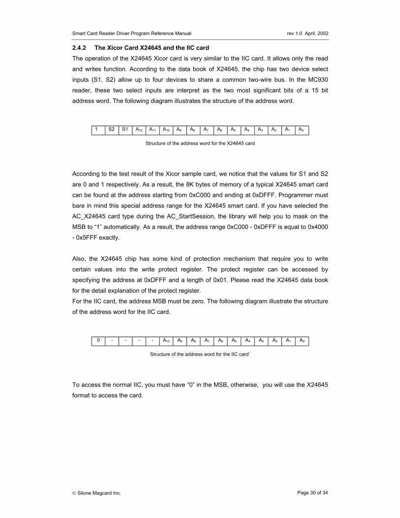
2.4.2 The Xicor Card X24645 and the IIC card The operation of the X24645 Xicor card is very similar to the IIC card. It allows only the read
and writes function. According to the data book of X24645, the chip has two device select
inputs (S1, S2) allow up to four devices to share a common two-wire bus. In the MC930
reader, these two select inputs are interpret as the two most significant bits of a 15 bit
address word. The following diagram illustrates the structure of the address word.
Structure of the address word for the X24645 card
According to the test result of the Xicor sample card, we notice that the values for S1 and S2
are 0 and 1 respectively. As a result, the 8K bytes of memory of a typical X24645 smart card
can be found at the address starting from 0xC000 and ending at 0xDFFF. Programmer must
bare in mind this special address range for the X24645 smart card. If you have selected the
AC_X24645 card type during the AC_StartSession, the library will help you to mask on the
MSB to “1” automatically. As a result, the address range 0xC000 - 0xDFFF is equal to 0x4000
- 0x5FFF exactly.
Also, the X24645 chip has some kind of protection mechanism that require you to write
certain values into the write protect register. The protect register can be accessed by
specifying the address at 0xDFFF and a length of 0x01. Please read the X24645 data book
for the detail explanation of the protect register.
For the IIC card, the address MSB must be zero. The following diagram illustrate the structure
of the address word for the IIC card.
Structure of the address word for the IIC card`
To access the normal IIC, you must have “0” in the MSB, otherwise, you will use the X24645
format to access the card.
1 S2 S1 A12 A11 A10 A9 A8 A7 A6 A5 A4 A3 A2 A1 A0
0 - - - - A10 A9 A8 A7 A6 A5 A4 A3 A2 A1 A0

Smart Card Reader Driver Program Reference Manual rev 1.0 April, 2002
Silone Magcard Inc. Page 31 of 34
2.4.3 The AM221 (SLE4436, GAM226) type The AM221 type of memory card has a counter backup mechanism to prevent the card from
being corrupted when the card is torn off from the reader while the reader is erasing the lower
counter value of the card. Please refer to the card specification for the full description of the
mechanism.
Upon reset (power up) of an AM221 type of card, the library will detect automatically the
status of the backup bits (bit 104 to bit 107). If the backup bits indicate that the card has some
lost counter values, the library will issue the “write carry with backup” command to reclaim the
lost counter values. The correspondence between the backup bit and the counter stages are
as follow:
Backup bit (located in byte D) Counter stage
Bit address 104 (1st bit from the right) Counter stage 1 (byte 8)
Bit address 105 (2nd bit from the right) Counter stage 2 (byte 9)
Bit address 106 (3rd bit from the right) Counter stage 3 (byte A)
Bit address 107 (4th bit from the right) Counter stage 4 (byte B)
2.4.4 Secret code verification For the secret code verification of memory card, it is done by the ACI_Verify command using
the AC_ExchangeAPDU function. It is not enough alone to check the code returning from
AC_ExchangeAPDU is equal to zero or not because returning zero means only that the
reader have transmitted the command (verify) successfully to the card, it doesn’t means that
the card itself is accepted such a secret code or not. Depending on the different card types,
the returning data has different meaning for the interpretation of the verification operation.
Card Type Meaning of returning data
AC_AM2KS byte 0 : error counter (E)
byte 1 – byte 3 : secret code (S)
< Upon successful verification, E is equal to 0xFF and secret code is echoed in S >
AC_AM8KS byte 0 : error counter (E)
byte 1 – byte 2 : secret code (S)
< Upon successful verification, E is equal to 0xFF and secret code is echoed in S >
AC_X76F041
AC_X76F128
AC_X76F640
AC_X76F100
If verification fail, AC_ExchangeAPDU return ERR_INCORRECT_PASSWORD (-
1015). For the X76F128 / X76F640 / X76F100, it has a retry counter of 8 attempts.
Others No direct way to know the verification is successful or not.

Smart Card Reader Driver Program Reference Manual rev 1.0 April, 2002
Silone Magcard Inc. Page 32 of 34
2.4.5 The Xicor Card X76F128 / X76F640 The X76F128 contains one 16K bytes secure EEPROM array (Array0) and one 64 bytes
secure EEPROM array (Array1). The X76F640 contains one 8K bytes secure EEPROM array
(Array0) and one 32 bytes secure EEPROM array (Array1). A read password and a write
password (both are 8 bytes long) are required for the access into each of this memory array.
Together with the RESET password which authorize the “ACI_WriteAll” and the
“ACI_Reactivate” commands, there are totally five passwords for use by this particular card
type – namely, “Read Array 0 Password”, “Read Array 1 Password”, “Write Array 0
Password”, “Write Array 1 Password” and “Reset Password”.
In order to read (ACI_Read) the memory content of Array0, the application must have the
“Read Array 0 Password” verify (ACI_Verify) OK. Similarly, for the writing (ACI_Write) of data
into the memory content of Array0, the application must have the “Write Array 0 Password”
verify OK. The same restriction is applied also in the case of Array1. For the “Reset
Password”, once it is verified OK, the command “ACI_WriteAll” can be used to write the
complete card content with zero and the command “ACI_CardReset” can be used to reset the
retry counter and reactive the card. When a password is verified OK, it can be changed using
the “ACI_ChangePIN” command.
For the X76F128, array 0 can be accessed in the address range $0000 - $3FFF and array 1
can be accessed in the address range $8000 - $803F. For the X76F640, array 0 can be
accessed in the address range $0000 - $1FFF and array 1 can be accessed in the address
range $8000 - $801F.
2.4.6 The Xicor Card X76F100 The X76F100 memory array consists of fourteen 8-byte sectors (total 112 bytes) in which the
reading is protected by a 8-byte read password and the writing is protected by a 8-byte write
password. Write access to the array always begins at the first address of the sector (i.e.
address is a multiple of 8) and the length must be a multiple of 8. The retry counter allows 8
accesses with an invalid password. If the retry counter overflows, the memory area and both
of the passwords are cleared to zero. If a correct password is received prior to retry counter
overflow, the retry counter is reset and access is granted. For the changing of either one of
the password (ACI_ChangePIN), it is required to have the write password to be verified OK.

Smart Card Reader Driver Program Reference Manual rev 1.0 April, 2002
Silone Magcard Inc. Page 33 of 34
Appendix A : Table of error codes Code Meaning
-603 Error in the reader handle
-600 Session parameter is null
-108 No free handle left for allocation
-100 Selected port is invalid
-101 Selected reader is invalid
-102 Selected port is occupied
-1001 No card type selected
-1002 No card is inserted
-1003 Wrong card type
-1004 Card not powered up
-1005 INS is invalid
-1006 Card failure
-1007 Protocol error
-1008 Card type not supported
-1009 Incompatible command
-1010 Error in address
-1011 Data length error
-1012 Error in response length
-1013 Secret code locked
-1014 Invalid SC module number
-1015 Incorrect password
-1050 Error in CLA
-1051 Error in APDU parameters
-1052 Communication buffer is full
-1053 Address not align with word boundary
-1080 Protocol frame error
-1081 No response from reader
-1082 Error found in the calling function’s parameters
-1083 Specified function not supported
-1084 Connector short circuit
-1085 Unexpected internal error
-1086 A required DLL file is missing
-1099 Unknown response
-2000 USB internal error
-2001 Error in memory allocation
-2002 Error in linking USB library
-2003 Error in locating window system directory
-3000 Error found in PCSC smart card manager

Smart Card Reader Driver Program Reference Manual rev 1.0 April, 2002
Silone Magcard Inc. Page 34 of 34
Appendix B : Supporting Memory Card Commands
CardType
ACI_R
eadAC
I_Write
ACI_SetFuse
ACI_Verify
ACI_W
ritePrAC
I_ChangePIN
ACI_Erase
ACI_W
riteCarry
ACI_Authenticate
ACI_SetProtect
ACI_R
eadRrotect
ACI_SetH
EAC
I_LockProtectAC
I_ClearProtect
ACI_W
riteAllAC
I_EraseAllAC
I_Reactivate
ACI_C
ardOptions
ACI_Blow
Fuse
AC_AM104 X X X XAC_AM221 X X X X XAC_SLE4404 X X X X XAC_GPM896 X X X X XAC_AT101 X X X X X XAC_AT102 X X X X X XAC_AT8KP X X XAC_AT8KS X X X X XAC_AT2KP X X XAC_AT2KS X X X X X XAC_IIC X X XAC_XIIC X X X X X XAC_AT1604 X X X X X XAC_T0AC_T1AC_SCModuleAC_AM256 X X X X X X XAC_AM4KP X X X X X X X X XAC_X76F041 X X X X X X X XAC_X24645 X XAC_ST1335 X X X X X XAC_ST1333 X X X X X XAC_X76F128 X X X X X XAC_X76F640 X X X X X XAC_X76F100 X X X X

Smart Card Reader Driver Program Reference Manual rev 1.0 April, 2002
Silone Magcard Inc. Page 35 of 34
Appendix C : Table of card types compatibility
MCR20 card type
ACS Atmel Gemplus SGS-Thomson
Siemens Xicor
AC_AM104 AM104 AT88SC06 GPM103 ST1305 SLE4406 -
AC_AM221 AM221 - GAM226 - SLE4436 -
AC_SLE4404 AM416 - GPM416 - SLE4404 -
AC_GPM896 - - GPM896 - - -
AC_AT101 - AT88SC101 - - - -
AC_AT102 - AT88SC102 - - - -
AC_AM8KP AM8KP - - - SLE4418 -
AC_AM8KS AM8KS - - - SLE4428 -
AC_AM2KP AM2KP - - - SLE4432 -
AC_AM2KS AM2KS - - - SLE4442 -
AC_IIC AM1KF
AM2KF
AM4KF
AT24C01
AT24C02
AT24C04
AT24C08
AT24C16
GFM1K
GFM2K
GFM4K
GFM8K
ST14C02C
ST14C04C
- X24026
X24165
X24645
AC_XIIC AM64KP - - - - -
AC_AT1604 - AT88SC160
4
- - - -
AC_AM256 AM256 - - - - -
AC_AM4KP AM4KP - - - - -
AC_X76F041 - - - - - X76F041
AC_X24645 - - - - - X24645
AC_ST1335 - - - ST1335 - -
AC_ST1333 - - - ST1333 - -
AC_X76F128 - - - - - X76F128
AC_X76F640 - - - - - X76F640
AC_X76F100 - - - - - X76F100
AC_T0 All T=0 MCU card
AC_T1 All T=1 MCU card
AC_SCModule All T=0 / T=1 security module in SIMM form
Silone Magcard Inc. 1996-2002. The information contained herein is subject to change without notice. Silone Magcard Inc. assumes no responsibility for the use of any circuitry other than circuitry embodied in an Silone Magcard Inc. product.