Embed Size (px)
Citation preview
McGraw-Hill ©The McGraw-Hill Companies, Inc., 2004
Data LinkControl
andProtocols
McGraw-Hill ©The McGraw-Hill Companies, Inc., 2004
FRAMINGFRAMING
The data link layer needs to pack bits into The data link layer needs to pack bits into framesframes, so that , so that each frame is distinguishable from another. Our postal each frame is distinguishable from another. Our postal system practices a type of framing. The simple act of system practices a type of framing. The simple act of inserting a letter into an envelope separates one piece of inserting a letter into an envelope separates one piece of information from another; the envelope serves as the information from another; the envelope serves as the delimiter. delimiter. Framing in the data link layer separates a message from one source to a destination, or from other messages to other destinations, by adding a sender address and a destination address. The destination address defines where the packet is to go; the sender address helps the recipient acknowledge the receipt. Although the whole message could be packed in one frame, that is not normally done.
McGraw-Hill ©The McGraw-Hill Companies, Inc., 2004
Fixed-Size Framing :In fixed-size framing, there is no need for defining the boundaries of the frames; the size itself can be used as a delimiter. An example of this type of framing is the ATM wide-area network, which uses frames of fixed size called cells.Variable-Size Framing:In variable-size framing, we need a way to define the end of the frameand the beginning of the next.
McGraw-Hill ©The McGraw-Hill Companies, Inc., 2004
FLOW AND ERROR CONTROLFLOW AND ERROR CONTROL
The most important responsibilities of the data link The most important responsibilities of the data link layer are layer are flow controlflow control and and error controlerror control. Collectively, . Collectively, these functions are known as these functions are known as data link controldata link control..
McGraw-Hill ©The McGraw-Hill Companies, Inc., 2004
Flow control refers to a set of procedures used to restrict the amount of data
that the sender can send beforewaiting for acknowledgment.
Note
McGraw-Hill ©The McGraw-Hill Companies, Inc., 2004
Error control in the data link layer is based on automatic repeat request, which is the retransmission of data.
Note
McGraw-Hill ©The McGraw-Hill Companies, Inc., 2004
McGraw-Hill ©The McGraw-Hill Companies, Inc., 2004
NOISELESS CHANNELSNOISELESS CHANNELS
Let us first assume we have an ideal channel in which Let us first assume we have an ideal channel in which no frames are lost, duplicated, or corrupted. We no frames are lost, duplicated, or corrupted. We introduce two protocols for this type of channel.introduce two protocols for this type of channel.
McGraw-Hill ©The McGraw-Hill Companies, Inc., 2004
The design of the simplest protocol with no flow or error control
It is a unidirectional protocol in which data frames are traveling in only one direction-from the sender to receiver. We assume that the receiver can immediately handle any frame it receives with a processing time that is small enough to be negligible.
McGraw-Hill ©The McGraw-Hill Companies, Inc., 2004
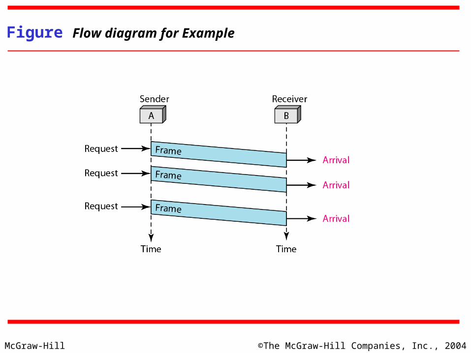
Figure shows an example of communication using this protocol. It is very simple. The sender sends a sequence of frames without even thinking about the receiver. To send three frames, three events occur at the sender site and three events at the receiver site.
Example
McGraw-Hill ©The McGraw-Hill Companies, Inc., 2004
Figure Flow diagram for Example
McGraw-Hill ©The McGraw-Hill Companies, Inc., 2004
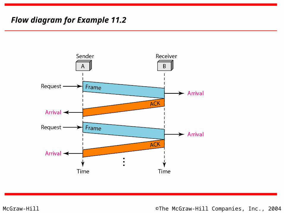
Figure shows an example of communication using this protocol. It is still very simple. The sender sends one frame and waits for feedback from the receiver. When the ACK arrives, the sender sends the next frame. Note that sending two frames in the protocol involves the sender in four events and the receiver in two events.
Example stop and wait protocol
McGraw-Hill ©The McGraw-Hill Companies, Inc., 2004
Flow diagram for Example 11.2
McGraw-Hill ©The McGraw-Hill Companies, Inc., 2004
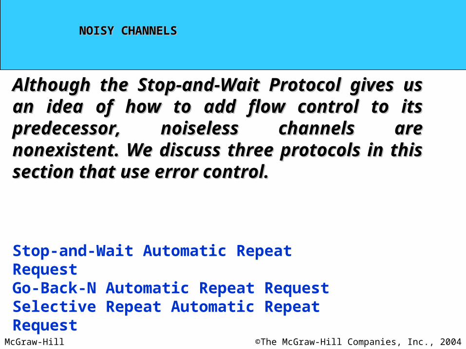
NOISY CHANNELSNOISY CHANNELS
Although the Stop-and-Wait Protocol gives us an idea Although the Stop-and-Wait Protocol gives us an idea of how to add flow control to its predecessor, noiseless of how to add flow control to its predecessor, noiseless channels are nonexistent. We discuss three protocols channels are nonexistent. We discuss three protocols in this section that use error control.in this section that use error control.
Stop-and-Wait Automatic Repeat RequestGo-Back-N Automatic Repeat RequestSelective Repeat Automatic Repeat Request
McGraw-Hill ©The McGraw-Hill Companies, Inc., 2004
Stop-and-Wait ARQStop-and-Wait ARQ
Operation
Bidirectional Transmission
McGraw-Hill ©The McGraw-Hill Companies, Inc., 2004
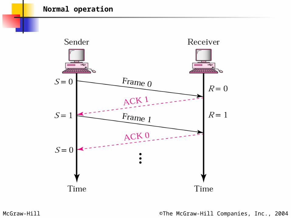
Normal operation
McGraw-Hill ©The McGraw-Hill Companies, Inc., 2004
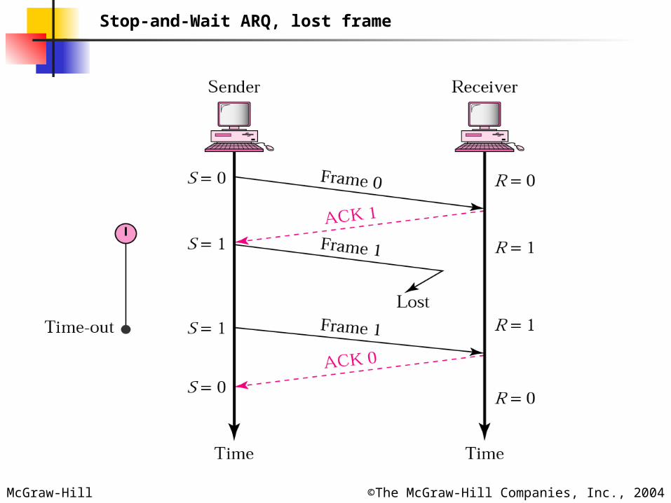
Stop-and-Wait ARQ, lost frame
McGraw-Hill ©The McGraw-Hill Companies, Inc., 2004
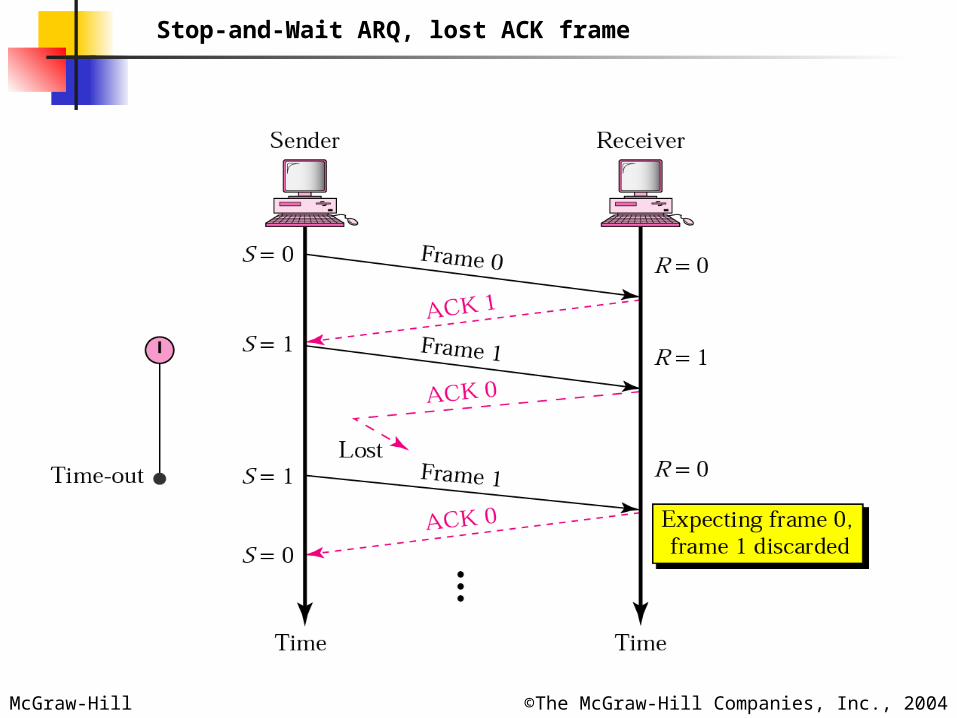
Stop-and-Wait ARQ, lost ACK frame
McGraw-Hill ©The McGraw-Hill Companies, Inc., 2004
In Stop-and-Wait ARQ, numbering In Stop-and-Wait ARQ, numbering frames prevents the retaining of frames prevents the retaining of
duplicate frames.duplicate frames.
NoteNote::
McGraw-Hill ©The McGraw-Hill Companies, Inc., 2004
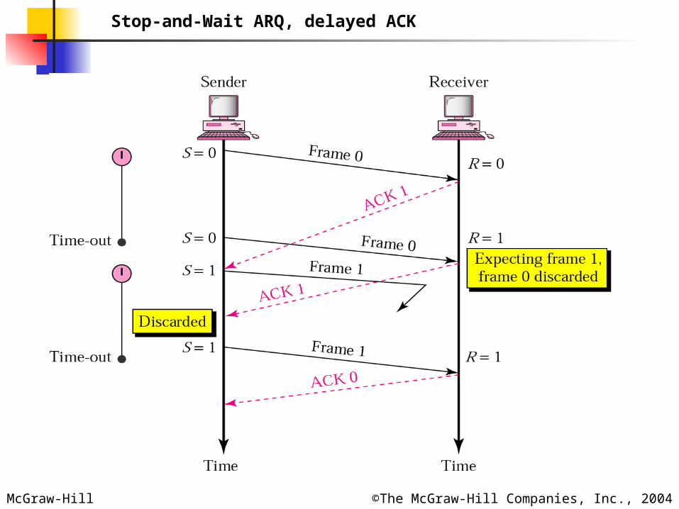
Stop-and-Wait ARQ, delayed ACK
McGraw-Hill ©The McGraw-Hill Companies, Inc., 2004
Numbered acknowledgments are Numbered acknowledgments are needed if an acknowledgment is needed if an acknowledgment is
delayed and the next frame is lost. delayed and the next frame is lost.
NoteNote::
McGraw-Hill ©The McGraw-Hill Companies, Inc., 2004
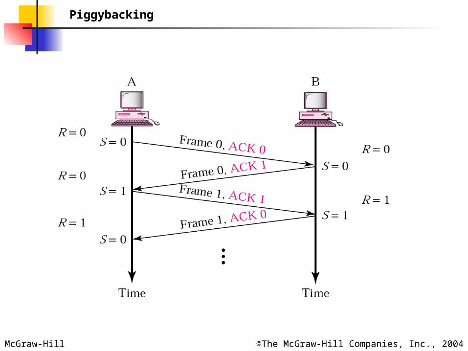
Piggybacking
McGraw-Hill ©The McGraw-Hill Companies, Inc., 2004
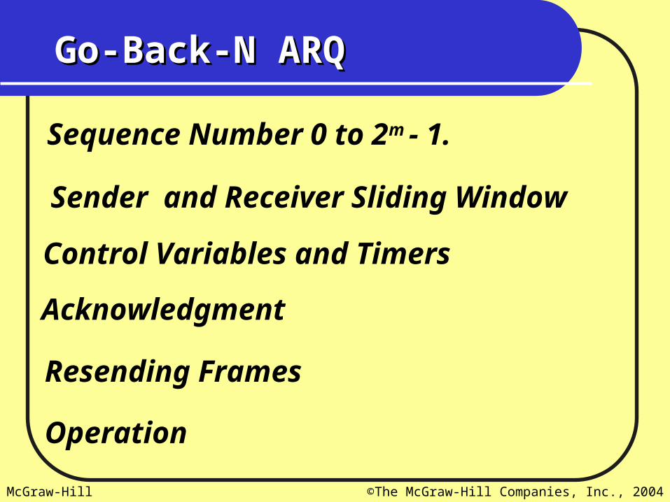
Go-Back-N ARQGo-Back-N ARQ
Sequence Number 0 to 2m - 1.
Sender and Receiver Sliding Window
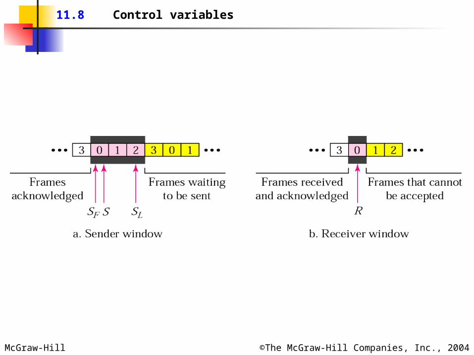
Control Variables and Timers
Acknowledgment
Resending Frames
Operation
McGraw-Hill ©The McGraw-Hill Companies, Inc., 2004
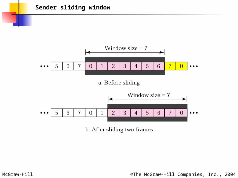
Sender sliding window
McGraw-Hill ©The McGraw-Hill Companies, Inc., 2004
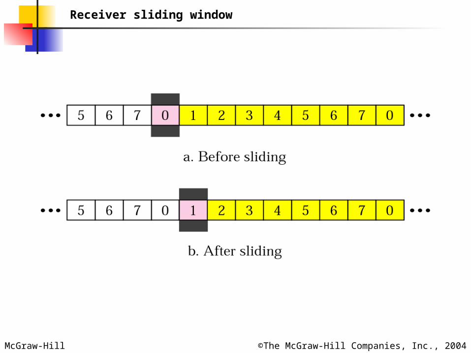
Receiver sliding window
McGraw-Hill ©The McGraw-Hill Companies, Inc., 2004
11.8 Control variables
McGraw-Hill ©The McGraw-Hill Companies, Inc., 2004
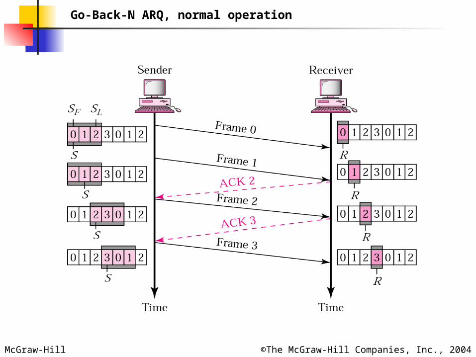
Go-Back-N ARQ, normal operation
McGraw-Hill ©The McGraw-Hill Companies, Inc., 2004
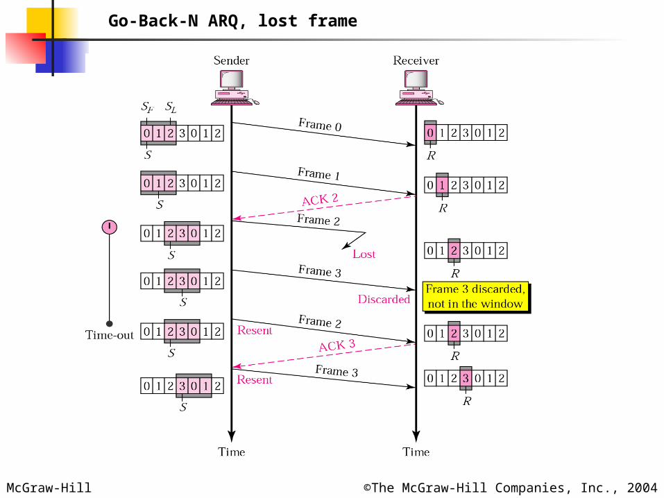
Go-Back-N ARQ, lost frame
McGraw-Hill ©The McGraw-Hill Companies, Inc., 2004
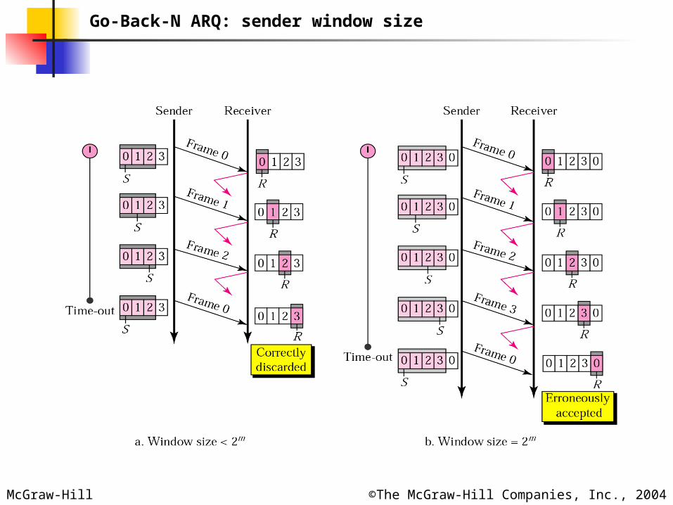
Go-Back-N ARQ: sender window size
McGraw-Hill ©The McGraw-Hill Companies, Inc., 2004
In Go-Back-N ARQ, the size of the In Go-Back-N ARQ, the size of the sender window must be less than 2sender window must be less than 2mm; ;
the size of the receiver window is the size of the receiver window is always 1.always 1.
NoteNote::
McGraw-Hill ©The McGraw-Hill Companies, Inc., 2004
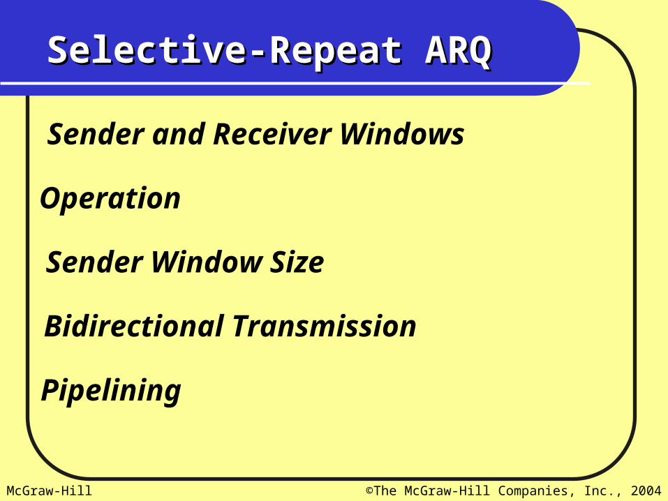
Selective-Repeat ARQSelective-Repeat ARQ
Sender and Receiver Windows
Operation
Sender Window Size
Bidirectional Transmission
Pipelining
McGraw-Hill ©The McGraw-Hill Companies, Inc., 2004
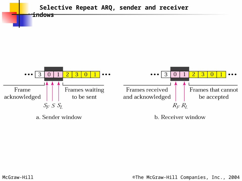
Selective Repeat ARQ, sender and receiver windows
McGraw-Hill ©The McGraw-Hill Companies, Inc., 2004
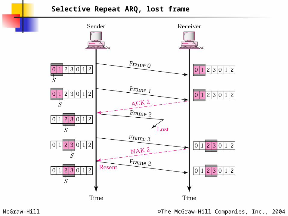
Selective Repeat ARQ, lost frame

McGraw-Hill ©The McGraw-Hill Companies, Inc., 2004
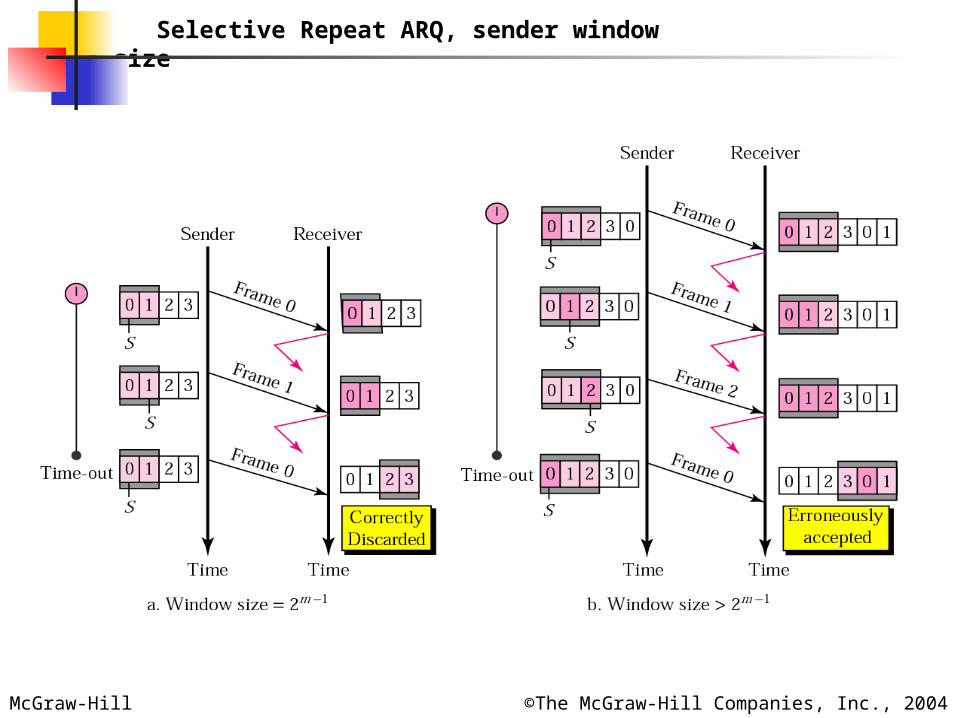
In Selective Repeat ARQ, the size of In Selective Repeat ARQ, the size of the sender and receiver window must the sender and receiver window must
be at most one-half of 2be at most one-half of 2mm. .
NoteNote::
McGraw-Hill ©The McGraw-Hill Companies, Inc., 2004
Selective Repeat ARQ, sender window size
McGraw-Hill ©The McGraw-Hill Companies, Inc., 2004
HDLCHDLC
High-level Data Link Control (HDLC) is a bit-oriented protocol for communication over point-to-point and multipoint links.Configurations and Transfer Modes:HDLC provides two common transfer modes that can be used in different configurations:normal response mode (NRM) and asynchronous balanced mode (ABM).
McGraw-Hill ©The McGraw-Hill Companies, Inc., 2004
NRM
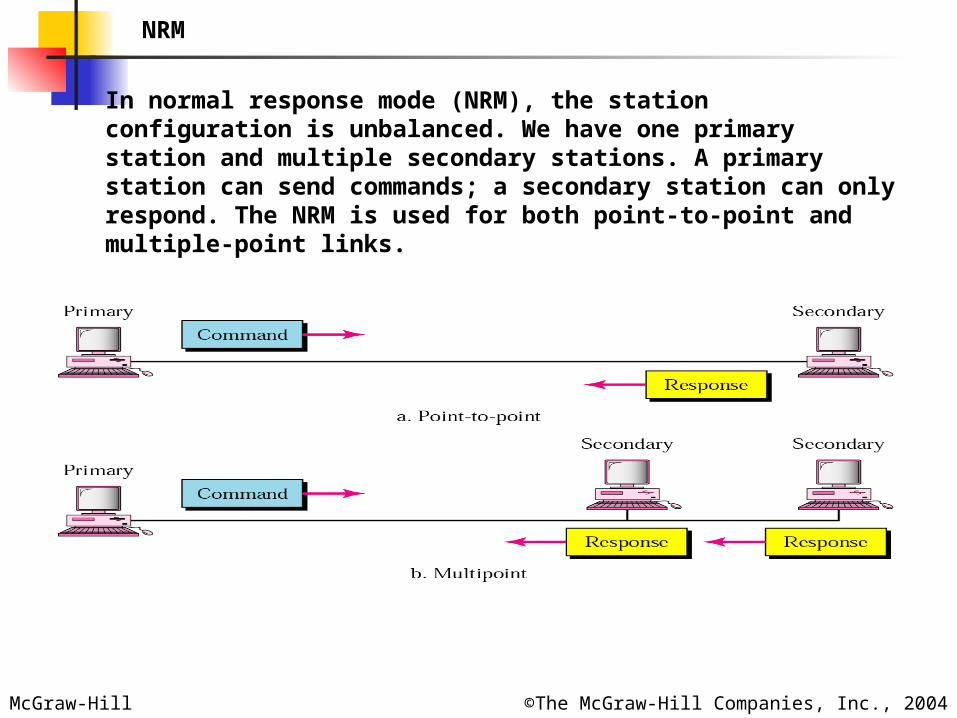
In normal response mode (NRM), the station configuration is unbalanced. We have one primary station and multiple secondary stations. A primary station can send commands; a secondary station can only respond. The NRM is used for both point-to-point and multiple-point links.
McGraw-Hill ©The McGraw-Hill Companies, Inc., 2004
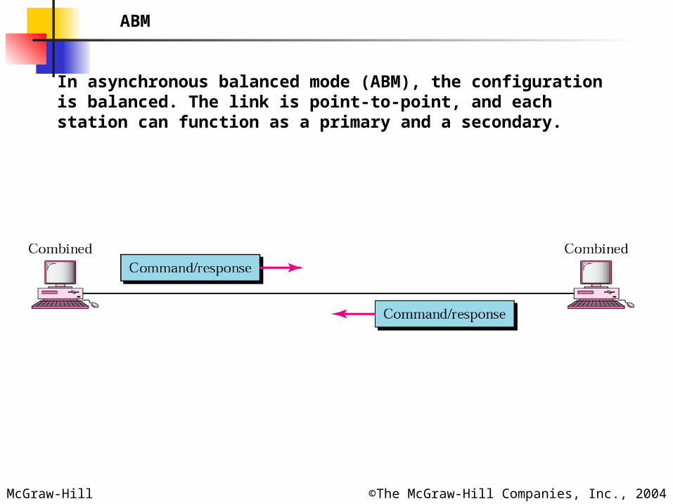
ABM
In asynchronous balanced mode (ABM), the configuration is balanced. The link is point-to-point, and each station can function as a primary and a secondary.
McGraw-Hill ©The McGraw-Hill Companies, Inc., 2004
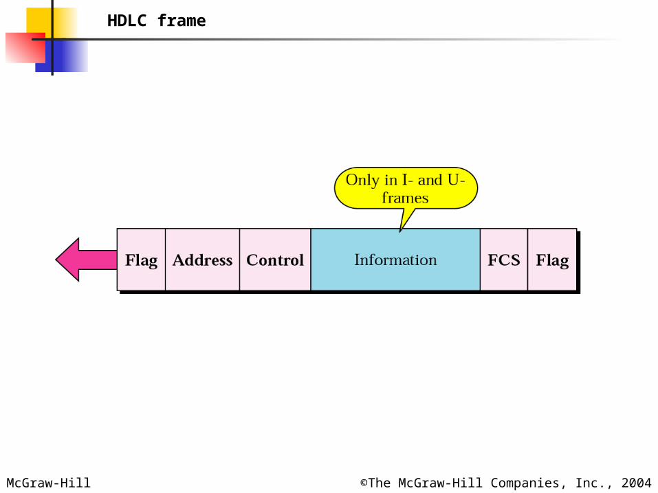
HDLC frame
McGraw-Hill ©The McGraw-Hill Companies, Inc., 2004
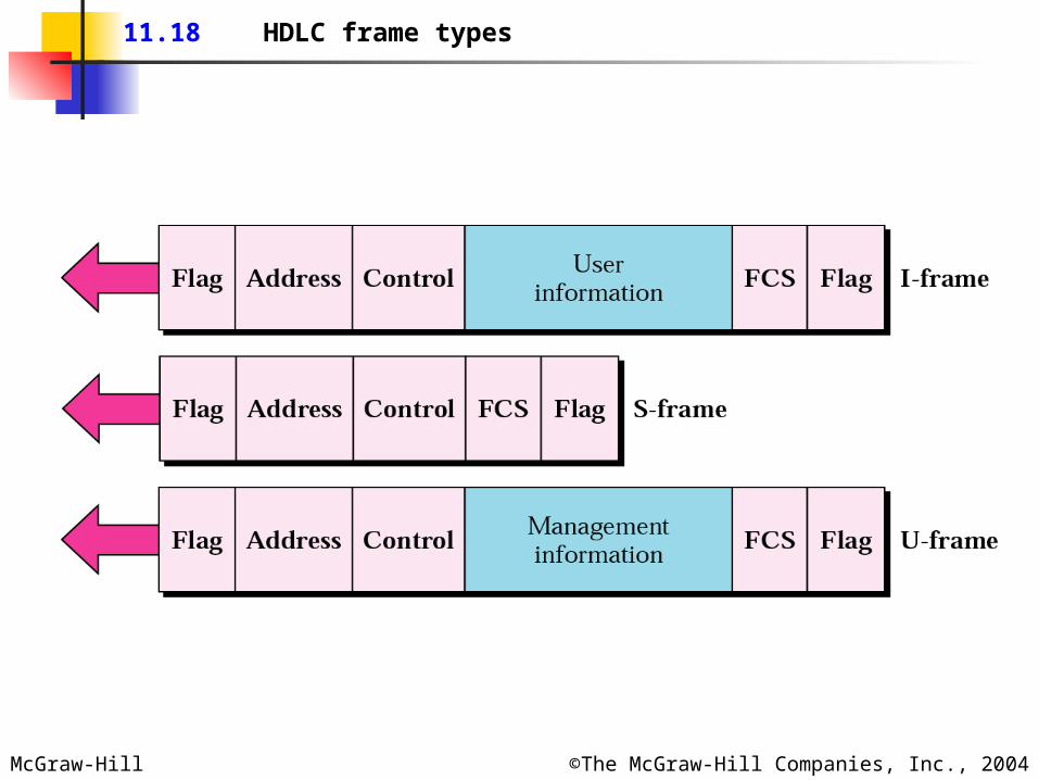
11.18 HDLC frame types
McGraw-Hill ©The McGraw-Hill Companies, Inc., 2004
McGraw-Hill ©The McGraw-Hill Companies, Inc., 2004
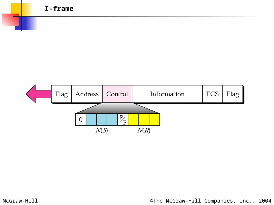
I-frame
McGraw-Hill ©The McGraw-Hill Companies, Inc., 2004
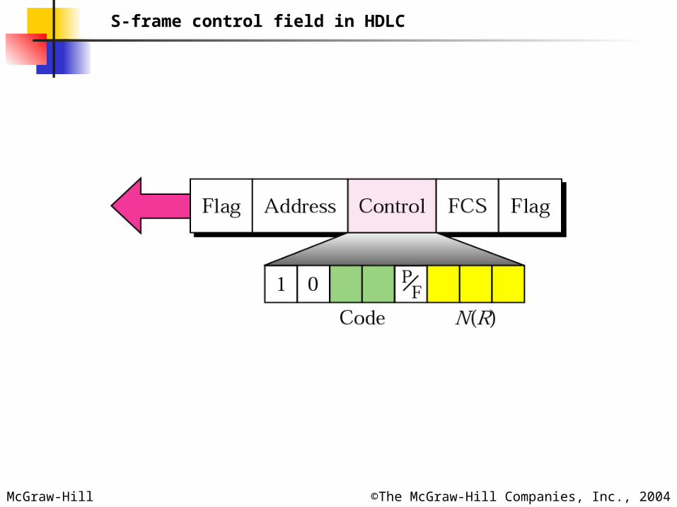
S-frame control field in HDLC
McGraw-Hill ©The McGraw-Hill Companies, Inc., 2004
McGraw-Hill ©The McGraw-Hill Companies, Inc., 2004
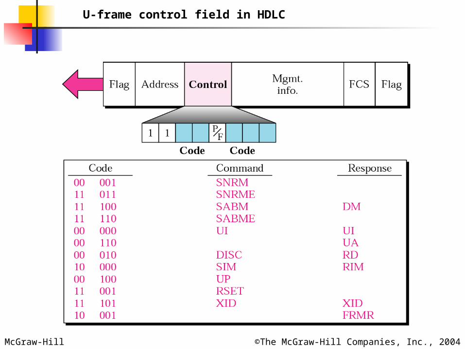
U-frame control field in HDLC
McGraw-Hill ©The McGraw-Hill Companies, Inc., 2004
Bit stuffing is the process of adding Bit stuffing is the process of adding one extra 0 whenever there are five one extra 0 whenever there are five
consecutive 1s in the data so that the consecutive 1s in the data so that the receiver does not mistake the receiver does not mistake the
data for a flag.data for a flag.
NoteNote::
McGraw-Hill ©The McGraw-Hill Companies, Inc., 2004
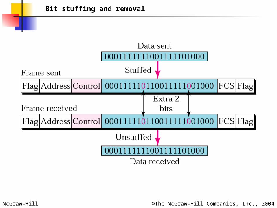
Bit stuffing and removal
McGraw-Hill ©The McGraw-Hill Companies, Inc., 2004
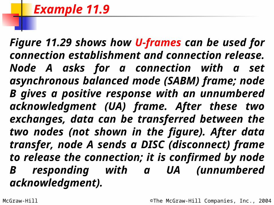
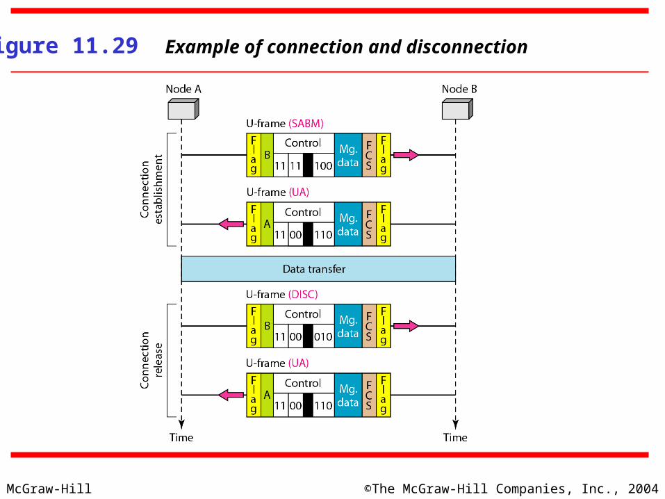
Figure 11.29 shows how U-frames can be used for connection establishment and connection release. Node A asks for a connection with a set asynchronous balanced mode (SABM) frame; node B gives a positive response with an unnumbered acknowledgment (UA) frame. After these two exchanges, data can be transferred between the two nodes (not shown in the figure). After data transfer, node A sends a DISC (disconnect) frame to release the connection; it is confirmed by node B responding with a UA (unnumbered acknowledgment).
Example 11.9
McGraw-Hill ©The McGraw-Hill Companies, Inc., 2004
Figure 11.29 Example of connection and disconnection
McGraw-Hill ©The McGraw-Hill Companies, Inc., 2004
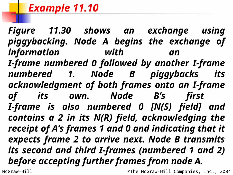
Figure 11.30 shows an exchange using piggybacking. Node A begins the exchange of information with an I-frame numbered 0 followed by another I-frame numbered 1. Node B piggybacks its acknowledgment of both frames onto an I-frame of its own. Node B’s first I-frame is also numbered 0 [N(S) field] and contains a 2 in its N(R) field, acknowledging the receipt of A’s frames 1 and 0 and indicating that it expects frame 2 to arrive next. Node B transmits its second and third I-frames (numbered 1 and 2) before accepting further frames from node A.
Example 11.10
McGraw-Hill ©The McGraw-Hill Companies, Inc., 2004
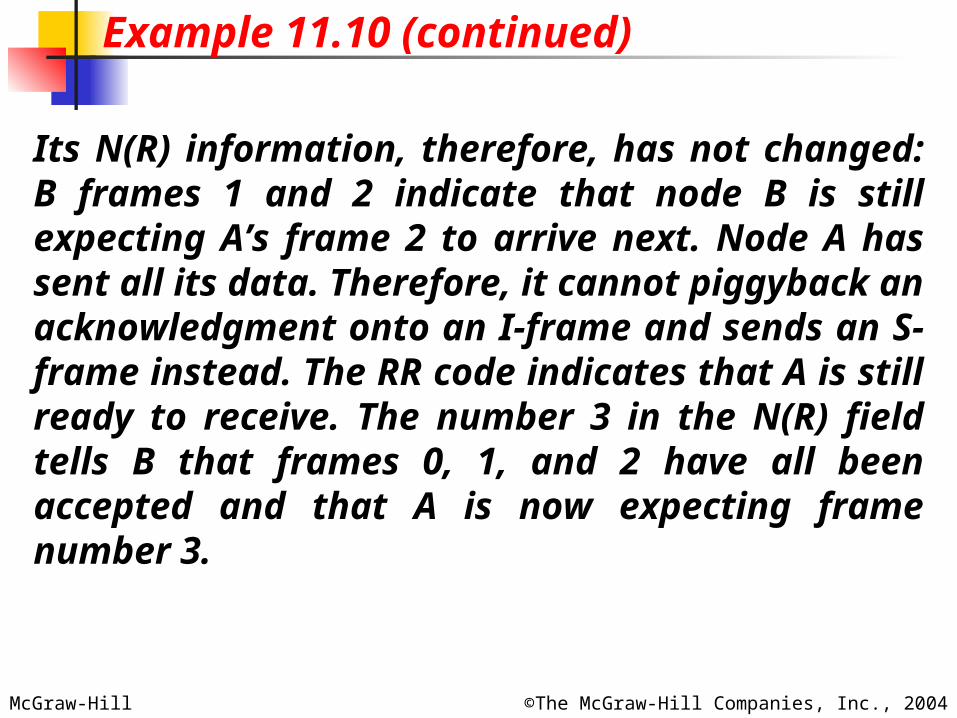
Its N(R) information, therefore, has not changed: B frames 1 and 2 indicate that node B is still expecting A’s frame 2 to arrive next. Node A has sent all its data. Therefore, it cannot piggyback an acknowledgment onto an I-frame and sends an S-frame instead. The RR code indicates that A is still ready to receive. The number 3 in the N(R) field tells B that frames 0, 1, and 2 have all been accepted and that A is now expecting frame number 3.
Example 11.10 (continued)
McGraw-Hill ©The McGraw-Hill Companies, Inc., 2004
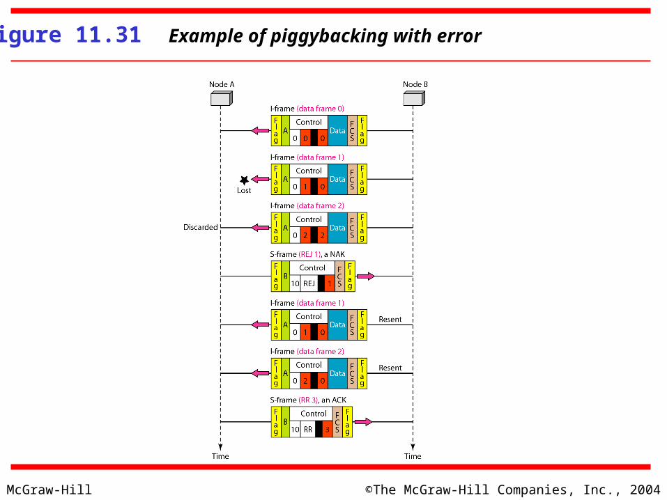
Figure 11.31 Example of piggybacking with error