Embed Size (px)
Citation preview
© 2008 Microchip Technology Inc. DS51777A
MCP3909 ADC Evaluation Board
for 16-Bit MCUs User’s Guide
DS51777A-page ii © 2008 Microchip Technology Inc.
Information contained in this publication regarding deviceapplications and the like is provided only for your convenienceand may be superseded by updates. It is your responsibility toensure that your application meets with your specifications.MICROCHIP MAKES NO REPRESENTATIONS ORWARRANTIES OF ANY KIND WHETHER EXPRESS ORIMPLIED, WRITTEN OR ORAL, STATUTORY OROTHERWISE, RELATED TO THE INFORMATION,INCLUDING BUT NOT LIMITED TO ITS CONDITION,QUALITY, PERFORMANCE, MERCHANTABILITY ORFITNESS FOR PURPOSE. Microchip disclaims all liabilityarising from this information and its use. Use of Microchipdevices in life support and/or safety applications is entirely atthe buyer’s risk, and the buyer agrees to defend, indemnify andhold harmless Microchip from any and all damages, claims,suits, or expenses resulting from such use. No licenses areconveyed, implicitly or otherwise, under any Microchipintellectual property rights.
Trademarks
The Microchip name and logo, the Microchip logo, Accuron, dsPIC, KEELOQ, KEELOQ logo, MPLAB, PIC, PICmicro, PICSTART, rfPIC, SmartShunt and UNI/O are registered trademarks of Microchip Technology Incorporated in the U.S.A. and other countries.
FilterLab, Linear Active Thermistor, MXDEV, MXLAB, SEEVAL, SmartSensor and The Embedded Control Solutions Company are registered trademarks of Microchip Technology Incorporated in the U.S.A.
Analog-for-the-Digital Age, Application Maestro, CodeGuard, dsPICDEM, dsPICDEM.net, dsPICworks, dsSPEAK, ECAN, ECONOMONITOR, FanSense, In-Circuit Serial Programming, ICSP, ICEPIC, Mindi, MiWi, MPASM, MPLAB Certified logo, MPLIB, MPLINK, mTouch, PICkit, PICDEM, PICDEM.net, PICtail, PIC32 logo, PowerCal, PowerInfo, PowerMate, PowerTool, REAL ICE, rfLAB, Select Mode, Total Endurance, WiperLock and ZENA are trademarks of Microchip Technology Incorporated in the U.S.A. and other countries.
SQTP is a service mark of Microchip Technology Incorporated in the U.S.A.
All other trademarks mentioned herein are property of their respective companies.
© 2008, Microchip Technology Incorporated, Printed in the U.S.A., All Rights Reserved.
Printed on recycled paper.
Note the following details of the code protection feature on Microchip devices:• Microchip products meet the specification contained in their particular Microchip Data Sheet.
• Microchip believes that its family of products is one of the most secure families of its kind on the market today, when used in the intended manner and under normal conditions.
• There are dishonest and possibly illegal methods used to breach the code protection feature. All of these methods, to our knowledge, require using the Microchip products in a manner outside the operating specifications contained in Microchip’s Data Sheets. Most likely, the person doing so is engaged in theft of intellectual property.
• Microchip is willing to work with the customer who is concerned about the integrity of their code.
• Neither Microchip nor any other semiconductor manufacturer can guarantee the security of their code. Code protection does not mean that we are guaranteeing the product as “unbreakable.”
Code protection is constantly evolving. We at Microchip are committed to continuously improving the code protection features of ourproducts. Attempts to break Microchip’s code protection feature may be a violation of the Digital Millennium Copyright Act. If such actsallow unauthorized access to your software or other copyrighted work, you may have a right to sue for relief under that Act.
Microchip received ISO/TS-16949:2002 certification for its worldwide headquarters, design and wafer fabrication facilities in Chandler and Tempe, Arizona; Gresham, Oregon and design centers in California and India. The Company’s quality system processes and procedures are for its PIC® MCUs and dsPIC® DSCs, KEELOQ® code hopping devices, Serial EEPROMs, microperipherals, nonvolatile memory and analog products. In addition, Microchip’s quality system for the design and manufacture of development systems is ISO 9001:2000 certified.
MCP3909 ADC EVALUATION BOARDFOR 16-BIT MCUs USER’S GUIDE
© 2008 Microchip Technology Inc. DS51777A-page iii
Table of Contents
Preface ........................................................................................................................... 1Introduction............................................................................................................ 1Document Layout .................................................................................................. 1Conventions Used in this Guide ............................................................................ 2Recommended Reading........................................................................................ 3The Microchip Web Site ........................................................................................ 3Customer Support ................................................................................................. 3Document Revision History ................................................................................... 3
Chapter 1. Hardware Description1.1 Overview ........................................................................................................ 51.2 PIM Module / MCP3909 Connection and Peripheral Usage Overview .......... 71.3 MCP3909 Delta-Sigma Sampling / MCLK Options ........................................ 81.4 Analog Input Structure .................................................................................... 91.5 Universal Serial Bus (USB) ............................................................................ 9
Chapter 2. Firmware2.1 DSPIC33 Firmware Description ................................................................... 112.2 Display Mode Control - SW2 ........................................................................ 132.3 Sampling Speed Rate Control - SW3 ........................................................... 132.4 Data Acquisition ........................................................................................... 132.5 Data Transmission ....................................................................................... 15
Chapter 3. MCP3909 PC Software Tool3.1 Software Overview ....................................................................................... 173.2 Setting the Sample Rate .............................................................................. 183.3 Connectivity, Recording Length and Calibration of Data .............................. 183.4 Scope Plot Window - Time Domain Analysis ............................................... 183.5 Histogram Window - Noise Analysis ............................................................ 193.6 FFT Window - Frequency Domain Analysis ................................................. 193.7 Auxiliary Data Window ................................................................................. 19
MCP3909 ADC Evaluation Board for 16-Bit MCUs User’s Guide
DS51777A-page iv © 2008 Microchip Technology Inc.
Appendix A. Schematics and LayoutsA.1 Introduction .................................................................................................. 21A.2 Schematic - Analog ...................................................................................... 22A.3 Schematic - LCD And UART ....................................................................... 23A.4 Schematic - USB And Memory .................................................................... 24A.5 Schematic - Microcontroller (MCU) .............................................................. 25A.6 Schematic - PIM Module .............................................................................. 26A.7 Schematic - Power ....................................................................................... 27A.8 Board - Top Trace and Top Silk ................................................................... 28A.9 Board - Bottom Trace and Bottom Silk ........................................................ 28A.10 Board - Layer #2 VDD ................................................................................ 29A.11 Board - Layer #3 GND ............................................................................... 29A.12 Board -Top Silk and Pads .......................................................................... 30A.13 Board - Bottom Silk and Pads .................................................................... 30
Appendix B. Bill of Materials (BOM)Worldwide Sales and Service .....................................................................................34
MCP3909 ADC EVALUATION BOARDFOR 16-BIT MCUs USER’S GUIDE
© 2008 Microchip Technology Inc. DS51777A-page 1
Preface
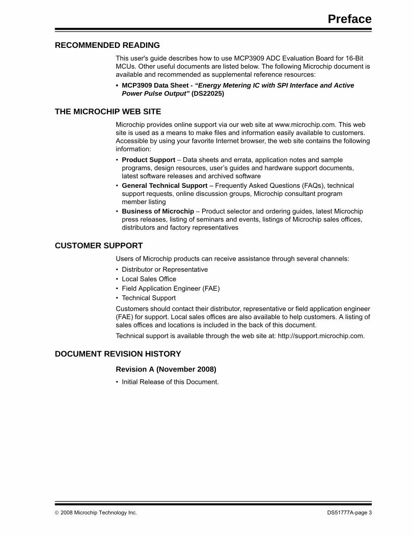
INTRODUCTIONThis chapter contains general information that will be useful to know before using the MCP3909 ADC Evaluation Board for 16-Bit MCUs. Items discussed in this chapter include:• Document Layout• Conventions Used in this Guide• Recommended Reading• The Microchip Web Site• Customer Support• Document Revision History
DOCUMENT LAYOUTThis document describes how to use the MCP3909 ADC Evaluation Board for 16-Bit MCUs as a development tool to emulate and debug firmware on a target board. The manual layout is as follows:• Chapter 1. “Hardware Description”– Provides important information about the
MCP3909 ADC Evaluation Board for 16-Bit MCUs hardware.• Chapter 2. “Firmware”– Describes the MCP3909 ADC Evaluation Board for
16-Bit MCUs firmware. • Chapter 3. “MCP3909 PC Software Tool” – Provides detailed information about
board’s PC software tool.• Appendix A. “Schematics and Layouts”– Shows the schematic and board
layouts for the MCP3909 ADC Evaluation Board for 16-Bit MCUs.• Appendix B. “Bill of Materials (BOM)” – Lists the parts used to build the
MCP3909 ADC Evaluation Board for 16-Bit MCUs.
NOTICE TO CUSTOMERS
All documentation becomes dated, and this manual is no exception. Microchip tools and documentation are constantly evolving to meet customer needs, so some actual dialogs and/or tool descriptions may differ from those in this document. Please refer to our web site (www.microchip.com) to obtain the latest documentation available.
Documents are identified with a “DS” number. This number is located on the bottom of each page, in front of the page number. The numbering convention for the DS number is “DSXXXXXA”, where “XXXXX” is the document number and “A” is the revision level of the document.
For the most up-to-date information on development tools, see the MPLAB® IDE on-line help. Select the Help menu, and then Topics to open a list of available on-line help files.

MCP3909 ADC Evaluation Board for 16-Bit MCUs User’s Guide
DS51777A-page 2 © 2008 Microchip Technology Inc.
CONVENTIONS USED IN THIS GUIDEThis manual uses the following documentation conventions:
DOCUMENTATION CONVENTIONSDescription Represents Examples
Arial font:Italic characters Referenced books MPLAB® IDE User’s Guide
Emphasized text ...is the only compiler...Initial caps A window the Output window
A dialog the Settings dialogA menu selection select Enable Programmer
Quotes A field name in a window or dialog
“Save project before build”
Underlined, italic text with right angle bracket
A menu path File>Save
Bold characters A dialog button Click OKA tab Click the Power tab
N‘Rnnnn A number in verilog format, where N is the total number of digits, R is the radix and n is a digit.
4‘b0010, 2‘hF1
Text in angle brackets < > A key on the keyboard Press <Enter>, <F1>Courier New font:Plain Courier New Sample source code #define START
Filenames autoexec.batFile paths c:\mcc18\h
Keywords _asm, _endasm, static
Command-line options -Opa+, -Opa-Bit values 0, 1
Constants 0xFF, ‘A’
Italic Courier New A variable argument file.o, where file can be any valid filename
Square brackets [ ] Optional arguments mcc18 [options] file [options]
Curly brackets and pipe character: { | }
Choice of mutually exclusive arguments; an OR selection
errorlevel {0|1}
Ellipses... Replaces repeated text var_name [, var_name...]
Represents code supplied by user
void main (void){ ...}
Preface
© 2008 Microchip Technology Inc. DS51777A-page 3
RECOMMENDED READINGThis user's guide describes how to use MCP3909 ADC Evaluation Board for 16-Bit MCUs. Other useful documents are listed below. The following Microchip document is available and recommended as supplemental reference resources:• MCP3909 Data Sheet - “Energy Metering IC with SPI Interface and Active
Power Pulse Output” (DS22025)
THE MICROCHIP WEB SITEMicrochip provides online support via our web site at www.microchip.com. This web site is used as a means to make files and information easily available to customers. Accessible by using your favorite Internet browser, the web site contains the following information:• Product Support – Data sheets and errata, application notes and sample
programs, design resources, user’s guides and hardware support documents, latest software releases and archived software
• General Technical Support – Frequently Asked Questions (FAQs), technical support requests, online discussion groups, Microchip consultant program member listing
• Business of Microchip – Product selector and ordering guides, latest Microchip press releases, listing of seminars and events, listings of Microchip sales offices, distributors and factory representatives
CUSTOMER SUPPORTUsers of Microchip products can receive assistance through several channels:• Distributor or Representative• Local Sales Office• Field Application Engineer (FAE)• Technical SupportCustomers should contact their distributor, representative or field application engineer (FAE) for support. Local sales offices are also available to help customers. A listing of sales offices and locations is included in the back of this document.Technical support is available through the web site at: http://support.microchip.com.
DOCUMENT REVISION HISTORY
Revision A (November 2008)• Initial Release of this Document.

MCP3909 ADC Evaluation Board for 16-Bit MCUs User’s Guide
DS51777A-page 4 © 2008 Microchip Technology Inc.
NOTES:
MCP3909 ADC EVALUATION BOARDFOR 16-BIT MCUs USER’S GUIDE
© 2008 Microchip Technology Inc. DS51777A-page 5
Chapter 1. Hardware Description
1.1 OVERVIEWThe MCP3909 ADC Evaluation Board for 16-Bit MCUs system provides the ability to evaluate the performance of the MCP3909 dual channel ADC. It also provides a devel-opment platform for 16-bit PIC based applications, using existing 100-pin PIM systems compatible with the Explorer-16 and other high pincount PIC demo boards. The system comes with programmed PIC24FJ128GA010 and dsPIC33FJ256GP710 PIM modules that communicate both to on-board LCD and a LabView GUI for both in-circuit and PC signal processing.
1.1.1 Feature Highlights• Dual 16-bit ADC MCP3909 output display using Serial communication to
PC Software Interface• Simultaneous 15 ksps at 81 dB SINAD performance on dual 16-Bit MCP3909
channels• Spectral Analysis using DFT dsPIC33F calculations, resolution of TBDAH• System and ADC performance analysis through graphical PC tools showing Noise
Histogram, Frequency Domain (FFT), Time domain scope plot, and statistical numerical analysis
• Robust hardware design with analog grounding and analog/digital separation, allowing low noise evaluation of MCP3909 devices. Separate power supplies and power planes - 4 layer board
• Pigtail Plus connectors for Explorer-16 daughter board compatibility

MCP3909 ADC Evaluation Board for 16-Bit MCUs User’s Guide
DS51777A-page 6 © 2008 Microchip Technology Inc.
FIGURE 1-1: Evaluation Board Block Diagram.
PIM (100-PIN)PIC18F86J65
MCP3909
EX
T +5
V
SRAM
EXT +5V+9V INUSB
CH0+
CH0-GND
CH1+
CH1-GND
+G-
+G-
+-
MCP3909 ADC Evaluation Board for 16-bit MCU
PIM RESET SW2 SW3 SW4
PIC18 AUX I/O PIC18 EXTERNAL I/O
MCP3909Digital I/O
9V EXT. IN
USB
PWR LED(Blue)
RA9RA10
HFOUT
+5VREG
+3VREG
PIC
tail
Plu
s
PIC
18 IC
D
PIC
18 IC
DSerial Connector
Hardware Description
© 2008 Microchip Technology Inc. DS51777A-page 7
1.2 PIM MODULE / MCP3909 CONNECTION AND PERIPHERAL USAGE OVERVIEW
The MCP3909 ADC Evaluation Board for 16-Bit MCUs contains a 100-pin PIM socket compatible with Microchip’s PIM modules. The system comes with 2 PIM modules: the PIC24FJ128GA010 and dsPIC33FJ256GA710. A complete description of the firmware programmed with these two modules see in Chapter 1. “Hardware Description”.
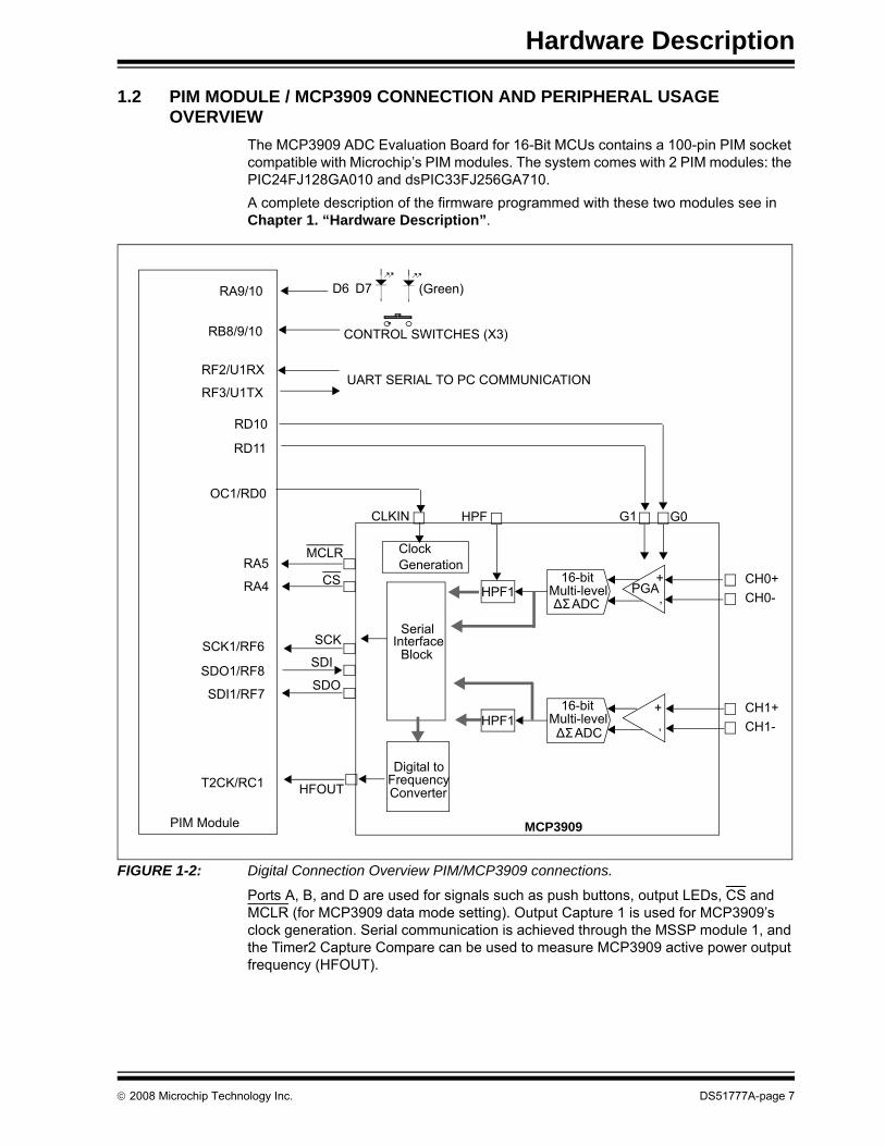
FIGURE 1-2: Digital Connection Overview PIM/MCP3909 connections.
Ports A, B, and D are used for signals such as push buttons, output LEDs, CS and MCLR (for MCP3909 data mode setting). Output Capture 1 is used for MCP3909’s clock generation. Serial communication is achieved through the MSSP module 1, and the Timer2 Capture Compare can be used to measure MCP3909 active power output frequency (HFOUT).
CONTROL SWITCHES (X3)
16-bit
ΔΣ ADC
+‚
CH0+CH0-
+‚
CH1+CH1-
HPF1
G0G1HPF
Multi-level
16-bit
ΔΣ ADCMulti-levelHPF1
PGA
MCLR
MCP3909
CS
SCK
SDI
SDO
RA5
RA4
SCK1/RF6
SDO1/RF8
SDI1/RF7
RB8/9/10
RD11
RD10
PIM Module
Serial Interface
Block
HFOUTT2CK/RC1Digital to
FrequencyConverter
CLKIN
OC1/RD0
ClockGeneration
RA9/10 D6 D7 (Green)
RF3/U1TX
RF2/U1RXUART SERIAL TO PC COMMUNICATION
MCP3909 ADC Evaluation Board for 16-Bit MCUs User’s Guide
DS51777A-page 8 © 2008 Microchip Technology Inc.
1.3 MCP3909 DELTA-SIGMA SAMPLING / MCLK OPTIONSThe MCP3909 device is an ADC with a second order modulator and a third order sinc filter. This Delta-Sigma A/D converter has an oversampling ratio of 64. The CLKIN pin of the MCP3909 is the oversampling clock (MCLK) input and the output data rate is MCLK/256. The MCP3909 ADC Evaluation Board for 16-Bit MCUs offers two different options for the MCP3909 master clock (MCLK).
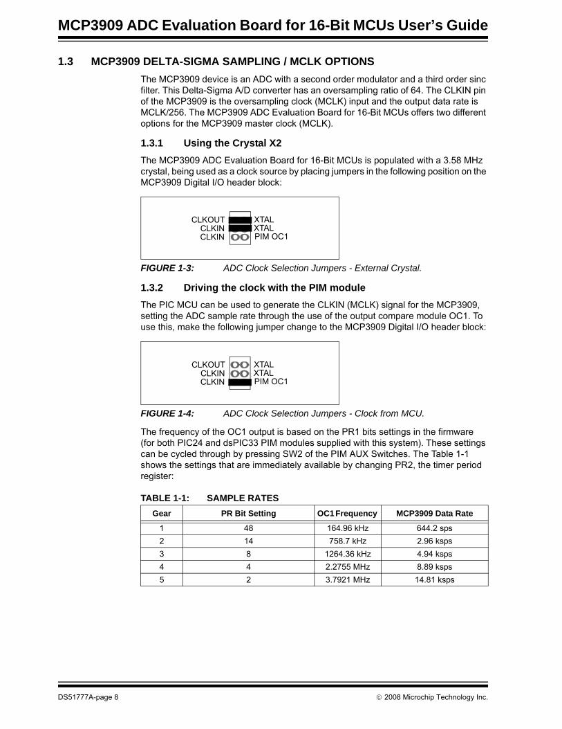
1.3.1 Using the Crystal X2The MCP3909 ADC Evaluation Board for 16-Bit MCUs is populated with a 3.58 MHz crystal, being used as a clock source by placing jumpers in the following position on the MCP3909 Digital I/O header block:
FIGURE 1-3: ADC Clock Selection Jumpers - External Crystal.
1.3.2 Driving the clock with the PIM moduleThe PIC MCU can be used to generate the CLKIN (MCLK) signal for the MCP3909, setting the ADC sample rate through the use of the output compare module OC1. To use this, make the following jumper change to the MCP3909 Digital I/O header block:
FIGURE 1-4: ADC Clock Selection Jumpers - Clock from MCU.
The frequency of the OC1 output is based on the PR1 bits settings in the firmware (for both PIC24 and dsPIC33 PIM modules supplied with this system). These settings can be cycled through by pressing SW2 of the PIM AUX Switches. The Table 1-1 shows the settings that are immediately available by changing PR2, the timer period register:
TABLE 1-1: SAMPLE RATESGear PR Bit Setting OC1 Frequency MCP3909 Data Rate
1 48 164.96 kHz 644.2 sps2 14 758.7 kHz 2.96 ksps3 8 1264.36 kHz 4.94 ksps4 4 2.2755 MHz 8.89 ksps5 2 3.7921 MHz 14.81 ksps
XTALXTALPIM OC1CLKIN
CLKINCLKOUT
XTALXTALPIM OC1CLKIN
CLKINCLKOUT
Hardware Description
© 2008 Microchip Technology Inc. DS51777A-page 9
1.4 ANALOG INPUT STRUCTURETwo differential input paths allow external signal sources to be easily connected to the MCP3909 input. Edge connectors P1 and P2 are 3-pin connectors that act as both crew type and clip on post connectors.
JP1 and JP2 can be used to force either channel from a differential to single-ended configuration. R3 and R4 (on CH0), and R1 and R2 (on CH2) act as locations for burden resistor connectors for any current transformer inputs.
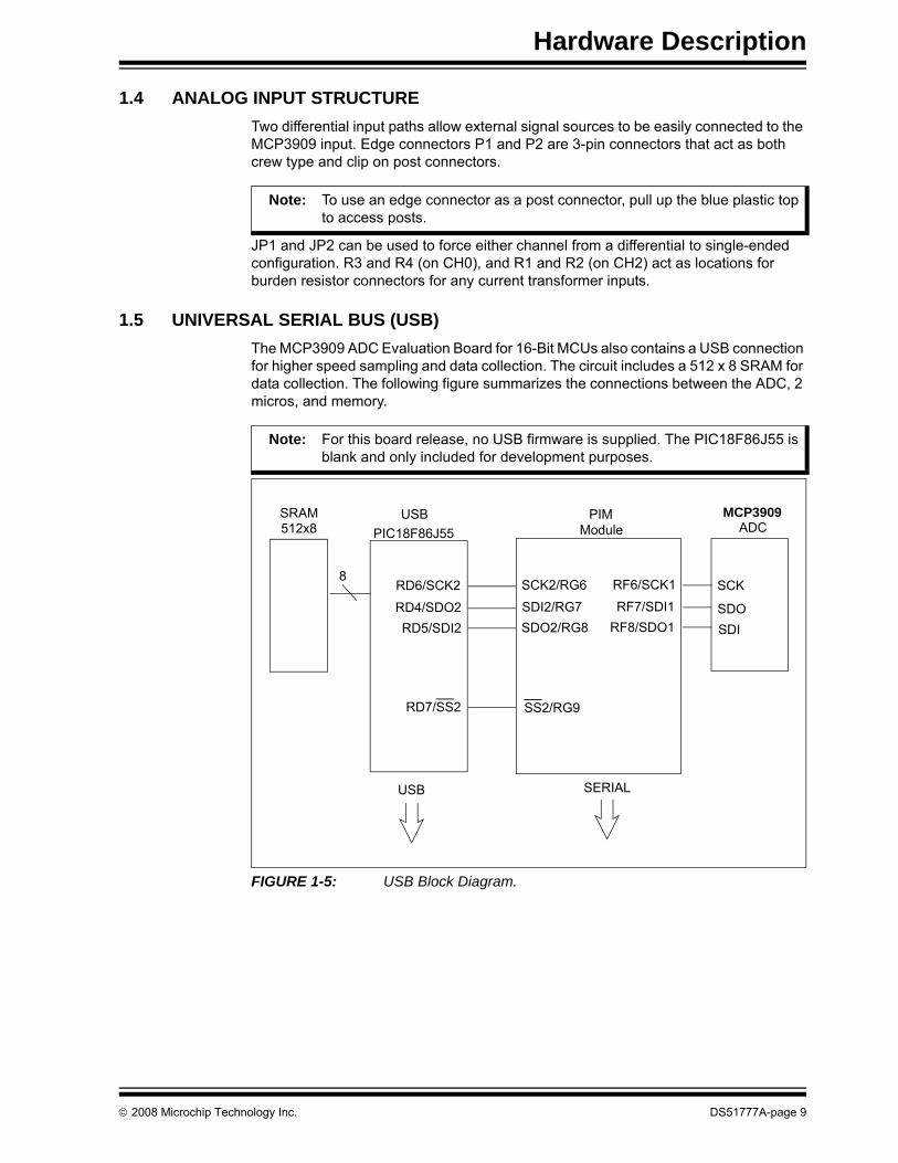
1.5 UNIVERSAL SERIAL BUS (USB)The MCP3909 ADC Evaluation Board for 16-Bit MCUs also contains a USB connection for higher speed sampling and data collection. The circuit includes a 512 x 8 SRAM for data collection. The following figure summarizes the connections between the ADC, 2 micros, and memory.
FIGURE 1-5: USB Block Diagram.
Note: To use an edge connector as a post connector, pull up the blue plastic top to access posts.
Note: For this board release, no USB firmware is supplied. The PIC18F86J55 is blank and only included for development purposes.
PIM
SCK2/RG6SDI2/RG7SDO2/RG8
Module
SS2/RG9
USB
RD6/SCK2RD4/SDO2RD5/SDI2
PIC18F86J55
RD7/SS2
ADC MCP3909
RF6/SCK1RF7/SDI1
RF8/SDO1
SCK
SDOSDI
USB SERIAL
512x8 SRAM
8

MCP3909 ADC Evaluation Board for 16-Bit MCUs User’s Guide
DS51777A-page 10 © 2008 Microchip Technology Inc.
NOTES:

MCP3909 ADC EVALUATION BOARDFOR 16-BIT MCUs USER’S GUIDE
© 2008 Microchip Technology Inc. DS51777A-page 11
Chapter 2. Firmware
2.1 DSPIC33 FIRMWARE DESCRIPTION
2.1.1 Reset and InitializationAfter reset, the code jumps to line 305 from main.c file, where the initialization routine is called: Initialization(). First, the nested interrupts are disabled. External interrupt 3 is enabled on the negative edge. Timer 2 is running on the Output Compare 1, being used to generate the clock for the MCP3909. In addition, some initial values are set up for the MCP3909 clock frequency.Timer 5 is enabled and set to generate an interrupt at compare mach; the time period between two interrupts is a few hundred milliseconds.
The SPI module is initialized and started, but the corresponding interrupt is not enabled. UART transmitter is initialized, but the corresponding interrupt is not enabled. Communication speed is set for 115200 baud. The UART receiver is not used.Pins with analogue alternate function are setup as digital-input outputs. Initial values for different variables are being set at the end of the initialization routine.Back in the void main() routine the nested interrupts are enabled. Then the routine that starts the MCP3909 is called: startMCP3909().
2.1.2 startMCP3909()During this routine the MCP3909 is put into a test mode, according to the MCP3909 data sheet. At the beginning CS and MCP3909 reset pins (MCLR) have high values. After a slight delay, MCLR is toggled low, and then the serial command b10100100 is sent to the device. This means that the ADC is placed into “Dual Channel Output PRE HPF1” mode. Then, a short positive pulse is sent to CS.
2.1.3 Main()In the main() file, the LCD will display the samples values.At this point, the Main routine will enter an infinite loop. All the other tasks are being done during the interrupt routines.
2.1.4 Timer 5 Compare Mach InterruptAll events that don't need to take place to a repeated, constant period of time are processed during this interrupt. One event that is happening at the time of this routine is the blinking of LED D7 - as a life sign for the system. This routine is monitoring the buttons state (pressed or not pressed), and also counts how many times each of them have been pressed.
Note: The time period can be changed from PR5 register.

MCP3909 ADC Evaluation Board for 16-Bit MCUs User’s Guide
DS51777A-page 12 © 2008 Microchip Technology Inc.
FIGURE 2-1: LCD Control Flowchart.
START
Initialization
LCD: “Samples Value”
SW2 pressed?
SW2 pressed once
Copy CH1 samples in signal[] buffer;Compute FFT;
Indicate on LCD FFT results: magnitude and frequency;
Copy CH0 samples in signal[] buffer;Compute FFT;
Indicate on LCD FFT results: magnitude and frequency;
YES
SW2 pressed twice
NO
YES
NO
Copy CH0 samples in signal[] buffer;Compute Autocorrelation function;
Indicate on the LCD the signal frequency and the index of maximum value
SW2 pressed3rd time
YES
NO
SW3 pressed?
SW3 pressed once
Set sampling speed: gear 2
Set sampling speed: gear 1YES
SW3 pressed twice
NO
YES
NO
Set sampling speed: gear 3SW3 pressed3rd time
Adjust value of: But2Cont NO
YES
Adjust value of: But1Cont
YES NO
YES
NO
Set sampling speed: gear 4SW3 pressed4th time
NO
Set sampling speed: gear 5SW3 pressed5th time
NO
YES
YES
Firmware
© 2008 Microchip Technology Inc. DS51777A-page 13
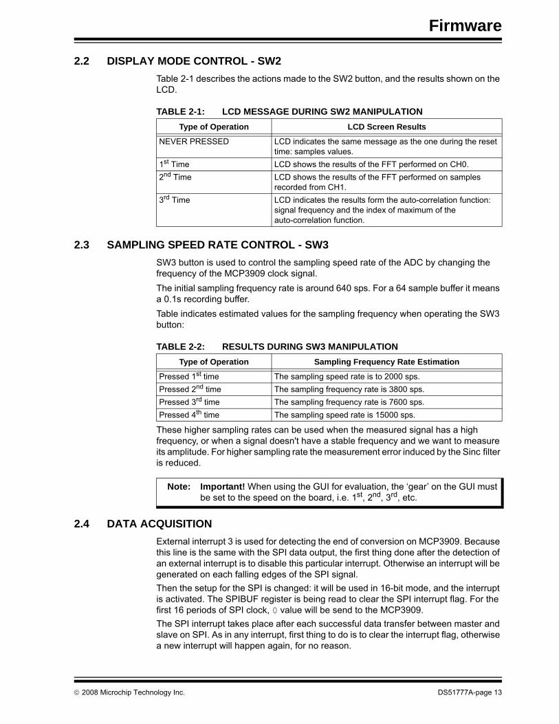
2.2 DISPLAY MODE CONTROL - SW2Table 2-1 describes the actions made to the SW2 button, and the results shown on the LCD.
TABLE 2-1: LCD MESSAGE DURING SW2 MANIPULATION
2.3 SAMPLING SPEED RATE CONTROL - SW3SW3 button is used to control the sampling speed rate of the ADC by changing the frequency of the MCP3909 clock signal.The initial sampling frequency rate is around 640 sps. For a 64 sample buffer it means a 0.1s recording buffer.Table indicates estimated values for the sampling frequency when operating the SW3 button:
TABLE 2-2: RESULTS DURING SW3 MANIPULATION
These higher sampling rates can be used when the measured signal has a high frequency, or when a signal doesn't have a stable frequency and we want to measure its amplitude. For higher sampling rate the measurement error induced by the Sinc filter is reduced.
2.4 DATA ACQUISITIONExternal interrupt 3 is used for detecting the end of conversion on MCP3909. Because this line is the same with the SPI data output, the first thing done after the detection of an external interrupt is to disable this particular interrupt. Otherwise an interrupt will be generated on each falling edges of the SPI signal.Then the setup for the SPI is changed: it will be used in 16-bit mode, and the interrupt is activated. The SPIBUF register is being read to clear the SPI interrupt flag. For the first 16 periods of SPI clock, 0 value will be send to the MCP3909.The SPI interrupt takes place after each successful data transfer between master and slave on SPI. As in any interrupt, first thing to do is to clear the interrupt flag, otherwise a new interrupt will happen again, for no reason.
Type of Operation LCD Screen Results
NEVER PRESSED LCD indicates the same message as the one during the reset time: samples values.
1st Time LCD shows the results of the FFT performed on CH0.2nd Time LCD shows the results of the FFT performed on samples
recorded from CH1.3rd Time LCD indicates the results form the auto-correlation function:
signal frequency and the index of maximum of the auto-correlation function.
Type of Operation Sampling Frequency Rate Estimation
Pressed 1st time The sampling speed rate is to 2000 sps.Pressed 2nd time The sampling frequency rate is 3800 sps.Pressed 3rd time The sampling frequency rate is 7600 sps.Pressed 4th time The sampling speed rate is 15000 sps.
Note: Important! When using the GUI for evaluation, the ‘gear’ on the GUI must be set to the speed on the board, i.e. 1st, 2nd, 3rd, etc.
MCP3909 ADC Evaluation Board for 16-Bit MCUs User’s Guide
DS51777A-page 14 © 2008 Microchip Technology Inc.
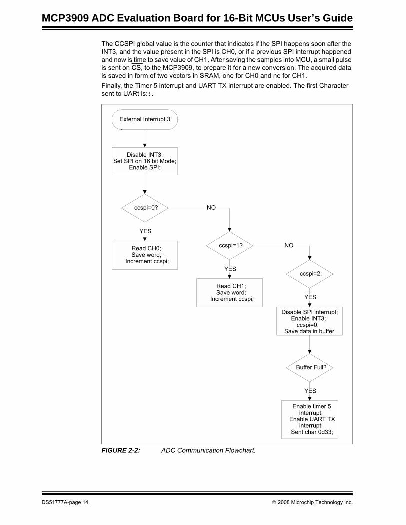
The CCSPI global value is the counter that indicates if the SPI happens soon after the INT3, and the value present in the SPI is CH0, or if a previous SPI interrupt happened and now is time to save value of CH1. After saving the samples into MCU, a small pulse is sent on CS, to the MCP3909, to prepare it for a new conversion. The acquired data is saved in form of two vectors in SRAM, one for CH0 and ne for CH1.Finally, the Timer 5 interrupt and UART TX interrupt are enabled. The first Character sent to UARt is:!.
FIGURE 2-2: ADC Communication Flowchart.
External Interrupt 3
Disable INT3;Set SPI on 16 bit Mode;
Enable SPI;
ccspi=0?
Read CH0;Save word;
Increment ccspi;
YES
ccspi=1?
NO
Read CH1;Save word;
Increment ccspi;
YESccspi=2;
NO
Disable SPI interrupt;Enable INT3;
ccspi=0;Save data in buffer
YES
Buffer Full?
Enable timer 5 interrupt;
Enable UART TX interrupt;
Sent char 0d33;
YES
Firmware
© 2008 Microchip Technology Inc. DS51777A-page 15
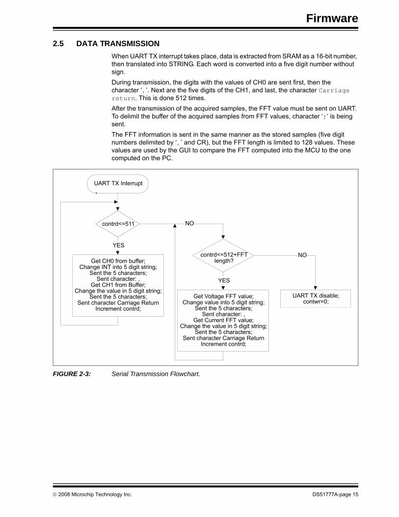
2.5 DATA TRANSMISSIONWhen UART TX interrupt takes place, data is extracted from SRAM as a 16-bit number, then translated into STRING. Each word is converted into a five digit number without sign.During transmission, the digits with the values of CH0 are sent first, then the character ‘,’. Next are the five digits of the CH1, and last, the character Carriage return. This is done 512 times.After the transmission of the acquired samples, the FFT value must be sent on UART. To delimit the buffer of the acquired samples from FFT values, character ‘;’ is being sent.The FFT information is sent in the same manner as the stored samples (five digit numbers delimited by ‘,’ and CR), but the FFT length is limited to 128 values. These values are used by the GUI to compare the FFT computed into the MCU to the one computed on the PC.
FIGURE 2-3: Serial Transmission Flowchart.
UART TX Interrupt
contrd<=511
Get CH0 from buffer;Change INT into 5 digit string;
Sent the 5 characters;Sent character: ,
Get CH1 from Buffer;Change the value in 5 digit string;
Sent the 5 characters;Sent character Carriage Return
Increment contrd;
YEScontrd<=512+FFT
length?
NO
YES
UART TX disable;contwr=0;
Get Voltage FFT value;Change value into 5 digit string;
Sent the 5 characters;Sent character: ,
Get Current FFT value;Change the value in 5 digit string;
Sent the 5 characters;Sent character Carriage Return
Increment contrd;
NO
MCP3909 ADC Evaluation Board for 16-Bit MCUs User’s Guide
DS51777A-page 16 © 2008 Microchip Technology Inc.
NOTES:
MCP3909 ADC EVALUATION BOARDFOR 16-BIT MCUs USER’S GUIDE
© 2008 Microchip Technology Inc. DS51777A-page 17
Chapter 3. MCP3909 PC Software Tool
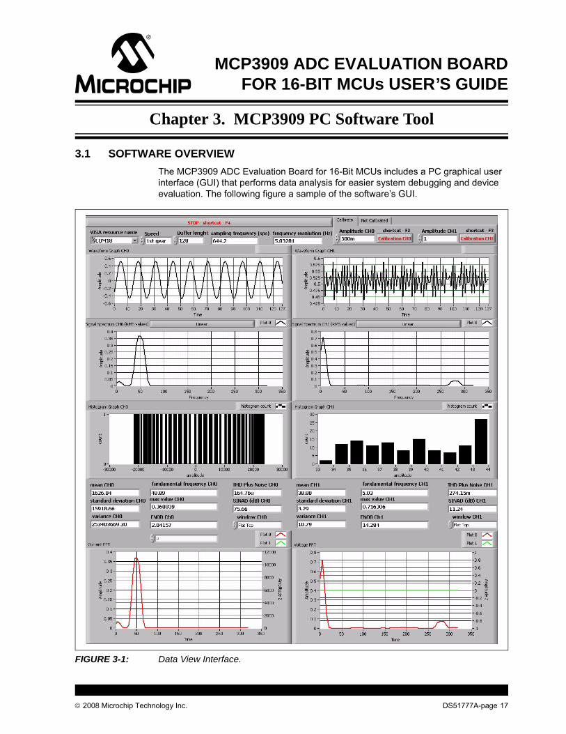
3.1 SOFTWARE OVERVIEWThe MCP3909 ADC Evaluation Board for 16-Bit MCUs includes a PC graphical user interface (GUI) that performs data analysis for easier system debugging and device evaluation. The following figure a sample of the software’s GUI.
FIGURE 3-1: Data View Interface.
MCP3909 ADC Evaluation Board for 16-Bit MCUs User’s Guide
DS51777A-page 18 © 2008 Microchip Technology Inc.
3.2 SETTING THE SAMPLE RATEOn the MCP3909 ADC Evaluation Board for 16-Bit MCUs is possible to select from five different sampling rates, referred here as gears. The control is placed in the up left areas of the GUI.The value of the sampling rate for each gear is as follows:• 1st gear - 644.2 sps• 2nd gear - 2963 sps• 3th gear - 4938 sps• 4th gear - 8888 sps• 5th gear - 14813 spsOnce the gear is changed, the actualized value of the sampling rate is indicated on the “Sampling Frequency (sps)” field. The “Frequency Resolution” field will indicate the space between spectral lines of the sampled signal, at the indicated sample rate.Changing the sampling rate in the GUI will not automatically change the one on the MCP3909 ADC Evaluation Board for 16-Bit MCUs. For this to happen it is necessary to manually change the gear, by pressing the RB9 button placed on the board.
3.3 CONNECTIVITY, RECORDING LENGTH AND CALIBRATION OF DATAThe PC is connected to the MCP3909 ADC Evaluation Board for 16-Bit MCUs through the RS232 cable. It is important to have a COM port on the PC. It is possible to use a USB to RS232 adaptor cable, for this case being necessary to write the number of the virtual COM port. To do this, right-click on My computer > Manage > Device Manager > Port (COM and LPT), and read the number in the parenthesis, after the device name.The COM port number must be selected in the “VISA Resource Name” field.The MCU is sending a big packet of data to the PC. If the user need to see only to a small part of the buffer, he will write the desired buffer length in the “Buffer length” field. The maximum length is 512 samples.The user have the option to choose between Calibrate and Not Calibrate tab from the up-right corner of the window. The calibration is possible for an AC signal measurement, calibrating the scale and selecting the desired unit of measure for the processed data.When selecting the Calibrate tab, two fields are shown: the “Amplitude CH0” and the “Amplitude CH1”, with the corresponding Calibration buttons. The user must write the peak-to-peak value in the two fields, and then press the Calibration button for each, or use the shortcuts (<F2> for CH0 and <F3> for CH1). If the Calibration button is not pressed, or the shortcut is not applied, plot screens will be empty.If the Not Calibrated tab is selected, the “Amplitude” fields and Calibration buttons are not visible, and the data plotted on the screen will be indicated in LSBs (in ADC code).To stop the GUI it is necessary to press the STOP button, or the <F4> shortcut key.
3.4 SCOPE PLOT WINDOW - TIME DOMAIN ANALYSISThe recorded samples from a buffer are indicated on the “Waveform Graphs” screens.The size of the X scale is given by the number showed in the “Buffer Length” field.If the Not Calibrated tab is selected, the value on Y axis will be given by the LSBs. If the data is calibrated, and calibration value is 0.5, for example, the data on the waveform graphs will have an amplitude peak-to-peak of 2x0.5. It is important to note that the offset is not removed.

MCP3909 PC Software Tool
© 2008 Microchip Technology Inc. DS51777A-page 19
3.5 HISTOGRAM WINDOW - NOISE ANALYSISFor the evaluation of the Effective Number Of Bits (ENOB) the GUI will compute some statistical parameters: “mean” value, “standard deviation” and “variance”, for each channel. These parameters can be seen at the bottom of the GUI, right under the Histogram Graph screens. The formula used for the ENOB is:
EQUATION 3-1:
The right value for the acquired ENOB is correct only when the DC signal is applied on the inputs.The distribution of noise from the acquired signal can be seen on the Histogram Graph screens.These graphs are indicating how many transitions took place in between two codes. In the case of a noiseless signal (a straight line), the histogram graphs will show nothing. If the signal is a digital noise signal (transition between two values) the histogram will indicate just one vertical bar.
3.6 FFT WINDOW - FREQUENCY DOMAIN ANALYSISThe spectrum of the acquired signal is visible in the Signal Spectrum screen. Above these graphics there is a button that can be used to set the Y scale to be linear or logarithmic. A logarithmic scale on Y axis is useful to see the level of low harmonics, or the noise floor.The length of the FFT is given by the buffer length and the sampling speed. The X axis is directly scaled in Hz units. Do remember when changing the sampling speed in the GUI, to manually change the sampling speed on the MCP3909 ADC Evaluation Board for 16-Bit MCUs.Another feature of the software is the window selection for the FFT computation. This is done from the “Window” fields, in the lower region of the GUI, right above the Current FFT screens. The user can select from a large number of windows.Since GUI is performing the spectral analysis of the acquired signal, it is possible to compute AC performance parameters of the ADC: “THD” and “SINAD” are shown on the indicators, right under the Histogram Graph screens.
3.7 AUXILIARY DATA WINDOWAt the bottom of the GUI there are two screens called Current FFT and Voltage FFT. These graphics are used to compare the FFT computed on the MCU (the green FFT) with the one computed on the PC (the red FFT). The Current channel is CH0, and the Voltage channel is CH1.In the beginning these graphs do not indicate anything. For a correct use it is necessary to have the same window used on both MCU and PC. In addition, on the PC, the Linear scale for the FFT must be used.Because on the MCU the FFT has 128 points in length, the buffer length should be the same.The MCU is not sending the data to the PC simultaneously. To choose which view to see (Current FFT or Voltage FFT), press SW3 placed on the board.
ENOB 16 log2 σ( )–=

MCP3909 ADC Evaluation Board for 16-Bit MCUs User’s Guide
DS51777A-page 20 © 2008 Microchip Technology Inc.
NOTES:
MCP3909 ADC EVALUATION BOARDFOR 16-BIT MCUs USER’S GUIDE
© 2008 Microchip Technology Inc. DS51777A-page 21
Appendix A. Schematics and Layouts
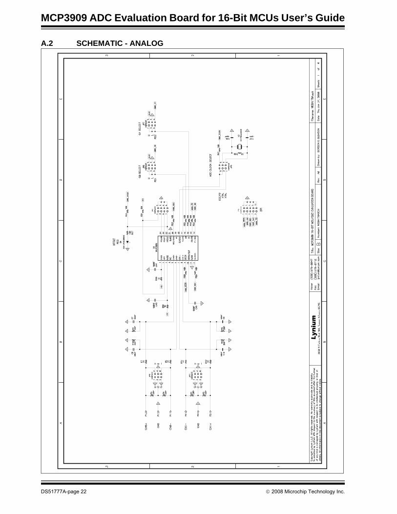
A.1 INTRODUCTIONThis appendix contains the following schematics of the MCP3909 ADC Evaluation Board for 16-Bit MCUs.
• Schematic - Analog• Schematic - LCD and UART• Schematic - USB and Memory• Schematic - Microcontroller (MCU)• Schematic - PIM Module• Schematic - Power• Board - Top Trace and Top Silk• Board - Bottom Trace and Bottom Silk• Board - Layer #2 VDD• Board - Layer #3 GND• Board - Top Silk and Pads• Board - Bottom Silk and Pads
MCP3909 ADC Evaluation Board for 16-Bit MCUs User’s Guide
DS51777A-page 22 © 2008 Microchip Technology Inc.
A.2 SCHEMATIC - ANALOG
Lynium
Schematics and Layouts
© 2008 Microchip Technology Inc. DS51777A-page 23
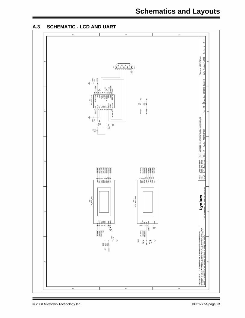
A.3 SCHEMATIC - LCD AND UART
Lynium
MCP3909 ADC Evaluation Board for 16-Bit MCUs User’s Guide
DS51777A-page 24 © 2008 Microchip Technology Inc.
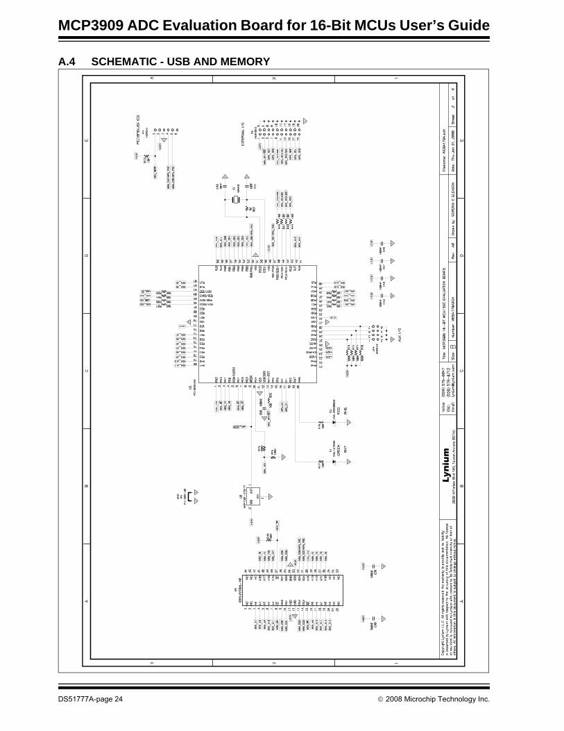
A.4 SCHEMATIC - USB AND MEMORY
Lynium
Schematics and Layouts
© 2008 Microchip Technology Inc. DS51777A-page 25
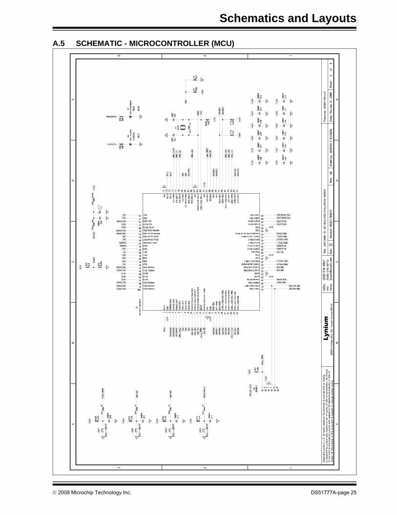
A.5 SCHEMATIC - MICROCONTROLLER (MCU)
Lynium
MCP3909 ADC Evaluation Board for 16-Bit MCUs User’s Guide
DS51777A-page 26 © 2008 Microchip Technology Inc.
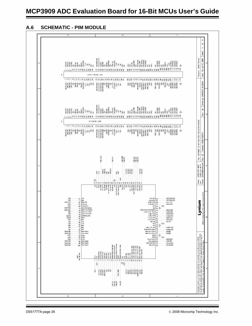
A.6 SCHEMATIC - PIM MODULE
Lynium
Schematics and Layouts
© 2008 Microchip Technology Inc. DS51777A-page 27
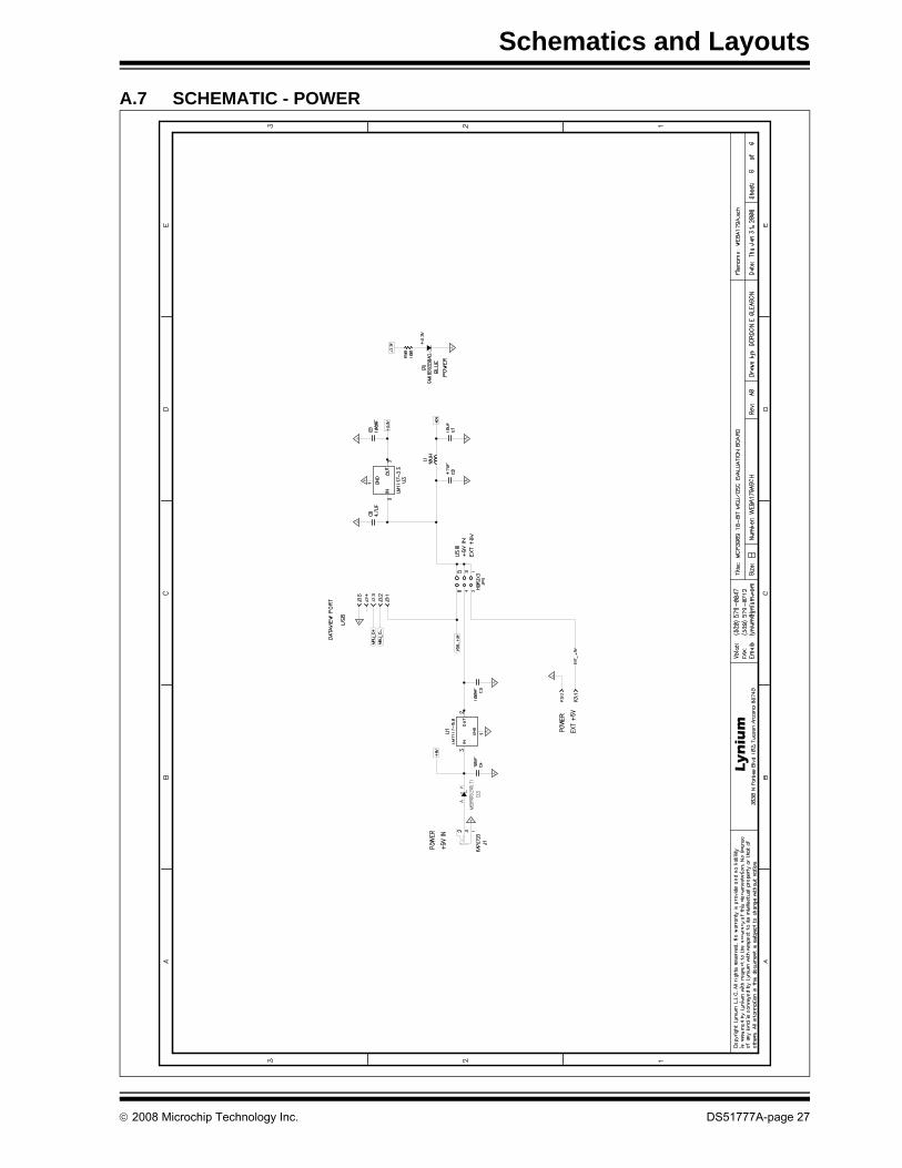
A.7 SCHEMATIC - POWER
Lynium
MCP3909 ADC Evaluation Board for 16-Bit MCUs User’s Guide
DS51777A-page 28 © 2008 Microchip Technology Inc.
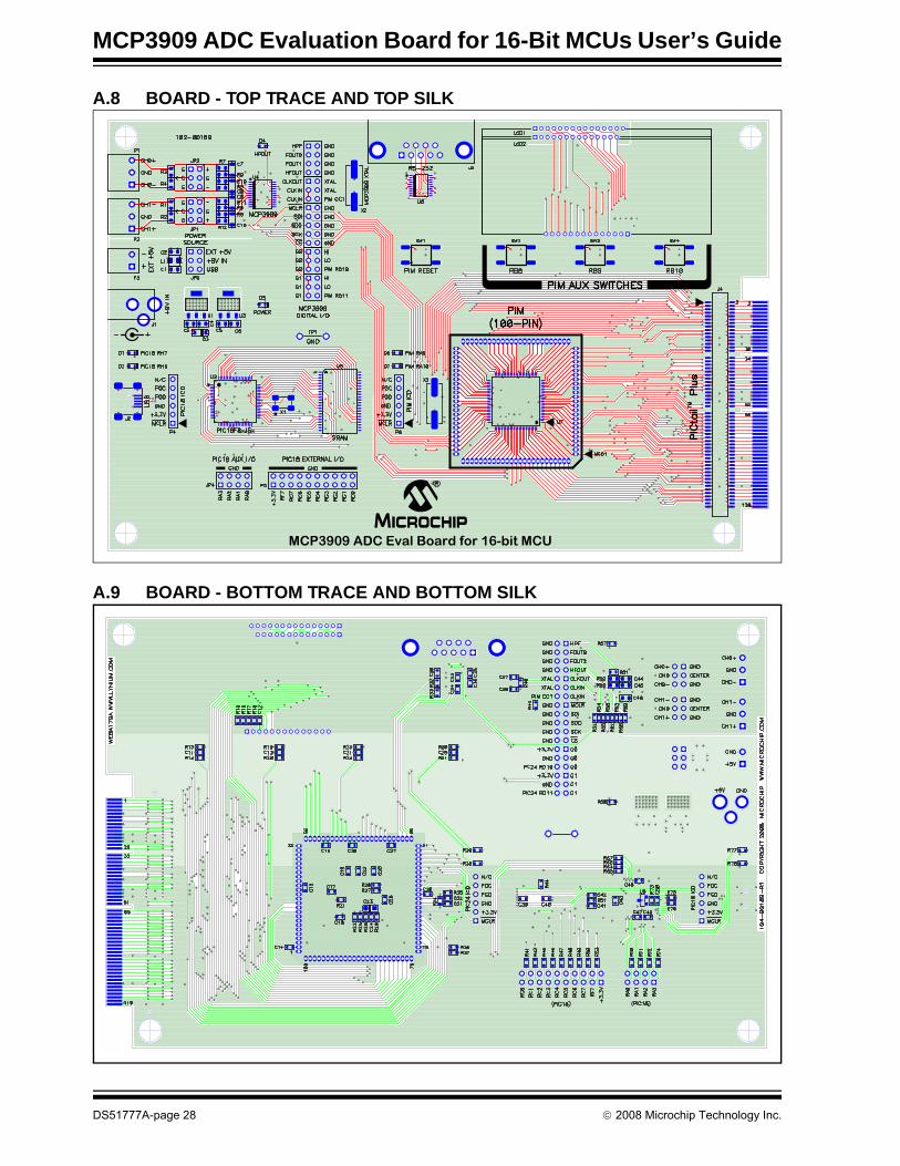
A.8 BOARD - TOP TRACE AND TOP SILK
A.9 BOARD - BOTTOM TRACE AND BOTTOM SILK
MCP3909 ADC Eval Board for 16-bit MCU
Schematics and Layouts
© 2008 Microchip Technology Inc. DS51777A-page 29
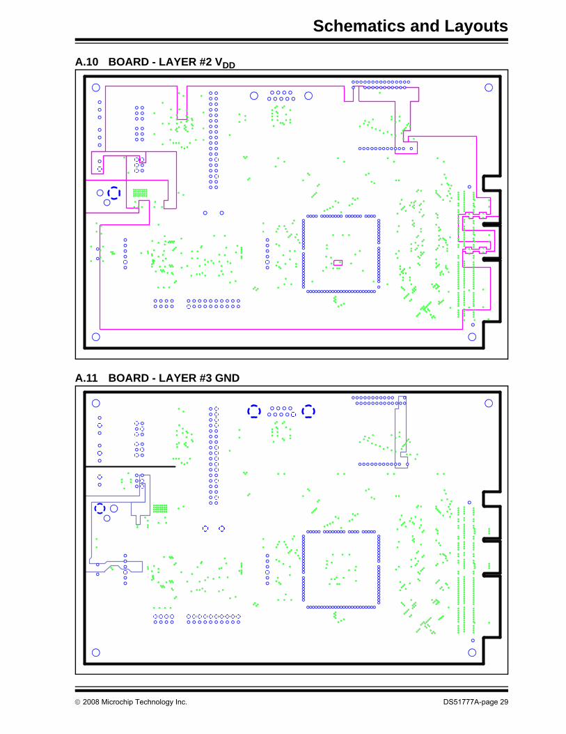
A.10 BOARD - LAYER #2 VDD
A.11 BOARD - LAYER #3 GND
MCP3909 ADC Evaluation Board for 16-Bit MCUs User’s Guide
DS51777A-page 30 © 2008 Microchip Technology Inc.
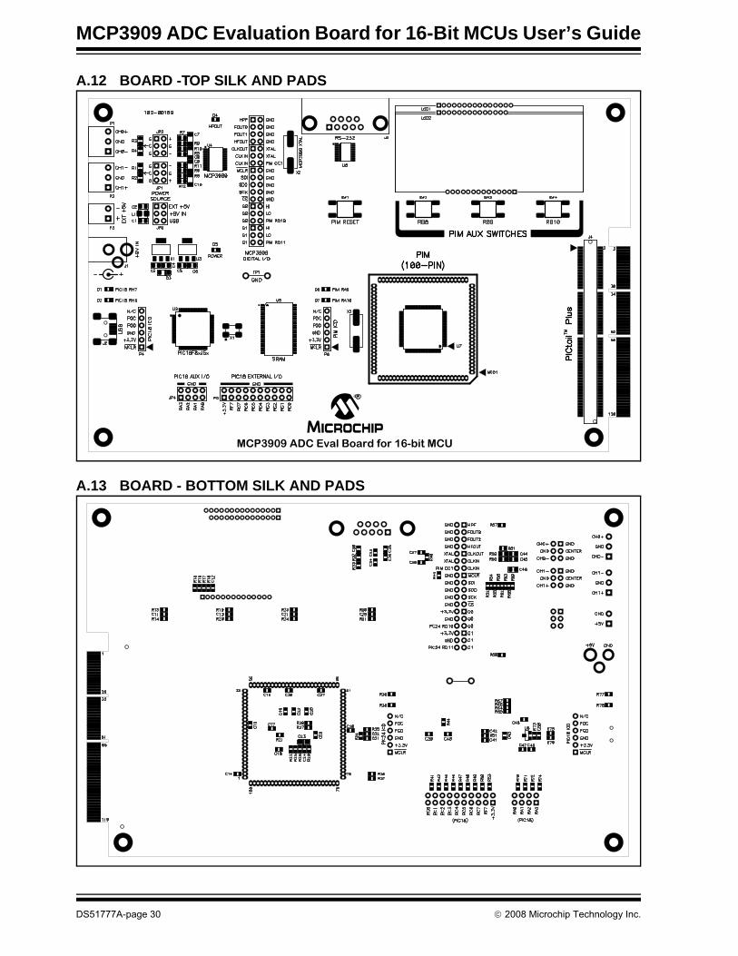
A.12 BOARD -TOP SILK AND PADS
A.13 BOARD - BOTTOM SILK AND PADS
MCP3909 ADC Eval Board for 16-bit MCU
MCP3909 ADC EVALUATION BOARDFOR 16-BIT MCUs USER’S GUIDE
© 2008 Microchip Technology Inc. DS51777A-page 31
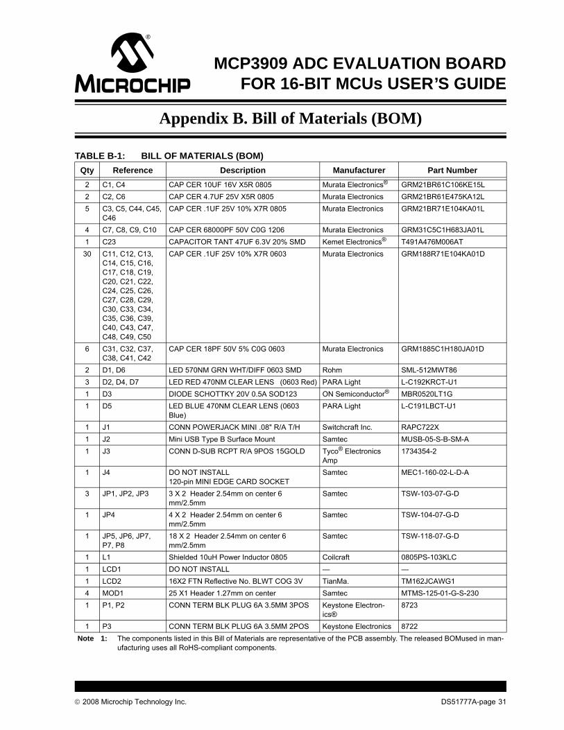
Appendix B. Bill of Materials (BOM)
TABLE B-1: BILL OF MATERIALS (BOM)Qty Reference Description Manufacturer Part Number
2 C1, C4 CAP CER 10UF 16V X5R 0805 Murata Electronics® GRM21BR61C106KE15L2 C2, C6 CAP CER 4.7UF 25V X5R 0805 Murata Electronics GRM21BR61E475KA12L5 C3, C5, C44, C45,
C46CAP CER .1UF 25V 10% X7R 0805 Murata Electronics GRM21BR71E104KA01L
4 C7, C8, C9, C10 CAP CER 68000PF 50V C0G 1206 Murata Electronics GRM31C5C1H683JA01L1 C23 CAPACITOR TANT 47UF 6.3V 20% SMD Kemet Electronics® T491A476M006AT
30 C11, C12, C13, C14, C15, C16, C17, C18, C19, C20, C21, C22, C24, C25, C26, C27, C28, C29, C30, C33, C34, C35, C36, C39, C40, C43, C47, C48, C49, C50
CAP CER .1UF 25V 10% X7R 0603 Murata Electronics GRM188R71E104KA01D
6 C31, C32, C37, C38, C41, C42
CAP CER 18PF 50V 5% C0G 0603 Murata Electronics GRM1885C1H180JA01D
2 D1, D6 LED 570NM GRN WHT/DIFF 0603 SMD Rohm SML-512MWT863 D2, D4, D7 LED RED 470NM CLEAR LENS (0603 Red) PARA Light L-C192KRCT-U11 D3 DIODE SCHOTTKY 20V 0.5A SOD123 ON Semiconductor® MBR0520LT1G1 D5 LED BLUE 470NM CLEAR LENS (0603
Blue)PARA Light L-C191LBCT-U1
1 J1 CONN POWERJACK MINI .08" R/A T/H Switchcraft Inc. RAPC722X1 J2 Mini USB Type B Surface Mount Samtec MUSB-05-S-B-SM-A1 J3 CONN D-SUB RCPT R/A 9POS 15GOLD Tyco® Electronics
Amp1734354-2
1 J4 DO NOT INSTALL120-pin MINI EDGE CARD SOCKET
Samtec MEC1-160-02-L-D-A
3 JP1, JP2, JP3 3 X 2 Header 2.54mm on center 6 mm/2.5mm
Samtec TSW-103-07-G-D
1 JP4 4 X 2 Header 2.54mm on center 6 mm/2.5mm
Samtec TSW-104-07-G-D
1 JP5, JP6, JP7, P7, P8
18 X 2 Header 2.54mm on center 6 mm/2.5mm
Samtec TSW-118-07-G-D
1 L1 Shielded 10uH Power Inductor 0805 Coilcraft 0805PS-103KLC1 LCD1 DO NOT INSTALL — —1 LCD2 16X2 FTN Reflective No. BLWT COG 3V TianMa. TM162JCAWG14 MOD1 25 X1 Header 1.27mm on center Samtec MTMS-125-01-G-S-2301 P1, P2 CONN TERM BLK PLUG 6A 3.5MM 3POS Keystone Electron-
ics®8723
1 P3 CONN TERM BLK PLUG 6A 3.5MM 2POS Keystone Electronics 8722Note 1: The components listed in this Bill of Materials are representative of the PCB assembly. The released BOMused in man-
ufacturing uses all RoHS-compliant components.

Bill of Materials (BOM)
© 2008 Microchip Technology Inc. DS51777A-page 32
1 P3 TERM BLK PIN HEADER 24Pin PosOne 24 Pin Header is enough for 3 Boards
Keystone Electronics 8724
1 P5 10 X2 Header 2.54mm on center 6 mm/2.5mm
Samtec TSW-110-07-G-D
1 P9 DO NOT INSTALL — —1 PCB RoHS Compliant Bare PCB, MCP3909 ADC
Evaluation Board for 16-Bit MCUsMicrochip Technology Inc.
104-000189
13 R1, R2, R3, R4, R6, R8, R9, R10, R17, R18, R25, R29, R35
DO NOT INSTALL — —
4 R5, R7, R11, R12 RES 1.0K OHM .1% 1/4W 0805 SMD Susumu Co Ltd RGH2012-2E-P-102-B4 R13, R19, R23,
R30RES 4.70K OHM 1/10W 1% 0603 SMD Rohm MCR03EZPFX4701
8 R14, R20, R24, R31, R32, R33, R36, R37
RES 1.00K OHM 1/10W 1% 0603 SMD Rohm MCR03EZPFX1001
4 R15, R21, R61, R73
RES 10.0K OHM 1/10W 1% 0603 SMD Rohm MCR03EZPFX1002
1 R16 RES 1.30K OHM 1/10W 1% 0603 SMD Rohm MCR03EZPFX13012 R22, R26 RES 0.0 OHM 1/10W 5% 0603 SMD Rohm MCR03EZPJ0002 R27, R28 RES 2.20K OHM 1/10W 1% 0603 SMD Rohm MCR03EZPFX22013 R34, R40, R51 RES 1.00M OHM 1/10W 1% 0603 SMD Rohm MCR03EZPFX1004
28 R38, R39, R41, R42, R43, R45, R46, R47, R48, R49, R50, R52, R53, R54, R55, R56, R57, R58, R62, R63, R64, R65, R66, R67, R68, R69, R77, R78
RES 100 OHM 1/10W 1% 0603 SMD Rohm MCR03EZPFX1000
7 R44, R70, R71, R72, R74, R75, R76
RES 100K OHM 1/10W 1% 0603 SMD Rohm MCR03EZPFX1003
2 R59, R60 RES 10.0 OHM 1/8W 1% 0805 SMD Rohm MCR10EZHF10R04 SW1,SW2, SW3,
SW4SWITCH TACT 6MM 230GF H=4.3MM Omron Electronics Inc
- ECB DivB3S-1002P
1 TP1 Wire Test Point 0.3" Length Component Corporation
PJ-202-30
1 U1 IC REG LDO 800MA 5.0V SOT-223 National Semiconductor
LM1117MP-5.0/NOPB
1 U2 IC PIC USB MCU FLASH 48KX16 80TQFP Microchip TechnologyInc
PIC18F86J55-I/PT
1 U3 IC REG LDO 800MA 3.3V SOT-223 National Semiconductor
LM1117MP-3.3/NOPB
1 U4 IC ENERGY METER 24SSOP Microchip TechnologyInc
MCP3909-I/SS
1 U5 IC SRAM 4MB ASYNC 44-TSOPII ISSI, Integrated Silicon Solution Inc
IS61LV5128AL-10TLI
1 U6 IC DRVR/RCVR MLTCH RS232 20TSSOP Texas Instruments MAX3223IPWR1 U7 DO NOT INSTALL — —
TABLE B-1: BILL OF MATERIALS (BOM) (CONTINUED)Qty Reference Description Manufacturer Part Number
Note 1: The components listed in this Bill of Materials are representative of the PCB assembly. The released BOMused in man-ufacturing uses all RoHS-compliant components.
Bill of Materials (BOM)
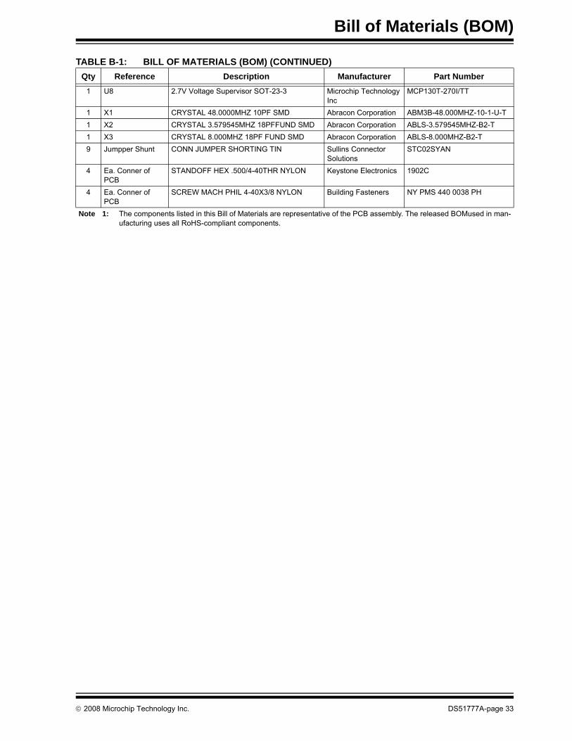
© 2008 Microchip Technology Inc. DS51777A-page 33
1 U8 2.7V Voltage Supervisor SOT-23-3 Microchip TechnologyInc
MCP130T-270I/TT
1 X1 CRYSTAL 48.0000MHZ 10PF SMD Abracon Corporation ABM3B-48.000MHZ-10-1-U-T1 X2 CRYSTAL 3.579545MHZ 18PFFUND SMD Abracon Corporation ABLS-3.579545MHZ-B2-T1 X3 CRYSTAL 8.000MHZ 18PF FUND SMD Abracon Corporation ABLS-8.000MHZ-B2-T9 Jumpper Shunt CONN JUMPER SHORTING TIN Sullins Connector
SolutionsSTC02SYAN
4 Ea. Conner of PCB
STANDOFF HEX .500/4-40THR NYLON Keystone Electronics 1902C
4 Ea. Conner of PCB
SCREW MACH PHIL 4-40X3/8 NYLON Building Fasteners NY PMS 440 0038 PH
TABLE B-1: BILL OF MATERIALS (BOM) (CONTINUED)Qty Reference Description Manufacturer Part Number
Note 1: The components listed in this Bill of Materials are representative of the PCB assembly. The released BOMused in man-ufacturing uses all RoHS-compliant components.
DS51777A-page 34 © 2008 Microchip Technology Inc.
AMERICASCorporate Office2355 West Chandler Blvd.Chandler, AZ 85224-6199Tel: 480-792-7200 Fax: 480-792-7277Technical Support: http://support.microchip.comWeb Address: www.microchip.comAtlantaDuluth, GA Tel: 678-957-9614 Fax: 678-957-1455BostonWestborough, MA Tel: 774-760-0087 Fax: 774-760-0088ChicagoItasca, IL Tel: 630-285-0071 Fax: 630-285-0075DallasAddison, TX Tel: 972-818-7423 Fax: 972-818-2924DetroitFarmington Hills, MI Tel: 248-538-2250Fax: 248-538-2260KokomoKokomo, IN Tel: 765-864-8360Fax: 765-864-8387Los AngelesMission Viejo, CA Tel: 949-462-9523 Fax: 949-462-9608Santa ClaraSanta Clara, CA Tel: 408-961-6444Fax: 408-961-6445TorontoMississauga, Ontario, CanadaTel: 905-673-0699 Fax: 905-673-6509
ASIA/PACIFICAsia Pacific OfficeSuites 3707-14, 37th FloorTower 6, The GatewayHarbour City, KowloonHong KongTel: 852-2401-1200Fax: 852-2401-3431Australia - SydneyTel: 61-2-9868-6733Fax: 61-2-9868-6755China - BeijingTel: 86-10-8528-2100 Fax: 86-10-8528-2104China - ChengduTel: 86-28-8665-5511Fax: 86-28-8665-7889China - Hong Kong SARTel: 852-2401-1200 Fax: 852-2401-3431China - NanjingTel: 86-25-8473-2460Fax: 86-25-8473-2470China - QingdaoTel: 86-532-8502-7355Fax: 86-532-8502-7205China - ShanghaiTel: 86-21-5407-5533 Fax: 86-21-5407-5066China - ShenyangTel: 86-24-2334-2829Fax: 86-24-2334-2393China - ShenzhenTel: 86-755-8203-2660 Fax: 86-755-8203-1760China - WuhanTel: 86-27-5980-5300Fax: 86-27-5980-5118China - XiamenTel: 86-592-2388138 Fax: 86-592-2388130China - XianTel: 86-29-8833-7252Fax: 86-29-8833-7256China - ZhuhaiTel: 86-756-3210040 Fax: 86-756-3210049
ASIA/PACIFICIndia - BangaloreTel: 91-80-4182-8400 Fax: 91-80-4182-8422India - New DelhiTel: 91-11-4160-8631Fax: 91-11-4160-8632India - PuneTel: 91-20-2566-1512Fax: 91-20-2566-1513Japan - YokohamaTel: 81-45-471- 6166 Fax: 81-45-471-6122Korea - DaeguTel: 82-53-744-4301Fax: 82-53-744-4302Korea - SeoulTel: 82-2-554-7200Fax: 82-2-558-5932 or 82-2-558-5934Malaysia - Kuala LumpurTel: 60-3-6201-9857Fax: 60-3-6201-9859Malaysia - PenangTel: 60-4-227-8870Fax: 60-4-227-4068Philippines - ManilaTel: 63-2-634-9065Fax: 63-2-634-9069SingaporeTel: 65-6334-8870Fax: 65-6334-8850Taiwan - Hsin ChuTel: 886-3-572-9526Fax: 886-3-572-6459Taiwan - KaohsiungTel: 886-7-536-4818Fax: 886-7-536-4803Taiwan - TaipeiTel: 886-2-2500-6610 Fax: 886-2-2508-0102Thailand - BangkokTel: 66-2-694-1351Fax: 66-2-694-1350
EUROPEAustria - WelsTel: 43-7242-2244-39Fax: 43-7242-2244-393Denmark - CopenhagenTel: 45-4450-2828 Fax: 45-4485-2829France - ParisTel: 33-1-69-53-63-20 Fax: 33-1-69-30-90-79Germany - MunichTel: 49-89-627-144-0 Fax: 49-89-627-144-44Italy - Milan Tel: 39-0331-742611 Fax: 39-0331-466781Netherlands - DrunenTel: 31-416-690399 Fax: 31-416-690340Spain - MadridTel: 34-91-708-08-90Fax: 34-91-708-08-91UK - WokinghamTel: 44-118-921-5869Fax: 44-118-921-5820
WORLDWIDE SALES AND SERVICE
01/02/08