Embed Size (px)
Citation preview
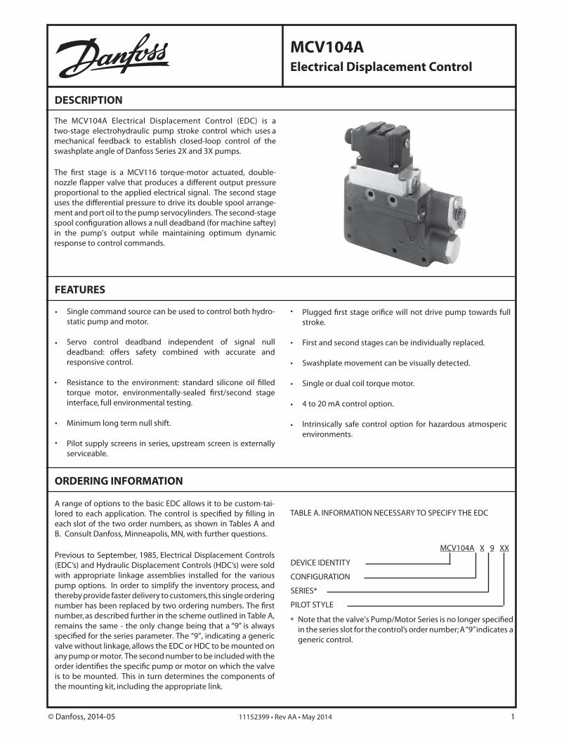
MCV104AElectrical Displacement Control
DESCRIPTION
ORDERING INFORMATION
TABLE A. INFORMATION NECESSARY TO SPECIFY THE EDC
DEVICE IDENTITY
CONFIGURATION
SERIES*
PILOT STYLE
MCV104A X 9 XX
FEATURES
•
•
•
•
•
•
•
•
•
© Danfoss, 2014-05 11152399 • Rev AA • May 2014 1
The MCV104A Electrical Displacement Control (EDC) is a two-stage electrohydraulic pump stroke control which uses a mechanical feedback to establish closed-loop control of the swashplate angle of Danfoss Series 2X and 3X pumps.
The first stage is a MCV116 torque-motor actuated, double- nozzle flapper valve that produces a different output pressure proportional to the applied electrical signal. The second stage uses the differential pressure to drive its double spool arrange-ment and port oil to the pump servocylinders. The second-stage spool configuration allows a null deadband (for machine saftey) in the pump’s output while maintaining optimum dynamic response to control commands.
Single command source can be used to control both hydro-static pump and motor.
Servo control deadband independent of signal null deadband: offers safety combined with accurate and responsive control.
Resistance to the environment: standard silicone oil filled torque motor, environmentally-sealed first/second stage interface, full environmental testing.
Minimum long term null shift.
Pilot supply screens in series, upstream screen is externally serviceable.
Plugged first stage orifice will not drive pump towards full stroke.
First and second stages can be individually replaced.
Swashplate movement can be visually detected.
Single or dual coil torque motor.
4 to 20 mA control option.
Intrinsically safe control option for hazardous atmosperic environments.
•
A range of options to the basic EDC allows it to be custom-tai-lored to each application. The control is specified by filling in each slot of the two order numbers, as shown in Tables A and B. Consult Danfoss, Minneapolis, MN, with further questions.
Previous to September, 1985, Electrical Displacement Controls (EDC’s) and Hydraulic Displacement Controls (HDC’s) were sold with appropriate linkage assemblies installed for the various pump options. In order to simplify the inventory process, and thereby provide faster delivery to customers, this single ordering number has been replaced by two ordering numbers. The first number, as described further in the scheme outlined in Table A, remains the same - the only change being that a “9” is always specified for the series parameter. The “9”, indicating a generic valve without linkage, allows the EDC or HDC to be mounted on any pump or motor. The second number to be included with the order identifies the specific pump or motor on which the valve is to be mounted. This in turn determines the components of the mounting kit, including the appropriate link.
Note that the valve’s Pump/Motor Series is no longer specified in the series slot for the control’s order number; A “9” indicates a generic control.
*
ORDERING INFORMATION (continued)
DEVICE IDENTITY This is the basic EDC. The model code is MCV104A.
CONFIGURATION
MODELCODE
PRESSUREOVERRIDE
HIGHRESPONSE
SERVOPORTS
12345678
YesYesNo
YesYes
Yes
YesNoYes
Yes
YesYesYesYesNo
TABLE B. INFORMATION NECESSARY TO SPECIFY THE KIT AS-SEMBLY.
SERIES
DESCRIPTION
9 Any Pump, Less Linkage
MODEL
The model code is “9”.
PILOT STYLE
MODEL DESCRIPTION
22
23
26
27
40
04
PRODUCT TYPE
KIT TYPE
PUMP SERIES
KK XXX
SPARE PARTS
PRODUCT TYPE The model code is "04".
PUMP SERIES 20 - 27, 33, 34, or 36.
KIT TYPE
MODEL CODE DESCRIPTION
1 Standard EDC
2 EDC with POR
* Pressure Override Only
© Danfoss, 2014-05 11152399 • Rev AA • May 2014 2
The pressure override and pressure limiter accomplish the same function - they shift the pump swashplate toward neutral when system pressure exceeds a preset threshold. They thus limit maximum system pressure, protect components from heat generated by flow across relief valves and conserve pump horsepower. Pressure override is available only for Series 2X pumps, and pressure limiting is available only for 3X pumps. Pressure limiting and annular control are not available togeth-er. If the model code chosen indicates that pressure override function is desired (i.e.,”yes” is chosen in the second column of the configuration parameter, above). The pressure override valve must be obtained through Danfoss, Ames, IA. The pressure limiting feature is inherent in the design of the MCV104 when applied with the 3X pump.
High response configuration increases swashplate response.
Silicone oil filled, single coil, Parkard connector
Silicone oil filled, dual coil, Parkard connector
Silicone oil filled, single coil, MS connector
Silicone oil filled, single coil, Parkard connector (4-20 mA)
Silicone oil filled, dual coil, MS connector
It may be preferred to apply the dual coil versus the single coil EDC. The dual coil allows two command sources to be combined at the torque motor, the resulting signal being the difference between the two. Dual coil models can be connected in parallel or series offering the flexibility when electric requirements change.
The torque motor cavity is oil-filled, which prevents moisture from condensing on the inside during extreme temperature changes. Dual coil valves have all four pin connections active. See the Wiring section.
Valve mounting hardware in the kit includes: orifices, retaining ring, drag link, spacer plate, swashplate pin, link and ball assem-bly, hex screws, O-rings and gaskets. In some cases not all the above are necessary for installation and they are not included in the kit.
Several Danfoss variable pumps come without premounted controls. These pumps will need additional mounting hardware that generally accompanies the control in order to accomo-date the EDC. The pump numbers are: 34-2035, 34-2060, 34-2080, 36-2047, 36-2056, 36-2081, 36-2082.
If you wish to mount an EDC on one of these pumps, order a K07015 (9004700-1212) roll pin, a 9004875-0020 straight pin and a 9340301 (for Series 34 pumps) or 9360354 (for Series 36 pumps) drag link.
See the Spare Parts Section of this book for a list of spare parts available for the MCV104. Other non-standard spare parts, such as orifices. may be available upon request.
Order Danfoss Pressure Override Valve through Order Danfoss Pressure Override Valve through Danfoss, Ames, IA (515) 239-6000 or Danfoss Distributors.
Order the EDC either factory installed on pumps or as an individual control.
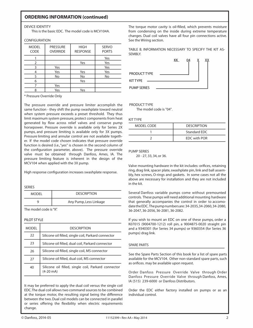
SPARE PARTS
1238F
36 - 42
30 - 32
1 - 2 3 - 4 5 296
7
89
10
11
12
13
14
3325
2615 - 16
17 - 2234 - 35
23 - 24
27 - 28
For items 17, 18, 20, 21, 22, 25 and 36-42 it is recommended to purchase the appropriate installation kit ensuring the necessary items for a complete EDC installation.
Item 30 is used for the 14-85 mA models.Item 31 is used for the 4-20 mA models.
ITEM PART ITEM PART NUMBER NUMBER (QUANTITY) DESCRIPTION NUMBER NUMBER (QUANTITY) DESCRIPTION
1 K03383 (1) Mating Connector 2-Pin (Unassembled) 22 K07182 (1) EDC Gasket
2 K03384 (1) Mating Connector 4-Pin (Unassembled) 23 K07160 (1) Linkage Bushing
3 K03377 (1) Device Connector 2-Pin (Unassembled) 24 K07009 (1) O-Ring, (1) Linkage Bushing
4 K03378 (1) Device Connector 4-Pin (Unassembled) 25 K02611 (1) Snap Ring
5 K08106 (1) Bag Assembly (Mating Connector) 26 K04448 (1) Plug
6 K07055 (4) #10-24 X 5/8 Socket Head Cap Screw 27 K07159 (1) Plug
7 K01291 (2) Plug 28 K07010 (1) O-Ring for Item 27
8 K22582 (1) Filter Assmebly 29 CAUTION (4) Do Not Remove Cover Screws
9 K07034 (2) Screw, Neutral Adjust Cover 30 K02361 (1) Piston Pack 14-85 mA
10 K08387 (1) Seal Washer 31 K15631 (1) Piston Pack 4-20 mA
11 K10911 (1) Seal Washer Retainer 32 K07008 (1) O-Ring Piston Pack
12 K07000 (1) #3/8-32 Nut, Neutral Adjust Lock 33 K07005 (1) O-Ring Link Shaft
13 K08133 (1) Gasket Neutral Adjust Cover 34 K07151 (1) Spool Standard
14 K07158 (1) Neutral Adjust Cover 35 K07150 (1) Spool High Response
15 K07028 (1) Plug 36 K03272 (1) Link & Ball Assembly, 20 Frame
16 K07011 (1) O-Ring For Item 15 37 K03273 (1) Link & Ball Assembly, 21/22 Frame
17 K07163 (1) Spacer - SS 20 38 K03274 (1) Link & Ball Assembly, 23 Frame
18 K07164 (1) Spacer - SS 26 39 K03275 (1) Link & Ball Assembly, 24 Frame
19 K07128 (3) Port Screens 40 K03276 (1) Link & Ball Assembly, 25 Frame
21 K07006 (3) O-Ring For Ports 42 K03278 (1) Link & Ball Assembly, 27 Frame
© Danfoss, 2014-05 11152399 • Rev AA • May 2014 3
20 K07136 (2) .052 Orifice 41 K03277 (1) Link & Ball Assembly, 26 Frame
9
8765
4
3
21
1011
12
13
14
1515
16 1718
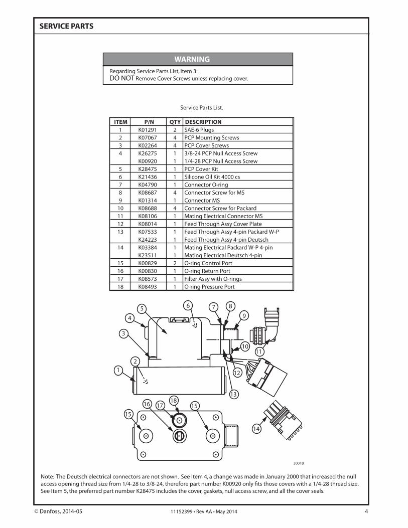
SERVICE PARTS
Service Parts List.
3001B
WARNING
Note: The Deutsch electrical connectors are not shown. See Item 4, a change was made in January 2000 that increased the null access opening thread size from 1/4-28 to 3/8-24, therefore part number K00920 only fits those covers with a 1/4-28 thread size.See Item 5, the preferred part number K28475 includes the cover, gaskets, null access screw, and all the cover seals.
Regarding Service Parts List, Item 3: DO NOT Remove Cover Screws unless replacing cover.
ITEM P/N QTY DESCRIPTION1 K01291 2 SAE-6 Plugs2 K07067 4 PCP Mounting Screws3 K02264 4 PCP Cover Screws4 K26275 1 3/8-24 PCP Null Access Screw
K00920 1 1/4-28 PCP Null Access Screw5 K28475 1 PCP Cover Kit6 K21436 1 Silicone Oil Kit 4000 cs7 K04790 1 Connector O-ring8 K08687 4 Connector Screw for MS9 K01314 1 Connector MS
10 K08688 4 Connector Screw for Packard11 K08106 1 Mating Electrical Connector MS12 K08014 1 Feed Through Assy Cover Plate13 K07533 1 Feed Through Assy 4-pin Packard W-P
K24223 1 Feed Through Assy 4-pin Deutsch14 K03384 1 Mating Electrical Packard W-P 4-pin
K23511 1 Mating Electrical Deutsch 4-pin15 K00829 2 O-ring Control Port16 K00830 1 O-ring Return Port17 K08573 1 Filter Assy with O-rings18 K08493 1 O-ring Pressure Port
© Danfoss, 2014-05 11152399 • Rev AA • May 2014 4
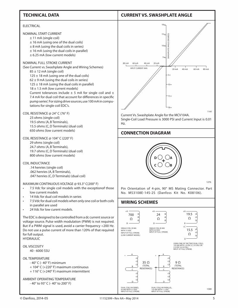
TECHNICAL DATA
ELECTRICAL
NOMINAL START CURRENT ± 11 mA (single coil) ± 16 mA (using one of the dual coils) ± 8 mA (using the dual coils in series) ± 16 mA (using the dual coils in parallel) ± 6.25 mA (low current models)
NOMINAL FULL STROKE CURRENT(See Current vs. Swashplate Angle and Wiring Schemes) 85 ± 12 mA (single coil) 125 ± 18 mA (using one of the dual coils) 62 ± 9 mA (using the dual coils in series) 125 ± 18 mA (using the dual coils in parallel) 18 ± 1.5 mA (low current models) Current tolerances include ± 5 mA for single coil and ±
7.4 mA for dual coil that account for differences in specific pump series’. For sizing drive sources, use 100 mA in compu-tations for single coil EDC’s.
COIL RESISTANCE @ 24° C (76° F) 23 ohms (single coil) 19.5 ohms (A, B Terminals), 15.5 ohms (C, D Terminals) (dual coil) 650 ohms (low current models)
COIL RESISTANCE @ 104° C (220° F) 29 ohms (single coil) 24.7 ohms (A, B Terminals), 19.7 ohms (C, D Terminals) (dual coil) 800 ohms (low current models)
COIL INDUCTANCE .14 henries (single coil) .062 henries (A, B Terminals), .047 henries (C, D Terminals) (dual coil)
MAXIMUM CONTINUOUS VOLTAGE @ 93.3° C(200° F)• 7.5 Vdc for single coil models with the exceptionof those
low current models• 14 Vdc for dual coil models in series• 7.5 Vdc for dual coil models when only one coil or both coils
in parallel are used• 24 Vdc for low curent models.
The EDC is designed to be controlled from a dc current source or voltage source. Pulse width modulation (PWM) is not required. But if a PWM signal is used, avoid a carrier frequency <200 Hz. Do not use a pulse current of more than 120% of that required for full output.HYDRAULIC
OIL VISCOSITY 40 - 6000 SSU
OIL TEMPERATURE - 40° C (- 40° F) minimum + 104° C (+220° F) maximum continuous + 116° C (+240° F) maximum intermittent
AMBIENT OPERATING TEMPERATURE - 40° to 93° C (- 40° to 200° F)
SINGLE COIL 85 MAWITH 2.0 VDCINPUT AT FULL STROKE.
+A
B
USING ONE OF THE TWO DUAL COILS,125 MA WITH 1.9 VDC (C, D COIL) OR2.4 VDC (A, B COIL)INPUT AT FULL STROKE.
+A
B
+C
D
DUAL COILS IN SERIES,62 MA WITH 2.2 VDCINPUT AT FULL STROKE.
+
B
C
D
A
DUAL COILS IN PARALLEL,125 MA WITH 1.1 VDCINPUT AT FULL STROKE.
+
B
C
D
A
+A
B
SINGLE COIL 20 MAWITH 15 VDCINPUT AT FULL STROKE.(LOW CURRENT MODEL)
CURRENT VS. SWASHPLATE ANGLE
Current Vs. Swashplate Angle for the MCV104A. Single-Coil Load Pressure is 3000 PSI and Current Input is 0.01 Hz.
1141
15∞
10∞
5∞
5∞
10∞
15∞
80 mA 60 mA 40 mA 20 mA
20 mA 40 mA 60 mA 80 mA
18∞
18∞
SWA
SHPL
ATE
AN
GLE
(DEG
REES
)
INPUT CURRENT (MA)
1300
WIRING SCHEMES
CONNECTION DIAGRAM
Pin Orientation of 4-pin, 90° MS Mating Connector. Part No. MS3108E-14S-2S (Danfoss Kit No. K08106).
1276
D
C
A
B
700Ω
24Ω
19.5Ω
15.5Ω
35 Ω(TOTAL
RESISTANCE)
9 Ω(TOTAL
RESISTANCE)
© Danfoss, 2014-05 11152399 • Rev AA • May 2014 5
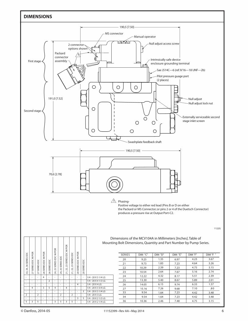
DIMENSIONS
1122G
SERIES DIM "C" DIM "D"
20
21
22
23
24
25
26
2733
34
36
9.25
9.73
10.29
10.54
12.22
13.30
14.05
15.169.54
9.54
10.36
1.35
1.83
2.39
2.64
4.32
5.40
6.15
7.26
1.64
1.64
2.46
DIM "E" DIM "F"
6.97
7.23
7.23
7.67
8.17
8.67
9.74
9.687.23
7.23
7.48
4.23
4.64
4.75
5.16
5.51
5.89
6.33
7.10
4.42
4.42
4.75
DIM "F "
3.67
3.26
3.15
2.74
2.39
2.01
1.57
.8 0
3.48
3.48
3.15
33, 3
4, 3
6 SE
RIES
ED
C
27 S
ERIE
S ED
C W
/PO
R
27 S
ERIE
S ED
C
26 S
ERIE
S ED
C W
/PO
R
26 S
ERIE
S ED
C
24, 2
5 SE
RIES
ED
C W
/PO
R
24, 2
5 SE
RIES
ED
C
21, 2
2, 2
3 SE
RIES
ED
C W
/PO
R
21, 2
2, 2
3 SE
RIES
ED
C
20 S
ERIE
S ED
C W
/PO
R
20 S
ERIE
S ED
C
1/4 - 20 X 5 1/4 LG
1/4 - 20 X 4 1/2 LG
1/4 - 20 X 4 LG
1/4 - 20 X 3 3/4 LG
1/4 - 20 X 3 1/4 LG
1/4 - 20 X 3 LG
1/4 - 20 X 2 1/2 LG
1/4 - 20 X 2 1/4 LG
-
2
5
-
-
-
-
-
-
-
3
-
-
4
-
-
-
2
5
-
-
-
-
-
4
-
-
-
-
3
-
-
-
-
-
2
-
5
-
-
-
-
3
-
-
4
-
-
-
2
5
-
-
-
-
-
-
-
3
-
-
4
-
-
-
2
5
-
-
-
-
-
-
-
-
-
4
-
-
3
-
-
-
-
-
-
2
5
Dimensions of the MCV104A in Millimeters [Inches]. Table of Mounting Bolt Dimensions, Quantity and Part Number by Pump Series.
Packard connectorassembly
2 connector options shown
MS connector Manual operator
Null adjust access screw
Sa )b2—FNU 81—61/9 .fer( 6— C415J e
Pilot pressure guage port (2 places)
Null adjust
Externally serviceable second stage inlet screen
Swashplate feedback shaft
Null adjust lock nut
Intrinsically safe device enclosure grounding terminal
1 Phasing-Positive voltage to either red lead (Pins B or D on either the Packard or MS Connector; or pins 2 or 4 of the Duetsch Connector) produces a pressure rise at Output Port-C2.
1
190,5 [7.50]
191,0 [7.52]
190,5 [7.50]
70,6 [2.78]
First stage
Second stage
© Danfoss, 2014-05 11152399 • Rev AA • May 2014 6
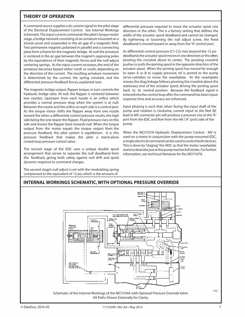
INTERNAL WORKINGS SCHEMATIC, WITH OPTIONAL PRESSURE OVERRIDE
THEORY OF OPERATION
Schematic of the Internal Workings of the MCV104A with Optional Pressure Override Valve. Oil Paths Shown Externally for Clarity.
1302
© Danfoss, 2014-05 11152399 • Rev AA • May 2014 7
A command source supplies a dc current signal to the pilot stage of the Electrical Displacement Control. See Internal Workings Schematic. The input current commands the pilot’s torque motor stage, a bridge network consisting of an armature mounted on a torsion pivot and suspended in the air gap of a magnetic field. Two permanent magnets polarized in parallel and a connecting plate form a frame for the magnetic bridge. At null the armature is centered in the air gap between the magnet’s opposing poles by the equivalence of their magnetic forces and the null-adjust centering springs. As the input current increases, the end of the armature becomes biased either north or south, depending on the direction of the current. The resulting armature movement is determined by the current, the spring constant, and the differential pressure feedback forces, explained next.
The magnetic bridge output, flapper torque, in turn controls the hydraulic bridge ratio. At null, the flapper is centered between two nozzles. Upstream from each nozzle is an orifice which provides a normal pressure drop when the system is at null. Between the nozzle and the orifice on each side is a control port. As the torque motor shifts the flapper away from one nozzle toward the other, a differential control pressure results, the high side being the one nearer the flapper. Fluid pressure rises on this side and moves the flapper back towards null. When the torque output from the motor equals the torque output from the pressure feedback, the pilot system is equilibrium. It is this pressure feedback that makes the pilot a stand-alone closed-loop pressure control valve.
The second stage of the EDC uses a unique double spool arrangement that serves to separate the null deadband from the feedback, giving both safety against null drift and quick dynamic response to command charges.
The second stage’s null adjust is set with the modulating spring compressed to the equivalent of 12 psi, which is the amount of
differential pressure required to move the actuator spool one direction or the other. This is a factory setting that defines the width of the actuator spool deadband and cannot be changed. By tightening or loosening the null adjust screw, the fixed deadband is moved toward or away from the “A” control port.
As differential control pressure (C1-C2) rises beyond the 12 psi deadband, the actuator spool moves in one direction or the other, pivoting the crosslink about its center. The pivoting crosslink pushes or pulls the porting spool in the opposite direction of the actuator spool. When the porting spool has moved far enough to open A or B to supply pressure, oil is ported to the pump servo-cylinders to move the swashplate. As the swashplate moves, the drag linkage follows, pivoting the crosslink about the stationary end of the actuator spool, driving the porting spool back to its neutral position. Because the feedback signal is entered into the control loop after the command has been input, response time and accuracy are enhanced.
Input phasing is such that, when facing the input shaft of the pump and rotation is clockwise, current input to the Red (B) lead or MS connector pin will produce a pressure rise at the “A” port from the EDC and flow from the left (’A” port) side of the pump.
When the MCV107A Hydraulic Displacement Control - MV is used on a motor in conjunction with the pump-mounted EDC, a single electrical command can be used to control both devices. This is done by “staging” the HDC so that the motor swashplate starts to destroke just as the pump reaches full stroke. For further information, see technical literature for the MCV107A.
1.0
1.0
.75
.75
.5
.5
.25
.25
18
10
-10
-18
Swas
hpla
te a
ngle
(deg
rees
)
Time (second) 1.0
1.0
.75
.75
.5
.5
.25
.25
18
10
-10
-18
Swas
hpla
te a
ngle
(deg
rees
)
Time (second)
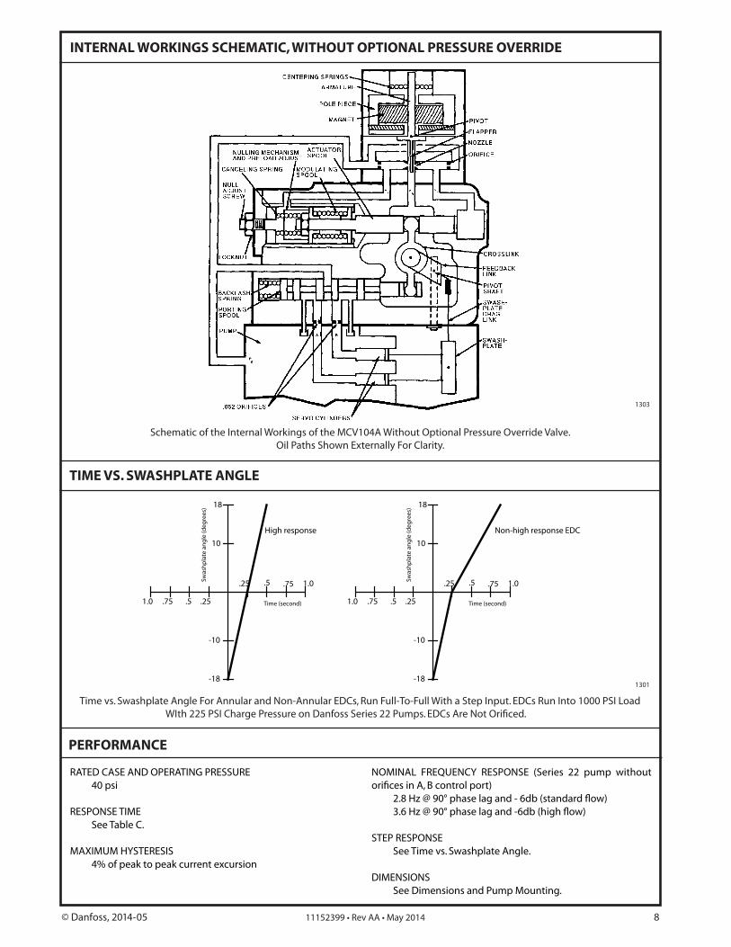
High response Non-high response EDC
INTERNAL WORKINGS SCHEMATIC, WITHOUT OPTIONAL PRESSURE OVERRIDE
Time vs. Swashplate Angle For Annular and Non-Annular EDCs, Run Full-To-Full With a Step Input. EDCs Run Into 1000 PSI Load
PERFORMANCE
Schematic of the Internal Workings of the MCV104A Without Optional Pressure Override Valve. Oil Paths Shown Externally For Clarity.
TIME VS. SWASHPLATE ANGLE
1303
1301
RATED CASE AND OPERATING PRESSURE 40 psi
RESPONSE TIME See Table C.
MAXIMUM HYSTERESIS 4% of peak to peak current excursion
NOMINAL FREQUENCY RESPONSE (Series 22 pump without
STEP RESPONSE See Time vs. Swashplate Angle.
DIMENSIONS See Dimensions and Pump Mounting.
© Danfoss, 2014-05 11152399 • Rev AA • May 2014 8
PERFORMANCE (continued)
ENVIRONMENTAL
SHOCK 50 g’s for 11 milliseconds. Three shocks in both directions
of the three mutually perpendicular axes for a total of 18 shocks.
VIBRATION Withstands a vibration test designed for mobile equipment
control consisting of two parts: 1. Cycling from 5 to 2000 Hz in each of the three axes.
2. Resonance dwell for one million cycles for each reso-nance point in each of the three axes.
Subject to acceleration levels of 1 g to 46 g’s. Acceleration level varies with frequency.
HUMIDITY After being placed in a controlled atmosphere of 95%
humidity at 49° C (120° F) for 10 days, the EDC will perform
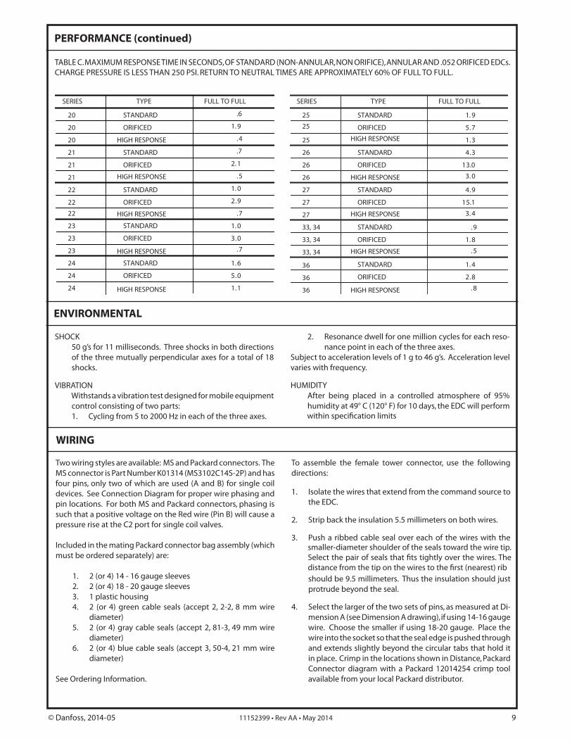
TABLE C. MAXIMUM RESPONSE TIME IN SECONDS, OF STANDARD (NON-ANNULAR, NON ORIFICE), ANNULAR AND .052 ORIFICED EDCs. CHARGE PRESSURE IS LESS THAN 250 PSI. RETURN TO NEUTRAL TIMES ARE APPROXIMATELY 60% OF FULL TO FULL.
Two wiring styles are available: MS and Packard connectors. The MS connector is Part Number K01314 (MS3102C14S-2P) and has four pins, only two of which are used (A and B) for single coil devices. See Connection Diagram for proper wire phasing and pin locations. For both MS and Packard connectors, phasing is such that a positive voltage on the Red wire (Pin B) will cause a pressure rise at the C2 port for single coil valves.
Included in the mating Packard connector bag assembly (which must be ordered separately) are: 1. 2 (or 4) 14 - 16 gauge sleeves 2. 2 (or 4) 18 - 20 gauge sleeves 3. 1 plastic housing 4. 2 (or 4) green cable seals (accept 2, 2-2, 8 mm wire
diameter) 5. 2 (or 4) gray cable seals (accept 2, 81-3, 49 mm wire
diameter) 6. 2 (or 4) blue cable seals (accept 3, 50-4, 21 mm wire
diameter)
See Ordering Information.
To assemble the female tower connector, use the following directions:
1. Isolate the wires that extend from the command source to the EDC.
2. Strip back the insulation 5.5 millimeters on both wires.
3. Push a ribbed cable seal over each of the wires with the
should be 9.5 millimeters. Thus the insulation should just protrude beyond the seal.
4. Select the larger of the two sets of pins, as measured at Di-mension A (see Dimension A drawing), if using 14-16 gauge wire. Choose the smaller if using 18-20 gauge. Place the wire into the socket so that the seal edge is pushed through and extends slightly beyond the circular tabs that hold it in place. Crimp in the locations shown in Distance, Packard Connector diagram with a Packard 12014254 crimp tool available from your local Packard distributor.
WIRING
SERIES TYPE FULL TO FULL
20
20
20
21
21
21
22
22
22
23
23
23
24
24
24
STANDARD
ORIFICED
HIGH RESPONSE
STANDARD
ORIFICED
STANDARD
ORIFICED
STANDARD
ORIFICED
STANDARD
ORIFICED
.6
1. 9
.4
.7
2. 1
.5
1. 0
2.9
.7
1. 0
3.0
.7
1. 6
5.0
1.1
HIGH RESPONSE
HIGH RESPONSE
HIGH RESPONSE
HIGH RESPONSE
25
25
25
26
26
26
27
27
27
33, 34
33, 34
33, 34
36
36
36
STANDARD
ORIFICED
HIGH RESPONSE
STANDARD
ORIFICED
STANDARD
ORIFICED
STANDARD
ORIFICED
STANDARD
ORIFICED
1. 9
5.7
1.3
4.3
13.0
3. 0
4.9
15.1
3. 4
.9
1. 8
.5
1. 4
2.8
.8
SERIES TYPE FULL TO FULL
HIGH RESPONSE
HIGH RESPONSE
HIGH RESPONSE
HIGH RESPONSE
© Danfoss, 2014-05 11152399 • Rev AA • May 2014 9
within specification limits
smaller-diameter shoulder of the seals toward the wire tip. Select the pair of seals that fits tightly over the wires. The distance from the tip on the wires to the first (nearest) rib
5. The distance from the back of the tangs to the furthest rib may not exceed 19.5 millimeters. See Distance, Packard Connector diagram.
6. Manually insert the assembled wires into the back end (large hole) of the plastic housing. Push until the wire de-tents with an audible click, then pull back slightly to ensure proper seating. (Observe the proper phasing of the wires when installing: Black wire to “A” hole, Red to “B”, Black to “C” and Red to “D”.) Terminals may be removed from the connector bodies with a Packard 12014012 removal tool.
WIRING (continued)
7. Swing the holder down into the detented position to trap the wires in the housing. The third rib should be sealed into the housing.
8. Plug the shroud connector from the valve into the tower connector just constructed. They are sealed with a double (or quadruple) plug seal over the double (or quadruple) barrel of the tower assembly. The two connector halves should detent into each other. See Connector Parts Identi-
1078A
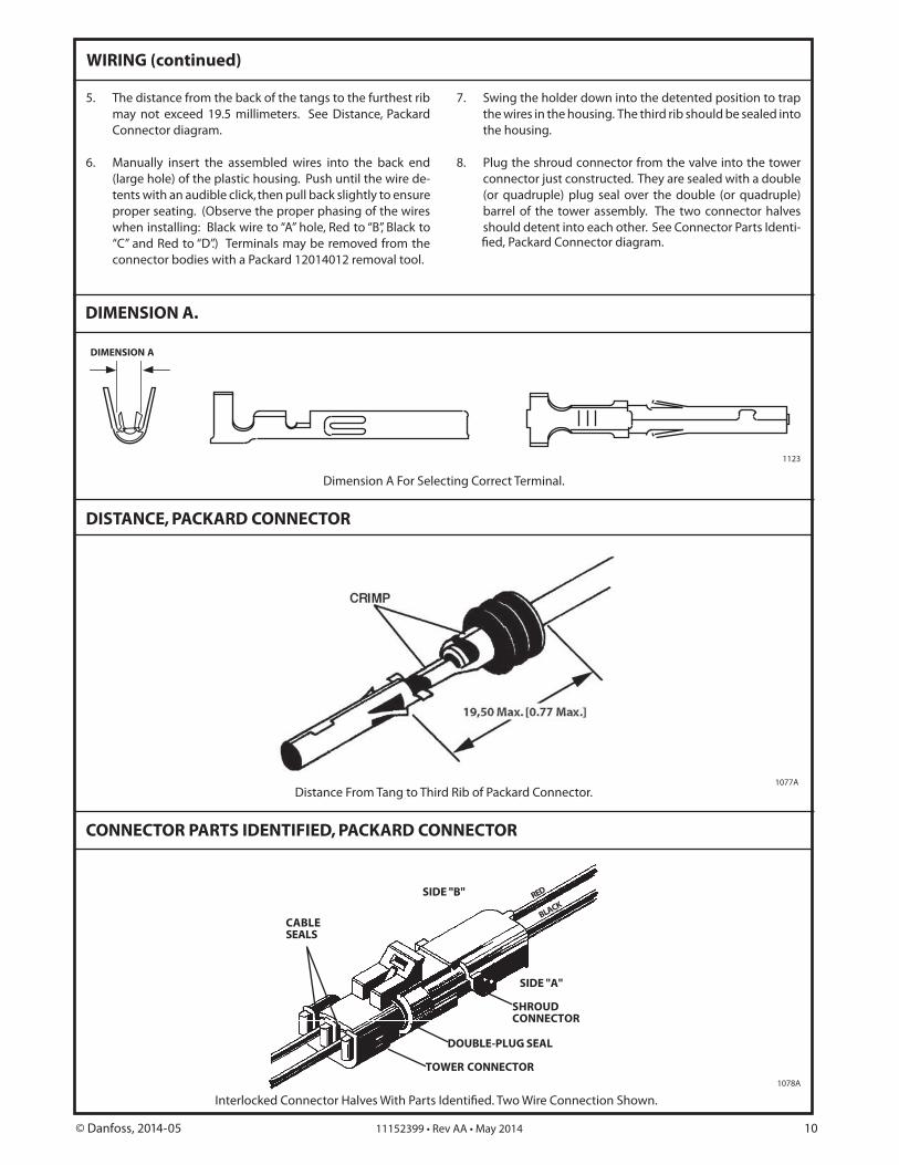
Distance From Tang to Third Rib of Packard Connector.1077A
DIMENSION A.
DISTANCE, PACKARD CONNECTOR
CONNECTOR PARTS IDENTIFIED, PACKARD CONNECTOR
DIMENSION A
1123
Dimension A For Selecting Correct Terminal.
CABLESEALS
SIDE "B" RED
BLACK
SHROUDCONNECTOR
SIDE "A"
DOUBLE-PLUG SEAL
TOWER CONNECTOR
fied, Packard Connector diagram.
Interlocked Connector Halves With Parts Identified. Two Wire Connection Shown.
© Danfoss, 2014-05 11152399 • Rev AA • May 2014 10
TROUBLESHOOTING STEPS
pressure when applying an electrical signal, actuate the
take the necessary safety precautions in the event full output pressure is reached. If output pressure is reached with the manual operator the problem may be electrical, in which case skip to step 5.
2. If the manual operator fails to achieve full output in both directions, ensure a minimum pump charge pressure.
within the PCP such as a lodged particle. Move to step 3 and check for the proper internal pressure reactions.
3. Checking the PCP internal pressures at neutral (null) and with a full rated electrical command can help isolate a problem. First shut off the hydraulic system then locate the two #6 SAE plugs in the sides of the PCP and place a 0-500 psi gage into each of these control ports. Once the gages are in place start the system. The gage reading will rise to approximately 40 ± 75 psi. If below 40 psi ensure
Readings should be within 10 psi or less of each other with no command signal (i.e., 55 and 64 psi). If greater than 15 psi of each other replace the PCP. If the problem is a pump creep in one direction and the gage readings are relatively close to within 10 psi of each other, restoring the PCP null is an option, proceed to step 4. Observe the gage readings while stroking the valve manually, then stroke it electrically. If either case fails to reach the proper minimum differential pressure (psid) level replace the PCP.
4. To restore the PCP null requires the hydraulic system to be running and a gage in each control port. Locate and remove the null access screw, a small amount of silicone oil will likely escape from this opening which is acceptable. Then insert a 3/32 allen wrench just beyond this opening into the adjustment set screw and very slowly adjust CW and/or CCW until gages are reading the same. Replace the
5. Checking for the proper electrical voltage or current requires a Volt Ohm Meter (VOM). Check voltage set meter to the Volt dc scale and place meter leads across the two wires going to the PCP coil. Voltage requirements may vary from one PCP model to another:
2.0 to 2.5 volts for single coil 14 to 85 mA models 2.0 to 3.0 volts for dual coil 22 to 130 mA models 4.0 to 15.0 volts for single coil 4 to 20 mA models When checking current, place the VOM in series between the
electrical controller and the valve. Set the meter to the dc amp scale and set the range to read mAs. The current level should reach the minimum. If the proper internal pressures are reached with the electrical signal (see Troubleshooting Step 1), there is likely a problem with the second stage the PCP is mounted to and it should be replaced.
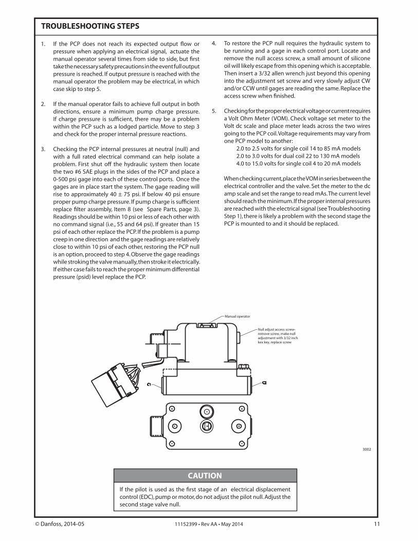
control (EDC), pump or motor, do not adjust the pilot null. Adjust the second stage valve null.
Manual operator
C2C1
Null adjust access screw-remove screw, make nulladjustment with 3/32 inchkex key, replace screw
3002
CAUTION
© Danfoss, 2014-05 11152399 • Rev AA • May 2014 11
INSTALLATION
TABLE D. TABLE D CORRELATES THE PUMP SERIES NUMBER WITH THE SERIES NUMBER STAMPED ON THE SIDE OF THE CONTROL FEEDBACK LINK PROTRUDING FROM THE CONTROL.
MOUNTING
Follow the procedure outlined below to attach the EDC to the pump.
REMOVING THE OLD HARDWARE
1. Thoroughly clean all external surfaces of the pump and control with steam or solvent. Blow dry.
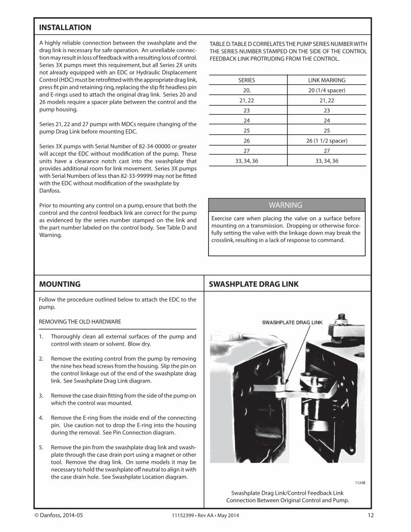
2. Remove the existing control from the pump by removing the nine hex head screws from the housing. Slip the pin on the control linkage out of the end of the swashplate drag link. See Swashplate Drag Link diagram.
which the control was mounted.
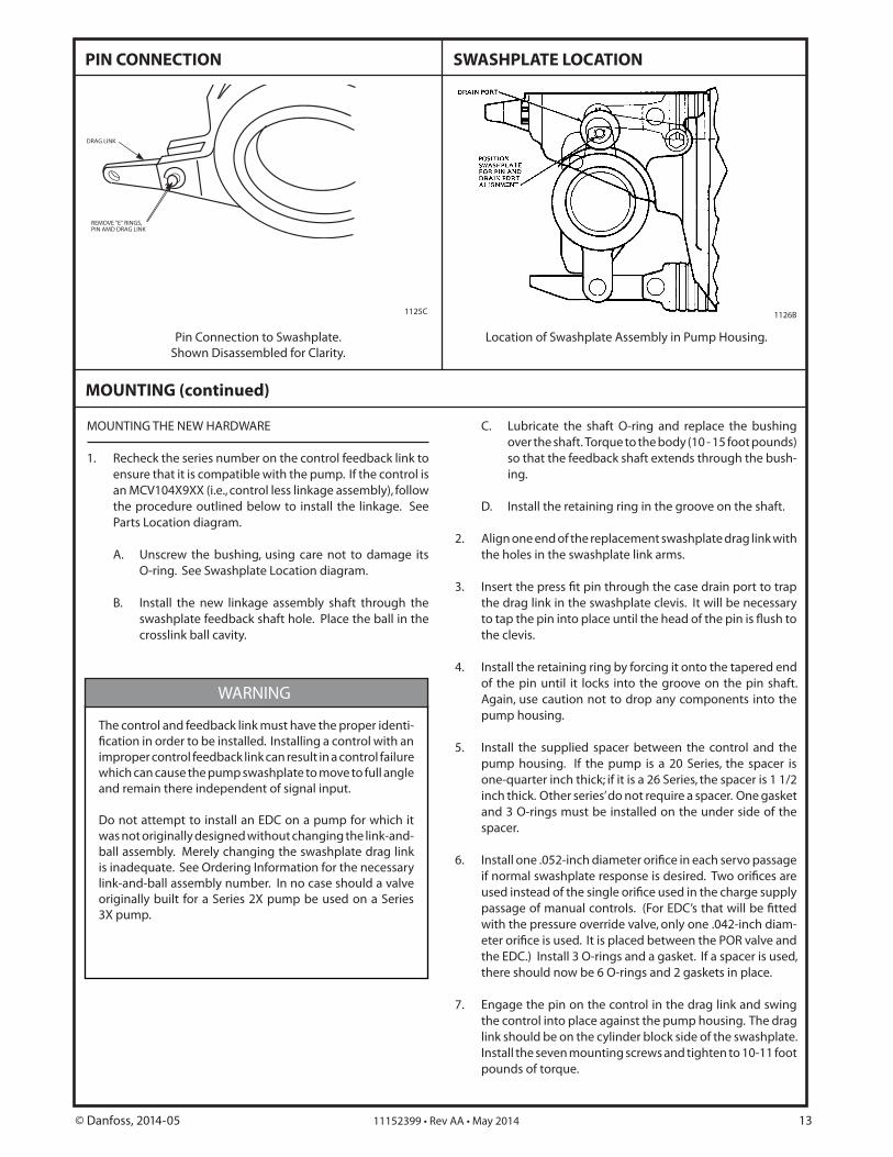
4. Remove the E-ring from the inside end of the connecting pin. Use caution not to drop the E-ring into the housing during the removal. See Pin Connection diagram.
5. Remove the pin from the swashplate drag link and swash-plate through the case drain port using a magnet or other tool. Remove the drag link. On some models it may be necessary to hold the swashplate off neutral to align it with the case drain hole. See Swashplate Location diagram.
SWASHPLATE DRAG LINK
A highly reliable connection between the swashplate and the drag link is necessary for safe operation. An unreliable connec-
.lortnoc fo ssol gnitluser a htiw kcabdeef fo ssol ni tluser yam noitSeries 3X pumps meet this requirement, but all Series 2X units not already equipped with an EDC or Hydraulic Displacement
and E-rings used to attach the original drag link. Series 20 and 26 models require a spacer plate between the control and the pump housing.
Series 21, 22 and 27 pumps with MDCs require changing of the pump Drag Link before mounting EDC.
Series 3X pumps with Serial Number of 82-34-00000 or greater
units have a clearance notch cast into the swashplate that provides additional room for link movement. Series 3X pumps
Danfoss.
Prior to mounting any control on a pump, ensure that both the control and the control feedback link are correct for the pump as evidenced by the series number stamped on the link and the part number labeled on the control body. See Table D and Warning.
SERIES LINK MARKING
20, 20 (1/4 spacer)
21, 22 21, 22
23 23
24 24
25 25
26 26 (1 1/2 spacer)
27 27
33, 34, 36 33, 34, 36
Swashplate Drag Link/Control Feedback Link Connection Between Original Control and Pump.
1124B
Exercise care when placing the valve on a surface before mounting on a transmission. Dropping or otherwise force-fully setting the valve with the linkage down may break the crosslink, resulting in a lack of response to command.
WARNING
© Danfoss, 2014-05 11152399 • Rev AA • May 2014 12
MOUNTING THE NEW HARDWARE
1. Recheck the series number on the control feedback link to ensure that it is compatible with the pump. If the control is an MCV104X9XX (i.e., control less linkage assembly), follow the procedure outlined below to install the linkage. See Parts Location diagram.
A. Unscrew the bushing, using care not to damage its O-ring. See Swashplate Location diagram.
B. Install the new linkage assembly shaft through the swashplate feedback shaft hole. Place the ball in the crosslink ball cavity.
PIN CONNECTION SWASHPLATE LOCATION
C. Lubricate the shaft O-ring and replace the bushing over the shaft. Torque to the body (10 - 15 foot pounds) so that the feedback shaft extends through the bush-ing.
D. Install the retaining ring in the groove on the shaft.
2. Align one end of the replacement swashplate drag link with the holes in the swashplate link arms.
the drag link in the swashplate clevis. It will be necessary
the clevis.
4. Install the retaining ring by forcing it onto the tapered end .tfahs nip eht no evoorg eht otni skcol ti litnu nip eht fo
Again, use caution not to drop any components into the pump housing.
5. Install the supplied spacer between the control and the pump housing. If the pump is a 20 Series, the spacer is one-quarter inch thick; if it is a 26 Series, the spacer is 1 1/2 inch thick. Other series’ do not require a spacer. One gasket and 3 O-rings must be installed on the under side of the spacer.
with the pressure override valve, only one .042-inch diam-
the EDC.) Install 3 O-rings and a gasket. If a spacer is used, there should now be 6 O-rings and 2 gaskets in place.
7. Engage the pin on the control in the drag link and swing the control into place against the pump housing. The drag
.etalphsaws eht fo edis kcolb rednilyc eht no eb dluohs knilInstall the seven mounting screws and tighten to 10-11 foot pounds of torque.
Pin Connection to Swashplate. Shown Disassembled for Clarity.
Location of Swashplate Assembly in Pump Housing.
1125C 1126B
MOUNTING (continued)
DRAG LINK
REMOVE "E" RINGS,PIN AMD DRAG LINK
The control and feedback link must have the proper identi-
improper control feedback link can result in a control failure which can cause the pump swashplate to move to full angle and remain there independent of signal input.
Do not attempt to install an EDC on a pump for which it was not originally designed without changing the link-and-ball assembly. Merely changing the swashplate drag link is inadequate. See Ordering Information for the necessary link-and-ball assembly number. In no case should a valve originally built for a Series 2X pump be used on a Series 3X pump.
WARNING
© Danfoss, 2014-05 11152399 • Rev AA • May 2014 13
PARTS LOCATION DRAWING
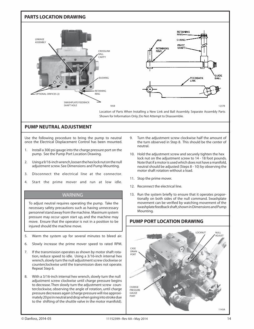
Location of Parts When Installing a New Link and Ball Assembly. Separate Assembly Parts Shown for Information Only; Do Not Attempt to Disassemble.
1858SWASHPLATE FEEDBACK SHAFT HOLE
RETAININGRING
BUSHING
CROSSLINKBALLCAVITY
OPTIONAL ORIFICES (2)
LINKAGEASSEMBLY
1237B
Use the following procedure to bring the pump to neutral once the Electrical Displacement Control has been mounted.
1. Install a 300 psi gauge into the charge pressure port on the pump. See the Pump Port Location Drawing.
2. Using a 9/16-inch wrench, loosen the hex lock nut on the null adjustment screw. See Dimensions and Pump Mounting.
3. Disconnect the electrical line at the connector.
4. Start the prime mover and run at low idle.
5. Warm the system up for several minutes to bleed air.
6. Slowly increase the prime mover speed to rated RPM.
7. If the transmission operates as shown by motor shaft rota-tion, reduce speed to idle. Using a 3/16-inch internal hex wrench, slowly turn the null adjustment screw clockwise or
.etarepo ton seod noissimsnart eht litnu esiwkcolcretnuocRepeat Step 6.
8. With a 3/16-inch internal hex wrench, slowly turn the null adjustment screw clockwise until charge pressure begins to decrease. Then slowly turn the adjustment screw coun-terclockwise, observing the angle of rotation, until charge pressure decreases again (charge pressure will rise approxi-mately 20 psi in neutral and drop when going into stroke due to the shifting of the shuttle valve in the motor manifold).
9. Turn the adjustment screw clockwise half the amount of the turn observed in Step 8. This should be the center of neutral.
10. Hold the adjustment screw and securely tighten the hex lock nut on the adjustment screw to 14 - 18 foot pounds. Note that if a motor is used which does not have a manifold, neutral should be adjusted (Steps 8 - 10) by observing the motor shaft rotation without a load.
11. Stop the prime mover.
12. Reconnect the electrical line.
tionally on both sides of the null command. Swashplate
swashplate feedback shaft, shown in Dimensions and Pump Mounting.
To adjust neutral requires operating the pump. Take the necessary safety precautions such as having unnecessary personnel stand away from the machine. Maximum system pressure may occur upon start up, and the machine may move. Ensure that the operator is not in a position to be injured should the machine move.
PUMP NEUTRAL ADJUSTMENT
PUMP PORT LOCATION DRAWING
CHARGEPRESSUREGAUGEPORT
CASEDRAINPORT
LOCKNUT NULLADJUST
1143A
WARNING
© Danfoss, 2014-05 11152399 • Rev AA • May 2014 14
REPLACING V7058 WITH MCV104 FOR S20 PV
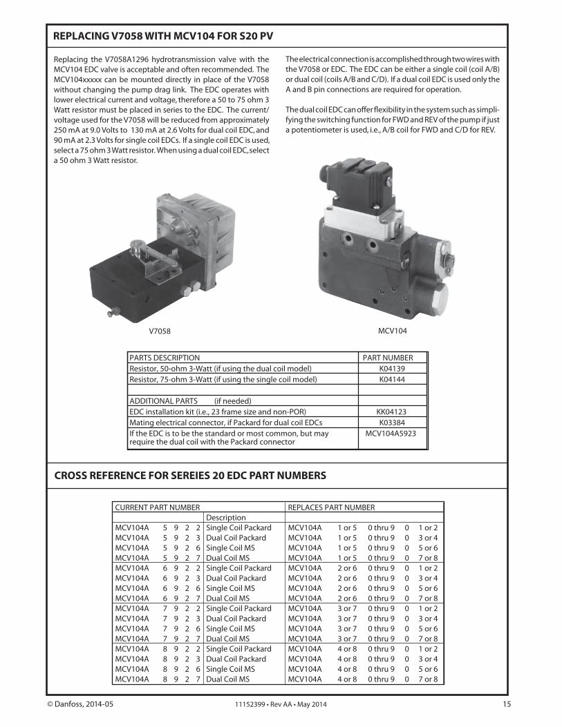
Replacing the V7058A1296 hydrotransmission valve with the MCV104 EDC valve is acceptable and often recommended. The MCV104xxxxx can be mounted directly in place of the V7058 without changing the pump drag link. The EDC operates with lower electrical current and voltage, therefore a 50 to 75 ohm 3 Watt resistor must be placed in series to the EDC. The current/voltage used for the V7058 will be reduced from approximately 250 mA at 9.0 Volts to 130 mA at 2.6 Volts for dual coil EDC, and 90 mA at 2.3 Volts for single coil EDCs. If a single coil EDC is used, select a 75 ohm 3 Watt resistor. When using a dual coil EDC, select a 50 ohm 3 Watt resistor.
The electrical connection is accomplished through two wires with the V7058 or EDC. The EDC can be either a single coil (coil A/B) or dual coil (coils A/B and C/D). If a dual coil EDC is used only the A and B pin connections are required for operation.
fying the switching function for FWD and REV of the pump if just a potentiometer is used, i.e., A/B coil for FWD and C/D for REV.
MCV104V7058
CROSS REFERENCE FOR SEREIES 20 EDC PART NUMBERS
CURRENT PART NUMBER REPLACES PART NUMBERDescription
MCV104A 5 9 2 2 Single Coil Packard MCV104A 1 or 5 0 thru 9 0 1 or 2MCV104A 5 9 2 3 Dual Coil Packard MCV104A 1 or 5 0 thru 9 0 3 or 4MCV104A 5 9 2 6 Single Coil MS MCV104A 1 or 5 0 thru 9 0 5 or 6MCV104A 5 9 2 7 Dual Coil MS MCV104A 1 or 5 0 thru 9 0 7 or 8MCV104A 6 9 2 2 Single Coil Packard MCV104A 2 or 6 0 thru 9 0 1 or 2MCV104A 6 9 2 3 Dual Coil Packard MCV104A 2 or 6 0 thru 9 0 3 or 4MCV104A 6 9 2 6 Single Coil MS MCV104A 2 or 6 0 thru 9 0 5 or 6MCV104A 6 9 2 7 Dual Coil MS MCV104A 2 or 6 0 thru 9 0 7 or 8MCV104A 7 9 2 2 Single Coil Packard MCV104A 3 or 7 0 thru 9 0 1 or 2MCV104A 7 9 2 3 Dual Coil Packard MCV104A 3 or 7 0 thru 9 0 3 or 4MCV104A 7 9 2 6 Single Coil MS MCV104A 3 or 7 0 thru 9 0 5 or 6MCV104A 7 9 2 7 Dual Coil MS MCV104A 3 or 7 0 thru 9 0 7 or 8MCV104A 8 9 2 2 Single Coil Packard MCV104A 4 or 8 0 thru 9 0 1 or 2MCV104A 8 9 2 3 Dual Coil Packard MCV104A 4 or 8 0 thru 9 0 3 or 4MCV104A 8 9 2 6 Single Coil MS MCV104A 4 or 8 0 thru 9 0 5 or 6MCV104A 8 9 2 7 Dual Coil MS MCV104A 4 or 8 0 thru 9 0 7 or 8
PARTS DESCRIPTION PART NUMBERResistor, 50-ohm 3-Watt (if using the dual coil model) K04139Resistor, 75-ohm 3-Watt (if using the single coil model) K04144
ADDITIONAL PARTS (if needed)EDC installation kit (i.e., 23 frame size and non-POR) KK04123Mating electrical connector, if Packard for dual coil EDCs K03384If the EDC is to be the standard or most common, but may require the dual coil with the Packard connector
MCV104A5923
© Danfoss, 2014-05 11152399 • Rev AA • May 2014 15
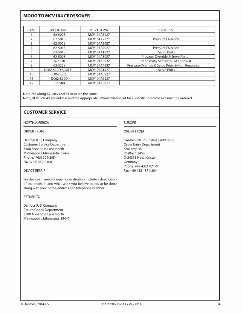
MOOG TO MCV104 CROSSOVER
Note, the Moog 62-xxxx and 63-xxxx are the same.
ITEM MOOG P/N MCV104 P/N FEATURES1 62-500B MCV104A59272 62-501B MCV104A7927 Pressure Override3 62-502B MCV104A59274 62-504B MCV104A7927 Pressure Override5 62-507B MCV104A1927 Servo Ports6 62-509B MCV104A3927 Pressure Override & Servo Ports7 62K518 MCV104A5932 Intrinsically Safe with FM approval8 62-522B MCV104A4927 Pressure Override & Servo Ports & High Response9 D062-512D,E, OR F MCV104A1927 Servo Ports
10 E062-562 MCV104A592711 D062-862D MCV104A592712 63-500 MCV104A5927
CUSTOMER SERVICE
NORTH AMERICA
ORDER FROM
Danfoss (US) CompanyCustomer Service Department3500 Annapolis Lane NorthMinneapolis, Minnesota 55447Phone: (763) 509-2084Fax: (763) 559-0108
DEVICE REPAIR
For devices in need of repair or evaluation, include a description of the problem and what work you believe needs to be done along with your name, address and telephone number.
RETURN TO
Danfoss (US) CompanyReturn Goods Department3500 Annapolis Lane NorthMinneapolis, Minnesota 55447
EUROPE
ORDER FROM
Danfoss (Neumünster) GmbH& Co.Order Entry DepartmentKrokamp 35Postfach 2460 D-24531 NeumünsterGermanyPhone: +49 4321 871-0Fax: +49 4321 871-284
© Danfoss, 2014-05 11152399 • Rev AA • May 2014 16