Embed Size (px)
Citation preview

MAGUIRE PRODUCTS INC. PUMPS
Series MDA® Progressive Cavity Drum Pump
with Automatic Speed Control
INSTRUCTION MANUAL
Copyright © Maguire Products, Inc. 2010

M A G U I R E P R O D U C T S , I N C .
Edition: March 30, 2010 2
S e r i e s M D A ®
M A G U I R E P R O D U C T S , I N C .
Edition: March 30, 2010 3
S e r i e s M D A ®
Maguire Products Inc. Model MDA
PROGRESSIVE CAVITY DRUM PUMP With AUTOMATIC SPEED CONTROL
Table of Contents
Principle of Pump Operation ___________________________________ 5
Principle of Controller Operation________________________________ 6
Description of Controls _______________________________________ 7
Start-up Procedure __________________________________________ 10
Formulas for Setting the Counter ______________________________ 11
Three-Step Disassembly of Pump ______________________________ 12
Maximum Output Specifications _______________________________ 13
Troubleshooting Loss of Color ________________________________ 14
Troubleshooting Controller Problems __________________________ 15
In-House Repairs____________________________________________ 18
Three Tiered Stand Instructions _______________________________ 20
Warranty __________________________________________________ 21
Technical Support and Contact Information _____________________ 22

M A G U I R E P R O D U C T S , I N C .
Edition: March 30, 2010 4
S e r i e s M D A ®
Copyright © 2010 Maguire Products Inc. The information contained within this manual including any translations thereof, is the property of Maguire Products Inc. and may not be reproduced, or transmitted in any form or by any means without the express written consent of Maguire Products Inc. To every person concerned with use and maintenance of the Model MDA Progressive Cavity Drum Pump with Automatic Speed Control it is recommended to read thoroughly these operating instructions. Maguire Products Inc. accepts no responsibility or liability for damage or malfunction of the equipment arising from non-observance of these operating instructions. To avoid errors and to ensure trouble-free operation, it is essential that these operating instructions are read and understood by all personnel who are to use the equipment. Should you have problems or difficulties with the equipment, please contact Maguire Products Inc. or your local Maguire distributor. These operating instructions only apply to the equipment described within this manual. For the latest revision of this manual, visit www.maguire.com Manufacturer’s Contact Information Maguire Products Inc. 11 Crozerville Road Aston, PA. 19014 Phone: 610.459.4300 Fax: 610.459.2700 Website: http://www.maguire.com
Email: [email protected]
M A G U I R E P R O D U C T S , I N C .
Edition: March 30, 2010 5
S e r i e s M D A ®
PRINCIPLE OF PROGRESSIVE CAVITY PUMP OPERATION Metering is accomplished by way of a positive displacement progressive cavity or rotary screw pump. A progressive cavity pump consists of a single helix steel screw, called a rotor, rotating within a double helix hollow stator constructed of an elastomer material such as viton or EPDM rubber. The rotation of the rotor within the fixed stator causes empty pockets or voids to travel or progress upward drawing liquid into one end and expelling it out the other end, producing a positive displacement pumping action. The double helix stat or produces an overlapping of voids resulting in smooth non-pulsating pumping action. The interference fit of the stator and rotor keeps slippage to a minimum. Pressures of 200 to 300 PSI are achievable before slippage or blow-by is apparent. The pumping unit is mounted at the end of a steel pipe which serves a double purpose. First, it positions the pumping unit at the bottom of the liquid drum totally immersed in the liquid while the controls and drive motor are positioned safely above the drum. Second, the pipe serves as a conduit in which the liquid flows up and out of the drum, exiting from the pipe through a quick-disconnect type coupling screwed into the side of the bearing-seal assembly at the top. The drive motor is coupled to a 1/2" drive shaft by way of a "Lovejoy" spider type shaft coupling. This coupling allows for easy removal of the motor and controls from the pumping unit. The 1/2" shaft passes through a machined celcon plastic adaptor unit, which contains a shaft positioning bearing and rotary-seal assembly. The lower end of this shaft is pinned to the rotor portion of the pump. The pumping unit itself is available in several different materials of construction. Viton for the stator and chrome plated steel for the rotor have been selected as the standard materials of construction for the Plastics Industry. Six different pump sizes coupled to several different motor sizes are available, providing an overall output range of from less than one CC per minute to over 60 gallons per hour.

M A G U I R E P R O D U C T S , I N C .
Edition: March 30, 2010 6
S e r i e s M D A ®
PRINCIPLE OF CONTROLLER OPERATION The MAGUIRE Digital Controller provides the precise speed regulation and metering control necessary to assure absolute accuracy over color usage. The Controller signal cord is plugged into an outlet that is energized only when the process machine screw runs. During each screw return cycle, the motor runs and color is metered into the throat of the process machine. Since metering rate is directly related to motor output shaft rotation, accuracy is obtained by controlling the exact degree of rotation of the drive motor. The unique Maguire Products Digital Controller is designed to do this with precision. Our standard Model divides each full motor rotation into 159 increments; each increment representing a small fraction of a gram of color being carefully measured out. The digital counter located on the face of the controller provides the means for predetermining the exact degree of rotation and, therefore, the precise amount of color that will be added during each cycle. When the pre-set count is reached, the motor will automatically shut off, ensuring that no excess color is metered. To determine the proper setting for the counter, a simple formula is used based on percent of color required and total shot weight in grams (or pounds per hour for extrusion applications). Motor speed is automatically controlled by the internal microprocessor to allow color metering to occur uniformly over the entire screw return cycle. The operator need not concern himself with motor speed adjustment. Changing cycle times or fluctuations in plant voltage are automatically detected and compensated for and, therefore, will have no effect on metering accuracy. The controller contains a 1/27 HP D.C. Permanent Magnet motor with variable speed control of from approximately 50 to 3000 RPMs. In the standard configuration, the motor is close coupled to a heavy duty gearbox with a reduction ratio of 53:1. Final output speed of the motor is, therefore, approximately 1 to 56 RPMs. As the motor turns, a "hall effect" pickup device on the motor sends 3 pulses per revolution to the microprocessor controlling it. The gearbox ratio of 53:1 means that 159 pulses (3x53) are received for every single revolution of the motor output shaft. The purpose of the thumbwheel switch is to pre-set the exact number of pulses that the motor is going to run before stopping. The microprocessor in the controller automatically multiplies the counter setting by a factor of 10. A setting of 16 on the counter will allow the controller to receive 160 pulses or run approximately 1 revolution before stopping. Regardless of how fast or how slow the motor runs, color metering will stop after 1 turn. In addition to this precise control of color quantity being metered, the microprocessor also controls motor speed using the same pulses for digital tachometer feedback. This ensures that motor speed is precisely regulated regardless of changing torque requirements or variations in plant voltage.
M A G U I R E P R O D U C T S , I N C .
Edition: March 30, 2010 7
S e r i e s M D A ®
DESCRIPTION OF CONTROLS
1. CYCLE-OFF-CONTINUOUS SWITCH CYCLE: The controller will meter a given quantity of color and will shut off for the remainder of the cycle. Quantity metered is controlled by the setting of the thumbwheel switch. In this mode, motor speed is automatically adjusted by the internal microprocessor based on the time length of the previous cycle and the setting of the counter. A speed is selected that will allow the feeder to stop approximately 1/2 second before the cycle ends. OFF: Will prevent the controller from running and will remove power to the computer controls. CONTINUOUS: The controller will run continuously as long as 110 volt power is present at the controller power cord. Speed is controlled by and directly follows the setting of the thumbwheel switch. Energizing the "cycle" cord has no effect -with one exception; if the RANGE switch is in the LOW resolution position (turned to the right) the motor will ONLY run when the SIGNAL cord is energized.
2. MOTOR FORWARD/REVERSE SWITCH
This switch should be in the FORWARD position for all normal operation. Holding the switch down in the REVERSE position will cause the controller motor to run backwards. In LIQUID COLOR pumps, this will cause the liquid color in the tubing to be returned to its source.
3. THUMBWHEEL SWITCHES
In the CYCLE mode, the thumbwheel switch setting controls the amount of color metered per cycle. In the CONTINUOUS mode, the setting determines the RPMs of the motor output shaft.

M A G U I R E P R O D U C T S , I N C .
Edition: March 30, 2010 8
S e r i e s M D A ®
4. MODE SWITCH The Mode Switch allows several SPECIAL functions. Located in the upper right corner of the control panel, it can be turned with a small screwdriver. NORMAL (mid position) All functions work as described elsewhere. Approximately 1/16 turn of the motor can be expected for every count on the counter or 63 turns of the motor for the maximum setting of 999. (This relationship may vary with non-standard models). FRACTIONAL (left position) CYCLE MODE: If very small metered amounts are required and calculated settings are 10 or less, these settings may not give you the fine resolution of control that you desire. Turning the Range Switch to the FRACTIONAL position will shift the display left one dig it with a decimal point appearing between the middle and last digit. Display format will be (##.#) so that fractional numbers can be set on the counter. A maximum of about 6 turns will result from the maximum setting of 99.9. Thus, to accomplish the same output as before, you would use a setting such as 030 instead of 003, resulting in a display of "03.0" instead of "003". CONTINUOUS MODE: no effect CALIBRATION (right position) CYCLE MODE: This position will force ONE cycle to run for 100 counts at a speed of about 20 RPMs. The SIGNAL cord need not be energized. When calculating METERING RATES for each color you run, this switch will force the controller to run a proper CALIBRATED output. This output in grams is used in the SETTING formula. CONTINUOUS MODE: The motor will ONLY run when the SIGNAL cord is energized. In the other positions, NORMAL and FRACTIONAL, CONTINUOUS mode will run the motor WITHOUT the SIGNAL cord being energized.

M A G U I R E P R O D U C T S , I N C .
Edition: March 30, 2010 9
S e r i e s M D A ®
5. DISPLAY WINDOW In the CYCLE mode, the window will display a numerical countdown beginning with the three digit counter setting and proceeding to zero. In the CONTINUOUS mode, the window will display motor RPMs. Flashing of this display at half second intervals indicates that the motor is not running at the speed necessary to deliver all the color in the time allotted (See TROUBLESHOOTING section for more information). The presence of a decimal point in the display means the range switch is turned to the FRACTIONAL position.
6. SIGNAL LIGHT
The Signal Light indicates power is present at the signal cord; in other words, the process machine screw is turning.
7. MOTOR LIGHT
The Motor Light indicates the computer processor is outputting a D.C. voltage to the controller motor; in other words, the motor is turning.
M A G U I R E P R O D U C T S , I N C .
Edition: March 30, 2010 10
S e r i e s M D A ®
START-UP PROCEDURE
1. Place color drum next to process machine.
2. Remove 2" bung hole plug and install drum pump into drum through this opening. Insert pump adaptor fitting into bung hole. Bottom of pump assembly should be allowed to rest squarely on the bottom of the drum. Tighten clamping bolts in adaptor to positively lock drum pump and adaptor together to match the size of the drum.
3. There should be provision for attaching the poly-tubing to the process machine so as to
allow color to be metered directly over the feed section of the screw, or into a pre-mixer if one is installed. Assuming provisions have been made, attach or install the poly-tubing to the process machine as required.
4. Plug the "CONTINUOUS POWER" cord into a standard 110 volt continuous power source.
5. Assuming pump is not already primed, set counter to 90 and switch to "CONTINUOUS"
until entire pump and color line is primed.
6. Plug "SIGNAL" cord into outlet that is energized only when the screw is turning. Signal voltages from 24 to 240 can be handled. The main switch should now be set on "CYCLE". The "screw return" time and associated "SIGNAL ON" time must be at least one (1) second. If you are not sure that this is always the case than it is advisable to select another source of power for the signal. INJECTION time would be an excellent choice for a signal when screw return time is extremely short. For very short overall cycle times, the CLAMP CLOSE time is usually the longest signal time available. When screw return times are shorter than 1 second, use the INJECTION circuit or CLAMP CLOSE circuit to provide power to the SIGNAL cord.
7. Using the formula provided in this manual set the counter to the proper setting for the
particular part you are molding.
8. Your controller will now cycle on and off each time the process machine screw is cycled. Motor speed will adjust automatically. Remember - experience may show that a somewhat higher or lower counter setting is required to produce the exact depth of color desired. Once the proper setting is determined, it should be recorded for future reference.
M A G U I R E P R O D U C T S , I N C .
Edition: March 30, 2010 11
S e r i e s M D A ®
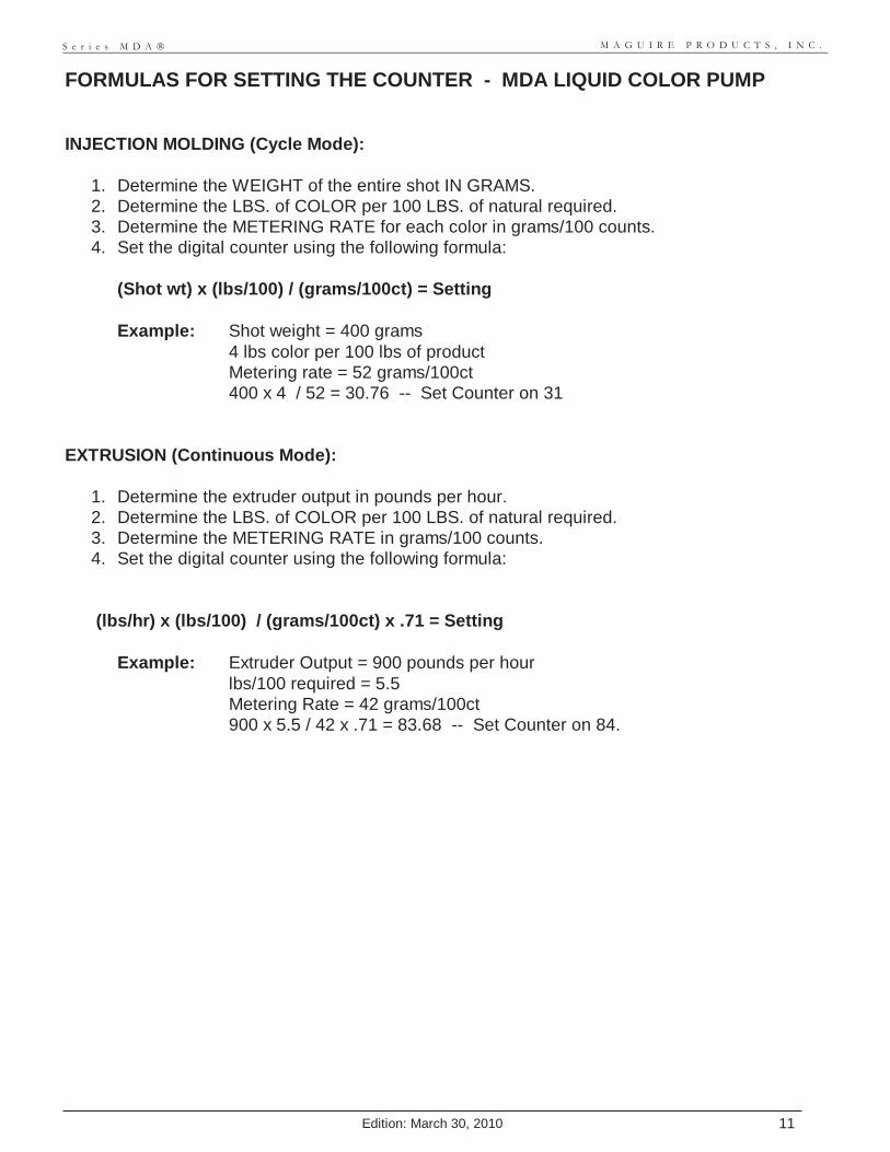
FORMULAS FOR SETTING THE COUNTER - MDA LIQUID COLOR PUMP INJECTION MOLDING (Cycle Mode):
1. Determine the WEIGHT of the entire shot IN GRAMS. 2. Determine the LBS. of COLOR per 100 LBS. of natural required. 3. Determine the METERING RATE for each color in grams/100 counts. 4. Set the digital counter using the following formula:
(Shot wt) x (lbs/100) / (grams/100ct) = Setting Example: Shot weight = 400 grams
4 lbs color per 100 lbs of product Metering rate = 52 grams/100ct 400 x 4 / 52 = 30.76 -- Set Counter on 31
EXTRUSION (Continuous Mode):
1. Determine the extruder output in pounds per hour. 2. Determine the LBS. of COLOR per 100 LBS. of natural required. 3. Determine the METERING RATE in grams/100 counts. 4. Set the digital counter using the following formula:
(lbs/hr) x (lbs/100) / (grams/100ct) x .71 = Setting
Example: Extruder Output = 900 pounds per hour lbs/100 required = 5.5 Metering Rate = 42 grams/100ct 900 x 5.5 / 42 x .71 = 83.68 -- Set Counter on 84.
M A G U I R E P R O D U C T S , I N C .
Edition: March 30, 2010 12
S e r i e s M D A ®
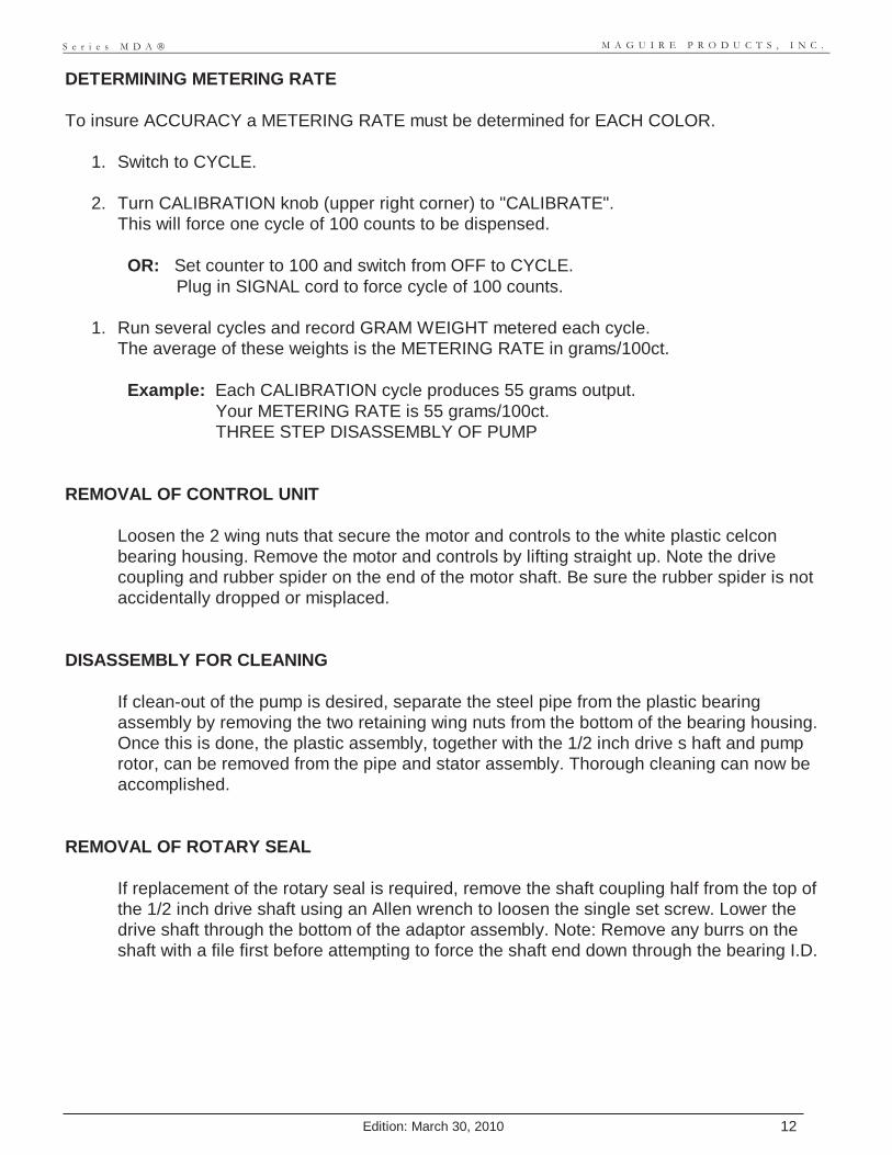
DETERMINING METERING RATE To insure ACCURACY a METERING RATE must be determined for EACH COLOR.
1. Switch to CYCLE.
2. Turn CALIBRATION knob (upper right corner) to "CALIBRATE". This will force one cycle of 100 counts to be dispensed. OR: Set counter to 100 and switch from OFF to CYCLE. Plug in SIGNAL cord to force cycle of 100 counts.
1. Run several cycles and record GRAM WEIGHT metered each cycle.
The average of these weights is the METERING RATE in grams/100ct. Example: Each CALIBRATION cycle produces 55 grams output. Your METERING RATE is 55 grams/100ct. THREE STEP DISASSEMBLY OF PUMP
REMOVAL OF CONTROL UNIT
Loosen the 2 wing nuts that secure the motor and controls to the white plastic celcon bearing housing. Remove the motor and controls by lifting straight up. Note the drive coupling and rubber spider on the end of the motor shaft. Be sure the rubber spider is not accidentally dropped or misplaced.
DISASSEMBLY FOR CLEANING
If clean-out of the pump is desired, separate the steel pipe from the plastic bearing assembly by removing the two retaining wing nuts from the bottom of the bearing housing. Once this is done, the plastic assembly, together with the 1/2 inch drive s haft and pump rotor, can be removed from the pipe and stator assembly. Thorough cleaning can now be accomplished.
REMOVAL OF ROTARY SEAL
If replacement of the rotary seal is required, remove the shaft coupling half from the top of the 1/2 inch drive shaft using an Allen wrench to loosen the single set screw. Lower the drive shaft through the bottom of the adaptor assembly. Note: Remove any burrs on the shaft with a file first before attempting to force the shaft end down through the bearing I.D.
M A G U I R E P R O D U C T S , I N C .
Edition: March 30, 2010 13
S e r i e s M D A ®
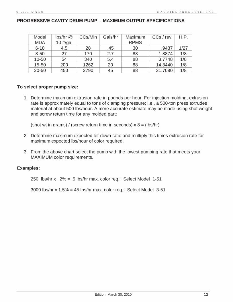
PROGRESSIVE CAVITY DRUM PUMP -- MAXIMUM OUTPUT SPECIFICATIONS
Model MDA
lbs/hr @ 10 #/gal
CCs/Min Gals/hr Maximum RPMS
CCs / rev H.P.
6-18 4.5 28 .45 30 .9437 1/27 8-50 27 170 2.7 88 1.8874 1/8
10-50 54 340 5.4 88 3.7748 1/8 15-50 200 1262 20 88 14.3440 1/8 20-50 450 2790 45 88 31.7080 1/8
To select proper pump size:
1. Determine maximum extrusion rate in pounds per hour. For injection molding, extrusion rate is approximately equal to tons of clamping pressure; i.e., a 500-ton press extrudes material at about 500 lbs/hour. A more accurate estimate may be made using shot weight and screw return time for any molded part: (shot wt in grams) / (screw return time in seconds) x 8 = (lbs/hr)
2. Determine maximum expected let-down ratio and multiply this times extrusion rate for
maximum expected lbs/hour of color required.
3. From the above chart select the pump with the lowest pumping rate that meets your MAXIMUM color requirements.
Examples:
250 lbs/hr x .2% = .5 lbs/hr max. color req.: Select Model 1-51 3000 lbs/hr x 1.5% = 45 lbs/hr max. color req.: Select Model 3-51

M A G U I R E P R O D U C T S , I N C .
Edition: March 30, 2010 14
S e r i e s M D A ®
TROUBLESHOOTING LOSS OF COLOR
1. Check that color supply is adequate by tipping drum of color slightly or observing level of color. Consider that if color level is nearing the bottom of the drum, air may have been sucked in momentarily and a considerable length of time would have passed before the loss of color would be evident at the process machine.
2. Check that the pump shaft is rotating the proper number of revolutions per cycle; on most
models 159 counts equals 10 turns of the pump rotor. Remember that the Range switch can alter this relationship so that 159 counts will equal 1 revolution. An incorrect relationship between counts and revolutions indicates an internal electronic problem. See #5 below.
3. Pump speed may exceed the flow characteristics of the liquid being pumped. Pump suction
alone is used to draw liquid into the pumping unit and only normal atmospheric pressure of 15 PSI is available to push liquid into the inlet end of the pump. Higher viscosity liquids do not flow as fast as lower viscosity liquids and may not be capable of flowing into the pump suction end as rapidly as pumping speed would dictate. To determine if the maximum possible flow rate is being exceeded, reduce counter setting by 50%. If output does not drop proportionally, viscosity is a problem. To solve this, you may:
(1) Specify a larger capacity pump. (2) Reformulate liquid color for lower viscosity.
M A G U I R E P R O D U C T S , I N C .
Edition: March 30, 2010 15
S e r i e s M D A ®
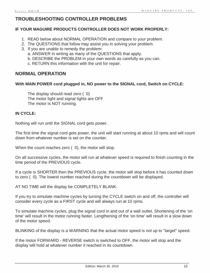
TROUBLESHOOTING CONTROLLER PROBLEMS IF YOUR MAGUIRE PRODUCTS CONTROLLER DOES NOT WORK PROPERLY:
1. READ below about NORMAL OPERATION and compare to your problem. 2. The QUESTIONS that follow may assist you in solving your problem. 3. If you are unable to remedy the problem:
a. ANSWER in writing as many of the QUESTIONS that apply. b. DESCRIBE the PROBLEM in your own words as carefully as you can. c. RETURN this information with the unit for repair.
NORMAL OPERATION With MAIN POWER cord plugged in, NO power to the SIGNAL cord, Switch on CYCLE:
The display should read zero ( 0) The motor light and signal lights are OFF The motor is NOT running.
IN CYCLE: Nothing will run until the SIGNAL cord gets power. The first time the signal cord gets power, the unit will start running at about 10 rpms and will count down from whatever number is set on the counter. When the count reaches zero ( 0), the motor will stop. On all successive cycles, the motor will run at whatever speed is required to finish counting in the time period of the PREVIOUS cycle. If a cycle is SHORTER then the PREVIOUS cycle, the motor will stop before it has counted down to zero ( 0). The lowest number reached during the countdown will be displayed. AT NO TIME will the display be COMPLETELY BLANK. If you try to simulate machine cycles by turning the CYCLE switch on and off, the controller will consider every cycle as a FIRST cycle and will always run at 10 rpms. To simulate machine cycles, plug the signal cord in and out of a wall outlet. Shortening of the 'on time' will result in the motor running faster. Lengthening of the 'on time' will result in a slow down of the motor speed. BLINKING of the display is a WARNING that the actual motor speed is not up to "target" speed. If the motor FORWARD - REVERSE switch is switched to OFF, the motor will stop and the display will hold at whatever number it reached in its countdown.
M A G U I R E P R O D U C T S , I N C .
Edition: March 30, 2010 16
S e r i e s M D A ®
Switching to OFF and then to FORWARD again during a countdown will cause a momentary increase in motor speed as the unit tries to 'catch up'. CYCLE TIME: The motor will start to run about 1/3 (.3) second after a signal is received. If the Signal is less than about 2/3 (.6) seconds long, then the motor will stop and the processor will not consider this as a valid cycle. No recalculation of motor speed will occur. If the signal is over 2/3 (.6) seconds long, then the motor will run for at least 2 seconds even if the signal goes away. This allows time for speed adjustments to occur. On longer cycles, over 2 seconds, the counter should count down to zero and the motor should stop within the 1/2 second before the end of the signal. If you are simulating cycles by plugging and unpluging the signal cord, it will be difficult to produce uniform motor speed and count down rates unless you carefully use a watch to produce uniform cycle times. If power to the signal cord ends before countdown is complete, the motor stops immediately and the number of counts remaining is held on the display. IN CONTINUOUS: The signal cord has no effect. The motor runs at a speed equal to the counter setting. If the setting is above the maximum speed possible, then the motor just runs at full speed and the display BLINKS. Full speed will display about '65' for 2 magnet models (most 3 and 6 roller pumps) and about '90' for all other models (Extrusion following models display about 180 at full speed). BLINKING of the display is NOT NORMAL except during speed changes. If the FORWARD - REVERSE switch is turned OFF, a display of one ( 1) will result and the motor will not run. ALL UNITS: If at any time should the processor become confused and fail to run the motor properly or display the proper numbers, the unit will 'restart' itself after a delay of about 4 seconds. BLINKING of the display means that actual motor speed is not up to "target" speed. This occurs normally when the motor is "ramping up" to speed or when you set too high a number on the counter resulting in a demand for a speed that the motor cannot achieve.

M A G U I R E P R O D U C T S , I N C .
Edition: March 30, 2010 17
S e r i e s M D A ®
ANSWER QUESTIONS as they apply YOUR COMPANY NAME:_______________________________ DATE:_______________ NAME of PERSON who saw or knows the problem:__________________________ CONTROLLER SERIAL NUMBER: ____________ Time in service: (new, 1 hour, 1 week, years, etc.) ____________ IF PROBLEM IS WITH OUTPUT SPECIFICATIONS as they apply: Injection molding, Shot weight: ____________ Extrusion, lbs/hour: ____________ Liquid color lbs/gal: ____________ Desired output (%): ____________ Viscosity of liquid color (thin, thick, etc.): ____________ Supply and delivery tube sizes and lengths, if not standard: ____________ IF PROBLEM IS ELECTRONIC FAILURE CIRCUMSTANCES of failure: During storm: ____________ On Monday morning start up: ____________ Same time as another malfunction in plant such as a fuse blowing on a nearby piece of equipment: ____________ Possibility of incorrect voltage (220): ____________ Possibility of low voltage condition (below 100): ____________ On power-up: ____________ OR after running for how many hours: ____________ Is problem intermittent: ____________ How often: ____________ TESTING results: Do other controllers fail under same circumstances: ____________ Does controller work when tested in another location: ____________ Does problem come and go: ____________ After how much time: ____________ IF PROBLEM IS ERRATIC OR INCORRECT OPERATION If running in CYCLE: What is the COUNTER SETTING: ____________ SCREW RETURN (signal) TIME in seconds: ____________ Are screw return times consistent from cycle to cycle: ____________ If not, list some consecutive screw return times: ________________________________________________ Is the problem only at certain settings: ____________ Does display start at the full counter setting at the start of each cycle (it should): ____________ Does the display BLINK during count down: ____________ Does it reach zero ( 0) before end of cycle: ____________ How long before: ____________ Does display ever go completely blank (it shouldn't): ____________ (it should always show a number or a zero except when blinking) Is the SIGNAL light lit during screw return time: ____________ Is the MOTOR light lit during this period of time: ____________ Is it counting down smoothly at a steady speed: ____________ If running too slow: what is actual motor output RPMs: ____________

M A G U I R E P R O D U C T S , I N C .
Edition: March 30, 2010 18
S e r i e s M D A ®
What count is displayed when it stops: ____________ If running too fast: How many seconds does it take to count down to zero: ____________ If running in CONTINUOUS: What is the COUNTER SETTING: ____________ EXTRUSION RATE: ____________ Does the display show the full counter setting: ____________ Does the display BLINK while running: ____________ Does the display drift: ____________ Over what range: ____________ Is the SIGNAL light lit: ____________ Is the MOTOR light lit: ____________ Is motor speed erratic: ____________ DESCRIBE the PROBLEM Most problems are apparent and easy to fix. However, the more information we have about what caused the problem, the more we can do to improve our product so that these problems do not occur in the future. In some cases we may NOT be able to duplicate YOUR particular problem in OUR testing facility. Describing the problem as CAREFULLY and as completely as possible will help us locate and correct any design weakness that might be responsible for the problems you are having. IN HOUSE REPAIRS
1. If a controller fails to respond properly to counter settings, cycle input signal, or on/off signals properly, you may make an inspection of the internal electronics. Work only in a relatively clean environment. Inspect all cable connections to be sure each is tight and that proper connection is being made by each individual wire and clip within each connector; individual wire clips can sometimes pull loose from the connector. Inspect all solder connections for broken wires or improper solder connections. Inspect the magnet holding cup on the rear of the motor. If this assembly should loosen, this will adversely affect motor control. Take care not to disturb or damage the electronic hall effect device that is attached to the rear of the motor. Repairs to printed circuit boards should not be attempted. Generally, if a component fails it indicates a condition that may have caused other components to fail as well. Boards should be returned to the factory for repair. A blown fuse on a circuit board usually indicates that other problems are present. A new fuse of similar size and rating may be substituted but if it blows again, the board should be returned to our factory for service. DO NOT EXCEED 5 AMPS on the board.
2. Flashing of the number display indicates that the motor is unable to run at the proper calculated speed. One reason for this may be that the counter setting is too high and the cycle time too short for the motor to complete the metering even at full rated speed. The other cause for the flashing display is that an obstruction is slowing the output shaft and the automatic torque limiting feature is slowing the motor intentionally.
M A G U I R E P R O D U C T S , I N C .
Edition: March 30, 2010 19
S e r i e s M D A ®
3. NO DISPLAY NUMBER at any time is usually a failed power supply. Be sure there is power to the unit. Check the fuse. There is a fuse on the circuit board; however, this fuse usually will not blow unless some other component on the board has failed. Replace only with a fuse of the same amp rating.
4. DISPLAY of ONE ( 1) in the CONTINUOUS MODE indicates that the processor is attempting to run the motor but is not picking up any RPM feedback from the armature. Check (a),(b),(c) and (d) below if the motor does not run. Check (e) if it does run.
a. Components may be blown out on the circuit board. A reading of zero (0) VOLTS at
the motor FORWARD - REVERSE switch would indicate this.
b. The FORWARD - REVERSE switch may be turned off or may be faulty.
c. Brushes on the motor may not be making proper contact with the armature. Sometimes brushes stick in their holders. A DC voltage at the motor leads without corresponding motor rotation would indicate this might be the problem. Removal of the brushes and light sanding of the brush sides will fix this.
d. The armature may be burned out. This will occur only with continuous overloading
and subsequent overheating. Circuit boards are designed to prevent this through a torque-limiting feature. Armatures that burn up leave a distinct odor in the control box.
e. If the motor is running but the display is still one ( 1), check the magnet holding disk
on the motor armature shaft. It should be secure and there should be about 1/16 inch space between the magnet holder and the electronic "hall effect" device on the back of the motor housing. Also check this electronic device for proper location. It must be positioned under the magnet cup and have no broken wire leads.
M A G U I R E P R O D U C T S , I N C .
Edition: March 30, 2010 20
S e r i e s M D A ®
Three Tiered Stand Instructions
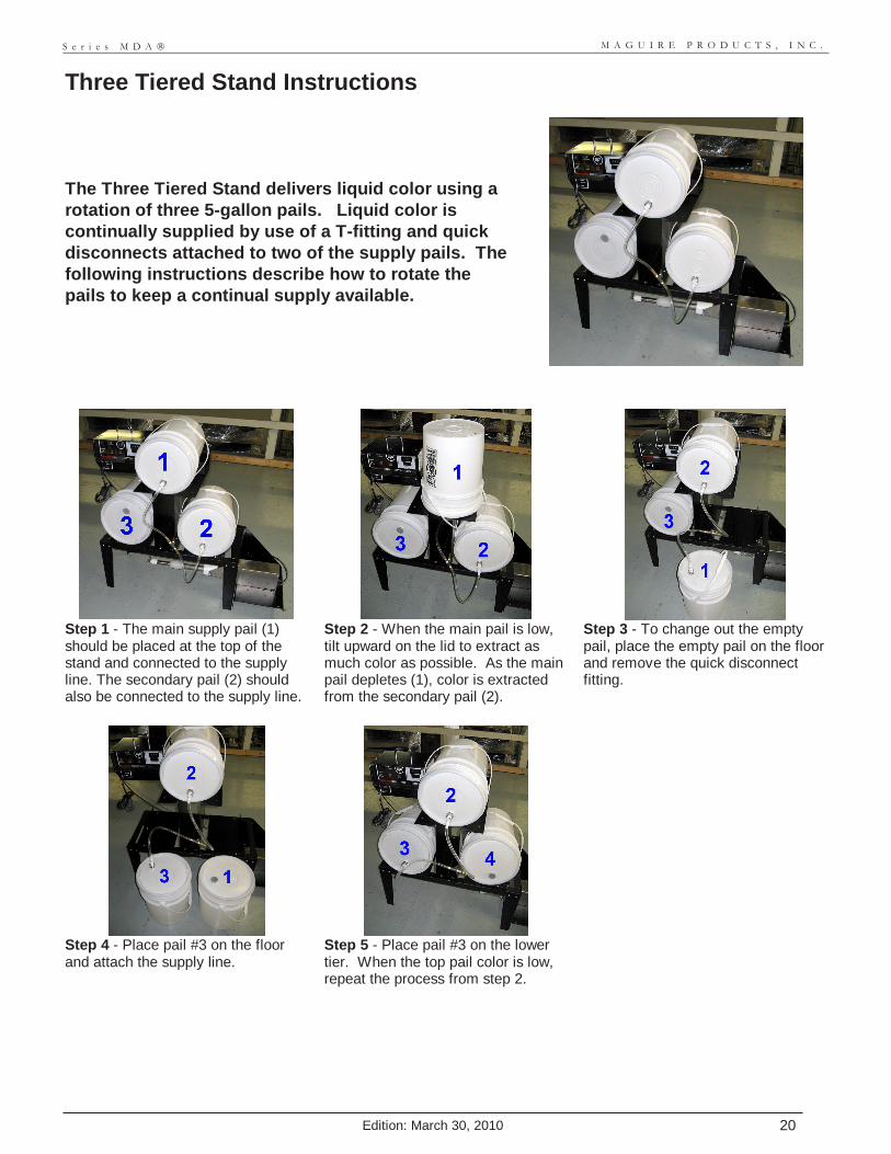
The Three Tiered Stand delivers liquid color using a rotation of three 5-gallon pails. Liquid color is continually supplied by use of a T-fitting and quick disconnects attached to two of the supply pails. The following instructions describe how to rotate the pails to keep a continual supply available.
Step 1 - The main supply pail (1) should be placed at the top of the stand and connected to the supply line. The secondary pail (2) should also be connected to the supply line.
Step 2 - When the main pail is low, tilt upward on the lid to extract as much color as possible. As the main pail depletes (1), color is extracted from the secondary pail (2).
Step 3 - To change out the empty pail, place the empty pail on the floor and remove the quick disconnect fitting.
Step 4 - Place pail #3 on the floor and attach the supply line.
Step 5 - Place pail #3 on the lower tier. When the top pail color is low, repeat the process from step 2.

M A G U I R E P R O D U C T S , I N C .
Edition: March 30, 2010 21
S e r i e s M D A ®
WARRANTY - Exclusive 5-Year MAGUIRE PRODUCTS offers one of the MOST COMPREHENSIVE WARRANTIES in the plastics equipment industry. We warrant each instrument and other articles of equipment manufactured by us to be free from defects in material and workmanship under normal use and service; excluding only those items listed below as 'EXCLUDED ITEMS'; our obligation under this warranty being limited to making good at its factory any instrument or other article of equipment which shall within FIVE (5) YEARS after delivery of such instrument or article of equipment to the original purchaser be returned intact to us, transportation charges prepaid, and which our examination shall disclose to our satisfaction to have been thus defective; this warranty being expressly in lieu of all other warranties expressed or implied
and of all other obligations or liabilities on our part, and MAGUIRE PRODUCTS neither assumes nor authorizes any other persons to assume for it any other liability in connection with the sale of its products. This warranty shall not apply to any instrument or other article of equipment which shall have been repaired or altered outside MAGUIRE PRODUCTS factory, unless such repair or alteration was, in our judgment, not responsible for the failure; nor which has been subject to misuse, negligence or accident, incorrect wiring by others, or installation or use not in accord with instructions furnished by the manufacturer. Our liability under this warranty will extend only to equipment that is returned to our factory in Aston, Pennsylvania. It should be noted, however, that we strive to satisfy our customers in whatever manner is deemed most expedient to overcome any problems they may have in connection with our equipment. EXCLUDED ITEMS The rotor and stator of the pumping unit are both subject to wear when abrasive pigments are being metered. An example would be TIO2, titanium dioxide, an extremely abrasive white pigment common in many color formulas. For this reason, our warranty on the rotor and stator is for ONE (1) year only. However, in most circumstances, you may reasonably expect these components to last much longer. A life expectancy of over five years is common.

M A G U I R E P R O D U C T S , I N C .
Edition: March 30, 2010 22
S e r i e s M D A ®
Technical Support and Contact Information
Maguire Products Inc. 11 Crozerville Road Aston, PA 19014 Tel: 610.459.4300 Fax: 610.459.2700 Email: [email protected] Web: www.maguire.com Maguire Europe Tame Park Tamworth Staffordshire B775DY UK Tel: + 44 1827 265 850 Fax: + 44 1827 265 855 Email: [email protected] Maguire Products Asia PTE LTD Main Office 15 Changi North Street 1 #01-15, I-Lofts Singapore 498765 Tel: 65 6848-7117 Fax: 65 6542-8577 E-mail: [email protected]