Embed Size (px)
Citation preview

Full file at http://testbank360.eu/solution-manual-modern-database-management-9th-edition-hoffer
Chapter 3 Modeling Data in the Organization
Chapter Overview
The purpose of this chapter is to present a detailed description of the entity-relationship model and the use of this tool within the context of conceptual data modeling. This chapter presents the basic entity-relationship (or E-R) model, while advanced features are presented in Chapter 4.
Chapter Objectives
Specific student learning objectives are included in the beginning of the chapter. From an instructor’s point of view, the objectives of this chapter are to:1. Emphasize the importance of understanding organizational data, and convince your
students that unless they can represent data unambiguously in logical terms, they cannot implement a database that will effectively serve the needs of management.
2. Present the E-R model as a logical data model that can be used to capture the structure and much, although not all, of the semantics (or meaning) of data.
3. Apply E-R modeling concepts to several practical examples including the Pine Valley Furniture Company case.
Key Terms
Associative entity Entity-relationship diagram (E-R diagram)
Multivalued attributeAttribute Optional attributeBinary relationship Entity-relationship model
(E-R model)Relationship instance
Business rule Relationship typeCardinality constraint Entity type Required attributeComposite attribute Fact Simple attributeComposite identifier Identifier Strong entity typeDegree Term Ternary relationshipDerived attribute Identifying owner Time stampEntity Identifying relationship Unary relationshipEntity instance Minimum cardinality Weak entity type
Maximum cardinality
Classroom Ideas
1. Review the major steps in the database development process (Figure 2-5). Lead a discussion concerning who in the organization is typically most heavily involved in each of the steps and how end users may best participate in the process.
2. Introduce the concept of drawing models to represent information in a concise manner by having your students participate in a small active exercise in map-making. Divide the students into teams of 3-4 each so that you have an even number of teams in the class. Instruct each team to work together to investigate and develop a map to selected campus locations (you develop the list ahead of time; e.g., from this classroom to the library,

Modern Database Management, Ninth Edition
from this classroom to a colleague’s office, etc.). Ask each team to verify the map they draw and then return to the classroom. Pair up each team with a unique location with another team; ask the teams to exchange maps. Instruct each team to then verify the map they received by following it and then returning to the classroom. Conduct a debriefing discussion about how easy/hard it was to follow the maps, how useful were the symbols used, how easily understood were the symbols, etc. Use this discussion to lead into the use of E-R notation used to represent data models and why standardization is useful to systems development activities.
3. Use the sample E-R diagram shown in Figure 3-1 to “jump-start” your students’ understanding. Ask your students to explain the business rules represented in this diagram.
4. Use Figure 3-2 to summarize the basic E-R notation used in this chapter (and throughout the remainder of the text).
5. Contrast the terms, entity type, and entity instance (see Figure 3-3). Discuss other examples: STUDENT (with each student in the classroom as an instance), etc. Warn the students that the term “entity” is often used either way; the meaning is intended to come from the context in which it is used.
6. Give examples of common errors in E-R diagramming, including inappropriate entities (see Figure 3-4). Ask your students for other examples.
7. Compare strong versus weak entities using Figure 3-5. Ask your students for other examples.
8. Discuss the various types of attributes that are commonly encountered (Figures 3-7 through 3-9). Again, ask your students to think of other examples.
9. Make sure your students understand the difference between relationship types and relationship instances (Figure 3-10).
10. Introduce the notion of an associative entity by using Figure 3-11. Discuss the four reasons (presented in the text) for converting a relationship to an associative entity.
11. Discuss unary, binary, and ternary relationships (Figure 3-12). Have the students brainstorm at least two additional examples for each of these relationship degrees.
12. Discuss the bill-of-materials unary relationship (Figure 3-13). Use a simple and familiar product (such as a toy) to illustrate this structure.
13. Introduce the concept and notation of cardinality constraints in relationships (Figures 3-16, 3-17, and 3-18). Emphasize that these constraints are important expressions of business rules.
14. Introduce the problem of representing time dependent data. Use Figures 3-19 and 3-20 to illustrate different means of coping with time dependencies.
15. Discuss examples of multiple relationships between entities (Figure 3-21). Ask your students to suggest other examples.
16. Use the diagram for Pine Valley Furniture Company (Figure 3-22) to illustrate a more comprehensive E-R diagram. Stress that in real-world situations, E-R diagrams are often much more complex than this example.
17. As time permits, have your students work in small teams, 2 or 3 students each, to solve some of the E-R diagramming exercises at the end of the chapter. We have included a number of new examples for this purpose. Also, you may assign the project case as a homework exercise.
52

Full file at http://testbank360.eu/solution-manual-modern-database-management-9th-edition-hoffer
Answers to Review Questions
1. Define each of the following terms:a. Entity type A collection of entities that share common properties or
characteristics.b. Entity-relationship model A logical representation of the data for an
organization or for a business area.c. Entity instance A single occurrence of an entity type.d. Attribute A property or characteristic of an entity type that is of interest to the
organization.e. Relationship type A meaningful association between (or among) entity types.f. Identifier An attribute (or combination of attributes) that uniquely identifies
individual instances of an entity type.g. Multivalued attribute An attribute that may take on more than one value for a
given entity instance.h. Associative entity An entity type that associates the instances of one or more
entity types and contains attributes that are peculiar to the relationship between those entity instances.
i. Cardinality constraint Specifies the number of instances of one entity that can (or must) be associated with each instance of another entity.
j. Weak entity An entity type whose existence depends on some other entity type.k. Identifying relationship The relationship between a weak entity type and its
owner.l. Derived attribute An attribute whose values can be calculated from related
attribute values.m. Multivalued attribute See letter g.n. Business rule A statement that defines or constrains some aspect of the business.
2. Match the following terms and definitions:i composite attributed associative entityb unary relationshipj weak entityh attributem entitye relationship typec cardinality constraintg degreea identifierf entity typek ternaryl bill-of-materials

Modern Database Management, Ninth Edition
3. Contrast the following terms:a. Stored attribute; derived attribute A stored attribute is one whose values are
stored in the database, while a derived attribute is one whose values can be calculated or derived from related stored attributes.
b. Simple attribute; composite attribute A simple attribute is one that cannot be broken down into smaller components, while a composite attribute can be broken down into component parts.
c. Entity type; relationship type An entity type is a collection of entities that share common properties or characteristics, while a relationship type is a meaningful association between (or among) entity types.
d. Strong entity type; weak entity type A strong entity type is an entity that exists independently of other entity types, while a weak entity type depends on some other entity type.
e. Degree; cardinality The degree (of a relationship) is the number of entity types that participate in that relationship, while cardinality is a constraint on the number of instances of one entity that can (or must) be associated with each instance of another entity.
f. Required attribute; optional attribute A required attribute must have a value for each entity instance, whereas an optional attribute may not have a value for every entity instance.
g. Composite attribute; multivalued attribute A composite attribute has component parts that give meaning, whereas a multivalued attribute may take on or more values for an entity instance.
4. Three reasons why data modeling is the most important part of the system development process:a. The characteristics of data captured during data modeling are crucial in the design
of databases, programs, and other system components. Facts and rules that are captured during this process are essential in assuring data integrity in an information system.
b. Data, rather than processes, are the most important aspects of many modern information systems and hence, require a central role in structuring system requirements.
c. Data tend to be more stable than the business processes that use the data. Thus, an information system that is based on a data orientation should have a longer useful life than one based on a process orientation.
5. Four reasons why a business rules approach is advocated as a new paradigm for specifying information systems requirements:a. Business rules are a core concept in an enterprise since they are an expression of
business policy, and they guide individual and aggregate behavior. Well-structured business rules can be stated in a natural language for end users and in a data model for system developers.
b. Business rules can be expressed in terms that are familiar to end users. Thus, users can define and then maintain their own rules.
54

Full file at http://testbank360.eu/solution-manual-modern-database-management-9th-edition-hoffer
c. Business rules are highly maintainable: they are stored in a central repository and each rule is expressed only once, then shared throughout the organization.
d. Enforcement of business rules can be automated through the use of software that can interpret the rules and enforce them using the integrity mechanisms of the database management system.
6. Business rules appear in descriptions of business functions, events, policies, units, stakeholders, and other objects. These descriptions can be found in interview notes from individual and group information systems requirements collection sessions, organizational documents, and other sources. Rules are identified by asking questions about the who, what, when, where, why, and how of the organization.
7. Six general guidelines for naming data objects in a data model:a. Data names should relate to business, not technical characteristics.b. Data names should be meaningful, almost to the point of being self-documenting.c. Data names should be unique from the name used for every other distinct data
object.d. Data names should be readable, so the name is structured as the concept would
most naturally be said.e. Data names should be composed of words taken from an approved list.f. Data names should be repeatable, meaning that different people or the same
person at different times should develop exactly or almost the same name.
8. Four criteria for selecting identifiers for entities:a. Choose an identifier that will not change its value over the life of each instance of
the entity type.b. Choose an identifier such that for each instance of the entity the attribute is
guaranteed to have valid values and not be null (or unknown).c. Avoid the use of so-called intelligent identifiers (or keys), whose structure
indicates classifications, locations, and so on.d. Consider substituting single-attribute surrogate identifiers for large composite
identifiers.
9. Three conditions that suggest the designer should model a relationship as an associative entity type are:a. All of the relationships for the participating entity types are “many” relationships.b. The resulting associative entity type has independent meaning to end users, and it
preferably can be identified with a single-attribute identifier.c. The associative entity has one or more attributes in addition to the identifier.
Modern Database Management, Ninth Edition
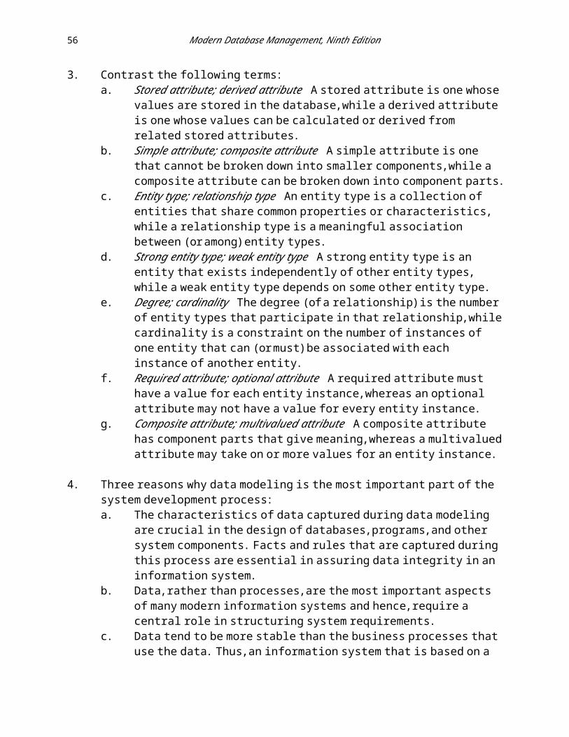
Four types of cardinality constraints are:a. Optional one:
b. Mandatory one:
c. Optional many:
d. Mandatory many:
11. PHONE CALL (see below) is an example of a weak entity because a phone call must be placed by a PERSON. Because in this simple example, PHONE CALL is related to only one other entity type, it is not necessary to show the identifying relationship; however, if this data model were ever expanded so that PHONE CALL related to other entity types, it is good practice to always indicate the identifying relationship.
56

Full file at http://testbank360.eu/solution-manual-modern-database-management-9th-edition-hoffer
12. The degree of a relationship is the number of entity types that participate in the relationship.1) Unary (one entity type):
2) Binary (two entity types):
3) Ternary (three entity types):

Modern Database Management, Ninth Edition
13. Attribute examples:a. Derived – distance (rate x time)b. Multivalued – spoken languagec. Composite – flight ID (flight number + date)
14. Examples of relationships:a. Ternary
b. Unary
58
Full file at http://testbank360.eu/solution-manual-modern-database-management-9th-edition-hoffer
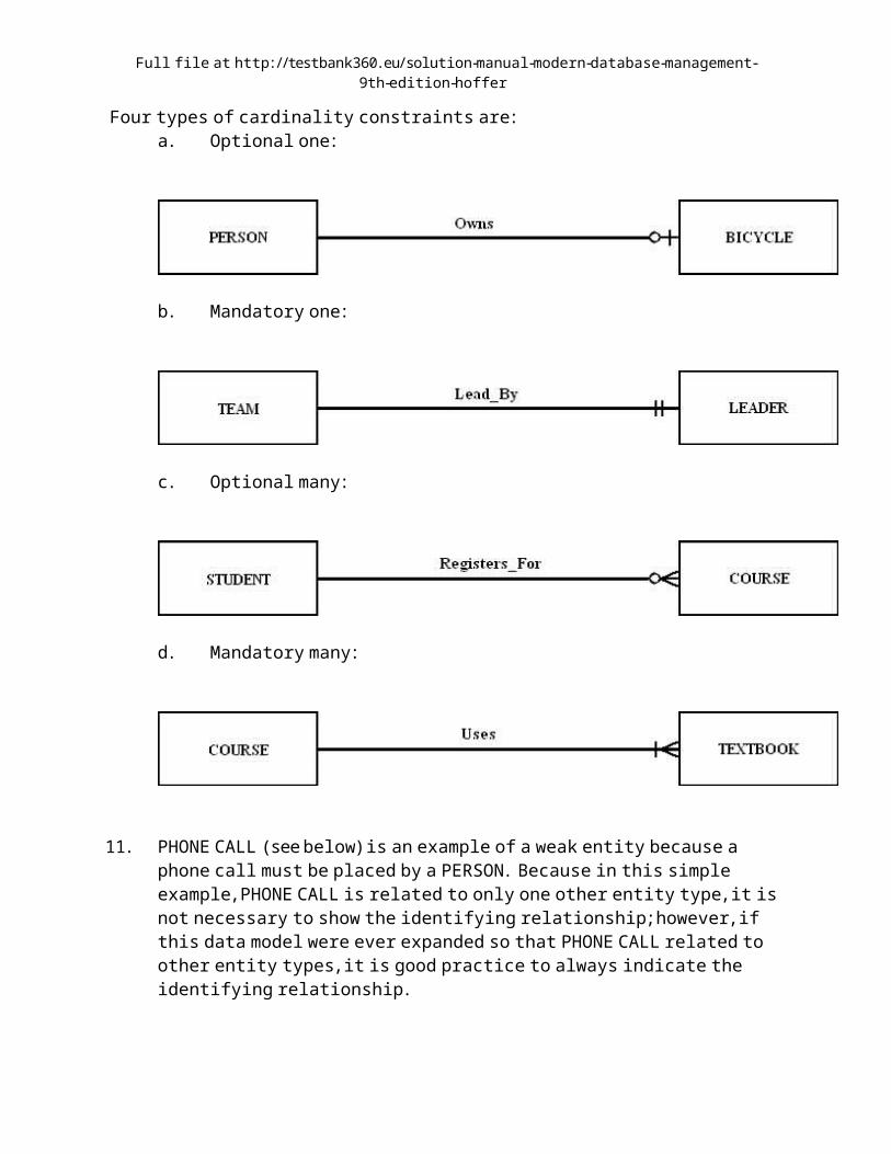
15.
16.When the attribute is the identifier or some other characteristic of an entity type in the data model, and multiple entity instances need to share these same attributes.
17. A relationship name should always be a verb phrase and should state the action taken,
as opposed to the result of the action taken. Use descriptive, powerful verb phrases as opposed to vague names.
18. The relationship definition should also explain the following: any optional participation the reason for any explicit maximum cardinality any mutually exclusive relationships any restrictions on participation in the relationship the extent of history that is kept in the relationship whether an entity instance involved in a relationship instance can transfer
participation to another relationship instance
19. Presently, the cardinality is one-to-many. One possible scenario is an employee who is supervised by more than one manager. This would make the cardinality many-to-many. Another possibility is that the employee is supervised by one manager, and the manager only supervises one employee. This would result in a one-to-one cardinality. If we take time/history into consideration, the idea of someone being managed currently versus never being managed could affect the cardinality. As we can see here, you cannot always tell what the business rule is by looking at the ERD. These possible scenarios will need to be discussed with the end user to determine the “correct” modeling representation for the business rules at this organization.
20. An entity type can be thought of as a template, defining all of the characteristics of an entity instance. For example, “student” would be an entity type, whereas you are an instance of “student.”

Modern Database Management, Ninth Edition
Answers to Problems and Exercises
1. Each answer refers to Figure 3-22 found in the chapter text.
a) Where is a unary relationship, what does it mean, and for what reasons might the cardinalities on it be different in other organizations?
A unary relationship is shown with the EMPLOYEE entity; An EMPLOYEE Supervises 0:M EMPLOYEEs, An EMPLOYEE Is_Supervised_By 0:1 EMPLOYEE. This relationship tells us that we can determine what employees are supervised by another employee, as well as determine which employees are supervisors in this company.
In other organizations, there may be different policies regarding employee supervision that could cause the data relationships among EMPLOYEE instances to be different. For instance, another company might allow an employee to have multiple supervisors (e.g., in an organization with a matrix structure).
b) Why is Includes a one-to-many relationship and why might this ever be different in some other organization?
Includes is a one-to-many (1:M) relationship because of the business rules that PVFC has in place: “a product line may group any number of products but must group at least one product; and each product must belong to exactly one product line.” Another organization may have other business rules that could permit a product being assigned to more than one product line (changing Includes to a M:M relationship). Alternatively, another organization might also show Includes as a (1:M) overall relationship but might permit the establishment of a PRODUCT_LINE without identifying PRODUCTs that belong to this group (e.g., thus permitting an optional minimum cardinality on the PRODUCT side of the Includes relationship).
c) Does Includes allow for a product to be represented in the database before it is assigned to a product line (e.g., while the product is in research and development)?
No, Figure 3-22 shows that the PRODUCT must be Included in at least 1 PRODUCT_LINE by the mandatory 1 and only 1 cardinality notation near the PRODUCT_LINE portion of the Includes relationship line. The cardinality notation would have to be changed to show optional 1 cardinality in order to represent the research and development situation.
d) Suppose there were a different customer contact person for each sales territory in which a customer did business, where in the data model would we place this person’s name?
The Does_Business_In associative entity, that associates a single instance of a SALES_TERRITORY with a single instance of a CUSTOMER, would permit the tracking of a customer contact person name for each sales territory in which a customer did business.
e) What is the meaning of the Does_Business_In associative entity and why does each Does_Business_In instance have to be associated with exactly one SALES_TERRITORY and CUSTOMER?
60

Full file at http://testbank360.eu/solution-manual-modern-database-management-9th-edition-hoffer
The Does_Business_In associative entity associates a single instance of a SALES_TERRITORY with a single instance of a CUSTOMER for the overriding M:M Does_Business_In relationship between SALES_TERRITORY and CUSTOMER. Each Does_Business_In instance must be related to exactly one SALES_TERRITORY and one CUSTOMER because the business rules of PVFC indicate that sales territories have been established for its customers. In particular, the rules are: a SALES_TERRITORY has one-to-many CUSTOMERs; and a CUSTOMER may do business in 0:M SALES_TERRITORIES. When converting this M:M relationship on the ERD, the cardinalities near the originating entities will always be mandatory 1, indicating the exactly one relationship with each entity’s instances and the associative entity’s instance.
f) In what way might Pine Valley change the way it does business that would cause the Supplies associative entity to be eliminated and the relationships around it change?
According to current business practice at PVFC, each RAW_MATERIAL is provided by 1 or more VENDORs and a VENDOR supplies 0, 1, or many RAW_MATERIALs and this is represented by the Supplies associative entity. The PVFC could consider entering into exclusive supplier arrangements with particular vendors such that an instance of RAW_MATERIAL is supplied by only 1 VENDOR. If that situation should occur, then the overall relationship between RAW_MATERIAL and VENDOR would change to 1:M (instead of M:M) and the Supply_Unit_Price attribute could become part of the RAW_MATERIAL entity instance; the Supplies associative entity would no longer need to be on the ERD.
2. Analysis of Figure 3-22:2.1. Entities PRODUCT, PRODUCT_LINE; relationship Includes2.2. Entities CUSTOMER, ORDER; relationship Submits2.3. Entities ORDER, PRODUCT; associative entity Order_Line2.4. Entities CUSTOMER, SALES_TERRITORY; associative entity Does_business_in2.5. Entities SALESPERSON, SALES_TERRITORY; relationship Serves2.6. Entities PRODUCT, RAW_MATERIAL; relationship Uses2.7. Entities RAW_MATERIAL, VENDOR; relationship Supplies2.8. Entities WORK_CENTER, PRODUCT; associative entity Produces_In2.9. Entities EMPLOYEE, WORK_CENTER; associative entity Works_In2.10. Entity EMPLOYEE; relationship Supervises, Is_supervised_by
3. Student answers will vary based on the CASE or drawing tool that is used and their personal experiences using the tool. The answers should describe their experiences with the CASE or drawing tool in terms of the requirements of the E-R notation used in the chapter. Expect to see students make reference to noting identifiers, using associative entities, using cardinality constraints properly, indicating required vs. optional attributes, and noting derived/composite/multivalued attributes.

Modern Database Management, Ninth Edition
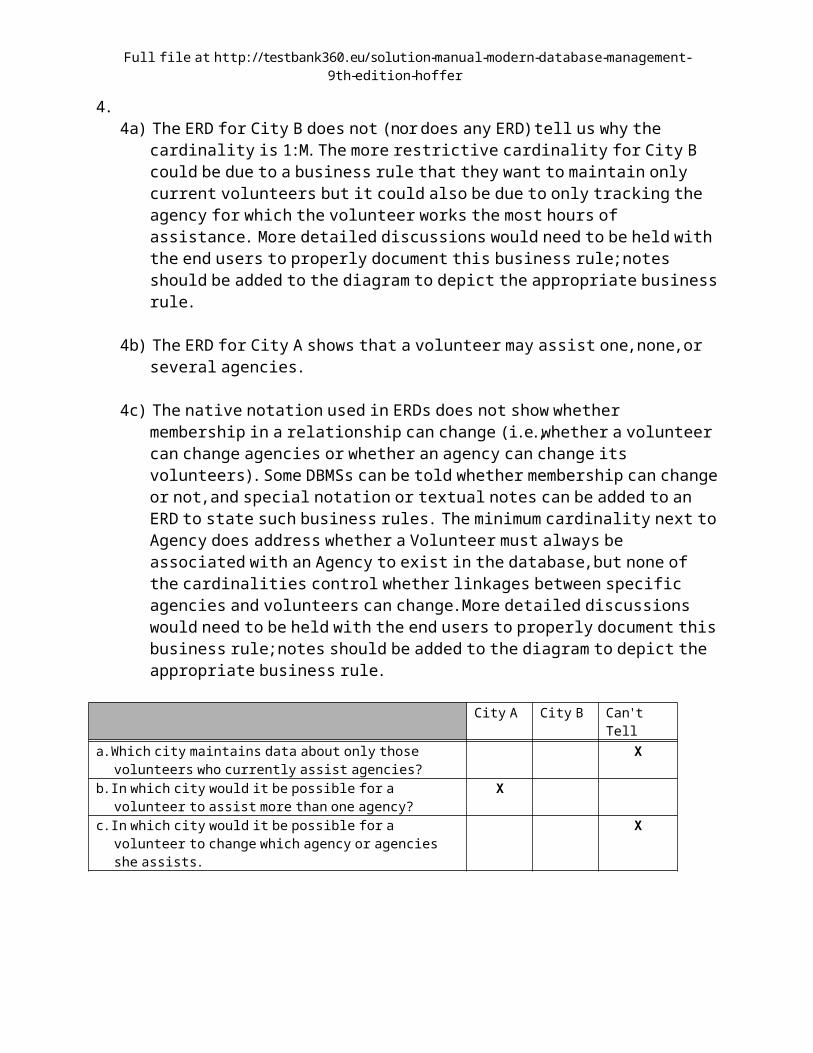
4.4a) The ERD for City B does not (nor does any ERD) tell us why the cardinality is 1:M.
The more restrictive cardinality for City B could be due to a business rule that they want to maintain only current volunteers but it could also be due to only tracking the agency for which the volunteer works the most hours of assistance. More detailed discussions would need to be held with the end users to properly document this business rule; notes should be added to the diagram to depict the appropriate business rule.
4b) The ERD for City A shows that a volunteer may assist one, none, or several agencies.
4c) The native notation used in ERDs does not show whether membership in a relationship can change (i.e., whether a volunteer can change agencies or whether an agency can change its volunteers). Some DBMSs can be told whether membership can change or not, and special notation or textual notes can be added to an ERD to state such business rules. The minimum cardinality next to Agency does address whether a Volunteer must always be associated with an Agency to exist in the database, but none of the cardinalities control whether linkages between specific agencies and volunteers can change. More detailed discussions would need to be held with the end users to properly document this business rule; notes should be added to the diagram to depict the appropriate business rule.
City A City B Can't Tella. Which city maintains data about only those volunteers who
currently assist agencies?X
b. In which city would it be possible for a volunteer to assist more than one agency?
X
c. In which city would it be possible for a volunteer to change which agency or agencies she assists.
X
62
Full file at http://testbank360.eu/solution-manual-modern-database-management-9th-edition-hoffer
5.5a.
Yes, the attribute names do generally follow the guidelines for naming attributes.
5b.
Assignment: All three entities participate in the Assigned relationship that is modeled as an associative entity Assignment, since the Assign_Date for each Chemist’s assignment to a particular project and equipment item must be tracked. However, EQUIPMENT and PROJECT do not need to participate in any assignments. All entities can have multiple assignments.

Modern Database Management, Ninth Edition
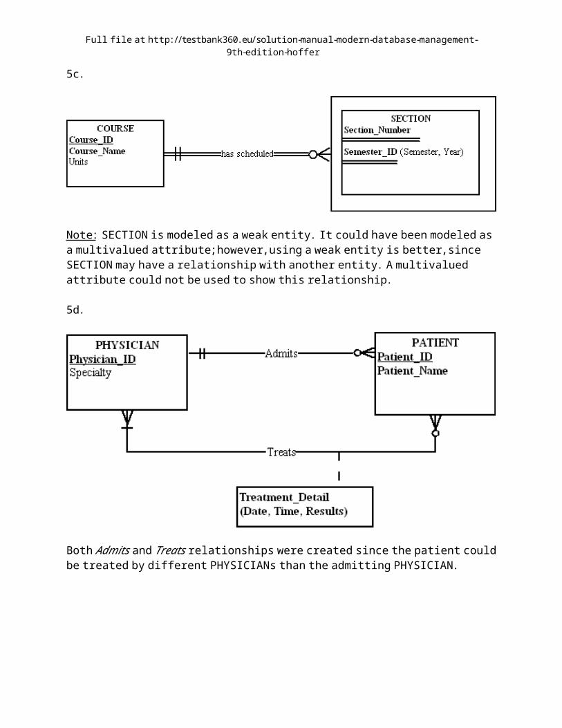
5c.
Note: SECTION is modeled as a weak entity. It could have been modeled as a multivalued attribute; however, using a weak entity is better, since SECTION may have a relationship with another entity. A multivalued attribute could not be used to show this relationship.
5d.
Both Admits and Treats relationships were created since the patient could be treated by different PHYSICIANs than the admitting PHYSICIAN.
64
Full file at http://testbank360.eu/solution-manual-modern-database-management-9th-edition-hoffer
5e. First situation: credit check can be used by more than 1 request.
Using 1 entity type seems much simpler since the credit check and rating only apply to this credit request. However, Credit_Check_Date and Credit_Rating will be blank (null) until the credit check is received.
5f. Starting point diagram:

Modern Database Management, Ninth Edition
(5f continued) Situation 1 - Adding Hourly_Rate attribute: this could be added to the CONSULTANT entity as the business rule is that a CONSULTANT Works for only 1 COMPANY at a time.
Situation 2 – Tracking a consultant’s contract. Note that CONTRACT is added as another entity that participates in a binary relationship with COMPANY and a binary relationship with CONSULTANT. We have moved Hourly_Rate to the CONTRACT entity, which permits a CONSULTANT to vary his/her Hourly_Rate as a function of the particular CONTRACT for a COMPANY. As only current CONTRACTs are tracked, an alternative solution would be to move the CONSULTANT attributes into the CONTRACT entity and eliminate the CONSULTANT entity from the model. The downside to this alternative solution is that Consultant_Name and Consultant_Specialty would occur redundantly in the CONTRACT entity instances.
Situation 3: we want to track historical CONTRACT information. We can create an associative entity for CONTRACT. I’ve also added Contract_ID as a surrogate identifier that is a unique serial number (not a composite identifier, as shown in Situation 2 above).
66
Full file at http://testbank360.eu/solution-manual-modern-database-management-9th-edition-hoffer
5g.

Modern Database Management, Ninth Edition
5h. NOTES TO INSTRUCTOR for P&E 5h: This problem and exercise is a good lead-in for Chapter 4 modeling notation for the Extended Entity Relationship Diagram (EERD). The P&E offers several chances to provide better representation in the EERD (with subtyping) than the ERD notation that is provided in Chapter 3. Using EERD notation, a single LEGAL_ENTITY can be shown as a supertype, with subtypes of DEFENDANT and PLAINTIFF. The ‘type’ (person or Organization) characteristic of both DEFENDANT and PLAINTIFF may also be considered for further subtyping. The solution presented here is a valid answer to the P&E, given the limitations of basic ERD notation and what is currently known about the situation.
This P&E also provides the instructor with an opportunity to discuss how history might be modeled if the business assumption regarding the tracking of Net_Worth for both Plaintiff and Defendant was changed from only being concerned with Net_Worth at the time of the CASE, to wanting to track the Net_Worth over time of each party to the CASE. Refer to the chapter section on “Modeling Time-Dependent Data” and Figure 3-19 for more information on how this ERD could be revised.
68
Full file at http://testbank360.eu/solution-manual-modern-database-management-9th-edition-hoffer
5i.

Modern Database Management, Ninth Edition
6. NOTE: The addition of Semester and Year attributes on the Registers_for relationship allows this diagram (and resulting database) to reflect multiple semesters of data.
7. Note: Assume Student_Name is unique and available to be used as the identifier.
70
Full file at http://testbank360.eu/solution-manual-modern-database-management-9th-edition-hoffer
8.

Modern Database Management, Ninth Edition
8. continuedEntities:
Employee: An employee of the firm. An employee works for one sales office and may manage one sales office. It is not explicitly indicated that the employee can only manage the office that he/she works for. This would require a business rule.
Sales_Office: The office where real estate is sold.
Property: Buildings for sale, such as houses, condos and apartment buildings.
Owner: The individual who owns one or more properties.
Attributes on Employee:Employee_ID: A unique identifier for an employee. This attribute must be unique.Employee_Name: The name of the employee.
Attributes on Sales_Office:Office_Number: A unique identifier for the office.Location: The physical location of the sales office. This data may be made up of the city
and state.
Attributes on Property:Property_ID: The unique identifier for the property.Location: A composite attribute that consists of the street address, city, state, and Zip
Code.
Attributes on Owner:Owner_ID: The unique identifier for the owner.Owner_Name: The name of the owner.
Relationship:Is_assigned: An employee is assigned to one sales office. A sales office may have many
employees assigned but must have at least one employee.
Manages: An employee may manage one sales office or no sales office. Each sales office is managed by one employee. A business rule is needed here in order to indicate that an employee can only manage the sales office in which he or she works.
Lists: Each property is listed by only one sales office. Each sales office can list one, none, or many properties.
Owns: Each property has one or more owners. Each owner can own one or more properties. Percent_owned is an attribute on Owns; it tracks the percent of property that the owner owns.
72

Full file at http://testbank360.eu/solution-manual-modern-database-management-9th-edition-hoffer
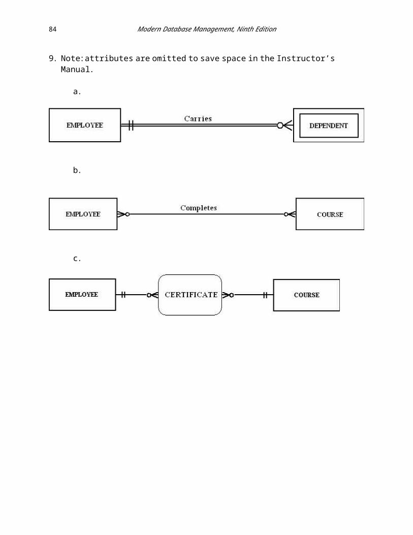
9. Note: attributes are omitted to save space in the Instructor’s Manual.
a.
b.
c.

Modern Database Management, Ninth Edition
d.
74

Full file at http://testbank360.eu/solution-manual-modern-database-management-9th-edition-hoffer
e.
f.

Modern Database Management, Ninth Edition
10.
76

Full file at http://testbank360.eu/solution-manual-modern-database-management-9th-edition-hoffer
Problem & Exercise 10e:
The solution in 10d does not place any restrictions on the number of persons to whom any one person is simultaneously married, thus the 10d solution is sufficient in representing the lack of legal restrictions regarding the number of marriage partners.

Modern Database Management, Ninth Edition
11.
78

Full file at http://testbank360.eu/solution-manual-modern-database-management-9th-edition-hoffer
12. Are associative entities also weak entities? Why or why not? If yes, is there anything special about their “weakness”?
A weak entity requires the presence of another entity type; the weak entity does not exist independently from the other entity type and has no business meaning in the ERD without the other entity type. A weak entity will not have its own identifier, but will have a partial identifier attribute that will later be combined with the identifier of its strong entity owner to create a full identifier.
An associative entity is an entity type that associates the instances of one or more entity types and contains attributes specific to the relationship between those entity instances. An associative entity generally has independent business meaning to end users and can be identified with a single-attribute identifier. If an associative entity meets these conditions, then it would not be considered a weak entity.
13. Figure 3-27 shows two diagrams (A and B), both of which are legitimate ways to represent that a stock has a history of many prices. Which of the two diagrams do you consider a better way to model this situation and why?
NOTE TO INSTRUCTOR: Student answers may vary. The crux of the answer relies upon what is the purpose of the ER diagram for the modeling situation and how end users in the organization “see” the situation. In particular, do people in the organization have a term for stock_price and refer to it as its own concept? If so, solution B may be the “better” way to model this situation. Instructors may also use solution B to demonstrate an issue related to view integration (topic in chapter 5) where transitive dependencies emerge; solution B makes the model easy to expand so that stock prices may have relationships that do not directly involve the STOCK entity.
Solution A indicates that each STOCK has multiple prices and is well-suited to early discussions with end users about the data needs of a system. Solution B adds the precision of multiple STOCK_PRICE entity instances occurring for each STOCK entity instance. Solution B indicates that STOCK_PRICE is a weak entity whose instances do not exist independently in the database without a corresponding STOCK entity instance. Solution B presents more precise detail of the data relationships that will likely be developed in the logical design of the database; this model may more closely resemble the relational model implementation of this design. Solution B also makes it easy to expand the model so that stock prices may have relationships with other entities that do not directly involve the STOCK entity.
The crux of the answer relies upon what is the purpose of the ER diagram for the modeling situation and how end users in the organization “see” the situation.

Modern Database Management, Ninth Edition
14.
A SOLOIST performs one or more COMPOSITIONs at one or more CONCERTs. This is modeled using a ternary relationship, Performs, which is shown as an associative entity PERFORMANCE.
80

Full file at http://testbank360.eu/solution-manual-modern-database-management-9th-edition-hoffer
15. Note to instructor: Student answers to this problem and exercise will vary based on their life experiences (e.g., do the students actually receive and review monthly/annual credit card statements), the drawing tool used, and the documents chosen. Three alternative solutions are presented and are ordered from the least complex to the most complex scenario. The purpose of this problem and exercise is to begin sensitizing students to the occurrence of synonyms and homonyms when ERDs are created. The actual topic does not show up until Chapter 4, but this problem and exercise can be a good lead-in for this discussion.
Alternative One: 15a

Modern Database Management, Ninth Edition
Alternative One: 15b
Alternative One: 15c
Do you find the same entities, attributes, and relationships in the two ERDs you developed for parts a and b? What differences do you find in modeling the same data entities, attributes, and relationships between the two ERDs? Can you combine the two ERDs into one ERD for which the original two are subsets? Do you encounter any issues in trying to combine the ERDs? Suggest some issues that might arise if two different data modelers had independently developed the two data models.
Yes, the same entities of CUSTOMER and ACCOUNT are in both sets of ERDs; these entities also appear to share the same attributes in each ERD. The relationship between CUSTOMER and ACCOUNT in part a ERD is Owns, while in part b ERD it is Holds. This would appear to be the same kind of relationship between entity instances in both ERDs. Also, the TRANSACTION entity in part b appears to be the same as ACTIVITY
82

Full file at http://testbank360.eu/solution-manual-modern-database-management-9th-edition-hoffer
in part a.
There appear to be differences in the level of detail that is modeled in the ACTIVITY entity with respect to the description of the activity charge when it is compared to the TRANSACTION entity’s TxnDesc attribute. Additionally, the part b ERD shows additional entities of SPENDING_SUB_CATEGORY and SPENDING_CATEGORY that are related to TRANSACTION; these additional entities are not in evidence in the part a ERD.
It would appear that these two ERDs can be combined into one ERD with minimal confusion. However, further clarification from the end user is necessary to determine the meaning (semantics) of the Activity_Type attribute in part a ERD and the Txn_Desc attribute in part b ERD. Further, some discussion is necessary to determine whether the use of “Activity” or “Transaction” terminology is preferred with the end users so proper decisions can be made about attribute naming conventions.
If two data modelers had independently modeled these user views, it is possible that even greater variance might be evidenced between the entity, attribute, and relationship names. It is also possible that the data modeler working on the Monthly Statement user view might not have been as specific in noting the composition of the Activity_Desc attribute; thus, it would not be apparent that contact information related to the Merchant is part of this data model.
Alternative One: 15dHow might you use data naming and definition standards to overcome the issues you identified in part c?
Naming and definition standards could be used to develop common Classes [e.g., Identifier (ID), Number (No), Date (Date), Address (Addr), Transaction (Txn), Description (Desc)] and Qualifiers [Post, Transaction, Activity], as well as how attribute names will be noted (i.e., Account_No vs. AccountNo).
Modern Database Management, Ninth Edition
Alternative Two: 15a
84

Full file at http://testbank360.eu/solution-manual-modern-database-management-9th-edition-hoffer
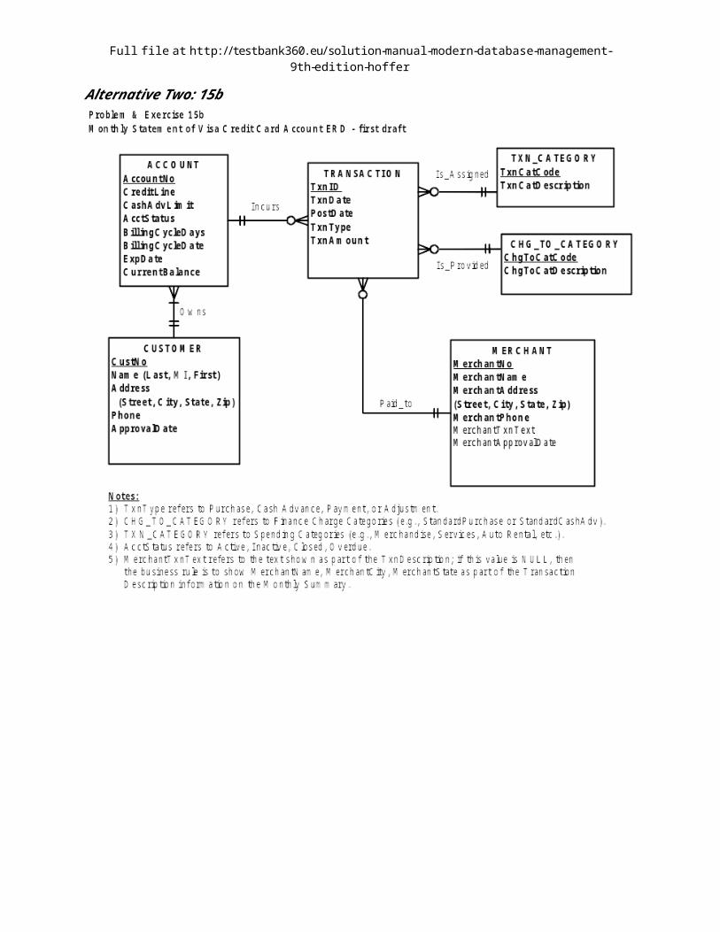
Alternative Two: 15b

Modern Database Management, Ninth Edition
Alternative Two: 15c
Do you find the same entities, attributes, and relationships in the two ERDs you developed for parts a and b? What differences do you find in modeling the same data entities, attributes, and relationships between the two ERDs? Can you combine the two ERDs into one ERD for which the original two are subsets? Do you encounter any issues in trying to combine the ERDs? Suggest some issues that might arise if two different data modelers had independently developed the two data models.
Yes, when comparing the ERDs in part a and part b, MERCHANT appears to be the same entity in both data models. Additionally, since it is known that the physical Receipt document that was used to generate the part a ERD is actually one of the transactions that is shown on the Visa Monthly Statement, there are common attributes between RECEIPT (part a) and TRANSACTION (part b), although different names have been used in the data models. Additionally, the CC_Account_No from RECEIPT (in part a) is equivalent to the AccountNo from ACCOUNT (in part b).
The two ERDs could be combined into one ERD, however, there would need to be decisions made about how the data that crosses organizational boundaries are maintained in different organization’s databases. For instance, the Receipt_No on the Merchant’s receipts for purchases at the Merchant are relevant to the Merchant’s internal accounting records and may not be of use to the Credit Card Company’s reporting to its account cardholders. Likewise, the Credit Card Company needs to track the date that a particular account transaction is posted to the account, and this level of data is most likely not of interest to the Merchant.
Aside from this larger issue, there are some minor naming issues that will need to be overcome if the data models are combined. Even though the MERCHANT entities are the same, standardization on names for the attributes needs to be resolved (e.g., Merchant_ID vs. MerchantNo; Merchant_Name vs. MerchantName, etc.). Additionally, the business usage of Transactions versus Receipt language needs to be sorted out.
If two different data modelers had developed these ERDs, there would likely be even more variance in how the names of Entities, Attributes, and Relationships would have been established. It’s also possible that the different data modelers would not recognize that the RECEIPT and TRANSACTION entities are similar, if they did not share the sample data from each separate user view with each other.
86

Full file at http://testbank360.eu/solution-manual-modern-database-management-9th-edition-hoffer
Alternative Two: 15dHow might you use data naming and definition standards to overcome the issues you identified in part c?
Naming and definition standards could be used to develop common Classes [e.g., Number (No), Credit Card (CC), Date (Date), Address (Addr), Transaction (Txn), Description (Desc)] and Qualifiers [Post, Transaction, Activity, BillingCycle], as well as how attribute names will be noted (i.e., Account_No vs. AccountNo).
Alternative Three: 15a

Modern Database Management, Ninth Edition
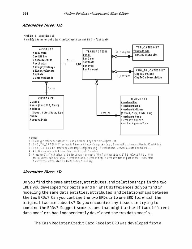
Alternative Three: 15b
Alternative Three: 15c
Do you find the same entities, attributes, and relationships in the two ERDs you developed for parts a and b? What differences do you find in modeling the same data entities, attributes, and relationships between the two ERDs? Can you combine the two ERDs into one ERD for which the original two are subsets? Do you encounter any issues in trying to combine the ERDs? Suggest some issues that might arise if two different data modelers had independently developed the two data models.
The Cash Register Credit Card Receipt ERD was developed from a user view of the Customer purchasing items from a Store, and reflects the entities and attributes present on that user view and sample data available in the actual user document. This data model will provide the Customer with a receipt including details of what was purchased, the
88

Full file at http://testbank360.eu/solution-manual-modern-database-management-9th-edition-hoffer
quantity of the item purchased, the price for each item purchased, as well as tax and the total charge to the credit card account. From the Store’s perspective, this data model provides tracking of the Cashier and Register related to the overall sales transaction, as well as credit card processing information (e.g., type of card, charge amount, card account number, and authorization code), and information related to management of the Store’s inventory (e.g., item information and quantities).
The Monthly Statement of a Visa Credit Card Account ERD was developed from a user view sent to the Account Owner of the Visa Credit Card and reflects the entities and attributes present in the data on the sample document. This data model serves both the Account Owner by providing details of all transactions posted against the Credit Card Account, and also the Visa Credit Card Company by providing transaction charges for both customers and merchants served.
When these two ERDs are reviewed, it does not appear that any entities, attributes, or relationships are named the same which seems to indicate that none of these are the same between the two ERDs. However, since both the receipt and the monthly statement are for my own purchases with a credit card, it is known that some of the data underlying both of these data models is the same, although different names have been used. For instance, the monthly statement shows a listing of individual credit card receipts. Although in this case, the individual receipt shows more detail that is shown on the monthly statement, it can be seen that the underlying data is the same. The STORE entity in part a is actually equivalent to the MERCHANT entity in part b. The CC_Charge_Amount, Date (from RECEIPT) in part a is the same as the TxnAmount, TxnDate (from TRANSACTION) in part b. Finally, the CC_Account_No (from RECEIPT) in part a is equivalent to the AccountNo (from ACCOUNT) in part b.
Although it is technically feasible to combine these two ERDs into one ERD, it would not be advisable due to the difference in the level of detail captured (e.g., Store Inventory Management data in part a) in the two models and due to the different purposes (and ultimate end users) of the data. Naming standards would also have to be developed to accomplish the merging of the data models. If two data modelers had developed these ERDs, it is unlikely that the common underlying data would have been identified.
Alternative Three: 15dHow might you use data naming and definition standards to overcome the issues you identified in part c?
Naming and definition standards could be used to develop common Classes [e.g., Number (No), Credit Card (CC), Date (Date), Address (Addr), Transaction (Txn), Description (Desc)] and Qualifiers [Post, Transaction, Activity, BillingCycle], as well as how attribute names will be noted (i.e., Account_No vs. AccountNo). However, these standards would not address the level of detail and purpose issues identified earlier as issues in merging the ERDs.
Modern Database Management, Ninth Edition
16. Projects, Inc. ERD
Notes: We assume that a Vendor will be tracked in our database even if they have not
participated in a Buys_From relationship with a department, hence, the 0:M cardinality next to Department in the diagram. This permits the tracking of a Vendor in our database prior to the first transaction with us.
We assume that we may set up a department in our company that may not yet have employees assigned to it; thus, the 0:M cardinality next to Employee on the Belongs_To relationship between Employee and Department.
Classes: Number (No), Identifier (ID), Date
Qualifiers: Married, Of_Birth, Last meeting
90
Full file at http://testbank360.eu/solution-manual-modern-database-management-9th-edition-hoffer
17. Stillwater Antiques ERD

Modern Database Management, Ninth Edition
18. H.I. Topi School of Business ERD
92

Full file at http://testbank360.eu/solution-manual-modern-database-management-9th-edition-hoffer
19. PVFC ERD

Modern Database Management, Ninth Edition
20. Emerging Electric ERD
21. STUDENT and ADVISORs ERD
94

Full file at http://testbank360.eu/solution-manual-modern-database-management-9th-edition-hoffer
22. In Figure 3-22, we have the following associative entities:
Does_business_in: between SALES_TERRITORY and CUSTOMERAlthough this entity has no attributes and no independent meaning, it is the only way that Visio can represent the M:N relationship between SALES_TERRITORY and CUSTOMER.
Order_Line: between PRODUCT and ORDERThis relationship has an attribute: Ordered_Quantity that reflects the amount of product on each line of the order by the customer. It has independent meaning on the Customer’s Order.
Uses: between PRODUCT and RAW MATERIALSThis relationship has one attribute, Goes_into_quantity. It also may have independent meaning, although there is no obvious independent identifier.
Supplies: between RAW MATERIALS and VENDORSince there is an attribute on this entity and it can have independent meaning, it might be a good candidate to convert to an associative entity.
Produced_in: between WORK CENTER and PRODUCT:Although this entity has no attributes and no independent meaning, it is the only way that Visio can represent the M:N relationship between WORK_CENTER and PRODUCT.
Works_in: between WORK CENTER and EMPLOYEEAlthough this entity has no attributes and no independent meaning, it is the only way that Visio can represent the M:N relationship between WORK_CENTER and EMPLOYEE.
Has_Skill: between EMPLOYEE and SKILLAlthough this entity has no attributes and no independent meaning, it is the only way that Visio can represent the M:N relationship between SKILL and EMPLOYEE.
There are so many associative entities because there are many M:N relationships that have independent meaning and because Visio’s templates cannot represent M:N relationships.

Modern Database Management, Ninth Edition
23. Wally’s Wonderful World of Wallcoverings ERD:
96

Full file at http://testbank360.eu/solution-manual-modern-database-management-9th-edition-hoffer
24. Peck and Paw ERD:

Modern Database Management, Ninth Edition
25.
98
26. a. The address attributes of employee, customer, and vendor do not currently contain the street, city, or state.
26b. There could be more than 1 product finish for a product, which could affect the price.
26c. Yes, this would be possible. For example, a customer could have more than 1 address.
27.
Suggestions for Field Exercises
1. The intent of this exercise is to have your students gain some exposure to standards in the business world. This is a good opportunity for your students to learn the benefits of enforcing naming standards, whether for E-R models or for programming code. If standards do not exist in the organization, have your students come up with some guidelines for naming standards. If standards do exist, your students should ask the database or systems analyst for an opportunity to review these standards to see if they are consistent and uniform.
2. You may choose to use the same organizations for this field exercise that were used in Field Exercise 4 in Chapter 1, or instead choose different organizations. It is likely that some of your students may have contacts in suitable organizations. The main difference that students are likely to find in a manufacturing company (compared to a service company)

is the complexity encountered in modeling a product structure (or bill of materials). This often results in a recursive unary relationship, which is described in this chapter.
3. This field exercise can be performed in conjunction with Exercise 2 above. Most organizations will probably have examples of each of these types of relationships. Be on the alert to discover ternary relationships that are mistakenly modeled as multiple binary relationships.
4. This field exercise can be combined with Exercise 3 above. It is quite likely the organization will be using E-R notations that are different from the text, but students should be able accommodate different notations with some explanation.
5. We suggest you combine this with Exercise 4 (and perhaps Exercise 3) above. If time-dependent data is apparent in the models, you might ask, for example, how the organization tracks customer sales over time.
6. Students should build a table to compare features of all products.
Project Case
Case Questions
1. Mountain View Community Hospital (MVCH) would want to use ER modeling to understand its data requirements because this approach will provide a pictorial depiction of MVCH’s business rules about data and how it is managed in the organization. The ER model provides a representation of these rules so they can be unambiguously understood by system developers and end users. The hospital might also want to model their requirements using the object-oriented model (see later chapter in text). Other possible diagrams might be data flow diagrams (DFD), state-transition diagrams, or use case diagrams.
2. No; Mountain View Community Hospital is an instance of the entity type HOSPITAL. Since there is only one instance, there is no need to model the HOSPITAL entity type.
3.a. BED may be a weak entity because it appears to require a Care_Center_ID attribute
(per case description). MVCH may have a business rule requiring a BED to be assigned to a CARE_CENTER in order for the system to track the BED.
b. There are no multivalued attributes.
c. Between PATIENT and PHYSICIAN there are two relationships: refers and admits. Between EMPLOYEE and CARE_CENTER there are two relationships: has_assigned and nurse_in_charge.
4. At this stage in our understanding of E-R diagrams, we simply diagram the relationship (called Is_assigned) between PATIENT and BED as an optional 0-1 relationship. In

Chapter 4 we will learn how to model the subtypes of PATIENT (IN PATIENT and OUT PATIENT) and then create a mandatory relationship between IN PATIENT and BED.
5. The only reason to split ITEM into two separate entities would be to track the use of reusable items. In other words, once an item is purchased and can be reused, one might want to see how frequently an item is used. In this case, one might wish to record the item serial number (or assign a number) and then see specifically how that item was used. However, I still think that it would be of merit to track reusable items in the general sense. For example, you might want to know that you have 100 forceps in stock. If one gets damaged and is thrown away, the inventory is reduced. Once the inventory reaches a certain level, more forceps can be ordered.
6. I would take a look at all user views by examining reports and screens from any existing systems. I would then compare these to the data model and make a determination of whether this data model will support the system’s generation of reports and screens.
Case Exercises
1. Some other questions we might like to ask are the following:a. Should we model pharmaceutical items separately from ITEM since such items
are prescribed by a physician for a patient?b. Is there a need to maintain a historical record of a patient’s relationship with the
hospital? If so, how can this be modeled in the E-R diagram?c. Need we model the various subtypes of EMPLOYEE (nurses, staff, physicians,
etc.)?d. Is there a need to model the relationship with other persons such as volunteers
and donors?You should ask your students to develop additional questions.
2.
3. No. The entity type ITEM has a Unit-Cost attribute, but has no provision to represent a unit cost per day, which would be required for items such as in-room TVs.

4.

5.

6. Yes. Any combination of patient and treatment has multiple physicians who perform that treatment.
7. Yes. The model records the date, time, and results for each treatment occurrence performed by a physician on behalf of a patient.

Project AssignmentsP1.

P2. A FACILITY can contain one or more CARE_CENTERS or may contain no CARE_CENTERS. A CARE_CENTER is part of one and only one FACILiTY.
A FACILITY may maintain one or more DIAGNOSTIC UNITS or may maintain no DIAGNOSTICUNITS. A DIAGNOSTIC UNIT is part of only one FACILITY.
A CARE_CENTER has many EMPLOYEES. Each CARE_CENTER has one EMPLOYEE assigned as a nurse_in_charge. Each EMPLOYEE may work for one or more CARE_CENTERS.
A CARE_CENTER will contain one or more ROOMs. Each ROOM is contained in only one CARE_CENTER.
A ROOM may contain one or more beds or may contain no BEDS, A BED is contained in onlyone ROOM.
A DIAGNOSTIC_UNIT performs one or more TREATMENTS. A TREATMENT is performed byonly one DIAGNOSTIC UNIT.
A BED is assigned to one patient or no patients. A PATIENT is assigned to one BED or no BEDS.
A PHYSICIAN admits one or more PATIENTS or admits no PATIENTS. A PATIENT is admitted byonly one PHYSICIAN.
A PHYSICIAN may refer one or more PATIENTS or may refer no PATIENTS. A PATIENT must be referred by one PHYSICIAN.
A PATIENT may consume many ITEMS or may consume no ITEMS. An ITEM is consumed by one or more PATIENTS or may be consumed by no PATIENTS.
An ITEM is supplied by one or more VENDORS. A VENDOR may supply one or more items ormay supply no ITEMS.
A PHYSICIAN may write one or more ORDERS or may write no ORDERS for one PATIENT. An ORDER is written by one PHYSICIAN.
An ORDER may consist of one or more ITEMS or no ITEMS. An ITEM may be part of one or moreORDERS or may be part of no ORDERS.
An ORDER may consist of one or more TREATMENTS or no TREATMENTS. A TREATMENT may be
part of one or more ORDERS.
A PHYSICIAN may complete one or more DIAGNOSES for one or more PATIENTS. A DIAGNOSIS is completed for one PATIENT by one PHYSICIAN.
A VENDOR may supply one or more ITEMs. Each ITEM may be supplied by more than one VENDOR.
An EMPLOYEE completes one, none, or many ASSESSMENTs of a PATIENT. Each PATIENT may have one or many ASSESSMENTs over time at this hospital.
A FACILITY may prepare multiple staffing schedules for its PHYSICIANs. Each SCHEDULE instance is for a single FACILITY and a single PHYSICIAN. A PHYSICIAN may have zero, one, or many SCHEDULEs.

P3. [Sample questions are listed below; student answers may vary]
a. How is patient billing done?b. What reporting requirements does the administration have?c. Should there be a distinction between a diagnostic test, a procedure, and a treatment?d. Can a physician choose which diagnostic unit to use for a test?e. How will we handle referrals by physicians who are not on staff?f. How will medical records be modeled? g. Should the relationship between patient and bed contain a start and end date?