Embed Size (px)
Citation preview

ME 101: Engineering Mechanics
Rajib Kumar Bhattacharjya
Department of Civil Engineering
Indian Institute of Technology Guwahati
M Block : Room No 005 : Tel: 2428
www.iitg.ernet.in/rkbc

A structure is called a Frame or Machine
if at least one of its individual members
is a multi-force member
• member with 3 or more forces acting, or
• member with 2 or more forces and
1 or more couple acting
Frames: generally stationary and are used to support loads
Machines: contain moving parts and are designed to transmit and alter the
effect of forces acting
Multi-force members: the forces in these members in general will not be
along the directions of the members
� methods used in simple truss analysis cannot be used
Frames and Machines

Frames and Machines
Interconnected Rigid Bodies with Multi-force Members
• Rigid Non-collapsible
–structure constitutes a rigid unit by itself
when removed from its supports
–first find all forces external to the structure treated as a single rigid body
–then dismember the structure & consider equilibrium of each part
•Non-rigid Collapsible
–structure is not a rigid unit by itself but depends on its external supports for rigidity
–calculation of external support reactions
cannot be completed until the structure is
dismembered and individual parts are
analysed.

Frames and Machines
Free Body Diagrams: Forces of Interactions• force components must be consistently represented in opposite directions on the
separate FBDs (Ex: Pin at A).
• apply action-and-reaction principle (Ex: Ball & Socket at A).
• Vector notation: use plus sign for an action and a minus sign for the corresponding
reaction
Pin Connection at A Ball & Socket at A

Frames and Machines
Example: Free Body DiagramsDraw FBD of
(a) Each member
(b) Pin at B, and
(c) Whole system

Example
Members ACE and BCD are
connected by a pin at C and by the
link DE. For the loading shown,
determine the force in link DE and the
components of the force exerted at C
on member BCD.
SOLUTION:
• Create a free-body diagram for the
complete frame and solve for the support
reactions.
• Define a free-body diagram for member
BCD. The force exerted by the link DE
has a known line of action but unknown
magnitude. It is determined by summing
moments about C.
• With the force on the link DE known, the
sum of forces in the x and y directions
may be used to find the force
components at C.
• With member ACE as a free-body,
check the solution by summing
moments about A.

Example
SOLUTION:
• Create a free-body diagram for the complete frame
and solve for the support reactions.
N 4800 −==∑ yy AF ↑= N 480yA
( )( ) ( )mm 160mm 100N 4800 BM A +−==∑
→= N 300B
xx ABF +==∑ 0 ←−= N 300xA
°== − 07.28tan150801α
Note:

Example
• Define a free-body diagram for member
BCD. The force exerted by the link DE has a
known line of action but unknown
magnitude. It is determined by summing
moments about C.
( )( ) ( )( ) ( )( )N 561
mm 100N 480mm 06N 300mm 250sin0
−=
++==∑
DE
DEC
F
FM α
CFDE N 561=
• Sum of forces in the x and y directions may be used to find the force
components at C.
( ) N 300cosN 561 0
N 300cos0
+−−=
+−==∑α
α
x
DExx
C
FCF
N 795−=xC
( ) N 480sinN 5610
N 480sin0
−−−=
−−==∑
α
α
y
DEyy
C
FCF
N 216=yC

Example
• With member ACE as a free-body, check
the solution by summing moments about A.
( )( ) ( )( ) ( )( )( ) ( )( ) ( )( ) 0mm 220795mm 100sin561mm 300cos561
mm 220mm 100sinmm 300cos
=−−−+−=
−+=∑αα
αα xDEDEA CFFM
(checks)

Frames and Machines
Example: Compute the horizontal and vertical components of all forces acting on each of the
members (neglect self weight)

Frames and Machines
Example Solution:
3 supporting members form a
rigid non-collapsible assembly
Frame Statically Determinate Externally
Draw FBD of the entire frame
3 Equilibrium equations are available
Pay attention to sense of Reactions
Reactions can be found out

Frames and Machines
Example Solution: Dismember the frame
and draw separate FBDs of each member
- show loads and reactions on each member
due to connecting members (interaction forces)
Begin with FBD of Pulley
Ax=4.32 kN
Ay=3.92 kN D=4.32 kN
Then draw FBD of Members BF, CE, and AD

Frames and Machines
Example Solution:
FBDs
Ax=4.32 kN
Ay=3.92 kN D=4.32 kN
CE is a two-force member
Direction of the line joining the two points of force application determines the direction
of the forces acting on a two-force member.Shape of the member is not important.

Frames and Machines
Example Solution:
Find unknown forces from equilibrium
Member BF
Member CE
[∑Fx = 0] Cx = Ex = 13.08 kN
Checks:

Frames and Machines
Example: Find the tension in the cables and the force P required to support the 600 N force using the frictionless pulley system (neglect self weight)
Solution:
Draw the FBD

Frames and Machines
Example Solution:
Draw FBD and apply
equilibrium equations

Frames and Machines
Example: Pliers: Given the magnitude of P, determine the magnitude of Q
Taking moment about pin AQ=Pa/b
Also pin reaction Ax=0
Ay=P(1+a/b) OR Ay=P+Q
FBD of individual parts
FBD of Whole Pliers

Example
Q. Neglect the weight of the frame and
compute the forces acting on all of its members.
Step 1: Draw the FBD and calculate the
reactions.
Is it a rigid frame?
The frame is not rigid, hence all the reaction can not the determined using the equilibrium
equations.
Calculate the reactions which are possible to calculate using the equilibrium equations

Example
Frames and Machines
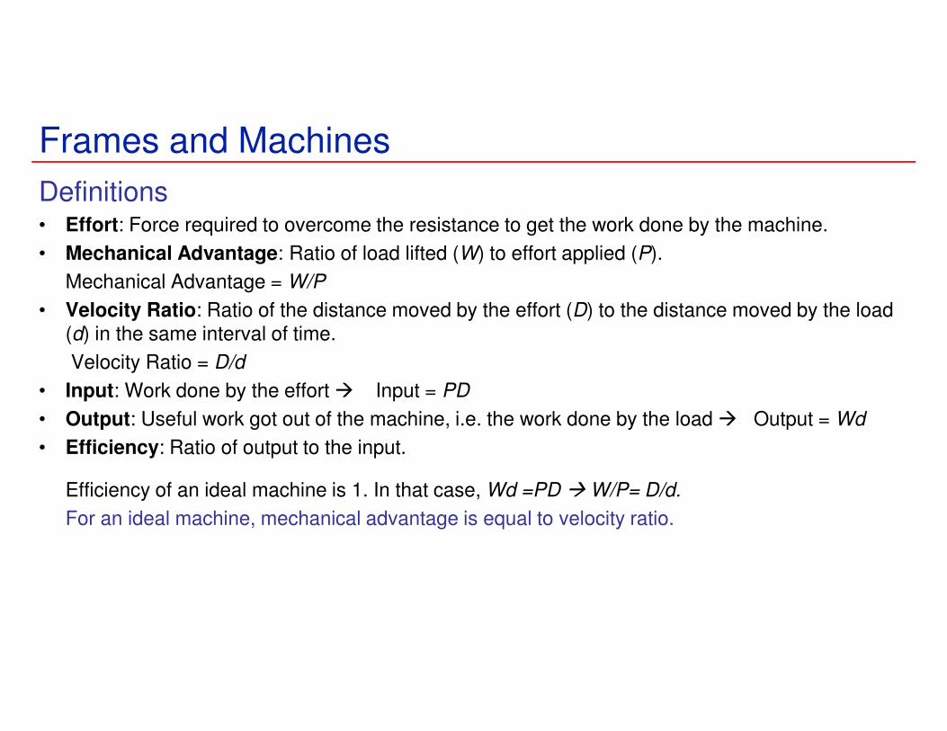
Definitions• Effort: Force required to overcome the resistance to get the work done by the machine.
• Mechanical Advantage: Ratio of load lifted (W) to effort applied (P).
Mechanical Advantage = W/P
• Velocity Ratio: Ratio of the distance moved by the effort (D) to the distance moved by the load (d) in the same interval of time.
Velocity Ratio = D/d
• Input: Work done by the effort � Input = PD
• Output: Useful work got out of the machine, i.e. the work done by the load � Output = Wd
• Efficiency: Ratio of output to the input.
Efficiency of an ideal machine is 1. In that case, Wd =PD � W/P= D/d.
For an ideal machine, mechanical advantage is equal to velocity ratio.

Frames and Machines: Pulley System
Effort = Load
� Mechanical Advantage = 1
Distance moved by effort is
equal to the distance moved
by the load.
� Velocity Ratio = 1
Effort Load
Fixed Pulley
Effort = Load/2
�Mechanical Advantage = 2
Distance moved by effort is
twice the distance moved by
the load (both rope should also
accommodate the same
displacement by which the
load is moved).
� Velocity Ratio = 2
Effort
Load
Movable Pulley
Compound Pulley
Load
Effort
MA = 4
VR = 4
MA = 3
VR = 3
www.Petervaldivia.com

Frames and Machines: Pulley System
Effort required is 1/16th of the load.
Mechanical Advantage = 16.
(neglecting frictional forces).
Velocity ratio is 16, which means in order to raise a load to 1 unit height; effort has to
be moved by a distance of 16 units.
Compound Pulley
W/2W/2
W/4
W/4
W/8W/8
W/16
W/16
W/16
Effort
Load
http://etc.usf.edu/

Beams
Beams are structural members that offer resistance to
bending due to applied load

BeamsBeams
• mostly long prismatic bars
– Prismatic: many sided, same section throughout
• non-prismatic beams are also useful
• cross-section of beams much smaller than beam length
• loads usually applied normal to the axis of the bar
• Determination of Load Carrying Capacity of Beams
• Statically Determinate Beams
– Beams supported such that their external support reactions can be calculated by the methods of statics
• Statically Indeterminate Beams
– Beams having more supports than needed to provide equilibrium

Types of Beams- Based on support conditions
Propped
Cantilever

Types of Beams- Based on type of external loading
Beams supporting Concentrated Loads
Beams supporting Distributed Loads
- Intensity of distributed load = w
- w is expressed as
force per unit length of beam (N/m)
- intensity of loading may be constant or variable, continuous
or discontinuous
- discontinuity in intensity at D (abrupt change)
- At C, intensity is not discontinuous, but rate of change of intensity (dw/dx) is discontinuous

BeamsDistributed Loads on beams
• Determination of Resultant Force (R) on beam is important
R = area formed by w and length L
over which the load is distributed
R passes through centroid of this area
?

BeamsDistributed Loads on beams
• General Load Distribution
Differential increment of force is
dR = w dx
Total load R is sum of all the differential forces
acting at centroid of the area under consideration
Once R is known reactions can be found out from Statics
∫= dxwR
R
dxxwx
∫=

Beams: Example
Determine the external reactions for the beam
RA = 6.96 kN, RB = 9.84 kN

∑Fx=0 � Ax = 1.5sin30 = 0.75 kN
∑MA=0 �
4.8xBy = 1.5cos30x3.6 + 1.2x1.0 By = 1.224 kN
∑Fy=0 �
Ay = 1.8+1.2+1.5cos30-1.224Ay = 3.075 kN
Beams: Example
Determine the external reactions for the beam
Dividing the un-symmetric
triangular load into two parts with resultants R1 and R2 acting
at point A and 1m away from point A, respectively.
R1 = 0.5x1.8x2 = 1.8 kN
R2 = 0.5x1.2x2 = 1.2 kN
Ay
Ax
By
R1 R2
0.4m

Beams: Example
Determine the external reactions for the beam
60 kN/m
24 kN/m
Ay
MA
R136 kN/m
R2
Dividing the trapezoidal load into two
parts with resultants R1 and R2
R1 = 24x2.5 = 60 kN @ 3.75m � AR2 = 0.5x2.5x36=45 [email protected] � A
(distances from A)
∑MA=0 �
MA-40+50x4.0-60x3.75-45x4.17=0 MA = 253 kNm
∑Fy=0 �
Ay -50+60+45 = 0Ay = -55 kN ���� Downwards

Beams – Internal Effects
• Internal Force Resultants
• Axial Force (N), Shear Force (V), Bending Moment (M), Torsional Moment (T) in Beam
– Method of Sections is used
Axial

Beams – Internal Effects• Method of Section:
Internal Force Resultants at B � Section a-a at B and use
equilibrium equations in both cut parts

Beams – Internal Effects
• 2D Beam
• 3D Beam
The Force Resultants act at
centroid of the section’s Cross-sectional area

Beams – Internal Effects
Sign Convention
Positive Axial Force creates Tension
Positive shear force will cause the
Beam segment on which it acts to rotate clockwise
Positive bending moment will tend to
bend the segment on which it acts in a concave upward manner
(compression on top of section).

Beams – Internal Effects
Sign convention in a single plane
H-section Beam bent by two equal
and opposite positive moments applied at ends
Neglecting resistance offered by web
Compression at top; Tension at
bottom
Resultant of these two forces (one tensile and other compressive) acting on any
section is a Couple and has the value of the Bending Moment acting on the section.
Interpretation of Bending Couple

Beams – Internal EffectsExample: Find the axial force in the fixed bar at points B and C
Solution: Draw the FBD of the entire bar
Draw sections at B and C to get AF in the bar at B and C
Alternatively, take a section at C and consider only CD portion of the bar
Then take a section at B and consider only BD portion of the bar � no need to calculate reactions

Beams – Internal EffectsExample: Find the internal torques at points B and C of the circular shaft subjected to three concentrated torques
Solution: FBD of entire shaft
Sections at B and C and FBDs of shaft segments AB and CD

Beams – Internal EffectsExample: Find the AF, SF, and BM at point B (just to the left of 6 kN) and at point C (just to the right of 6 kN)
Solution: Draw FBD of entire beam
Dy need not be determined if only
left part of the beam is analysed

Beams – Internal EffectsExample Solution: Draw FBD of segments AB and AC
and use equilibrium equations

Beams – SFD and BMD
Shear Force Diagram and bending Moment Diagram
• Variation of SF and BM over the length of the beam � SFD and BMD
• Maximum magnitude of BM and SF and their locations is prime consideration in beam design
• SFDs and BMDs are plotted using method of section
– Equilibrium of FBD of entire Beam
� External Reactions
– Equilibrium of a cut part of beam
� Expressions for SF and BM at the cut section
Use the positive sign convention consistently
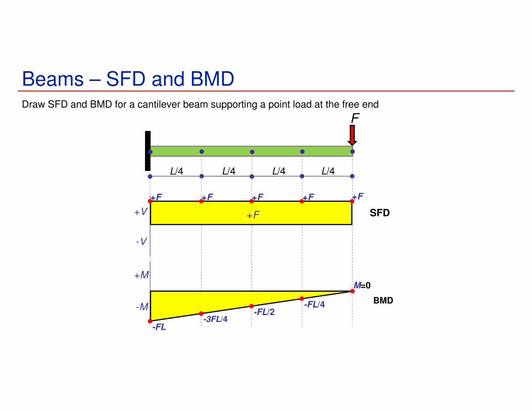
Beams – SFD and BMDDraw SFD and BMD for a cantilever beam supporting a point load at the free end
F
L/4 L/4 L/4 L/4
+V
-V
+M
-M
+F SFD
+F+F+F+F+F
BMD
-FL-3FL/4
-FL/2-FL/4
M=0

Relations Among Load, Shear, and Bending Moment • Relations between load and shear:
( )
wx
V
dx
dV
xwVVV
x−=
∆
∆=
=∆−∆+−
→∆ 0lim
0
( )curve loadunder area−=−=− ∫D
C
x
x
CD dxwVV
• Relations between shear and bending moment:
( )
( ) VxwVx
M
dx
dM
xxwxVMMM
xx=∆−=
∆
∆=
=∆
∆+∆−−∆+
→∆→∆ 21
00limlim
02
( )curveshear under area==− ∫D
C
x
x
CD dxVMM
dx
dMV =
dx
dVw −=

Beams – SFD and BMD
Shear and Moment Relationships
Slope of the shear diagram = - Value of applied loading
Slope of the moment curve = Shear Force
Both equations not applicable at the point of loading because of discontinuity
produced by the abrupt change in shear.
dx
dVw −=
dx
dMV =

Beams – SFD and BMD
Shear and Moment Relationships
Expressing V in terms of w by integrating
OR
V0 is the shear force at x0 and V is the shear force at x
Expressing M in terms of V by integrating
OR
M0 is the BM at x0 and M is the BM at x
V = V0 + (the negative of the area under
the loading curve from x0 to x)∫∫ −=x
x
V
VwdxdV00
dx
dVw −=
dx
dMV =
∫∫ =x
x
M
MVdxdM00
M = M0 + (area under the shear diagram
from x0 to x)

Beams – SFD and BMD
Degree of V in x is one higher than that of w
Degree of M in x is one higher than that of V
�Degree of M in x is two higher than that of w
Combining the two equations �
� If w is a known function of x, BM can be obtained by integrating this equation
twice with proper limits of integration.
�Method is usable only if w is a continuous function of x (other cases not part of this course)
dx
dVw −=
dx
dMV =
wdx
Md−=
2
2

Beams – SFD and BMD: Example
• Draw the SFD and BMD.
• Determine reactions at
supports.
• Cut beam at C and consider
member AC,
22 PxMPV +=+=
• Cut beam at E and consider
member EB,
( ) 22 xLPMPV −+=−=
• For a beam subjected to
concentrated loads, shear is constant between loading points
and moment varies linearly.
Maximum BM occurs where Shear changes the
direction

Beams – SFD and BMD: ExampleDraw the shear and bending moment diagrams for the beam and loading shown.
Solution: Draw FBD and find out the support reactions using equilibrium equations

Beams – SFD and BMD: Example
∑ = :0yF 0kN20 1 =−− V kN201 −=V
:01 =∑M ( )( ) 0m0kN20 1 =+ M 01 =M
Use equilibrium conditions at all sections to
get the unknown SF and BM
V2 = -20 kN; M2 = -20x kNm
V3 = +26 kN; M3 = -20x+46×0 = -20x � MB= -50 kNm
V4 = +26 kN; M4 = -20x+46×(x-2.5) � MC= +28 kNm
V5 = -14 kN; M5 = -20x+46×(x-2.5)-40×0 � MC= +28 kNm
V6 = -14 kN; M6 = -20x+46×(x-2.5)-40×(x-5.5)
� MD= 0 kNm
Alternatively, from RHS
V5 = V6 = -14 kN
M5 = +14x � MC= +28 kNm
M6 = +14×0 � MD= 0 kNm
Important: BM≠0 at Hinged
Support B. Why?

Beams – SFD and BMD: ExampleDraw the SFD and BMD for the beam
Solution:
Draw FBD of the entire beam
and calculate support reactions
using equilibrium equations
Reactions at supports:2
wLRR BA ==
w
Develop the relations between loading, shear force, and bending
moment and plot the SFD and BMD

Beams – SFD and BMD: Example
Shear Force at any section:
−=−=−=
−=−=− ∫
xL
wwxwL
wxVV
wxdxwVV
A
x
A
22
0
BM at any section:
( )2
0
0
22xxL
wdxx
LwM
VdxMM
x
x
A
−=
−=
=−
∫
∫
w
−=−= x
Lwwx
wLV
22
Alternatively,
( )2
222xxL
wxwxx
wLM −=−=
Alternatively,
=== 0at
8
2
max Vdx
dMM
wLM Q

Beams – SFD and BMD: ExampleDraw the SFD and BMD for the Beam
Solution:
SFD and BMD can be plotted without
determining support reactions since
it is a cantilever beam.
However, values of SF and BM can be
verified at the support if support
reactions are known.
( )aLawa
Law
Maw
R CC −=
−=↑= 3
632;
2
000
M
Area under SFD

Beams – SFD and BMD: Summary
2.5 m 3 m 2m
l/2 l/2
2 m 2 m
w
L
SFD
BMD
SFD
BMD

Cables
Flexible and Inextensible Cables
L12
Important
Design Parameters
Tension
SpanSag
Length

Cables
• Relations involving Tension, Span, Sag, and Length are reqd
– Obtained by examining the cable as a body in equilibrium
• It is assumed that any resistance offered to bending is negligible � Force in
cable is always along the direction of the cable.
• Flexible cables may be subjected to concentrated loads or distributed loads

Cables
• In some cases, weight of the cable is
negligible compared with the loads it
supports.
• In other cases, weight of the cable may
be significant or may be the only load
acting � weight cannot be neglected.
Three primary cases of analysis: Cables subjected to
1. concentrated load, 2. distributed load, 3. self weight
�Requirements for equilibrium are formulated in identical way
provided Loading is coplanar with the cable

Cables
Primary Assumption in Analysis:
The cable is perfectly Flexible and Inextensible
Flexible
� cable offers no resistance to bending
� tensile force acting in the cable is always tangent to the cable at points along
its length
Inextensible
� cable has a constant length both before and after the load is applied
� once the load is applied, geometry of the cable remains fixed
� cable or a segment of it can be treated as a rigid body

Cables With Concentrated Loads
• Cables are applied as structural elements
in suspension bridges, transmission lines,
aerial tramways, guy wires for high
towers, etc.
• For analysis, assume:
a) concentrated vertical loads on given
vertical lines,
b) weight of cable is negligible,
c) cable is flexible, i.e., resistance to
bending is small,
d) portions of cable between successive
loads may be treated as two force
members
• Wish to determine shape of cable, i.e.,
vertical distance from support A to each
load point.

Cables With Concentrated Loads
• Consider entire cable as free-body. Slopes of
cable at A and B are not known - two reaction
components required at each support.
• Four unknowns are involved and three
equations of equilibrium are not sufficient to
determine the reactions.
• For other points on cable,
2 yields02
yMC =∑
yxyx TTFF , yield 0,0 == ∑∑
• constantcos === xx ATT θ
• Additional equation is obtained by
considering equilibrium of portion of cable
AD and assuming that coordinates of point D
on the cable are known. The additional
equation is .0∑ =DM

Example
The cable AE supports three vertical
loads from the points indicated. If
point C is 1.5 m below the left
support, determine (a) the elevation
of points B and D, and (b) the
maximum slope and maximum
tension in the cable.
SOLUTION:
• Determine reaction force components at
A from solution of two equations formed
from taking entire cable as free-body
and summing moments about E, and
from taking cable portion ABC as a free-
body and summing moments about C.
• Calculate elevation of B by considering
AB as a free-body and summing
moments B. Similarly, calculate
elevation of D using ABCD as a free-
body.
• Evaluate maximum slope and
maximum tension which occur in DE.

Example
SOLUTION:
• Determine two reaction force components at A
from solution of two equations formed from
taking entire cable as a free-body and summing
moments about E,
( ) ( ) ( )0990186
0205.46093012186
:0
=+−
=+++−
=∑
yx
yx
E
AA
AA
M
and from taking cable portion ABC as a
free-body and summing moments about C.
( ) 030395.1
:0
=+−−
=∑yx
C
AA
M
Solving simultaneously,
kN 25kN 90 +=−= yx AA

Example
• Calculate elevation of B by considering AB as
a free-body and summing moments B.
( ) ( ) 062590:0 =−=∑ BB yM
m 67.1−=By
Similarly, calculate elevation of D using
ABCD as a free-body.
( ) ( ) ( ) ( ) 0605.4305.7255.1390
:0
=++−−
=∑Dy
M
m75.1=Dy

Example
• Evaluate maximum slope and
maximum tension which occur in DE.
5.4
25.4tan =θ °= 4.43θ
θcos
kN 90max =T kN 9.123max =T

Cables With Distributed Loads
• For cable carrying a distributed load:
a) cable hangs in shape of a curve
b) internal force is a tension force directed along
tangent to curve.
• Consider free-body for portion of cable extending
from lowest point C to given point D. Forces are
horizontal force T0
at C and tangential force T at D.
• From force triangle:
0
220
0
tan
sincos
T
WWTT
WTTT
=+=
==
θ
θθ
• Horizontal component of T is uniform over cable.
• Vertical component of T is equal to magnitude of W
measured from lowest point.
• Tension is minimum at lowest point and maximum
at A and B.

Parabolic Cable
• Consider a cable supporting a uniform, horizontally
distributed load, e.g., support cables for a
suspension bridge.
• With loading on cable from lowest point C to a
point D given by internal tension force
magnitude and direction are
,wxW =
0
2220 tan
T
wxxwTT =+= θ
• Summing moments about D,
02
:0 0 =−=∑ yTx
wxM D
0
2
2T
wxy =
or
The cable forms a parabolic curve.

Beams – SFD and BMD: ExampleDraw the SFD and BMD for the beam
acted upon by a clockwise couple at
mid point
Solution: Draw FBD of the beam and
Calculate the support reactions
Draw the SFD and the BMD starting
From any one end
Cl
C
l
C
V
l
C−
M
2
C−
2
C

Beams – SFD and BMD: ExampleDraw the SFD and BMD for the beam
Solution: Draw FBD of the beam and
Calculate the support reactions
Draw the SFD and the BMD starting
from any one end
∑MA = 0 � RA = 60 N
∑MB = 0 � RB = 60 N
120 Nm60 N
60 NV
-60 N
M
-120 Nm