Embed Size (px)
Citation preview

ME 328.3 M4‐M7 Solution 2015
THE LAB REPORT IS TO INCLUDE THE FOLLOWING TASKS IN SEQUENCE:
1. Band Saw & Chucking for CNC Lathe: Given:
Bar Stock Diameter = 52 mm
Material = 6061‐T6
Bar stock length = 20 feet
Bar stock cost = $335.28 per bar
Bar stock density = 2.70 g/cm3
a) Find the set‐up time (tr) and total cutting time (te)
Table 7, ME 328 Lab Manual:
tr = 5 min
te = 0.75 min
b) How many workpieces can we machine out of one bar?
How much is required per piece?
56 47.3 25 70 2 5110.7 → 111
Number per bar = ?
# 20111
54.92 → 54 .
c) How many bars, and how many cuts do we need to rough cut all workpieces?
# 900054
166.67 → 167
# 9000 1
d) What is the remaining length of each barstock after the last workpiece is cut?
For bars 1‐166 there is the same length left: (NOTE: 20 feet = 6096 mm)
20 111 ∗ 54 102

For the final bar:
20 111 ∗ 36 2100 .
e) Calculate the material cost. Keep in mind that the barstock is only available in 20 foot lengths.
167 ∗ $335.28 $55,991.76
f) Determine the chucking time (ttb) for the CNC lathe for each workpiece.
From table 9 of the ME 328 lab Manual, the chucking time depends on the mass of the bar stock:
∗ ∗4
2.70 ∗52
4∗ 106 607.8 0.6078
ttb = 0.3 min
2. Create a CNC‐set‐up sheet, which can be downloaded from the ME328 WEB site, showing all necessary information to set up the Baxter Entrepreneur CNC lathe (refer to the lab manual for working range details).
ZW=56.0
barstock
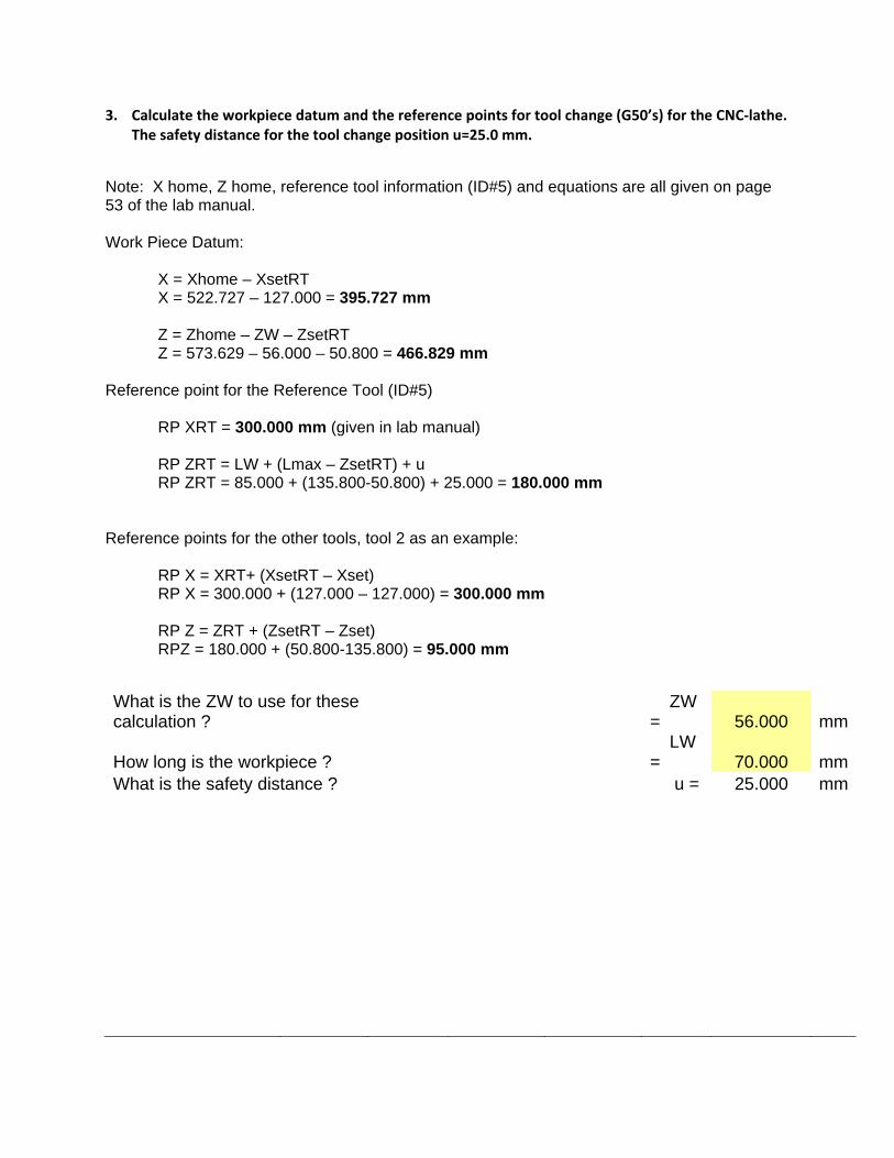
3. Calculate the workpiece datum and the reference points for tool change (G50’s) for the CNC‐lathe. The safety distance for the tool change position u=25.0 mm.
Note: X home, Z home, reference tool information (ID#5) and equations are all given on page 53 of the lab manual. Work Piece Datum: X = Xhome – XsetRT X = 522.727 – 127.000 = 395.727 mm Z = Zhome – ZW – ZsetRT Z = 573.629 – 56.000 – 50.800 = 466.829 mm Reference point for the Reference Tool (ID#5) RP XRT = 300.000 mm (given in lab manual) RP ZRT = LW + (Lmax – ZsetRT) + u RP ZRT = 85.000 + (135.800-50.800) + 25.000 = 180.000 mm Reference points for the other tools, tool 2 as an example: RP X = XRT+ (XsetRT – Xset) RP X = 300.000 + (127.000 – 127.000) = 300.000 mm RP Z = ZRT + (ZsetRT – Zset) RPZ = 180.000 + (50.800-135.800) = 95.000 mm
What is the ZW to use for these calculation ?
ZW = 56.000 mm
How long is the workpiece ?
LW = 70.000 mm
What is the safety distance ? u = 25.000 mm
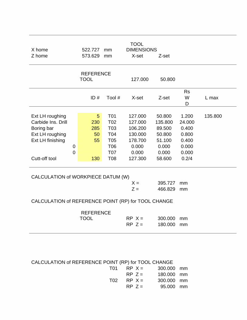
X home 522.727 mm TOOL DIMENSIONS
Z home 573.629 mm X-set Z-set
REFERENCE TOOL 127.000 50.800
Rs
ID # Tool # X-set Z-set W L max D
Ext LH roughing 5 T01 127.000 50.800 1.200 135.800 Carbide Ins. Drill 230 T02 127.000 135.800 24.000
Boring bar 285 T03 106.200 89.500 0.400
Ext LH roughing 50 T04 130.000 50.800 0.800
Ext LH finishing 55 T05 178.700 51.100 0.400
0 T06 0.000 0.000 0.000
0 T07 0.000 0.000 0.000
Cutt-off tool 130 T08 127.300 58.600 0.2/4
CALCULATION of WORKPIECE DATUM (W)
X = 395.727 mm
Z = 466.829 mm
CALCULATION of REFERENCE POINT (RP) for TOOL CHANGE
REFERENCE TOOL RP X = 300.000 mm
RP Z = 180.000 mm
CALCULATION of REFERENCE POINT (RP) for TOOL CHANGE
T01 RP X = 300.000 mm
RP Z = 180.000 mm
T02 RP X = 300.000 mm
RP Z = 95.000 mm
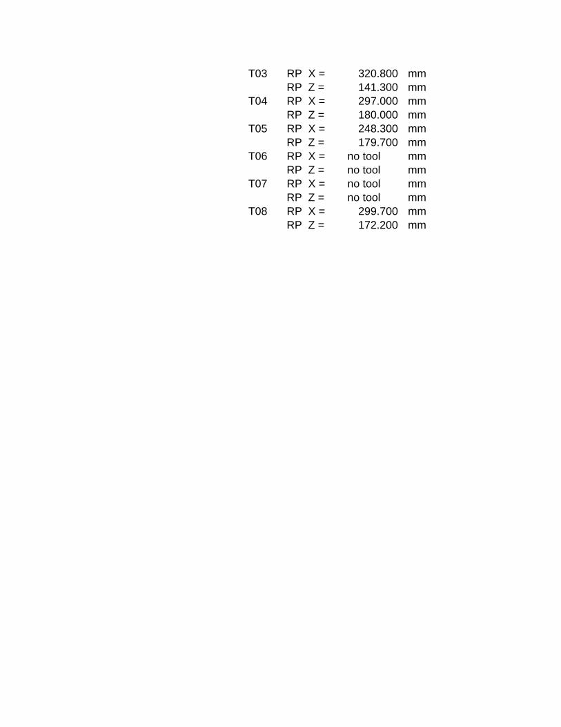
T03 RP X = 320.800 mm
RP Z = 141.300 mm
T04 RP X = 297.000 mm
RP Z = 180.000 mm
T05 RP X = 248.300 mm
RP Z = 179.700 mm
T06 RP X = no tool mm
RP Z = no tool mm
T07 RP X = no tool mm
RP Z = no tool mm
T08 RP X = 299.700 mm
RP Z = 172.200 mm
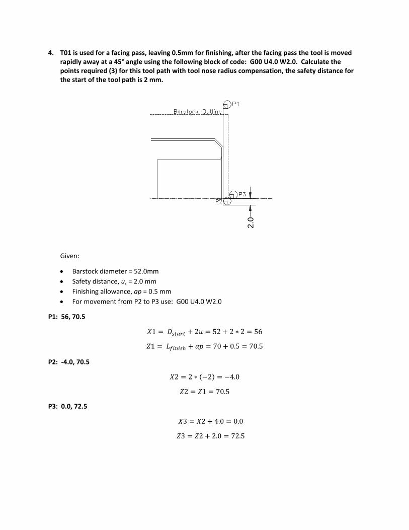
4. T01 is used for a facing pass, leaving 0.5mm for finishing, after the facing pass the tool is moved rapidly away at a 45° angle using the following block of code: G00 U4.0 W2.0. Calculate the points required (3) for this tool path with tool nose radius compensation, the safety distance for the start of the tool path is 2 mm.
Given:
Barstock diameter = 52.0mm
Safety distance, u, = 2.0 mm
Finishing allowance, ap = 0.5 mm
For movement from P2 to P3 use: G00 U4.0 W2.0
P1: 56, 70.5
1 2 52 2 ∗ 2 56
1 70 0.5 70.5
P2: ‐4.0, 70.5
2 2 ∗ 2 4.0
2 1 70.5
P3: 0.0, 72.5
3 2 4.0 0.0
3 2 2.0 72.5
2.0
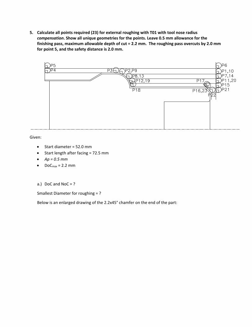
5. Calculate all points required (23) for external roughing with T01 with tool nose radius compensation. Show all unique geometries for the points. Leave 0.5 mm allowance for the finishing pass, maximum allowable depth of cut = 2.2 mm. The roughing pass overcuts by 2.0 mm for point 5, and the safety distance is 2.0 mm.
Given:
Start diameter = 52.0 mm
Start length after facing = 72.5 mm
Ap = 0.5 mm
DoCmax = 2.2 mm
a.) DoC and NoC = ?
Smallest Diameter for roughing = ?
Below is an enlarged drawing of the 2.2x45° chamfer on the end of the part:

252 32.01
22.2
4.54 → 5
252 32.01
25
2.0
P1: 48, 72.5
1 2 ∗ 52 2 ∗ 2 48.0
1 70 0.5 2 72.5 3
P2: 48, 30.53
2 1 48.0
ap=0.5 mm
Dfinal = 36 mm
Smallest
Diameter for
Roughing = Dmin
∆xα = 45°
2.2 mm
(drawing)
Dcorner
= 36 – 2.2(2) = 31.6
∆ tan2
∗ 0.2071
2 ∗ ∆ 32.01
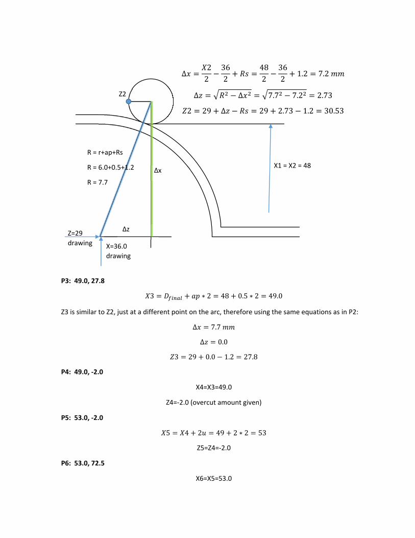
P3: 49.0, 27.8
3 ∗ 2 48 0.5 ∗ 2 49.0
Z3 is similar to Z2, just at a different point on the arc, therefore using the same equations as in P2:
∆ 7.7
∆ 0.0
3 29 0.0 1.2 27.8
P4: 49.0, ‐2.0
X4=X3=49.0
Z4=‐2.0 (overcut amount given)
P5: 53.0, ‐2.0
5 4 2 49 2 ∗ 2 53
Z5=Z4=‐2.0
P6: 53.0, 72.5
X6=X5=53.0
Z=29
drawing
Z2
∆x
∆z
X1 = X2 = 48
R = r+ap+Rs
R = 6.0+0.5+1.2
R = 7.7
∆22
362
482
362
1.2 7.2
∆ ∆ 7.7 7.2 2.73
2 29 ∆ 29 2.73 1.2 30.53
X=36.0
drawing
Z6=Z1=72.5
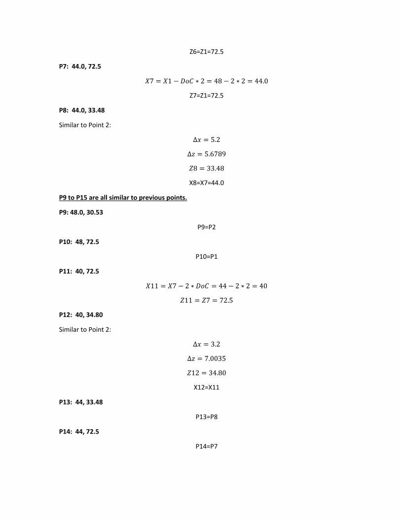
P7: 44.0, 72.5
7 1 ∗ 2 48 2 ∗ 2 44.0
Z7=Z1=72.5
P8: 44.0, 33.48
Similar to Point 2:
∆ 5.2
∆ 5.6789
8 33.48
X8=X7=44.0
P9 to P15 are all similar to previous points.
P9: 48.0, 30.53
P9=P2
P10: 48, 72.5
P10=P1
P11: 40, 72.5
11 7 2 ∗ 44 2 ∗ 2 40
11 7 72.5
P12: 40, 34.80
Similar to Point 2:
∆ 3.2
∆ 7.0035
12 34.80
X12=X11
P13: 44, 33.48
P13=P8
P14: 44, 72.5
P14=P7
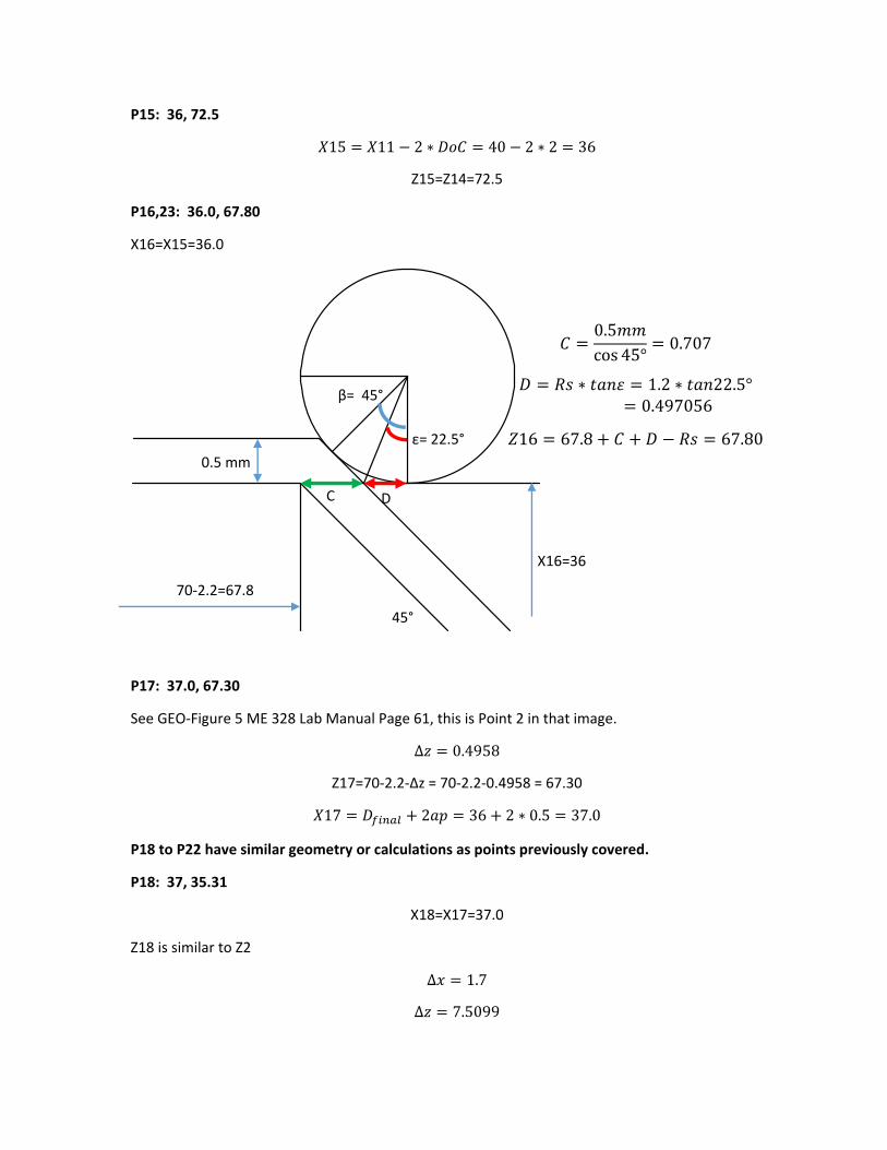
P15: 36, 72.5
15 11 2 ∗ 40 2 ∗ 2 36
Z15=Z14=72.5
P16,23: 36.0, 67.80
X16=X15=36.0
P17: 37.0, 67.30
See GEO‐Figure 5 ME 328 Lab Manual Page 61, this is Point 2 in that image.
∆ 0.4958
Z17=70‐2.2‐∆z = 70‐2.2‐0.4958 = 67.30
17 2 36 2 ∗ 0.5 37.0
P18 to P22 have similar geometry or calculations as points previously covered.
P18: 37, 35.31
X18=X17=37.0
Z18 is similar to Z2
∆ 1.7
∆ 7.5099
70‐2.2=67.8
0.5 mm
45°
X16=36
C D
β= 45°
ε= 22.5°
0.5cos 45°
0.707
∗ 1.2 ∗ 22.5°0.497056
16 67.8 67.80
18 35.31
P19: 40, 34.80
P19=P12
P20: 40, 72.5
P20=P11
P21: 32, 72.5
21 15 2 ∗ 36 2 ∗ 2 32
Z21=Z20=72.5
P22: 32, 69.80
Similart o P16
2.0
0.7071
0.497056
22 69.80
X22=X21=32
P23: 36, 67.80
P23=P16
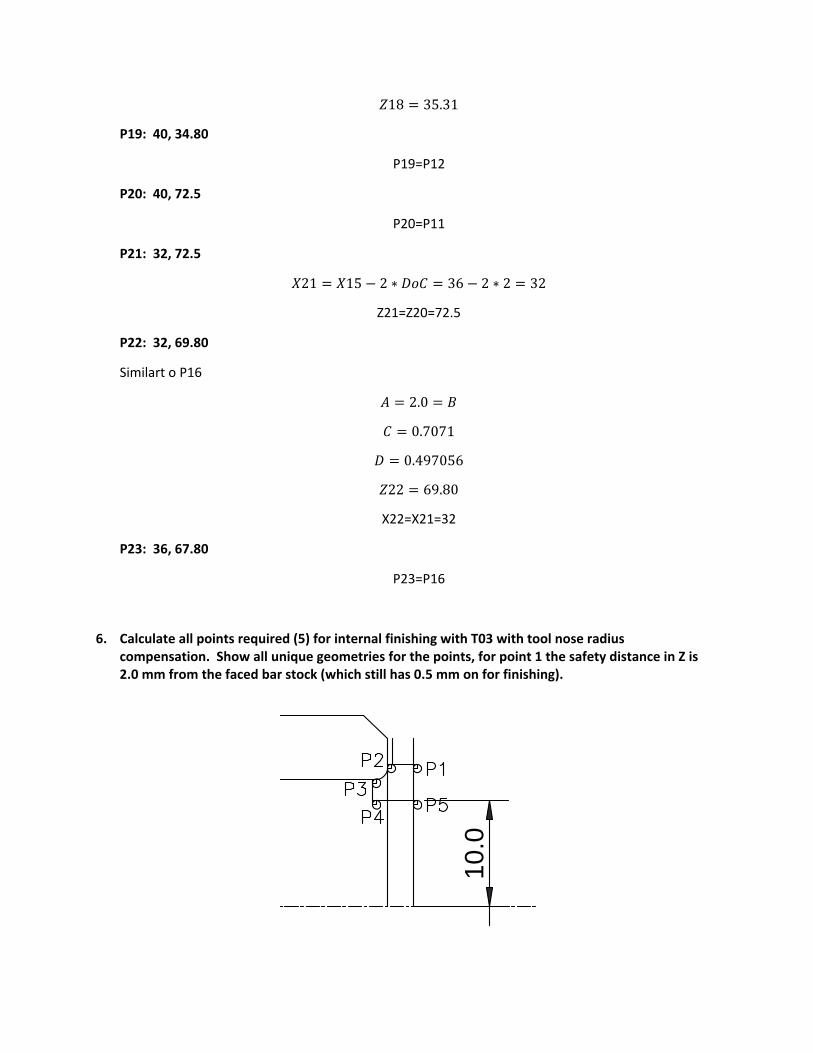
6. Calculate all points required (5) for internal finishing with T03 with tool nose radius compensation. Show all unique geometries for the points, for point 1 the safety distance in Z is 2.0 mm from the faced bar stock (which still has 0.5 mm on for finishing).
10.0
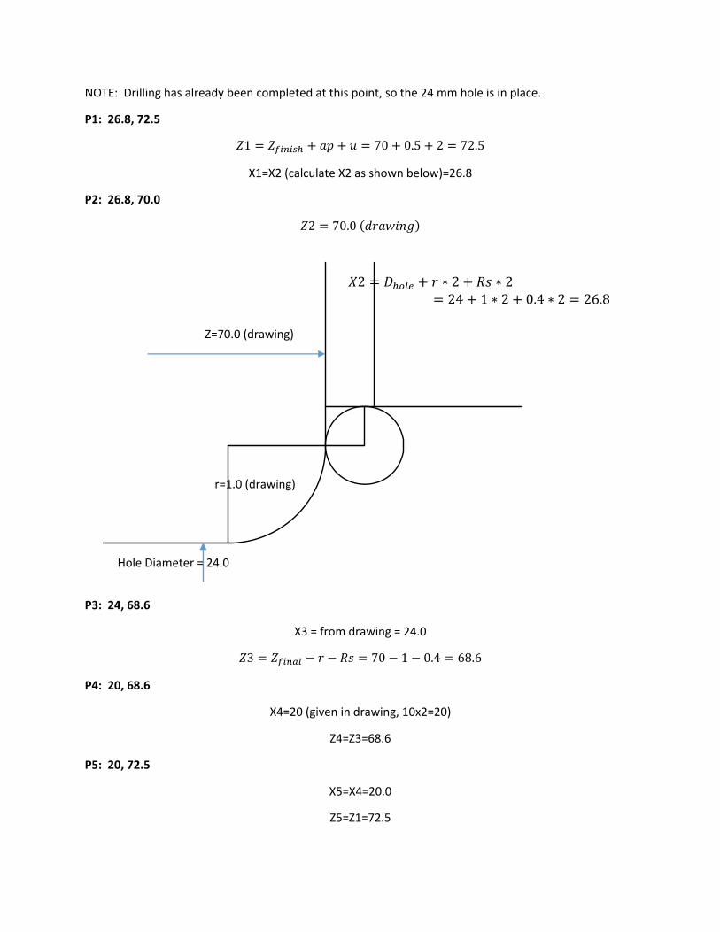
NOTE: Drilling has already been completed at this point, so the 24 mm hole is in place.
P1: 26.8, 72.5
1 70 0.5 2 72.5
X1=X2 (calculate X2 as shown below)=26.8
P2: 26.8, 70.0
2 70.0
P3: 24, 68.6
X3 = from drawing = 24.0
3 70 1 0.4 68.6
P4: 20, 68.6
X4=20 (given in drawing, 10x2=20)
Z4=Z3=68.6
P5: 20, 72.5
X5=X4=20.0
Z5=Z1=72.5
Z=70.0 (drawing)
Hole Diameter = 24.0
r=1.0 (drawing)
2 ∗ 2 ∗ 224 1 ∗ 2 0.4 ∗ 2 26.8

7. Calculate all points required (9) for external roughing with T04 with tool nose radius compensation. Show all unique geometries for the points. Leave 0.5 mm allowance for the finishing pass, maximum allowable depth of cut = 1.6 mm. The roughing pass overcuts by 1.5 mm for point 8, safety distance = 2.0 mm.
First the NoC and DoC need to be determined:
Known:
Start Diameter = 49 mm (left from T01)
Final Diameter = 42.0 mm (drawing)
ap = 0.5
Final roughed diameter = 42+0.5*2=43.0 mm
DoCmax = 1.6 mm
,2
49 4321.6
1.875 → 2
,2
49 4322
1.5
P1: 53, 25.316
1 2 ∗ ∗ 2 ∗ 48 0.5 ∗ 2 2 ∗ 2 53.0
Degree of the angle = ?
Using the dimensions from the drawing:
482
422
23 17.8→ 30°
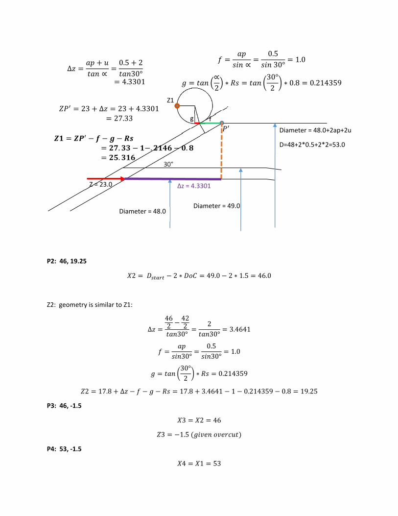
P2: 46, 19.25
2 2 ∗ 49.0 2 ∗ 1.5 46.0
Z2: geometry is similar to Z1:
∆
462
422
30°230°
3.4641
30°0.530°
1.0
30°2
∗ 0.214359
2 17.8 ∆ 17.8 3.4641 1 0.214359 0.8 19.25
P3: 46, ‐1.5
3 2 46
3 1.5
P4: 53, ‐1.5
4 1 53
Diameter = 48.0Diameter = 49.0
Diameter = 48.0+2ap+2u
D=48+2*0.5+2*2=53.0
30°
g f
∝0.530°
1.0
∝2
∗30°2
∗ 0.8 0.214359
23 ∆ 23 4.330127.33
∆∝
0.5 230°
4.3301
. . .
.
Z = 23.0 ∆z = 4.3301
Z1

4 3 1.5
P5: 53, 19.25
5 4 53.0
5 2 19.25
P6: 46, 19.25
P6 = P2
P7: 43, 16.65
7 ∗ 2 42 0.5 ∗ 2 43.0
Z7: similar to P2:
∆0.530°
0.866
1.0
0.214359
7 17.8 ∆ 17.8 0.866 1 0.214359 0.8 16.65
P8: 43, ‐1.5
8 7 43
8 3 1.5
P9: 53, ‐1.5
P9 = P4
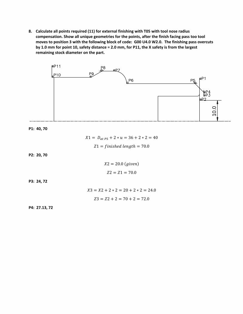
8. Calculate all points required (11) for external finishing with T05 with tool nose radius compensation. Show all unique geometries for the points, after the finish facing pass too tool moves to position 3 with the following block of code: G00 U4.0 W2.0. The finishing pass overcuts by 1.0 mm for point 10, safety distance = 2.0 mm, for P11, the X safety is from the largest remaining stock diameter on the part.
P1: 40, 70
1 2 ∗ 36 2 ∗ 2 40
1 70.0
P2: 20, 70
2 20.0
2 1 70.0
P3: 24, 72
3 2 2 ∗ 2 20 2 ∗ 2 24.0
3 2 2 70 2 72.0
P4: 27.13, 72
10.0

P5: 36, 67.566
This geometry is shown in the Figure on page 61 of the ME 328 Lab Manual for P2
5 36.0
∆ ∗2
0.4 0.4 ∗45°2
0.2343
5 ∆ 70 2.2 0.2343 67.566
P6: 36, 34.987
6 5 36.0
X = 31.6
Z=70.0
(part geometry
bottom corner
of chamfer)
∆z = u = 2.0
∆x = ∆z = 2.0
f sin0.445°
0.56568
0.56568 0.4 0.16568
45°0.16568
45°0.2343
4 31.6 2 ∗ ∆ 2 ∗ 31.6 2 ∗ 2 2 ∗ 0.2343 27.13
4 70.0 2.0 72.0
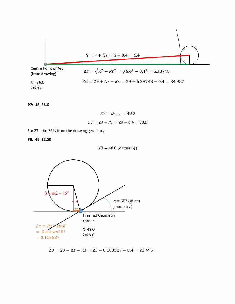
P7: 48, 28.6
7 48.0
7 29 29 0.4 28.6
For Z7: the 29 is from the drawing geometry.
P8: 48, 22.50
8 48.0
Centre Point of Arc
(from drawing)
X = 36.0
Z=29.0
6 0.4 6.4
∆ 6.4 0.4 6.38748
6 29 ∆ 29 6.38748 0.4 34.987
Finished Geometry
corner
X=48.0
Z=23.0
α = 30° (given geometry)
β = α/2 = 15°
∆ ∗0.4 ∗ 15°0.103527
∆z
8 23 ∆ 23 0.103527 0.4 22.496

P9: 42, 17.30
Similar to P8:
9 42.0
9 17.8 ∆ 17.8 0.103527 0.4 17.296
P10: 42, ‐1.0
10 9 42.0
10 1.0
P11: 52, ‐1.0
11 , 2 ∗ 48 2 ∗ 2 52.0
11 10 1.0
9. Calculate all required points (7) for T08 (part off tool), with tool nose radius compensation. Show the geometry for all points, initial safety distance in X (P1) is 2.0 mm from the initial barstock diameter, all other safety distances = 2.0 mm. Initial plunge cut (P2) has an X coordinate = 37.
P1: 56, 0.0
1 2 ∗ 52 2 ∗ 2 56.0
1 0.0
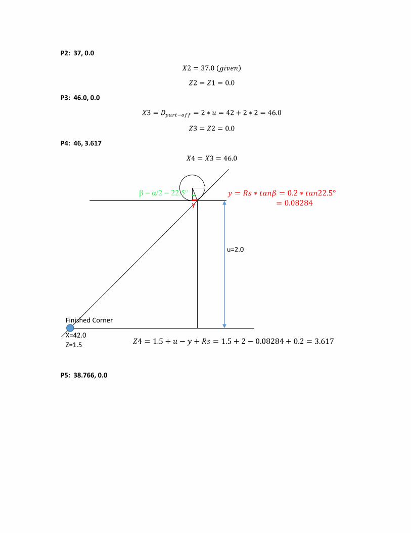
P2: 37, 0.0
2 37.0
2 1 0.0
P3: 46.0, 0.0
3 2 ∗ 42 2 ∗ 2 46.0
3 2 0.0
P4: 46, 3.617
4 3 46.0
P5: 38.766, 0.0
Finished Corner
X=42.0
Z=1.5
u=2.0
β = α/2 = 22.5° y
∗ 0.2 ∗ 22.5°0.08284
4 1.5 1.5 2 0.08284 0.2 3.617
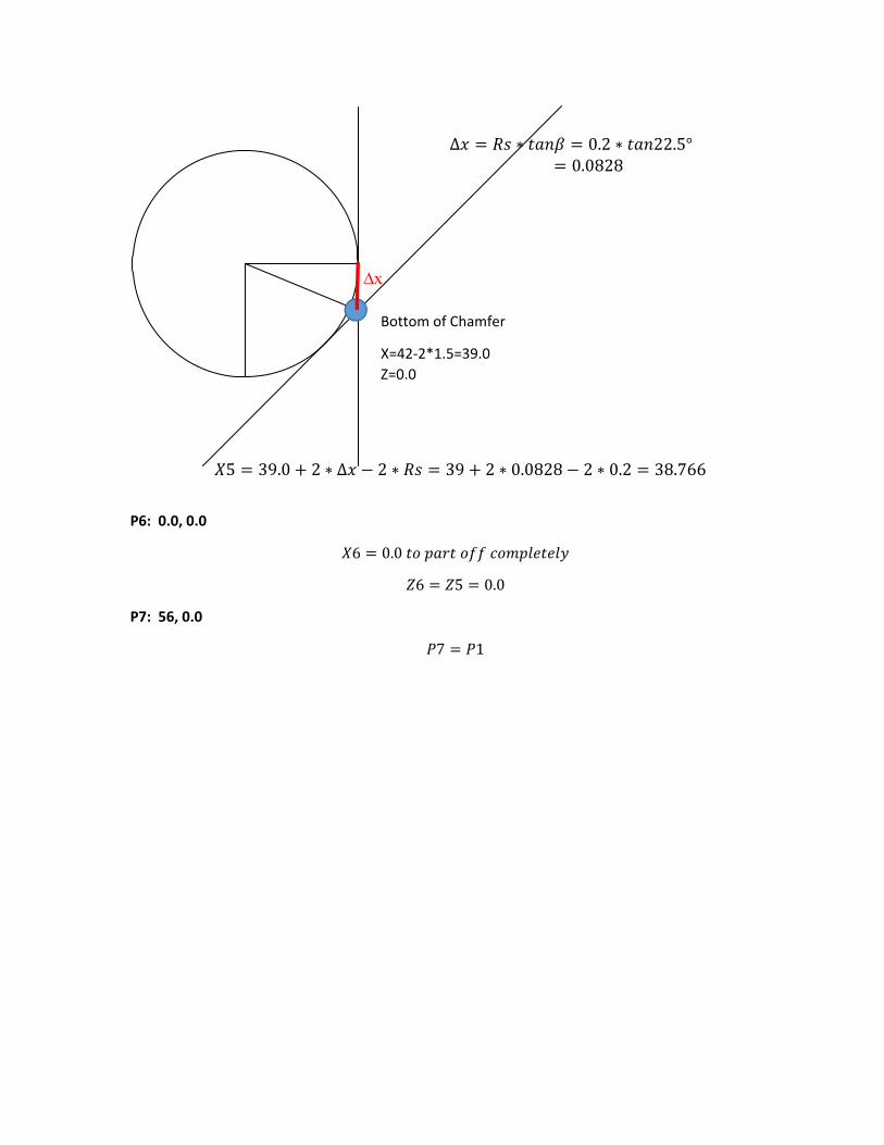
P6: 0.0, 0.0
6 0.0
6 5 0.0
P7: 56, 0.0
7 1
Bottom of Chamfer
X=42‐2*1.5=39.0
Z=0.0
∆x
∆ ∗ 0.2 ∗ 22.5°0.0828
5 39.0 2 ∗ ∆ 2 ∗ 39 2 ∗ 0.0828 2 ∗ 0.2 38.766
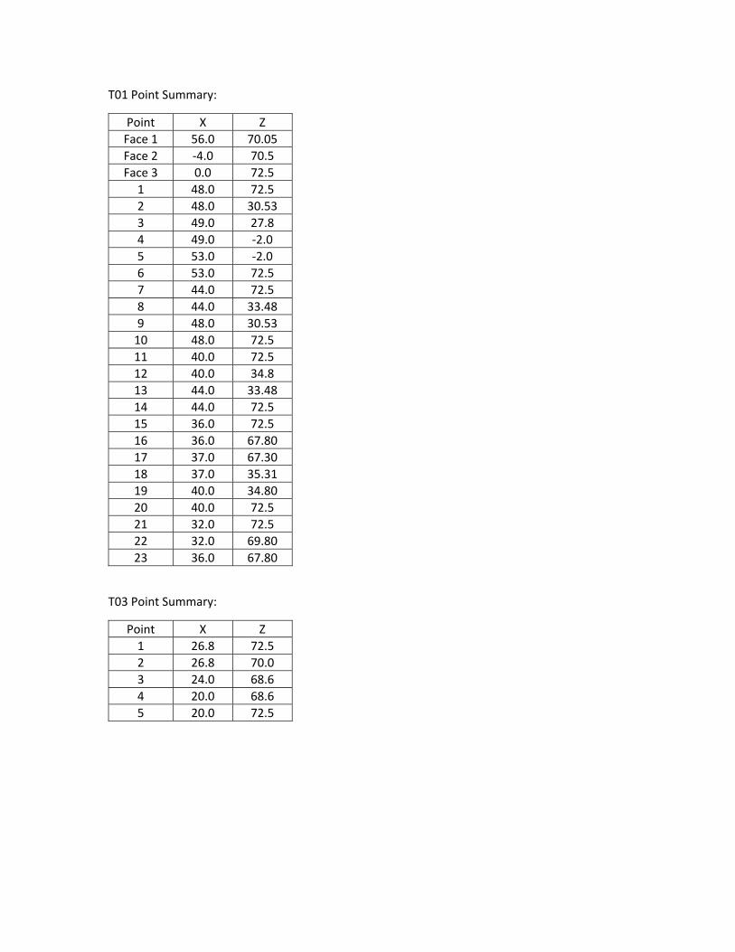
T01 Point Summary:
Point X Z
Face 1 56.0 70.05
Face 2 ‐4.0 70.5
Face 3 0.0 72.5
1 48.0 72.5
2 48.0 30.53
3 49.0 27.8
4 49.0 ‐2.0
5 53.0 ‐2.0
6 53.0 72.5
7 44.0 72.5
8 44.0 33.48
9 48.0 30.53
10 48.0 72.5
11 40.0 72.5
12 40.0 34.8
13 44.0 33.48
14 44.0 72.5
15 36.0 72.5
16 36.0 67.80
17 37.0 67.30
18 37.0 35.31
19 40.0 34.80
20 40.0 72.5
21 32.0 72.5
22 32.0 69.80
23 36.0 67.80
T03 Point Summary:
Point X Z
1 26.8 72.5
2 26.8 70.0
3 24.0 68.6
4 20.0 68.6
5 20.0 72.5
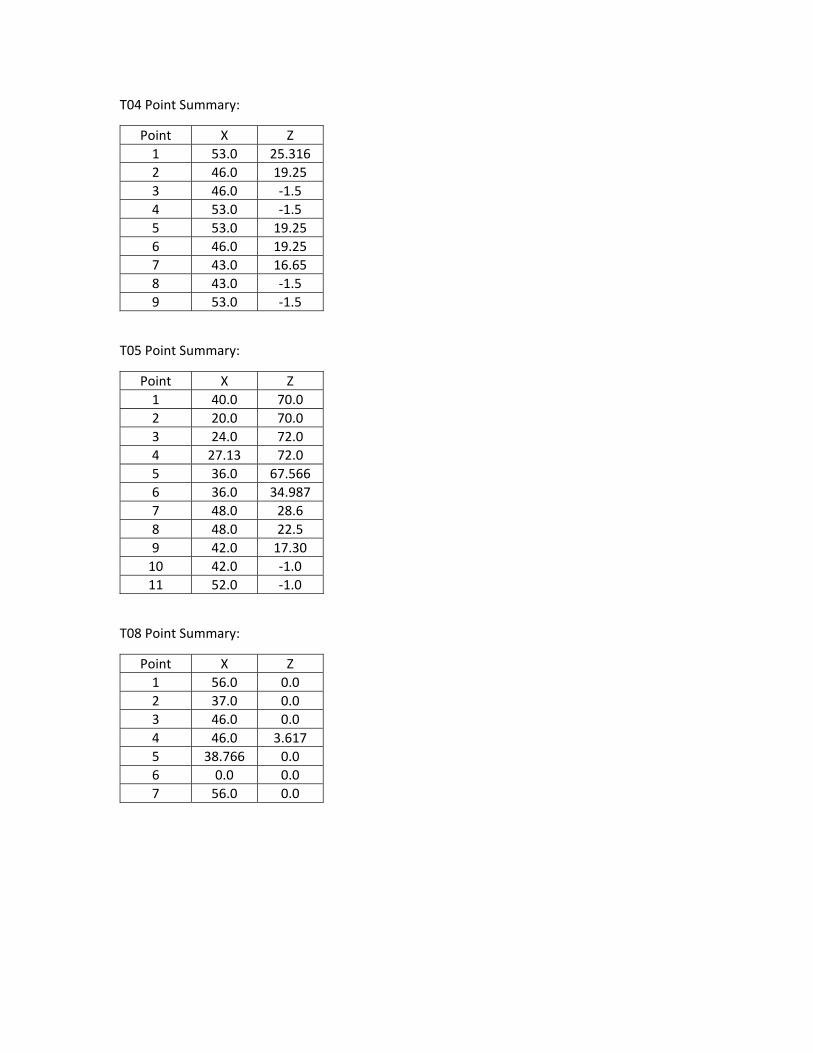
T04 Point Summary:
Point X Z
1 53.0 25.316
2 46.0 19.25
3 46.0 ‐1.5
4 53.0 ‐1.5
5 53.0 19.25
6 46.0 19.25
7 43.0 16.65
8 43.0 ‐1.5
9 53.0 ‐1.5
T05 Point Summary:
Point X Z
1 40.0 70.0
2 20.0 70.0
3 24.0 72.0
4 27.13 72.0
5 36.0 67.566
6 36.0 34.987
7 48.0 28.6
8 48.0 22.5
9 42.0 17.30
10 42.0 ‐1.0
11 52.0 ‐1.0
T08 Point Summary:
Point X Z
1 56.0 0.0
2 37.0 0.0
3 46.0 0.0
4 46.0 3.617
5 38.766 0.0
6 0.0 0.0
7 56.0 0.0
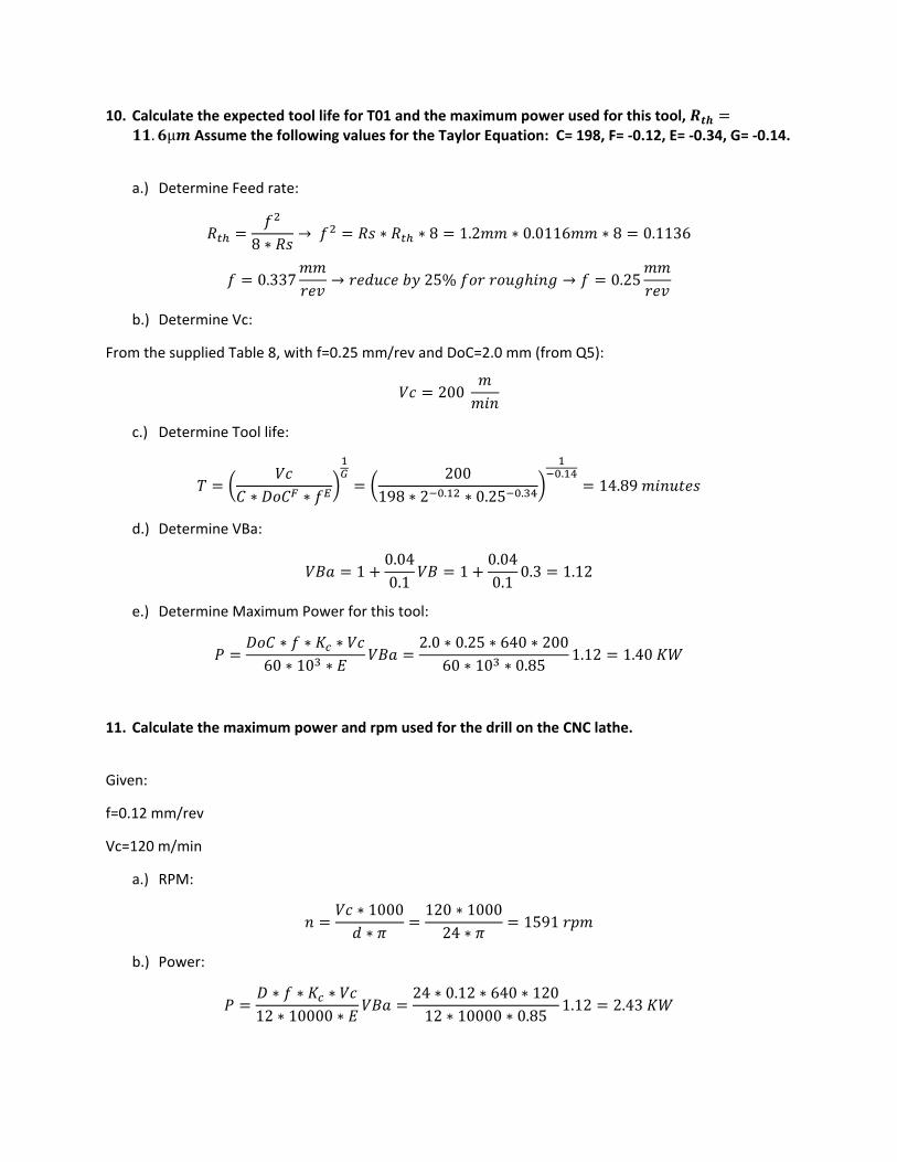
10. Calculate the expected tool life for T01 and the maximum power used for this tool, . μ Assume the following values for the Taylor Equation: C= 198, F= ‐0.12, E= ‐0.34, G= ‐0.14.
a.) Determine Feed rate:
8 ∗→ ∗ ∗ 8 1.2 ∗ 0.0116 ∗ 8 0.1136
0.337 → 25% → 0.25
b.) Determine Vc:
From the supplied Table 8, with f=0.25 mm/rev and DoC=2.0 mm (from Q5):
200
c.) Determine Tool life:
∗ ∗200
198 ∗ 2 . ∗ 0.25 .
.14.89
d.) Determine VBa:
10.040.1
10.040.1
0.3 1.12
e.) Determine Maximum Power for this tool:
∗ ∗ ∗60 ∗ 10 ∗
2.0 ∗ 0.25 ∗ 640 ∗ 20060 ∗ 10 ∗ 0.85
1.12 1.40
11. Calculate the maximum power and rpm used for the drill on the CNC lathe.
Given:
f=0.12 mm/rev
Vc=120 m/min
a.) RPM:
∗ 1000∗
120 ∗ 100024 ∗
1591
b.) Power:
∗ ∗ ∗12 ∗ 10000 ∗
24 ∗ 0.12 ∗ 640 ∗ 12012 ∗ 10000 ∗ 0.85
1.12 2.43
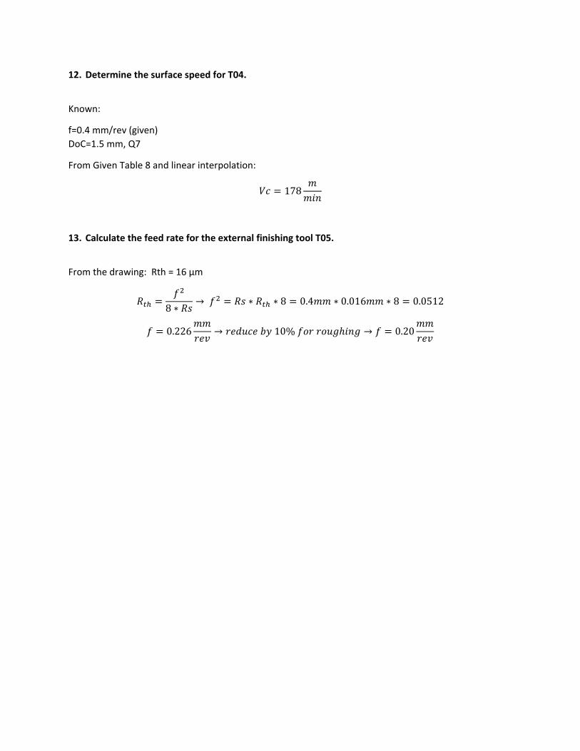
12. Determine the surface speed for T04.
Known:
f=0.4 mm/rev (given)
DoC=1.5 mm, Q7
From Given Table 8 and linear interpolation:
178
13. Calculate the feed rate for the external finishing tool T05.
From the drawing: Rth = 16 µm
8 ∗→ ∗ ∗ 8 0.4 ∗ 0.016 ∗ 8 0.0512
0.226 → 10% → 0.20
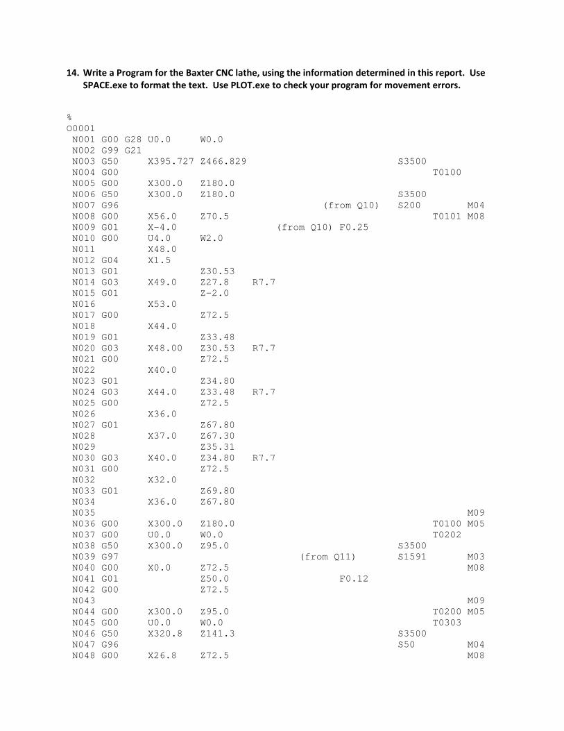
14. Write a Program for the Baxter CNC lathe, using the information determined in this report. Use SPACE.exe to format the text. Use PLOT.exe to check your program for movement errors.
% O0001 N001 G00 G28 U0.0 W0.0 N002 G99 G21 N003 G50 X395.727 Z466.829 S3500 N004 G00 T0100 N005 G00 X300.0 Z180.0 N006 G50 X300.0 Z180.0 S3500 N007 G96 (from Q10) S200 M04 N008 G00 X56.0 Z70.5 T0101 M08 N009 G01 X-4.0 (from Q10) F0.25 N010 G00 U4.0 W2.0 N011 X48.0 N012 G04 X1.5 N013 G01 Z30.53 N014 G03 X49.0 Z27.8 R7.7 N015 G01 Z-2.0 N016 X53.0 N017 G00 Z72.5 N018 X44.0 N019 G01 Z33.48 N020 G03 X48.00 Z30.53 R7.7 N021 G00 Z72.5 N022 X40.0 N023 G01 Z34.80 N024 G03 X44.0 Z33.48 R7.7 N025 G00 Z72.5 N026 X36.0 N027 G01 Z67.80 N028 X37.0 Z67.30 N029 Z35.31 N030 G03 X40.0 Z34.80 R7.7 N031 G00 Z72.5 N032 X32.0 N033 G01 Z69.80 N034 X36.0 Z67.80 N035 M09 N036 G00 X300.0 Z180.0 T0100 M05 N037 G00 U0.0 W0.0 T0202 N038 G50 X300.0 Z95.0 S3500 N039 G97 (from Q11) S1591 M03 N040 G00 X0.0 Z72.5 M08 N041 G01 Z50.0 F0.12 N042 G00 Z72.5 N043 M09 N044 G00 X300.0 Z95.0 T0200 M05 N045 G00 U0.0 W0.0 T0303 N046 G50 X320.8 Z141.3 S3500 N047 G96 S50 M04 N048 G00 X26.8 Z72.5 M08
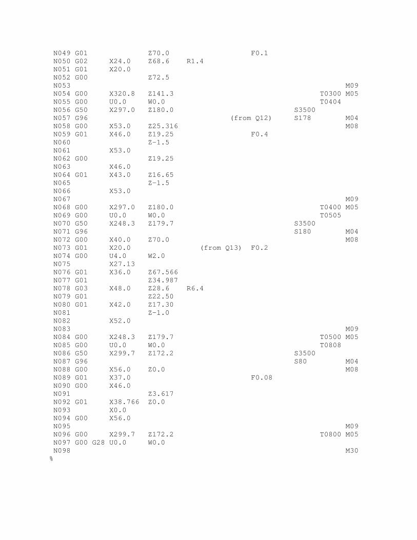
N049 G01 Z70.0 F0.1 N050 G02 X24.0 Z68.6 R1.4 N051 G01 X20.0 N052 G00 Z72.5 N053 M09 N054 G00 X320.8 Z141.3 T0300 M05 N055 G00 U0.0 W0.0 T0404 N056 G50 X297.0 Z180.0 S3500 N057 G96 (from Q12) S178 M04 N058 G00 X53.0 Z25.316 M08 N059 G01 X46.0 Z19.25 F0.4 N060 Z-1.5 N061 X53.0 N062 G00 Z19.25 N063 X46.0 N064 G01 X43.0 Z16.65 N065 Z-1.5 N066 X53.0 N067 M09 N068 G00 X297.0 Z180.0 T0400 M05 N069 G00 U0.0 W0.0 T0505 N070 G50 X248.3 Z179.7 S3500 N071 G96 S180 M04 N072 G00 X40.0 Z70.0 M08 N073 G01 X20.0 (from Q13) F0.2 N074 G00 U4.0 W2.0 N075 X27.13 N076 G01 X36.0 Z67.566 N077 G01 Z34.987 N078 G03 X48.0 Z28.6 R6.4 N079 G01 Z22.50 N080 G01 X42.0 Z17.30 N081 Z-1.0 N082 X52.0 N083 M09 N084 G00 X248.3 Z179.7 T0500 M05 N085 G00 U0.0 W0.0 T0808 N086 G50 X299.7 Z172.2 S3500 N087 G96 S80 M04 N088 G00 X56.0 Z0.0 M08 N089 G01 X37.0 F0.08 N090 G00 X46.0 N091 Z3.617 N092 G01 X38.766 Z0.0 N093 X0.0 N094 G00 X56.0 N095 M09 N096 G00 X299.7 Z172.2 T0800 M05 N097 G00 G28 U0.0 W0.0 N098 M30 %
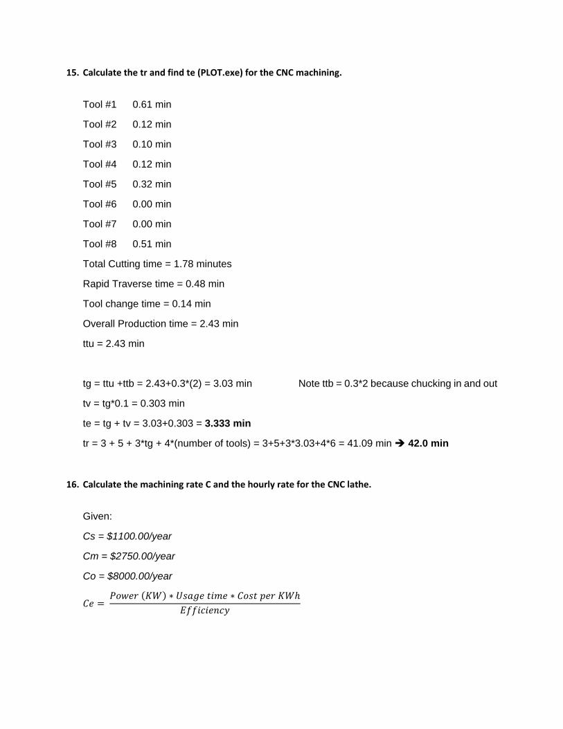
15. Calculate the tr and find te (PLOT.exe) for the CNC machining.
Tool #1 0.61 min
Tool #2 0.12 min
Tool #3 0.10 min
Tool #4 0.12 min
Tool #5 0.32 min
Tool #6 0.00 min
Tool #7 0.00 min
Tool #8 0.51 min
Total Cutting time = 1.78 minutes
Rapid Traverse time = 0.48 min
Tool change time = 0.14 min
Overall Production time = 2.43 min
ttu = 2.43 min
tg = ttu +ttb = 2.43+0.3*(2) = 3.03 min Note ttb = 0.3*2 because chucking in and out
tv = tg*0.1 = 0.303 min
te = tg + tv = 3.03+0.303 = 3.333 min
tr = 3 + 5 + 3*tg + 4*(number of tools) = 3+5+3*3.03+4*6 = 41.09 min 42.0 min
16. Calculate the machining rate C and the hourly rate for the CNC lathe.
Given:
Cs = $1100.00/year
Cm = $2750.00/year
Co = $8000.00/year
∗ ∗

10.00 ∗0.745699872
7.457
1
∗8
∗5
∗48
1920
7.457 ∗ 1920 ∗ 0.370.85
$6,232.30/
$50,000.004
$12,500.00/
∑
Mv = Mean Value
Sv = Start Value
For Year 1:
Svyear1 = $50,000.00
2$50,000
$12,5002
$43,750.00
I = Interest
∗ $43,750 ∗ 0.024 $1,050.00
For Year 2:
Svyear2 = Svyear1 – Cw = $50,000-$12,500 = $37,500.00
2$37,500
$12,5002
$31,250.00
I = Interest
∗ $31,250 ∗ 0.024 $750.00
Similarily for Years 3 and 4:
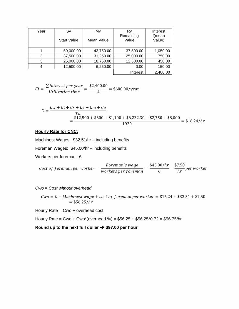
Year Sv Mv Rv Interest
Start Value Mean Value Remaining
Value f(mean Value)
1 50,000.00 43,750.00 37,500.00 1,050.00 2 37,500.00 31,250.00 25,000.00 750.00 3 25,000.00 18,750.00 12,500.00 450.00
4 12,500.00 6,250.00 0.00 150.00
Interest 2,400.00
∑
$2,400.00
4$600.00/
$12,500 $600 $1,100 $6,232.30 $2,750 $8,0001920
$16.24/
Hourly Rate for CNC:
Machinest Wages: $32.51/hr – including benefits
Foreman Wages: $45.00/hr – including benefits
Workers per foreman: 6
$45.00/
6$7.50
Cwo = Cost without overhead
$16.24 $32.51 $7.50$56.25/
Hourly Rate = Cwo + overhead cost
Hourly Rate = Cwo + Cwo*(overhead %) = $56.25 + $56.25*0.72 = $96.75/hr
Round up to the next full dollar $97.00 per hour
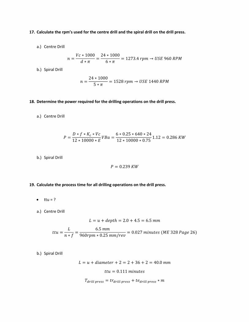
17. Calculate the rpm’s used for the centre drill and the spiral drill on the drill press.
a.) Centre Drill
∗ 1000∗
24 ∗ 10006 ∗
1273.4 → 960
b.) Spiral Drill
24 ∗ 10005 ∗
1528 → 1440
18. Determine the power required for the drilling operations on the drill press.
a.) Centre Drill
∗ ∗ ∗12 ∗ 10000 ∗
6 ∗ 0.25 ∗ 640 ∗ 2412 ∗ 10000 ∗ 0.75
1.12 0.286
b.) Spiral Drill
0.239
19. Calculate the process time for all drilling operations on the drill press.
ttu = ?
a.) Centre Drill
2.0 4.5 6.5
∗6.5
960 ∗ 0.25 /0.027 328 26
b.) Spiral Drill
2 2 36 2 40.0
0.111
∗
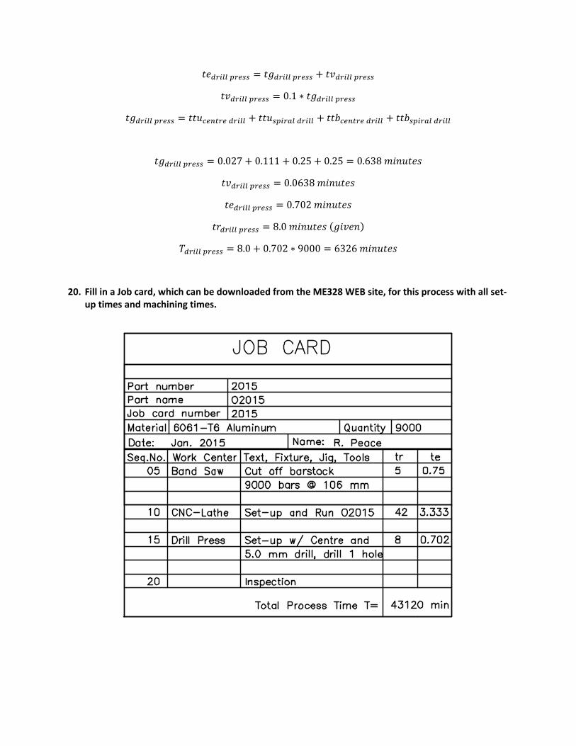
0.1 ∗
0.027 0.111 0.25 0.25 0.638
0.0638
0.702
8.0
8.0 0.702 ∗ 9000 6326
20. Fill in a Job card, which can be downloaded from the ME328 WEB site, for this process with all set‐up times and machining times.
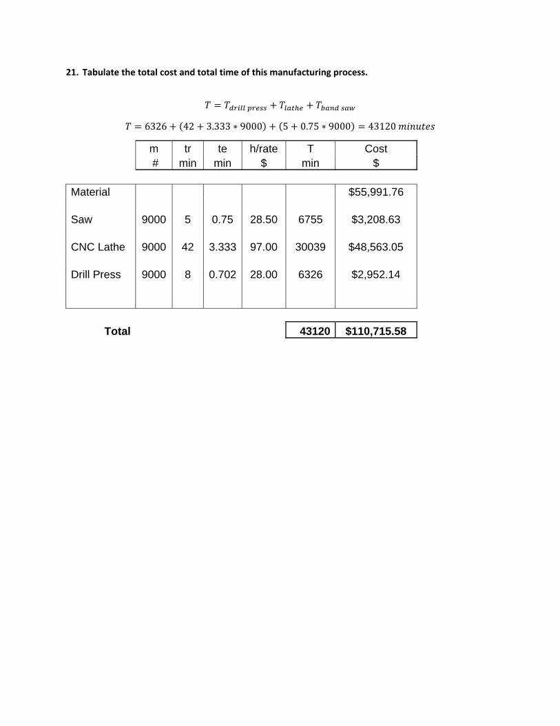
21. Tabulate the total cost and total time of this manufacturing process.
6326 42 3.333 ∗ 9000 5 0.75 ∗ 9000 43120
m tr te h/rate T Cost # min min $ min $
Material $55,991.76 Saw 9000 5 0.75 28.50 6755 $3,208.63 CNC Lathe 9000 42 3.333 97.00 30039 $48,563.05 Drill Press 9000 8 0.702 28.00 6326 $2,952.14
Total 43120 $110,715.58