Embed Size (px)
Citation preview

Measurement and Evaluation of Visibility Experiments for Powered Industrial Vehicles
Roger BostelmanU.S DEPARTMENT OF COMMERCE
National Institute of Standards and Technology Intelligent Systems Division
Gaithersburg, MD 20899-8230
Li Peng LiangUniversity of Maryland, College Park
College Park, MD 20742
NISTIR 7837

NISTIR 7837
Measurement and Evaluation of Visibility Experiments for Powered Industrial Vehicles
Roger BostelmanU.S DEPARTMENT OF COMMERCE
National Institute of Standards and Technology Intelligent Systems Division
Gaithersburg, MD 20899-8230
Li Peng LiangUniversity of Maryland, College Park
College Park, MD 20742
December 2011
U.S. DEPARTMENT OF COMMERCE John Bryson, Secretary
NATIONAL INSTITUTE OF STANDARDS AND TECHNOLOGY Patrick D. Gallagher, Under Secretary for Standards and Technology and Director

1

2
Abstract
Powered industrial vehicles, such as forklifts, are widely used in manufacturing and other
industries. Potential safety issues exist due to limitations in the operator‟s ability to see all
around the vehicle. Areas the operator cannot see are called non-visible vehicle regions. Non-
visible regions for operators of powered industrial vehicles are mainly caused by vehicle
obstructions The regions are required to meet certain criteria specified by standards. American
National Standard Institute (ANSI)/Industrial Truck Standards Development Foundation
(ITSDF) ANSI/ITSDF B56.5, ANSI/ITSDF B56.11.6, and International Organization for
Standardization/Draft International Standard (ISO/DIS) 13564-1 standards require measurement
and evaluation of visibility from powered industrial vehicles. The National Institute of Standards
and Technology‟s (NIST) Intelligent System Division has been researching advanced 2D and 3D
imaging sensors for improving both automated and manned forklift safety. Improvements are
expected to provide 3D obstacle detection for both vehicle types. It is important to understand
non-visible region locations initially, since that would then determine what type of 3D imagers
would be required and where the sensors would be mounted. Visibility of a forklift was
evaluated at NIST by following the above ANSI and ISO standards through 11 tests which set
criteria based on the patterns of shadows cast when the forklift does not carry any load. Also,
new test methods were created and tested. The new test methods were based on the forklift
carrying loads and using standard sized test pieces and a mannequin. The NIST experiments,
tests methods, and results are detailed in this report. This report will then serve as a basis for
further advanced visibility and semi-automated powered industrial vehicle safety performance
measurements and test methods development.
Keywords: ANSI/ITSDF B56 standards, visibility, powered industrial vehicles, forklift,
safety, recommendations

3
Table of Contents INTRODUCTION ......................................................................................................................................................... 4
BACKGROUND ........................................................................................................................................................... 6
EXPERIMENTAL SETUP ........................................................................................................................................... 7
EXPERIMENTS .......................................................................................................................................................... 14
EXPERIMENTAL RESULTS .................................................................................................................................... 16
RESULTS OF ADDITIONAL EXPERIMENTS ........................................................................................................ 19
RECOMMENDED IMPROVEMENTS TO CURRENT STANDARDS ................................................................... 23
ISO/DIS 13564-1 and ANSI/ITSDF B56.11.6 .................................................................................................. 23
ISO 5353: 1995 ............................................................................................................................................. 29
SUMMARY AND CONCLUSIONS .......................................................................................................................... 30
ACKNOWLEDGEMENTS ......................................................................................................................................... 31
REFERENCES ............................................................................................................................................................ 31
APPENDICES ............................................................................................................................................................. 33
Appendix 1 - Modified SIP Apparatus Design .................................................................................................. 33
Appendix 2 - Forklift Test Orientation and Patterns of Shadows ........................................................................ 34
Appendix 3 - Recent and planned visibility efforts ............................................................................................ 36
List of Tables Table 1. Forklift specifications …………………………………………………………………. 7
Table 2. Description of visibility tests …………………………………………………………. 14
Table 3. Test results of travelling mode of forklift ……………………………………………. 18
Table 4. Test results for maneuvering mode of forklift …………………………………...…… 18
Table 5. Test results with forklift carrying a pallet of boxes ………………………………….. 20
Table 6. Results when fork arms were raised to 117mm above floor ………………………….. 21

4
INTRODUCTION
Powered industrial vehicles are widely used in many industries. There are over 1 million forklifts
and nearly 2000 automated guided vehicles (AGVs) in use in the United States. The number of
forklift operators is estimated to be 2 million (6 million including part time operators) [1].
Forklifts are necessary vehicles for materials handling and delivering. However, forklifts can be
a hazard to drivers and pedestrians if not operated properly or if non-visible regions due to
forklift structure and loads they carry are not addressed. Training and forklift activity
monitoring are being addressed through driver education, tracking technology, and supervision.
According to American National Standard Institute (ANSI)/Industrial Truck Standards
Development Foundation (ITSDF) [2] B56.1, the manned industrial lift truck operator is
responsible for vehicle control. Safe speeds, driver training, and other vehicle operator
responsibilities must also be adhered to according to the standard. Visibility from within
forklifts or other powered industrial vehicles is typically measured by the vehicle manufacturer
according to visibility standards, such as International Organization for Standardization/Draft
International Standard (ISO/DIS) [3] ISO/DIS 13564-1 [4] and ANSI/ITSDF B56.11.6 [5]
which allow up to 20 % non-visible regions. Non-visibility is being addressed through
commercial, off-the-shelf forklift tracking, cameras, barriers, etc. [6] However, even with these
operational and visibility solutions and standards, forklift accidents frequently occur. Accidents
statistics involving forklifts were presented at the 2010 “Towards Improved Forklift Safety”
workshop and summarized in [6]. For example:
OSHA estimates that there are 110 000 accidents each year.
Almost 80% of forklift accidents involve a pedestrian.
According to OSHA, approximately 70 % of all accidents reported could have been
avoided with proper safety procedures.
In the next generation manufacturing facility, the Intelligent Systems Division (ISD) at the
National Institute of Standards and Technology (NIST) envisions increased human-vehicle
collaboration [7] Current forklift visibility standard criteria are likely insufficient in providing
guidance for this kind of operation with respect to safety. Therefore, NIST ISD has been
researching advanced 2D and 3D imaging sensors for viewing the local environment of AGVs
and recently, to address the issue of forklift safety. Several safety technology implementation
concepts for manufacturing vehicles were presented in [6] including use of 3D imagers mounted
on a forklift and used as non-visible region detection devices to assist drivers. It may be feasible
to integrate the 3D sensor information with driver alerts (e.g., audible, visual, etc.) and/or to
provide semi-autonomous slow/stop functionality to prevent accidents when the driver doesn‟t
see the hazard.
The test methods in current visibility standards do not determine exactly where non-visible
regions occur, only that they do or do not occur. These non-visible regions must be known for
sensor manufacturers and integrators to determine what 2D and 3D imaging devices are useful
5
for this safety application and where they are best mounted on industrial vehicles to provide the
most cost effective solution. It is also unclear in the current visibility standards, how well the
test method results determine the non-visible regions. Many lamps are used simultaneously for
most standard tests to illuminate an area resulting in few shadows created by vehicle obstructions
and therefore, visibility appears to meet visibility standard requirements. However, it is obvious
to a viewer sitting in the vehicle driver‟s seat that vehicle obstructions exist.
In order to fully understand how visibility standard test methods determine non-visible regions
and if necessary, how these methods can or should be improved, ISD researchers first
implemented the visibility standards on a forklift. The results provided the basis for
recommendations for improving current visibility standards. One key result is that the standard
test method of turning on all the lights at the same time did not effectively simulate the positions
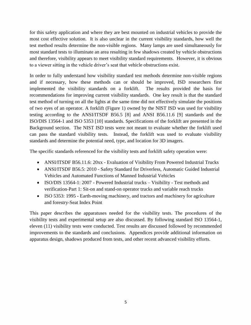
of two eyes of an operator. A forklift (Figure 1) owned by the NIST ISD was used for visibility
testing according to the ANSI/ITSDF B56.5 [8] and ANSI B56.11.6 [9] standards and the
ISO/DIS 13564-1 and ISO 5353 [10] standards. Specifications of the forklift are presented in the
Background section. The NIST ISD tests were not meant to evaluate whether the forklift used
can pass the standard visibility tests. Instead, the forklift was used to evaluate visibility
standards and determine the potential need, type, and location for 3D imagers.
The specific standards referenced for the visibility tests and forklift safety operation were:
ANSI/ITSDF B56.11.6: 20xx - Evaluation of Visibility From Powered Industrial Trucks
ANSI/ITSDF B56.5: 2010 - Safety Standard for Driverless, Automatic Guided Industrial
Vehicles and Automated Functions of Manned Industrial Vehicles
ISO/DIS 13564-1: 2007 - Powered Industrial trucks – Visibility - Test methods and
verification-Part 1: Sit-on and stand-on operator trucks and variable reach trucks
ISO 5353: 1995 - Earth-moving machinery, and tractors and machinery for agriculture
and forestry-Seat Index Point
This paper describes the apparatuses needed for the visibility tests. The procedures of the
visibility tests and experimental setup are also discussed. By following standard ISO 13564-1,
eleven (11) visibility tests were conducted. Test results are discussed followed by recommended
improvements to the standards and conclusions. Appendices provide additional information on
apparatus design, shadows produced from tests, and other recent advanced visibility efforts.
6
Figure 1. Forklift1 used for Visibility experiments.
BACKGROUND
Draft International Standard ISO/DIS 13564-1 is based on the current ANSI B56.11.6 standard
for visibility tests of powered industrial vehicles. ISO/DIS 13564-1 is now being rewritten.
Upon completion of the ISO standard, the ANSI 56.11.6 standard will again be addressed and
updated according to the latest ISO 13564-1 standard.
Both ISO and ANSI standards state that the visibility of the operator sitting inside the forklift is
required to meet certain criteria - generally to have 20 % visibility of specific sized targets placed
at specified locations. ISO/DIS 13564-1 and ISO 5353 were followed and applied to the ISD
forklift. A light source array is used to determine obstructed lines-of-sight from a position
comparable to that of an operator‟s eyes. ISO/DIS 13564-1 specifies the exact locations of the
light source array to simulate the positions of the operator‟s eyes. This point is critical since (a)
the operator can move his/her head for better visibility and (b) the operator also has peripheral
vision. For (a), the standard tests mandate the use of a 13 lamp array which simulates operator
head movement. For (a) and (b), the standard tests mandate rotating the lamp array about a
known point.
The location of the lamp array is based on a reference point called the Seat Index Point (SIP)
located on an SIP apparatus. The SIP apparatus is specified in and was fabricated at ISD
following ISO 5353. Once fabricated, the SIP apparatus was placed on the operator seat
according to ISO/DIS 13564-1and the position was adjusted using the specified 400 N vertical
and 100 N horizontal forces which simulate an average weight operator sitting on the seat.
1 Commercial equipment and materials are identified in this paper in order to adequately specify certain
procedures. Such identification does not imply recommendation or endorsement by the National Institute of Standards and Technology, nor does it imply that the materials or equipment are necessarily the best available for the purpose.
7
Muslin cloth, as specified by 13564-1, was not used since both the seat and SIP apparatus were
considered smooth surfaces with very low friction between them. The lamp array could then be
mounted to the forklift with position referenced to the SIP. Once mounted, the array can then be
rotated to specified angles to simulate the rotation of the operator‟s head. The shadows from the
lamp array from within the forklift were displayed on a screen positioned and moved along test
paths around the forklift. The shadow areas were summed and required to meet the standard
specifying at least 80 % of the test screen be illuminated by a varied set of lamps. For example,
eleven tests included illuminating four outside lights (two on either end), nine center lights, all
thirteen lights or any two lamps separated by 75 mm. The test results are discussed in the
Discussion of Results section. All eleven visibility tests simulate two major forklift operation
modes: Travelling and Maneuvering. Three tests simulated the travelling mode and the
remaining tests simulated maneuvering mode.
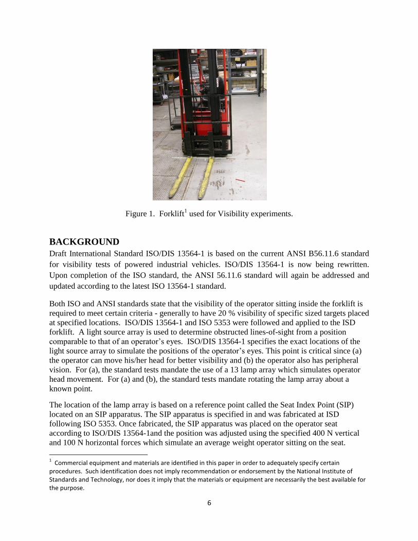
Forklift specifications are shown in Table 1 as directed in ISO/DIS 13564-1 Section 10.1 Truck
Information. This table shows the test report‟s Truck information required for visibility reports.
Table 1. Forklift Specifications
a manufacturer V.MARIOTTI b model MYCROS 8C c serial number 62,5/3339 d capacity and load centre 794 kg (1746 Lbs)
e description of lifting mechanism
lift height number of stages 2 lowered height floor reach 320 cm (126 in)
f tire information PM 267*127*65.1
g location and dimensions of truck profile in 3.2 N/A
h
location of SIP and seat information, direction of the seat (see fig 9) direction: Forward
i stand-on truck info. N/A
j
location an description of auxiliary equipment for indirect visibility N/A
EXPERIMENTAL SETUP
Apparatuses were designed and fabricated to use in the experiment according to visibility
standards. These apparatuses included the: 1) 13 lamp array; 2) test body and test screen; 3) Seat
Index Point (SIP) apparatus; 4) 100 N horizontal and 400 N vertical force application
apparatuses that applied and forces to the SIP apparatus; and 5) lamp array electronics and a

8
power supply. The test paths for eleven visibility tests, as specified in ISO/DIS 13564-1, were
also marked on the floor. Each apparatus is explained in more detail and shown in Figures 2
through 6 with the entire experimental setup shown in Figure 7. Apparatuses designed and used
are detailed here so that they can be mimicked by manufacturers, potentially saving time and
effort. The Recommendations section includes possible improvements in apparatus design and
development methods.
1. Light Source Array
Thirteen 55 W halogen lamps were used to generate light from within the forklift and were
mounted at the specified location according to ISO/DIS 13564-1. Lamps were separated by 37.5
mm and numbered according to ISO/DIS 13564-1 as in Figure 2 (b) front/end view and position
numbered as in Figure 2 (b) top view. Thirteen incandescent lamps were also initially tested and
determined to provide unclear edges and therefore, not used for standard tests. Both sets of
lights are shown in Figure 2 (a). A combination of incandescent and halogen was also tested with
little improvement. Therefore, the standard was followed using only the top row of halogen
lamps positioned as instructed in the standard. The lamp layout and numbering is shown in
Figure 2 (b).
a
13 halogen lamps
13 incandescent
lamps

9
b
Figure 2. (a) Light source arrays, including: halogen (top row) and incandescent (bottom
row); (b) Halogen lamp layout design.
2. Test Body and Test Screen
The 500 mm x 1200 mm test body and 500 mm x 1500 mm test screen (includes the test body),
as shown in Figure 3, were drawn on a white board. The test body and test screen were drawn as
specified in ISO/DIS 13564-1.
Figure 3. Test body and test screen
Test body
Test screen

10
3. Seat Index Point Apparatus
ISO 5353 details the SIP apparatus as shown in Figure 4 (a). Since the back of the SIP apparatus
was relatively complex to design and build, a modified design was used as shown in Figure 4 (b).
Computer aided designs of the differences of specified standard and the as-built SIP apparatus
used for ISD tests are shown in Appendix 1 – Modified SIP Apparatus Design. Similar contact
points are applied to the seat as in the ISO 5353 specified design since wooden blocks combined
with curved aluminum were used in the ISD design to fill the specified outside contact surface.
a
b
Figure 4. Seat Index Point Apparatus (a) as specified in ISO 5353 showing top (left drawing) and
side (right drawing) views and (b) as-built by NIST ISD.
Seat Index Point
Apparatus
11
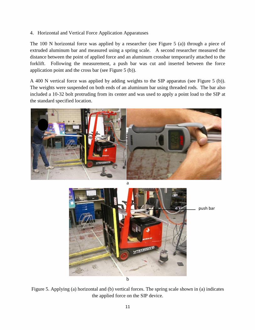
4. Horizontal and Vertical Force Application Apparatuses
The 100 N horizontal force was applied by a researcher (see Figure 5 (a)) through a piece of
extruded aluminum bar and measured using a spring scale. A second researcher measured the
distance between the point of applied force and an aluminum crossbar temporarily attached to the
forklift. Following the measurement, a push bar was cut and inserted between the force
application point and the cross bar (see Figure 5 (b)).
A 400 N vertical force was applied by adding weights to the SIP apparatus (see Figure 5 (b)).
The weights were suspended on both ends of an aluminum bar using threaded rods. The bar also
included a 10-32 bolt protruding from its center and was used to apply a point load to the SIP at
the standard specified location.
a
b
Figure 5. Applying (a) horizontal and (b) vertical forces. The spring scale shown in (a) indicates
the applied force on the SIP device.
push bar

12
5. Electrical Circuits and Power Supply
A lamp switch box was designed and built and powered by a 55 Amp power supply as shown in
Figure 6 (a). The lamp switch configuration was designed as in ISO/DIS 13564-1 to turn on
only the specified lamps. Four circuit breakers were used as switches to power various
combinations of lights as shown in the schematic in Figure 6 (b).
a
b
Figure 6. (a) Electrical setup: (left) power supply and (right) lamps switch box; (b) Lamps wiring
diagram.
13
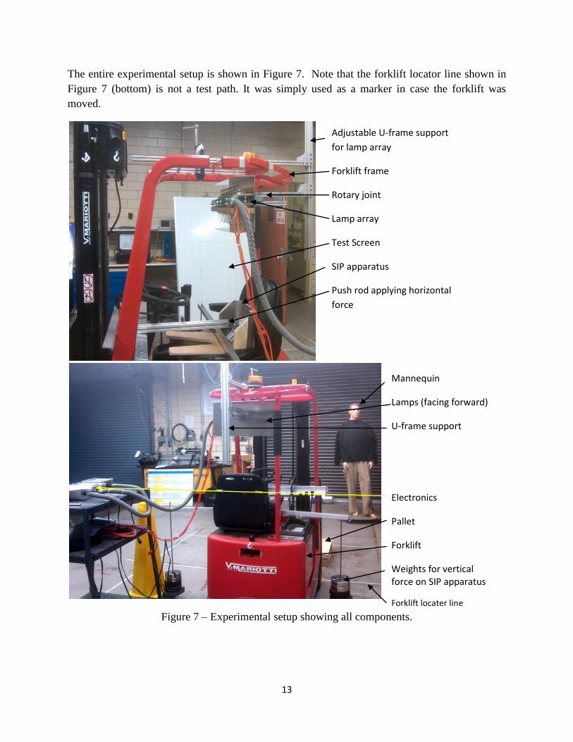
The entire experimental setup is shown in Figure 7. Note that the forklift locator line shown in
Figure 7 (bottom) is not a test path. It was simply used as a marker in case the forklift was
moved.
Figure 7 – Experimental setup showing all components.
Adjustable U-frame support
for lamp array
Forklift frame
Rotary joint
Lamp array
Test Screen
SIP apparatus
Push rod applying horizontal
force
Mannequin
Lamps (facing forward)
U-frame support
Electronics
Pallet
Forklift
Weights for vertical force on SIP apparatus
Forklift locater line
14
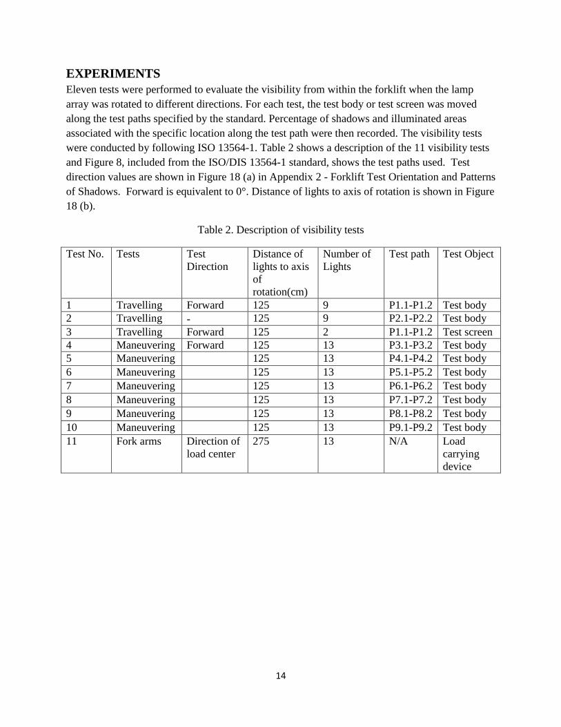
EXPERIMENTS
Eleven tests were performed to evaluate the visibility from within the forklift when the lamp
array was rotated to different directions. For each test, the test body or test screen was moved
along the test paths specified by the standard. Percentage of shadows and illuminated areas
associated with the specific location along the test path were then recorded. The visibility tests
were conducted by following ISO 13564-1. Table 2 shows a description of the 11 visibility tests
and Figure 8, included from the ISO/DIS 13564-1 standard, shows the test paths used. Test
direction values are shown in Figure 18 (a) in Appendix 2 - Forklift Test Orientation and Patterns
of Shadows. Forward is equivalent to 0°. Distance of lights to axis of rotation is shown in Figure
18 (b).
Table 2. Description of visibility tests
Test No. Tests Test
Direction
Distance of
lights to axis
of
rotation(cm)
Number of
Lights
Test path Test Object
1 Travelling Forward 125 9 P1.1-P1.2 Test body
2 Travelling - 125 9 P2.1-P2.2 Test body
3 Travelling Forward 125 2 P1.1-P1.2 Test screen
4 Maneuvering Forward 125 13 P3.1-P3.2 Test body
5 Maneuvering 125 13 P4.1-P4.2 Test body
6 Maneuvering 125 13 P5.1-P5.2 Test body
7 Maneuvering 125 13 P6.1-P6.2 Test body
8 Maneuvering 125 13 P7.1-P7.2 Test body
9 Maneuvering 125 13 P8.1-P8.2 Test body
10 Maneuvering 125 13 P9.1-P9.2 Test body
11 Fork arms Direction of
load center
275 13 N/A Load
carrying
device

15
Figure 8. Tests Path (excerpt from ISO/DIS 13564-1 FIG 7, P. 16).
16
NIST researchers performed additional experiments beyond the tests specified in ISO/DIS
13564-1, including:
1. Use of incandescent lamps instead of halogen lamps
Reason: ISO/DIS 13564-1 states the use of 13 x 55W (12 V) lamps totaling 715W when
all lamps are on. Because the lamps are 12 V powered, a power supply of nearly 60 A is
required to meet this criteria. Incandescent lamps are 120 V (in the US) x 60 W
(standard) each. They can use typical alternating current power at 0.5 A each or 7.5 A for
all 13 lamps with no additional power supply required.
2. Use of 13 incandescent and 2 halogen lamps
Reason: As in 1 above, power is the main issue. However, incandescent lamps do not
produce clear shadow edges from vehicle obstructions as do halogen bulbs. The
combination was therefore tested.
3. Use of loads carried by the forklift
Reason: the forklift is frequently loaded. Forklift operators must be able to use the
forklift during these times, too, and have appropriate visibility to control the vehicle
safely. Therefore, tests were completed using underslung and palletized loads.
Added to this test was the use of more human-type test bodies instead of a screen.
Reason: Since one main concern with operator visibility is to see pedestrians when
carrying loads, standard test pieces specified in ANSI B56.5 and a mannequin were used.
ANSI B56.5 test pieces simulate a person‟s lower leg when standing (70 mm diameter x
400 mm high) and a person‟s torso when they have fallen down (200 mm diameter x 600
mm long). The mannequin was 1.8 m high. For these tests, NIST researchers set
questions to be addressed as: Can the test pieces be seen? For the mannequin, which
body part(s) can or cannot be seen?
The results of the additional experiments are summarized in the Results of Additional
Experiments section.
EXPERIMENTAL RESULTS Most of the tests results for the forklift used met the criteria specified by the ISO/DIS 13564-1
standard which requires that the percentage of area illuminated by at least one light be at least
20 %. For those results that met the criteria, the percentage of illuminated area was very high,
around 100 % as shown in Table 3. This was because 9 or all 13 lamps, depending on the test,
were turned on simultaneously to simulate the range of positions of an operator‟s eyes from head
movement. However, this simulation was not very accurate because although the two eyes of an

17
operator could actually reach any position within the width of the lamp array, the operator‟s eyes
cannot reach all the positions at the same time.
For example, in test 1, nine lamps were turned on according to the standard. Illuminated areas
were 100 % as shown in Figure 9 (a). However, with just two lamps (No. 9 and No. 11) turned
on, the percentage of illuminated area dropped to 0 % as shown in Figure 9 (b). Therefore, there
was a blind spot with the two eyes at locations of lamps 9 and 11. Since the percentage of
illuminated area was almost 100 % for all the standard tests and the test results did not show the
existence of blind spots, the simulation was not accurate, although the results meet the criteria of
the existing standard.
a b
Figure 9. (a) Shadows of test1, (b) Shadow of test 1 with just two lamps separated by 75 mm
turned on
Test results directed by ISO 13564-1 include these points:
1) There were no auxiliary equipment used in the tests
2) For test 3, the lamps used were No. 3 and No. 5
3) For test 11, distance between lamps axis and axis of lamps rotation was 275 mm.
4) Height of load carrying surface for test 11 was 200 mm; height of load carrying surface
was 0 for all other tests.
5) Number of lamps that were not used in 5.13 was none.
Tables 3 and 4 include test results for traveling mode and maneuvering mode, respectively, and
include the following rows:
a: test number
b: percentage of illuminated area for all dark shadows

18
c: position of test body on the test path or location of dark shadow on the screen – test positions
are with respect to Figure 8 - Tests Paths as excerpt from ISO/DIS 13564-1 FIG 7, P. 16.
The percentage shown in each column under each test is with respect to row c test body and test
path position. For example, under Test 1, the percentage is 100 % illumination with the left edge
of the test screen at position P1.1.
Table 3. Test results for traveling mode of forklift
a) test number
b) percentage of illuminated area for all dark shadows
c) position of test body on the test path or location of dark shadow on the screen
Test 1 100 % left edge of screen at P1.1
100 % center of screen at longitudinal axis of forklift
100 % right edge of screen at P 1.2
Test 2 100 % right edge of screen at P2.1
100 % center of screen at midpoint of P2.1 and P2.2
100 % left edge of screen at P2.2
Test 3 100 % left edge of screen at P1.1
100 % center of screen at longitudinal axis of forklift
100 % right edge of screen at P 1.2
100 % right edge of screen at P3.1
100 % left edge of screen at 60 mm to the right of P3.1
95 % left edge of screen at P2.2
Table 4. Test results for maneuvering mode of forklift
a) test number
b) percentage of illuminated area for all dark shadows
c) position of test body on the test path or location of dark shadow on the screen
Test 4 100 % right edge of screen at P3.1
100 % left edge of screen at 60 mm to the right of P3.1
95 % left edge of screen at P2.2
90 % left edge of screen at 120 mm to the right of P3.1
91.5 % center of screen at the longitudinal axis of forklift

19
97 % right edge of screen at 120 mm to the left of P3.2
100 % right edge of screen at P3.2
Test 5 100 % left edge of screen at P4.1
100 % center of screen at 70 mm away from P4.1
100 % center of screen at 140mm away from P4.1
100 % center of screen at 210 mm away from P4.1
100 % right edge of screen at P4.2
Test 6 100 % left end point of screen at P5.1
100 % midpoint of screen at midpoint of P5.1-P5.2
100 % right end point of screen at P5.2
Test 7 100 % left end point of screen at P6.1
100 % midpoint of screen at midpoint of path P6.1-P6.2
100 % right end point of screen at P 6.2
Test 8 100 % right end point of screen at P7.2
100 % midpoint of screen at midpoint of P7.1-P7.2
100 % left end point of screen at P7.1
Test 9 100 % right end point of screen at P 8.2
100 % midpoint of screen at midpoint of P8.1-P8.2
100 % left end point of screen at P 8.1
Test 10 100 % right end point of screen at P9.2
100 % midpoint of screen at 70mm away from P9.2
100 % midpoint of screen at 140mm away from P9.2
100 % midpoint of screen at 70mm away from P9.1
100 % left end point of screen at P9.1
Test 11 50 % Forklift tines
RESULTS OF ADDITIONAL EXPERIMENTS Additional tests beyond ISO/DIS 13564-1 tests were completed by NIST researchers. Each of
the tests results are explained below.
1. Use of incandescent lamps instead of halogen lamps

20
Incandescent lamps resulted in unclear lines on the test body where percentage of shadows
could not be determined. Therefore, no results are shown for this additional test.
2. Use of 13 incandescent and 2 halogen lamps
The two halogen lamps provided additional clarity over the use of only incandescent lamps.
However, there was no additional information that could be clearly determined without
complex experimental data from the lights being use at all 13 locations. Therefore, no results
are shown for this additional test.
3. Use of loads carried by the forklift – tested on human-type test bodies instead of a screen.
Tests 1, 3, and 4 from ISO/DIS 13564-1 were completed for loads carried by a forklift.
Table 5 shows the results.
Table 5. Test results with forklift carrying a pallet of boxes. Fork arms height 90 cm, tests with
four boxes, each 31 cm3. Tests 1, 3, 4 are in the forward direction. Tests in other directions were
not affected by the pallet of boxes. See examples in Figure 10.
Test object Mannequin
1.8 m high
Standard
Test Number
1 3 4
Test Results Only head could be
seen
Only head could be seen Only head could be seen at
midpoint of path
Test object ANSI B56.5 Standard Test pieces
(200 mm dia. x 600 mm long and 70 mm dia. x 400 mm high)
Standard
Test Number
1 3 4
Test Results Could not be seen at
locations 2 and 3
Could not be seen Could be seen

21
Test object Standard Test body
Standard
Test Number
1 3 4
Test Results
comparied
to standard
tests.
Percentage of
illuminated area
dropped from 100 %
to 21 %
Percentage of illuminated
area dropped from 100% to
21 %
Illuminated area dropped to
5 % at midpoint of path and it
dropped to 50 % at location 3
along path.
Figure 10: Photos of tests with pallet of boxes (left) using the test board and (right) using a
mannequin.
Table 6. Results when fork arms were raised to 117 mm above floor. See examples in Figure 11.
Test object Mannequin
Test Number 1 3 4
Test Results Only feet and head
could be seen along
test path
Only feet and head could
be seen along test path
Head and legs could be seen
at midpoint of path. Entire
mannequin could be seen
elsewhere
22
Test object ANSI B56.5 Standard Test pieces
(200 mm dia. x 600 mm long and 70 mm dia. x 400 mm high)
Test Number 1 3 4
Test Results Could be seen Could be seen Could be seen along path
Test object Standard Test body
Test Number 1 3 4
Test Results
Compared to
standard
tests
Illuminated area
dropped from 100%
to 42% along path
Illuminated area dropped
from 100% to 42% along
path
Illuminated area dropped to
85% when test body was
located at midpoint of path,
at location 3, and at location
5, respectively.
Figure 11. Shadows on the test screen when fork arms were raised to 117 cm
23
RECOMMENDED IMPROVEMENTS TO CURRENT STANDARDS
ISO/DIS 13564-1 and ANSI/ITSDF B56.11.6
1. Change to the simulation of operator eyes.
Since turning on all the lights at the same time did not effectively simulate the positions of
two eyes of an operator, a change to the current method can be introduced and tested. Two
lamps separated by 75 mm could be used to approximate the operator‟s eye spacing. The
average human eye separation, as found in online web searches, is 65 mm. [6] Therefore, to
simulate the two eyes of an operator, only two lamps (3 and 5) were turned on. To better
simulate the movement of the head of an operator, the entire light source array was rotated
from +45° to -45°. The two shadows at the same location P1.1 were compared when
generated by the standard stationary method and the recommended rotated lamps method.
The resulting illuminated area according to the standard method was 100 %. However, the
illuminated area dropped to 0 % when the light source array was rotated to -30°. This meant
that there was a blind spot that could not be detected by the standard method and therefore,
by the operator. Figures 12 shows photos of shadows on the test screen when following the
standard and also shadows on a mannequin. Figure 13 shows the same scene after rotating
the lights -30°.
Figure 12 Shadows by following standard: (left) on a test board as specified in the standard,
(right) using a mannequin instead of the test board.

24
Figure 13. Shadows by rotating light source array -30°: (left) on the test board and (right) using a
mannequin instead of the test board.
The first suggested change of the standard is, therefore, to rotate the lamp array with only
two lamps turned on and separated 75 mm.
2. Change to test 3.
Test 3 requires turning on any two lamps separated by 75 mm. The chosen two lamps to
illuminate for tests can dramatically affect the results where a certain combination of lamps
may detect non-visible regions and the test may fail. A suggested change to the standard is
that all combinations of the lamps separated by 75 mm should be tested. Individual switches
for each light or a sliding mechanism could perhaps allow the two lamps separated by 75mm
to move as if the operators head moves side to side.
3. Include tests with underslung loads.
ISO/DIS 13564-1 mandates that the forklift be „unladen‟ (unloaded) during testing.
However, forklifts are used to carry and deliver loads. Tests were conducted with the forklift
as if carrying a battery charger as shown in Figure 14 (a). The fork arms were raised and the
fork frame structure blocked the operator‟s visibility. Three test pieces were used in the test,
including: test body, mannequin, ANSI/ITSDF B56.5 standard test pieces. When the fork
arms were raised, the percentage of illuminated area decreased as expected due to additional
forklift structure blocking lamps. When the fork arms were raised to 117 cm high,
illuminated percentage of test body dropped from 100 % shown in Figure 14 (b) to 42% as
shown in Figure 14 (c). Figure 14 (d) shows resulting shadows on a mannequin to interpret
visibility results for pedestrians and Figure 14 (e) shows similar results as in Figure 14 (c) but
on a closer test body path to the vehicle. A suggested change to the standard is that visibility
tests should be tested with the forklift carrying underslung loads.

25
a
b c
d e
Figure 14 (a) Forklift with an underslung load used for visibility tests, (b) test body before
the arms were raised, (c) test body when forklift tines were raised and resulting shadows: (d)
on a mannequin and (e) on the test body at a closer path to the fork tines.

26
4. Include tests with palletized (on-fork tine) loads.
Similar to recommendation 3, recommendation 4 suggests visibility tests also be conducted
while the forklift carries loads above the fork tines (see Figure 15 (a)), such as a pallet of
chosen standard-size boxes. Specific load size should be specified. Illuminated area was 0 %
with the test body at P1.2 as shown in Figure 15 (b). Other visibility test apparatuses were
also used in NIST tests including a mannequin and ANSI/ITSDF B56.5 standard test pieces
(see Figure 15 (c, d)). Illuminated area was 0 % with the mannequin and 0 % with the test
pieces when they were located at the midpoint of P3.1 - P3.2.
a b
c d
Figure 15. (a) Forklift carrying a pallet of boxes for visibility tests with resulting shadows shown
on: (b) the test body, (c) ANSI/ITSDF B56.5 standard test pieces, and (d) a mannequin.
5. Include tests with a smaller screen.
As in recommendation 4, ANSI/ITSDF B56.5 standard test pieces can go undetected in
certain cases. These pieces can represent a person‟s lower leg and the midsection or thigh of
a person lying in the vehicle path. Therefore, a suggested recommendation to visibility
27
standards is to also use a smaller screen to represent small obstacles along with an
appropriately safe visibility percentage. A smaller screen with 300 mm x 1000 mm was used
in the test as shown in Figure 16 (a). With the midpoint of the screen at about 45 mm to the
right of the midpoint of P1.2 - P1.2, the illuminated area of the original screen was 20 %, but
the illuminated area of the smaller screen was 0 % where it failed the visibility test. Figure 16
(b) shows that the entire smaller screen is within the shadow thereby demonstrating 0 %
visibility.
a
b
Figure 16. (a) Standard and smaller sized test screens marked on the board; (b) large screen
passing the visibility test and the smaller screen failing the visibility test (i.e., fully within the
shadow).
Standard
test body
Smaller test
body

28
6. Specify exact locations of the test screen along test paths.
Locations of the test screen and test body are not exactly presented in the standard and
provide some ambiguity as to what the exact location should be. Tests proved that test
screen locations can vary the test results. Therefore, we recommend that the exact locations
of the test screen and test body be specified to avoid confusion and to compare exact test
results to other similar forklifts. Should locations vary with respect to the forklift size and
geometry, it is recommended that varying test screen locations with respect to the forklift be
required.
7. Inform the reader of a typical type of lamps and their mounts.
Lamps were relatively expensive ($11 each x 13), difficult to locate, and were eventually
purchased from an automobile parts store. As a result, a custom slot-type mounting plate
was designed (see Figure 2) to support the lamps due to their unique shape and spacing
requirement. The slotted lamp plate also allowed lamps to be moved as in recommendation 2
to test two lamps, spaced 75 mm apart and mounted in various slots. Therefore, it is
recommended that the standard provide information of the typical type of lamps, beyond
stating “halogen or similar,” and how to mount them in the specified array.
8. Specify the danger of using halogen lamps.
Although halogen lamps provide the ideal sharp edged shadows required by the standard,
they can be hazardous. Halogen lamps are extremely hot, extremely bright, and require
relatively high power as compared to standard incandescent light bulbs. Two
recommendations are therefore: a) to provide a safety discussion in the standard with regard
to lamp heat, luminescence, and power; b) to list the lamp luminescence in lumens, not watts,
so that potentially safe, lower power or heat lamps can be used for tests and advanced
technology in light sources can be compared to the 55 W halogen lamps currently specified.
We also suggest that further research is needed with the use of Light Emitting Diode (LED)
or other low temperature and low power lamps.
9. Include advanced visibility measurement test methods.
Minimal information is provided in visibility standards for an advanced measurement
solution for powered industrial vehicles. A proposed plan is in place at NIST to collaborate
with a university to develop test methods for the advanced visibility measurement of
powered industrial vehicles. At least one university has studied construction vehicle
visibility issues using advanced laser scanning techniques. [11] As these visibility
measurement techniques evolve for powered industrial vehicles, the standard should reflect
the usefulness of such systems and how they provide additional benefit. Benefits will
include measurement time savings, safe test methods, and more accurate and detailed
measurement and representation of non-visible regions.

29
Current efforts are being made towards ensuring complete powered industrial vehicle
operator visibility (see Appendix 3 – Recent visibility efforts) and accurate knowledge of
sensor type (e.g., 2-dimensional laser detection and ranging verses 3-dimensional light
detection and ranging) that can ensure safe vehicle operation. Hence, the non-visible regions
must be clearly represented to advanced technology providers of augmented visibility sensor
systems on, or soon to be on, the market. Current test methods described in visibility
standards provide allowable non-visibility percentages from shadows on a movable test body
creating a piecemeal model of non-visible regions. The methods may be tedious, time-
consuming, and less accurate for industrial vehicle manufacturers to design improvements
and for augmenting visibility sensor providers to determine sensor type and mounting
locations for safe 100 % operator visibility.
ISO 5353: 1995 1. Change the SIP apparatus drawings.
Separate SIP apparatus component dimensioned drawings into individual drawings and also
provide an assembly drawing with appropriate tolerances. The SIP apparatus drawing layout
specified by the standard required potentially unnecessary time and additional materials.
Drawings that interpreted the standard were additionally required to produce parts. This is
because X, Y coordinates, as used by machinists for dimension layout and computer
numerical control input, are not shown in the standard on each piece to be fabricated. See the
SIP apparatus base drawing on wood in Figure 17 (a). The outside rectangle is the overall
dimension of the SIP apparatus where several base dimensions are referenced in the standard
(see Figure 23 of Appendix 1 – Modified SIP Apparatus Design). To produce the drawing
shown within the Figure 17 (a) rectangle, either the wood must be marked or an additional
interpretation drawing is required. Other components needed for NIST to make the SIP
apparatus are shown in Figure 17 (b) and the fully assembled apparatus is shown in Figure 17
(c). Ideally, a base drawing and each other component drawing required are individually
shown in the standard with an additional assembly drawing showing mounting dimensions
and locations. A photo of a completed system may also be very useful.
Also, tolerances are shown to 0.0 mm and may not be necessary for fabrication and as such,
increase machining and assembly costs.
30
a b
c
Figure 17. (a) SIP Apparatus: (a) base drawn on a piece of wood (b) joining bar for base to back,
(c) fully assembled apparatus on a forklift seat.
SUMMARY AND CONCLUSIONS Standard tests for operator visibility when driving forklifts allow for 20 % non-visible regions.
Some safety technologies are on the market that can help to reduce pedestrian and forklift driver
injuries. However, large numbers of accidents still occur. Standard tests were performed by
NIST researchers to provide recommendations to the standard committees on better test methods
and to provide basis for future NIST industrial vehicle programs. Standard tests provided few
results that demonstrate the actual non-visible regions of forklifts. Based on the results of the
testing, there are a number of recommendations to improve these standards including: the use of

31
low power and temperature lamps; tests that allow lamp placement resembling an operators
instantaneous eye position; and use of simpler test apparatuses and advanced test methods that
use lasers that measure exact locations of non-visible regions for improving forklifts and their
safety. These advanced methods can also allow sensor and vehicle manufacturers to develop on-
board vehicle systems to improve operator alerts and semi-autonomous slow and stop controls.
Advanced 2D and 3D imaging sensors are potentially useful for onboard safety measurement of
non-visible regions. Future plans are to measure the performance of advanced laser systems used
to measure non-visible regions of forklifts and to publish results as further recommendations to
standards committees. Example measurement results of 3D imagers with operator alerts and a
laser measurement system are shown in Appendix 3 – Recent and planned visibility efforts.
ACKNOWLEDGEMENTS The authors would like to acknowledge the ANSI/ITSDF B56.11.6 committee who provided
standards information to perform the tests.
REFERENCES [1] Roger Bostelman, Will Shackleford, “Advanced Sensing Towards Improved Forklift Safety”,
PerMIS 2010 Proceedings, Gaithersburg, MD.
[2] ANSI/ITSDF, http://www.itsdf.org/pB56.asp, 2011.
[3] International Organization for Standardization, http://www.iso.org, 2011.
[4] ISO/DIS 13564-1: 2007 - Powered Industrial trucks – Visibility - Test methods and
verification-Part 1: Sit-on and stand-on operator trucks and variable reach trucks.
[5] ANSI/ITSDF B56.11.6: 20xx - Evaluation of Visibility from Powered Industrial Trucks.
[6] Bostelman, Roger, 2009. “White paper, Towards Improved Forklift Safety,” PerMIS 2009
Proceedings, Gaithersburg, MD.
[7] Measurement Science for Intelligent Manufacturing Robotics and Automation Program
website: http://www.nist.gov/el/isd/si/msimra.cfm, 2011.
[8] ANSI/ITSDF B56.5: 2010 - Safety Standard for Driverless, Automatic Guided Industrial
Vehicles and Automated Functions of Manned Industrial Vehicles.
[9] ANSI/ITSDF B56.11.6: 20xx - Evaluation of Visibility From Powered Industrial Trucks
[10] ISO 5353: 1995 - Earth-moving machinery, and tractors and machinery for agriculture and
forestry-Seat Index Point

32
[11] Wolfgang Wieser, “Creating stereoscopic left-right image pairs with POVRay,”
http://www.triplespark.net/render/stereo/create.html, September 2, 2007.
[12] Jochen Teizer, Ben S. Allread, Uday Mantripragada, “Automating the blind spot
measurement of construction equipment,” Automation in Construction Journal, Vol. 19 (2010),
pp. 491–501.

33
APPENDICES
Appendix 1 - Modified SIP Apparatus Design
green outlined parts = NIST machined part adapted to ISO standard – green part
is 6.4 mm (1/4 in) thick aluminum with wooden blocks added to match standard
dimensions.
Figure 18. SIP Apparatus drawing showing standard drawing in gray and red, black and green
modifications for NIST experiments.

34
Appendix 2 - Forklift Test Orientation and Patterns of Shadows
a b
c d
Figure 19. (a) Top view of lamps test angles as specified by ISO/DIS 13564-1, (b) Lamps rotary
joint, (c) Lamps facing forward, (d) Lamps facing to the rear of the forklift.
Distance of lights to
axis of rotation
Lamps
Axis of lamp array
rotation
0°

35
a
b c
Figure 20. Examples of shadows of visibility tests, from: (a)Test 3, at location 3, (b) test 4,
location 3, and (c) test 3, location is left edge of test screen at P1.1.

36
Appendix 3 - Recent and planned visibility efforts • Performance testing of advanced 3D imagers on test pieces
• Performance measurement of advanced 3D imagers mounted to forklifts to detect obstacles,
pedestrians in the NIST lab and in a real manufacturing facility
• Development of software to integrate 3D imaging with operator alerts (see Figure 20)
• Georgia Institute of Technology has focused advanced visibility measurements on
construction vehicle visibility (see Figure 21) [11]. NIST is planning to work with a
university on advanced visibility measurements for powered industrial vehicles.
a b
c
Figure 21. 3D imagers mounted on a forklift and integrated with simple operator alerts – (a)
obstacle is behind the forklift and (b) the alert indicates the obstacle, (c) high lift obstacle detect
sensor mounted to forks frame (upper right photo) capturing data of ceiling joists (lower left).
Ceiling joist being detected
37
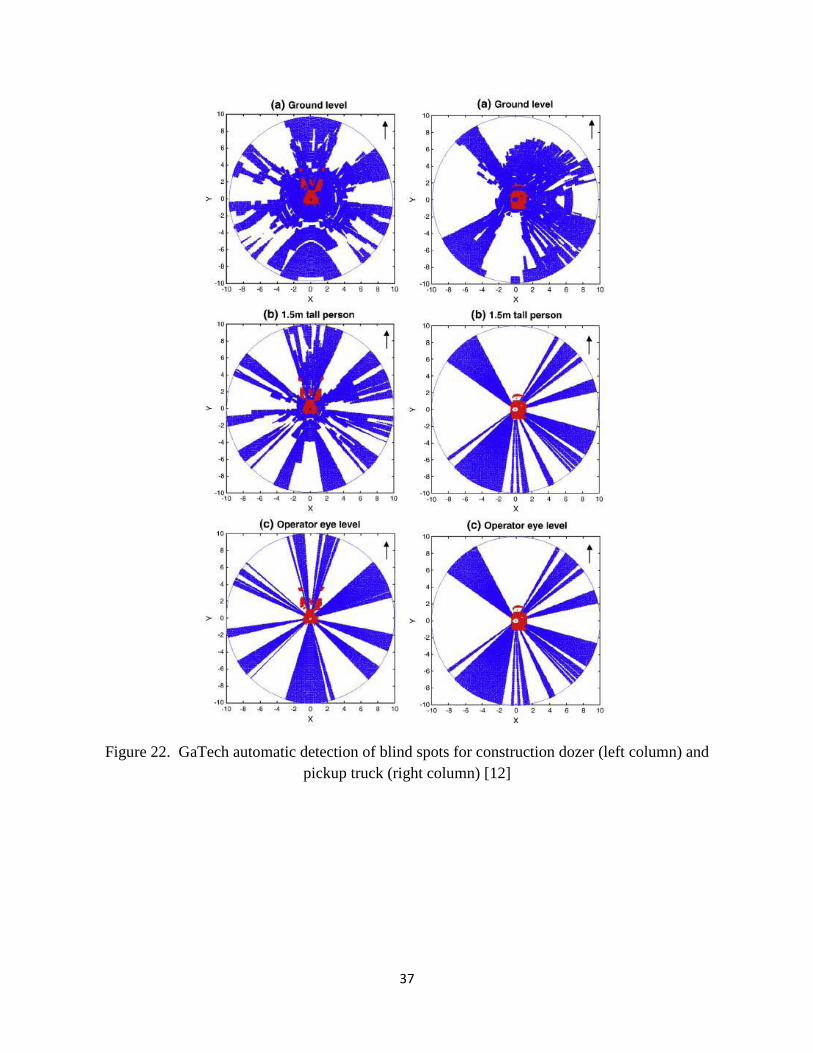
Figure 22. GaTech automatic detection of blind spots for construction dozer (left column) and
pickup truck (right column) [12]