Embed Size (px)
Citation preview

Measuring IP NetworkRouting Convergence
A new approach to theproblem
59
2
A Blind Spot In NetworkPerformance Monitoring
Today’s monitoring technologies tell us how thenetwork performs in steady state
It does not tell us how quickly it becomes usableafter a failure
Conventional monitoring will treatmeasurements of a network undergoing randomrouting changes as strange outliers
To properly measure network response,changes they have to introduced in a controlledmanner.
3
Network Convergence Is Hard ToMeasure in Production
Have you measured the convergence speed ofyour network? How often do you do it?
The obvious way to do this is to measure trafficloss when you induce a network failure
Measuring network convergence is serviceimpacting and a manual process
What if you could measure network convergencewithout service impact?
What if you could automate it?
4
An Enabling Technology Two Way Jitter Measurement Probes
A sending device (sender) transmits a stream ofnumbered packets with a fixed packet interval toa responding device
The responding device (responder) returns thepackets back to the sender
The sender reports on latency, jitter and packetloss
Examples
RFC5357 TWAMP, RFC6812 Cisco’s Service-Level Assurance Protocol. Other proprietaryvendor probe protocols exist
5
A new approach
Induce controlled change using routing protocolsand observe the impact on active jitter probes tomeasure network convergence (protocolconvergence & FIB insertion) across all routersin a network
The technique is not service impacting and canbe performed periodically to baseline and tracknetwork performance

6
How it works
A probe sender participates in a network routingprotocol
7
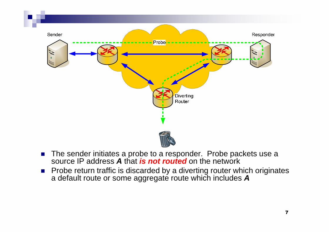
The sender initiates a probe to a responder. Probe packets use asource IP address A that is not routed on the network
Probe return traffic is discarded by a diverting router which originatesa default route or some aggregate route which includes A

8
While the probe is running, at some time t0 thesender announces a route for A into the network
9
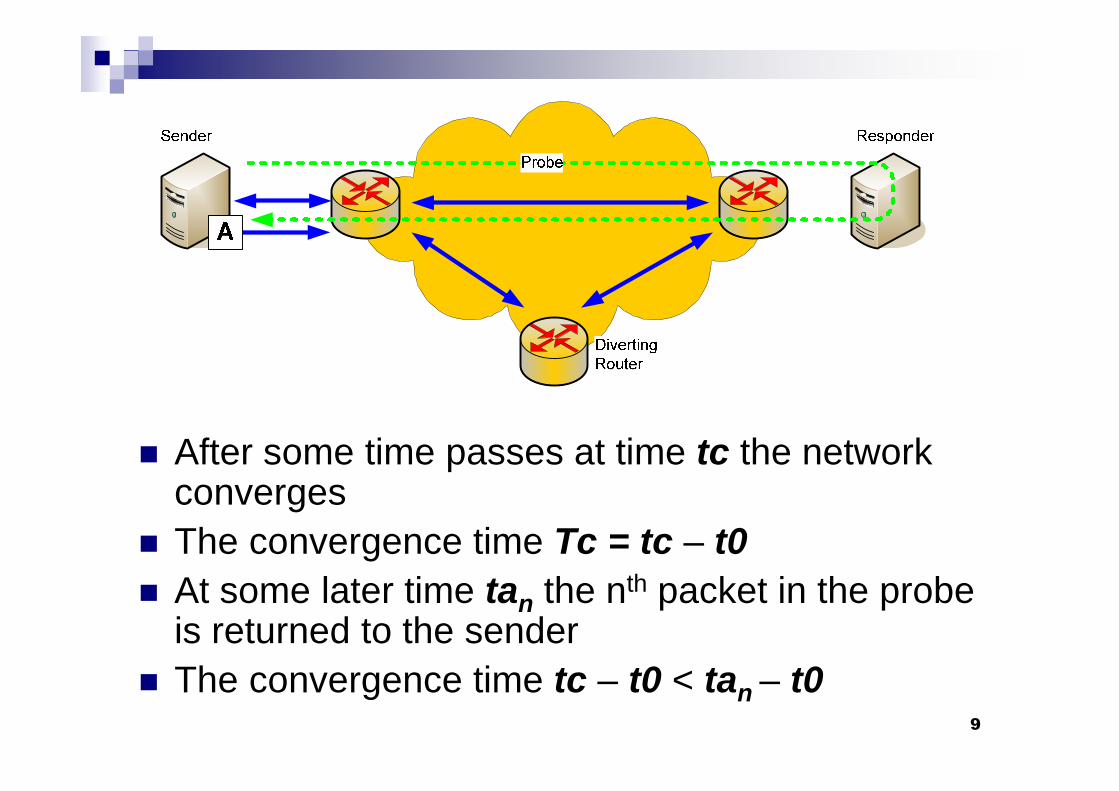
After some time passes at time tc the networkconverges
The convergence time Tc = tc – t0
At some later time tan the nth packet in the probeis returned to the sender
The convergence time tc – t0 < tan – t0
10
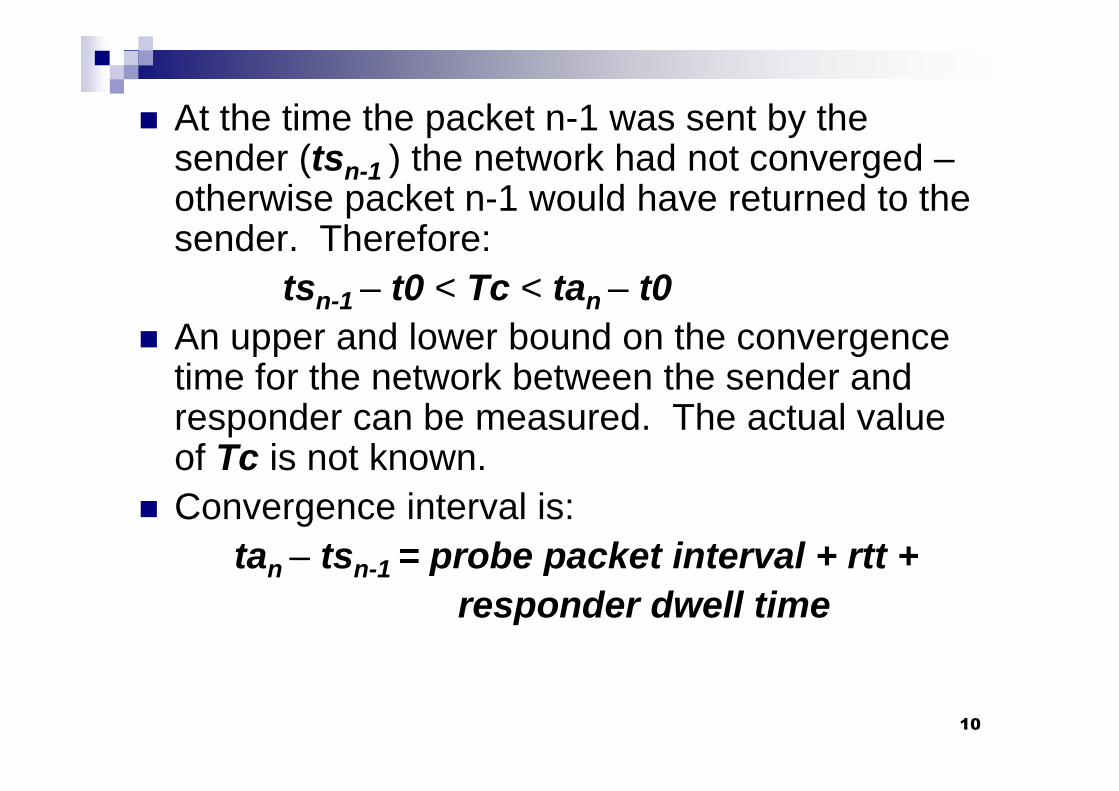
At the time the packet n-1 was sent by thesender (tsn-1 ) the network had not converged –otherwise packet n-1 would have returned to thesender. Therefore:
tsn-1 – t0 < Tc < tan – t0
An upper and lower bound on the convergencetime for the network between the sender andresponder can be measured. The actual valueof Tc is not known.
Convergence interval is:
tan – tsn-1 = probe packet interval + rtt +
responder dwell time
11
The technique can be applied to any routingprotocol or combinations of protocols and isequally applicable to IPv4 and IPv6
Sender clock does not have to be synchronizedwith any other device
Convergence of multiple paths across thenetwork can be measured by launchingsimultaneous probes to different responders
Because it can run continuously the effect oftime-of-day, day-of-week, and transient flash-mob effects on routing can be observed
12
MPLS Networks
Convergence time of protocols running in VRFsconnected to an MPLS VPN can be measured
By measuring the IGP convergence time of BGPnexthops in an MPLS network IGP+LDPconvergence can be measured
13
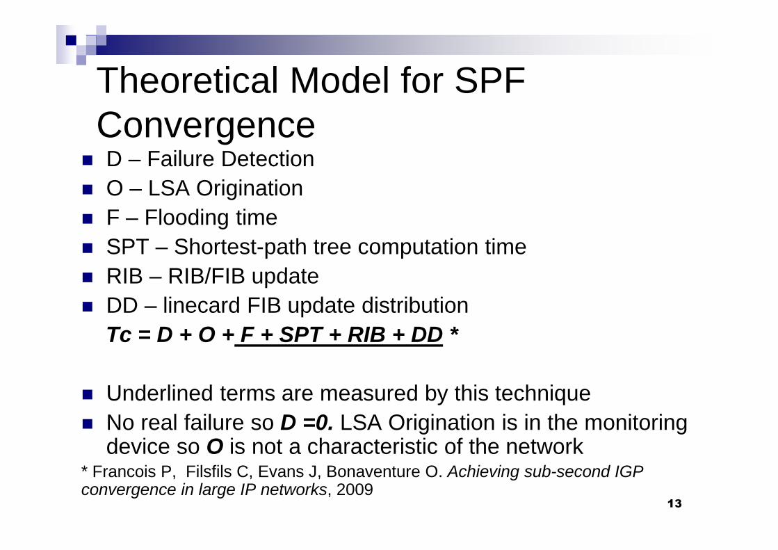
Theoretical Model for SPFConvergence
D – Failure Detection
O – LSA Origination
F – Flooding time
SPT – Shortest-path tree computation time
RIB – RIB/FIB update
DD – linecard FIB update distribution
Tc = D + O + F + SPT + RIB + DD *
Underlined terms are measured by this technique
No real failure so D =0. LSA Origination is in the monitoringdevice so O is not a characteristic of the network
* Francois P, Filsfils C, Evans J, Bonaventure O. Achieving sub-second IGPconvergence in large IP networks, 2009
14
Why this is useful Network qualification Confirm SLA compliance Baselining and tracking convergence allows
changes in network performance to be detected Network architecture validation (before and after
testing) Troubleshooting network & routing performance
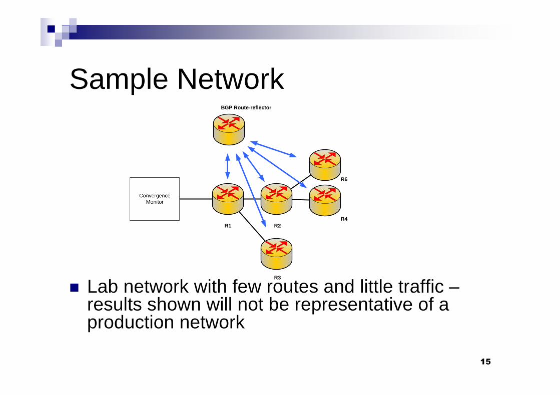
Sample Network
15
Lab network with few routes and little traffic –results shown will not be representative of aproduction network
ConvergenceMonitor
R1 R2
R3
R4
R6
BGP Route-reflector
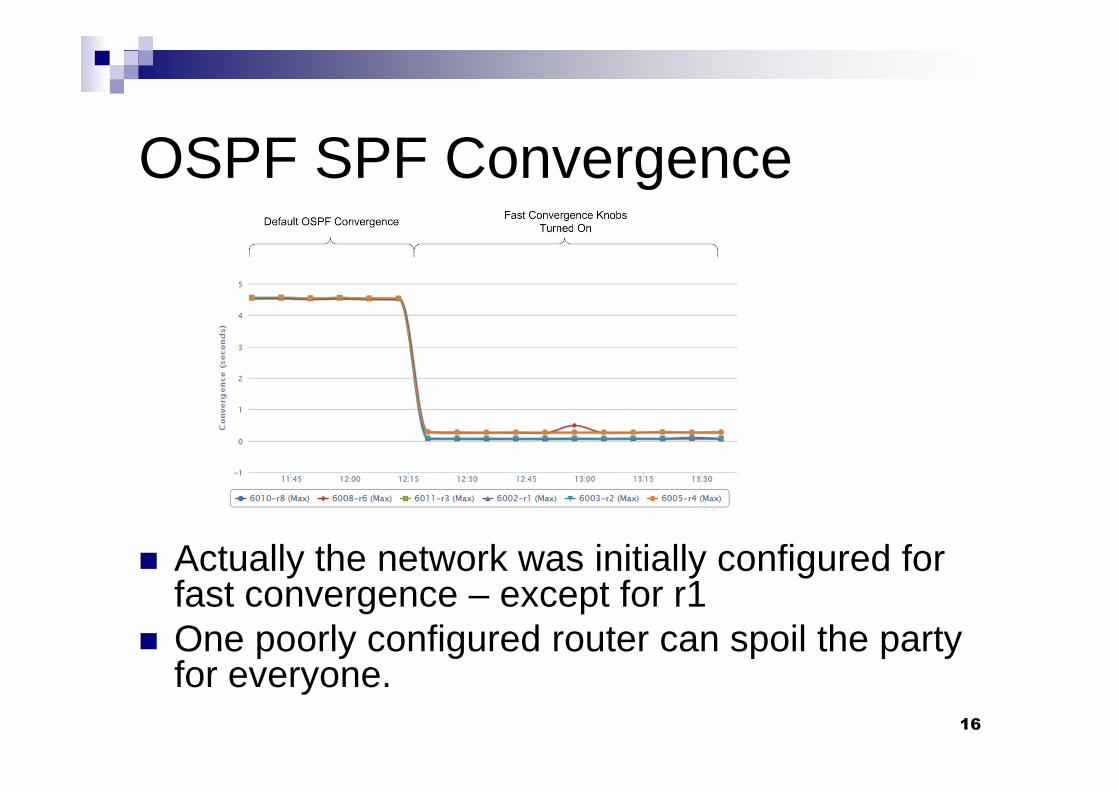
OSPF SPF Convergence
16
Actually the network was initially configured forfast convergence – except for r1
One poorly configured router can spoil the partyfor everyone.
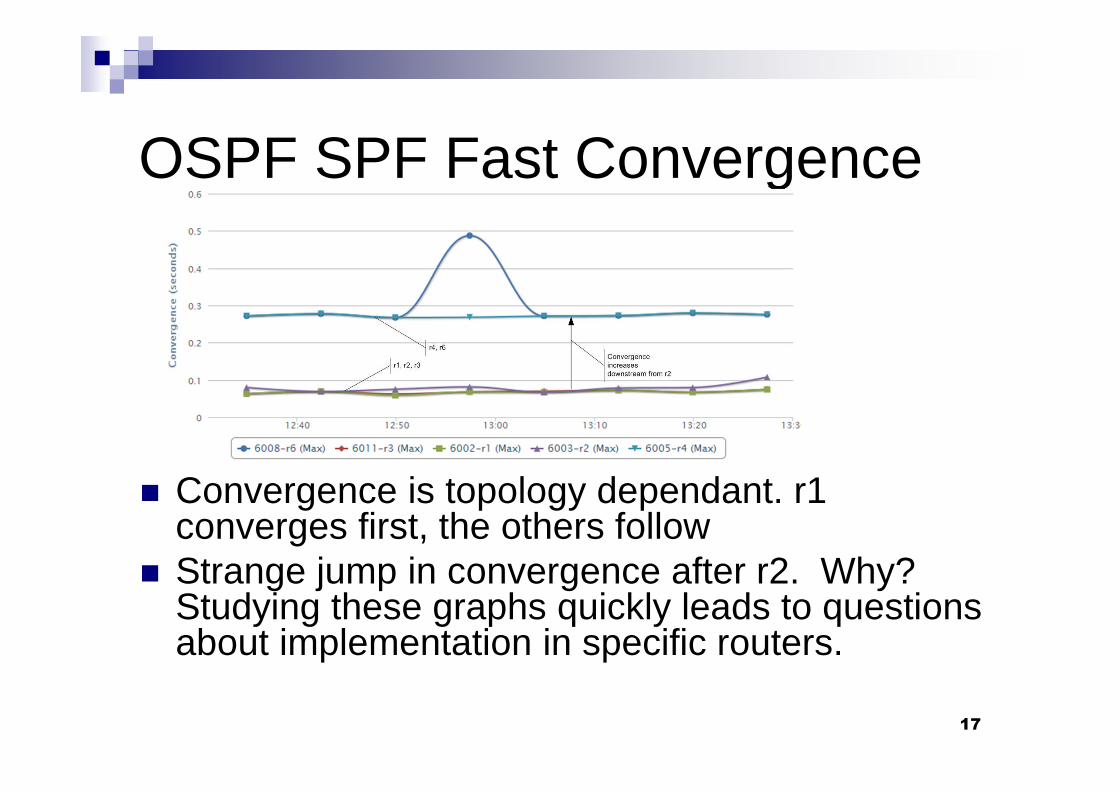
OSPF SPF Fast Convergence
17
Convergence is topology dependant. r1converges first, the others follow
Strange jump in convergence after r2. Why?Studying these graphs quickly leads to questionsabout implementation in specific routers.
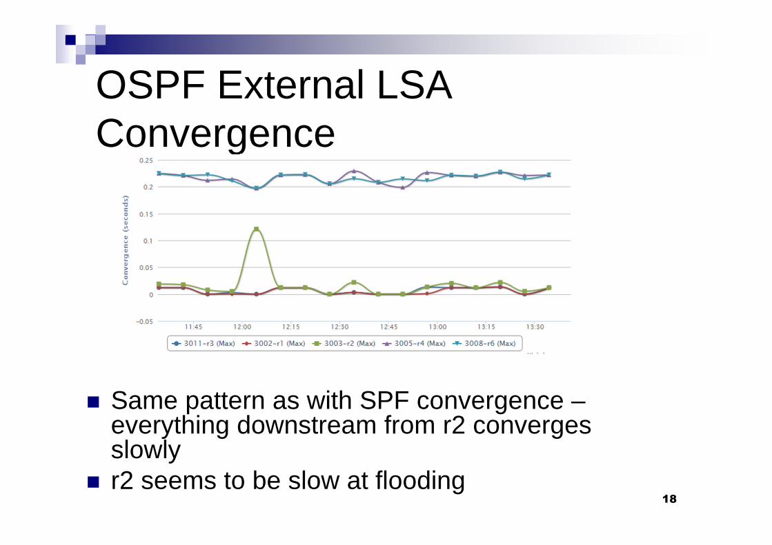
OSPF External LSAConvergence
18
Same pattern as with SPF convergence –everything downstream from r2 convergesslowly
r2 seems to be slow at flooding

BGP Convergence
19
BGP is very fast on this small network r2 seems to converge more slowly than r4 and
r6. This is actually an indicator that it is slow inprocessing IP SLA packets. Cisco recommendsthe use of shadow routers as IP SLA responders

20
Thank You
For further information please contact
Laris Benkis
(613) 261 8052
http://www.tpn.cc