Embed Size (px)
Citation preview
Measuring of damper characteristics
Ing. Aleš Bílkovský Abstract (in Czech) Cílem projektu Měření charakteristik tlumičů v rámci Nadace ČVUT Media Lab je změření sady tlumičů a porovnání jejich statických charakteristik a nalezení korelace mezi objektivním a subjektivním hodnocením výsledných vlastností vozidla. Keywords Shock absorber, identification of shock absorber, damper characteristic
1. Introduction Nowdays, the shock absorbers are used at two places. The main place is axle of the vehicle. The second place is the damped driver’s seat. The suspension setting and vehicle damping have to realize two requirements. The first requirement is dissipation of energy, damping of crashes that are realized by vehicle on the rough road and the transfer restriction of vibration chassis to the crew comfort. The second requirement is oscillating termination of unsprung bodies to realized continuing contact between wheel and road so that the driving, breaking and side forces can be realized. The basic characterization of the shock absorber is the nonlinear force – velocity dependence. But the shock absorber has an important hysteretic behaviour. The summary comfort valuation of vehicle are used the test drivers. They are able to compare the vibration and the shock absorber in the vehicle. But their valuation is subjective. These drivers are able to compare the shock absorber in the vehicle. They are able to find small difference between two shock absorbers with the same basic force - velocity characteristic. Drivers compare the shock absorbers for all of type’s chassis and motors and choose the fit shock absorber. Main goal of the project is an objective comparison of several shock absorbers and an ability of damper differentiates with the same basic force - velocity characteristic.
2. Dampers Shock absorbers must absorb or dissipate energy. Hydraulic shock absorbers commonly take the form of a cylinder with a sliding piston inside. The cylinder is filled with a hydraulic fluid or air. The shock absorber consists of an internal and external cylinder. In the internal cylinder, also referred to as the pressure tube, a piston assembly fixed at the lower end of piston rod can move up (rebound) and down (compression). The space in the internal cylinder above the piston is called the rebound chamber while the space below the piston is referred to as the compression chamber. The chambers are filled with hydraulic oil. The oil is flowed from the rebound chamber to the compression chamber during other construction chambers. Movement of piston produced the resistance force [6]. Two series of hydraulic shock absorbers were obtained for the project. Each of series is made by other company, but these series are designed for the same vehicle and are with the same basic characteristic. The test drives felt the difference between the shock absorbers. The series contain six shock absorbers.
These dampers are black-box, there are not known any parameters about inner construction of damper. The outer construction proportions of the dampers were measured. The contact points were measured and compared. There were found difference. The outer diameter of piston of first series of damper is 43 mm, but the second series of damper is 45mm. The diameter of hole (access point) at the lower end of shock absorber of first series is 14mm, the diameter of second series is 14,2 mm.
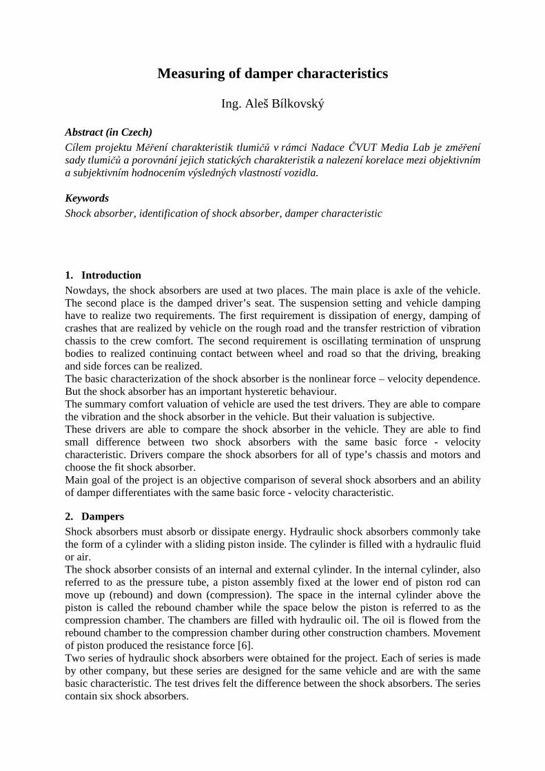
3. Measuring system The measuring system (Figure 1) is assembled from
o PC with control card by Inova Praha with control software o Experimental hydraulic machine
� Generator HU63-M06 � Moving piston (Cylinder) INOVA AH-10-250H01 � Position sensor WLG 250 0.25%
o Induction position transducer HBM WA100MM-L o Induction amplifier HBM AE501 o Force transducer HBM S9 2kN o Amplifier for SG-Transducers HBM RM4220
Figure 1 Measuring system
4. Experiments and results A shock absorber that is normally used on the rear suspension of vehicle has been tested in the stand. In the set up, the shock absorber is fixed at its lower end to the moving piston of the hydraulic shaker while the upper part is fixed to the stiff frame means of a load cell as to measure the damper force. In supplement the damper displacement is measured independently by transducer.
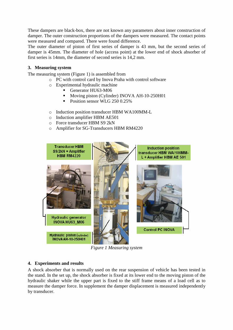
The used training signals are prepared with respects to the typical using. The used experimental signal consists on harmonic excitation with frequency from 0.1 Hz to 10 Hz with different amplitudes from 2 mm to 20 mm typical for damper working and the stochastic signal for damper on the stochastic road. The velocity and acceleration are reconstructed from the length measurement. The main working range for the damper is 2 mm. There are presented result for the measurement 2mm amplitude and frequency from 0,1 Hz to 10 Hz.
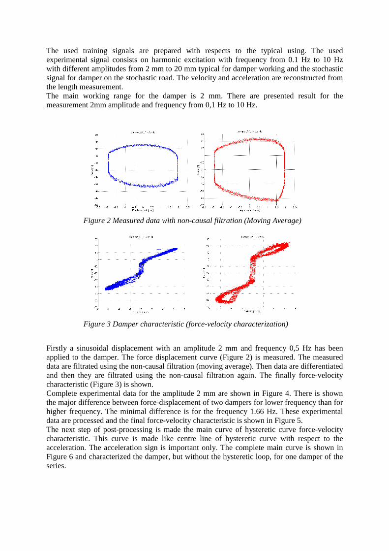
Firstly a sinusoidal displacement with an amplitude 2 mm and frequency 0,5 Hz has been applied to the damper. The force displacement curve (Figure 2) is measured. The measured data are filtrated using the non-causal filtration (moving average). Then data are differentiated and then they are filtrated using the non-causal filtration again. The finally force-velocity characteristic (Figure 3) is shown. Complete experimental data for the amplitude 2 mm are shown in Figure 4. There is shown the major difference between force-displacement of two dampers for lower frequency than for higher frequency. The minimal difference is for the frequency 1.66 Hz. These experimental data are processed and the final force-velocity characteristic is shown in Figure 5. The next step of post-processing is made the main curve of hysteretic curve force-velocity characteristic. This curve is made like centre line of hysteretic curve with respect to the acceleration. The acceleration sign is important only. The complete main curve is shown in Figure 6 and characterized the damper, but without the hysteretic loop, for one damper of the series.
Figure 2 Measured data with non-causal filtration (Moving Average)
Figure 3 Damper characteristic (force-velocity characterization)
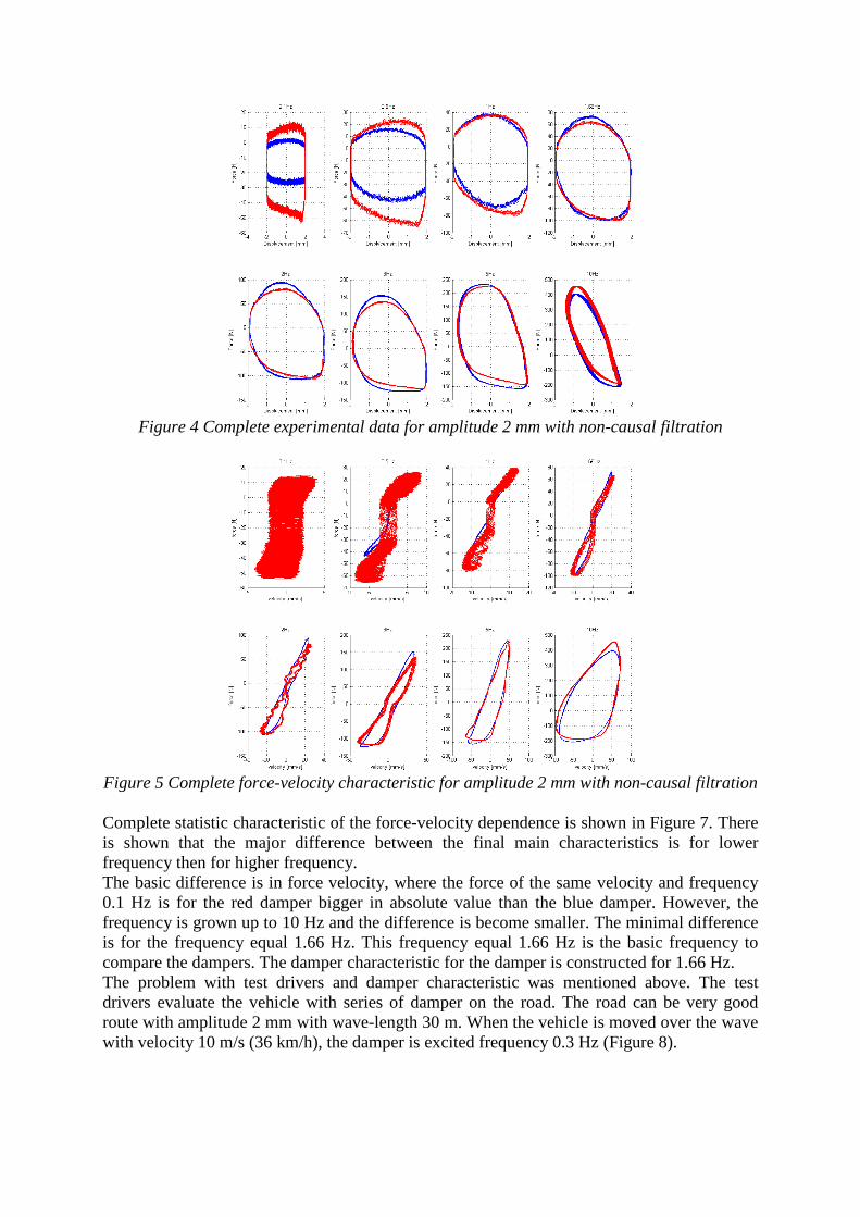
Figure 4 Complete experimental data for amplitude 2 mm with non-causal filtration
Figure 5 Complete force-velocity characteristic for amplitude 2 mm with non-causal filtration Complete statistic characteristic of the force-velocity dependence is shown in Figure 7. There is shown that the major difference between the final main characteristics is for lower frequency then for higher frequency. The basic difference is in force velocity, where the force of the same velocity and frequency 0.1 Hz is for the red damper bigger in absolute value than the blue damper. However, the frequency is grown up to 10 Hz and the difference is become smaller. The minimal difference is for the frequency equal 1.66 Hz. This frequency equal 1.66 Hz is the basic frequency to compare the dampers. The damper characteristic for the damper is constructed for 1.66 Hz. The problem with test drivers and damper characteristic was mentioned above. The test drivers evaluate the vehicle with series of damper on the road. The road can be very good route with amplitude 2 mm with wave-length 30 m. When the vehicle is moved over the wave with velocity 10 m/s (36 km/h), the damper is excited frequency 0.3 Hz (Figure 8).
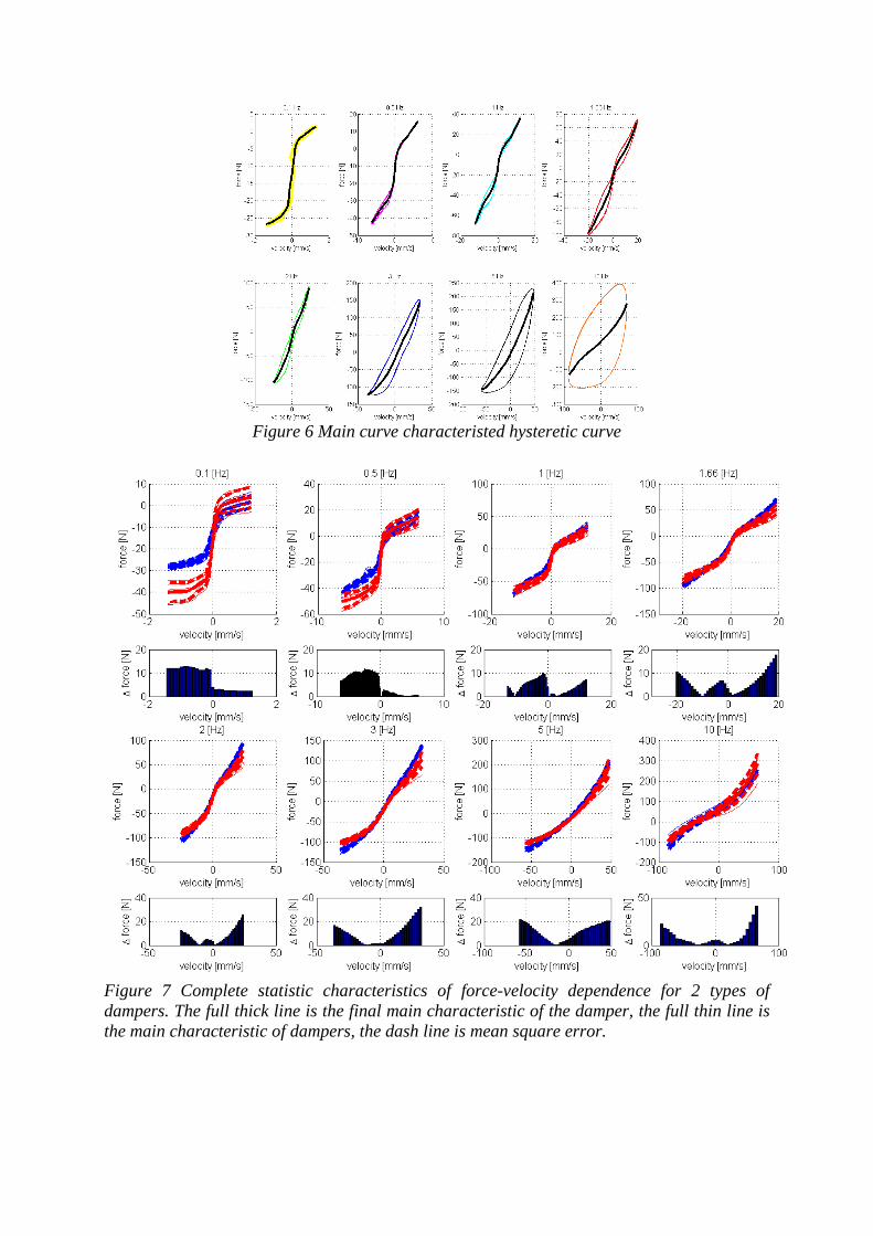
Figure 6 Main curve characteristed hysteretic curve
Figure 7 Complete statistic characteristics of force-velocity dependence for 2 types of dampers. The full thick line is the final main characteristic of the damper, the full thin line is the main characteristic of dampers, the dash line is mean square error.
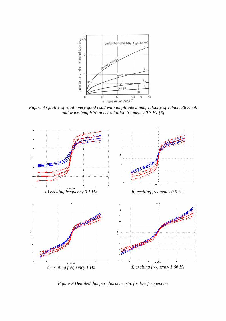
Figure 8 Quality of road - very good road with amplitude 2 mm, velocity of vehicle 36 kmph
and wave-length 30 m is excitation frequency 0.3 Hz [5]
a) exciting frequency 0.1 Hz
b) exciting frequency 0.5 Hz
c) exciting frequency 1 Hz
d) exciting frequency 1.66 Hz
Figure 9 Detailed damper characteristic for low frequencies
This exciting frequency 0.3 Hz is between the frequencies 0.1 Hz and 0.5 Hz. The measured and processed data for frequencies 0.1 Hz to 1.66 Hz are presented in Figure 9. However, the difference fall and the dampers become the same like is shown in Figure 9 d).
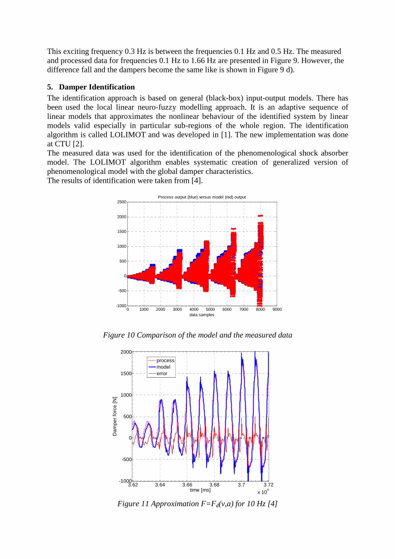
5. Damper Identification The identification approach is based on general (black-box) input-output models. There has been used the local linear neuro-fuzzy modelling approach. It is an adaptive sequence of linear models that approximates the nonlinear behaviour of the identified system by linear models valid especially in particular sub-regions of the whole region. The identification algorithm is called LOLIMOT and was developed in [1]. The new implementation was done at CTU [2]. The measured data was used for the identification of the phenomenological shock absorber model. The LOLIMOT algorithm enables systematic creation of generalized version of phenomenological model with the global damper characteristics. The results of identification were taken from [4].
0 1000 2000 3000 4000 5000 6000 7000 8000 9000-1000
-500
0
500
1000
1500
2000
2500
data samples
Process output (blue) versus model (red) output
Figure 10 Comparison of the model and the measured data
3.62 3.64 3.66 3.68 3.7 3.72
x 104
-1000
-500
0
500
1000
1500
2000
time [ms]
Dam
per
forc
e [N
]
processmodelerror
Figure 11 Approximation F=Fd(v,a) for 10 Hz [4]
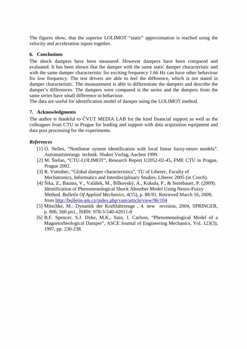
The figures show, that the superior LOLIMOT “static” approximation is reached using the velocity and acceleration inputs together.
6. Conclusions The shock dampers have been measured. However dampers have been compared and evaluated. It has been shown that the damper with the same static damper characteristic and with the same damper characteristic for exciting frequency 1.66 Hz can have other behaviour for low frequency. The test drivers are able to feel the difference, which is not stated in damper characteristic. The measurement is able to differentiate the dampers and describe the damper’s differences. The dampers were compared is the series and the dampers from the same series have small difference in behaviour. The data are useful for identification model of damper using the LOLIMOT method.
7. Acknowledgments The author is thankful to ČVUT MEDIA LAB for the kind financial support as well as the colleagues from CTU in Prague for leading and support with data acquisition equipment and data post processing for the experiments. References
[1] O. Nelles, “Nonlinear system identification with local linear fuzzy-neuro models”. Automatisierungs technik. Shaker Verlag, Aachen 1999.
[2] M. Štefan, “CTU-LOLIMOT”, Research Report U2052-02-45, FME CTU in Prague, Prague 2002.
[3] R. Votrubec, “Global damper characteristics”, TU of Liberec, Faculty of Mechatronics, Informatics and Interdisciplinary Studies, Liberec 2005 (in Czech).
[4] Šika, Z., Bauma, V., Valášek, M., Bílkovský, A., Kukula, P., & Steinbauer, P. (2009). Identification of Phenomenological Shock Absorber Model Using Neuro-Fuzzy Method. Bulletin Of Applied Mechanics, 4(15), p. 88-91. Retrieved March 16, 2009, from http://bulletin-am.cz/index.php/vam/article/view/96/104
[5] Mitschke, M.: Dynamik der Kraftfahrzeuge , 4. new revision, 2004, SPRINGER, p. 806, 560 pict., ISBN: 978-3-540-42011-8
[6] B.F. Spencer, S.J. Dyke, M.K., Sain, J. Carlson, “Phenomenological Model of a Magnetorheological Damper”, ASCE Journal of Engineering Mechanics, Vol. 123(3), 1997, pp. 230-238.


![ACATacat.or.th/download/acat_or_th/journal-4/04 - 04.pdf · APmin APmax Appendix G [1] AP APmax Overpressure Relief Damper Damper 12 Relief Damper Relief Damper (Vent) Fire Damper](https://img.pdfslide.net/doc/110x75/5f7cb481641db55595223717/-04pdf-apmin-apmax-appendix-g-1-ap-apmax-overpressure-relief-damper-damper.jpg)