Embed Size (px)
Citation preview
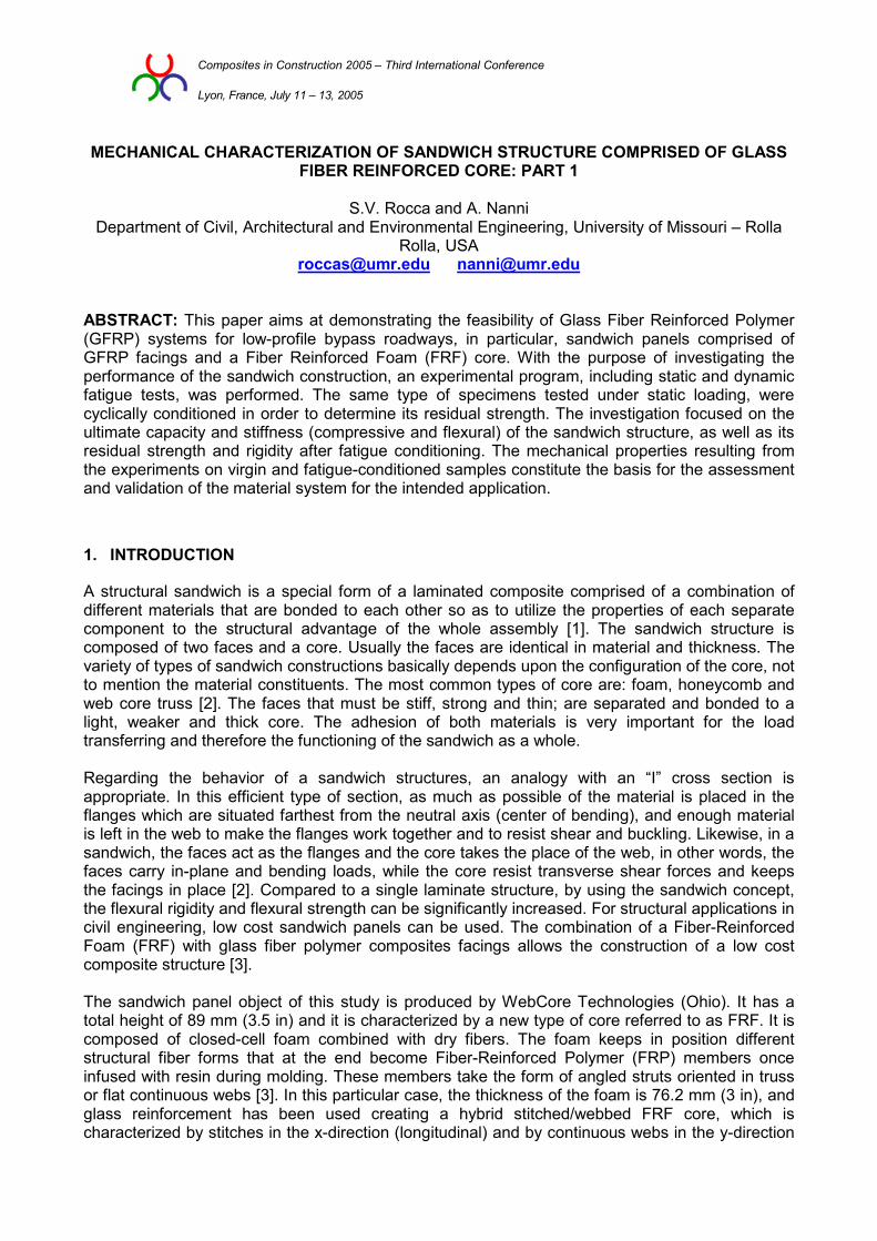
Composites in Construction 2005 – Third International Conference Lyon, France, July 11 – 13, 2005
MECHANICAL CHARACTERIZATION OF SANDWICH STRUCTURE COMPRISED OF GLASS FIBER REINFORCED CORE: PART 1
S.V. Rocca and A. Nanni
Department of Civil, Architectural and Environmental Engineering, University of Missouri – Rolla Rolla, USA
[email protected] [email protected]
ABSTRACT: This paper aims at demonstrating the feasibility of Glass Fiber Reinforced Polymer (GFRP) systems for low-profile bypass roadways, in particular, sandwich panels comprised of GFRP facings and a Fiber Reinforced Foam (FRF) core. With the purpose of investigating the performance of the sandwich construction, an experimental program, including static and dynamic fatigue tests, was performed. The same type of specimens tested under static loading, were cyclically conditioned in order to determine its residual strength. The investigation focused on the ultimate capacity and stiffness (compressive and flexural) of the sandwich structure, as well as its residual strength and rigidity after fatigue conditioning. The mechanical properties resulting from the experiments on virgin and fatigue-conditioned samples constitute the basis for the assessment and validation of the material system for the intended application.
1. INTRODUCTION
A structural sandwich is a special form of a laminated composite comprised of a combination of different materials that are bonded to each other so as to utilize the properties of each separate component to the structural advantage of the whole assembly [1]. The sandwich structure is composed of two faces and a core. Usually the faces are identical in material and thickness. The variety of types of sandwich constructions basically depends upon the configuration of the core, not to mention the material constituents. The most common types of core are: foam, honeycomb and web core truss [2]. The faces that must be stiff, strong and thin; are separated and bonded to a light, weaker and thick core. The adhesion of both materials is very important for the load transferring and therefore the functioning of the sandwich as a whole. Regarding the behavior of a sandwich structures, an analogy with an “I” cross section is appropriate. In this efficient type of section, as much as possible of the material is placed in the flanges which are situated farthest from the neutral axis (center of bending), and enough material is left in the web to make the flanges work together and to resist shear and buckling. Likewise, in a sandwich, the faces act as the flanges and the core takes the place of the web, in other words, the faces carry in-plane and bending loads, while the core resist transverse shear forces and keeps the facings in place [2]. Compared to a single laminate structure, by using the sandwich concept, the flexural rigidity and flexural strength can be significantly increased. For structural applications in civil engineering, low cost sandwich panels can be used. The combination of a Fiber-Reinforced Foam (FRF) with glass fiber polymer composites facings allows the construction of a low cost composite structure [3]. The sandwich panel object of this study is produced by WebCore Technologies (Ohio). It has a total height of 89 mm (3.5 in) and it is characterized by a new type of core referred to as FRF. It is composed of closed-cell foam combined with dry fibers. The foam keeps in position different structural fiber forms that at the end become Fiber-Reinforced Polymer (FRP) members once infused with resin during molding. These members take the form of angled struts oriented in truss or flat continuous webs [3]. In this particular case, the thickness of the foam is 76.2 mm (3 in), and glass reinforcement has been used creating a hybrid stitched/webbed FRF core, which is characterized by stitches in the x-direction (longitudinal) and by continuous webs in the y-direction
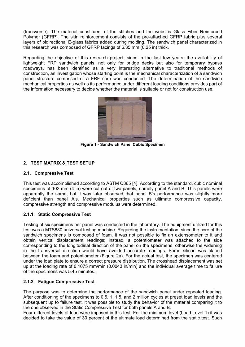
(transverse). The material constituent of the stitches and the webs is Glass Fiber Reinforced Polymer (GFRP). The skin reinforcement consists of the pre-attached GFRP fabric plus several layers of bidirectional E-glass fabrics added during molding. The sandwich panel characterized in this research was composed of GFRP facings of 6.35 mm (0.25 in) thick. Regarding the objective of this research project, since in the last few years, the availability of lightweight FRP sandwich panels, not only for bridge decks but also for temporary bypass roadways, has been identified as a very interesting alternative to traditional methods of construction, an investigation whose starting point is the mechanical characterization of a sandwich panel structure comprised of a FRF core was conducted. The determination of the sandwich mechanical properties as well as its performance under different loading conditions provides part of the information necessary to decide whether the material is suitable or not for construction use.
Figure 1 - Sandwich Panel Cubic Specimen
2. TEST MATRIX & TEST SETUP
2.1. Compressive Test
This test was accomplished according to ASTM C365 [4]. According to the standard, cubic nominal specimens of 102 mm (4 in) were cut out of two panels, namely panel A and B. This panels were apparently the same, but it was later observed that panel B’s performance was slightly more deficient than panel A’s. Mechanical properties such as ultimate compressive capacity, compressive strength and compressive modulus were determined.
2.1.1. Static Compressive Test
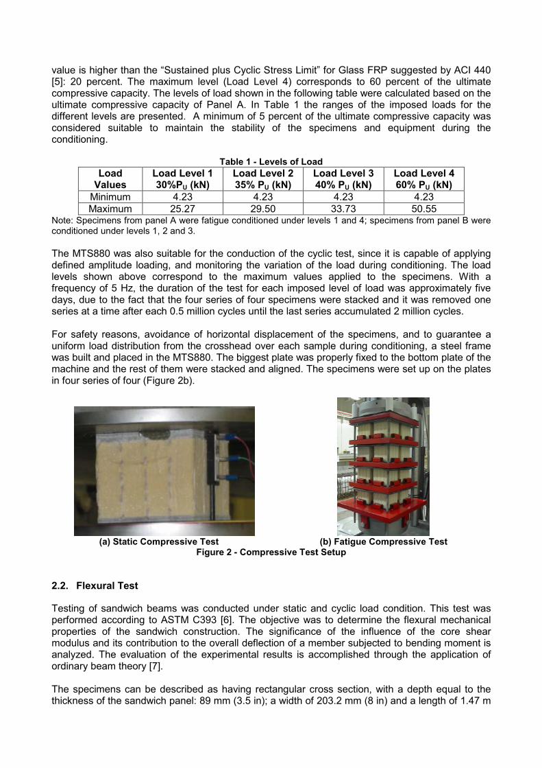
Testing of six specimens per panel was conducted in the laboratory. The equipment utilized for this test was a MTS880 universal testing machine. Regarding the instrumentation, since the core of the sandwich specimens is composed of foam, it was not possible to fix an extensometer to it and obtain vertical displacement readings; instead, a potentiometer was attached to the side corresponding to the longitudinal direction of the panel on the specimens, otherwise the widening in the transversal direction would have avoided accurate readings. Some silicon was placed between the foam and potentiometer (Figure 2a). For the actual test, the specimen was centered under the load plate to ensure a correct pressure distribution. The crosshead displacement was set up at the loading rate of 0.1075 mm/min (0.0043 in/min) and the individual average time to failure of the specimens was 5.45 minutes.
2.1.2. Fatigue Compressive Test
The purpose was to determine the performance of the sandwich panel under repeated loading. After conditioning of the specimens to 0.5, 1, 1.5, and 2 million cycles at preset load levels and the subsequent up to failure test, it was possible to study the behavior of the material comparing it to the one observed in the Static Compressive Test for both panels A and B. Four different levels of load were imposed in this test. For the minimum level (Load Level 1) it was decided to take the value of 30 percent of the ultimate load determined from the static test. Such
value is higher than the “Sustained plus Cyclic Stress Limit” for Glass FRP suggested by ACI 440 [5]: 20 percent. The maximum level (Load Level 4) corresponds to 60 percent of the ultimate compressive capacity. The levels of load shown in the following table were calculated based on the ultimate compressive capacity of Panel A. In Table 1 the ranges of the imposed loads for the different levels are presented. A minimum of 5 percent of the ultimate compressive capacity was considered suitable to maintain the stability of the specimens and equipment during the conditioning.
Table 1 - Levels of Load Load
Values Load Level 1 30%PU (kN)
Load Level 2 35% PU (kN)
Load Level 3 40% PU (kN)
Load Level 4 60% PU (kN)
Minimum 4.23 4.23 4.23 4.23 Maximum 25.27 29.50 33.73 50.55
Note: Specimens from panel A were fatigue conditioned under levels 1 and 4; specimens from panel B were conditioned under levels 1, 2 and 3. The MTS880 was also suitable for the conduction of the cyclic test, since it is capable of applying defined amplitude loading, and monitoring the variation of the load during conditioning. The load levels shown above correspond to the maximum values applied to the specimens. With a frequency of 5 Hz, the duration of the test for each imposed level of load was approximately five days, due to the fact that the four series of four specimens were stacked and it was removed one series at a time after each 0.5 million cycles until the last series accumulated 2 million cycles. For safety reasons, avoidance of horizontal displacement of the specimens, and to guarantee a uniform load distribution from the crosshead over each sample during conditioning, a steel frame was built and placed in the MTS880. The biggest plate was properly fixed to the bottom plate of the machine and the rest of them were stacked and aligned. The specimens were set up on the plates in four series of four (Figure 2b).
(a) Static Compressive Test (b) Fatigue Compressive Test Figure 2 - Compressive Test Setup
2.2. Flexural Test
Testing of sandwich beams was conducted under static and cyclic load condition. This test was performed according to ASTM C393 [6]. The objective was to determine the flexural mechanical properties of the sandwich construction. The significance of the influence of the core shear modulus and its contribution to the overall deflection of a member subjected to bending moment is analyzed. The evaluation of the experimental results is accomplished through the application of ordinary beam theory [7]. The specimens can be described as having rectangular cross section, with a depth equal to the thickness of the sandwich panel: 89 mm (3.5 in); a width of 203.2 mm (8 in) and a length of 1.47 m
(58 in). Due to the anisotropy of the material, two types of specimens were considered for testing: transversally-cut (y-direction) and longitudinally-cut (x-direction).
2.2.1. Static Flexural Test
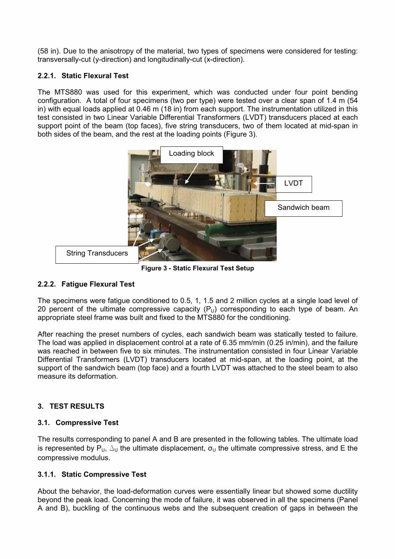
The MTS880 was used for this experiment, which was conducted under four point bending configuration. A total of four specimens (two per type) were tested over a clear span of 1.4 m (54 in) with equal loads applied at 0.46 m (18 in) from each support. The instrumentation utilized in this test consisted in two Linear Variable Differential Transformers (LVDT) transducers placed at each support point of the beam (top faces), five string transducers, two of them located at mid-span in both sides of the beam, and the rest at the loading points (Figure 3).
Figure 3 - Static Flexural Test Setup
2.2.2. Fatigue Flexural Test
The specimens were fatigue conditioned to 0.5, 1, 1.5 and 2 million cycles at a single load level of 20 percent of the ultimate compressive capacity (PU) corresponding to each type of beam. An appropriate steel frame was built and fixed to the MTS880 for the conditioning. After reaching the preset numbers of cycles, each sandwich beam was statically tested to failure. The load was applied in displacement control at a rate of 6.35 mm/min (0.25 in/min), and the failure was reached in between five to six minutes. The instrumentation consisted in four Linear Variable Differential Transformers (LVDT) transducers located at mid-span, at the loading point, at the support of the sandwich beam (top face) and a fourth LVDT was attached to the steel beam to also measure its deformation.
3. TEST RESULTS
3.1. Compressive Test
The results corresponding to panel A and B are presented in the following tables. The ultimate load is represented by PU, ∆U the ultimate displacement, σU the ultimate compressive stress, and E the compressive modulus. 3.1.1. Static Compressive Test About the behavior, the load-deformation curves were essentially linear but showed some ductility beyond the peak load. Concerning the mode of failure, it was observed in all the specimens (Panel A and B), buckling of the continuous webs and the subsequent creation of gaps in between the
Loading block
LVDT
Sandwich beam
String Transducers
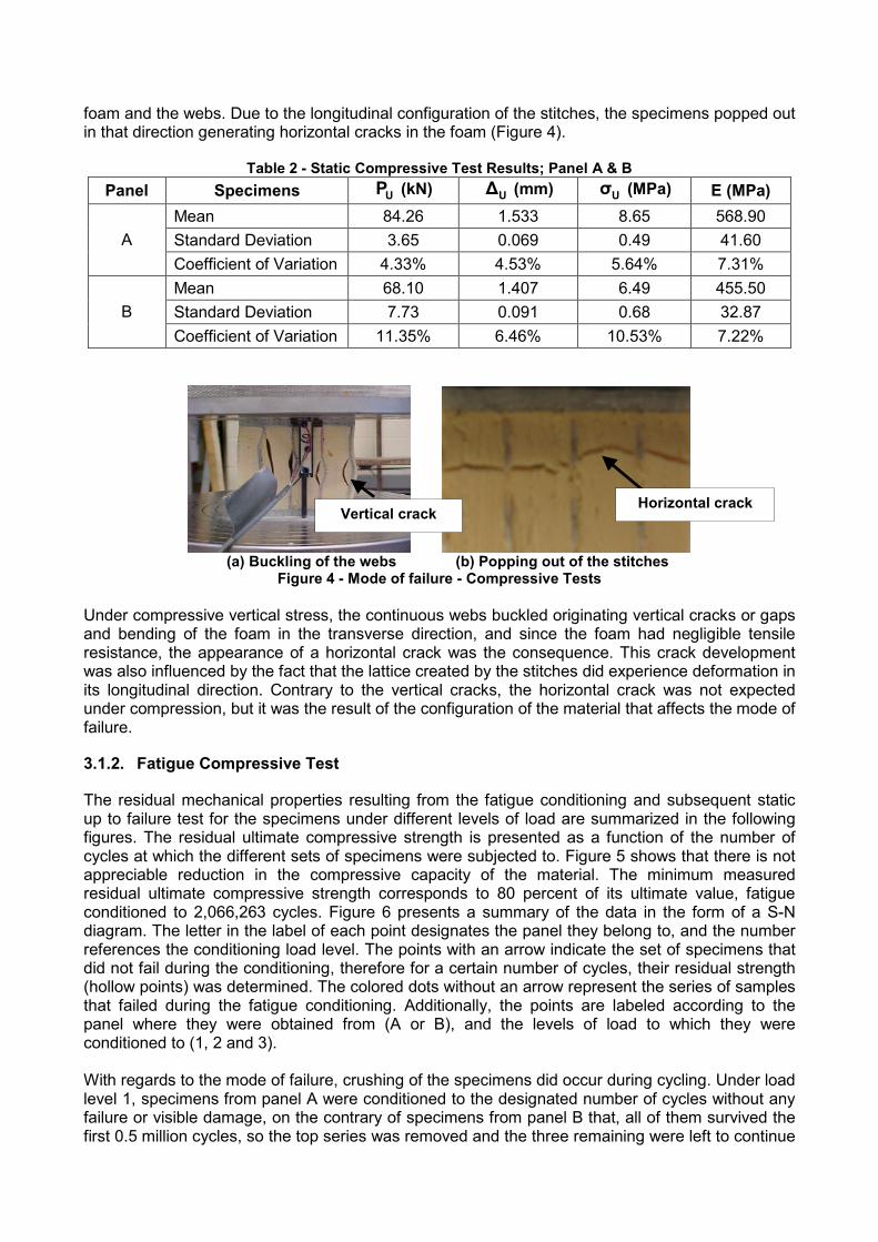
foam and the webs. Due to the longitudinal configuration of the stitches, the specimens popped out in that direction generating horizontal cracks in the foam (Figure 4).
Table 2 - Static Compressive Test Results; Panel A & B Panel Specimens UP (kN) U∆ (mm) Uσ (MPa) E (MPa)
Mean 84.26 1.533 8.65 568.90 Standard Deviation 3.65 0.069 0.49 41.60 ACoefficient of Variation 4.33% 4.53% 5.64% 7.31% Mean 68.10 1.407 6.49 455.50 Standard Deviation 7.73 0.091 0.68 32.87 BCoefficient of Variation 11.35% 6.46% 10.53% 7.22%
(a) Buckling of the webs (b) Popping out of the stitches Figure 4 - Mode of failure - Compressive Tests
Under compressive vertical stress, the continuous webs buckled originating vertical cracks or gaps and bending of the foam in the transverse direction, and since the foam had negligible tensile resistance, the appearance of a horizontal crack was the consequence. This crack development was also influenced by the fact that the lattice created by the stitches did experience deformation in its longitudinal direction. Contrary to the vertical cracks, the horizontal crack was not expected under compression, but it was the result of the configuration of the material that affects the mode of failure.
3.1.2. Fatigue Compressive Test
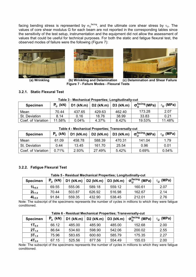
The residual mechanical properties resulting from the fatigue conditioning and subsequent static up to failure test for the specimens under different levels of load are summarized in the following figures. The residual ultimate compressive strength is presented as a function of the number of cycles at which the different sets of specimens were subjected to. Figure 5 shows that there is not appreciable reduction in the compressive capacity of the material. The minimum measured residual ultimate compressive strength corresponds to 80 percent of its ultimate value, fatigue conditioned to 2,066,263 cycles. Figure 6 presents a summary of the data in the form of a S-N diagram. The letter in the label of each point designates the panel they belong to, and the number references the conditioning load level. The points with an arrow indicate the set of specimens that did not fail during the conditioning, therefore for a certain number of cycles, their residual strength (hollow points) was determined. The colored dots without an arrow represent the series of samples that failed during the fatigue conditioning. Additionally, the points are labeled according to the panel where they were obtained from (A or B), and the levels of load to which they were conditioned to (1, 2 and 3). With regards to the mode of failure, crushing of the specimens did occur during cycling. Under load level 1, specimens from panel A were conditioned to the designated number of cycles without any failure or visible damage, on the contrary of specimens from panel B that, all of them survived the first 0.5 million cycles, so the top series was removed and the three remaining were left to continue
Vertical crack Horizontal crack
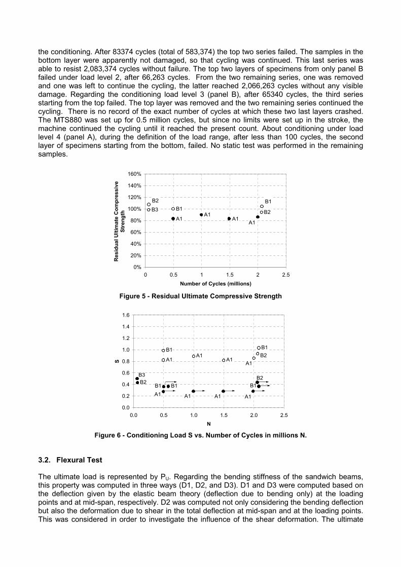
the conditioning. After 83374 cycles (total of 583,374) the top two series failed. The samples in the bottom layer were apparently not damaged, so that cycling was continued. This last series was able to resist 2,083,374 cycles without failure. The top two layers of specimens from only panel B failed under load level 2, after 66,263 cycles. From the two remaining series, one was removed and one was left to continue the cycling, the latter reached 2,066,263 cycles without any visible damage. Regarding the conditioning load level 3 (panel B), after 65340 cycles, the third series starting from the top failed. The top layer was removed and the two remaining series continued the cycling. There is no record of the exact number of cycles at which these two last layers crashed. The MTS880 was set up for 0.5 million cycles, but since no limits were set up in the stroke, the machine continued the cycling until it reached the present count. About conditioning under load level 4 (panel A), during the definition of the load range, after less than 100 cycles, the second layer of specimens starting from the bottom, failed. No static test was performed in the remaining samples.
A1A1
A1
B1 B2B3
A1
B1B2
0%
20%
40%
60%
80%
100%
120%
140%
160%
0 0.5 1 1.5 2 2.5Number of Cycles (millions)
Res
idua
lUlti
mat
eC
ompr
essi
veSt
reng
th
Figure 5 - Residual Ultimate Compressive Strength
B1B2
A1A1
A1
B1 B1
B1B2B3
A1A1A1A1
A1B2
B1
0.0
0.2
0.4
0.6
0.8
1.0
1.2
1.4
1.6
0.0 0.5 1.0 1.5 2.0 2.5N
S
Figure 6 - Conditioning Load S vs. Number of Cycles in millions N.
3.2. Flexural Test
The ultimate load is represented by PU. Regarding the bending stiffness of the sandwich beams, this property was computed in three ways (D1, D2, and D3). D1 and D3 were computed based on the deflection given by the elastic beam theory (deflection due to bending only) at the loading points and at mid-span, respectively. D2 was computed not only considering the bending deflection but also the deformation due to shear in the total deflection at mid-span and at the loading points. This was considered in order to investigate the influence of the shear deformation. The ultimate
facing bending stress is represented by σUfacing, and the ultimate core shear stress by τU. The
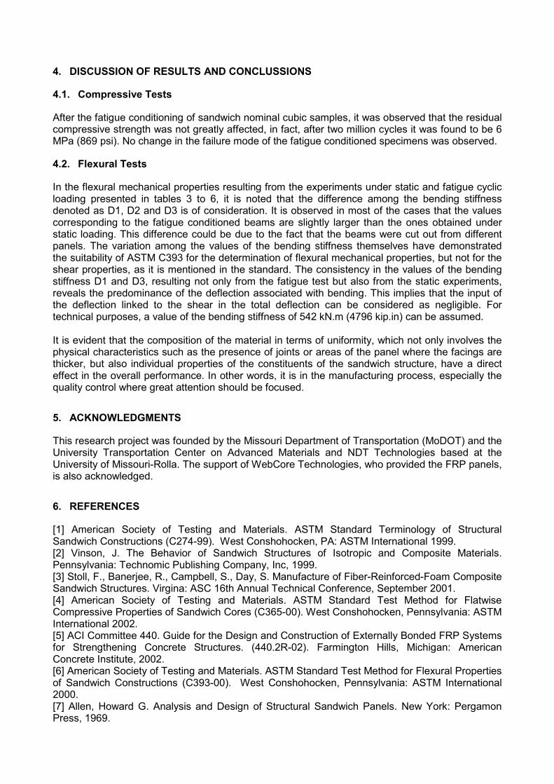
values of core shear modulus G for each beam are not reported in the corresponding tables since the sensitivity of the test setup, instrumentation and the equipment did not allow the assessment of values that could be useful for technical purposes. For both the static and fatigue flexural test, the observed modes of failure were the following (Figure 7):
(a) Wrinkling (b) Wrinkling and Delamination (c) Delamination and Shear Failure Figure 7 - Failure Modes - Flexural Tests
3.2.1. Static Flexural Test
Table 3 - Mechanical Properties; Longitudinally-cut Specimen UP (kN) D1 (kN.m) D2 (kN.m) D3 (kN.m) facing
Uσ (MPa) Uτ (MPa)
Mean 70.44 437.65 429.63 462.40 173.28 2.07 St. Deviation 8.14 0.16 18.76 38.99 33.83 0.21 Coef. of Variation 11.58% 0.04% 4.37% 8.42% 19.53% 11.48%
Table 4 - Mechanical Properties; Transversally-cut Specimen UP (kN) D1 (kN.m) D2 (kN.m) D3 (kN.m) facing
Uσ (MPa) Uτ (MPa)
Mean 61.09 458.78 588.39 470.31 141.04 1.79 St. Deviation 0.44 13.45 161.70 25.54 0.96 0.01 Coef. of Variation 0.71% 2.93% 27.49% 5.42% 0.69% 0.54%
3.2.2. Fatigue Flexural Test
Table 5 - Residual Mechanical Properties; Longitudinally-cut Specimen UP (kN) D1 (kN.m) D2 (kN.m) D3 (kN.m) facing
Uσ (MPa) Uτ (MPa)
1L0.5 69.55 555.06 589.18 559.12 160.61 2.07 2L1.0 70.44 503.87 626.92 516.98 162.67 2.14 4L2.0 91.84 559.35 432.90 538.45 212.01 2.76
Note: The subscript of the specimens represents the number of cycles in millions to which they were fatigue conditioned.
Table 6 - Residual Mechanical Properties; Transversally-cut
Specimen UP (kN) D1 (kN.m) D2 (kN.m) D3 (kN.m) facingUσ (MPa) Uτ (MPa)
1T0.5 66.12 485.00 485.90 485.00 152.68 2.00 2T1.0 86.64 534.60 598.90 542.06 200.02 2.55 3T1.5 75.96 583.65 600.60 585.79 175.35 2.27 4T2.0 67.15 525.56 877.56 554.49 155.03 2.00
Note: The subscript of the specimens represents the number of cycles in millions to which they were fatigue conditioned.
4. DISCUSSION OF RESULTS AND CONCLUSSIONS
4.1. Compressive Tests
After the fatigue conditioning of sandwich nominal cubic samples, it was observed that the residual compressive strength was not greatly affected, in fact, after two million cycles it was found to be 6 MPa (869 psi). No change in the failure mode of the fatigue conditioned specimens was observed.
4.2. Flexural Tests
In the flexural mechanical properties resulting from the experiments under static and fatigue cyclic loading presented in tables 3 to 6, it is noted that the difference among the bending stiffness denoted as D1, D2 and D3 is of consideration. It is observed in most of the cases that the values corresponding to the fatigue conditioned beams are slightly larger than the ones obtained under static loading. This difference could be due to the fact that the beams were cut out from different panels. The variation among the values of the bending stiffness themselves have demonstrated the suitability of ASTM C393 for the determination of flexural mechanical properties, but not for the shear properties, as it is mentioned in the standard. The consistency in the values of the bending stiffness D1 and D3, resulting not only from the fatigue test but also from the static experiments, reveals the predominance of the deflection associated with bending. This implies that the input of the deflection linked to the shear in the total deflection can be considered as negligible. For technical purposes, a value of the bending stiffness of 542 kN.m (4796 kip.in) can be assumed. It is evident that the composition of the material in terms of uniformity, which not only involves the physical characteristics such as the presence of joints or areas of the panel where the facings are thicker, but also individual properties of the constituents of the sandwich structure, have a direct effect in the overall performance. In other words, it is in the manufacturing process, especially the quality control where great attention should be focused.
5. ACKNOWLEDGMENTS
This research project was founded by the Missouri Department of Transportation (MoDOT) and the University Transportation Center on Advanced Materials and NDT Technologies based at the University of Missouri-Rolla. The support of WebCore Technologies, who provided the FRP panels, is also acknowledged.
6. REFERENCES
[1] American Society of Testing and Materials. ASTM Standard Terminology of Structural Sandwich Constructions (C274-99). West Conshohocken, PA: ASTM International 1999. [2] Vinson, J. The Behavior of Sandwich Structures of Isotropic and Composite Materials. Pennsylvania: Technomic Publishing Company, Inc, 1999. [3] Stoll, F., Banerjee, R., Campbell, S., Day, S. Manufacture of Fiber-Reinforced-Foam Composite Sandwich Structures. Virgina: ASC 16th Annual Technical Conference, September 2001. [4] American Society of Testing and Materials. ASTM Standard Test Method for Flatwise Compressive Properties of Sandwich Cores (C365-00). West Conshohocken, Pennsylvania: ASTM International 2002. [5] ACI Committee 440. Guide for the Design and Construction of Externally Bonded FRP Systems for Strengthening Concrete Structures. (440.2R-02). Farmington Hills, Michigan: American Concrete Institute, 2002. [6] American Society of Testing and Materials. ASTM Standard Test Method for Flexural Properties of Sandwich Constructions (C393-00). West Conshohocken, Pennsylvania: ASTM International 2000. [7] Allen, Howard G. Analysis and Design of Structural Sandwich Panels. New York: Pergamon Press, 1969.