Embed Size (px)
Citation preview
Mechanical engineering
KT calibration table
STEIN Maschinenbau Wartbachstrasse 9 66999 Hinterweidenthal, Germany
Telephone: (+49) (0)6396-9215-0 Fax: (+49) (0)6396-9215-25 E-mail: [email protected]
Equipment / options / additional equipment:
The following is a selection of different options/information/additional equipment for calibration tables:
Path measurement systems for all travel axes Upon request, path measuring systems may be attached to determine the positions of the axes for all of the machine's travel axes. These support repeatability for set-tings involving specific production applications and enable more exact positioning of the respective axis during production in case of corrective measures.
Filter systems Filter systems are used in the calibration table for additional filtering of the feed wa-ter and/or in case of further use of collected water in the main water tank. Simple cartridge filters, cartridge filters with a return flushing function (manual), switching double filter systems, or self-cleaning filter systems with adjustable cleaning intervals or input/output pressure compensation may be used.
Fan system for air drying Special side channel compressor are used in multiple power levels for air drying the profile extrudate while leaving the calibration table. To transfer the blowing air to the profile extrudate, special distributors are attached at the end of the calibration table, which feature connection options for all available variations of bending hose sys-tems. Upon request, the system may also be designed for frequency controls to reduce power consumption as required.
Vacuum generator To generate a vacuum at the various areas of the calibration table, there is a diverse range of vacuum generators available from different manufacturers. The selection includes uncontrolled standard vacuum pumps, controlled vacuum pumps, and so-phisticated systems with air/water separation and additional controller options. Often, low vacuum requirements but high air throughput quantity utilise side channel com-pressor for generation. The goal during selection is of course to achieve the required vacuum quantity with the lowest possible energy consumption, which necessarily leads to the controlled variation of the vacuum generator.
Cyclone units Due to the high water quantity that is required to supply vacuum tanks, cyclone technology is usually utilised for a low-level vacuum. In this case, a separate water output pump and vacuum generator combined with an air/water separation container separate the air-water mixture and return it separately from the units. Variable op-tions include individual cyclone units for specific areas or a central cyclone system with a connection option for multiple consumers. Even with cyclone units, the variation with regard to vacuum producers is diverse, depending on the required performance, application, and energy efficiency.
Mechanical engineering
KT calibration table
STEIN Maschinenbau Wartbachstrasse 9 66999 Hinterweidenthal, Germany
Telephone: (+49) (0)6396-9215-0 Fax: (+49) (0)6396-9215-25 E-mail: [email protected]
Calibration table for dry calibration tools, vacuum tanks, and additional attachments
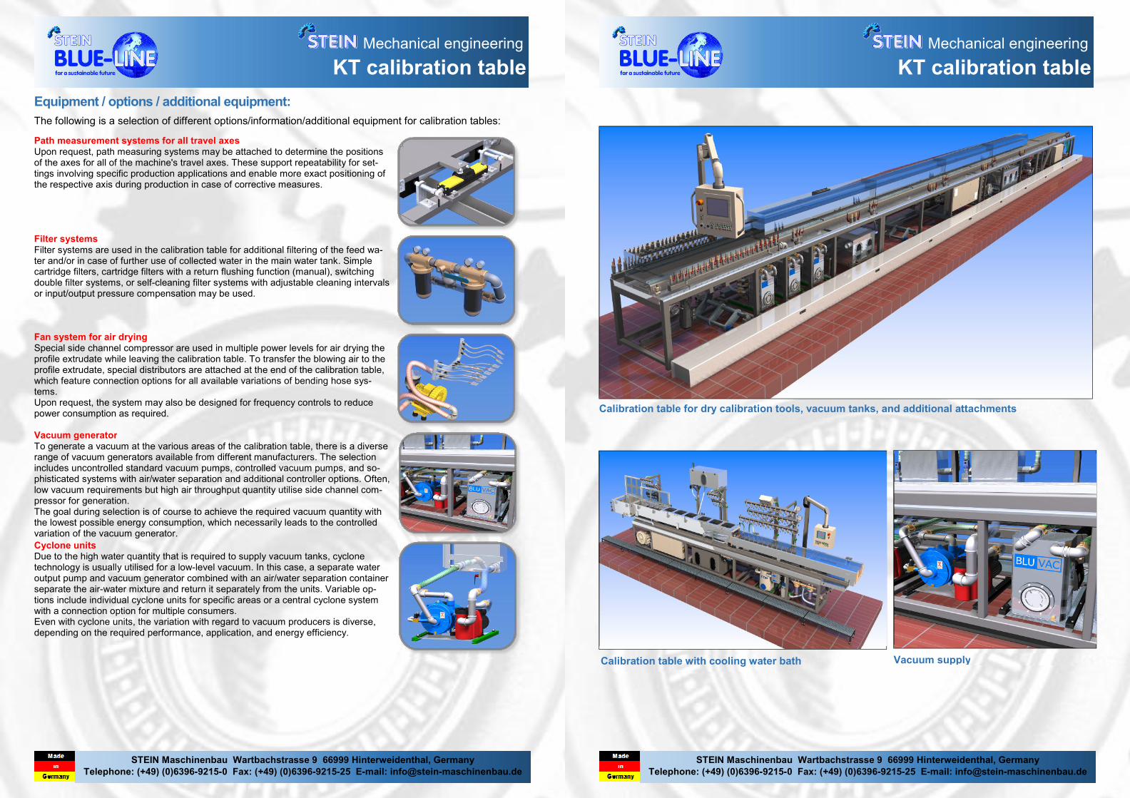
Calibration table with cooling water bath
Vacuum supply

Mechanical engineering
KT calibration table
STEIN Maschinenbau Wartbachstrasse 9 66999 Hinterweidenthal, Germany
Telephone: (+49) (0)6396-9215-0 Fax: (+49) (0)6396-9215-25 E-mail: [email protected]
Basic information about STEIN Maschinenbau calibration tables
STEIN Maschinenbau builds calibration tables adjusted especially to customer needs based on several of our own standard
versions. This means:
� The calibration table may be designed and produced in the desired length.
� The working height may be adjusted according to the tools used and the tool mounts.
� The type and number of vacuum generators is coordinated and installed with the customer.
� Positions, quantity, connection sizes, connection type (e.g.: coupling, ball valve, etc.) of the distributor for the tool
supply may also be specified.
� The water/vacuum system is generally specified with the customer using a flow diagram created especially for this
purpose.
� Technical controller functions and the layout of the control panel may be specified.
For each of these customisation options, please note that these must remain within the scope of design, technical fluid, and
technical electronic possibilities.
Basic structure
� Main frame consisting of welded hollow stainless steel
profiles.
� All components that are in contact with water compris-
ing stainless steel or suitable plastics.
� Motors that come into contact with water feature corre-
sponding splash-proof paint and sealing in the corre-
sponding protection class.
� In case of bearing supports, maintenance-free bearings
are used if available.
� Functional screw-connections consisting of stainless
steel, brass, or nickel-plated brass. Ball valves are
mainly designed as a full throughput version.
Basic mechanical structure of all calibration tables
� Height adjustment (vertical travel): There are different systems for height adjustment of the calibration tables that are
selected by us depending on the calibration table and adjusted as required.
� Longitudinal adjustment The longitudinal adjustment of a calibration table takes place either by moving the complete
machine or by moving the tool carrier. Both variations are essentially possible, but they both have their advantages
and disadvantages.
� Traverse movement (moving perpendicular to the extrusion axis). Traverse movement normally takes place by moving
the tool carrier. In part, additional ability to tilt the tool carrier is also required in this case. There are a variety of solu-
tions for both movements that are selected according to the requirements.
� Vacuum generator: All vacuum generators are mounted for speedy exchange or repair or maintenance work using
sliding rails. Hose connections feature couplings. Electrical connection are designed as snap-in or screw connections.
� Every calibration table requires a main water container. Depending on the water/vacuum system, the tasks of this tank
are diverse. One task is the collection of the return feed water from all consumers of the calibration table, the disposal
of the air extracted via the vacuum generators, and the return of return feed water to the operating water system. To
minimise noise, the return feed lines of the vacuum generator are built into the tank in suppressing pipes. A ventilation
tunnel is used to dispose of excess air, which simultaneously functions as a collective return feed. In order to clean the
tank, a sufficient number of viewing windows are built in, which also serve as cleaning openings.
� All attachments on the calibration table are laid out so that splashing water is caught and guided away as best as pos-
sible. The catching tray feature sufficient drains with large dimensioning. Multiple perforated metal inserts in the drains
enable the draining water to be pre-filtered.
� Additional customer-specific attachments may be included in the design of the calibration table upon request.
Electrical technology (in general)
� The switching cabinets are integrated in the main
frames of the calibration tables as far as possible. In
case space is lacking, the switching cabinets must be
attached externally.
� The control panel and additional control elements are
integrated in a separate control box. This is usually fas-
tened hanging on a swivelling support arm system in
the inlet area (may also be lifted in case of larger control
boxes).
� For control/regulation, we use components from Sie-
mens, and for motor regulation, we use SEW frequency
inverters.
Mechanical engineering
KT calibration table
STEIN Maschinenbau Wartbachstrasse 9 66999 Hinterweidenthal, Germany
Telephone: (+49) (0)6396-9215-0 Fax: (+49) (0)6396-9215-25 E-mail: [email protected]
Calibration tables with cooling water bath
For this variation of the calibration tables, the water bath and its installations and attachments forms the main characteris-tic. In this case, the calibration tools are usually fastened to the tray on the inlet side and, depending on the size and resulting weight, they are often supported on the inside of the tray as well. In this case, diverse variations for fastening the tools to the tray are available, depending on the tool manu-facturer or the company's own systems. Important criteria for installation are of course rigidity, sealing, accessibility (con-nections), and the option for speedy exchange of the tools if production is changed. An additional criterion is optimal distribution of the cooling water according to the temperature conditions in the water bath, and the ability to fill the tray and empty it quickly as required. Often, additional devices are also built in, and holders need to be planned for this. In this way, a flexible design for the water baths and exact coordination with the later operator of the machine are required. Of course, every alignment option for the extruder nozzle is also available in this case.
Temperature regulation for calibration tables
In order to keep the water consumption of calibration tables as low and as energy-efficient as possible, the main water tank of the machine may be designed so that return feed water, pro-vided it is still usable in terms of temperature conditions, is able to be fed back into the circuits of specific consumers. In this case, temperature regulation is usually completed by feeding in fresh water from the company's own system. Additional tem-perature regulation (cooling or heating) is usually only possible by installing (partially external) tempering and/or cooling devic-es. The installation options and the functionality in the system must be check case-by-case.
Calibration tables for dry calibration
A significant property of these calibration tables is the clamp-ing frame, which acts as a support for the calibration tools and the subsequent vacuum tanks and any possible water baths. Our preferred variation in this case is an angled C-rail with high wall thickness. This is advantageous thanks to geometrical properties like: High rigidity, low elasticity, high supporting capacity, and more. The actual fastener for the tool and the subsequent structures are naturally dependent on this and the options are therefore accordingly diverse. For this reason, we are flexible in terms of dimensions and fas-tening variables and design these as required. The clamping frame may be combined with the machine's height adjustment to align the position of the calibration tool to the extruder nozzle. For this reason, a traverse movement axis and sometimes also a tilting option along the longitudinal axis are required as well. Both are integrated in the clamping frame, although the tilting offset is designed optionally.