Embed Size (px)
Citation preview
7/25/2019 Mechanics of Materials Solutions Chapter09 Probs38 53
http://slidepdf.com/reader/full/mechanics-of-materials-solutions-chapter09-probs38-53 1/29
Excerpts from this work may be reproduced by instructors for distribution on a not-for-profit basis for testing or instructional purposes onlyto students enrolled in courses for which the textbook has been adopted. Any other reproduction or translation of this work beyond that
permitted by Sections 107 or 108 of the 1976 United States Copyright Act without the permission of the copyright owner is unlawful.
9.38 A wooden beam is fabricated from one 2 × 8 and two 2 × 4 piecesof dimension lumber to form the I-beam cross section shown in Fig.
P9.38. The flanges of the beam are fastened to the web with nails that
can safely transmit a force of 100 lb in direct shear. If the beam issimply supported and carries a 1000-lb load at the center of a 12-ft span,
determine:
(a) the horizontal force transferred from each flange to the web in a 12-
in. long segment of the beam.
(b) the maximum spacing s (along the length of the beam) required forthe nails.
(c) the maximum horizontal shear stress in the I-beam.
Fig. P9.38
Solution
Moment of inertia about the z axis:
Shape Width b Height h I C d = yi – y
d²A I C + d²A (in.) (in.) (in.4) (in.) (in.
4) (in.
4)
top flange 4 2 2.6667 5 200.0000 202.6667
web 2 8 85.3333 0 0.0000 85.3333
bottom flange 4 2 2.6667 −5 200.0000 202.6667
Moment of inertia about the z axis (in.4) = 490.6667
Maximum shear force
For P = 1,000 lb, V = P /2 = 500 lb
(a) Horizontal force transferred from each flange
(in a 12-in. length):3
3
4
(4 in.)(2 in.)(5 in.) 40 in.
(500 lb)(40 in. )40.761 lb/in.
490.6667 in.
(40.761 lb/in.)(12 in.) 489 lb H
Q
VQq
I
F
= =
= = =
= = Ans.
(b) Maximum nail spacing:
(1 nail)(100 lb/nail)
2.45 in.40.761 lb/in.
f f
f f
q s n V
n V
s q
≤
∴ ≤ = = Ans.
(c) Maximum horizontal shear stress: 3
3
4
(4 in.)(2 in.)(5 in.) (2 in.)(4 in.)(2 in.) 56 in.
(500 lb)(56 in. )28.5 psi
(490.6667 in. )(2 in.)
Q
τ
= + =
= = Ans.
7/25/2019 Mechanics of Materials Solutions Chapter09 Probs38 53
http://slidepdf.com/reader/full/mechanics-of-materials-solutions-chapter09-probs38-53 2/29
Excerpts from this work may be reproduced by instructors for distribution on a not-for-profit basis for testing or instructional purposes onlyto students enrolled in courses for which the textbook has been adopted. Any other reproduction or translation of this work beyond that
permitted by Sections 107 or 108 of the 1976 United States Copyright Act without the permission of the copyright owner is unlawful.
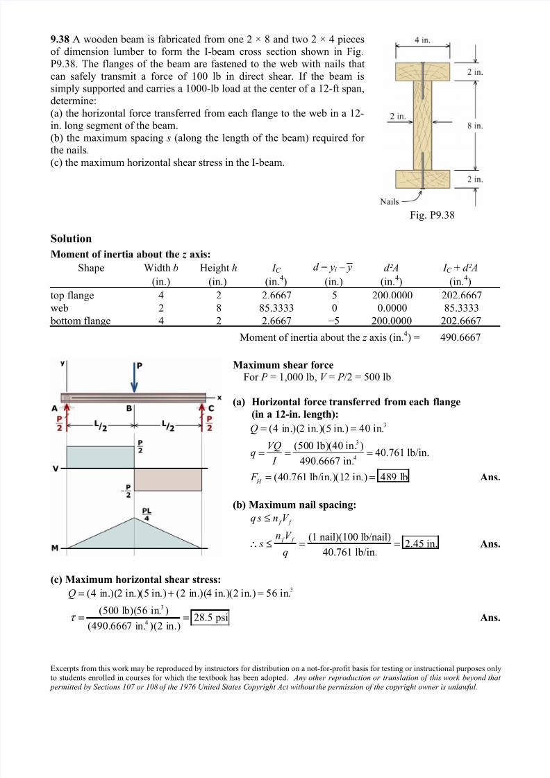
9.39 A wooden beam is fabricated from one 2 × 8 and two 2 × 4 pieces
of dimension lumber to form the I-beam cross section shown in Fig.P9.39. The I-beam will be used as a simply supported beam to carry a
concentrated load P at the center of a 20-ft span. The wood has an
allowable bending stress of 1,200 psi and an allowable shear stress of 90 psi. The flanges of the beam are fastened to the web with nails that can
safely transmit a force of 100 lb in direct shear.
(a) If the nails are uniformly spaced at an interval of s = 3.5 in. along the
span, what is the maximum concentrated load P that can be supported bythe beam? Demonstrate that the bending and shear stresses produced by
P are acceptable.
(b) Determine the magnitude of load P that produces the allowable
bending stress in the span (i.e., σ b = 1,200 psi). What nail spacing s is
required to support this load magnitude?
Fig. P9.39
Solution
Moment of inertia about the z axis:
Shape Width b Height h I C d = yi – y
d²A I C + d²A (in.) (in.) (in.4) (in.) (in.
4) (in.
4)
top flange 4 2 2.6667 5 200.0000 202.6667
web 2 8 85.3333 0 0.0000 85.3333
bottom flange 4 2 2.6667 −5 200.0000 202.6667
Moment of inertia about the z axis (in.4) = 490.6667
Maximum shear force
For P = 1,000 lb, V = P /2 = 500 lb
(a) Maximum concentrated load P :3(4 in.)(2 in.)(5 in.) 40 in.
(1 nail)(100 lb/nail)28.571 lb/in.
3.5 in.
f f
f f
Q
q s n V
n V q
s
= =
≤
∴ ≤ = =
4
3
max
(28.571 lb/in.)(490.6667 in. )350.5 lb
40 in.
701 lb2
VQq
I
q I V
Q
P V P
=
∴ = = =
= ∴ = Ans.
7/25/2019 Mechanics of Materials Solutions Chapter09 Probs38 53
http://slidepdf.com/reader/full/mechanics-of-materials-solutions-chapter09-probs38-53 3/29
Excerpts from this work may be reproduced by instructors for distribution on a not-for-profit basis for testing or instructional purposes onlyto students enrolled in courses for which the textbook has been adopted. Any other reproduction or translation of this work beyond that
permitted by Sections 107 or 108 of the 1976 United States Copyright Act without the permission of the copyright owner is unlawful.
(b) Magnitude of load P that produces the allowable bending stress in the span:
4
max
maxmax
1,200 psi
(1,200 psi)(490.6667 in. )98,133.34 lb-in.
6 in.
4
4 4(98,133.34 lb-in.)1,635.56 lb 1,636 lb
(20 ft)(12 in./ft)
x
M c
I
M
P L M
M P
L
σ = ≤
∴ ≤ =
=
∴ = = = = Ans.
Required nail spacing s:
maxmax
3
4
1,635.56 lb817.78 lb
2 2
(817.78 lb)(40 in. )66.67 lb/in.
490.6667 in.
(1 nail)(100 lb) 1.500 in.66.67 lb/in.
f f
f f
P V
VQq
I
q s n V
n V sq
= = =
= = =
≤
∴ ≤ = = Ans.
7/25/2019 Mechanics of Materials Solutions Chapter09 Probs38 53
http://slidepdf.com/reader/full/mechanics-of-materials-solutions-chapter09-probs38-53 4/29
Excerpts from this work may be reproduced by instructors for distribution on a not-for-profit basis for testing or instructional purposes onlyto students enrolled in courses for which the textbook has been adopted. Any other reproduction or translation of this work beyond that
permitted by Sections 107 or 108 of the 1976 United States Copyright Act without the permission of the copyright owner is unlawful.
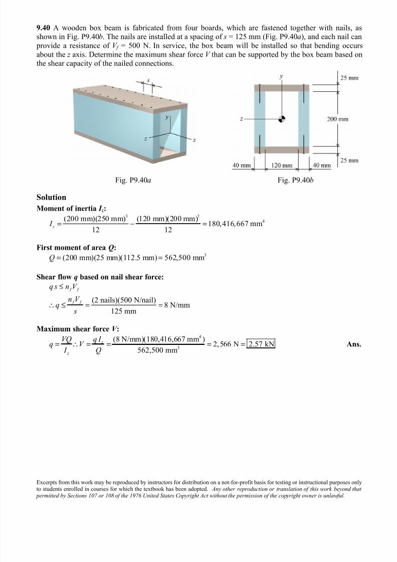
9.40 A wooden box beam is fabricated from four boards, which are fastened together with nails, asshown in Fig. P9.40b. The nails are installed at a spacing of s = 125 mm (Fig. P9.40a), and each nail can
provide a resistance of V f = 500 N. In service, the box beam will be installed so that bending occurs
about the z axis. Determine the maximum shear force V that can be supported by the box beam based onthe shear capacity of the nailed connections.
Fig. P9.40a Fig. P9.40b
SolutionMoment of inertia I z :
3 34(200 mm)(250 mm) (120 mm)(200 mm)
180,416,667 mm12 12
z I = − =
First moment of area Q:3(200 mm)(25 mm)(112.5 mm) 562,500 mmQ = =
Shear flow q based on nail shear force:
(2 nails)(500 N/nail)8 N/mm
125 mm
f f
f f
q s n V
n V q
s
≤
∴ ≤ = =
Maximum shear force V :4
3
(8 N/mm)(180,416,667 mm )2,566 N 2.57 kN
562,500 mm
z
z
VQ q I q V
I Q= ∴ = = = = Ans.
7/25/2019 Mechanics of Materials Solutions Chapter09 Probs38 53
http://slidepdf.com/reader/full/mechanics-of-materials-solutions-chapter09-probs38-53 5/29
Excerpts from this work may be reproduced by instructors for distribution on a not-for-profit basis for testing or instructional purposes onlyto students enrolled in courses for which the textbook has been adopted. Any other reproduction or translation of this work beyond that
permitted by Sections 107 or 108 of the 1976 United States Copyright Act without the permission of the copyright owner is unlawful.
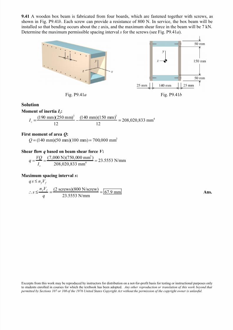
9.41 A wooden box beam is fabricated from four boards, which are fastened together with screws, asshown in Fig. P9.41b. Each screw can provide a resistance of 800 N. In service, the box beam will be
installed so that bending occurs about the z axis, and the maximum shear force in the beam will be 7 kN.
Determine the maximum permissible spacing interval s for the screws (see Fig. P9.41a).
Fig. P9.41a Fig. P9.41b
Solution
Moment of inertia I z :3 3
4(190 mm)(250 mm) (140 mm)(150 mm)208,020,833 mm
12 12 z I = − =
First moment of area Q:3(140 mm)(50 mm)(100 mm) 700,000 mmQ = =
Shear flow q based on beam shear force V :3
4
(7,000 N)(750,000 mm )23.5553 N/mm
208,020,833 mm z
VQq
I = = =
Maximum spacing interval s:
(2 screws)(800 N/screw)67.9 mm
23.5553 N/mm
f f
f f
q s n V
n V s
q
≤
∴ ≤ = = Ans.
7/25/2019 Mechanics of Materials Solutions Chapter09 Probs38 53
http://slidepdf.com/reader/full/mechanics-of-materials-solutions-chapter09-probs38-53 6/29
Excerpts from this work may be reproduced by instructors for distribution on a not-for-profit basis for testing or instructional purposes onlyto students enrolled in courses for which the textbook has been adopted. Any other reproduction or translation of this work beyond that
permitted by Sections 107 or 108 of the 1976 United States Copyright Act without the permission of the copyright owner is unlawful.
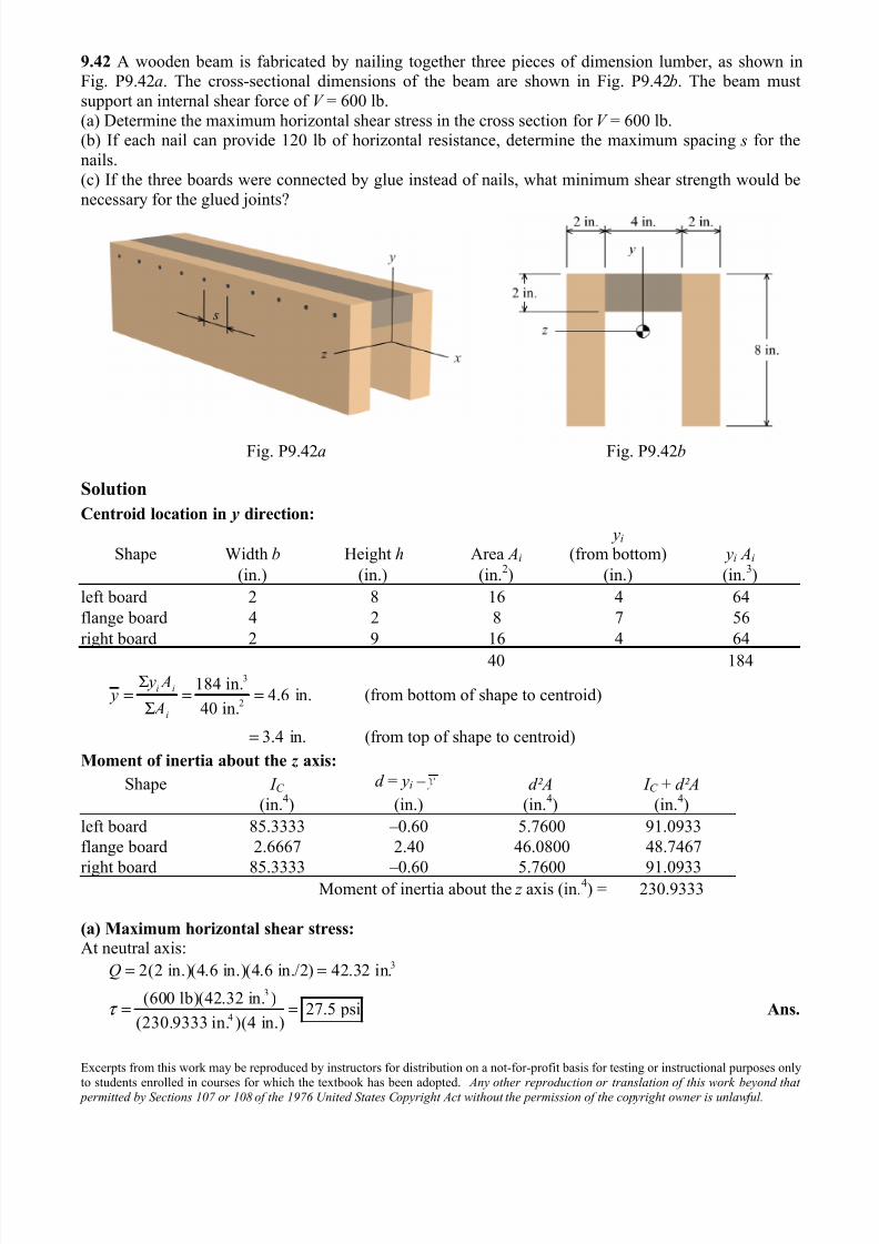
9.42 A wooden beam is fabricated by nailing together three pieces of dimension lumber, as shown inFig. P9.42a. The cross-sectional dimensions of the beam are shown in Fig. P9.42b. The beam must
support an internal shear force of V = 600 lb.
(a) Determine the maximum horizontal shear stress in the cross section for V = 600 lb.(b) If each nail can provide 120 lb of horizontal resistance, determine the maximum spacing s for the
nails.
(c) If the three boards were connected by glue instead of nails, what minimum shear strength would be
necessary for the glued joints?
Fig. P9.42a Fig. P9.42b
Solution
Centroid location in y direction:
Shape Width b Height h Area Ai
yi (from bottom) yi Ai
(in.) (in.) (in.2) (in.) (in.
3)
left board 2 8 16 4 64
flange board 4 2 8 7 56
right board 2 9 16 4 64
40 1843
2
184 in.4.6 in. (from bottom of shape to centroid)
40 in.
3.4 in. (from top of shape to centroid)
i i
i
y A y
A
Σ= = =
Σ
=
Moment of inertia about the z axis:
Shape I C d = yi – d²A I C + d²A
(in.4) (in.) (in.
4) (in.
4)
left board 85.3333 –0.60 5.7600 91.0933
flange board 2.6667 2.40 46.0800 48.7467
right board 85.3333 –0.60 5.7600 91.0933Moment of inertia about the z axis (in.
4) = 230.9333
(a) Maximum horizontal shear stress:
At neutral axis:3
3
4
2(2 in.)(4.6 in.)(4.6 in./2) 42.32 in.
(600 lb)(42.32 in. )27.5 psi
(230.9333 in. )(4 in.)
Q
τ
= =
= = Ans.
7/25/2019 Mechanics of Materials Solutions Chapter09 Probs38 53
http://slidepdf.com/reader/full/mechanics-of-materials-solutions-chapter09-probs38-53 7/29
Excerpts from this work may be reproduced by instructors for distribution on a not-for-profit basis for testing or instructional purposes onlyto students enrolled in courses for which the textbook has been adopted. Any other reproduction or translation of this work beyond that
permitted by Sections 107 or 108 of the 1976 United States Copyright Act without the permission of the copyright owner is unlawful.
Shear flow q based on beam shear force V :3
3
4
(4 in.)(2 in.)(3.4 in. 1 in.) 19.20 in.
(600 lb)(19.20 in. )49.8845 lb/in.
230.9333 in. z
Q
VQq
I
= − =
= = =
(b) Maximum spacing interval s:
(2 nails)(120 lb/nail)4.81 in.
49.8845 lb/in.
f f
f f
q s n V
n V s
q
≤
∴ ≤ = = Ans.
(c) Glue joint shear stress:
49.8845 lb/in.12.47 psi
2(2 in.)τ = = Ans.
7/25/2019 Mechanics of Materials Solutions Chapter09 Probs38 53
http://slidepdf.com/reader/full/mechanics-of-materials-solutions-chapter09-probs38-53 8/29
Excerpts from this work may be reproduced by instructors for distribution on a not-for-profit basis for testing or instructional purposes onlyto students enrolled in courses for which the textbook has been adopted. Any other reproduction or translation of this work beyond that
permitted by Sections 107 or 108 of the 1976 United States Copyright Act without the permission of the copyright owner is unlawful.
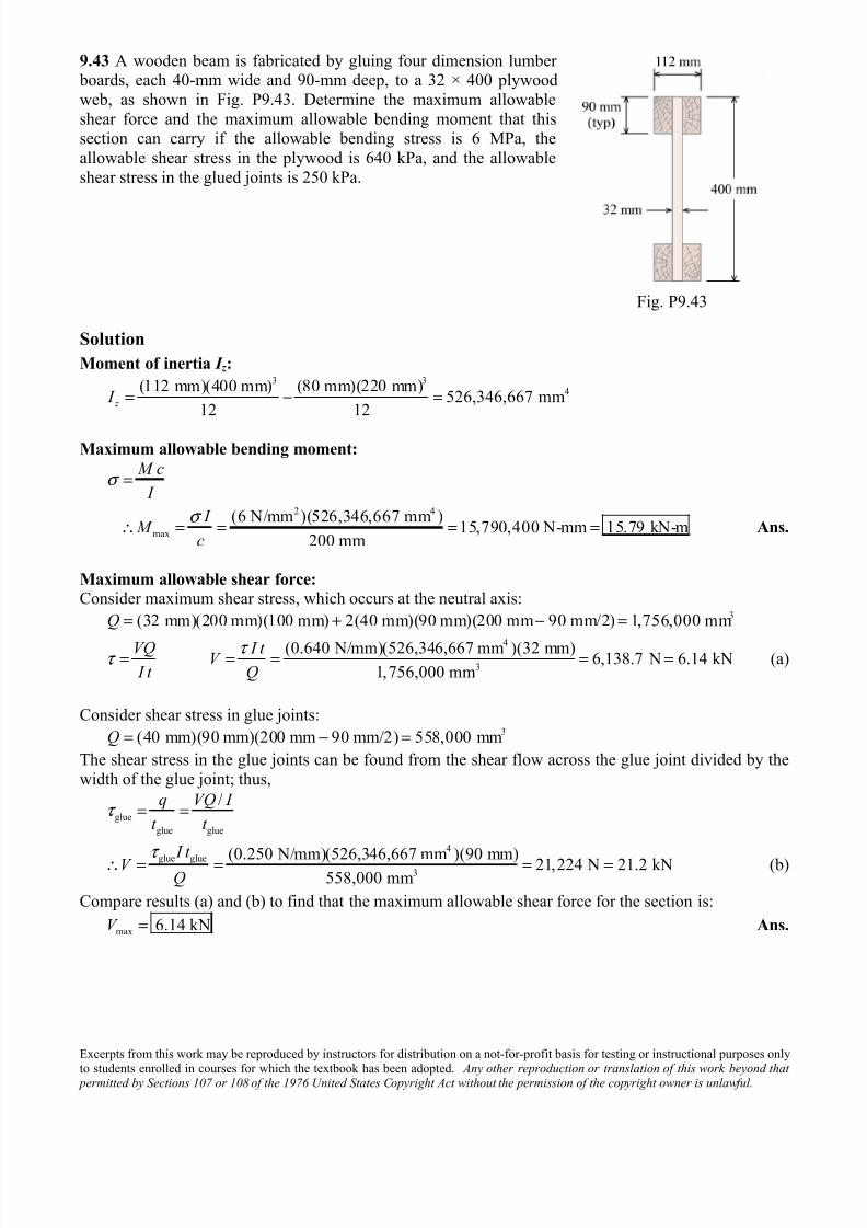
9.43 A wooden beam is fabricated by gluing four dimension lumber boards, each 40-mm wide and 90-mm deep, to a 32 × 400 plywood
web, as shown in Fig. P9.43. Determine the maximum allowable
shear force and the maximum allowable bending moment that thissection can carry if the allowable bending stress is 6 MPa, the
allowable shear stress in the plywood is 640 kPa, and the allowable
shear stress in the glued joints is 250 kPa.
Fig. P9.43
Solution
Moment of inertia I z :3 3
4(112 mm)(400 mm) (80 mm)(220 mm)526,346,667 mm
12 12 z I = − =
Maximum allowable bending moment:
2 4
max
(6 N/mm )(526,346,667 mm )15,790,400 N-mm 15.79 kN-m
200 mm
M c
I
I M
c
σ
σ
=
∴ = = = = Ans.
Maximum allowable shear force:
Consider maximum shear stress, which occurs at the neutral axis:3
4
3
(32 mm)(200 mm)(100 mm) 2(40 mm)(90 mm)(200 mm 90 mm/2) 1,756,000 mm
(0.640 N/mm)(526,346,667 mm )(32 mm) 6,138.7 N 6.14 kN1,756,000 mm
Q
VQ I t V I t Q
τ τ
= + − =
= = = = = (a)
Consider shear stress in glue joints:3(40 mm)(90 mm)(200 mm 90 mm/2) 558,000 mmQ = − =
The shear stress in the glue joints can be found from the shear flow across the glue joint divided by the
width of the glue joint; thus,
glue
glue glue
4
glue glue3
/
(0.250 N/mm)(526,346,667 mm )(90 mm) 21,224 N 21.2 kN558,000 mm
q VQ I
t t
I t V
Q
τ
τ
= =
∴ = = = = (b)
Compare results (a) and (b) to find that the maximum allowable shear force for the section is:
max 6.14 kNV = Ans.
7/25/2019 Mechanics of Materials Solutions Chapter09 Probs38 53
http://slidepdf.com/reader/full/mechanics-of-materials-solutions-chapter09-probs38-53 9/29
Excerpts from this work may be reproduced by instructors for distribution on a not-for-profit basis for testing or instructional purposes onlyto students enrolled in courses for which the textbook has been adopted. Any other reproduction or translation of this work beyond that
permitted by Sections 107 or 108 of the 1976 United States Copyright Act without the permission of the copyright owner is unlawful.
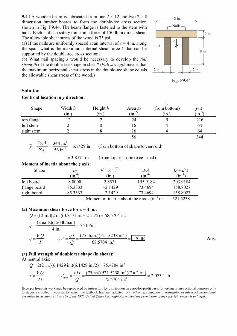
9.44 A wooden beam is fabricated from one 2 × 12 and two 2 × 8dimension lumber boards to form the double-tee cross section
shown in Fig. P9.44. The beam flange is fastened to the stem with
nails. Each nail can safely transmit a force of 150 lb in direct shear.The allowable shear stress of the wood is 75 psi.
(a) If the nails are uniformly spaced at an interval of s = 4 in. along
the span, what is the maximum internal shear force V that can be
supported by the double-tee cross section?
(b) What nail spacing s would be necessary to develop the full strength of the double-tee shape in shear? ( Full strength means that
the maximum horizontal shear stress in the double-tee shape equalsthe allowable shear stress of the wood.)
Fig. P9.44
Solution
Centroid location in y direction:
Shape Width b Height h Area Ai
yi
(from bottom) yi Ai
(in.) (in.) (in.2) (in.) (in.
3)
top flange 12 2 24 9 216
left stem 2 8 16 4 64
right stem 2 8 16 4 64
56 3443
2
344 in.6.1429 in. (from bottom of shape to centroid)
56 in.
3.8571 in. (from top of shape to centroid)
i i
i
y A y
A
Σ= = =
Σ
=
Moment of inertia about the z axis:
Shape I C d = yi – d²A I C + d²A
(in.4
) (in.) (in.4
) (in.4
)left board 8.0000 2.8571 195.9184 203.9184
flange board 85.3333 –2.1429 73.4694 158.8027
right board 85.3333 –2.1429 73.4694 158.8027
Moment of inertia about the z axis (in.4) = 521.5238
(a) Maximum shear force for s = 4 in.:3
4
3
(12 in.)(2 in.)(3.8571 in. 2 in./2) 68.5704 in.
(2 nails)(150 lb/nail)75 lb/in.
4 in.
(75 lb/in.)(521.5238 in. ) 570 lb68.5704 in.
Q
q
V Q q I q V I Q
= − =
= =
= ∴ = = = Ans.
(a) Full strength of double tee shape (in shear):
At neutral axis:3
4
max 3
2(2 in.)(6.1429 in.)(6.1429 in./2) 75.4704 in.
(75 psi)(521.5238 in. )(2 2 in.)2,073.1 lb
75.4704 in.
Q
V Q I t V
I t Q
τ τ
= =
×= ∴ = = =
7/25/2019 Mechanics of Materials Solutions Chapter09 Probs38 53
http://slidepdf.com/reader/full/mechanics-of-materials-solutions-chapter09-probs38-53 10/29
Excerpts from this work may be reproduced by instructors for distribution on a not-for-profit basis for testing or instructional purposes onlyto students enrolled in courses for which the textbook has been adopted. Any other reproduction or translation of this work beyond that
permitted by Sections 107 or 108 of the 1976 United States Copyright Act without the permission of the copyright owner is unlawful.
Consider nailed portion (i.e., top flange only) to establish required nail spacing:3
4
max
(2,073.1 lb)(68.5704 in. )272.57 lb/in.
521.5238 in.
(2 nails)(150 lb/nail)1.101 in.
272.57 lb/in.
f f
f f
V Qq
I
q s n V
n V s
q
= = =
≤
∴ ≤ = = Ans.
7/25/2019 Mechanics of Materials Solutions Chapter09 Probs38 53
http://slidepdf.com/reader/full/mechanics-of-materials-solutions-chapter09-probs38-53 11/29
Excerpts from this work may be reproduced by instructors for distribution on a not-for-profit basis for testing or instructional purposes onlyto students enrolled in courses for which the textbook has been adopted. Any other reproduction or translation of this work beyond that
permitted by Sections 107 or 108 of the 1976 United States Copyright Act without the permission of the copyright owner is unlawful.
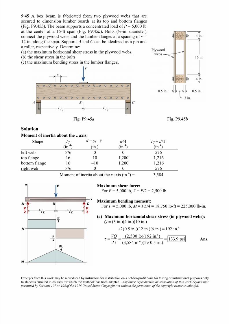
9.45 A box beam is fabricated from two plywood webs that aresecured to dimension lumber boards at its top and bottom flanges
(Fig. P9.45b). The beam supports a concentrated load of P = 5,000 lb
at the center of a 15-ft span (Fig. P9.45a). Bolts (⅜-in. diameter)connect the plywood webs and the lumber flanges at a spacing of s =
12 in. along the span. Supports A and C can be idealized as a pin and
a roller, respectively. Determine:
(a) the maximum horizontal shear stress in the plywood webs.
(b) the shear stress in the bolts.(c) the maximum bending stress in the lumber flanges.
Fig. P9.45a Fig. P9.45b
Solution
Moment of inertia about the z axis:
Shape I C d = yi – d²A I C + d²A
(in.4) (in.) (in.
4) (in.
4)
left web 576 0 0 576
top flange 16 10 1,200 1,216
bottom flange 16 –10 1,200 1,216
right web 576 0 0 576Moment of inertia about the z axis (in.
4) = 3,584
Maximum shear force:
For P = 5,000 lb, V = P /2 = 2,500 lb
Maximum bending moment:
For P = 5,000 lb, M = PL/4 = 18,750 lb-ft = 225,000 lb-in.
(a) Maximum horizontal shear stress (in plywood webs):
3
3
4
(3 in.)(4 in.)(10 in.)
2(0.5 in.)(12 in.)(6 in.) 192 in.
(2,500 lb)(192 in. )133.9 psi
(3,584 in. )(2 0.5 in.)
Q
VQ
I t τ
=
+ =
= = =×
Ans.
7/25/2019 Mechanics of Materials Solutions Chapter09 Probs38 53
http://slidepdf.com/reader/full/mechanics-of-materials-solutions-chapter09-probs38-53 12/29
Excerpts from this work may be reproduced by instructors for distribution on a not-for-profit basis for testing or instructional purposes onlyto students enrolled in courses for which the textbook has been adopted. Any other reproduction or translation of this work beyond that
permitted by Sections 107 or 108 of the 1976 United States Copyright Act without the permission of the copyright owner is unlawful.
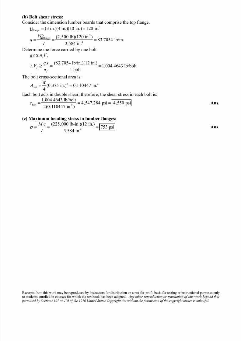
(b) Bolt shear stress:
Consider the dimension lumber boards that comprise the top flange.3
flange
3flange
4
(3 in.)(4 in.)(10 in.) 120 in.
(2,500 lb)(120 in. )83.7054 lb/in.
3,584 in.
Q
VQq
I
= =
= = =
Determine the force carried by one bolt:
(83.7054 lb/in.)(12 in.)1,004.4643 lb/bolt
1 bolt
f f
f
f
q s n V
q sV
n
≤
∴ ≥ = =
The bolt cross-sectional area is:
2 2
bolt (0.375 in.) 0.110447 in.4
A π = =
Each bolt acts in double shear; therefore, the shear stress in each bolt is:
bolt 2
1,004.4643 lb/bolt4,547.284 psi 4,550 psi
2(0.110447 in. )τ = = = Ans.
(c) Maximum bending stress in lumber flanges:
4
(225,000 lb-in.)(12 in.)753 psi
3,584 in.
M c
I σ = = = Ans.
7/25/2019 Mechanics of Materials Solutions Chapter09 Probs38 53
http://slidepdf.com/reader/full/mechanics-of-materials-solutions-chapter09-probs38-53 13/29
Excerpts from this work may be reproduced by instructors for distribution on a not-for-profit basis for testing or instructional purposes onlyto students enrolled in courses for which the textbook has been adopted. Any other reproduction or translation of this work beyond that
permitted by Sections 107 or 108 of the 1976 United States Copyright Act without the permission of the copyright owner is unlawful.
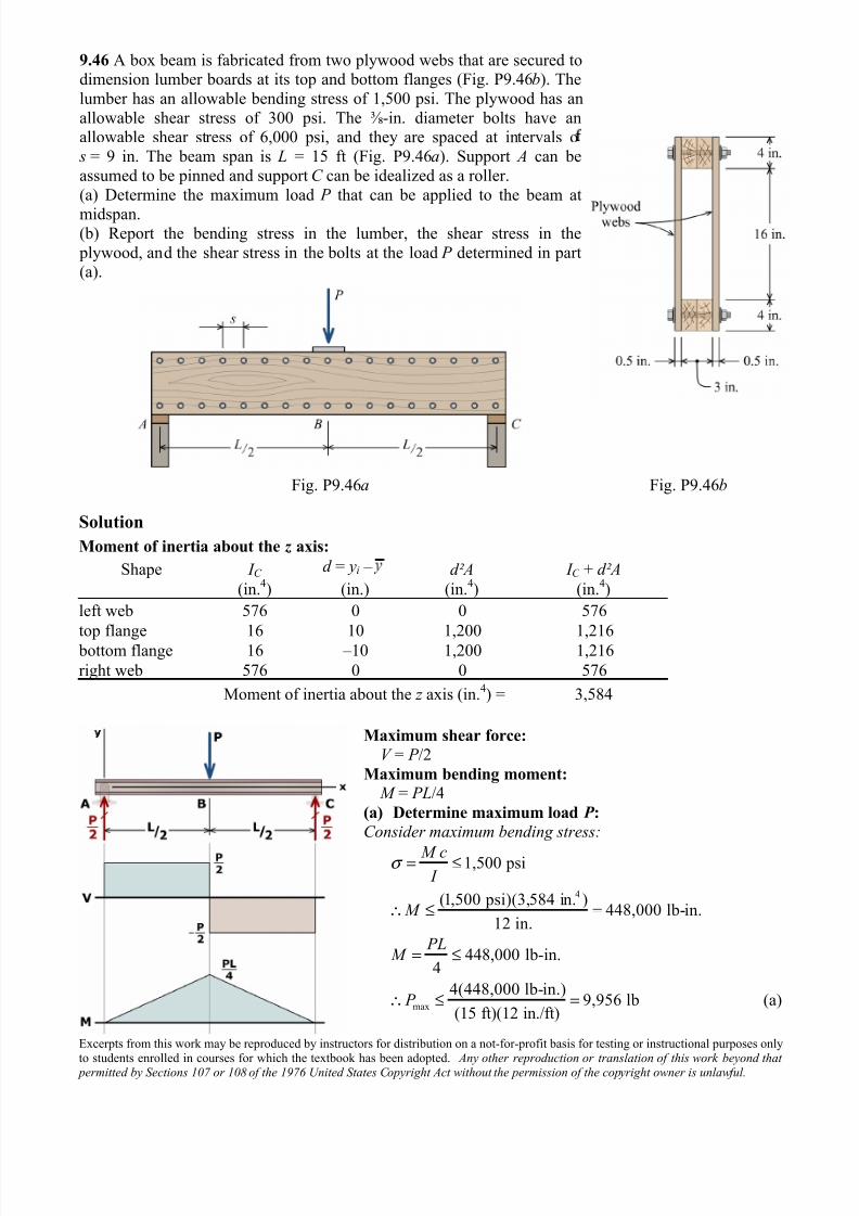
9.46 A box beam is fabricated from two plywood webs that are secured todimension lumber boards at its top and bottom flanges (Fig. P9.46b). The
lumber has an allowable bending stress of 1,500 psi. The plywood has an
allowable shear stress of 300 psi. The ⅜-in. diameter bolts have anallowable shear stress of 6,000 psi, and they are spaced at intervals o
s = 9 in. The beam span is L = 15 ft (Fig. P9.46a). Support A can be
assumed to be pinned and support C can be idealized as a roller.
(a) Determine the maximum load P that can be applied to the beam at
midspan.(b) Report the bending stress in the lumber, the shear stress in the
plywood, and the shear stress in the bolts at the load P determined in part(a).
Fig. P9.46a Fig. P9.46b
Solution
Moment of inertia about the z axis:
Shape I C d = yi – d²A I C + d²A
(in.4) (in.) (in.
4) (in.
4)
left web 576 0 0 576
top flange 16 10 1,200 1,216 bottom flange 16 –10 1,200 1,216
right web 576 0 0 576
Moment of inertia about the z axis (in.4) = 3,584
Maximum shear force:
V = P /2
Maximum bending moment:
M = PL/4
(a) Determine maximum load P :
Consider maximum bending stress:
4
1,500 psi
(1,500 psi)(3,584 in. )448,000 lb-in.
12 in.
M c I
M
σ = ≤
∴ ≤ =
max
448,000 lb-in.4
4(448,000 lb-in.)9,956 lb
(15 ft)(12 in./ft)
PL M
P
= ≤
∴ ≤ = (a)
7/25/2019 Mechanics of Materials Solutions Chapter09 Probs38 53
http://slidepdf.com/reader/full/mechanics-of-materials-solutions-chapter09-probs38-53 14/29
Excerpts from this work may be reproduced by instructors for distribution on a not-for-profit basis for testing or instructional purposes onlyto students enrolled in courses for which the textbook has been adopted. Any other reproduction or translation of this work beyond that
permitted by Sections 107 or 108 of the 1976 United States Copyright Act without the permission of the copyright owner is unlawful.
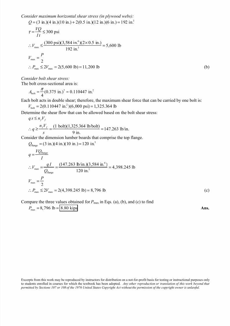
Consider maximum horizontal shear stress (in plywood webs):3
4
max 3
max
max max
(3 in.)(4 in.)(10 in.) 2(0.5 in.)(12 in.)(6 in.) 192 in.
300 psi
(300 psi)(3,584 in. )(2 0.5 in.)5,600 lb
192 in.
2
2 2(5,600 lb) 11,200 lb
Q
VQ
I t
V
P V
P V
τ
= + =
= ≤
×∴ ≤ =
=
∴ ≤ = = (b)
Consider bolt shear stress:The bolt cross-sectional area is:
2 2
bolt (0.375 in.) 0.110447 in.4
A π = =
Each bolt acts in double shear; therefore, the maximum shear force that can be carried by one bolt is:2
bolt 2(0.110447 in. )(6,000 psi) 1,325.364 lbV = =
Determine the shear flow that can be allowed based on the bolt shear stress:
(1 bolt)(1,325.364 lb/bolt)147.263 lb/in.
9 in.
f f
f f
q s n V
n V q
s
≤
∴ ≥ = =
Consider the dimension lumber boards that comprise the top flange.3
flange
flange
4
max 3
flange
max
max max
(3 in.)(4 in.)(10 in.) 120 in.
(147.263 lb/in.)(3,584 in. )4,398.245 lb
120 in.
2
2 2(4,398.245 lb) 8,796 lb
Q
VQq
I
q I V
Q P
V
P V
= =
=
∴ = = =
=
∴ ≤ = = (c)
Compare the three values obtained for P max in Eqs. (a), (b), and (c) to find
max 8,796 lb 8.80 kips P = = Ans.
7/25/2019 Mechanics of Materials Solutions Chapter09 Probs38 53
http://slidepdf.com/reader/full/mechanics-of-materials-solutions-chapter09-probs38-53 15/29
Excerpts from this work may be reproduced by instructors for distribution on a not-for-profit basis for testing or instructional purposes onlyto students enrolled in courses for which the textbook has been adopted. Any other reproduction or translation of this work beyond that
permitted by Sections 107 or 108 of the 1976 United States Copyright Act without the permission of the copyright owner is unlawful.
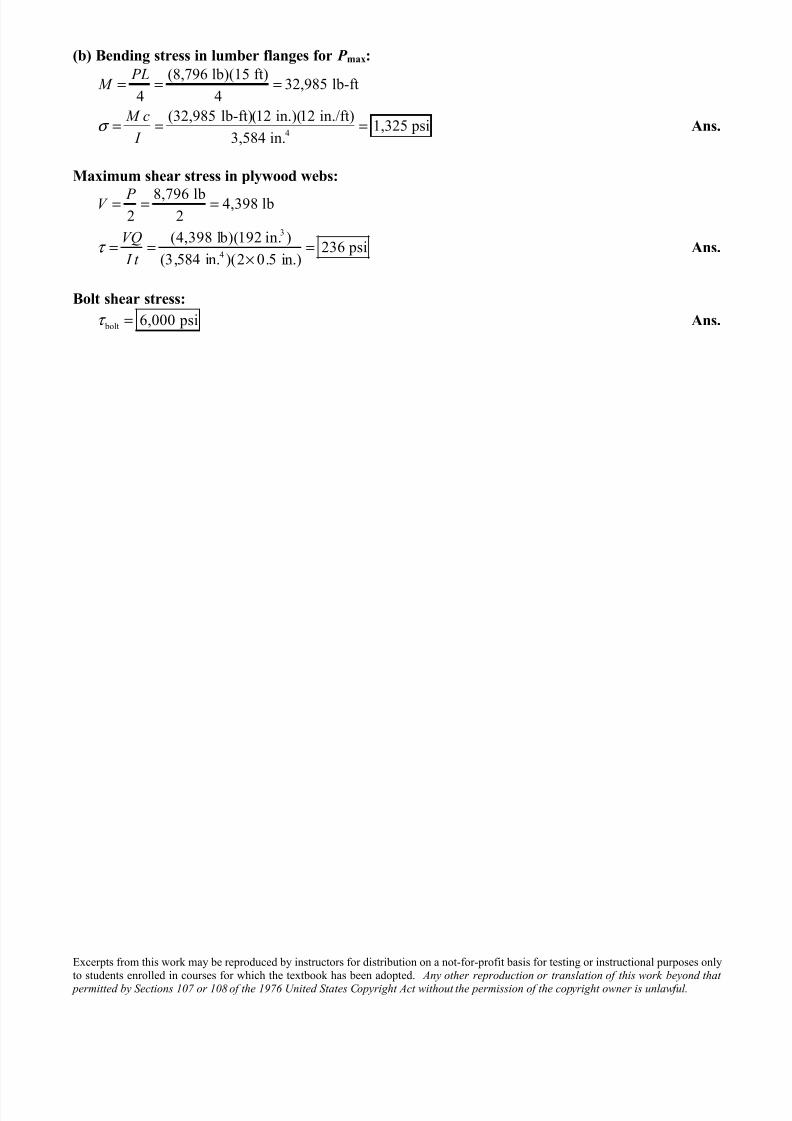
(b) Bending stress in lumber flanges for P max:
4
(8,796 lb)(15 ft)32,985 lb-ft
4 4
(32,985 lb-ft)(12 in.)(12 in./ft)1,325 psi
3,584 in.
PL M
M c
I σ
= = =
= = = Ans.
Maximum shear stress in plywood webs:
3
4
8,796 lb 4,398 lb2 2
(4,398 lb)(192 in. )236 psi
(3,584 in. )(2 0.5 in.)
P V
VQ
I t τ
= = =
= = =×
Ans.
Bolt shear stress:
bolt 6,000 psiτ = Ans.
7/25/2019 Mechanics of Materials Solutions Chapter09 Probs38 53
http://slidepdf.com/reader/full/mechanics-of-materials-solutions-chapter09-probs38-53 16/29
Excerpts from this work may be reproduced by instructors for distribution on a not-for-profit basis for testing or instructional purposes onlyto students enrolled in courses for which the textbook has been adopted. Any other reproduction or translation of this work beyond that
permitted by Sections 107 or 108 of the 1976 United States Copyright Act without the permission of the copyright owner is unlawful.
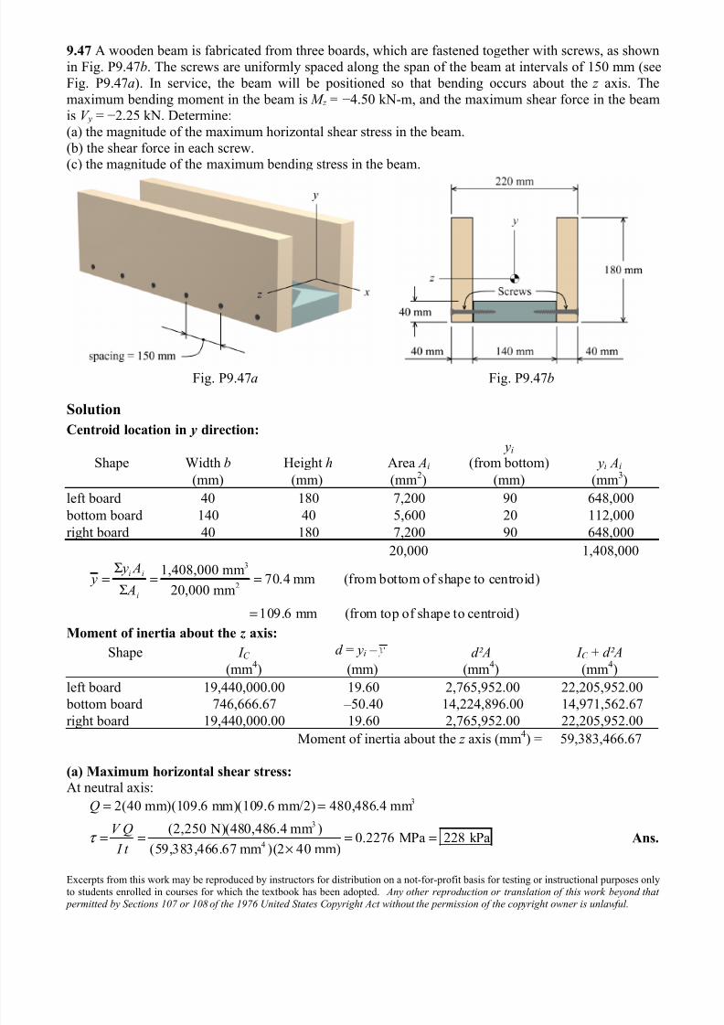
9.47 A wooden beam is fabricated from three boards, which are fastened together with screws, as shown
in Fig. P9.47b. The screws are uniformly spaced along the span of the beam at intervals of 150 mm (see
Fig. P9.47a). In service, the beam will be positioned so that bending occurs about the z axis. The
maximum bending moment in the beam is M z = −4.50 kN-m, and the maximum shear force in the beamis V y = −2.25 kN. Determine:
(a) the magnitude of the maximum horizontal shear stress in the beam.
(b) the shear force in each screw.(c) the magnitude of the maximum bending stress in the beam.
Fig. P9.47a Fig. P9.47b
Solution
Centroid location in y direction:
Shape Width b Height h Area Ai
yi (from bottom) yi Ai
(mm) (mm) (mm2) (mm) (mm3)
left board 40 180 7,200 90 648,000
bottom board 140 40 5,600 20 112,000
right board 40 180 7,200 90 648,00020,000 1,408,000
3
2
1,408,000 mm70.4 mm (from bottom of shape to centroid)
20,000 mm
109.6 mm (from top of shape to centroid)
i i
i
y A y
A
Σ= = =
Σ
=
Moment of inertia about the z axis:
Shape I C d = yi – d²A I C + d²A
(mm4) (mm) (mm
4) (mm
4)
left board 19,440,000.00 19.60 2,765,952.00 22,205,952.00
bottom board 746,666.67 –50.40 14,224,896.00 14,971,562.67
right board 19,440,000.00 19.60 2,765,952.00 22,205,952.00Moment of inertia about the z axis (mm
4) = 59,383,466.67
(a) Maximum horizontal shear stress:
At neutral axis:3
3
4
2(40 mm)(109.6 mm)(109.6 mm/2) 480,486.4 mm
(2,250 N)(480,486.4 mm )0.2276 MPa 228 kPa
(59,383,466.67 mm )(2 40 mm)
Q
V Q
I t τ
= =
= = = =×
Ans.
7/25/2019 Mechanics of Materials Solutions Chapter09 Probs38 53
http://slidepdf.com/reader/full/mechanics-of-materials-solutions-chapter09-probs38-53 17/29
Excerpts from this work may be reproduced by instructors for distribution on a not-for-profit basis for testing or instructional purposes onlyto students enrolled in courses for which the textbook has been adopted. Any other reproduction or translation of this work beyond that
permitted by Sections 107 or 108 of the 1976 United States Copyright Act without the permission of the copyright owner is unlawful.
(b) Shear force in each screw
Consider bottom board, which is held in place by two screws:3
3
4
(140 mm)(40 mm)(70.4 mm 40 mm/2) 282,240 mm
(2,250 N)(282,240 mm )10.6939 N/mm
59,383,466.67 mm
(10.6939 N/mm)(150 mm)802 N per screw
2 screws
f f
f
f
Q
V Qq
I
q s n V
q sV
n
= − =
= = =
≤
∴ = = = Ans.
(c) Maximum bending stress: 6
4
( 4.50 10 N-mm)(109.6 mm)8.31 MPa (T)
59,383,466.67 mm
z x
z
M y
I σ
− ×= − = − = Ans.
7/25/2019 Mechanics of Materials Solutions Chapter09 Probs38 53
http://slidepdf.com/reader/full/mechanics-of-materials-solutions-chapter09-probs38-53 18/29
Excerpts from this work may be reproduced by instructors for distribution on a not-for-profit basis for testing or instructional purposes onlyto students enrolled in courses for which the textbook has been adopted. Any other reproduction or translation of this work beyond that
permitted by Sections 107 or 108 of the 1976 United States Copyright Act without the permission of the copyright owner is unlawful.
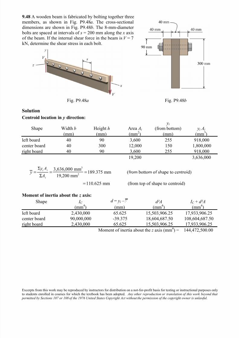
9.48 A wooden beam is fabricated by bolting together threemembers, as shown in Fig. P9.48a. The cross-sectional
dimensions are shown in Fig. P9.48b. The 8-mm-diameter
bolts are spaced at intervals of s = 200 mm along the x axisof the beam. If the internal shear force in the beam is V = 7
kN, determine the shear stress in each bolt.
Fig. P9.48a Fig. P9.48b
Solution
Centroid location in y direction:
Shape Width b Height h Area Ai
yi (from bottom) yi Ai
(mm) (mm) (mm2) (mm) (mm
3)
left board 40 90 3,600 255 918,000
center board 40 300 12,000 150 1,800,000
right board 40 90 3,600 255 918,000
19,200 3,636,000
3
2
3,636,000 mm189.375 mm (from bottom of shape to centroid)
19,200 mm110.625 mm (from top of shape to centroid)
i i
i
y A y
A
Σ= = =
Σ
=
Moment of inertia about the z axis:
Shape I C d = yi – d²A I C + d²A
(mm4) (mm) (mm
4) (mm
4)
left board 2,430,000 65.625 15,503,906.25 17,933,906.25
center board 90,000,000 -39.375 18,604,687.50 108,604,687.50
right board 2,430,000 65.625 15,503,906.25 17,933,906.25
Moment of inertia about the z axis (mm4) = 144,472,500.00
7/25/2019 Mechanics of Materials Solutions Chapter09 Probs38 53
http://slidepdf.com/reader/full/mechanics-of-materials-solutions-chapter09-probs38-53 19/29
Excerpts from this work may be reproduced by instructors for distribution on a not-for-profit basis for testing or instructional purposes onlyto students enrolled in courses for which the textbook has been adopted. Any other reproduction or translation of this work beyond that
permitted by Sections 107 or 108 of the 1976 United States Copyright Act without the permission of the copyright owner is unlawful.
Shear force in each bolt
Consider left board, which is held in place by the bolt:3
3
4
(40 mm)(90 mm)(110.625 mm 90 mm/2) 236,250 mm
(7,000 N)(236,250 mm )11.4468 N/mm
144,472,500 mm
Q
V Qq
I
= − =
= = =
Note that this value of q is the shear flow that must be transmitted by one surface of the bolt cross
section. The cross-sectional area of the bolt is:
2 2
bolt (8 mm) 50.2655 mm4
A π = =
Relate the shear flow and the bolt shear stress with Eq. (9.14):
2
(11.4468 N/mm)(200 mm)45.5 MPa
(1 bolt surface)(50.2655 mm )
f f f
f
f f
q s n A
q s
n A
τ
τ
≤
∴ = = = Ans.
7/25/2019 Mechanics of Materials Solutions Chapter09 Probs38 53
http://slidepdf.com/reader/full/mechanics-of-materials-solutions-chapter09-probs38-53 20/29
Excerpts from this work may be reproduced by instructors for distribution on a not-for-profit basis for testing or instructional purposes onlyto students enrolled in courses for which the textbook has been adopted. Any other reproduction or translation of this work beyond that
permitted by Sections 107 or 108 of the 1976 United States Copyright Act without the permission of the copyright owner is unlawful.
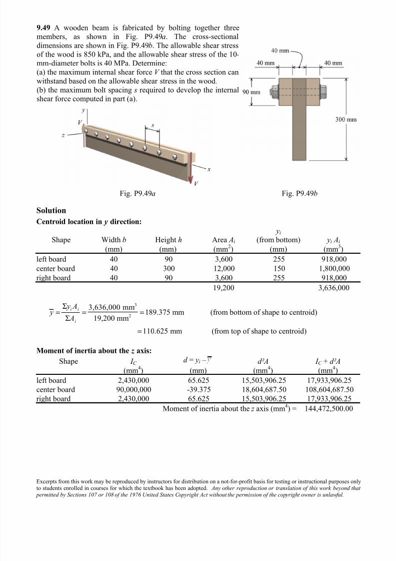
9.49 A wooden beam is fabricated by bolting together threemembers, as shown in Fig. P9.49a. The cross-sectional
dimensions are shown in Fig. P9.49b. The allowable shear stress
of the wood is 850 kPa, and the allowable shear stress of the 10-mm-diameter bolts is 40 MPa. Determine:
(a) the maximum internal shear force V that the cross section can
withstand based on the allowable shear stress in the wood.
(b) the maximum bolt spacing s required to develop the internal
shear force computed in part (a).
Fig. P9.49a Fig. P9.49b
Solution
Centroid location in y direction:
Shape Width b Height h Area Ai
yi (from bottom) yi Ai
(mm) (mm) (mm2) (mm) (mm
3)
left board 40 90 3,600 255 918,000
center board 40 300 12,000 150 1,800,000
right board 40 90 3,600 255 918,000
19,200 3,636,000
3
2
3,636,000 mm189.375 mm (from bottom of shape to centroid)
19,200 mm
110.625 mm (from top of shape to centroid)
i i
i
y A y
A
Σ= = =
Σ
=
Moment of inertia about the z axis:
Shape I C d = yi – d²A I C + d²A
(mm4) (mm) (mm
4) (mm
4)
left board 2,430,000 65.625 15,503,906.25 17,933,906.25
center board 90,000,000 -39.375 18,604,687.50 108,604,687.50right board 2,430,000 65.625 15,503,906.25 17,933,906.25
Moment of inertia about the z axis (mm4) = 144,472,500.00
7/25/2019 Mechanics of Materials Solutions Chapter09 Probs38 53
http://slidepdf.com/reader/full/mechanics-of-materials-solutions-chapter09-probs38-53 21/29
Excerpts from this work may be reproduced by instructors for distribution on a not-for-profit basis for testing or instructional purposes onlyto students enrolled in courses for which the textbook has been adopted. Any other reproduction or translation of this work beyond that
permitted by Sections 107 or 108 of the 1976 United States Copyright Act without the permission of the copyright owner is unlawful.
Consider maximum horizontal shear stress:3
2 4
max 3
(40 mm)(189.375 mm)(189.375 mm/2) 717,257.813 mm
850 kPa 0.850 MPa
(0.850 N/mm )(144,472,500 mm )(40 mm)6,848.4 N 6.85 kN
717,257.813 mm
Q
VQ
I t
V
τ
= =
= ≤ =
∴ ≤ = = Ans.
Maximum bolt spacing
Consider left board, which is held in place by the bolt:3
3
4
(40 mm)(90 mm)(110.625 mm 90 mm/2) 236,250 mm
(6,848.4 N)(236,250 mm )11.1989 N/mm
144,472,500 mm
Q
V Qq
I
= − =
= = =
Note that this value of q is the shear flow that must be transmitted by one surface of the bolt cross
section. The cross-sectional area of the bolt is:
2 2
bolt (10 mm) 78.5398 mm
4
A π = =
Relate the shear flow and the bolt shear stress with Eq. (9.14):
2 2(1 bolt surface)(40 N/mm )(78.5398 mm )281 mm
11.1989 N/mm
f f f
f f f
q s n A
n A s
q
τ
τ
≤
∴ ≤ = = Ans.
7/25/2019 Mechanics of Materials Solutions Chapter09 Probs38 53
http://slidepdf.com/reader/full/mechanics-of-materials-solutions-chapter09-probs38-53 22/29
Excerpts from this work may be reproduced by instructors for distribution on a not-for-profit basis for testing or instructional purposes onlyto students enrolled in courses for which the textbook has been adopted. Any other reproduction or translation of this work beyond that
permitted by Sections 107 or 108 of the 1976 United States Copyright Act without the permission of the copyright owner is unlawful.
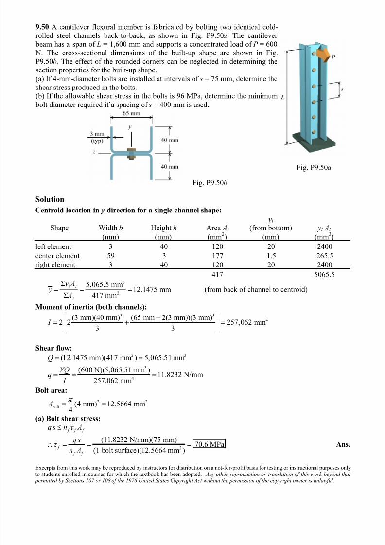
9.50 A cantilever flexural member is fabricated by bolting two identical cold-rolled steel channels back-to-back, as shown in Fig. P9.50a. The cantilever
beam has a span of L = 1,600 mm and supports a concentrated load of P = 600
N. The cross-sectional dimensions of the built-up shape are shown in Fig.P9.50b. The effect of the rounded corners can be neglected in determining the
section properties for the built-up shape.
(a) If 4-mm-diameter bolts are installed at intervals of s = 75 mm, determine the
shear stress produced in the bolts.
(b) If the allowable shear stress in the bolts is 96 MPa, determine the minimum bolt diameter required if a spacing of s = 400 mm is used.
Fig. P9.50b
Fig. P9.50a
Solution
Centroid location in y direction for a single channel shape:
Shape Width b Height h Area Ai
yi (from bottom) yi Ai
(mm) (mm) (mm2) (mm) (mm
3)
left element 3 40 120 20 2400
center element 59 3 177 1.5 265.5
right element 3 40 120 20 2400
417 5065.53
25,065.5 mm 12.1475 mm (from back of channel to centroid)
417 mmi i
i
y A y A
Σ= = =
Σ
Moment of inertia (both channels):3 3
4(3 mm)(40 mm) (65 mm 2(3 mm))(3 mm)2 2 257,062 mm
3 3 I
⎡ ⎤−= + =⎢ ⎥
⎣ ⎦
Shear flow:2 3
3
4
(12.1475 mm)(417 mm ) 5,065.51 mm
(600 N)(5,065.51 mm )11.8232 N/mm
257,062 mm
Q
VQq
I
= =
= = =
Bolt area:
2 2
bolt (4 mm) 12.5664 mm4
A π = =
(a) Bolt shear stress:
2
(11.8232 N/mm)(75 mm)70.6 MPa
(1 bolt surface)(12.5664 mm )
f f f
f
f f
q s n A
q s
n A
τ
τ
≤
∴ = = = Ans.
7/25/2019 Mechanics of Materials Solutions Chapter09 Probs38 53
http://slidepdf.com/reader/full/mechanics-of-materials-solutions-chapter09-probs38-53 23/29
Excerpts from this work may be reproduced by instructors for distribution on a not-for-profit basis for testing or instructional purposes onlyto students enrolled in courses for which the textbook has been adopted. Any other reproduction or translation of this work beyond that
permitted by Sections 107 or 108 of the 1976 United States Copyright Act without the permission of the copyright owner is unlawful.
(b) Minimum bolt diameter for s = 400 mm:
2
2
2 2
bolt
2
bolt
(11.8232 N/mm)(400 mm)49.2633 mm
(1 bolt surface)(96 N/mm )
49.2633 mm4
4(49.2633 mm )7.92 mm
f f f
f
f f
q s n A
q s A
n
A D
D
τ
τ
π
π
≤
∴ ≥ = =
= ≥
≥ = Ans.
7/25/2019 Mechanics of Materials Solutions Chapter09 Probs38 53
http://slidepdf.com/reader/full/mechanics-of-materials-solutions-chapter09-probs38-53 24/29
Excerpts from this work may be reproduced by instructors for distribution on a not-for-profit basis for testing or instructional purposes onlyto students enrolled in courses for which the textbook has been adopted. Any other reproduction or translation of this work beyond that
permitted by Sections 107 or 108 of the 1976 United States Copyright Act without the permission of the copyright owner is unlawful.
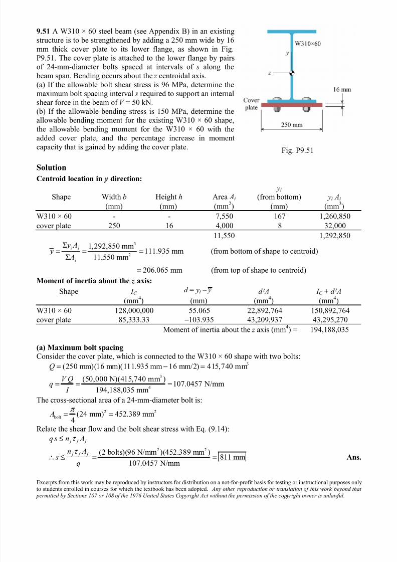
9.51 A W310 × 60 steel beam (see Appendix B) in an existing
structure is to be strengthened by adding a 250 mm wide by 16
mm thick cover plate to its lower flange, as shown in Fig.
P9.51. The cover plate is attached to the lower flange by pairsof 24-mm-diameter bolts spaced at intervals of s along the
beam span. Bending occurs about the z centroidal axis.
(a) If the allowable bolt shear stress is 96 MPa, determine themaximum bolt spacing interval s required to support an internal
shear force in the beam of V = 50 kN.
(b) If the allowable bending stress is 150 MPa, determine theallowable bending moment for the existing W310 × 60 shape,
the allowable bending moment for the W310 × 60 with the
added cover plate, and the percentage increase in moment
capacity that is gained by adding the cover plate. Fig. P9.51
Solution
Centroid location in y direction:
Shape Width b Height h Area Ai
yi
(from bottom) yi Ai
(mm) (mm) (mm2) (mm) (mm
3)
W310 × 60 - - 7,550 167 1,260,850
cover plate 250 16 4,000 8 32,000
11,550 1,292,8503
2
1,292,850 mm111.935 mm (from bottom of shape to centroid)
11,550 mm
206.065 mm (from top of shape to centroid)
i i
i
y A y
A
Σ= = =
Σ
=
Moment of inertia about the z axis:
Shape I C d = yi –
d²A I C + d²A (mm4) (mm) (mm
4) (mm
4)
W310 × 60 128,000,000 55.065 22,892,764 150,892,764
cover plate 85,333.33 –103.935 43,209,937 43,295,270
Moment of inertia about the z axis (mm4) = 194,188,035
(a) Maximum bolt spacing
Consider the cover plate, which is connected to the W310 × 60 shape with two bolts:3
3
4
(250 mm)(16 mm)(111.935 mm 16 mm/2) 415,740 mm
(50,000 N)(415,740 mm )107.0457 N/mm
194,188,035 mm
Q
V Qq
I
= − =
= = =
The cross-sectional area of a 24-mm-diameter bolt is:
2 2
bolt (24 mm) 452.389 mm4
A π = =
Relate the shear flow and the bolt shear stress with Eq. (9.14):
2 2(2 bolts)(96 N/mm )(452.389 mm )811 mm
107.0457 N/mm
f f f
f f f
q s n A
n A s
q
τ
τ
≤
∴ ≤ = = Ans.
7/25/2019 Mechanics of Materials Solutions Chapter09 Probs38 53
http://slidepdf.com/reader/full/mechanics-of-materials-solutions-chapter09-probs38-53 25/29
Excerpts from this work may be reproduced by instructors for distribution on a not-for-profit basis for testing or instructional purposes onlyto students enrolled in courses for which the textbook has been adopted. Any other reproduction or translation of this work beyond that
permitted by Sections 107 or 108 of the 1976 United States Copyright Act without the permission of the copyright owner is unlawful.
(b) Allowable bending moment for W310 × 60 shape (without cover plate):
2 4
allow
150 MPa
(150 N/mm )(128,000,000 mm )127,152,318 N-mm 127.2 kN-m
(302 mm/2)
M c
I
M
σ = ≤
∴ = = = Ans.
Allowable bending moment for W310 × 60 shape (with cover plate):
2 4
allow
150 MPa
(150 N/mm )(194,188,035 mm )141,354,452 N-mm 141.4 kN-m
(206.065 mm)
M c I
M
σ = ≤
∴ = = = Ans.
Percentage increase in moment capacity:
141,354,452 N-mm 127,152,318 N-mm% increase (100%) 11.17%
127,152,318 N-mm
−= = Ans.
7/25/2019 Mechanics of Materials Solutions Chapter09 Probs38 53
http://slidepdf.com/reader/full/mechanics-of-materials-solutions-chapter09-probs38-53 26/29
Excerpts from this work may be reproduced by instructors for distribution on a not-for-profit basis for testing or instructional purposes onlyto students enrolled in courses for which the textbook has been adopted. Any other reproduction or translation of this work beyond that
permitted by Sections 107 or 108 of the 1976 United States Copyright Act without the permission of the copyright owner is unlawful.
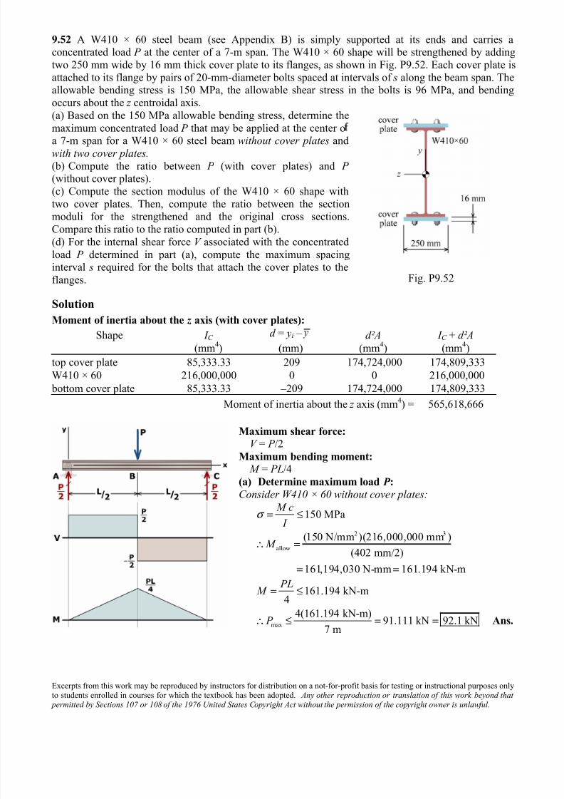
9.52 A W410 × 60 steel beam (see Appendix B) is simply supported at its ends and carries aconcentrated load P at the center of a 7-m span. The W410 × 60 shape will be strengthened by adding
two 250 mm wide by 16 mm thick cover plate to its flanges, as shown in Fig. P9.52. Each cover plate is
attached to its flange by pairs of 20-mm-diameter bolts spaced at intervals of s along the beam span. Theallowable bending stress is 150 MPa, the allowable shear stress in the bolts is 96 MPa, and bending
occurs about the z centroidal axis.
(a) Based on the 150 MPa allowable bending stress, determine the
maximum concentrated load P that may be applied at the center o
a 7-m span for a W410 × 60 steel beam without cover plates andwith two cover plates.
(b) Compute the ratio between P (with cover plates) and P (without cover plates).
(c) Compute the section modulus of the W410 × 60 shape with
two cover plates. Then, compute the ratio between the sectionmoduli for the strengthened and the original cross sections.
Compare this ratio to the ratio computed in part (b).
(d) For the internal shear force V associated with the concentrated
load P determined in part (a), compute the maximum spacinginterval s required for the bolts that attach the cover plates to the
flanges. Fig. P9.52
Solution
Moment of inertia about the z axis (with cover plates):
Shape I C d = yi – d²A I C + d²A
(mm4) (mm) (mm
4) (mm
4)
top cover plate 85,333.33 209 174,724,000 174,809,333
W410 × 60 216,000,000 0 0 216,000,000
bottom cover plate 85,333.33 –209 174,724,000 174,809,333
Moment of inertia about the z axis (mm4) = 565,618,666
Maximum shear force:
V = P /2
Maximum bending moment:
M = PL/4
(a) Determine maximum load P :
Consider W410 × 60 without cover plates:
150 MPa M c
I σ = ≤
2 3
allow
(150 N/mm )(216,000,000 mm )
(402 mm/2)
161,194,030 N-mm 161.194 kN-m
M ∴ =
= =
max
161.194 kN-m4
4(161.194 kN-m)91.111 kN 92.1 kN
7 m
PL M
P
= ≤
∴ ≤ = = Ans.
7/25/2019 Mechanics of Materials Solutions Chapter09 Probs38 53
http://slidepdf.com/reader/full/mechanics-of-materials-solutions-chapter09-probs38-53 27/29
Excerpts from this work may be reproduced by instructors for distribution on a not-for-profit basis for testing or instructional purposes onlyto students enrolled in courses for which the textbook has been adopted. Any other reproduction or translation of this work beyond that
permitted by Sections 107 or 108 of the 1976 United States Copyright Act without the permission of the copyright owner is unlawful.
Consider W410 × 60 with two cover plates:
150 MPa M c
I σ = ≤
2 3
allow
(150 N/mm )(565,618,666 mm )390,980,645 N-mm 390.981 kN-m
(434 mm/2) M ∴ = = =
max
390.981 kN-m4
4(390.981 kN-m)223.418 kN 223 kN
7 m
PL M
P
= ≤
∴ ≤ = = Ans.
(b) Ratio
(with cover plates) 223.418 kNratio 2.43
(without cover plates) 91.111 kN
P
P = = = Ans.
(c) Section moduli comparison
Section modulus of W410 × 60 without cover plates:
S = 1,060,000 mm3
Section modulus of W410 × 60 with two cover plates:4
3
3
3
565,618,666 mm2,606,538 mm
(434 mm/2)
2,606,538 mmratio 2.46
1,060,000 mm
I S
c= = =
= = Ans.
7/25/2019 Mechanics of Materials Solutions Chapter09 Probs38 53
http://slidepdf.com/reader/full/mechanics-of-materials-solutions-chapter09-probs38-53 28/29
Excerpts from this work may be reproduced by instructors for distribution on a not-for-profit basis for testing or instructional purposes onlyto students enrolled in courses for which the textbook has been adopted. Any other reproduction or translation of this work beyond that
permitted by Sections 107 or 108 of the 1976 United States Copyright Act without the permission of the copyright owner is unlawful.
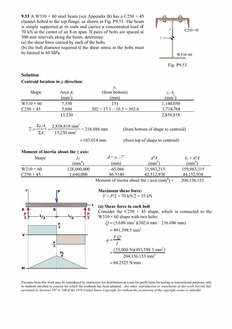
9.53 A W310 × 60 steel beam (see Appendix B) has a C250 × 45channel bolted to the top flange, as shown in Fig. P9.53. The beam
is simply supported at its ends and carries a concentrated load o
70 kN at the center of an 8-m span. If pairs of bolts are spaced at500-mm intervals along the beam, determine:
(a) the shear force carried by each of the bolts.
(b) the bolt diameter required if the shear stress in the bolts must
be limited to 60 MPa.
Fig. P9.53
Solution
Centroid location in y direction:
Shape Area Ai
yi (from bottom) yi Ai
(mm2) (mm) (mm
3)
W310 × 60 7,550 151 1,140,050
C250 × 45 5,680 302 + 17.1 – 16.5 = 302.6 1,718,768
13,230 2,858,818
3
2
2,858,818 mm216.086 mm (from bottom of shape to centroid)
13,230 mm
103.014 mm (from top of shape to centroid)
i i
i
y A y
A
Σ= = =
Σ
=
Moment of inertia about the z axis:
Shape I C d = yi – d²A I C + d²A
(mm4) (mm) (mm
4) (mm
4)
W310 × 60 128,000,000 –65.086 31,983,215 159,983,315
C250 × 45 1,640,000 86.5140 42,512,938 44,152,938
Moment of inertia about the z axis (mm4) = 204,136,153
Maximum shear force:
V = P /2 = 70 kN/2 = 35 kN
(a) Shear force in each bolt
Consider the C250 × 45 shape, which is connected to the
W310 × 60 shape with two bolts:2
3
3
4
(5,680 mm )(302.6 mm 216.086 mm)
491,399.5 mm
(35,000 N)(491,399.5 mm )
204,136,153 mm
84.2525 N/mm
Q
V Qq
I
= −
=
=
=
=
7/25/2019 Mechanics of Materials Solutions Chapter09 Probs38 53
http://slidepdf.com/reader/full/mechanics-of-materials-solutions-chapter09-probs38-53 29/29
Relate the shear flow and the bolt shear force with Eq. (9.13):
(84.2525 N/mm)(500 mm)21,063 N 21.1 kN per bolt
2 bolts
f f
f
f
q s n V
q sV
n
≤
∴ ≤ = = = Ans.
(b) Required bolt diameter
2 bolt bolt
bolt 2 bolt allow
2 2
bolt bolt
2
bolt
21,063 N
351.052 mm60 N/mm
351.052 mm4
4(351.052 mm )21.1 mm
V V
A A
A D
D
τ
τ
π
π
≥ ∴ ≥ = =
= ≥
∴ ≥ = Ans.


![Chapter09[1] Strategy Evaluation](https://img.pdfslide.net/doc/110x75/55cf9a4f550346d033a13099/chapter091-strategy-evaluation.jpg)