Embed Size (px)
Citation preview
Chaofeng LuDepartment of Civil Engineering and
Soft Matter Research Center,
Zhejiang University,
Hangzhou 310058, China;
Department of Civil and Environmental
Engineering and Mechanical Engineering,
Northwestern University,
Evanston, IL 60208
Ming LiDepartment of Civil and Environmental
Engineering and Mechanical Engineering,
Northwestern University,
Evanston, IL 60208;
State Key Laboratroy of
Structural Analysis for Industrial Equipment,
Dalian University of Technology,
Dalian 116024, China
Jianliang Xiao1
Department of Mechanical Engineering,
University of Colorado,
Boulder, CO 80309
e-mail: [email protected]
Inhwa JungDepartment of Mechanical Engineering,
Kyung Hee University,
Seocheon-dong, Giheung-gu,
Yongin-si, Gyoenggi-do 446-701, Korea
Jian WuDepartment of Engineering Mechanics,
Tsinghua University,
Beijing 100084, China;
Center for Mechanics and Materials,
Tsinghua University,
Beijing 100084, China
Yonggang HuangDepartment of Civil and Environmental
Engineering and Mechanical Engineering,
Northwestern University,
Evanston, IL 60208
Keh-Chih HwangDepartment of Engineering Mechanics,
Tsinghua University,
Beijing 100084, China;
Center for Mechanics and Materials,
Tsinghua University,
Beijing 100084, China
John A. RogersDepartment of Materials
Science and Engineering,
Beckman Institute, and Materials
Research Laboratory,
University of Illinois,
Urbana, IL 61801
Mechanics of TunableHemispherical Electronic EyeCamera Systems That CombineRigid Device Elements With SoftElastomersA tunable hemispherical imaging system with zoom capability was recently developed byexploiting heterogeneous integration of rigid silicon photodetectors on soft, elastomericsupports, in designs that can facilitate tunable curvature for both the lens and detector.This paper reports analytical mechanics models for the soft materials aspects of the tuna-ble lenses and detector surfaces used in such devices. The results provide analyticalexpressions for the strain distributions, apex heights and detector positions, and havebeen validated by the experiments and finite element analysis. More broadly, they repre-sent important design tools for advanced cameras that combine hard and soft materialsinto nonplanar layouts with adjustable geometries. [DOI: 10.1115/1.4023962]
Keywords: tunable electronic eye camera, hyperelastic material, finite strain, pressure-deflection relation, analytical solution
1Corresponding author.Manuscript received December 19, 2012; final manuscript received February 12,
2013; accepted manuscript posted March 6, 2013; published online August 21, 2013.Assoc. Editor: Huajian Gao.
Journal of Applied Mechanics NOVEMBER 2013, Vol. 80 / 061022-1Copyright VC 2013 by ASME
Downloaded From: http://appliedmechanics.asmedigitalcollection.asme.org/ on 09/02/2013 Terms of Use: http://asme.org/terms
1 Introduction
Conventional digital cameras use arrays of photodetectors inplanar layouts; this configuration requires systems of lenses ca-pable of producing images with similar geometries, thereby plac-ing stringent constraints on engineering options, in ways that canaffect cost, size, weight, and performance. Mammalian eyes pro-vide the inspiration for alternative approaches that use curvedarrays of photodetectors with geometries to match the shapes ofimages that form with simple, compact, low cost lenses [1–4].Resolution scaling analyses and optical modeling [5] provide cri-teria for designs in such systems. Ko et al. [6] demonstrated afirst, fully functional hemispherical imaging system, with config-uration matched to the strongly nonplanar image surfaces (i.e.,Petzval surfaces) that form with single-component, plano-con-vex lenses. Such “eyeball” cameras rely critically on silicon pho-todetectors, interconnected in mesh layouts, and supported bysoft, elastomeric substrates. The result is a heterogeneous systemof hard and soft materials that can be reshaped into any desiredgeometry, based on purely elastic deformations. In the firstreported embodiments, the detector curvature was fixed [3,6],thereby rendering the cameras incompatible with changes in thenonplanar image surfaces that result from adjustable zoom.Removing this limitation requires the curvature of the detectorarray to change in a precise manner coordinated with the magni-fication setting, to ensure identical shapes for the image and de-tector surfaces at all zoom settings. Jung et al. [7] developed atunable hemispherical imaging system that provides this functionby using hydraulic actuation [8,9]. Here, an interconnected arrayof silicon photodetectors on a thin elastomeric membrane pro-vides tunable access to a range of hemispherical shapes. Com-bining such a detector with a tunable lens, also controlled byfluid pressure, yields a hemispherical camera capable of adjusta-ble zoom and excellent imaging characteristics. Such technologycould be useful for night-vision surveillance, endoscopic imag-ing, and other areas that require compact cameras with simplezoom optics and wide angle fields of view. Related curvilinearelectronic systems have been extended to other complex layouts[10,11], all of which provide function and modes of use that lieoutside of the scope of possibilities provided by conventional,planar designs.
Mechanics models of these hard/soft material systems provideimportant insights into the design and fabrication of structureswith fixed curvature [12,13]. The maximum strain in devices andtheir positions on a curvilinear surface can be determined analyti-cally, and agree well with experiments [6,10,11] and with the fi-nite element analysis (FEA) [12,13] without any parameter fitting.The objective of this paper is to establish related models and pres-ent a simple, analytical scaling relation between the overall defor-mation and applied pressure for tunable hemispherical imagingsystems that offer adjustable zoom capabilities [7]. The resultsgive analytically the curvatures of the lenses and detector arraysin terms of the fluid pressures, the corresponding maximumstrains, and the detector positions on the tunable hemisphericalsurfaces. The outcomes are shown to be consistent with both theexperiment and FEA.
The analytical results obtained by this study have importantimplications in real applications. In the tunable hemisphericalimaging system, operation of the tunable electronic eye camerasystem requires coordinated tuning of geometries of both the lensand detector due to the intrinsic optics, while our analytical solu-tions can provide a very convenient tool for this purpose. Duringthe image processing stage, analytical results can offer muchfaster means than finite element simulations for tracking pixelpositions on the dynamically changing detector surface. This isespecially important when the device is further improved for realapplications and fast image processing capability is very critical.In addition, when the tunable strategy is used in other devices andsystems, the analytical results can offer convenient and efficienttools for design and optimization.
2 Mechanics of Tunable Lens
2.1 Constitutive Model of PDMS Lens. Both the lenses andthe photodetector arrays use the elastomer poly(dimethylsiloxane)(PDMS) as the soft material component. The stress–strain relationin PDMS is characterized by the hyperelastic model for incom-pressible materials [14] with the strain energy density
W ¼X3
k¼1
Ck I1 � 3ð Þk (2.1)
which is a function of I1 ¼ k21 þ k2
2 þ k23, where k1, k2, and k3 are
the principal stretches (and k1k2k3¼ 1 due to incompressibility),and the constants Ck are to be determined from experiments. Forsimple tension along direction X1, the principal stretches arerelated to the nominal strain e by k1 ¼ k ¼ 1þ e andk2 ¼ k3 ¼ 1=
ffiffiffikp
. For W in Eq. (2.1), the Cauchy stresses aregiven by [15]
r1 ¼ 2k21
dW
dI1
þ ph ¼ 2k2X3
k¼1
kCk I1 � 1ð Þk�1 þ ph
r2 ¼ r3 ¼ 2k22
dW
dI1
þ ph ¼2
k
X3
k¼1
kCk I1 � 1ð Þk�1 þ ph
(2.2)
where I1 ¼ k2 þ 2=kð Þ, and ph is the hydrostatic pressure and isdetermined from the condition of simple tension r2 ¼ r3 ¼ 0 asph ¼ � 2=kð ÞdW=dI1. The uniaxial stress r¼ r1 is then given by
r ¼ 2 k2 � 1
k
� �dW
dI1
¼ 2 k2 � 1
k
� �C1 þ 2C2 I1 � 3ð Þ þ 3C3 I1 � 3ð Þ2h i
(2.3)
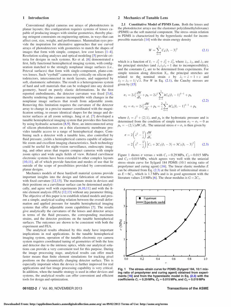
Figure 1 shows r versus e with C1¼ 0.29 MPa, C2¼ 0.015 MPaand C3¼ 0.019 MPa, which agrees very well with the uniaxialstress–strain curve for Sylgard 184 PDMS (10:1 mixing ratio ofprepolymer and curing agent) [16]. The linear elastic modulus Ecan be obtained from Eq. (2.3) at the limit of infinitesimal strain eas E¼ 6C1, which is 1.7 MPa and is in good agreement with theliterature values 2.0 MPa [6]. The shear modulus is G¼ 2C1.
Fig. 1 The stress–strain curve for PDMS (Sylgard 184, 10:1 mix-ing ratio of prepolymer and curing agent) obtained from experi-ments [16] and from the hyperelastic model in Eq. (2.3) with thecoefficients C1 5 0.29 MPa, C2 5 0.015 MPa, and C3 5 0.019 MPa
061022-2 / Vol. 80, NOVEMBER 2013 Transactions of the ASME
Downloaded From: http://appliedmechanics.asmedigitalcollection.asme.org/ on 09/02/2013 Terms of Use: http://asme.org/terms
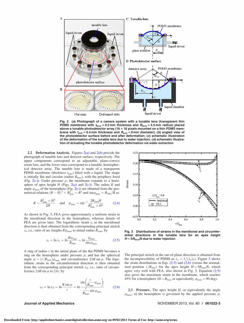
2.2 Deformation Analysis. Figures 2(a) and 2(b) provide thephotograph of tunable lens and detector surface, respectively. Theupper components correspond to an adjustable, plano-convexzoom lens, and the lower ones correspond to a tunable, hemispher-ical detector array. The tunable lens is made of a transparentPDMS membrane (thickness tlens) filled with a liquid. The shapeis initially flat and circular (radius Rlens), with the periphery fixed(Fig. 2(c)). Under pressure p, the membrane expands to a hemi-sphere of apex height H (Figs. 2(a) and 2(c)). The radius R andangle umax of the hemisphere (Fig. 2(c)) are obtained from the geo-metrical relations R� Hð Þ2þ R2
lens ¼ R2 and sinumax ¼ Rlens=R as
R ¼ R2lens þ H2
2Hand umax ¼ sin�1 2RlensH
R2lens þ H2
(2.4)
As shown in Fig. 3, FEA gives approximately a uniform strain inthe meridional direction in the hemisphere, whereas details ofFEA are given later. The logarithmic strain er in the meridionaldirection is then obtained from the corresponding principal stretchkr, i.e., ratio of arc lengths Rumax to initial radius Rlens, by
er ¼ ln kr ¼ lnRumax
Rlens
¼ lnumax
sin umax
(2.5)
A ring of radius r in the initial plane of the flat PDMS becomes aring on the hemisphere under pressure p, and has the sphericalangle u ¼ r=Rlensð Þumax and circumference 2pR sin u. The loga-rithmic strain in the circumferential direction is then obtainedfrom the corresponding principal stretch kh, i.e., ratio of circum-ference 2pR sin u to 2pr, by
eh ¼ ln kh ¼ lnR sin u
r¼ ln
sinr
Rlens
umax
� �r
Rlens
sin umax
(2.6)
The principal stretch in the out-of-plane direction is obtained fromthe incompressibility of PDMS as kz ¼ 1= krkhð Þ. Figure 3 showsthe strain distributions in Eqs. (2.5) and (2.6) (versus the normal-ized position r=Rlens) for the apex height H¼ 5Rlens/8, whichagree very well with FEA, also shown in Fig. 3. Equation (2.5)also gives the maximum strain in the membrane, which reaches45% for a hemisphere (H¼Rlens or equivalently umax¼ 90 deg).
2.3 Pressure. The apex height H, or equivalently the angleumax, of the hemisphere is governed by the applied pressure p,
Fig. 2 (a) Photograph of a camera system with a tunable lens (transparent thinPDMS membrane with tlens 5 0.2 mm thickness and Rlens 5 4.5 mm radius) placedabove a tunable photodetector array (16 3 16 pixels mounted on a thin PDMS mem-brane with tsub 5 0.4 mm thickness and Rsub 5 8 mm diameter); (b) angled view ofthe photodetector surface before and after deformation; (c) schematic illustrationof the deformation of the tunable lens due to water injection; (d) schematic illustra-tion of actuating the tunable photodetector deformation via water extraction
Fig. 3 Distributions of strains in the meridional and circumfer-ential directions in the tunable lens for an apex heightH 5 5Rlens/8 due to water injection
Journal of Applied Mechanics NOVEMBER 2013, Vol. 80 / 061022-3
Downloaded From: http://appliedmechanics.asmedigitalcollection.asme.org/ on 09/02/2013 Terms of Use: http://asme.org/terms
which is the internal fluid pressure subtracted by the atmosphericpressure and is positive. Their relation is obtained analytically inthe following.
The strain energy is the integration of W in Eq. (2.1) over thevolume V of the hemisphere
ðV
WdV ¼ 2ptlens
ðRlens
0
X3
k¼1
Ck I1 � 3ð Þkrdr
¼ 2pR2lenstlens
ð1
0
X3
k¼1
Ck I1 � 3ð Þk�rd�r (2.7)
where �r ¼ r=Rlens, and
I1 ¼u2
max
sin2 umax
þ sin2 �rumaxð Þ�r2 sin2 umax
þ �r2 sin4 umax
u2max sin2 �rumaxð Þ
(2.8)
The variation of strain energy is 2pR2lenstlens
Ð 1
0P3k¼1 kCk I1 � 3ð Þk�1@I1=@umax�rd�rdumax, which equals to the vir-
tual work done by the applied pressure, pd p=6 3R2lensH þ H3
� �� �¼ ðp=2Þp R2
lens þ H2� �
dH, where p=6 3R2lensH þ H3
� �is the vol-
ume of the hemisphere, and dH is related to dumax via Eq. (2.4).These give the applied pressure, normalized by Gtlens/Rlens, interms of umax as
pRlens
Gtlens
¼ 1þ cos umaxð Þ2ð1
0
X3
k¼1
kCk
C1
I1 � 3ð Þk�1 @I1
@umax
�rd�r (2.9)
where G¼ 2C1 is the shear modulus. The normalized apex heightH/Rlens is related to umax via Eq. (2.4), and therefore depends onlyon the normalized pressure pRlens/(Gtlens) (and C2/C1 and C3/C1).
2.4 Prestrain. Fabrication of the membrane and its integra-tion onto the stage (Fig. 2(c)) involves a compressive prestrain e0
(e.g., �2% in the experiment) prior to the applied pressure [7].For the membrane with radius Rlens on the stage, the natural radiusprior to prestrain is Rlens= 1þ e0ð Þ. The principal stretches,accounting for the effect of prestrain, are
kr ¼Rumax
Rlens= 1þ e0ð Þ ¼ 1þ e0ð Þ umax
sin umax
kh ¼R sin u
r= 1þ e0ð Þ ¼ 1þ e0ð Þsin
r
Rlens
umax
� �r
Rlens
sin umax
(2.10)
and kz ¼ 1= krkhð Þ. The applied pressure in Eq. (2.9) becomes
pRlens
Gtlens
¼ 1þ cos umax
1þ e0
� �2ð1
0
X3
k¼1
kCk
C1
I1 � 3ð Þk�1 @I1
@umax
�rd�r
(2.11)
where
I1¼ 1þe0ð Þ2 u2max
sin2 umax
þsin2 �rumaxð Þ�r2 sin2 umax
þ �r2 sin4 umax
1þe0ð Þ6u2max sin2 �rumaxð Þ
" #
(2.12)
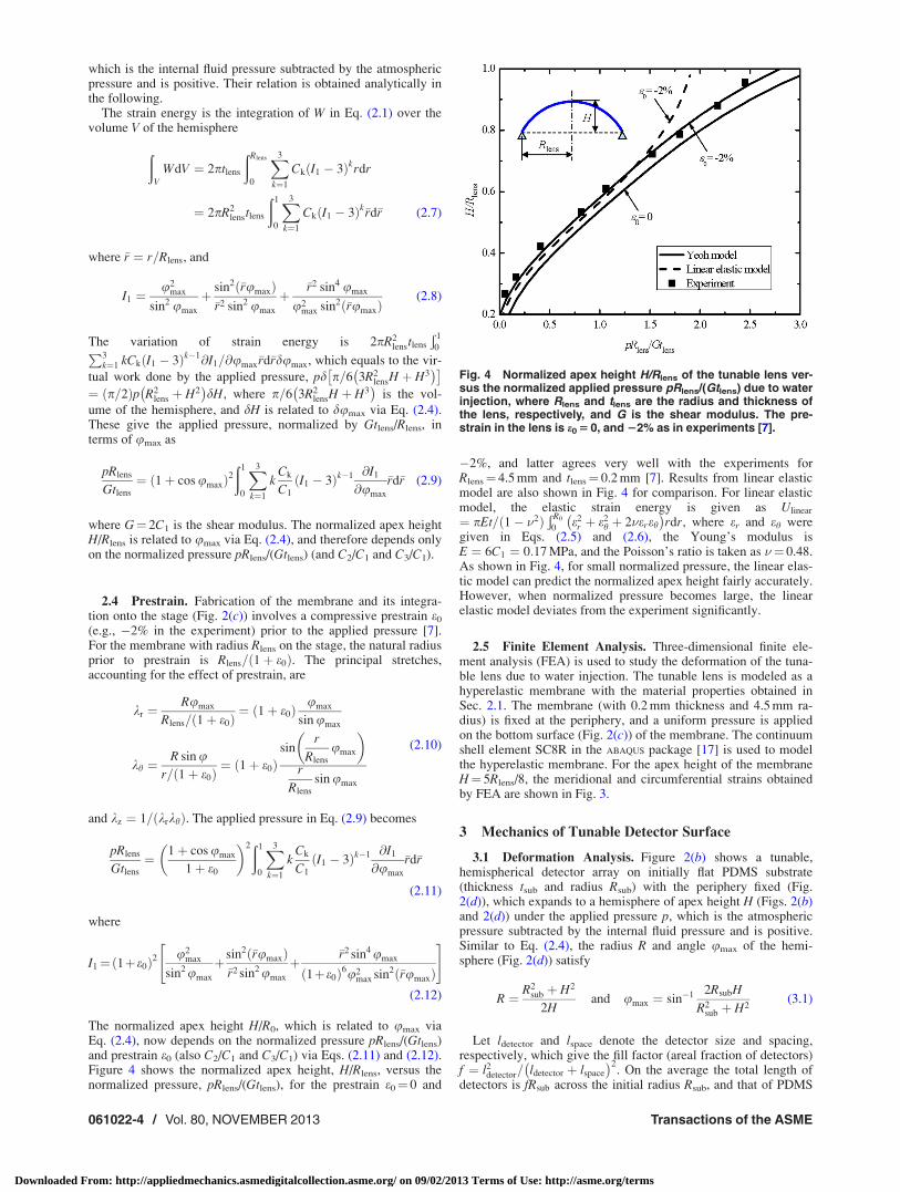
The normalized apex height H/R0, which is related to umax viaEq. (2.4), now depends on the normalized pressure pRlens/(Gtlens)and prestrain e0 (also C2/C1 and C3/C1) via Eqs. (2.11) and (2.12).Figure 4 shows the normalized apex height, H/Rlens, versus thenormalized pressure, pRlens/(Gtlens), for the prestrain e0¼ 0 and
�2%, and latter agrees very well with the experiments forRlens¼ 4.5 mm and tlens¼ 0.2 mm [7]. Results from linear elasticmodel are also shown in Fig. 4 for comparison. For linear elasticmodel, the elastic strain energy is given as Ulinear
¼ pEt=ð1� �2ÞÐ R0
0e2
r þ e2h þ 2�ereh
� �rdr, where er and eh were
given in Eqs. (2.5) and (2.6), the Young’s modulus isE ¼ 6C1 ¼ 0:17 MPa, and the Poisson’s ratio is taken as �¼ 0.48.As shown in Fig. 4, for small normalized pressure, the linear elas-tic model can predict the normalized apex height fairly accurately.However, when normalized pressure becomes large, the linearelastic model deviates from the experiment significantly.
2.5 Finite Element Analysis. Three-dimensional finite ele-ment analysis (FEA) is used to study the deformation of the tuna-ble lens due to water injection. The tunable lens is modeled as ahyperelastic membrane with the material properties obtained inSec. 2.1. The membrane (with 0.2 mm thickness and 4.5 mm ra-dius) is fixed at the periphery, and a uniform pressure is appliedon the bottom surface (Fig. 2(c)) of the membrane. The continuumshell element SC8R in the ABAQUS package [17] is used to modelthe hyperelastic membrane. For the apex height of the membraneH¼ 5Rlens/8, the meridional and circumferential strains obtainedby FEA are shown in Fig. 3.
3 Mechanics of Tunable Detector Surface
3.1 Deformation Analysis. Figure 2(b) shows a tunable,hemispherical detector array on initially flat PDMS substrate(thickness tsub and radius Rsub) with the periphery fixed (Fig.2(d)), which expands to a hemisphere of apex height H (Figs. 2(b)and 2(d)) under the applied pressure p, which is the atmosphericpressure subtracted by the internal fluid pressure and is positive.Similar to Eq. (2.4), the radius R and angle umax of the hemi-sphere (Fig. 2(d)) satisfy
R ¼ R2sub þ H2
2Hand umax ¼ sin�1 2RsubH
R2sub þ H2
(3.1)
Let ldetector and lspace denote the detector size and spacing,respectively, which give the fill factor (areal fraction of detectors)f ¼ l2
detector= ldetector þ lspace
� �2. On the average the total length of
detectors is fRsub across the initial radius Rsub, and that of PDMS
Fig. 4 Normalized apex height H/Rlens of the tunable lens ver-sus the normalized applied pressure pRlens/(Gtlens) due to waterinjection, where Rlens and tlens are the radius and thickness ofthe lens, respectively, and G is the shear modulus. The pre-strain in the lens is e0 5 0, and 22% as in experiments [7].
061022-4 / Vol. 80, NOVEMBER 2013 Transactions of the ASME
Downloaded From: http://appliedmechanics.asmedigitalcollection.asme.org/ on 09/02/2013 Terms of Use: http://asme.org/terms
(uncovered by detectors) is ð1� f ÞRsub. The stretch of PDMSunderneath the detectors is negligible since the tensile stiffness ofthe silicon photodetectors is several orders of magnitude largerthan that of PDMS (e.g., 0:16 MPa �m for silicon detector (thick-ness 1.2 lm and Young’s modulus 130 GPa) and 0:80kPa �m forPDMS (thickness 0.4 mm and Young’s modulus 2 MPa) as inexperiments [7]. Therefore, its length fRsub remains essentially thesame during the expansion due to applied pressure p, and thelength ð1� f ÞRsub of PDMS uncovered by the detectors expandsto Rumax � fRsub. This gives the principal stretches of PDMSuncovered by the detectors as
kr ¼Rumax � fRsub
1� fð ÞRsub
¼ 1
1� f
umax
sin umax
� f
� �
kh ¼R sin u� fr
1� fð Þr ¼ 1
1� f
sinr
Rsub
umax
� �r
Rsub
sin umax
� f
2664
3775
(3.2)
and kz ¼ 1= krkhð Þ.Fabrication of the detectors onto the stage (Fig. 2(d)) involves a
tensile prestrain e0 (e.g., 2% in the experiment) prior to the appliedpressure [7]. The principal stretches, accounting for the effect ofprestrain, are
kr ¼1þ e0
1� f
umax
sin umax
� f
1� f
kh ¼1þ e0
1� f
sinr
Rsub
umax
� �r
Rsub
sin umax
� f
1� f
(3.3)
and kz ¼ 1= krkhð Þ.
3.2 Pressure. The strain energy is the integration of strainenergy density in Eq. (2.1) over the volume of PDMS uncoveredby the detectors as 2p 1� fð ÞR2
sub= 1þ e0ð Þ2tsub
Ð 1
0P3k¼1 Ck I1 � 3ð Þk�rd�r, where
I1 ¼1þ e0
1� f
umax
sinumax
� f
1� f
� �2
þ 1þ e0
1� f
sin �rumaxð Þ�r sinumax
� f
1� f
2
þ 1þ e0
1� f
umax
sin umax
� f
1� f
� ��21þ e0
1� f
sin �rumaxð Þ�r sin umax
� f
1� f
�2
(3.4)
The principle of virtual work gives the applied pressure, normal-ized by Gtsub/Rsub, as
pRsub
Gtsub
¼ 1� fð Þ 1þ cos umax
1þ e0
� �2ð1
0
X3
k¼1
kCk
C1
I1 � 3ð Þk�1 @I1
@umax
�rd�r
(3.5)
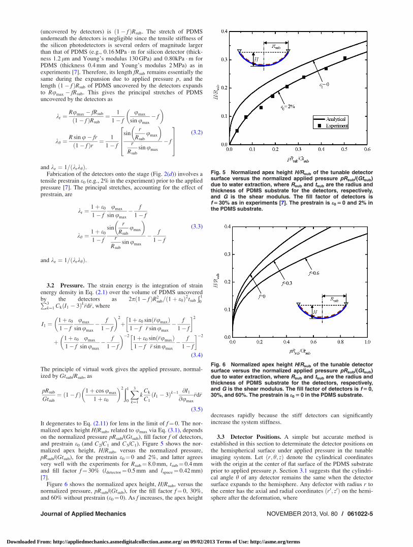
It degenerates to Eq. (2.11) for lens in the limit of f¼ 0. The nor-malized apex height H/Rsub, related to umax via Eq. (3.1), dependson the normalized pressure pRsub/(Gtsub), fill factor f of detectors,and prestrain e0 (and C2/C1 and C3/C1). Figure 5 shows the nor-malized apex height, H/Rsub, versus the normalized pressure,pRsub/(Gtsub), for the prestrain e0¼ 0 and 2%, and latter agreesvery well with the experiments for Rsub¼ 8.0 mm, tsub¼ 0.4 mmand fill factor f¼ 30% (ldetector¼ 0.5 mm and lspace¼ 0.42 mm)[7].
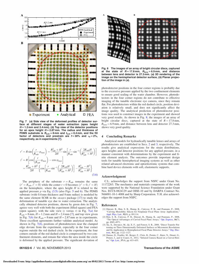
Figure 6 shows the normalized apex height, H/Rsub, versus thenormalized pressure, pRsub/(Gtsub), for the fill factor f¼ 0, 30%,and 60% without prestrain (e0¼ 0). As f increases, the apex height
decreases rapidly because the stiff detectors can significantlyincrease the system stiffness.
3.3 Detector Positions. A simple but accurate method isestablished in this section to determinate the detector positions onthe hemispherical surface under applied pressure in the tunableimaging system. Let r; h; zð Þ denote the cylindrical coordinateswith the origin at the center of flat surface of the PDMS substrateprior to applied pressure p. Section 3.1 suggests that the cylindri-cal angle h of any detector remains the same when the detectorsurface expands to the hemisphere. Any defector with radius r tothe center has the axial and radial coordinates r0; z0ð Þ on the hemi-sphere after the deformation, where
Fig. 5 Normalized apex height H/Rsub of the tunable detectorsurface versus the normalized applied pressure pRsub/(Gtsub)due to water extraction, where Rsub and tsub are the radius andthickness of PDMS substrate for the detectors, respectively,and G is the shear modulus. The fill factor of detectors isf 5 30% as in experiments [7]. The prestrain is e0 5 0 and 2% inthe PDMS substrate.
Fig. 6 Normalized apex height H/Rsub of the tunable detectorsurface versus the normalized applied pressure pRsub/(Gtsub)due to water extraction, where Rsub and tsub are the radius andthickness of PDMS substrate for the detectors, respectively,and G is the shear modulus. The fill factor of detectors is f 5 0,30%, and 60%. The prestrain is e0 5 0 in the PDMS substrate.
Journal of Applied Mechanics NOVEMBER 2013, Vol. 80 / 061022-5
Downloaded From: http://appliedmechanics.asmedigitalcollection.asme.org/ on 09/02/2013 Terms of Use: http://asme.org/terms
r0 ¼ R sinr
Rsub
umax
� �¼ R2
sub þ H2
2Hsin
r
Rsub
sin�1 2RsubH
R2sub þ H2
� �
z0 ¼ R cosr
Rsub
umax
� �� cos umax
¼ R2sub þ H2
2Hcos
r
Rsub
sin�1 2RsubH
R2sub þ H2
� � � R2
sub � H2
R2sub þ H2
� �(3.6)
The periphery of the substrate r ¼ Rsub remains the samer0 ¼ Rsub; z
0 ¼ 0ð Þ while the center r¼ 0 becomes r0 ¼ 0; z0 ¼ Hð Þon the hemisphere, where the apex height H is related to theapplied pressure p via Eq. (3.5) (also Figs. 5 and 6). The PDMSsubstrate (with 0.4 mm thickness and 8 mm radius) is modeled bythe same element SC8R in the ABAQUS package [17] to study thedeformation of tunable eye due to water extraction. The analyti-cally obtained detector positions, shown by green dots in Fig. 7,agrees very well with both the experiment (filled square) and FEA(open square); with the side view (z versus r) in Fig. 7(a) forRsub¼ 8 mm, H¼ 1.2 mm and H¼ 2.4 mm [7], and top view givenin Fig. 7(b) for Rsub¼ 8 mm and H¼ 2.87 mm as in experiments.These excellent agreements further validate analytical model. Asshown in Fig. 7(b), positions of photodetectors near the clampededge deviate from the experiment, especially in the four cornerregions outside the red dashed circle. In the experiment, the fourcorners outside of the red dashed circle is compressed by two con-finement elements, and remain flat when the area inside the circleis deformed by the applied pressure. The significant deviation of
photodetector positions in the four corner regions is probably dueto the excessive pressure applied by the two confinement elementsto ensure good sealing of the water chamber. However, photode-tectors in the four corner regions do not contribute to effectiveimaging of the tunable electronic eye camera, since they remainflat. For photodetectors within the red dashed circle, position devi-ation is relatively small, and does not significantly affect theimage quality. The analytical prediction of photodetector posi-tions was used to construct images in the experiment and showedvery good results. As shown in Fig. 8, the images of an array ofbright circular discs, captured at the state of R¼ 17.8 mm,Rlens¼ 6.9 mm, and distance between lens and detector 27.3 mm,shows very good quality.
4 Concluding Remarks
Analytical models for hydraulically tunable lenses and arrays ofphotodetectors are established in Secs. 2 and 3, respectively. Theresults give analytical expressions for the strain distributions,apex heights and detector positions for any applied pressure, in amanner consistent with determinations by the experiment and fi-nite element analysis. The outcomes provide important designtools for tunable hemispherical imaging systems as well as otherrelated advanced electronic and optoelectronic systems that com-bine hard device elements with soft, elastomeric supports.
Acknowledgment
C.L. acknowledges the support from NSFC under Grant No.11172263. The mechanics and materials components of the workwere supported by the National Science Foundation under GrantNos. ECCS-0824129 and OISE-10 and by DARPA Contract No.N66001-10-1-4008 and by Sharp Corporation. Y.H. also acknowl-edges the support from NSFC.
References[1] Dinyari, R., Rim, S. B., Huang, K., Catrysse, P. B., and Peumans, P., 2008,
“Curving Monolithic Silicon for Nonplanar Focal Plane Array Applications,”Appl. Phys. Lett., 92(9), p. 091114.
[2] Rim, S. B., Catrysse, P. B., Dinyari, R., Huang, K., and Peumans, P., 2008,“The Optical Advantages of Curved Focal Plane Arrays,” Opt. Express, 16(7),pp. 4965–4971.
[3] Xu, X., Davanco, M., Qi, X. F., and Forrest, S. R., 2008, “Direct Transfer Pat-terning on Three Dimensionally Deformed Surfaces at Micrometer Resolutionsand Its Application to Hemispherical Focal Plane Detector Arrays,” Org. Elec-tron., 9(6), pp. 1122–1127.
[4] Dumas, D., Fendler, M., Berger, F., Cloix, B., Pornin, C., Baier, N., Druart, G.,Primot, J., and le Coarer, E., 2012, “Infrared Camera Based on a Curved Reti-na,” Opt. Lett., 37(4), pp. 653–655.
Fig. 7 (a) Side view of the deformed profiles of detector sur-face at different stages of water extraction (apex heightH 5 1.2 mm and 2.4 mm). (b) Top view of the detector positionsfor an apex height H 5 2.87 mm. The radius and thickness ofPDMS substrate is Rsub 5 8 mm and tsub 5 0.4 mm, and the fillfactor of detectors and prestrain are f 5 30% and e0 5 2%,respectively, as in experiments [7].
Fig. 8 The images of an array of bright circular discs, capturedat the state of R 5 17.8 mm, Rlens 5 6.9 mm, and distancebetween lens and detector is 27.3 mm. (a) 3D rendering of theimage on the hemispherical detector surface, (b) Planar projec-tion of the image in (a).
061022-6 / Vol. 80, NOVEMBER 2013 Transactions of the ASME
Downloaded From: http://appliedmechanics.asmedigitalcollection.asme.org/ on 09/02/2013 Terms of Use: http://asme.org/terms

[5] Cossairt, O. S., Miau, D., and Nayar, S. K., 2011, “Scaling Law for ComputationalImaging Using Spherical Optics,” J. Opt. Soc. Am. A, 28(12), pp. 2540–2553.
[6] Ko, H. C., Stoykovich, M. P., Song, J. Z., Malyarchuk, V., Choi, W. M., Yu, C.J., Geddes, J. B., Xiao, J. L., Wang, S. D., Huang, Y. G., and Rogers, J. A.,2008, “A Hemispherical Electronic Eye Camera Based on Compressible SiliconOptoelectronics,” Nature, 454(7205), pp. 748–753.
[7] Jung, I. W., Xiao, J. L., Malyarchuk, V., Lu, C. F., Li, M., Liu, Z. J., Yoon, J.,Huang, Y. G., and Rogers, J. A., 2011, “Dynamically Tunable HemisphericalElectronic Eye Camera System With Adjustable Zoom Capability,” Proc. Natl.Acad. Sci. U. S. A., 108(5), pp. 1788–1793.
[8] Schneider, F., Mueller, C., and Wallrabe, U., 2008, “A Low Cost Adaptive Sili-cone Membrane Lens,” J. Opt. A, Pure Appl. Opt., 10(4), p. 044002.
[9] Sanchez-Perez, J. R., Boztug, C., Chen, F., Sudradjat, F. F., Paskiewicz, D. M.,Jacobson, R. B., Lagally, M. G., and Paiella, R., 2011, “Direct-Bandgap Light-Emitting Germanium in Tensilely Strained Nanomembranes,” Proc. Natl. Acad.Sci. U. S. A., 108(47), pp. 18893–18898.
[10] Ko, H. C., Shin, G., Wang, S. D., Stoykovich, M. P., Lee, J. W., Kim, D. H.,Ha, J. S., Huang, Y. G., Hwang, K. C., and Rogers, J. A., 2009, “CurvilinearElectronics Formed Using Silicon Membrane Circuits and Elastomeric TransferElements,” Small, 5(23), pp. 2703–2709.
[11] Shin, G., Jung, I., Malyarchuk, V., Song, J. Z., Wang, S. D., Ko, H. C., Huang,Y. G., Ha, J. S., and Rogers, J. A., 2010, “Micromechanics and AdvancedDesigns for Curved Photodetector Arrays in Hemispherical Electronic-EyeCameras,” Small, 6(7), pp. 851–856.
[12] Wang, S. D., Xiao, J. L., Jung, I., Song, J. Z., Ko, H. C., Stoykovich, M. P.,Huang, Y. G., Hwang, K. C., and Rogers, J. A., 2009, “Mechanics of Hemi-spherical Electronics,” Appl. Phys. Lett., 95(18), p. 181912.
[13] Wang, S., Xiao, J., Song, J., Ko, H. C., Hwang, K.-C., Huang, Y., and Rogers,J. A., 2010, “Mechanics of Curvilinear Electronics,” Soft Matter, 6(22), pp.5757–5763.
[14] Yeoh, O. H., 1993, “Some Forms of the Strain-Energy Function for Rubber,”Rubber Chem. Technol., 66(5), pp. 754–771.
[15] Rivlin, R. S., 1948, “Large Elastic Deformations of Isotropic Materials. 4. Fur-ther Developments of the General Theory,” Philos. Trans. R. Soc. London, Ser.A, 241(835), pp. 379–397.
[16] Schneider, F., Fellner, T., Wilde, J., and Wallrabe, U., 2008, “MechanicalProperties of Silicones for MEMS,” J. Micromech. Microeng., 18(6),p. 065008.
[17] ABAQUS, 2009 Analysis User’s Manual, Vl. 6.9, Dassault Systemes, Pawtucket,RI.
Journal of Applied Mechanics NOVEMBER 2013, Vol. 80 / 061022-7
Downloaded From: http://appliedmechanics.asmedigitalcollection.asme.org/ on 09/02/2013 Terms of Use: http://asme.org/terms


![Hemispherical Resonator Gyro [Akimov; $MP-043-06]](https://img.pdfslide.net/doc/110x75/5527500b550346e1358b47b0/hemispherical-resonator-gyro-akimov-mp-043-06.jpg)