Embed Size (px)
Citation preview

Journal of Earth Sciences and Geotechnical Engineering, Vol. 9, No. 3, 2019, 199-228
ISSN: 1792-9040 (print version), 1792-9660 (online)
Scientific Press International Limited
Mechanisms Involved in Maturation of Clay Seals
in Boreholes for Storing Spent Reactor Fuel
Roland Pusch1, Jörn Kasbohm2, Thao Hoang-Minh3 and Lan Nguyen-Thanh4
Abstract
Smectite clay, especially montmorillonite, is proposed for isolating canisters
containing highly radioactive waste (HLW) like spent reactor fuel placed in deep
boreholes. It is used for minimizing groundwater flow around and along waste
packages (“Buffer Clay”) and for providing them with ductile embedment for
eliminating risk of canister damage caused by displacements in the host rock. The
clay has the form of heavily compacted blocks of granules that swell in conjunction
with water uptake until their full hydration potential has been utilized. The dense
clay blocks are fitted in perforated supercontainers that are submerged in smectite
mud. The long-term chemical stability of the clay is sufficient for providing the
required waste-isolating capacity, which is primarily supplied by the heavyness of
stagnant, very salt groundwater at depth.
Keywords: Smectite clay, montmorillonite, isolating canisters, highly radioactive
waste (HLW), supercontainers, dry density, settlement, creep settlement,
microstructure of smectite clay.
1 Luleå University of Technology, Sweden 2 Greifswald University, Germany 3 Greifswald University, Germany 4 Technical University of Darmstadt, Germany.
Article Info: Received: June 5, 2019. Revised: August 23, 2019.
Published online: September 10, 2019.

200 Roland Pusch et al.
1. Introduction
We will consider here the evolution of ”Buffer” clay components in repositories for
spent nuclear fuel consisting of deep holes with 0-6-0.8 m diameter bored in
crystalline rock (Figure 1). The paper describes major physico-chemical
mechanisms involved in the maturation of clay seals, i.e. expansion/consolidation,
shear strain, and migration of water and radionuclides. Table 1 exemplifies clay
materials that are commercially available and provide effective isolation of HLW.
It summarizes typical properties of three types of smectitic clay referred to
throughout the paper. The values stem from tests of such clay materials saturated
with low- to high-calcium chloride concentrations. The swelling pressure is a
practical measure of the expandability of the clay [1]. Special conditions prevail in
deeply located repositories represented here by a concept named VDH (Very Deep
Holes), which is one of several possible versions [2].
Figure 1: Deep hole concept “VDH”. In the upper parts highly compacted
clay seals the holes. In the lower, “deployment” zone (2-4 km), sets of
“supercontainers” with high-level radioactive waste is embedded in dense
clay, and separated by very dense clay blocks. The supercontainers of copper
or Navy Bronze, steel or titanium will be submerged in soft clay mud [3].

Mechanisms involved in maturation of clay seals in boreholes for storing spent reactor fuel 201
Table 1: Typical geotechnical properties of clay seal materials saturated with
distilled water and 3.5% calcium chloride solution, respectively. K is hydraulic
conductivity and ps swelling pressure (index d= distilled water and index s= salt
water).
Smectite clay Dry density
[kg/m3]
Hydraulic conductivity
Kd/Ks [m/s]
Swelling pressure
psd/ pss [kPa]
Montmorillonite 1,350 5E-12/4E-12 1,020
Saponite 1,020 4E-12 1,250
Mixed-layer
illite/montmorillonite 1,530 E-12 1,200
One notices that the three clay types have approximately the same hydraulic
conductivity and expandability but for quite different dry densities. For the case in
focus here, i.e. deep boreholes, the clay in the upper part of the holes will not be
exposed to higher temperature than 60-70oC, whereas in the lower, waste-bearing
part, it will be heated up to 150oC for up to a few hundred years. The differences in
temperature and salinity affect the properties of the clay as described in the paper.
2. Microstructural constitution
2.1 Basics
Figure 2 depicts schematically the crystal structure of the expandable part of the
dominant clay minerals of the three reference clays montmorillonite, saponite and
mixed-layer clay.
Figure 3 shows transmission electron micrographs of microstructural organisation
of the respective clay mineral type. Figure 3 shows electron micrographs of the
reference clays with similar dry densities. The three reference clay minerals,
montmorillonite, saponite and smectite/illite mixed-layer clay are characterized by
domains of stacked lamellae with water molecule hydrates in the interlamellar space.
Montmorillonite is the most expandable type and is the only expandable species that
can have up to 3 interlamellar hydrates at saturation with Na and Mg [4].

202 Roland Pusch et al.
Figure 2: Left and central: Two possible montmorillonite crystal structures
with Al in the octahedral sheet, the left one being valid also for saponite
except that Mg is in the octahedral sheet. Right: Illite/muscovite mixed layer
clay mineral (Friedland clay).
Figure 3: Electron micrographs of reference clays with a dry density of about
1300-1400 kg/m3. Upper left: Transmission micrograph of Montmorillonite
(Black=densest part of clay matrix, Red= medium-dense matrix,
Green=softest matrix, White=open void). Upper right: Scanning micrograph
of Saponite. Lower: Transmission micrograph of Illite/smectite mixed layer
clay (Friedland clay). Length of the bar is 1 m.

Mechanisms involved in maturation of clay seals in boreholes for storing spent reactor fuel 203
2.2 Correlation of microstructural and bulk physical
2.2.1 Ganeralized microstructural model of smectitic clay
We focus here on clay-isolated highly radioactive waste in the form of spent nuclear
fuel contained in metal canisters lined with dense clay, in turn contained in
cylindrical supercontainers placed in deep holes bored in crystalline rock. The clay
linings and blocks make up the ”buffer” that serves to isolate them from rock
movements and groundwater flow. The clay must fulfill strict criteria in respect to
hydraulic performance, gas and heat conductivity as well as to rheological
behaviour. It must also have robust performance characteristics and longevity,
which is fulfilled by very dense montmorillonite or saponite (Mg-smectite).
The requirement that the extremely low hydraulic conductivity of the smectite
buffer shall be maintained for periods of hundreds of thousands of years makes the
longevity particularly important [5]. There is also need to retard diffusive transport
of errant radionuclides such that they would be harmless when emerging on land
surface environment. The necessary retardation time period ranges between 10,000
and 1,000,000 years. In this context one has to recognize that the temperature of the
canisters with HLW can reach 150oC for a few centuries, which very significantly
speeds up both flow and diffusion of contaminated porewater.
2.2.2 Constitution and motion of porewater and electrolytes
Comprehensive investigations of the physical state and properties of porewater in
clay have been made by various scientists. Particular effort has been put in
interpreting the behaviour of water at and around the freezing point which has led
to models like the one shown in Figure 4. It ascribes reduced mobility of the water
closest to mineral surfaces (“Water A”) with 0.003- 0.004Pas-1 viscosity extending
to about 1-2nm distance from montmorillonite base-planes, and 0.0015Pas viscosity
for water within 2-4nm distance from base-planes. In Water B ice crystals and
lenses begin to form if the temperature drops sufficiently much. Energy conditions
successively bring ordinary free water (”Water C”) with <0.001 Pas-1 viscosity, to
become interchanged with ”Water B” [6].

204 Roland Pusch et al.
Figure 4: Differences in water structure adjacent to the mineral surfaces in
montmorillonite in salt and fresh water, respectively. Water A is most
strongly mineral-bound and has higher viscosity, Water B is least viscous and
controls formation of ice lenses at freezig, and Water C is free from mineral
influence (After Drost-Hansen).
2.2.3 Impact of clay microstructure on the motion of water and electrolytes
Colloid chemistry has helped to understand and quantify motion of electrolytes in
smectite clay like montmorillonite. Basic phenomena are for example the exclusion
of anions from the interlamellar space in such clays because of the negative charge
of the smectite crystal lattices (“Donnan exclusion”), and partial exclusion of any
ions from very narrow channels in the clay microstructure (cf. Figure 5).

Mechanisms involved in maturation of clay seals in boreholes for storing spent reactor fuel 205
Figure 5: Distribution of cation and anions in percolated voids in
montmorillonite clay. Consolidation under external effective pressure closes
the central space which will ultimately contain only cations (After
Neretnieks).
The cat- and anions are not uniformly distributed in the clay-water matrix as
indicated in Figures 5 and 6. Thus, the interlamellar porewater, which is free from
anions, cannot be distinguished from the free porewater C in Figure 4, and ordinary
chemical analysis only gives the average composition. Expulsion of porewater
under successively increased pressure shows a change in composition since low
pressures expel water contained in large voids while high pressures cause water
from small voids and channels and from the interlamellar space to be released [7].
The practical meaning of this is that the dry density of smectitic clay seals should
be as high as possible for minimizing diffusive migration of radionuclides in ionic
form.

206 Roland Pusch et al.
Figure 6: Relative monovalent anion concentration (%) in a representative
volume (REV) for equilibrating 0.1 M monovalent electrolyte in MX-80 clay
with a density at water saturation of 2130kg/m3. The picture shows that
anions (red and yellow) are confined in the center of the widest channels
(50m) and that cations (blue) are close to the mineral surfaces and totally
dominant in the channels (After Lehikoinen, cf. [7]).
Another implication of the diagram in Figure 5 is that the large majority of the
channels in dense hydrated buffer clay contains viscous porewater saturated with
cations and that any forced percolation will set up electric potentials that counteract
and retard water migration [8]. The compression of dual porosity soil has been
treated theoretically by Murad et al [9], who considered porous systems with dual
porosity, in principle consisting of a porous particle matrix composed of permeable
particle aggregates with micropores. Their approach is basically that of fundamental
soil mechanics, making use of Terzaghi’s (1942 and Biot’s (1955) theories of
primary and secondary consolidation [10,11]. The first is related to macroscopic
processes, primarily stress-generated size reduction of macropores that provide
most of the permeability, and the second depending on the effect of stress/strain on
microscale. Murad et al considered the primary consolidation to be related to
compression of the coarse-grained structure, the rate of which is controlled by
dissipation of the load-generated porewater pressure, and secondary consolidation
the rate of which is dictated by creep of the particle skeleton. This view is also held
by the present authors who consider the creep strain to be partly related to shear-
induced strain where significant microstructural distortion takes place as
exemplified by Figure 7, and creep by accumulation of atomic motions on the
microscale in all parts of the clay element.

Mechanisms involved in maturation of clay seals in boreholes for storing spent reactor fuel 207
Figure 7: Microstructural changes by compression. The largest voids and
channels are compressed first in conjunction with shear-induced breakdown
of the clay matrix [12].
2.2.4 Permeation of water and contaminants
It has long been realized that transport paths in clay have the form of channels for
migration of water, fluids, gas and ions and dissolved matter as generalized in
Figure 8.
Figure 8: Microstructural model of hydrated montmorillonite and saponite
clay with a bulk total density of 1,800-2,000 kg/m3 (Dry density 1,270-
1.590kg/m3). For the lower density the bar is 0.1mm and for the higher
density it is 0.0 mm [13,14].

208 Roland Pusch et al.
A step to directly correlate the microstructural constitution of smectite buffer clay
with lab investigations was recently made by Bouchelaghem and Pusch [15]. They
modelled the hydraulic transmission of coupled “2D” TEM electron images by
using the technique of “Homogenization of Periodic Media”, distinguishing
between three levels: the microscopic level of clay particles, the mesoscopic level
of clay aggregates, mineral grains and inter-aggregate porosity, and the macroscopic
level of the sample subjected to hydraulic conductivity tests in the laboratory.
Several cases were distinguished as soft and dense gels, open voids forming
connected flow paths, or remaining occluded. For all three cases considered, starting
from the local description of fluid flow, expressions of the effective hydraulic
conductivity tensor were derived. The microstructure was obtained by image
analysis of digitalized micrographs in order to obtain the contours of the different
phases. These contours where then imported into a finite element-based software in
order to solve the local problems. Numerical computations allowed the authors to
investigate the contribution to macroscopic flow by the soft and dense gels in
connected and non-connected configurations (cf. Figure 9).
Figure 9: Identified connected macropores (grey) making up microstructural
channels in smectite clay with 1,300 kg/m3 (total) density. Magnification: 10
mm=1 micrometer [15].
These investigators modelled the hydraulic conductivity of compacted water-
saturated smectite clay based on the real microstructure and the ”Homogenization
of Periodic Media” approach employed for deriving the permeability tensor. This
has fully acknowledged the heterogeneous and multiscale microstructure of clay, as
well as locally varying physical flow properties. In summary, the three levels of
description considered, i.e. the microscopic level of clay particles etc, provided the
basis of numerical calculation of the hydraulic conductivity. It agreed well with the
experimentally determined conductivity and verified that such clays used for
isolation of radioactive matter have several phases of soft and dense gels and open
Mechanisms involved in maturation of clay seals in boreholes for storing spent reactor fuel 209
voids forming connected flow paths or being occluded. For all three cases
considered, starting from the local description of fluid flow, the expression of the
effective hydraulic conductivity tensor was derived. The microstructure was derived
from image analyses of digitalized electron transmission micrographs in order to
obtain the contours of the different phases. The contours were then imported into a
finite element-based software in order to solve the local problems. Numerical
computations gave the contribution to macroscopic flow by the soft and dense gels
in the connected and unconnected configurations.
The study strongly supports the applicability of an earlier model for through-flow
of smectite-rich clay considered as a system of gelfilled channels of different size
(cf. Figure 10) that led to the 3Dchan code worked out by Neretnieks and Moreno
(2009) [16], and that has been successfully used for modelling flow through soft,
medium-dense and dense smectite clays [13].
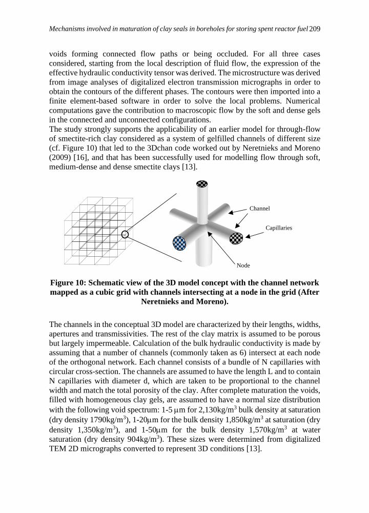
Figure 10: Schematic view of the 3D model concept with the channel network
mapped as a cubic grid with channels intersecting at a node in the grid (After
Neretnieks and Moreno).
The channels in the conceptual 3D model are characterized by their lengths, widths,
apertures and transmissivities. The rest of the clay matrix is assumed to be porous
but largely impermeable. Calculation of the bulk hydraulic conductivity is made by
assuming that a number of channels (commonly taken as 6) intersect at each node
of the orthogonal network. Each channel consists of a bundle of N capillaries with
circular cross-section. The channels are assumed to have the length L and to contain
N capillaries with diameter d, which are taken to be proportional to the channel
width and match the total porosity of the clay. After complete maturation the voids,
filled with homogeneous clay gels, are assumed to have a normal size distribution
with the following void spectrum: 1-5 m for 2,130kg/m3 bulk density at saturation
(dry density 1790kg/m3), 1-20m for the bulk density 1,850kg/m3 at saturation (dry
density 1,350kg/m3), and 1-50m for the bulk density 1,570kg/m3 at water
saturation (dry density 904kg/m3). These sizes were determined from digitalized
TEM 2D micrographs converted to represent 3D conditions [13].
Node
Channel
Capillaries

210 Roland Pusch et al.
2.3 Correlation of microstructural models and rheological behavior
2.3.1 Clay particle interaction
While most modellers make use of classical soil mechanical models that average
stress conditions and base their reasonings on elasto/plastic theory we prefer to
apply stochastic mechanics and do this by using what we call the Eyring/Feltham
model, named after the creators [16]. It can be described as follows, starting by
considering an element of soil or rock crystal matrix exposed to a shear stress that
causes strain along an arbitrarily selected plane through the cubical element with
“L” side-length (Figure 11). The passage of slip through the element displaces the
part above the slip plane by an amount “b” resulting in shearing by b/L.
The model is taken to represent rate process theory and has the form of a time- and
stress-dependent function controlled by the energy barrier spectrum on the
molecular level. The evolution of strain depends on the energy required to overcome
barrers representing the interparticle bond strength. This is a fundamental starting
point for evolution of stress/strain relationships that lead to practically useful
models for creep strain
Figure 11: Element undergoing internal displacement caused by a slip unit
jump generated by the local shear stress [16.
Following Pusch and Feltham [16,17] and assuming that interparticle slip has been
activated at a certain point, meaning that an energy barrier has been overcome, a
contribution to the overall shear strain has been made by the extension of the local
slip-patch. Summarizing the various contributions in the element, a linear
stress/creep-rate relation holds at very low stress levels, while at higher stresses the
strain rate increases rapidly. Experience shows that stable conditions prevail for
stresses lower than about 2/3 of the strength determined by using conventional
methods – uniaxial compression, direct shearing, triaxial testing - according to
which the strain rate tends to be successivly lower, while for high stresses the creep
tends to be proportional to time and ultimately leads to failure. For lower stresses
than 1/3 of conventionally tested materials the strain rate commonly reaches a final
definite value.

Mechanisms involved in maturation of clay seals in boreholes for storing spent reactor fuel 211
Equation 1 is an empirical expression that is generally referred to:
q apb= (1)
where:
a = q for p = 1 kPa
b = inclination of curve in logp/logq diagrams.
The experimental background is very limited but it is concluded from triaxial tests
that a-values range between 2.8 and 5.5 depending on the porewater chemistry and
type of adsorbed cation while b appears to have a constant value, 0.77.
Shearing takes place through the activation of barriers on the microstructural scale
to slip. The barriers are represented by bonds of various kinds, from weak Van der
Waals forces, via hydrogen bonds to strong primary valence bonds. They form a
spectrum of the type shown in Figure 12, exhibiting spatial differences in barrier
height.
Figure 12: Schematic energy barrier spectrum.
Particle aggregates and individual particles of rock-forming minerals behave as
strong units that remain intact for small strain but yield at large strain and contribute
to the bulk strength by generating dilatancy. The energy spectrum is hence not a
material constant but changes with strain and thereby with time. A fraction of the
strain-induced microstructural changes are preserved but exfoliated
montmorillonite stacks reorganize and cause self-healing by forming gels of
different density depending on the available space and rate of strain. This means
that local bond breakage is balanced by formation of numerous new bonds that make
the altering microstructural network stay coherent for low and moderate bulk shear
stresses, while higher shear stresses cause irreparable changes of the network
leading to bulk failure at a certain critical strain.
The response of the structure to a macroscopic shear stress is that the overall
deformation of the entire network of particles changes by disintegration, translation
0
2
4
6
8
10
0 5 10
Rela
tive
ab
un
da
nc
e
Energy barrier height
212 Roland Pusch et al.
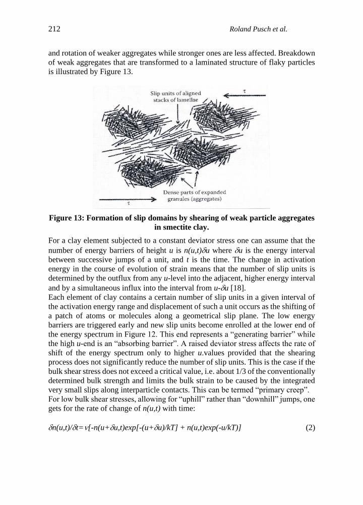
and rotation of weaker aggregates while stronger ones are less affected. Breakdown
of weak aggregates that are transformed to a laminated structure of flaky particles
is illustrated by Figure 13.
Figure 13: Formation of slip domains by shearing of weak particle aggregates
in smectite clay.
For a clay element subjected to a constant deviator stress one can assume that the
number of energy barriers of height u is n(u,t)u where u is the energy interval
between successive jumps of a unit, and t is the time. The change in activation
energy in the course of evolution of strain means that the number of slip units is
determined by the outflux from any u-level into the adjacent, higher energy interval
and by a simultaneous influx into the interval from u-u [18].
Each element of clay contains a certain number of slip units in a given interval of
the activation energy range and displacement of such a unit occurs as the shifting of
a patch of atoms or molecules along a geometrical slip plane. The low energy
barriers are triggered early and new slip units become enrolled at the lower end of
the energy spectrum in Figure 12. This end represents a “generating barrier” while
the high u-end is an “absorbing barrier”. A raised deviator stress affects the rate of
shift of the energy spectrum only to higher u.values provided that the shearing
process does not significantly reduce the number of slip units. This is the case if the
bulk shear stress does not exceed a critical value, i.e. about 1/3 of the conventionally
determined bulk strength and limits the bulk strain to be caused by the integrated
very small slips along interparticle contacts. This can be termed “primary creep”.
For low bulk shear stresses, allowing for “uphill” rather than “downhill” jumps, one
gets for the rate of change of n(u,t) with time:
n(u,t)/t=[-n(u+u,t)exp[-(u+u)/kT] + n(u,t)exp(-u/kT)] (2)

Mechanisms involved in maturation of clay seals in boreholes for storing spent reactor fuel 213
where:
u=width of an energy spectrum interval
=vibrational frequency (about E11 per second)
t=time
k=Boltzmann’s constant
T=absolute temperature
Using Equation (2) and introducing Feltham’s transition probability parameter to
describe the time-dependent energy shifts and that each transition of a slip unite
between consecutive barriers gives the same contribution to the bulk strain one gets
the bulk shear strain rate as in Equation (3) with t<to as boundary condition:
d/dt= (1-t/to) (3)
where is a stress-related material constant, and to depends on the deviator stress,
temperature and structural details of the slip process. The creep strain can be
expressed as Equation 4, which implies that it starts off linearly with time and then
dies out as exemplified by Figure 14.
=t –t2, (t<a/2) (4)
Figure 14: Creep strain of smectite-rich clay (MX-80) with a density at
saturation with distilled water of 1,500kg/m3. Double shear box apparatus,
average shear stress 6kPa.

214 Roland Pusch et al.
For higher bulk stresses the strain on the microstructural level yields some
irreversible changes associated with local breakdown and reorganization of
structural units, like in Figure 13. Still, there is repair by inflow of new low-energy
barriers parallel to the strain retardation caused by the successively increased
number of slip units being stopped by meeting higher energy barriers. This type of
creep can go on for ever without approaching failure. Following Feltham the process
of simultaneous generation of new barriers and migration within the transient
energy spectrum lead to the expression for the creep shear rate in Equation (5).
Feltham demonstrated that for thermodynamically appropriately defined limits of
the u-spectrum the strain rate appertaining to logarithmic creep takes this form
[17,18]:
d/dt=BT/(t+to) (5)
where B=is a function of the shear stress .
to is a constant of integration which leads to a creep relation closely representing the
commonly observed logarithmic type implying that the creep strain is proportional
to log(t+to).
The significance of to is understood by considering that in the course of applying a
deviatoric stress the deviator rises from zero to its nominal, final value (Figure 15).
A u-distribution exists at t=0, i.e., immediately after full load is reached, which may
be regarded as equivalent to one which would have evolved in the material initially
free from slips, had creep taken place for a time to before loading. Thus, to is
characteristic of the structure of the prestrained material including the impact of
cementing precipitations [18].
Figure 15: Generalization of creep curves of log time type showing the
meaning of to.
Time after onset of creep, log scale
Str
ain
, lo
g s
cale
to (-)
to (+)

Mechanisms involved in maturation of clay seals in boreholes for storing spent reactor fuel 215
There are two important implications of this model, firstly that the lower end of the
energy spectrum mainly relates to breakage of weak bonds and establishment of
new bonds where stress relaxation has taken place due to stress transfer from
overloaded parts of the microstructural networks to stronger and more rigid parts. It
also means that, for deviators below a critical level, the energy spectrum undergoes
a “blue-shift”, meaning that the content of high energy barriers increases, as
illustrated in Figure 16. The bulk shear strength hence increases with time, as does
the bulk stiffness, which implies, in turn, that the system remains stable for very
long periods of time exhibiting successive retardation of the creep, but that the clay
becomes brittle and can collapse quickly if the bulk shear load is raised to a critically
high level.
Figure 16: Example of activation energy spectrum for interparticle slip at
different times after the onset of creep [18].

216 Roland Pusch et al.
Figure 17: Evolution of creep for critically high shear stresses.
For intermediate bulk stresses actual creep tests of smectite-rich clay have given
results exemplified in Figure 18.
Further increase in deviator stress leads to what is conventionally termed
“secondary creep” in which the strain rate tends to be constant and causes strain that
is almost proportional to time. Following the same reasoning as for the lower stress
cases one can imagine that creep of critically high rate makes it impossible for
microstructural self-repair: comprehensive slip changes the structure without
allowing reorganization, which yields a critical strain rate which unevitably leads
to failure (Figure 17). For smectite clay shear-induced formation of slip units,
consisting of stacks of lamellae, is much more comprehensive than in illitic and
kaolinite-rich clays. The successive increase in the number of slip units in fact
implies an important self-sealing ability that causes attenuation of the creep rate of
smectite-rich clay even for high shear stresses as indicated by the diagram in Figure
18. Figure 19 represents creep testing of smectitic clay indicating that smectite-rich
clays under critically high shear stresses behave as Newton fluids and undergo
“secondary creep” ending with failure in agreement with Figure 17.

Mechanisms involved in maturation of clay seals in boreholes for storing spent reactor fuel 217
Figure 18: Creep strain of montmorillonite-rich clay (MX-80) for the average
shear stresses 39, 23 and 11kPa (from top). Density at saturation with
distilled water 1,940 kg/m3.
Figure 19: Creep of the same sample as in Figure 14 by increasing the shear
stress to 23kPa. The creep rate attenuated but turned into a constant,
relatively low strain rate without leading to failure in the two weeks long test
performed at room temperature.
1,00E-09
1,00E-08
1,00E-07
1,00E-06
1,00E-05
100 1000 10000 100000 100000
0
Time after loading, seconds
Sh
ea
r s
tra
in, p
er
se
co
nd
1.00E-10
1.00E-09
1.00E-08
1.00E-07
1.00E-06
1.00E-05
1.00E-04
1.00E-03
1.00E-02
1.00E-01
1.00E+00
1 10 100
Str
ain
rate
, str
ain
pe
r seco
nd
Time after onset of creep, days

218 Roland Pusch et al.
In summary, the following features of the creep model are assumed:
• Each element of clay contains a certain number of slip units in a given
interval of the activation energy range and displacement of such a unit is
taken to occur as the shifting of a patch of atoms or molecules along a
geometrical slip plane (Figure 10). In the course of the creep the low energy
barriers are triggered early and new slip units come into action at the lower
energy end of the spectrum in Figure 16. This end represents a “generating
barrier” while the high u-end is an “absorbing” barrier,
• A changed deviator stress affects the rate of shift of the energy spectrum
only to higher u-values provided that the shearing process does not
significantly reduce the number of slip units. This is the case if the bulk
shear stress does not exceed a certain critical value, which is on the order of
1/3 to 2/3 of the conventionally determined bulk strength. The creep rate is
initially linear with time, then drops and finally dies out. It implies that the
microstructural constitution remains unchanged and that bulk strain
corresponds to the integrated very small slips along interparticle contacts. In
principle this can be termed “primary creep”
• For intermediate bulk shear stresses, allowing for “uphill” rather than
“downhill” jumps on the energy spectrum, creep retards according to a log
time function and reaches a finite specific value for a given period of time.
2.3.2 A typical creep case – the settlement of a 20 ton canister with spent fuel
resting in dense ”buffer” clay
The creep case considered here is illustrated by Figure 20, which shows a cross
section of a repository at 400 m depth representing the concept of Swedish Nuclear
Fuel and Waste Management Co (SKB). The integration of the soft clay mud in
which the heavy supercontainer with canister and dense clay were submerged is
assumed to have taken place, implying that the buffer clay (”bentonite”) has
expanded and consolidated the mud. This process has been investigated in detail by
Yang [19].

Mechanisms involved in maturation of clay seals in boreholes for storing spent reactor fuel 219
Figure 20: SKB’s concept KBS-3V. The canister with spent fuel has a weight
of about 25 tons [20].
The time-dependent settlement of the supercontainer was calculated by using
Equation 6 and the boundary element (BEM) code BEASY worked out by
Computational Mechanics Center (CMI, Southampton, England), which also made
the calculations.
The diameter and height of the canister was 1.05m and 4.8m, respectively. It was
assumed to rest on 0.5 m clay, be surrounded by 0.35m clay and covered by 1.5m
clay, all confined in a bored hole with 7m depth in rigid rock. The E-modulus of the
clay was taken as 300MPa and Poisson’s ratio taken as 0.49. Room temperature was
assumed.
The settlement rate was predicted by use of Equation 6, which is a generalized
version of Equation 5 [21]:
ds/dt = T D ln t (6)
=3E-10 K-1, kPa-1 = creep strain parameter evaluated from undrained triaxial tests
of montmorillonite-rich clay with the dry density 1,590kg/m3 at room temperature.
D = 1 – 2 (average deviator stress), 1>2=3 principal stresses.

220 Roland Pusch et al.
Table 2: Predicted settlement of full-scale canister at 20oC for =3E-10 [K-1kPa-1]
with and without slip along the contact between clay and rock and canister.
Time after onset
of creep [sec]
Predicted settlement with
slip along the contact
between clay and rock
[mm]
Recorded settlement
without slip [mm]
E0 0.358 0.049
E1 0.426 0.058
E2 0.493 0.068
E3 0.560 0.077
E4 0.627 0.086
E5 0.695 0.095
E6 0.762 0.105
The calculated settlement assuming no friction/adhesion along the contact between
clay and rock, will theoretically be between one third and half of a millimeter in 10-
100 years. The rate of settlement then drops quickly and becomes ¾ of a millimeter
after E6 seconds. In practice, the rate of settlement will be either slower because of
the stiffening effect of precipitated silicious compounds, or faster because of
compression as discussed later in the paper. Before examining the effect of such
processes, we will describe a laboratory experiment of the same type.
2.3.3 Laboratory-scale experiment
The just described case of canister settlement was investigated by conducting a
small-scale test that involved recording of the movement of a model canister
embedded in the same type of dense montmorillonite-rich clay at constant
temperature of 21.5-22.0oC (Figure 21). The clay was precompacted and trimmed
to fit in the load cell with access to distilled water via a filter for 3 months, giving
complete saturation at a density of 2,000kg/m3 (dry density 1,590kg/m3).

Mechanisms involved in maturation of clay seals in boreholes for storing spent reactor fuel 221
Figure 21: Experiment for determining the settlement of a model canister
embedded in clay under drained conditions and carrying a dead-load of 800
N [21].
The 50mm diameter canister was loaded by 800N after 3 months of maturation of
the clay with access to water from the filter-equipped container for homogenization.
The contact pressure between the canister base and the clay, neglecting wall friction,
was thence 400kPa. The settlement was recorded with an accuracy of E-4m. The
load application caused settlement of visco-elastic type amounting to 2-3m in the
first few hours. The total creep strain was about 6m after 2 months loading and
about 7m after 3 months. It was approximately proportional to log time with a
slightly dropping trend, approximately in agreement with Eq.5. The same type of
settlement calculation as for the full-scale case with 20t canister in montmorillonite-
rich clay with the same dry density, i.e. 1,590kg/m3 was made giving results that
agreed well with the recorded ones as illustrated by Table 3. The predicted
distribution of the vertical movements in the clay after E6 seconds is illustrated in
Figure 22, showing that there would be upward movements in the clay up to about
25mm above the base of the canister, and that downward and lateral movements
dominated below it.
50 mm
145 mm
300 mm
800 Pa
Strain gauge
Load cell
”Canister”
Filter for
uniform
wetting
of the
clay
Clay
0
1
2
3
4
5
6
7
8
1,00E+05 1,00E+06 1,00E+07 1,00E+08
Time after loading, s
Sett
lem
en
t,
m

222 Roland Pusch et al.
Figure 22: Calculated distribution of the vertical displacements in the clay
6E6 seconds after loading assuming slip along the clay/cell and clay canister
contacts (minus represents upward movement, plus is upwards), [21].
Table 3: Predicted and actual settlement of the model canister at 20oC
for =3E-10 [K-1 kPa-1]
Time after loading [sec] Predicted settlement [m] Recorded settlement [m]
3E5 (0.01 y) 3.0 3.0
6E5 (0.02 y) 4.0 3.7
3E6 (0.10 y) 5.0 5.2
6E6 (0.20 y) 6.0 6.0
2.4 Creep behaviour of clay seals loaded by waste canisters in boreholes
Log-time creep behaviour of dense montmorillonite-rich clay for medium-high
shear stresses has been frequently recorded in laboratory and bench-scaled
investigations like the study by Al-Thaie et al, 2014 [22]. Their study also showed
that even relatively low amounts of this mineral largely control the rheological
behaviour of clays (Figure 23). According to the diagram in this figure the clay with
25% montmorillonite content gave slightly quicker retardation of the creep rate than
the clay with 50% content of montmorillonite for any stress level, which can be
ascribed to the higher content of strong barriers (non-clay minerals) of the first
mentioned.
Secondary consolidation by long-term loading under drained conditions has the
same character: the settlement of the canister approximately obeys the expression:

Mechanisms involved in maturation of clay seals in boreholes for storing spent reactor fuel 223
s=CHln(t2-t1) (7)
where C=material coefficient, H=thickness of loaded clay layer, t1=time for start of
settlement and t2=time for ending the period considered [10].
Figure 23: Strain rates for different shear stresses on equally dense clays with
25 and 50% montmorillonite content (GC). The percentages refer to the
fraction of the conventionally determined shear strength of the respective
clay [22]. All curves indicate, in principle, log time strain behaviour.
2.5 Physico/Chemical stability of montmorillonitic clays and its impact on
creep behaviour
The physical and chemical stabilities of montmorillonite are classic matters in deep-
boring technologies and are briefly commented in this paper.
2.5.1 Physical stability
A major problem to be considered is the risk of dessication of the clay surrounding
canisters in a KBS-3 repository located in very dry crystalline rock. Experience
from full-scale field tests indicates that water saturation of the clay can require a
hundred years or more and lead to fissuring that can be permanent when silica is
precipitated according to the generally accepted mineral conversion process
[1,22,23]:
Montmorillonite > Illite + Quartz + Chlorite (8)
The conversion to illite means that voids in montmorillonite increase in size and
interconnectivity by which the average hydraulic conductivity increases by at least
one order of magnitude and the swelling pressure is reduced by one- to two orders
of magnitude depending on the type of adsorbed cation and degree of silicification.

224 Roland Pusch et al.
For the deep-hole concept VDH, with dense montmorillonite clay forming multiple
seals in the holes, water saturation and maturation is quick because of the high water
(mud) pressure [14,24].
2.5.2 Chemical stability
Clay seals
Equation 7 has been used by a number of investigators for predicting the
degradation rate of montmorillonite clay exposed to temperatures of up to several
hundred centigrades for a million years using theoretical models based on the classic
Arrhenius’ equation [23,24,25,26]. The results indicate that for 100oC temperature,
which is a recommended maximum by most regulators, the original
montmorillonite content is expected to drop from 100% to 50% in E4 years and to
10% in E5 years. For 150oC during 1,000 years, which is the expected heat pulse
for the lowest part of a VDH repository, the intact part of the montmorillonite would
be 50%. As mentioned, silica cementation at this temperature would strongly reduce
the expandability and self-sealing ability already after some decades. The
expandability indicated in Figure 24 would be lost.
Figure 24: Montmorillonite depicted in CNRS’ high-voltage transmission
microscope. Upper: air-dry condition. Lower: the same specimen wetted and
expanded by water saturation [27].
Concrete in deep holes
Concrete will be used for stabilization of deep deposition holes as indicated in
Figure 1. Ordinary concrete with Portland cement as binder would be short-lived
and degrade contacting clay seals, while use of low-pH cement and inorganic
superplastizicers (talc) that do not give off organic colloids that can transport
radionuclides, will do. The cement/clay reaction products contribute to the strength
of the concrete [14,27].

Mechanisms involved in maturation of clay seals in boreholes for storing spent reactor fuel 225
3. Comments and conclusions
The following major conclusions from the study can be summarized as follows:
• The microstructure of smectite clay used for sealing off waste packages
containing highly radioactive waste like spent fuel in repositories of mined
type or consisting of deep boreholes controls the transport of water and ions
as well as the rheological performance [28],
• Considerable microstructural changes are caused by the hydrothermal
conditions, which are similar for the depth of mined repositories - 400-500
m - and for the upper parts of very deep holes - 1,000-2,000 m, but much
more comprehensive at 2,000-4,000 m depth to which deep boreholes for
disposal of such waste extend,
• Stress/strain performance of clays is significantly affected by contents of
smectitic clays, especially of montmorillonite, even at contents as low as 25
%. The reason is the strong hydrophilic potential and role of porewater held
in both intra- and extra-lamellar positions of such clays, which has an
extreme particle surface area
• The intra- and interparticle bonds represent energy spectra ranging from
very low levels to that of primary valence bonds, which explains the
importance of shear stress: creep at constant water content is dominated by
relative displacement of neighbouring particles that can be large without
causing breakage of the particle netwoek by successive self-repair via shifts
of the interparticle bond energy spectrum (”blue-shift”) as long as the bulk
shear stress is moderate (Figure 25)
Figure 25: Microstructural constitution of montmorillonite-rich clay (MX-80)
sample saturated with 10% CaCl2 solution and hydrothermally treated at
95oC, placed in a shear box for shearing along the joint between the two box
parts (brown line). Magnification 200x. On-falling LED light.

226 Roland Pusch et al.
• The chemical stability of clay seals from 2,000-4,000 m depth in bored holes
is lower than in shallow, mined, repositories because of the higher
temperature, up to 150oC for a few centuaries after placing HLW waste
packages. The hydrothermal impact on clay microstructure causes
aggregation, increased hydraulic conductivity and loss of ductility because
of cementation by precipitation of silicious matter (Figure 26). The net
isolating capacity of clay seals is, however, lower in shallow, mined
repositories than in deep boreholes where there are no horizontal hydraulic
gradients and where the groundwater has high density because of the high
salt content making it stay at depth.
Figure 26: The clay sample in Figure 25 sheared after hydrothermal
treatment at 95oC. The white object to the right is one of the shear box halves.
The fracturing that took place in conjunction with dilatancy at about 20 %
strain in the sheared direction (right to left) demonstrates brittle behaviour
and lack of self-sealing ability of the clay. Magnification 200x. On-falling
LED light.

Mechanisms involved in maturation of clay seals in boreholes for storing spent reactor fuel 227
References
[1] Herbert, H. J., Kasbohm, J., Sprenger, H., Fernández, A.M. and Reichelt, C.
(2008). Swelling pressures of MX-80 bentonite in solutions of different ionic
strength. Physics and Chemistry of the Earth, vol. 33, 2008, (327-342).
[2] Brady, P.V, Arnold, B.W., Freeze, G.A., Swift, P.N., Bauer, S.J., Kanney, J.L,
Rechard, R.P. and Stein, J.S (2009). Deep borehole disposal of high-level
radioactive waste, SANDIA REPORT 2009-4401, New Mexico/Livermore
Calif. USA, 2009.
[3] Pusch, R., Yong., R.N. and Nakano, M. (2018). Geologic Disposal of High-
Level Radioactive Waste. CRC Press, Taylor and Francis Group.
[4] Kehres, A. (1983). Isotherms de deshydratation des argiles. Energies
d’hydratation Diagrammes de pores surfaces internes et externes. PhD thesis
Université Paul Sabatier, Toulouse, France.
[5] Yong, R.N., Nakano M. and Pusch, R. (2012). Environmental Soil Properties
and Behaviour, CRC Press, ISBN 9781439845295.
[6] Ichikawa, Y., Kavamura, K., Nakano, M., Kitayama, K. and Kawamura, H.
(1998). Unified molecular dynamics/homogenization analysis. In: Proc. on
International High-level Radioactive Waste Management Conference, Las
Vegas, US.
[7] Pusch, R., Muurinen, A., Lehikoinen, J., Bors, J. and Eriksen, T. (1999).
Microstructural and chemical parameters of bentonite as determinants of waste
isolation efficiency. Final Report of EC Projact Contract F14W-CT95-0012,
European Commision, Brussels.
[8] Pusch, R. (2008). Geological Storage of Radioactive Waste. Springer Verlag,
Berlin-Heidelberg.
[9] Murad, M.A., Guerreiro, J.N. and Loula, A.F.D. (2008). Micromechanical
computational modelling of secondary consolidation and hereditary creep in
soils. Computer Methods in Applied Mechancs and Engineering, Elsevier Publ.
Co.
[10] Terzaghi, K. (1942). Theoretical Soil Mechanics. Wiley, US.
[11] Biot, M. (1955). Theory of elasticity and consolidation for a porous anisotropic
soil. J. Appl. Physics, 26, 1955 (182-185).
[12] Pusch, R. (1970). Clay Microstructure. Swedish National Council for Building
Research, Document D:8, Stockholm, Sweden.
[13] Pusch, R. and Yong, R.N. (2006). Microstructure of Smectite Clays and
Engineering Performance. Taylor and Francis, NY, USA. ISBN10: 0-415-
36863-4.
[14] Pusch, R. (2015). Bentonite Clay. Environmental Properties and Applications.
CRC Press, Taylor and Francis Group.
[15] Bouchelaghem, F. and Pusch, R. (2017). Fluid flow and effective conductivity
calculations on numerical images of bentonite microstructure. Applied Clay
Science, 144, (9-18).

228 Roland Pusch et al.
[16] Pusch, R. (1979). Creep of soils. Ruhr-Universität Bochum, Schriftenreihe des
Instituts fuer Grundbau, Wasserwesen und Verkehrswesen, Serie Grundbau
Heft 5.
[17] Feltham, P. (1968). A stochastic model of creep. Phys. Stat. Solidi, 30, (135-
146).
[18] Pusch, R. and Feltham, P. (1980). A stochastic model of creep of soils.
Geotechnique, 30/4, (397-506).
[19] Yang, T. (2017). Maturation of Clay Seals in Deep Boreholes for Disposal of
Radioactive Waste, Ph. Thesis, Luleå Technical University, Luleå, Sweden.
[20] Svemar, C. (2005). Cluster Repository Project (CROP). Final reåprt of
European Commission Contract FIR-CT-2000.20023, Brussels, Belgium.
[21] Pusch, R. and Adey, R. (1999). Creep in buffer clay. SKB Technical Report
TR-99-32. SKB, Stockholm, Sweden.
[22] Al-Thaie, L., Pusch, R. and Knutsson, S. (2014). Hydraulic properties of
smectite rich clay controlled by hydraulic gradients and filter types. Applied
Clay Science 87, (73-80). http://dx.doi.org/10.1016/j.clay.2013.11.027.
[23] Pytte, A.M. and Reynolds, R.C. (1989). The thermal transformation of
smectite to illite. In: Thermal History of Sedimentary Basins. N.D. Naeser &
T.H. McCulloh, eds. Springer Verlag (133-140).
[24] Grindrod, P, and Takase, H. (1993). Reactive chemical transport within
engineered barriers. In: Proc. 4th Int. Conf. on the Chemistry and Migration
Behaviour of Actinides and Fission Products in the Geosphere, Charleston, SC
USA, 12-17 Dec. Oldenburg Verlag 1994 (773-779).
[25] Gueven, N. and Huang, W.L. (1990). Effects of Mg2+ and Fe3+ substitutions
on the crystallization of discrete illite and illite/smectite mixed layers. Dept.
Geosciences Texas Tech University, Exxon Production research Co, Houston,
Texas, USA.
[26] Kasbohm, J., Pusch, R., Nguyen, T.L. and Hoang, M.T. (2013). Lab scale
performance of selected expandable clays under HLW repository near-field
view. Environmental Earth Sciences, 69, (2569-2579).
[27] Mohammed, M. H., Pusch, R., Al-Ansari, N., Knutsson, S., Emborg, M.,
Nilsson, M., and Pourbakhtiar, A. (2014). Talc-Based Concrete for Sealing
Borehole Optimized by Using Particle Packing Theory. J. of Civil Engineering
and Architecture, Apr. 2013, 7, 4, (440-455).
[28] Warr, L.N., and Grathoff, G.H. (2010). Sealing of investigation boreholes:
Mineralogical and geochemical borehole plug analyses. Technical Report,
Swedish Nuclear Fuel and Waste Management Co., Ernst-Moritz-Arndt-
Universität, Greifswald, Germany.