Embed Size (px)
Citation preview
PA
GE
1MEDIUM DUTY C & T SERIES
MDC&T Rev. 12/98
BODY BUILDER INFORMATION
The Incomplete Vehicle Document (IVD) is supplied with each incomplete vehicle,and provides information that should be used by intermediate and final stagemanufacturers in determining conformity to applicable Federal Motor Vehicle SafetyStandards (FMVSS). The IVD also includes information which must be followed inorder to ensure that Environmental Protection Agency (EPA) and California emissionscertification requirements and NHTSA Fuel Regulations are met.
This Body Builders Book contains information that may be used in addition to the IVDfor any manufacturer making alterations to an complete/incomplete vehicle. No alter-ation should be made to the incomplete vehicle which either directly or indirectly re-sults in any component, assembly or system being in nonconformance with any appli-cable Federal Motor Vehicle Safety Standard or Emission Regulation. Intermediateand final stage manufacturers should be familiar with all Federal Motor Vehicle SafetyStandards and Emission Regulations and aware of their specific responsibilities asmanufacturers.
For further assistance contact Upfitter Integration at: 1 (800) 875–4742
Section 0 – General Instructions
Check for proper clearance between body members and chassis components whichmay in any way affect the reliability and performance of the vehicle by developingabrasion and wear points from moving parts or degradation from extreme environ-ment or thermal exposure or may increase interior noise.
Check headlamp aim and all vehicle illumination systems for proper operation whenthe vehicle has been completed. Re-aim headlamps when necessary. Check forproper operation of windshield washer, wipers and defroster system.
Extreme care must be taken when working on vehicles equipped with Brake ControlModule (BCM), Engine Control Module (ECM), Powertrain Control Module (PCM),Transmission Control Module (TCM), Vehicle Control Module (VCM). (See Owner’sManual).
If arc-welding is employed on the chassis, precautions must be taken to protect allvehicle components, especially brake, fuel lines and fuel tank assembly, electrical wir-ing and BCM/ECM/PCM/TCM or VCM. To avoid electronic component damage, dis-connect battery (batteries); disconnect the negative cable first, followed by the posi-tive. To reconnect cables; connect the positive first, then the negative.
All labels on the vehicle (any message applied to the vehicle or vehicle componentthat informs, instructs, or warns) must appear on the completed vehicle so the usercan read them easily and without obstruction.
Service and service replacement parts for your add-on systems may not be availablefrom a GM dealer. Those installing aftermarket systems should provide informationas to where and how to obtain service.
When installing a Power Take-Off (PTO) with hydraulic lines, the following care shouldbe exercised:
� Route and secure all hydraulic lines so that they are not in close proximity toany parts of the exhaust system. Keep all fittings and connections away fromthe exhaust system. Make sure connections and fittings cannot leak on theexhaust system.
� Exhaust system heat can damage and degrade hydraulic lines andcomponents. Oils and hydraulic fluid coming in contact with a hot exhaustsystem could result in a fire.
Section 1 – Body
Body structures, interior and accessory arrangements must be designed into the ve-hicle to provide for proper load distribution on both axles and not to exceed any grossaxle weight ratings. Lateral load equalization must also be maintained. The resultantCenter of Gravity of the unladen vehicle must be within the limits tabulated in theFMVSS 105 and FMVSS 121 section of the IVD.
Body insulation provided by General Motors should not be removed. This includesany thermal or underbody heat shields. This insulation is provided to protect the ve-hicle body and occupants from excessive heat and/or provide noise attenuation. Anyreplacement material internal to the occupant compartment must be certified forMVSS standard on flammability. Areas of specific concern, but not limited to are:
� Underbody exhaust, muffler and tailpipe shields and insulators.
� Rear load floor interior insulation.
� Front floor interior insulation.
� Dash mat insulation.
� Engine cowl insulation - interior and exterior.
� Engine cover insulation.

PA
GE2 MEDIUM DUTY C & T SERIES
MDC&T Rev. 12/98
Accessory items such as refrigerator, hot water heater, furnace, etc., which operateon liquid propane gas should be located and protected to prevent exposure to anyflame.
SeatingIf body builder installs seating other than that supplied with vehicle, it is the body build-er’s responsibility to ensure that the seating and restraint systems comply withFMVSS requirements. The restraint systems supplied with the vehicle were designedto accommodate the seating reference points and seat travel of the original equip-ment seats only.
Air ConditioningFor additional information refer to Engine - Section 6.
NOTE: Air conditioning systems using R-134A refrigerant are equipped with metric fittingsto prevent interchange with R-12 refrigerant components. Do not interchangeR-134A components, refrigerant oil or service equipment with R-12 components,refrigerant oil or service equipment.
Section 2 – Frame
Hole drilling, welding, modifications, or alterations to the frame assembly are the re-sponsibility of persons performing these operations. These same individuals assumecomplete responsibility for frame assembly reliability, performance after alterationsand compliance to applicable FMVSS requirements.
The following procedures and specific precautionary instructions are recommendedfor proper installation of special bodies and/or equipment on GM frames. Failure tofollow these recommendations could result in serious damage to the basic vehicle.
FlangesDo not drill holes in frame flanges.
HolesHoles to mount brackets, supports, and out-riggers must be drilled in the vertical siderail web with the following restrictions:
� The minimum edge distance between any two (2) holes must be larger thantwice the diameter of the larger hole.
� No holes should exceed 20 mm (0.75 in.) in diameter.
� All holes should be drilled in the frame using appropriate drilling practice andsafety precautions.
WeldingCAUTION: Fuel tank and fuel lines must be drained and all vapors purged to ensure
non-combustible mixture before any welding, brazing or soldering.
When welding side rails, crossmembers and brackets (50,000 or 80,000 PSI yieldstrength), emphasis is placed upon weld application techniques to avoid stress risersthat may adversely affect frame operating stresses.
When welding is performed anywhere on the vehicle, precautionary measures shouldbe taken to prevent damage to electrical system wiring or components. Prior to anywelding, parts or components which could be damaged by excessive temperaturesmust be removed or adequately shielded; the battery cables should be disconnectedat the battery. Also prior to welding, the area to be welded and surrounding area mustbe cleaned of all frame protective coating. After welding, when parts are cool, careful-ly inspect wiring and electrical components for shorts or other damage which coulddraw excessive currents and possibly cause an electrical system short when the bat-tery is reconnected. Apply protective coating to areas where coating was removed.
AlterationsIf the wheelbase is modified, the alterer must take responsibility for compliance withaffected motor vehicle safety standards and also for warranty on items such as drive-shafts, universal joints, center bearings and rear transmission tailshaft, transfer caseand transmission case fractures, output shaft bushings, bearings, brakes, fuel sys-tems and any other related component failures and the that Anti-lock Brake System(ABS) Module may require reprogramming. Additionally, the customer must bealerted in the modifier’s owners manual that parts for the reworked area are not avail-able through the General Motors service parts system.
Shear Plate AttachmentsAttachments of shear plates should be accomplished by using existing manufacturingholes already available in the frame side rails. Manufacturing holes, normally 16 mmin diameter, are consistently placed along the frame side member in the center of theweb on each frame.
When additional holes are required for shear plate attachment, they should be no larg-er than 20 mm (0.75 in.) in diameter. Holes are to be drilled no closer than 63.5 mm(2.5 in.) apart. For holes drilled forward of the rear axle, centers are to be no closerthan 63.5 mm (2.5 in.) from the top or bottom flanges and no closer than 89 mm (3.5in.) from any suspension attachments. For frame holes drilled rearward of the rearaxle, hole centers are to be no closer than 51 mm (2.0 in.) from the top or bottom flangeand no closer than 89 mm (3.5 in.) from suspension attachments.
No additional holes or notching of either top or bottom frame flanges is allowed.

PA
GE
3MEDIUM DUTY C & T SERIES
MDC&T Rev. 12/98
Section 3 – Front Suspension
See chassis data information for clearances and assistance in calculating trimheights.
The following statement applies to P models only.Clearance should be provided for the tire used while in full jounce (upward travel)against metal stops and at full left-hand and right-hand turn. The clearance envelopeswill be provided upon request. (See Section 5) .
Since there is a large variation in completed vehicle front weight due to differencesin body weight and equipment, the front suspension alignment must be checked andreset if necessary after the vehicle is completed. Caster should be set with referenceto the “A” dimensions. Camber is designed into the axle and cannot be adjusted.
See Truck Service Manual for complete alignment procedure, specifications andmeasurement of the “A” dimension under “Diagnosis and Front Alignment” section.
Section 4 – Rear Suspension
Clearance to body should be provided for the suspension, axle, driveshaft and tiresunder the following conditions: (1) Axle in full jounce against the metal-to-metal stop,(2) Axle at 4.5� roll with one side of axle in full jounce at the metal to metal stop and(3) Axle at design position. Allowance for the tire chain clearance shown on a maxi-mum grown tire must allow for (1.66 in.) clearance to the sides of the tire and (2.5 in.)to the top of the tire. Be sure sufficient clearance is provided for suspension, axle andtire and wheel in full vertical travel (up and down).
NOTE: Notification to the consumer may be required in certain states if tire chains cannotbe used.
Pipes, wiring, conduits and any other related components must not be placed wherethey cross the path of motion of the rear axle, driveshaft, axle brake pipes, hoses,spring or tires. Such crossing could result in rupture, wear-through, or separation dueto normal axle motion.
NOTE: Any alteration to wheelbase or tire rolling radius may require re-programming ofthe ABS module.
See chassis data information for additional clearances and for assistance in calculat-ing trim heights.
Section 5 – Brakes
See Truck Service Manual for brake specifications.
Due to the critical nature of brake systems, anyone making modifications or alter-ations must assume complete responsibility for system reliability, performance andcertification to FMVSS 105 or FMVSS 121.
It is mandatory that no change be made to the brake main cylinder location, brake ped-al push rod length or pedal position.
Ensure that hydraulic brake system is free of air and hydraulic leaks. Bleed brakesif required following procedures as outlined in truck chassis service manual. Ensurethat vacuum booster system or hydroboost system is functional and free of leaks.
Check master cylinder fluid level and fill as necessary. (Refer to Owner’s Manual)
Check power steering fluid level for models equipped with hydroboost brake. (Referto Owner’s Manual)
Added floor covering or carpeting must not restrict service or brake pedal travel fromreleased position to full pedal travel.
No body part or chassis-mounted component may be located within 2.0 in. of brakehose routing in all wheel and axle positions. All exhaust system components mustalso have a minimum of 2.0 in. clearance to brake hoses in closest positions. (Be sureto account for brake hose travel with suspension).
Body builder is to verify that the brake warning switch is operative.
Air Brake SystemsWhen any air-operated equipment is added to the vehicle, it is mandatory that a pres-sure protection valve be installed between such equipment and the main air supplyto prevent loss of air to the brakes.
No body parts or chassis-mounted component may be located within 2.0 in. of brakehose routing in all wheel and axle positions; Be sure that brake hose travel is ac-counted for.
Chassis heat shields, added by the original manufacturer, should not be removed.Any air brake lines added or revised that are near the exhaust must be shielded.

PA
GE4 MEDIUM DUTY C & T SERIES
MDC&T Rev. 12/98
Section 6 – Engine
For additional information refer to Section 1–Body.
Air conditioning and auxiliary belt-driven equipment installation recommendations:
No alterations or additions to the accessory drive belt system will be warranted on ei-ther multiple belt systems or serpentine belt systems.
Multiple belt systems may incorporate several conventional V-belts, or a combinationof conventional-V and poly V-belts. If modification to this type of system is made, thefollowing should be considered:
� The addition of a pulley sheave forward of the production sheaves may subjectthe crankshaft and water pump bearings to loads beyond the desired limits.
� Generally, an added load is preferable in the first belt track closest to the engineto minimize the overhang moment effect on bearings.
� Heavy or improperly balanced pulleys may contribute to bearing failurebecause of load induced by their mass and/or unbalance. It is extremelyimportant (especially on the water pump) to have well-balanced and concentricpulley sheaves in order to avoid premature bearing failure. Pulley unbalancemust not exceed 0.25 oz. in., and lateral and radial runout must not exceed0.010 in. in T.I.R.
� The fan, fan clutch and fan drive ratio (fan pulley diameter � crankshaft pulleydiameter) that come with the vehicles are matched to the equipment andconditions encountered in normal operation. Substitution of the fan and/or fanclutch and fan drive ratio may affect cooling performance. A substitute fan maybe subjected to excessive stresses and might break. Substitution is thereforenot allowed.
� The incorporation of an aftermarket air conditioning system could have thefollowing consequences:
— Vehicle/engine/coolant overheating in certain geographical areas that nor-mally experience high ambient temperatures.
— Restrictions to engine cooling fan airflow resulting in higher fan blade stress.
— The cooling system was not designed for an A/C condenser to be mountedin front of the radiator core.
— Inadequate air conditioning performance unless system capacity is enoughto cool the interior space of the completed vehicle.
� Addition or relocation of items in front of or behind the arc of the fan blade travel,or changes to fan fore and aft location relative to accessory drive, may alter fan
stresses, and could contribute to fan blade failure. Moving the fan and/or clutchforward is also likely to overload the water pump bearing.
� The addition of air conditioning could affect conformance to FMVSS 301-FuelSystem Integrity. The added equipment, in the event of an accident, could bedisplaced into and possibly rupture fuel system lines, hoses filters andequipment. Care must be taken not to affect such conformance.
� The curb weight of the vehicle will be affected by the weight of the addedsystem.
In multiple belt systems, belt tension must be measured using either a mechanicalgage (such as Borroughs or Kent–Moore) or an electronic gage (G.S.E. or Beta-Tech). Each gage model is calibrated for a specific type and size of belt: E.G., 3/8in. V, 4-rib poly-V, 6-rib poly-V, 1/2 in. V, etc. Therefore, it is necessary to follow thegage manufacturer’s usage instructions to get correct readings. Refer to the ap-propriate shop manual for tension settings.
Due to the critical nature of the accelerator system, anyone making modifications oralterations assumes complete responsibility for system reliability, performance andcompliance to FMVSS 124. Caution must be exercised so that the accelerator cableis properly routed. Specifications are as follows:
� Route cable to maximize all bend radii. In no case should bend radii be lessthan 3 in. (76 mm).
� Minimum distance from exhaust manifold to be 6.0 in. (150 mm), unless a heatshield is provided.
� Do not use accelerator cable or clips to route wires, harnesses or other cables.Cable sheath must be clipped so as not to pinch inner cable. Cable must notbe loose in clip allowing sheath to move when accelerator pedal is applied andreleased.
� Cable must not be subjected to kinking or routing across any sharp edges.
� Cable routing must be perpendicular to the surface of the front-of-dash at thedash fitting. No objects or routings should force cable to have a bend at thedash fitting. Flexible components (hoses, wires, conduits, etc.) must not berouted within 2.0 in. (50 mm) of moving parts or accelerator linkage unlessrouting is positively controlled.
— Caution must be taken so that the accelerator pedal remains properly lo-cated. Guidelines for accelerator pedal locations are as follows:
— Ensure that the accelerator can freely operate from idle to wide-open throttleposition and return. Make sure that the pedal will not hang up on any nearbyitems such as carpets, floor, screws, wiring harnesses, etc. Engine covershould have at least one inch (25 mm) clearance to side of accelerator pedalwith the carpet mat installed.

PA
GE
5MEDIUM DUTY C & T SERIES
MDC&T Rev. 12/98
— Accelerator to brake pedal relationship has been designed to provide mini-mum driver movement and should not be altered in any way.
Gasoline engine air induction, exhaust and cooling (fan) system is certified and incompliance with the Federal Vehicle Noise Requirements.
Gasoline engine air induction and/or ignition system is certified in compliance withthe Federal Vehicle Emission Standards. Any alterations to the systems or compo-nents could void compliance and render the vehicle illegal. System includes:
� Fuel system – throttle body injector (TBI) or central port injector (CPI) andassociated tubes, hoses and pipes, air cleaner outside air hose and spacerheat stove and heat stove pipe, fuel pump and inlet manifold, fuel vaporcanister.
� Cooling system – fan, fan clutch, drive and driven pulleys.
� Exhaust system – muffler, cat. convertor,piping (sizing).
� Air Induction system – air cleaner, duct work.
� Ignition system distributor and initial spark timing setting, spark plugs, sparkplug wires.
� Crankcase ventilation system.
Diesel engine induction and injector pump system is certified to be in compliance withthe Federal Vehicle Emission Standards and/or Noise Standards. Any alterations tothe system or components could void compliance and render the vehicle illegal. Sys-tem includes:
� Fuel system – Injection pump, injector lines and injectors, fuel return hoses andpipes, air cleaner, outside air hose, fuel pump, fuel filter, fuel heater assemblyand intake manifold.
� Exhaust system.
� Crankcase pressure regulation system.
� Charge air cooler system.
� External engine components such as air cleaner, crankcase pressureregulator valve, alternator, injection pipes, fuel return hoses from injectors,exhaust manifolds, oil fill pipe, etc., must be provided with sufficient clearancefor engine roll and torque.
� When a vehicle is equipped with a electronic fuel injection (EFI) engine, it hasan engine control module ECM/PCM/TCM or VCM. This ECM/PCM/TCM orVCM must be maintained at a temperature below 185�F at all times. This ismost essential if the vehicle is put through a paint baking process. TheECM/PCM/TCM or VCM will become inoperative if its temperature exceeds
185�F. Therefore, it is recommended that temporary insulation be placedaround the ECM/PCM/TCM or VCM during the time the vehicle is in a paint ovenor undergoing another high temperature process.
Section 7 – Transmission
Models equipped with automatic transmissions have neutral/park start safety me-chanical lockout feature, which interfaces with the steering column ignition switch.Starter should operate only when gear shift lever is in neutral or park position. Read-just the shift linkage if necessary as outlined in the Truck Service Manual.
Power Take-Off (PTO) systems refer to Section 0–General Instructions .
� In instances where it is necessary to drain and refill or add fluid to thetransmission, such as when installing PTO, DO NOT substitute any otherlubricant. Installation of other lubricants may result in internal transmissiondamage.
� Models equipped with Eaton manual transmission have synthetic lube installedas the factory fill. When the transmission is drained for PTO installation, it mustbe refilled with synthetic lube GM P/N 12345724 or Eaton approved 50 weightsynthetic gear lube.
Section 8 – Fuel and Exhaust
Fuel SystemsDue to the critical nature of sealing the fuel system, anyone making modifications oralterations to the existing system must assume complete responsibility for the systemreliability, performance and compliance to Government Regulations.
The fuel evaporative emission control equipment is certified to be in compliance withthe Federal and California Vehicle Emission Standards. Any alterations to systemsor components and their location could void compliance. The system includes:
� Fuel tank, metering unit, lines including purge control solenoids and canisteror canisters.
For these reasons,
NO ALTERATION OF THE FUEL SYSTEM I S RECOMMENDED

PA
GE6 MEDIUM DUTY C & T SERIES
MDC&T Rev. 12/98
Temporary TankThe temporary fuel container and sender unit must be replaced with a permanent fueltank assembly prior to placing the vehicle into use. The replacement tank supplierand/or body builder is responsible for certifying evaporative emissions.
Fuel LinesFuel line routing precautions:
� When using nylon fuel lines, operating environment should not exceed 194°Fcontinuous and 239°F soak.
� 12 in. minimum clearance to exhaust system is required or a metal shield mustbe provided.
� Fuel lines should be clipped to chassis to prevent chafing. Metal clips musthave rubber or plastic liners.
� Use corrosion resistant steel tubing with short sections of approved hose toconnect components. Hose-to-tube connections should be clamped for dieselsystems. Steel tube ends should be beaded for hose retention. Fuel supplyis pressurized by an in-tank pump for TBI gasoline systems. Coupled hoseconnects must be used. Clamped hose is not acceptable for TBI and CPIsystems.
� Nylon fuel lines cannot be altered
All engines require a fuel return system which returns excess fuel from the injectionpump and injector nozzles back to fuel tanks. Care should be taken that these linesare not blocked nor their hoses pinched. The engine may run poorly or stall if theselines are restricted or blocked.
All gasoline engine vehicles are equipped with fuel evaporative emission controlequipment which is certified to be in compliance with the Federal or applicable Califor-nia vehicle emission standards. Alterations to fuel tank and metering unit, lines, can-ister or canisters, canister filters, canister purge control valves, relay switches, tankauxiliary vent valve, engine speed controller, or other devices/systems are thereforenot allowable since vehicle adherence to C.A.R.B. and Federal regulations may beaffected.
Diesel powered vehicles may incorporate water drain provisions in the fuel system.These valves are only to be opened when siphoning water and contaminants fromthe fuel system.
Fuel TankThe tank must have a minimum clearance of 2 in. top, front, rear and sides to bodyand other supports.
Tank may be pressurized to 1.25 psi maximum to check for final line leakage or forforcing fuel through the system. Pressures greater than this amount may be detrimen-tal and affect tank durability.
The use of auxiliar y fuel tanks is not recommended. If an auxiliary fuel tank is add-ed, the alterer must take responsibility for compliance with affected motor vehiclesafety standards. Also, if an auxiliary fuel tank is added to a gasoline-powered ve-hicle, the fuel must be drawn through a pipe at the top of the tank (balance line be-tween tanks is not permitted).
Gasoline fueled vehicles are now equipped with a fuel pump return line. If an auxiliarytank is added, the tank selector valve must include a return port which returns fuelto the tank from which the fuel is being drawn.
In gasoline engines the fuel pump is located in the fuel tank. The battery must be dis-connected before starting any work on the fuel system.
In the use of dual fuel systems, the vehicle operator should strictly adhere to themanufacturer’s procedures for switching from gasoline to gaseous fuel operation.Improper switching procedures may result in overheating and damage to the exhaustsystem and the vehicle. The gaseous fuel tank should not be mounted in an enclosedarea of the vehicle, such as the passenger compartment, truck, etc., and the systemshould be vented to the outside of the vehicle. In addition, vehicles converted to gas-eous fuels should not be stored in enclosed places such as garages. Further, GeneralMotors cautions purchasers that the design, location and installation of any type offuel storage system involves significant technical and engineering considerationsand that these statements on gaseous fuel conversions should not be interpreted tobe an approval by General Motors of any modification to the original equipment fuelsystem.
Conversions to gaseous fuel should be made in conformance with applicable Federaland State regulations. Removal of emission-control components, or the addition ofgaseous fuel systems which could damage or reduce the longevity of those compo-nents and could also cause the mechanical and emission performance warranty tobe voided.
Exhaust SystemParticular care should be taken to prevent the possibility of exhaust fumes and carbonmonoxide exposure to vehicle occupants in units completed by body builders. Holesand openings through the floor and all other parts of the body must be permanentlyand adequately sealed by the body builder to avoid exhaust intrusion into any occu-pant area. If it is necessary to change the exhaust outlet location, the exhaust dis-charge must be unobstructed and directed away from occupant areas. Alteration ofthe exhaust outlet or its position may increase exhaust noise and render the vehicle

PA
GE
7MEDIUM DUTY C & T SERIES
MDC&T Rev. 12/98
illegal in those areas with pass-by noise regulations. All vehicles >10000 lbs. GVWRcome under Federal noise regulations of the Environmental Protection Agency; seethose regulations for rules, test procedure and noise levels permitted.
Tail pipe outlet location must be tested statically and with the vehicle in motion to en-sure that exhaust gases do not penetrate side or rear windows or under body seamsand holes. Auxiliary power plants should also be tested under the same conditions.Tail pipe extension must extend 2.0 to 2.5 in. outboard of body side panels. Tail pipeexit ahead of rear wheels is not recommended.
Check for leaks in exhaust systems and repair as required.
Exhaust temperatures can exceed 1600�F under extreme operating conditions, withpipe surface temperatures slightly less than this. Extreme care must be used whenplacing body components in the proximity of the exhaust system so as not to exceedthe rated temperature limits of the components. Due to variants in underbody configu-rations of the vehicles, we are not in a position to make recommendations on how toinsulate or design components in the proximity of the exhaust system.
Each manufacturer must make temperature checks of critical areas of his vehicle andadjust his design accordingly, or provide shielding to ensure safe operation of his bodycomponents.
The same can be said for the engine compartment. Obviously there will be additionalheat radiated from the engine. How much is retained in the area will depend on howwell this area is ventilated in your individual designs. Here again, temperature checksof interior areas surrounding the engine should be made to determine if your insula-tion is adequate. This is the same engineering practice we have followed on our com-plete vehicles incorporating these exhaust systems.
Exhaust system materials are selected and tested to withstand the operating environ-ment of the vehicle. Do not modify the exhaust system in any way. The tail pipes aremade of 409 stainless steel or aluminized steel.
Heat shields are mounted to the underbody and/or exhaust system components (cat-alytic converter and muffler). Shields for the propshaft hanger bearings are also pro-vided in some vehicles.
Section 9 – Steering
Check power steering fluid level and system operations. (Refer to Owner ’s Manual).
Steering wheel and horn pad must not be altered or replaced.
The steering column mast jacket not to be altered.
Section 10 – Tires
Check wheel lug nuts for proper torque; specifications are provided in the Owner’sManual.
Substitution of tires of greater capacity than those offered as original equipment byvehicle manufacturer is not approved for use on original equipment wheels. Anyusage of higher capacity tires must be accompanied by higher capacity wheels withthe same type mounting and fasteners. However, the wheel offset and distance fromcenterline of rim to wheel mounting face must be the same as the replaced originalequipment wheel to ensure proper wheel bearing loading and clearance of tires tobody and chassis components.
Increasing tire and wheel capacity does not necessarily increase vehicle GVW rat-ings.
It is recommended that tire chain clearance guideline, J683 from the Society of Auto-motive Engineers be adhered to in designing rear wheelhouse clearance.
Check tires and inflate to recommended tire pressure according to the tire pressureinformation provided in Owner’s Manual and tire inflation label provided with vehicle.
Any substitution of tires may affect Speedometer/Odometer accuracy.
Section 12 – Electrical Battery and Battery Cables
The vehicle battery should be located and positioned to make use of the existing bat-tery cables. If the battery requires relocation and longer cables are required, a propor-tionately larger gauge wire must be used. If in relocating the battery the negativeground cable is attached to frame rail, a cable of similar gauge must be provided be-tween the frame rail and the engine. This is required due to the heavy electrical loadsimposed by the starting circuit. To ensure proper operation of the battery cables thefollowing chart on length, gauge and materials must be strictly adhered to:
Gasoline Engines
Combined Length of Positive and Negative
Cable Gauge Cable in Inches (Copper)
4 66
2 107
0 170

PA
GE8 MEDIUM DUTY C & T SERIES
MDC&T Rev. 12/98
Diesel EnginesAny increase in battery cable lengths, from the General Motors design, should changeto 000 cable gauge.
Battery InstallationThe battery and cable installation, provided by the body upfitter, must comply with thefollowing guidelines. Non-compliance may result in a failure of the vehicle electricalcomponent system, the shutdown of the engine, loss of backup brake system and thepossibility of fire.
1. The cables must not contact any sharp edge(s), in either the normal (stored) orslid (maintenance) position (school bus application).
2. The cables must not be bent in a radius of smaller than 10 times the cable diame-ter. Insulation failure can occur if this happens.
3. The cable must be supported by clips spaced at a distance of not more than 450mm, where possible. In this clipping, they shall not have a free movement thatwill allow rubbing on any vehicle component, either fixed or moveable.
4. All clips used must be of the rubber-lined type, not rubber dipped.
5. Do not splice the battery cables. Cable modifications can result in vehicle start-ing problems and loss of other key systems.
6. The cables must be clipped to the battery tray such that the cable pull loads arenot transferred into the battery posts due to slide tray movement. Failure to doso can result in loose terminals, poor starting and battery failure. Battery acidleakage could result around posts not properly relieved of strain.
7. The cable attachments at the battery terminal must not cause undue strain atthese connections. There should be no sharp bends in the cables adjacent tothe connections. The cables should be routed down from the terminals ratherthan horizontally from the terminals to prevent a lever action that may loosenconnections. Terminal corrosion inhibitors and other coatings should not be ap-plied to the sealed electrical contact areas. Terminal torque of the sealed termi-nal shall be 10/20 N�m for side terminal batteries and 14/20 N�m for top post bat-teries.
8. Mounting Base (Tray):The tray should be of substantial material (minimum 1.75 mm thick or sufficientlyreinforced) to resist flexing and cracking. The tray must provide firm, continuoussupport of the battery and not amplify vibration levels. There must be no protru-sions or projections in the tray or mountings that would damage the battery. Can-tilevered mountings are not recommended and the tray should be mounted flatso as not to aggravate electrolyte spillage or lead fatigue. A rounded lip of ade-quate height to ensure stiffness and retention should be provided around the pe-rimeter of the tray. With the battery mounted in a vehicle, a static force of 22 kg
applied to a 6.54 sq. cm. area at any corner should not move the battery anymore than .25 mm.
9. Freedom Battery:The hold-down must be able to withstand a 22 G-3 millisecond shock loadingand prevent the battery movement relative to the mounting base or hold-down.Torque at the battery hold-down shall be 15/20 N�m (133-177 lbs. in) at the baseclamp or 2.3/4.5 N�m (20-40 lbs. in.) at the top bar. A bottom hold-down centrallylocated at the sides of the battery is recommended.
10. Linehaul Battery:A tight, secure hold-down is essential. Hold-down brackets must retain the bat-tery at a 22 G-3 millisecond shock loading. A top hold-down should be spaceda minimum of 15 mm from terminal posts to avoid possible ground paths. If atop hold-down is used, a non-corrosive, non-conductive coating is desirable.
Location:The battery should be located in a well ventilated area where a temperaturebuild-up does not occur. The location should also provide protection to the bat-tery to prevent damage from foreign objects. The ends of the battery in the areaof the vent ports should be free of obstructions so that the gasses generated dur-ing charging can be freely dissipated into the atmosphere.
11. Vibration - Freedom Batteries:The mounting should not subject the battery to vibration levels in excess of anPSD of more than 0.8 G RMS for the frequency range 8 to 200 HZ in any axiswhen exposed to the Manufacturer’s Driving Schedule. The mounted batteryassembly shall not have resonant frequency lower that 50 HZ.
Vibration - Linehaul:Battery(s) should not be subjected to peak vibration levels in excess of 3 Gs inany axis when exposed to the manufacturer’s driving schedule. Vibration fre-quencies of 20 to 40 HZ will cause resonance of battery parts and should beavoided, particularly at levels above 1 G acceleration in horizontal directions.Vibration frequencies of 10 HZ or below with accompanying high displacementsmay cause electrolyte (acid) expulsion from the battery and should be avoided.
12. Accessibility:The hold-down should be convenient for tools and hands so that personal injurydoes not occur. There should be clearance at the insulated and grounded termi-nals so that wrenches can be used so that accidental grounds or shorts will notoccur. Terminal polarity markings, warning labels and test hydrometer shouldbe visible. The battery “ground” connection must be readily accessible for dis-connection, as required for vehicle electrical service requirements.
13. Tilt Angles:For normal vehicle operation (at GVW), the battery should not be tilted (0�). Forinstallation or removal, it should not be necessary to tip or tilt the battery in ex-

PA
GE
9MEDIUM DUTY C & T SERIES
MDC&T Rev. 12/98
cess of 40�. This is to prevent acid spillage. For short duration vehicle shipment,do not tilt the battery more than 19� from the horizontal.
14. Temperature:The temperature of the electrolyte should not exceed 52�C. Infrequent peaktemperatures to 75�C can be tolerated in soak situations only. Shielding maybe required to protect the battery from a source of excessive heat.
15. Battery Trays:Battery trays are supplied with the chassis. In the case of motor homes and die-sel school busses, the trays are secured to the frame rail (for shipping only).
For other units, the tray is supplied on the radiator support. The trays shippedon the rails may be relocated to other areas on the vehicle, keeping in mind therecommendations noted above.
16. Battery Storage:Today’s vehicles have several electronic devices which result in very small butcontinuous current drains on their batteries, commonly referred to as “parasitic”loads. Vehicles that are not used for an extended period of time may developextremely discharged and/or permanently damaged batteries resulting fromthese parasitic loads. Discharged batteries can freeze at temperatures as highas 20�F causing permanent damage.
To alleviate this condition, check to make sure green dot is visible, recharge asnecessary, then disconnect the negative battery cable on vehicles which are notgoing to be in service within a 30 day period. If this is not possible, batteriesshould be recharged periodically (every 30-60 days) until the green dot is visible.
NOTE: The ignition switch must be off when connecting or disconnecting battery cablesor hangers (jumper cables). Failure to do so may overstress or damage theBCM/ECM/PCM/TCM, VCM or other electronic components.
Modifications/add-on wiring must be carefully reviewed to ensure compatibility withthe base vehicle wiring by reviewing system schematics, wire routing paths, harnessconnections, etc. Due to the wide range of modifications that may be required forvocational needs, it is not feasible for the O.E.M. to take into account all potential revi-sions. For this reason, any person modifying existing vehicle wiring must assume re-sponsibility that the revisions have not degraded the electrical system performance.Any add-on wiring must be properly fused and routed to prevent cut, pinch, and chafeproblems, as well as avoid exposure to excessive heat. Care must be exercised thatexisting vehicle interfaces do not have their current load capabilities exceeded, andthat the respective control devices are not overloaded. Added wire size should beat least as large as the the wire to which it is attaching in order for fuse protection tobe maintained.
A Packard electric wiring repair kit is available through Kent–Moore (GM P/N12085264, Kent–Moore P/N J38125-4). This kit contains instructions, tools and com-ponents for making repairs to wiring harness components. This kit would also greatly
assist in accomplishing necessary add-on wiring such as body marker lamps, so thatsystem reliability/durability is maintained.
Electrical wiring components can be obtained through your authorized GM dealer.Many Packard Electric components are also available through Pioneer StandardCompany (1-800-PACKARD). Pioneer may also be able to assist in making neces-sary wiring additions by providing custom wiring stubs or jumpers to your specifica-tions.
Fusible Link Repair Procedure1. Cut damaged fusible link from wiring harness assembly splice.
2. Strip insulation from harness wire as required to splice on new fusible link.
3. Fabricate a new fusible link wire approximately 6 to 8 in. long from the same wiresize as the original link. (Acceptable fusible link material will be imprinted withthe wire size and the wording to identify it as fusible link. Fusible link cable is notthe same as normal vehicle wiring.)
4. Terminate fusible link harness wire with a suitable compression splice clip, andsolder with an electrical grade rosin core solder. Wrap splice area with heatshrink tubing to provide electrical insulation, as well as mechanical strain reliefat the splice.
5. Strip, terminate, solder, and insulate remaining end of fusible link with appropri-ate termination to be compatible with the rest of the electrical system.
6. For further information, refer to the instruction manual in the wiring repair kit ref-erenced elsewhere in this section.
NOTE: A ground stud has also been provided above the junction block.
Accessory Power Supply FeedPower for two-way radios should be obtained directly from the battery.
Section 13 – Cooling
To provide satisfactory engine cooling, the following conditions must be met:
1. Do not locate any large objects in front of the radiator core or grille such as batter-ies, spare tires, lights/sirens, etc. They restrict air flow into the radiator core andinfluence fan blade stress.
2. Grille opening, size configuration and the external baffles provided should notbe altered in any manner. Any reduction in cooling ability may adversely affectengine/transmission performance.

PA
GE10 MEDIUM DUTY C & T SERIES
MDC&T Rev. 12/98
3. Fan clutches not conforming to the original equipment specifications may not op-erate correctly and may stay “on” continuously, never come on, or cycle on andoff excessively. This will result in a reduction of fuel economy, engine overheatat times, and annoying cycling respectively.
4. Heavy duty cooling equipment is required when air conditioning, auxiliary beltdriven equipment, snow plows, winches, etc. are installed.
5. Grille open area must not be less than 85% of radiator core frontal area. Theremaining 15% less blockage must be evenly distributed.
6. Continuous coolant flow is necessary from heater connection on engine-to-heat-er connection on radiator to control transmission oil temperatures during closedthermostat (warm-up) operation. Do not alter this flow as it may result in prema-ture engine or transmission failure.
7. If a heater unit is not installed in the vehicle or a heater shut-off valve is required,a line connecting the heater connection on the engine to the heater connectionon the radiator must be installed. When a shut-off valve is required in heatingsystem, it must be teed into the system in such a manner as to maintain continu-
ous flow between engine heater connection-radiator heater connection at alltimes.
Do not install any internal flow restrictors.
� Heater hose:3-way or 4-way valves must be used to provide constant water flow through theintake manifold pad area used to mount the TBI unit.
NOTE: TBI unit does not have internal coolant passages.
� If in-line shut-off valve is used in combination with 3 way valves, shut-off valvemust not be closed until 3-way valve at engine is in the proper position.
Valve Address Phone
3 WayRed-White Valve Corp., Carson, CA (213) 549-1010
3 WayRanco Controls Div., Delaware, OH (614) 876-8022
4 Way Ranco Controls Div., Delaware, OH (614) 876-8022

PA
GE
11MEDIUM DUTY C & T SERIES
MDC&T Rev. 12/98
WHEEL AND TIRE INFORMATION
Tire Sizes and Dimensions
SW = Section widthSH = Section heightO = Dish OffsetD = Diameter of tire and wheelRW = Rim widthBW = Bulge width (loaded tire)BCD = Bolt circle diameterBD = Bore diameterSLR = Static loaded radiusOAD = Overall diameter
Examples:
Tube Type 10.00 x 20/F10.00 = 10” overall width between tire sidewalls20 = 20” rim diameterF = 12 ply rating-load range
Tubeless 11R22.5/F11 = 11” overall width between tire sidewallsR = Radial construction22.5 = 22.5” rim diameterF = 12 ply rating-load range
Low Profile 255/75R22.5G255 = 255 mm overall width between tire sidewalls75 = Aspect ratio in % of section height/section widthR = Radial construction22.5 = 22.5” rim diameterG = 14 ply rating-load rating
NOTE: Overall diameter and SLR may vary between manufactures of the same size andtread code. Different tire sizes will affect road speed.
Hub Mount Wheel Offerings
Description Minimum Load & Inflation Option Code Dealer Location
19.5 X 6.75 8 Hole, 275 mmB C Hub Piloted Disc Wheel 5000/115
Q82 FrontB.C. Hub Piloted Disc Wheel (4 Handhole)
5000/115Q83 Rear
22.5 x 7.50, 10 hole, 285.75 mmB C Hub Piloted Disc Wheel 6200/120
QH3 FrontB.C. Hub Piloted Disc Wheel (5 Handhole)
6200/120QH4 Rear
22.5 x 8.25, 10 Hole, 285.75 mmB C Hub Piloted Disc Wheel 7390/120
RPQ FrontB.C. Hub Piloted Disc Wheel (5 Handhole)
7390/120RPR Rear
22.5 x 9.00, 10 Hole, 285.75 mmB.C. Hub Piloted Disc Wheel (5 Handhole)
10,000/135 QH8 Front Only
NOTE: Ball seat (Stud Pilot) and Hub Piloted Wheels cannot be mixed (ie., Stud Pilot Front, Hub Pilot Rear).

PA
GE12 MEDIUM DUTY C & T SERIES
MDC&T Rev. 12/98
Wheel/Axle Compatibility
All wheels are compatible with existing brakes. Disc type wheels are standard. Castspoke wheels are optional. Wheel rating equals or exceeds maximum rating of thetire that is mounted.
Disc WheelsOffering Hub Pilot Stud Pilot
No. of Studs 8, 10 10Bolt Circle Diameter 275 mm, 285.75 mm 11.25” (285.75 mm)
Stud Size 20 mm, 26 mm Inch sizeStud Thread Rotation RH RH/LH
Mounting Nut Type Flange Ball seatPilot Type Hub Ball seatWheel Size – 19.5
20.022.5
XXX
XX
Disc Wheel UsageAxle inPounds Brake Usage
8 Stud(275 mm)
10 Stud(11.25 mm)
8100Hydraulic X X
8100Air X
11 000Hydraulic X
Front11,000
Air XFront
12 000 (SEO)Hydraulic X
12,000 (SEO)Air X
14,600 Air X16,000 Air X15,000 Hydraulic X
19 000Hydraulic X X
Rear19,000
Air XRear
21 000Hydraulic X
21,000Air X
23,000 Air X
Tandem All Air X
Tire Information:
The following tires have limitations imposed by the tire manufactures. These limitshave to do with speed restrictions and sustained driving distances. The tire restric-tions are as follows:
Man fact rer RPOTread Siz e Ply Tread Code
RPO NoteManufacturer RPOTread Size Ply(Front/Rear) Front/Rear
RPO Note
Michelin PXZA1 R4L 315/80R22.5 J18 R3C YWN3)
Goodyear G286 R4A 385/65R22.5 J18 R3F XSP2)
Bridgestone Z LUG S4N 10.00-20 F12 S3E YUI1)
1) Maximum speed 55 mph2) Maximum speed 60 mph3) Maximum speed 65 mph
NOTE: All tires supplied by manufacturers (except those noted above) are speedrestricted to 75 mph. Refer to Tire & Rim Association or Michelinrecommendations for inflation and/or load limits at elevated speeds.

PA
GE
13MEDIUM DUTY C & T SERIES
MDC&T Rev. 12/98
ProSTEEL Wheel Specifications
Wheel Size(RPO) Option
Mfg OffsetDisc
Rim Type BC Dia No St dsMounting Bias/Radial
Rating Lbs Side Ring Lock RingWheel SizeFront Rear
Mfg. OffsetDiscThick Rim Type BC Dia. No. Studs
Front RearRating Lbs.
@ PsiSide Ring Lock Ring
22.5 x 8.25 QM3 QM4 Accuride 6.62 .437 DCT 285.75 mm 10Hub PilotFront 10
Hub PilotRear 10 7300 @ 120 None None
ACCURIDE ProSTEEL 10 Hole Hub Pilot WheelProSTEEL is a steel wheel with the appearance of an aluminum wheel. The wheel has an advanced coating which includes a zinc phosphate pre-treat, epoxy E-coat, colorcoat, and a clear powder topcoat and provides maximum protection against scratching, chipping, corrosion, and chemicals.
NOTE: The inner rear wheels are painted steel wheels not ProSTEEL wheels.
Steel Disc & Rim Specifications
Wheel Size(RPO) Option
Mfg OffsetDisc
Rim Type BC Dia No St dsMounting Bias/Radial
Rating Lbs Side Ring Lock RingWheel SizeFront Rear
Mfg. OffsetDiscThick Rim Type BC Dia. No. Studs
Front RearRating Lbs.
@ PsiSide Ring Lock Ring
19.5 x 6.75 Q82 Q83 Accuride 5.60 .437 DCT 275 mm 8Hub PilotFront 8
Hub PilotRear 8 5000 @ 115 None None
19.5 x 6.75 Q82 & PVA Q83 & PVA Accuride 5.60 .437 DCT 275 mm 8Hub PilotFront 8
Hub PilotRear 8 5000 @ 115 None None
22.5 x 7.5 RLE RLF Accuride 6.44 .375 DCT 11.25 10Ball SeatFront 10
Ball SeatRear 10 6610 @ 120 None None
22.5 x 7.5 RLE & PVA RLF & PVA Accuride 6.44 .375 DCT 11.25 10Ball SeatFront 10
Ball SeatRear 10 6610 @ 120 None None
22.5 x 7.5 QH3 QH4 Accuride 6.44 .375 DCT 285.75 mm 10Hub PilotFront 10
Hub PilotRear 10 6610 @ 120 None None
22.5 x 8.25 RRS RRT Accuride 6.62 .437 DCT 11.25 10Ball SeatFront 10
Ball SeatRear 10 7250 @ 120 None None
22.5 x 8.25 RRS & PVA RPT & PVA Accuride 6.62 .437 DCT 11.25 10Ball SeatFront 10
Ball SeatRear 10 7300 @ 120 None None
22.5 x 8.25 RPF Accuride 6.62 .472 DCT 11.25 10Ball SeatFront 10
Ball SeatRear 10 7500 @ 120 None None
22.5 x 8.25 RPQ RPR Accuride 6.62 .437 DCT 285.75 mm 10Hub PilotFront 10
Hub PilotRear 10 7390 @ 120 None None
22.5 x 8.25 RPQ & PVA RPR & PVA Accuride 6.62 .437 DCT 285.75 mm 10Hub PilotFront 10
Hub PilotRear 10 7390 @ 120 None None
22.5 x 9.0 QA5 Accuride 7.00 .625 BC 11.25 10Ball SeatFront 10 9000 @ 130 None None
22.5 x 9.0 QH8 Accuride 5.75 .500 BC 285.75 mm 10Hub PilotFront 10 10000 @ 130 None None
RPO PVA: Wheel is pre-painted white.

PA
GE14 MEDIUM DUTY C & T SERIES
MDC&T Rev. 12/98
Aluminum Disc Rim Specifications
Wheel Size(RPO) Option
Mfg Offset Disc Thick Rim Type BC Dia No St dsMounting Bias/Radial
Rating LbsWheel SizeFront Rear
Mfg. Offset Disc Thick Rim Type BC Dia. No. StudsFront Rear
Rating Lbs.@ Psi
19.5 x 6.75 RPM & YU8 Alcoa 5.551 .827 DCT 285.75mm 8Hub PilotFront 8 5500 @ 140
19.5 x 6.75RPW & PNB
InnerAccuride
Steel Disc 5.60 .437 DCT 275mm 8Hub PilotRear 8 5000 @ 115
19.5 x 6.75RPW & PNB
Outer Alcoa 5.55 .827 DCT 275mm 8Hub PilotRear 8 5500 @ 115
22.5 x 8.25 RHE &YU8 AKW 6.59 .827 DCT 11.25” 10Hub PioletFront 10 7300 @ 120
22.5 x 8.25 RNE & PNB AKW 6.59 .827 DCT 11.25” 10Hub PioletRear 10 7300 @ 120
22.5 x 8.25 RPU RPV Accuride 6.59 .935 DCT 11.25” 10Ball SeatFront 10
Ball SeatRear 10 7300 @ 120
22.5 x 8.25 RPU & YU8 Accuride 6.59 .935 DCT 11.25” 10Ball SeatFront 10 7300 @ 120
22.5 x 8.25 RPV & PNB Alcoa 6.59 .935 DCT 11.25” 10Ball SeatRear 10 7300 @ 120
22.5 x 7.50 RPS RPT Accuride 6.45 .935 DCT 11.25” 10Ball SeatFront 10
Ball SeatRear 10 7200 @ 120
22.5 x 7.50 RPS & YU8 Accuride 6.45 .935 DCT 11.25” 10Ball SeatFront 10 7200 @ 120
22.5 x 7.50 RPT & PNB Accuride 6.45 .935 DCT 11.25” 10Ball SeatRear 10 7300 @ 120
AKW: Is an Accuride/Kaiser Partnership aluminum wheel.RPO RPW: Is a steel disc inner wheel same as Q83, painted gray.RPO PNB: Both inner and outer rear wheels are aluminum and polished on both sides.RPO YU8: Aluminum front wheel polished one side. (except RPM which is polished both sides and priced accordingly)

PA
GE
15MEDIUM DUTY C & T SERIES
MDC&T Rev. 12/98
Recommended Spacing of Dual Rear Wheels Bias Tires
Tire SizeTire Radius Tire Section Grown Tire Clearance Min. Recommended
Design Rim WidthTire SizeLoaded Unloaded
Tire Section GrownWidth
Tire Clearance Min.Design *
RecommendedChain Clearance Design Rim Width
Loaded Unloaded Width Design* Chain Clearance g
8-19.5 16.5 17.59 8.72 .48 1.50 6.00
8-22.5 17.6 19.09 8.72 .48 1.65 6.009-22.5 18.3 19.92 9.81 .49 1.65 6.75
10-22.5 19.2 20.86 10.90 .50 1.65 7.50
11-22.5 19.8 21.60 11.99 .61 1.65 8.25
NOTE: In the chart above, tire section widths are based on given design rim widths. New tire section widths will change by 0.10 inches for each 0.25 change in rim width.
NOTE: When tires or rims other than factory installed are considered, the factory should be consulted to insure that capacities of other equipment including axles, springs, brakes, andwheel/rim equipment are not exceeded.
* Recommended minimum clearance between dual tires.
Radial Tires
Tire SizeTire Radius Tire Section Tire Clearance Recommended
Design Rim WidthTire SizeLoaded Unloaded
Tire SectionGrown Width
Tire Clearance Min Design *
RecommendedChain Clearance Design Rim Width
Loaded Unloaded Grown Width Min. Design* Chain Clearance g
8R19.5 16.2 17.25 8.64 .56 1.50 6.00
8R22.5 17.3 18.75 8.64 .56 1.65 6.009R22.5 18.0 19.05 9.72 .58 1.65 6.75
10R22.5 18.7 20.45 10.80 .60 1.65 7.5011R22.5 19.4 21.17 11.88 .72 1.65 8.25
Size Compatibility Chart
Tube Type Low Pro Tube Type TubelessLo Pro 80 Series
(Michelin)Lo Pro 75 Series
(Goodyear) Ultra Lo Pro
8R19.5 225/70R19.5
7.50R20 8R22.5 245/70R19.58.25R20 9R22.5 235/80R22.5 245/75R22.5 245/70R19.5
9.00R20 10R22.5 255/80R22.5 265/75R22.59.00R20 10/90R20 10R22.5 255/70R22.5
10.00R20 11R22.5 275/80R22.5 295/75R22.510.00R20 11R22.5 275/80R22.5
11.00R20 12R22.5 295/80R22.5315/80R22.5
NOTE: Chart shows comparable sizes, not equal sizes. Check specific dimensions and load capabilities before replacing one tire size with another.

PA
GE16 MEDIUM DUTY C & T SERIES
MDC&T Rev. 12/98
Michelin Tires
Tire Tread Name: XZE
Description: The regional short haul all wheel position radial designed to deliver longer original mileage with unusually deep tread and robust ribs.
Michelin Code: R4L/S4L
LoadDimensions Gross Tire
Max. Pressure Max. Load
Tread RPO SizeLoad
Range/Ply Min. Spac- No Load LoadedGross
Contact RevsTire
Weight Single D al Single D alTreadCode
RPO Size Range/PlyRating
Min. Spacing of Duals Width
(In.)Dia.(In.)
Width(In.)
SLR(In.)
Area(Sq. In.)
RevsPer Mile
Weight(Lbs.)
Single(PSI.)
Dual(PSI.)
Single(Lbs.)
Dual(Lbs.)
R3B/S3B XUE/YUE 9R22.5 F/12 10.0” 8.9” 38.2” 17.8” 542 95 95 4540 4300
R3B/S3B XWJ/YWJ 10R22.5 F/12 11.5” 10.2” 40.1” 18.7” 518 95 95 5150 4740R3B/S3B XWK/YWK 10R22.5 G/14 11.5” 10.2” 40.1” 18.7” 518 105 105 5680 5080R3B/S3B XWL/YWL 11R22.5 G/14 12.4” 10.6” 41.1” 19.3” 497 100 100 6175 5675
R3B/S3B XWM/YWM 11R22.5 H/16 12.4” 10.6” 41.1” 19.3” 497 115 115 6610 5950R3B/S3B XTI/YTI 245/70R19.5 F/12 10.9” 8.9” 33.5” 15.1” 621 90 90 4080 3860
R3B/S3B XTY/YTY 245/70R19.5 G/14 10.9” 8.9” 33.5” 15.1” 621 110 110 4805 4540R3B/S3B XSH/YSH 275/80R22.5 G/14 12.4” 11.1” 39.7” 18.4” 516 100 100 6175 5675
R3B/S3B XRL/YRL 235/80R22.5 G/14 10.5” 9.4” 37.4” 10.2” 17.4” 60.0 556 81 90 90 4675 4410R3B/S3B XSB/YSB 255/80R22.5 G/14 11.4” 10.0” 38.5” 11.0” 17.9” 66.6 542 94 95 95 5205 4810
R3B/S3B XWP/YWP 12R22.5 H/16 12.9” 11.4” 42.6” 12.3” 19.8” 76.1 486 138 115 115 7390 6750R3C/S3C XTB/YTB 255/70R22.5 H/16 11.1” 9.8” 36.7” 10.7” 17.0” 58.9 565 87 115 115 5100 5070
Tire Tread Name: PXZA
Description: Low profile all-wheel position, highway radial truck tire.
Michelin Code: R4L/S4L
LoadDimensions Gross Tire
Max. Pressure Max. Load
Tread RPO SizeLoad
Range/Ply Min. Spac- No Load LoadedGross
Contact RevsTire
Weight Single D al Single D alTreadCode
RPO Size Range/PlyRating
Min. Spacing of Duals Width
(In.)Dia.(In.)
Width(In.)
SLR(In.)
Area(Sq. In.)
RevsPer Mile
Weight(Lbs.)
Single(PSI.)
Dual(PSI.)
Single(Lbs.)
Dual(Lbs.)
R3C/S3C XTN/YTN 225/70R19.5 F/12 9.9” 8.8” 32.3” 9.6” 14.9” 52.4 647 57 85 85 3640 3415R3C XSK 295/80R22.5 H/16 13.3” 11.7” 41.5” 12.9” 19.3” 75.3 500 129 100 115 6175 6610

PA
GE
17MEDIUM DUTY C & T SERIES
MDC&T Rev. 12/98
Tire Tread Name: XZA2
Description: The radial truck tire optimized for steer axles in line-haul operation, with the versatility for all-wheel position use. The tire also is dramatically improved for much lowerrolling resistance which improves fuel economy.
Michelin Code: R4L/S4L
LoadDimensions Gross Tire
Max. Pressure Max. Load
Tread RPO SizeLoad
Range/Ply Min. Spac- No Load LoadedGross
Contact RevsTire
Weight Single D al Single D alTreadCode
RPO Size Range/PlyRating
Min. Spacing of Duals Width
(In.)Dia.(In.)
Width(In.)
SLR(In.)
Area(Sq. In.)
RevsPer Mile
Weight(Lbs.)
Single(PSI.)
Dual(PSI.)
Single(Lbs.)
Dual(Lbs.)
R3C/S3C XWL/YWL 11R22.5 G/14 12.5” 11.1” 41.3” 12.0” 19.3” 70.1 501 116 100 105 6175 5080R3C/S3C XSH/YSH 275/80R22.5 G/14 12.3” 10.9” 40.0” 12.0” 18.6” 84.6 518 110 100 100 6175 5675
R3C/S3C XWM/YWM 11R22.5 H/16 12.5” 11.1” 41.3” 12.0” 19.3” 70.0 501 118 115 115 6610 5950
Tire Tread Name: PXDU
Description: A low profile traction, drive-axle radial for urban use.
Michelin Code: R4L/S4L
LoadDimensions Gross Tire
Max. Pressure Max. Load
Tread RPO SizeLoad
Range/Ply Min. Spac- No Load LoadedGross
Contact RevsTire
Weight Single D al Single D alTreadCode
RPO Size Range/PlyRating
Min. Spacing of Duals Width
(In.)Dia.(In.)
Width(In.)
SLR(In.)
Area(Sq. In.)
RevsPer Mile
Weight(Lbs.)
Single(PSI.)
Dual(PSI.)
Single(Lbs.)
Dual(Lbs.)
S3D YRL 235/80R22.5 G/14 10.4” 9.3” 37.4” 10.2” 17.4” 60.0 554 83 90 90 4675 4410
S3D YSB 255/80R22.5 G/14 11.3” 10.0” 38.4” 10.9” 17.8” 66.0 540 92 95 95 5205 4810
Tire Tread Name: XDA2
Description: The drive-axle highway radial especially designed for long, even wear on line-haul 6x4 tractors. The tire also is dramatically improved for much lower rolling resistancewhich improves fuel economy.
Michelin Code: R4L/S4L
LoadDimensions Gross Tire
Max. Pressure Max. Load
Tread RPO SizeLoad
Range/Ply Min. Spac- No Load LoadedGross
Contact RevsTire
Weight Single D al Single D alTreadCode
RPO Size Range/PlyRating
Min. Spacing of Duals Width
(In.)Dia.(In.)
Width(In.)
SLR(In.)
Area(Sq. In.)
RevsPer Mile
Weight(Lbs.)
Single(PSI.)
Dual(PSI.)
Single(Lbs.)
Dual(Lbs.)
S3D YSH 275/80R22.5 G/14 12.2” 10.9” 40.7” 11.9” 18.9” 69.8 514 119 100 100 6175 5675
S3D YWL 11R22.5 G/14 12.5” 11.1” 41.9” 11.9” 19.5” 75.9 499 125 100 105 6175 5080
PA
GE18 MEDIUM DUTY C & T SERIES
MDC&T Rev. 12/98
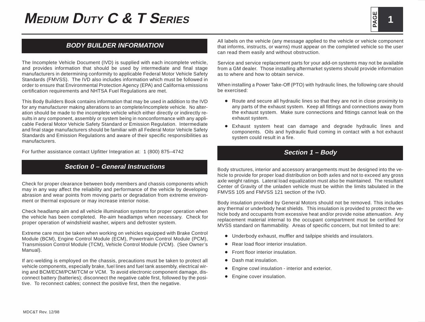
Tire Tread Name: XD2
Description: The drive-axle highway radial especially designed for long, even wear on line-haul 6x4 tractors. The tire also is dramatically improved for much lower rolling resistancewhich improves fuel economy.
Michelin Code: R4L/S4L
LoadDimensions Gross Tire
Max. Pressure Max. Load
Tread RPO SizeLoad
Range/Ply Min. Spac- No Load LoadedGross
Contact RevsTire
Weight Single D al Single D alTreadCode
RPO Size Range/PlyRating
Min. Spacing of Duals Width
(In.)Dia.(In.)
Width(In.)
SLR(In.)
Area(Sq. In.)
RevsPer Mile
Weight(Lbs.)
Single(PSI.)
Dual(PSI.)
Single(Lbs.)
Dual(Lbs.)
S3D YTB 255/70R22.5 H/16 11.1” 9.6” 36.9” 10.6” 17.3” 60.6 561 98 115 115 5510 5070
Tire Tread Name: PXZT
Description: The low profile drive-axle traction radial with mud and snow capabilities.
Michelin Code: R4L/S4L
LoadDimensions Gross Tire
Max. Pressure Max. Load
Tread RPO SizeLoad
Range/Ply Min. Spac- No Load LoadedGross
Contact RevsTire
Weight Single D al Single D alTreadCode
RPO Size Range/PlyRating
Min. Spacing of Duals Width
(In.)Dia.(In.)
Width(In.)
SLR(In.)
Area(Sq. In.)
RevsPer Mile
Weight(Lbs.)
Single(PSI.)
Dual(PSI.)
Single(Lbs.)
Dual(Lbs.)
S3D YTN 225/70R19.5 F/12 9.9” 8.8” 32.5” 9.6” 15.0” 53.3 639 57 85 85 3640 3415
S3D YTY 245/70R19.5 G/14 10.9” 9.7” 33.6” 10.5” 15.6” 55.9 618 72 110 110 4805 4540
Tire Tread Name: XDE A/T
Description: The deep tread, high traction drive tire designed to perform in highway and off road conditions.
Michelin Code: R4L/S4L
LoadDimensions Gross Tire
Max. Pressure Max. Load
Tread RPO SizeLoad
Range/Ply Min. Spac- No Load LoadedGross
Contact RevsTire
Weight Single D al Single D alTreadCode
RPO Size Range/PlyRating
Min. Spacing of Duals Width
(In.)Dia.(In.)
Width(In.)
SLR(In.)
Area(Sq. In.)
RevsPer Mile
Weight(Lbs.)
Single(PSI.)
Dual(PSI.)
Single(Lbs.)
Dual(Lbs.)
R3E/S3E XWP/YWP 12R22.5 H/16 13.0” 11.3” 43.0” 19.8” 486 115 115 7390 6750

PA
GE
19MEDIUM DUTY C & T SERIES
MDC&T Rev. 12/98
Tire Tread Name: XDY-1
Description: The traction directional drive-axle radial truck tire, delivering a new level of balance between traction, mileage, even wear and rolling resistance with versatility for on/offroad use.*
Michelin Code: S4L
LoadDimensions Gross Tire
Max. Pressure Max. Load
Tread RPO SizeLoad
Range/Ply Min. Spac- No Load LoadedGross
Contact RevsTire
Weight Single D al Single D alTreadCode
RPO Size Range/PlyRating
Min. Spacing of Duals Width
(In.)Dia.(In.)
Width(In.)
SLR(In.)
Area(Sq. In.)
RevsPer Mile
Weight(Lbs.)
Single(PSI.)
Dual(PSI.)
Single(Lbs.)
Dual(Lbs.)
S3T YWL 11R22.5 G/14 12.8” 11.3” 42.0” 12.5” 19.6” 84.0 493 138 100 105 6175 5080S3T YWM 11R22.5 H/16 12.8” 11.3” 42.0” 12.4” 19.6” 83.0 493 138 115 115 6610 5850
* Contact Sales Engineering for wheelbase restrictions due to tire tread depth.
Tire Tread Name: XDHT
Description: The drive axle highway radial truck tire that balances long mileage with all-season traction, optimized for high torque applications, like single axle 4x2s.
Michelin Code: R4L/S4L
LoadDimensions Gross Tire
Max. Pressure Max. Load
Tread RPO SizeLoad
Range/Ply Min. Spac- No Load LoadedGross
Contact RevsTire
Weight Single D al Single D alTreadCode
RPO Size Range/PlyRating
Min. Spacing of Duals Width
(In.)Dia.(In.)
Width(In.)
SLR(In.)
Area(Sq. In.)
RevsPer Mile
Weight(Lbs.)
Single(PSI.)
Dual(PSI.)
Single(Lbs.)
Dual(Lbs.)
S3H YWL 11R22.5 G /14 12.6” 11.1” 41.9” 12.0” 19.5” 78.0 500 125 100 105 6175 5080
Tire Tread Name: PXDHT
Description: The low profile drive axle highway radial truck tire that balances long mileage with all-season traction, optimized for high torque applications, like single axle 4x2s.
Michelin Code: R4L/S4L
LoadDimensions Gross Tire
Max. Pressure Max. Load
Tread RPO SizeLoad
Range/Ply Min. Spac- No Load LoadedGross
Contact RevsTire
Weight Single D al Single D alTreadCode
RPO Size Range/PlyRating
Min. Spacing of Duals Width
(In.)Dia.(In.)
Width(In.)
SLR(In.)
Area(Sq. In.)
RevsPer Mile
Weight(Lbs.)
Single(PSI.)
Dual(PSI.)
Single(Lbs.)
Dual(Lbs.)
S3H YSH 275/80R22.5 G /14 12.2” 10.9” 40.7” 12.0” 18.9” 77.3 515 130 100 100 6175 5675

PA
GE20 MEDIUM DUTY C & T SERIES
MDC&T Rev. 12/98
Tire Tread Name: XM+S4
Description: The drive-axle highway radial truck tire with Michelin’s most aggressive tread built for maximum traction in mud and snow.
Michelin Code: R4L/S4L
LoadDimensions Gross Tire
Max. Pressure Max. Load
Tread RPO SizeLoad
Range/Ply Min. Spac- No Load LoadedGross
Contact RevsTire
Weight Single D al Single D alTreadCode
RPO Size Range/PlyRating
Min. Spacing of Duals Width
(In.)Dia.(In.)
Width(In.)
SLR(In.)
Area(Sq. In.)
RevsPer Mile
Weight(Lbs.)
Single(PSI.)
Dual(PSI.)
Single(Lbs.)
Dual(Lbs.)
S3J YUE 9R22.5 F/12 9.8” 8.6” 37.9” 9.6” 17.6” 58.4 548 82 95 95 4540 4300S3J YWK 10R22.5 G/14 10.8” 10.8” 40.2” 10.5” 18.6” 68.0 519 101 105 105 5680 5080
S3J YWL 11R22.5 G/14 11.1” 11.1” 41.7” 12.1” 19.4” 80.0 499 120 105 100 6175 5080S3J YWM 11R22.5 H/16 12.2” 11.2” 41.8” 12.1” 19.4” 79.8 500 121 115 115 6610 5950
S3J YWJ 10R22.5 F/12 10.8” 10.8” 40.2” 10.5” 18.6” 68.0 517 98 95 95 5150 4740
Tire Tread Name: PXM+S4
Description: The low profile drive-axle highway radial truck tire with Michelin’s most aggressive tread built for maximum traction in mud and snow.
Michelin Code: R4L/S4L
LoadDimensions Gross Tire
Max. Pressure Max. Load
Tread RPO SizeLoad
Range/Ply Min. Spac- No Load LoadedGross
Contact RevsTire
Weight Single D al Single D alTreadCode
RPO Size Range/PlyRating
Min. Spacing of Duals Width
(In.)Dia.(In.)
Width(In.)
SLR(In.)
Area(Sq. In.)
RevsPer Mile
Weight(Lbs.)
Single(PSI.)
Dual(PSI.)
Single(Lbs.)
Dual(Lbs.)
S3J YSH 275/80R22.5 G/14 12.3” 11.0” 40.4” 12.0” 18.8” 73.0 516 112 100 100 6175 5675
Tire Tread Name: XZY-1
Description: The low-profile all-wheel-position radial truck tire for on/off road use designed primarily for steering-axle use.
Michelin Code: R4L/S4L
LoadDimensions Gross Tire
Max. Pressure Max. Load
Tread RPO SizeLoad
Range/Ply Min. Spac- No Load LoadedGross
Contact RevsTire
Weight Single D al Single D alTreadCode
RPO Size Range/PlyRating
Min. Spacing of Duals Width
(In.)Dia.(In.)
Width(In.)
SLR(In.)
Area(Sq. In.)
RevsPer Mile
Weight(Lbs.)
Single(PSI.)
Dual(PSI.)
Single(Lbs.)
Dual(Lbs.)
R3K/S3K XWL/YWL 11R22.5 G/14 12.8” 11.3” 41.6” 12.5” 19.5” 81.0 497 126 100 105 6175 5080R3K/S3K XWM/YWM 11R22.5 H/16 12.8” 11.3” 41.6” 12.5” 19.5” 77.0 497 134 115 115 6610 5800
R3K/S3K XWP/YWP 12R22.5 H/16 12.8” 11.3” 42.6” 12.5” 19.8” 486 146 115 115 7390 6610

PA
GE
21MEDIUM DUTY C & T SERIES
MDC&T Rev. 12/98
Goodyear Radial Tires
Tire Tread Name: G291
Description: A rib tire design with traction qualities that permit all-position use.Application: All-position tire for metro service application.
Goodyea r Code: R4A/S4A
LoadDimensions Gross Tire
Max. Pressure Max. Load
Tread RPO SizeLoad
Range/Ply Min. Spac- No Load LoadedGross
Contact RevsTire
Weight Single D al Single D alTreadCode
RPO Size Range/PlyRating
Min. Spacing of Duals Width
(In.)Dia.(In.)
Width(In.)
SLR(In.)
Area(Sq. In.)
RevsPer Mile
Weight(Lbs.)
Single(PSI.)
Dual(PSI.)
Single(Lbs.)
Dual(Lbs.)
R3C XWN 315/80R22.5 J/18 13.8” 12.4” 42.3” 13.5” 19.7” 491 140 120 120 8270 7610
Tire Tread Name: G159
Description: A steel-belt casing, construction ribbed tire designed for commercial applications when added strength and durability are needed.Application: Fast rate of wear steer axles and all-position service.
Goodyea r Code: R4A/S4A
LoadDimensions Gross Tire
Max. Pressure Max. Load
Tread RPO SizeLoad
Range/Ply Min. Spac- No Load LoadedGross
Contact RevsTire
Weight Single D al Single D alTreadCode
RPO Size Range/PlyRating
Min. Spacing of Duals Width
(In.)Dia.(In.)
Width(In.)
SLR(In.)
Area(Sq. In.)
RevsPer Mile
Weight(Lbs.)
Single(PSI.)
Dual(PSI.)
Single(Lbs.)
Dual(Lbs.)
R3C/S3C XTI/YTI 245/70R19.5 F/12 11.0” 9.9” 33.0” 10.9” 15.3” 53 629 74 95 95 4080 3860R3C/S3C XTY/YTY 245/70R19.5 G/14 11.0” 9.9” 33.0” 10.9” 15.3” 53 628 74 100 110 4545 4300R3C/S3C XWL/YWL 11R22.5 G/14 12.6” 10.9” 41.5” 12.0” 19.4” 70 501 118 105 115 6175 5250
R3C/S3C XWM/YWM 11R22.5 H/16 12.6” 10.9” 41.5” 12.0” 19.4” 70 501 128 120 110 6610 5800R3C/S3C XTQ/YTQ 245/75R22.5 G/14 11.0” 9.5” 37.0” 10.4” 17.2” 54 561 88 110 100 4675 4300
R3C/S3C XTU/YTU 265/75R22.5 G/14 11.6” 9.9” 38.7” 10.8” 18.0” 61 537 96 110 100 5205 4805R3C/S3C XRN/YRN 295/75R22.5 G/14 12.9” 11.2” 40.4” 12.3” 18.7” 69 514 118 110 100 6175 5675
R3C/S3C XTB/YTB 255/70R22.5 H/16 11.3” 9.8” 36.4” 10.7” 17.0” 55 571 90 120 115 5510 5070R3C/S3C XWJ/YWJ 10R22.5 F/12 11.4” 10.1” 40.1” 11.0” 18.8” 63 518 105 100 100 5150 4875
R3C/S3C XWP/YWP 12R22.5 H/16 13.5” 11.5” 42.7” 12.7” 19.9” 75 486 152 120 120 7390 6750R3C/S3C XWK/YWK 10R22.5 G/14 11.4” 10.1” 40.1” 11.0” 18.8” 63 518 107 115 105 5250 4970
R3C/S3C XUE/YUE 9R22.5 F/12 10.3” 9.0” 38.4” 9.9” 18.0” 52 541 94 105 95 4500 3950R3C XRV 285/75R24.5 G/14 12.5” 10.9” 41.3” 11.9” 19.4” 69 503 118 110 100 6175 5675
PA
GE22 MEDIUM DUTY C & T SERIES
MDC&T Rev. 12/98
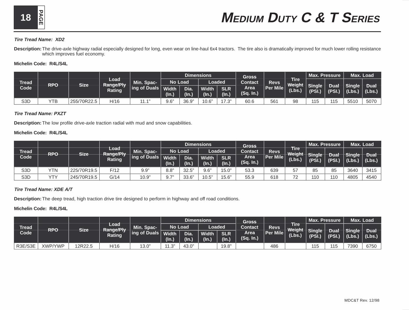
Tire Tread Name: G124
Description: All-season type drive tire developed for maximum traction and tread life under a variety of conditions. Application: Metro and line-haul service, single screw tractors or trucks.
Goodyea r Code: S4A
LoadDimensions Gross Tire
Max. Pressure Max. Load
Tread RPO SizeLoad
Range/Ply Min. Spac- No Load LoadedGross
Contact RevsTire
Weight Single D al Single D alTreadCode
RPO Size Range/PlyRating
Min. Spacing of Duals Width
(In.)Dia.(In.)
Width(In.)
SLR(In.)
Area(Sq. In.)
RevsPer Mile
Weight(Lbs.)
Single(PSI.)
Dual(PSI.)
Single(Lbs.)
Dual(Lbs.)
S3H YTI 245/70R19.5 F/12 11.0” 9.9” 33.2” 10.9” 15.4” 55 622 95 95 85 4080 3875S3H YTY 245/70R19.5 G/14 11.0” 9.9” 33.2” 10.9” 15.4” 55 622 110 110 100 4540 4375
S3H YTU 265/75R22.5 G/14 11.6” 9.9” 38.7” 11.1” 18.2” 63 537 95 110 100 5205 4805S3H YTQ 245/75R22.5 G/14 11.0” 9.5” 37.3” 10.5” 17.4” 56 557 90 110 110 4675 4410
S3H YWL 11R22.5 G/14 12.6” 10.8” 41.7” 11.9” 19.5” 73 498 123 105 115 6175 5250S3H YWM 11R22.5 H/16 12.6” 10.8” 41.7” 11.9” 19.5” 73 498 129 120 110 6610 5800
S3H YRN 295/75R22.5 G/14 12.9” 11.1” 40.6” 12.3” 18.9” 71 512 112 110 100 6175 5675S3H YTB 255/70R22.5 H/16 11.3” 9.8” 36.8” 10.7” 17.2” 53 564 92 115 115 5510 5070S3H YWK 10R22.5 G/14 11.4” 10.0” 40.4” 11.0” 19.0” 67 514 108 115 105 5250 4970
S3H YWJ 10R22.5 F/12 11.4” 10.0” 40.4” 11.0” 19.0” 67 514 108 100 100 5150 4875S3H YWP 12R22.5 H/16 13.5” 11.2” 43.1” 12.4” 20.2” 78 482 151 120 120 7390 6720
S3H YUE 9R22.5 F/12 10.3” 9.0” 38.6” 9.9” 18.1” 53 538 91 105 95 4500 3950S3H YRV 285/75R24.5 G/14 12.5” 10.6” 41.8” 11.9” 19.6” 71 497 117 110 100 6175 5675
Tire Tread Name: G167
Description: The Unisteel G167 rates high in mileage, fuel savings, retreadability and low in tire down time loss. Application: Twin screw tractors or single drive axle service with littleneed for extra traction.
Goodyea r Code: S4A
LoadDimensions Gross Tire
Max. Pressure Max. Load
Tread RPO SizeLoad
Range/Ply Min. Spac- No Load LoadedGross
Contact RevsTire
Weight Single D al Single D alTreadCode
RPO Size Range/PlyRating
Min. Spacing of Duals Width
(In.)Dia.(In.)
Width(In.)
SLR(In.)
Area(Sq. In.)
RevsPer Mile
Weight(Lbs.)
Single(PSI.)
Dual(PSI.)
Single(Lbs.)
Dual(Lbs.)
S3D YWJ 10R22.5 F/12 11.4” 9.9” 40.7” 10.9” 19.1” 65 513 114 100 100 5150 4875S3D YWL 11R22.5 G/14 12.6” 10.7” 42.0” 11.8” 19.7” 73 497 130 105 115 6175 5250
S3D YWM 11R22.5 H/16 12.6” 10.7” 42.0” 11.8” 19.7” 73 497 137 120 110 6610 5800S3D YWP 12R22.5 H/16 13.5” 11.5” 43.2” 12.7” 20.2” 80 483 150 120 120 7390 6750
S3D YRN 295/75R22.5 G/14 12.9” 10.9” 40.8” 11.9” 19.0” 68 512 120 110 100 6175 5675S3D YRV 285/75R24.5 G/14 12.5” 10.5” 42.1” 11.4” 19.7” 74 496 124 110 100 6175 5675

PA
GE
23MEDIUM DUTY C & T SERIES
MDC&T Rev. 12/98
Tire Tread Name: G144
Description: Mixed service high-speed radial truck tire for on/off road applications.
Goodyea r Code: S4A
LoadDimensions Gross Tire
Max. Pressure Max. Load
Tread RPO SizeLoad
Range/Ply Min. Spac- No Load LoadedGross
Contact RevsTire
Weight Single D al Single D alTreadCode
RPO Size Range/PlyRating
Min. Spacing of Duals Width
(In.)Dia.(In.)
Width(In.)
SLR(In.)
Area(Sq. In.)
RevsPer Mile
Weight(Lbs.)
Single(PSI.)
Dual(PSI.)
Single(Lbs.)
Dual(Lbs.)
S3E YWL 11R22.5 G/14 12.6” 10.8” 41.7” 11.9” 19.5” 74 498 124 105 115 6175 5250S3E YWM 11R22.5 H/16 12.6” 10.8” 41.7” 11.9” 19.5” 74 498 132 120 110 6610 5800
Tire Tread Name: G286
Description: For rigorous service as encountered in logging, oil field use, mining areas, and waste haulers. This tire features a 4 rib design and is chip-chunk-cut resistant.Application: Mainly off-the-highway with some over-the-highway service.
Goodyea r Code: R4A/S4A
LoadDimensions Gross Tire
Max. Pressure Max. Load
Tread RPO SizeLoad
Range/Ply Min. Spac- No Load LoadedGross
Contact RevsTire
Weight Single D al Single D alTreadCode
RPO Size Range/PlyRating
Min. Spacing of Duals Width
(In.)Dia.(In.)
Width(In.)
SLR(In.)
Area(Sq. In.)
RevsPer Mile
Weight(Lbs.)
Single(PSI.)
Dual(PSI.)
Single(Lbs.)
Dual(Lbs.)
R3F/S3F XWL/YWL 11R22.5 G/14 12.6” 10.8” 41.7” 11.9” 19.5” 78 496 126 105 115 6040 5250R3F/S3F XWP/YWP 12R22.5 H/16 13.5” 11.4” 43.0” 12.5” 20.0” 81 483 146 120 120 7390 6720
R3F1) XSP 385/65R22.5 J/16 — 14.9” 42.4” 15.9” 19.5” 95 490 181 120 — 9370 —R3F/S3F XWM/YWM 11R22.5 H/16 12.6” 11.0” 41.8” 12.1” 19.5” W/A W/A W/A 120 110 6610 5800
1) Maximum speed 60 mph.

PA
GE24 MEDIUM DUTY C & T SERIES
MDC&T Rev. 12/98
Tire Tread Name: G186
Description: All-position radial truck tire for on/off road service. Wide, flat tread for even wear and long mileage. Application: Mainly over-the-highway with some off-the-highway service.
Goodyear Code: R4A/S4A
LoadDimensions Gross Tire
Max. Pressure Max. Load
Tread RPO SizeLoad
Range/Ply Min. Spac- No Load LoadedGross
Contact RevsTire
Weight Single D al Single D alTreadCode
RPO Size Range/PlyRating
Min. Spacing of Duals Width
(In.)Dia.(In.)
Width(In.)
SLR(In.)
Area(Sq. In.)
RevsPer Mile
Weight(Lbs.)
Single(PSI.)
Dual(PSI.)
Single(Lbs.)
Dual(Lbs.)
R3K/S3K XWJ/YWJ 10R22.5 F/12 11.4” 10.0” 40.4” 11.0” 18.9” 64 514 112 100 100 5150 4875R3K/S3K XWL/YWL 11R22.5 G/14 12.6” 11.0” 41.8” 12.1” 19.5” 70 497 121 105 115 6040 5250
R3K/S3K XWM/YWM 11R22.5 H/16 12.6” 11.0” 41.8” 12.1” 19.5” 70 497 129 120 110 6610 5800
Tire Tread Name: G177
Description: Severe service drive axle radial designed for rugged off-road conditions. Excellent off-road traction and durability.
Goodyea r Code: R4A/S4A
LoadDimensions Gross Tire
Max. Pressure Max. Load
Tread RPO SizeLoad
Range/Ply Min. Spac- No Load LoadedGross
Contact RevsTire
Weight Single D al Single D alTreadCode
RPO Size Range/PlyRating
Min. Spacing of Duals Width
(In.)Dia.(In.)
Width(In.)
SLR(In.)
Area(Sq. In.)
RevsPer Mile
Weight(Lbs.)
Single(PSI.)
Dual(PSI.)
Single(Lbs.)
Dual(Lbs.)
R3L/S3L XWL/YWL 11R22.5 G/14 12.5” 10.9” 42.3” 12.0” 19.7” 75 493 138 105 115 6040 5250
R3L/S3L XWM/YWM 11R22.5 H/16 12.5” 10.9” 42.3” 12.0” 19.7” 75 493 145 120 110 6610 5800R3L/S3L XWP/YWP 12R22.5 H/16 13.5” 11.2” 43.7” 12.3” 20.5” 85 478 160 120 120 7390 6720
Tire Tread Name: G357
Description: High mileage steer tire. Computer-aided tread design for reduced cupping and more even wear. Aggressive five-rib tread design delivers all-weather traction. Re-cessed Pressure Distribution Groove equalizes footprint pressure, reduces tear and stone holding.
Goodyea r Code: R4A/S4A
LoadDimensions Gross Tire
Max. Pressure Max. Load
Tread RPO SizeLoad
Range/Ply Min. Spac- No Load LoadedGross
Contact RevsTire
Weight Single D al Single D alTreadCode
RPO Size Range/PlyRating
Min. Spacing of Duals Width
(In.)Dia.(In.)
Width(In.)
SLR(In.)
Area(Sq. In.)
RevsPer Mile
Weight(Lbs.)
Single(PSI.)
Dual(PSI.)
Single(Lbs.)
Dual(Lbs.)
R3N XWL 11R22.5 G/14 12.5” 10.9” 41.3” 11.9” 19.4” 70 503 120 105 105 6175 5750

PA
GE
25MEDIUM DUTY C & T SERIES
MDC&T Rev. 12/98
General Radial Tires
Tire Tread Name: Ameri-Steel-A-Tread
Description: An all-position, steel-belted radial truck tire that offers excellent tread wear.
General Code: R4H/S4H
LoadDimensions Gross Tire
Max. Pressure Max. Load
Tread RPO SizeLoad
Range/Ply Min. Spac- No Load LoadedGross
Contact RevsTire
Weight Single D al Single D alTreadCode
RPO Size Range/PlyRating
Min. Spacing of Duals Width
(In.)Dia.(In.)
Width(In.)
SLR(In.)
Area(Sq. In.)
RevsPer Mile
Weight(Lbs.)
Single(PSI.)
Dual(PSI.)
Single(Lbs.)
Dual(Lbs.)
R3B/S3B XWL/YWL 11R22.5 G/14 12.6” 10.8” 41.3” 12.2” 19.2” 501 123 105 105 6040 4970
R3B/S3B XWJ/YWJ 10R22.5 F/12 11.4” 10.0” 40.3” 11.3” 18.7” 514 100 100 90 5150 4520
Tire Tread Name: Ameri-Steel-D-Tread
Description: An all-position, steel-belted radial truck tire that offers excellent tread wear.
General Code: R4H/S4H
LoadDimensions Gross Tire
Max. Pressure Max. Load
Tread RPO SizeLoad
Range/Ply Min. Spac- No Load LoadedGross
Contact RevsTire
Weight Single D al Single D alTreadCode
RPO Size Range/PlyRating
Min. Spacing of Duals Width
(In.)Dia.(In.)
Width(In.)
SLR(In.)
Area(Sq. In.)
RevsPer Mile
Weight(Lbs.)
Single(PSI.)
Dual(PSI.)
Single(Lbs.)
Dual(Lbs.)
R3B/S3B XUE/YUE 9R22.5 F/12 10.3” 9.1” 38.2” 10.3” 17.9” 542 79 105 95 4500 3950
R3B XWP 12R22.5 H/16 13.5” 11.9” 42.7” 13.3” 19.8” 485 147 120 7200
Tire Tread Name: Ameri-S380
Description: Premium low profile radial truck tire optimized for steer axles, built for long mileage and retreadability, with versatility for all wheel position use.
General Code: R4H/S4H
LoadDimensions Gross Tire
Max. Pressure Max. Load
Tread RPO SizeLoad
Range/Ply Min. Spac- No Load LoadedGross
Contact RevsTire
Weight Single D al Single D alTreadCode
RPO Size Range/PlyRating
Min. Spacing of Duals Width
(In.)Dia.(In.)
Width(In.)
SLR(In.)
Area(Sq. In.)
RevsPer Mile
Weight(Lbs.)
Single(PSI.)
Dual(PSI.)
Single(Lbs.)
Dual(Lbs.)
R3C XRN 295/75R22.5 G/14 13.2” 11.1” 40.2” 12.0” 18.7” 515 124.8 110 6175
R3C/S3C XWL/YWL 11R22.5 G/14 12.6” 11.0” 41.4” 12.0” 19.3” 500 128.0 105 95 6040 4970

PA
GE26 MEDIUM DUTY C & T SERIES
MDC&T Rev. 12/98
Tire Tread Name: Ameri-S370
Description: Tread compound is specially formulated to provide high mileage for on-highway driving, and resists cuts and tears in off-road use. Visual Alignment Indicators (VAI)aid in early detection of tire tracking problems. Stone Guard System reduces stone retention for casing durability and offers multiple retreading.
General Code: R4H/S4H
LoadDimensions Gross Tire
Max. Pressure Max. Load
Tread RPO SizeLoad
Range/Ply Min. Spac- No Load LoadedGross
Contact RevsTire
Weight Single D al Single D alTreadCode
RPO Size Range/PlyRating
Min. Spacing of Duals Width
(In.)Dia.(In.)
Width(In.)
SLR(In.)
Area(Sq. In.)
RevsPer Mile
Weight(Lbs.)
Single(PSI.)
Dual(PSI.)
Single(Lbs.)
Dual(Lbs.)
R3F XWM 11R22.5 H 12.5” 11.1” 41.4” 12.0” 19.3” 500 119.0 120 110 6610 5800
Tire Tread Name: Ameri-Lug B–Tread
Description: A drive position highway lug tire developed for maximum traction and tread life under a variety of conditions.
General Code: R4H/S4H
LoadDimensions Gross Tire
Max. Pressure Max. Load
Tread RPO SizeLoad
Range/Ply Min. Spac- No Load LoadedGross
Contact RevsTire
Weight Single D al Single D alTreadCode
RPO Size Range/PlyRating
Min. Spacing of Duals Width
(In.)Dia.(In.)
Width(In.)
SLR(In.)
Area(Sq. In.)
RevsPer Mile
Weight(Lbs.)
Single(PSI.)
Dual(PSI.)
Single(Lbs.)
Dual(Lbs.)
S3D YWJ 10R22.5 F/12 11.4” 10.0” 40.3” 11.3” 18.7” 511 106 95 90 5150 4520
Tire Tread Name: Ameri-MSL Radial H–Tread
Description: An all-wheel-position multi-service tire engineered for on or off highway service.
General Code: R4H/S4H
LoadDimensions Gross Tire
Max. Pressure Max. Load
Tread RPO SizeLoad
Range/Ply Min. Spac- No Load LoadedGross
Contact RevsTire
Weight Single D al Single D alTreadCode
RPO Size Range/PlyRating
Min. Spacing of Duals Width
(In.)Dia.(In.)
Width(In.)
SLR(In.)
Area(Sq. In.)
RevsPer Mile
Weight(Lbs.)
Single(PSI.)
Dual(PSI.)
Single(Lbs.)
Dual(Lbs.)
R3K/S3K XWP/YWP 12R22.5 H/16 13.0” 11.3” 42.8” 12.8” 19.6” 484 147 120 110 7200 6320R3K/S3K XWM/YWM 11R22.5 H/16 12.6” 10.7” 41.4” 12.2” 19.3” 500 134 120 110 6610 5800

PA
GE
27MEDIUM DUTY C & T SERIES
MDC&T Rev. 12/98
Bridgestone Radial Tires
Tire Tread Name: R250F (With Side Wall Protector Rib)
Description: This 5 rib all position radial is designed for high scrub applications. The R250F tires feature sidewall protector ribs for cut and abrasion resistance.
Bridgestone Code: R4N/S4N
LoadDimensions Gross Tire
Max. Pressure Max. Load
Tread RPO SizeLoad
Range/Ply Min. Spac- No Load LoadedGross
Contact RevsTire
Weight Single D al Single D alTreadCode
RPO Size Range/PlyRating
Min. Spacing of Duals Width
(In.)Dia.(In.)
Width(In.)
SLR(In.)
Area(Sq. In.)
RevsPer Mile
Weight(Lbs.)
Single(PSI.)
Dual(PSI.)
Single(Lbs.)
Dual(Lbs.)
R3B/S3B XRN/YRN 295/75R22.5 G/14 13.2” 10.9” 40.2” 12.0” 18.8” 519 119 110 100 6175 5675
R3B/S3B XUE/YUE 9R22.5 F/12 10.3” 8.9” 38.3” 9.7” 18.0” 542 91.9 105 95 4500 3950R3B/S3B XWY/YWJ 10R22.5 F/12 11.4” 9.8” 40.0” 10.7” 18.7” 519 107.1 100 90 5150 4520R3B/S3B XWL/YWL 11R22.5 G/14 12.6” 10.7” 41.3” 11.8” 19.3” 502 120.3 105 105 6040 4970
R3B/S3B XWP/YWP 12R22.5 H/16 13.5” 11.6” 42.7” 12.6” 19.8” 487 109.3 120 110 7200 6610R3B/S3B XTQ/YTQ 245/75R22.5 G/14 11.0” 9.7” 37.4” 10.5” 17.6” 555 88.7 110 100 4675 4300
R3B/S3B XTU/YTU 265/75R22.5 G/14 11.6” 10.2” 38.4” 11.1” 18.0” 541 95.9 110 100 5205 4805
Tire Tread Name: R293
Description: Defense groove design for resistance to irregular wear on steering axle positions for on-highway applications. This tire can also be used in drive and trailer positions.
Bridgestone Code: R4N/S4N
LoadDimensions Gross Tire
Max. Pressure Max. Load
Tread RPO SizeLoad
Range/Ply Min. Spac- No Load LoadedGross
Contact RevsTire
Weight Single D al Single D alTreadCode
RPO Size Range/PlyRating
Min. Spacing of Duals Width
(In.)Dia.(In.)
Width(In.)
SLR(In.)
Area(Sq. In.)
RevsPer Mile
Weight(Lbs.)
Single(PSI.)
Dual(PSI.)
Single(Lbs.)
Dual(Lbs.)
R3C/S3C XWL/YWL 11R22.5 G/14 12.6” 10.6” 41.3” 11.7” 19.3” 519 117.4 105 105 6175 5750
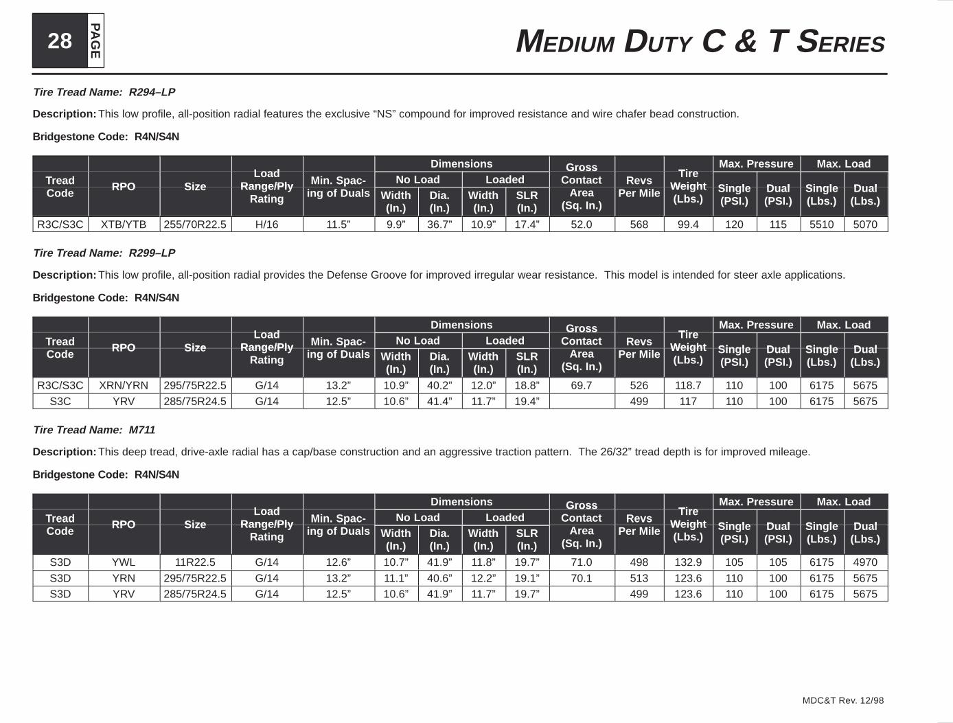
PA
GE28 MEDIUM DUTY C & T SERIES
MDC&T Rev. 12/98
Tire Tread Name: R294–LP
Description: This low profile, all-position radial features the exclusive “NS” compound for improved resistance and wire chafer bead construction.
Bridgestone Code: R4N/S4N
LoadDimensions Gross Tire
Max. Pressure Max. Load
Tread RPO SizeLoad
Range/Ply Min. Spac- No Load LoadedGross
Contact RevsTire
Weight Single D al Single D alTreadCode
RPO Size Range/PlyRating
Min. Spacing of Duals Width
(In.)Dia.(In.)
Width(In.)
SLR(In.)
Area(Sq. In.)
RevsPer Mile
Weight(Lbs.)
Single(PSI.)
Dual(PSI.)
Single(Lbs.)
Dual(Lbs.)
R3C/S3C XTB/YTB 255/70R22.5 H/16 11.5” 9.9” 36.7” 10.9” 17.4” 52.0 568 99.4 120 115 5510 5070
Tire Tread Name: R299–LP
Description: This low profile, all-position radial provides the Defense Groove for improved irregular wear resistance. This model is intended for steer axle applications.
Bridgestone Code: R4N/S4N
LoadDimensions Gross Tire
Max. Pressure Max. Load
Tread RPO SizeLoad
Range/Ply Min. Spac- No Load LoadedGross
Contact RevsTire
Weight Single D al Single D alTreadCode
RPO Size Range/PlyRating
Min. Spacing of Duals Width
(In.)Dia.(In.)
Width(In.)
SLR(In.)
Area(Sq. In.)
RevsPer Mile
Weight(Lbs.)
Single(PSI.)
Dual(PSI.)
Single(Lbs.)
Dual(Lbs.)
R3C/S3C XRN/YRN 295/75R22.5 G/14 13.2” 10.9” 40.2” 12.0” 18.8” 69.7 526 118.7 110 100 6175 5675
S3C YRV 285/75R24.5 G/14 12.5” 10.6” 41.4” 11.7” 19.4” 499 117 110 100 6175 5675
Tire Tread Name: M711
Description: This deep tread, drive-axle radial has a cap/base construction and an aggressive traction pattern. The 26/32” tread depth is for improved mileage.
Bridgestone Code: R4N/S4N
LoadDimensions Gross Tire
Max. Pressure Max. Load
Tread RPO SizeLoad
Range/Ply Min. Spac- No Load LoadedGross
Contact RevsTire
Weight Single D al Single D alTreadCode
RPO Size Range/PlyRating
Min. Spacing of Duals Width
(In.)Dia.(In.)
Width(In.)
SLR(In.)
Area(Sq. In.)
RevsPer Mile
Weight(Lbs.)
Single(PSI.)
Dual(PSI.)
Single(Lbs.)
Dual(Lbs.)
S3D YWL 11R22.5 G/14 12.6” 10.7” 41.9” 11.8” 19.7” 71.0 498 132.9 105 105 6175 4970
S3D YRN 295/75R22.5 G/14 13.2” 11.1” 40.6” 12.2” 19.1” 70.1 513 123.6 110 100 6175 5675S3D YRV 285/75R24.5 G/14 12.5” 10.6” 41.9” 11.7” 19.7” 499 123.6 110 100 6175 5675
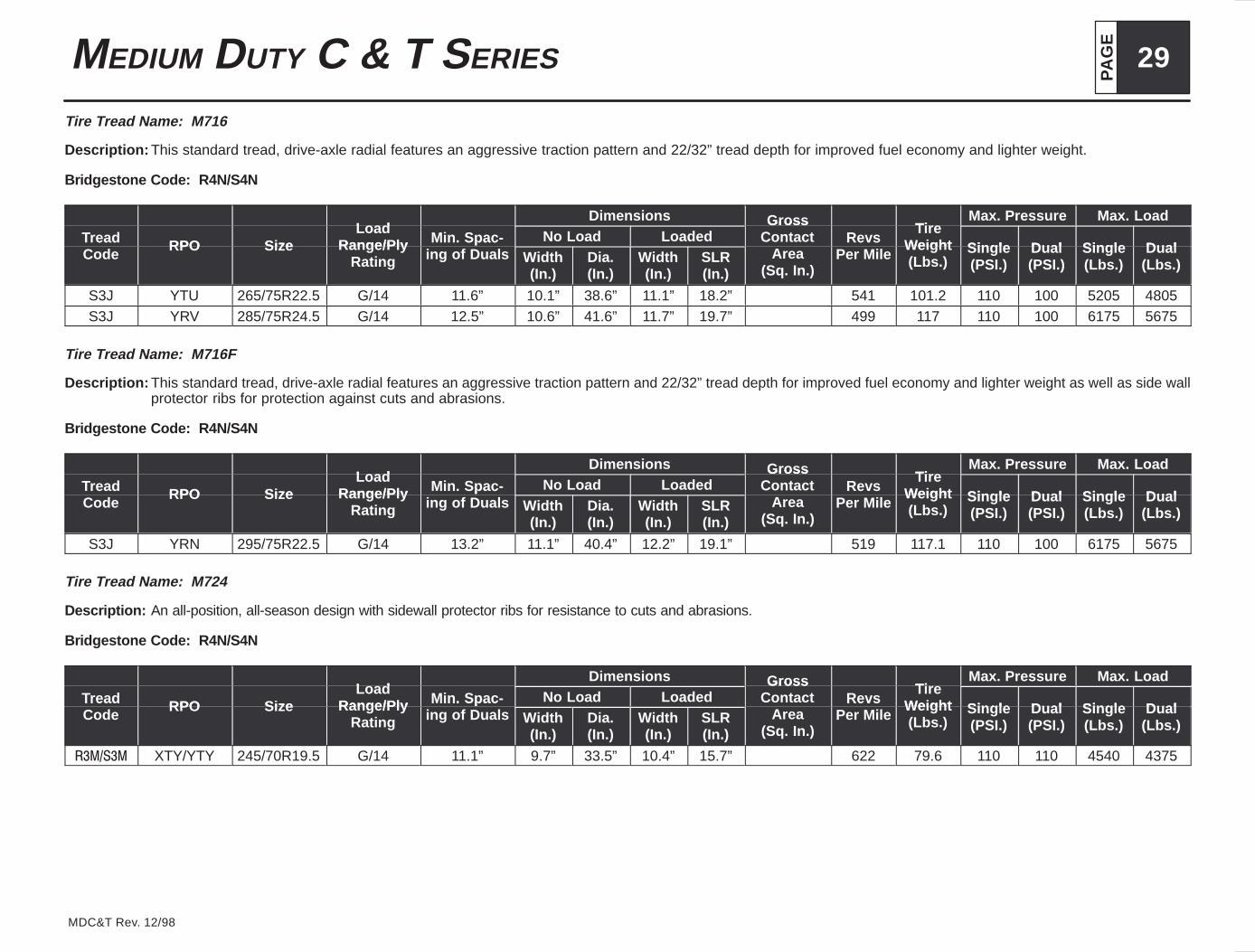
PA
GE
29MEDIUM DUTY C & T SERIES
MDC&T Rev. 12/98
Tire Tread Name: M716
Description: This standard tread, drive-axle radial features an aggressive traction pattern and 22/32” tread depth for improved fuel economy and lighter weight.
Bridgestone Code: R4N/S4N
LoadDimensions Gross Tire
Max. Pressure Max. Load
Tread RPO SizeLoad
Range/Ply Min. Spac- No Load LoadedGross
Contact RevsTire
Weight Single D al Single D alTreadCode
RPO Size Range/PlyRating
Min. Spacing of Duals Width
(In.)Dia.(In.)
Width(In.)
SLR(In.)
Area(Sq. In.)
RevsPer Mile
Weight(Lbs.)
Single(PSI.)
Dual(PSI.)
Single(Lbs.)
Dual(Lbs.)
S3J YTU 265/75R22.5 G/14 11.6” 10.1” 38.6” 11.1” 18.2” 541 101.2 110 100 5205 4805S3J YRV 285/75R24.5 G/14 12.5” 10.6” 41.6” 11.7” 19.7” 499 117 110 100 6175 5675
Tire Tread Name: M716F
Description: This standard tread, drive-axle radial features an aggressive traction pattern and 22/32” tread depth for improved fuel economy and lighter weight as well as side wallprotector ribs for protection against cuts and abrasions.
Bridgestone Code: R4N/S4N
LoadDimensions Gross Tire
Max. Pressure Max. Load
Tread RPO SizeLoad
Range/Ply Min. Spac- No Load LoadedGross
Contact RevsTire
Weight Single D al Single D alTreadCode
RPO Size Range/PlyRating
Min. Spacing of Duals Width
(In.)Dia.(In.)
Width(In.)
SLR(In.)
Area(Sq. In.)
RevsPer Mile
Weight(Lbs.)
Single(PSI.)
Dual(PSI.)
Single(Lbs.)
Dual(Lbs.)
S3J YRN 295/75R22.5 G/14 13.2” 11.1” 40.4” 12.2” 19.1” 519 117.1 110 100 6175 5675
Tire Tread Name: M724
Description: An all-position, all-season design with sidewall protector ribs for resistance to cuts and abrasions.
Bridgestone Code: R4N/S4N
LoadDimensions Gross Tire
Max. Pressure Max. Load
Tread RPO SizeLoad
Range/Ply Min. Spac- No Load LoadedGross
Contact RevsTire
Weight Single D al Single D alTreadCode
RPO Size Range/PlyRating
Min. Spacing of Duals Width
(In.)Dia.(In.)
Width(In.)
SLR(In.)
Area(Sq. In.)
RevsPer Mile
Weight(Lbs.)
Single(PSI.)
Dual(PSI.)
Single(Lbs.)
Dual(Lbs.)
������� XTY/YTY 245/70R19.5 G/14 11.1” 9.7” 33.5” 10.4” 15.7” 622 79.6 110 110 4540 4375

PA
GE30 MEDIUM DUTY C & T SERIES
MDC&T Rev. 12/98
Tire Tread Name: M857
Description: The M857 is a mixed service all-position radial. The rib/lug pattern enables it to be used in steer, drive and trailer axles.
Bridgestone Code: R4N/S4N
LoadDimensions Gross Tire
Max. Pressure Max. Load
Tread RPO SizeLoad
Range/Ply Min. Spac- No Load LoadedGross
Contact RevsTire
Weight Single D al Single D alTreadCode
RPO Size Range/PlyRating
Min. Spacing of Duals Width
(In.)Dia.(In.)
Width(In.)
SLR(In.)
Area(Sq. In.)
RevsPer Mile
Weight(Lbs.)
Single(PSI.)
Dual(PSI.)
Single(Lbs.)
Dual(Lbs.)
R3K/S3K XWK/YWK 10R22.5 G/14 11.4” 9.8” 40.3” 10.8” 19.0” 519 111.3 115 105 5680 4970

PA
GE
31MEDIUM DUTY C & T SERIES
MDC&T Rev. 12/98
PROPELLER SHAFTS
U Joint SeriesTube Diameter (Outside) & Thickness (Inside)
U-Joint SeriesMetric English
JQB 1480JQP 1550JQR 1610JQM 1710
JQQ 1710HDJXD 1760HD
88.9 x 2.1188.9 x 2.4188.9 x 3.40
101.6 x 3.40101.6 x 3.40 DOM
103.9 x 4.57
3.50 x 0.0833.50 x 0.0953.50 x 0.1344.00 x 0.134
4.00 x 0.134 DOM4.09 x 0.180
N/A = Not available RPO driveline combinationManual–Low gear torque = net engine torque (x) low gear (x) transmission efficiencyAutomatic–Low gear torque = net engine torque (x) low gear (x) transmission efficiency (x) torque converter stall ratioTransmission efficiency = 90% manual, 85% automatic
Gas Engines
Engine 210 Net HP @ 3750 RPM7.4L V8 Option LP4
210 Net HP @ 3750 RPM325 lb. ft. of Torque @ 2400 RPM
RPO Transmission Low GearRear Axle (U-Joint Series)
RPO Transmission Low GearTandem 064 Single 042
MF1 AT545 6.76 N/A 1480*ME4 MT643G 11.06 N/A 1610ME6 MT653DRG 24.84 N/A 1610MSC FS4205B 6.99 N/A 1480*MSG FS4205A 8.05 N/A 1550MT9 AT542 6.07 N/A 1480*MMO FS5306 9.01 N/A 1550
* With 23,000 lb. capacity rear axle joint series is upgraded to 1550
Engine 270 HP @ 3750 RPM7.4L V8 Option L21
270 HP @ 3750 RPM390 lb. ft. Torque @ 3200 RPM
RPO Transmission Low GearRear Axle (U-Joint Series)
RPO Transmission Low GearTandem 064 Single 042
ME4 MT643G 11.06 1610 1610
ME6 MT653DRG 24.84 1710HD 1610
MF1 AT545 6.76 N/A 1550
MMO FS5306A 9.01 1610 1550
MNC FS5205B 6.82 1550 1550
MPU FS5205A 7.52 1550 1550
MSC FS4205B 6.99 1550 1550
MSG FS4205A 8.05 N/A 1610
MT9 AT542 6.07 N/A 1550

PA
GE32 MEDIUM DUTY C & T SERIES
MDC&T Rev. 12/98
Diesel Engines
Engine 170 GHP @ 2600 RPM6.6L Diesel Cat. ‘3116’.Option LVR
170 GHP @ 2600 RPM420 lb. ft. Gross Torque @ 1560 RPM
RPO Transmission Low GearRear Axle (U-Joint Series)
RPO Transmission Low GearTandem 064 Single 042
ME3 MT643D 8.77 N/A 1610ME5 MT653DRD 18.09 N/A 1710MF1 AT545 6.76 N/A 1550MK8 ES052-7B 10.09 N/A 1610MMO FS5306A 9.01 N/A 1610MNC FS5205B 6.82 N/A 1550
MNK/MP8 MD3060P 3.49 N/A 1610MPU FS5205A 7.52 N/A 1610MSC FS4205B 6.99 N/A 1550MSG FS4205A 8.05 N/A 1610MT9 AT542 6.07 N/A 1550
MWO FS6206 9.01 N/A 1710
Engine ���#�� �� � ���� ������#�� �� � ���� ���
6.6L Diesel Cat ‘3116’ OptionLVX/LVS/LVT
��� �� �� � ���� ������#��� �� � ���� ���
��� ��� �!� �� ����"� � ���� ��� ���"���� ��� �!� �� ����"� � ���� ��� �"!��
RPO Transmission Low GearRear Axle (U-Joint Series)
RPO Transmission Low GearTandem 064 Single 042
ME3 MT643D 8.77 N/A 1610
ME5 MT653DRD 18.09 N/A 1710
MF1 AT545 6.76 N/A 1610
MK8 ES052-7B 10.09 N/A 1610
MK9 ES066-7B 7.48 N/A 1710
MK0/ML0 FS6305A 7.22 N/A 1610
MMO FS5306A 9.01 N/A 1610
MNC FS5205B 6.82 N/A 1610
MNK/MP8 MD3060P 3.49/2.28 N/A 1710
MNZ/MTP MD3560P 4.59/2.28 N/A 1710
MPU FS5205A 7.52 N/A 1610
MSC FS4205B 6.99 N/A 1550
MSG FS4205A 8.05 N/A 1610
MT9 AT542 6.07 N/A 1610
MUT RT6609 12.72 N/A 1710
MWO FS6306A 9.01 N/A 1710

PA
GE
33MEDIUM DUTY C & T SERIES
MDC&T Rev. 12/98
Engine 215 GHP @ 2600 RPM6.6L Diesel Cat. ‘3116’ Option LVY
215 GHP @ 2600 RPM605 lb. ft. Gross Torque @ 1560 RPM
RPO Transmission Low GearRear Axle (U-Joint Series)
RPO Transmission Low GearTandem 064 Single 042
ME3 MT643D 8.77 1710 1710ME5 MT653DRD 18.09 1710HD 1710HDMK0 FS6205A 7.22 1610 1610MK9 ES066 7.48 1610 1610ML0 FS6205B 7.22 1610 1610
MNK/MP8 MD3060P 3.49/2.28 1710 1710MNZ/MTP MD3560P 4.59/2.28 1710 1710
MUT RT6609 12.72 1710 1710MWO FS6306A 9.01 1710 1710
Engine LQZ - 230 GHP @ 2600 RPM6.6L Diesel Cat. ‘3116’
Option LQZ/LVZ
LQZ 230 GHP @ 2600 RPMLVZ - 250 GHP @ 2600 RPM
650 lb. ft. Gross Torque @ 1560 RPM
RPO Transmission Low GearRear Axle (U-Joint Series)
RPO Transmission Low GearTandem 064 Single 042
ME3 MT643D 8.77 1710HD 1710HD
ME5 MT653DRD 18.09 1710HD 1710HD
MK0 FS6205A 7.22 1610 1610
MK9 ES066 7.48 1710 1710
ML0 FS6205B 7.22 1610 1610
MNK/MP8 MD3060P 3.49/2.28 1710 1710
MNZ/MTP MD3560P 4.59/2.28 1710 1710
MUT RT6609 12.72 1710 1710
MWO FS6306A 9.01 1710 1710
Engine 275 GHP @ 2450 RPM6.6L Diesel Cat. ‘3116’ Option LRU
275 GHP @ 2450 RPM735 lb. ft. Gross Torque @1470 RPM
RPO Transmission Low GearRear Axle (U-Joint Series)
RPO Transmission Low GearTandem 064 Single 042
MNK/MP8 MD3060P 3.49/2.28 1710 1710
MTP/MNZ MD3560P 4.59/2.28 1710 1710
Engine 300 HP @ 2600 RPM6.6L Diesel Cat. ‘3116’ Option LVU
300 HP @ 2600 RPM732 lb. ft. Torque @ 1560 RPM
RPO Transmission Low GearRear Axle (U-Joint Series)
RPO Transmission Low GearTandem 064 Single 042
MNK/MP8 MD3060P 3.49/2.28 1710 1710
MNZ/MTP MD3560P 4.59/2.28 1710 1710
ME2 MD3060P N/A 1710
* With 23,000 lb. capacity rear axle joint series is upgraded to 1550
Engine LG5 175 GHP @ 2200 RPM7.2L Diesel Cat. ‘3126’ Option LSV
175 GHP @ 2200 RPM420 lb. ft. Gross Torque @1440 RPM
RPO Transmission Low GearRear Axle (U-Joint Series)
RPO Transmission Low GearTandem 064 Single 042
ME3 MT643D 8.77 N/A 1610
ME5 MT653DRD 18.09 N/A 1710
MF1 AT545 6.76 N/A 1550
MMO FS5306A 9.01 N/A 1610
MNC FS5205B 6.82 N/A 1550
MNK/MP8 MD3060P 3.49 N/A 1610
MPU FS5205A 7.52 N/A 1610
MSC FS4205B 6.99 N/A 1550
MSG FS4205A 8.55 N/A 1610
MT9 AT542 6.07 N/A 1550
MWO FS6306A 9.01 N/A 1610
MK8 ES052–7B 10.09 N/A 1610
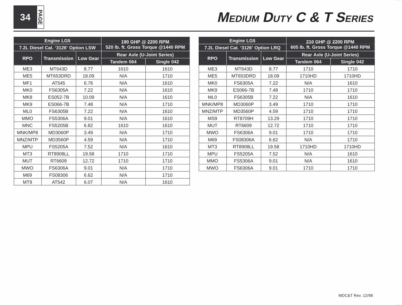
PA
GE34 MEDIUM DUTY C & T SERIES
MDC&T Rev. 12/98
Engine LG5 190 GHP @ 2200 RPM7.2L Diesel Cat. ‘3126’ Option LSW
190 GHP @ 2200 RPM520 lb. ft. Gross Torque @1440 RPM
RPO Transmission Low GearRear Axle (U-Joint Series)
RPO Transmission Low GearTandem 064 Single 042
ME3 MT643D 8.77 1610 1610
ME5 MT653DRD 18.09 N/A 1710
MF1 AT545 6.76 N/A 1610
MK0 FS6305A 7.22 N/A 1610
MK8 ES052-7B 10.09 N/A 1610
MK9 ES066-7B 7.48 N/A 1710
ML0 FS6305B 7.22 N/A 1610
MMO FS5306A 9.01 N/A 1610
MNC FS5205B 6.82 1610 1610
MNK/MP8 MD3060P 3.49 N/A 1710
MNZ/MTP MD3560P 4.59 N/A 1710
MPU FS5205A 7.52 N/A 1610
MT3 RT8908LL 19.58 1710 1710
MUT RT6609 12.72 1710 1710
MWO FS6306A 9.01 N/A 1710
M69 FS08306 6.62 N/A 1710
MT9 AT542 6.07 N/A 1610
Engine LG5 210 GHP @ 2200 RPM7.2L Diesel Cat. ‘3126’ Option LRQ
210 GHP @ 2200 RPM605 lb. ft. Gross Torque @1440 RPM
RPO Transmission Low GearRear Axle (U-Joint Series)
RPO Transmission Low GearTandem 064 Single 042
ME3 MT643D 8.77 1710 1710
ME5 MT653DRD 18.09 1710HD 1710HD
MK0 FS6305A 7.22 N/A 1610
MK9 ES066-7B 7.48 1710 1710
ML0 FS6305B 7.22 N/A 1610
MNK/MP8 MD3060P 3.49 1710 1710
MNZ/MTP MD3560P 4.59 1710 1710
MS9 RT8709H 13.29 1710 1710
MUT RT6609 12.72 1710 1710
MWO FS6306A 9.01 1710 1710
M69 FS08306A 6.62 N/A 1710
MT3 RT8908LL 19.58 1710HD 1710HD
MPU FS5205A 7.52 N/A 1610
MMO FS5306A 9.01 N/A 1610
MWO FS6306A 9.01 1710 1710

PA
GE
35MEDIUM DUTY C & T SERIES
MDC&T Rev. 12/98
Engine LG5 210 GHP @ 2400 RPM7.2L Diesel Cat. ‘3126’ Option LSX
210 GHP @ 2400 RPM520 lb. ft. Gross Torque @1440 RPM
RPO Transmission Low GearRear Axle (U-Joint Series)
RPO Transmission Low GearTandem 064 Single 042
ME3 MT643D 8.77 1610 1610
ME5 MT653DRD 18.09 1710HD 1710HD
MK0 FS6305A 7.22 N/A 1610
MK8 ES052-7B 10.09 N/A 1610
MK9 ES066-7B 7.48 1710 1710
ML0 FS6305B 7.22 N/A 1610
MMO FS5306A 9.01 N/A 1610
MNC FS5205B 6.82 1610 1610
MNK/MP8 MD3060P 3.49 N/A 1710
MNZ/MTP MD3560P 4.59 N/A 1710
MPU FS5205A 7.52 N/A 1610
MT3 RT8908LL 19.58 N/A 1710
MUT RT6609 12.72 1710 1710
MWO FS6306A 9.01 N/A 1710
M69 FS08306A 6.62 N/A N/A
Engine LG5 250 GHP @ 2200 RPM7.2L Diesel Cat. ‘3126’ Option LRR
250 GHP @ 2200 RPM800 lb. ft. Gross Torque @1440 RPM
RPO Transmission Low GearRear Axle (U-Joint Series)
RPO Transmission Low GearTandem 064 Single 042
MNK/MP8 MD3060P 3.49 1710 1710
MNZ/MTP MD3560P 4.59 1710 1710
MS9 RT8709H 13.29 N/A 1710HD
MT3 RT8908LL 19.58 N/A 1710HD
M69 FS08306A 6.62 1710 1710
Engine LG5 250 GHP @ 2200 RPM7.2L Diesel Cat. ‘3126’ Option LQV
250 GHP @ 2200 RPM660 lb. ft. Gross Torque @1440 RPM
RPO Transmission Low GearRear Axle (U-Joint Series)
RPO Transmission Low GearTandem 064 Single 042
ME3 MT643D 8.77 1710HD 1710HD
ME5 MT653DRD 18.09 1710HD 1710HD
MK0 FS6305A 7.22 1610 1610
MK9 ES066-7B 7.48 1610 1610
ML0 FS6305B 7.22 1610 1610
MNK/MP8 MD3060P 3.49 1710 1710
MNZ/MTP MD3560P 4.59 1710 1710
MS9 RT8709H 13.29 1710HD 1710HD
MT3 RT8908LL 19.58 N/A 1710HD
MUT RT6609 12.72 1710 1710
MWO FS6306A 9.01 1710 1710
M69 FS08306A 6.62 1710 1710
Engine LG5 230 GHP @ 2200 RPM7.2L Diesel Cat. ‘3126’ Option LSZ
230 GHP @ 2200 RPM660 lb. ft. Gross Torque @1440 RPM
RPO Transmission Low GearRear Axle (U-Joint Series)
RPO Transmission Low GearTandem 064 Single 042
ME3 MT643D 8.77 1710HD 1710HD
ME5 MT653DRD 18.09 1710HD 1710HD
MK0 FS6305A 7.22 1610 1610
ML0 FS6305B 7.22 1610 1610
MNK/MP8 MD3060P 3.49 1710 1710
MNZ/MTP MD3560P 4.59 1710 1710
MS9 RT8709H 13.29 1710HD 1710HD
MT3 RT8908LL 19.58 N/A 1710HD
MUT RT6609 12.72 1710 1710
MWO FS6306A 9.01 1710 1710
M69 FS08306A 6.62 1710 1710
MK9 ES066–7B 7.48 1710 1710

PA
GE36 MEDIUM DUTY C & T SERIES
MDC&T Rev. 12/98
Engine LG5 275 GHP @ 2200 RPM7.2L Diesel Cat. ‘3126’ Option LQW
275 GHP @ 2200 RPM800 lb. ft. Gross Torque @1440 RPM
RPO Transmission Low GearRear Axle (U-Joint Series)
RPO Transmission Low GearTandem 064 Single 042
MNK/MP8 MD3060P 3.49 1710 1710
MNZ/MTP MD3560P 4.59 1710 1710
MS9 RT8709H 13.29 N/A N/A
MT3 RT8908LL 19.58 N/A 1710HD
M69 FS08306A 6.62 1710 1710
Engine LG5 275 GHP @ 2200 RPM7.2L Diesel Cat. ‘3126’ Option LRS
275 GHP @ 2200 RPM860 lb. ft. Gross Torque @1440 RPM
RPO Transmission Low GearRear Axle (U-Joint Series)
RPO Transmission Low GearTandem 064 Single 042
MNK/MP8 MD3060P 3.49 1710 1710
MNZ/MTP MD3560P 4.59 1710 1710
MS9 RT8709H 13.29 N/A 1710HD
MT3 RT8908LL 19.58 N/A 1710HD
Engine LG5 300 GHP @ 2200 RPM7.2L Diesel Cat. ‘3126’ Option LQX
300 GHP @ 2200 RPM800 lb. ft. Gross Torque @1440 RPM
RPO Transmission Low GearRear Axle (U-Joint Series)
RPO Transmission Low GearTandem 064 Single 042
MNK/MP8 MD3060P 3.49 1710 1710
MNZ/MTP MD3560P 4.59 1710 1710
MS9 RT8709H 13.29 N/A 1710HD
MT3 RT8908LL 19.58 N/A 1710HD
M69 FS08306A 6.62 1710 1710
Engine LG5 300 GHP @ 2200 RPM7.2L Diesel Cat. ‘3126’ Option LRT
300 GHP @ 2200 RPM860 lb. ft. Gross Torque @1440 RPM
RPO Transmission Low GearRear Axle (U-Joint Series)
RPO Transmission Low GearTandem 064 Single 042
MNK/MP8 MD3060P 3.49 1710 1710
MNZ/MTP MD3560P 4.59 1710 1710
MS9 RT8709H 13.29 N/A 1710HD
MT3 RT8908LL 19.58 N/A 1710HD
Engine LG4 200 GHP @ 2400 RPM7.8L Diesel Option LQB
200 GHP @ 2400 RPM452 lb. ft. Gross Torque @1500 RPM
RPO Transmission Low GearRear Axle (U-Joint Series)
RPO Transmission Low GearTandem 064 Single 042
M54 MLD6Q 6.72 N/A 1550
MF1 AT545 6.76 N/A 1550
Engine LG4 230 GHP @ 2400 RPM7.8L Diesel Option LQC
230 GHP @ 2400 RPM517 lb. ft. Gross Torque @1500 RPM
RPO Transmission Low GearRear Axle (U-Joint Series)
RPO Transmission Low GearTandem 064 Single 042
M54 MLD6Q 6.72 N/A 1610

PA
GE
37MEDIUM DUTY C & T SERIES
MDC&T Rev. 12/98
U–Joint Angle and Equivalent Cancellation

PA
GE38 MEDIUM DUTY C & T SERIES
MDC&T Rev. 12/98
Typical Installation Showing Yokes in Phase
![ADVISORY - GM UPFITTER Bulletin 124b.pdf · ADVISORY: Condition/Concern: Trucks equipped with option VYU [Snow Plow Prep] ... may exhibit occurrences in which the Instrument Panel](https://img.pdfslide.net/doc/110x75/5b3856097f8b9a5f288f09bd/advisory-gm-upfitter-bulletin-124bpdf-advisory-conditionconcern-trucks.jpg)


![1999 Diesel GM Medium Duty Electrical Manual[1]](https://img.pdfslide.net/doc/110x75/577d24dc1a28ab4e1e9d934f/1999-diesel-gm-medium-duty-electrical-manual1.jpg)