Embed Size (px)
Citation preview
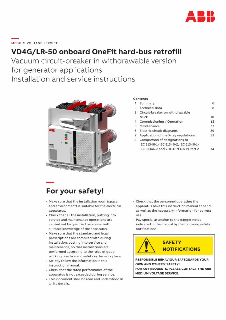
—For your safety!• Make sure that the installation room (space
and environment) is suitable for the electrical apparatus.
• Check that all the installation, putting into service and maintenance operations are carried out by qualified personnel with suitable knowledge of the apparatus.
• Make sure that the standard and legal prescriptions are complied with during installation, putting into service and maintenance, so that installations are performed according to the rules of good working practice and safety in the work place.
• Strictly follow the information in this instruction manual.
• Check that the rated performance of the apparatus is not exceeded during service.
• This document shall be read and understood in all its details.
Contents 1 Summary 6 2 Technical data 8 3 Circuit-breaker on withdrawable
truck 10 4 Commissioning / Operation 12 5 Maintenance 17 6 Electric circuit diagrams 29 7 Application of the X-ray regulations 33 8 Comparison of designations to IEC 81346-1/IEC 81346-2, IEC 61346-1/ IEC 61346-2 and VDE-DIN 40719 Part 2 34
— M ED I U M VO LTAG E S ERV I CE
VD4G/LR-50 onboard OneFit hard-bus retrofillVacuum circuit-breaker in withdrawable versionfor generator applications Installation and service instructions
• Check that the personnel operating the apparatus have this instruction manual at hand as well as the necessary information for correct use.
• Pay special attention to the danger notes indicated in the manual by the following safety notifications:
RESPONSIBLE BEHAVIOUR SAFEGUARDS YOUR OWN AND OTHERS’ SAFETY!FOR ANY REQUESTS, PLEASE CONTACT THE ABB MEDIUM VOLTAGE SERVICE.
SAFETYNOTIFICATIONS
2 V D 4 G/LR- 5 0 O N B OA R D O N E F IT H A R D - B U S R E TRO F I LL - I NS TA L L ATI O N A N D SER V I CE I NS TR U C TI O NS
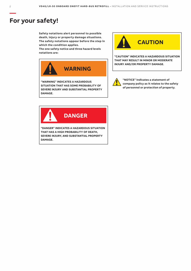
“NOTICE” indicates a statement of company policy as it relates to the safety of personnel or protection of property.
Safety notations alert personnel to possible death, injury or property damage situations. The safety notations appear before the step in which the condition applies. The one safety notice and three hazard levels notations are:
“WARNING” INDICATES A HAZARDOUS SITUATION THAT HAS SOME PROBABILITY OF SEVERE INJURY AND SUBSTANTIAL PROPERTY DAMAGE.
“DANGER” INDICATES A HAZARDOUS SITUATION THAT HAS A HIGH PROBABILITY OF DEATH, SEVERE INJURY, AND SUBSTANTIAL PROPERTY DAMAGE.
“CAUTION” INDICATES A HAZARDOUS SITUATION THAT MAY RESULT IN MINOR OR MODERATE INJURY AND/OR PROPERTY DAMAGE.
—For your safety!
DANGER
WARNING
CAUTION
M ED I U M VO LTAG E S ER V I CE 3
—I. Introduction
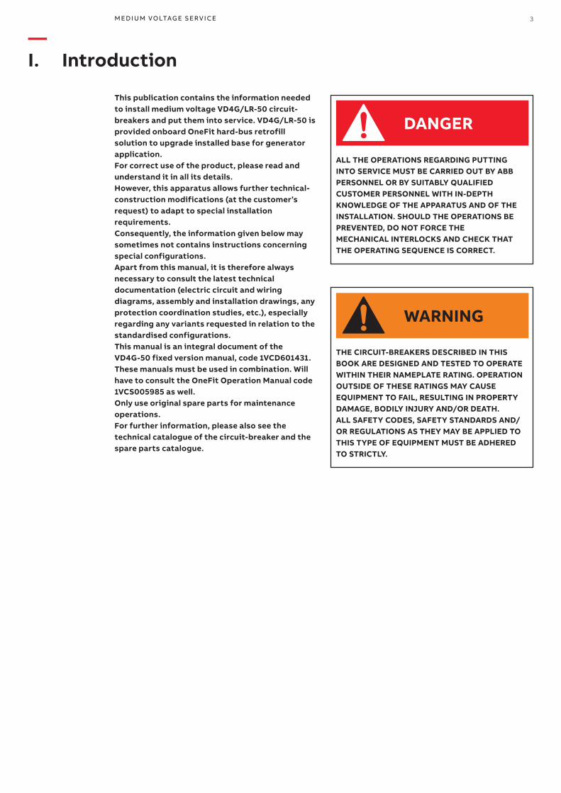
This publication contains the information needed to install medium voltage VD4G/LR-50 circuit-breakers and put them into service. VD4G/LR-50 is provided onboard OneFit hard-bus retrofill solution to upgrade installed base for generator application.For correct use of the product, please read and understand it in all its details.However, this apparatus allows further technical-construction modifications (at the customer’s request) to adapt to special installation requirements.Consequently, the information given below may sometimes not contains instructions concerning special configurations.Apart from this manual, it is therefore always necessary to consult the latest technical documentation (electric circuit and wiring diagrams, assembly and installation drawings, any protection coordination studies, etc.), especially regarding any variants requested in relation to the standardised configurations.This manual is an integral document of the VD4G-50 fixed version manual, code 1VCD601431. These manuals must be used in combination. Will have to consult the OneFit Operation Manual code 1VCS005985 as well.Only use original spare parts for maintenance operations.For further information, please also see the technical catalogue of the circuit-breaker and the spare parts catalogue.
ALL THE OPERATIONS REGARDING PUTTING INTO SERVICE MUST BE CARRIED OUT BY ABB PERSONNEL OR BY SUITABLY QUALIFIED CUSTOMER PERSONNEL WITH IN-DEPTH KNOWLEDGE OF THE APPARATUS AND OF THE INSTALLATION. SHOULD THE OPERATIONS BE PREVENTED, DO NOT FORCE THE MECHANICAL INTERLOCKS AND CHECK THAT THE OPERATING SEQUENCE IS CORRECT.
THE CIRCUIT-BREAKERS DESCRIBED IN THIS BOOK ARE DESIGNED AND TESTED TO OPERATE WITHIN THEIR NAMEPLATE RATING. OPERATION OUTSIDE OF THESE RATINGS MAY CAUSE EQUIPMENT TO FAIL, RESULTING IN PROPERTY DAMAGE, BODILY INJURY AND/OR DEATH.ALL SAFETY CODES, SAFETY STANDARDS AND/OR REGULATIONS AS THEY MAY BE APPLIED TO THIS TYPE OF EQUIPMENT MUST BE ADHERED TO STRICTLY.
DANGER
WARNING

4 V D 4 G/LR- 5 0 O N B OA R D O N E F IT H A R D - B U S R E TRO F I LL - I NS TA L L ATI O N A N D SER V I CE I NS TR U C TI O NS
The VD4G/LR-50 circuit-breakers are manufactured in accordance with the ISO 14000 Standards (Guidelines for environmental management).The production processes are carried out in compliance with the Standards for environmental protection in terms of reduction in energy consumption as well as in raw materials and production of waste materials. All this is thanks to the medium voltage apparatus manufacturing facility environmental management system.
—II. Environmental protection programme
M ED I U M VO LTAG E S ER V I CE 5
We reserve all rights to this publication. Misuse, particularly including duplication and making available of this manual– or extracts – to third parties is prohibited. The information supplied is without liability. Subject to alteration.
—Contents
1 Summary 6 1.1 General 6 1.2 Standards and specifications 6 1.2.1 Reference Standards 6 1.2.2 Installation and operation 6 1.3 Operating conditions 7 1.3.1 Normal operating conditions 7 1.3.2 Special operating conditions 7 2 Technical data 8 2.1 Technical data of the generator circuit-breaker 8 3 Circuit-breaker on withdrawable truck 10 3.1 Basic structure 10 3.2 Interlocks / protection against malfunction 10 3.2.1 Basic equipment 11 4 Commissioning / Operation 12 4.1 Notes for safety at work 12 4.2 Preparatory work 12 4.3 Start-up 13 4.4 Moving the withdrawable circuit-breaker 14 4.4.1 Manual insertion from the test/disconnected position to the service position 14 4.4.2 Manual withdrawal from the service position into the test/disconnected position 14 4.4.3 Motor-driven movement of the withdrawable truck 15 4.5 Circui-breaker operation 15 4.5.1 Charging the stored-energy spring system 15 4.5.2 Opening and closing the circuit-breaker 16 4.5.3 VD4G/LR-50 circuit-breaker run-on block 16 5 Maintenance 17 5.1 General 17 5.2 Service life 18 5.3 Inspection and functional testing 18 5.3.1 General 18 5.3.2 Withdrawable assembly 18 5.4 Servicing 19 5.5 Repairs 20 5.5.1 Repair of surface damage 20 5.5.2 Replacement of withdrawable assembly 20 5.6 Testing withdrawable truck of a VD4G/LR-50 type circuit-breaker 21 5.6.1 Motor-driven withdrawable truck 21 5.6.2 Checking the correctness of dimensional settings 21 5.6.3 Checking auxiliary switch settings on type A withdrawable truck 21 5.6.4 Checking auxiliary switch settings on type B withdrawable truck 21 5.6.5 Checking the direction of rotation of the travel motors on motor-driven withdrawable
versions 22 5.6.6 Testing of interlock conditions 22 5.7 Spare parts, auxiliary materials, lubricants 23 5.7.1 Spare parts 23 5.8 Wiring diagrams for circuit-breakers on withdrawable truck 30 6 Application of the X-ray regulations 34 7 Comparison of designations to IEC 81346-1/IEC 81346-2, IEC 61346-1/IEC 61346-2 and VDE-DIN 40719 Part 2 35
6 V D 4 G/LR- 5 0 O N B OA R D O N E F IT H A R D - B U S R E TRO F I LL - I NS TA L L ATI O N A N D SER V I CE I NS TR U C TI O NS
—1 Summary
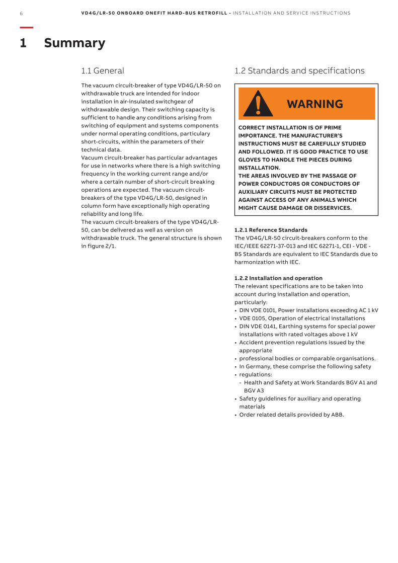
1.1 General
The vacuum circuit-breaker of type VD4G/LR-50 on withdrawable truck are intended for indoor installation in air-insulated switchgear of withdrawable design. Their switching capacity is sufficient to handle any conditions arising from switching of equipment and systems components under normal operating conditions, particulary short-circuits, within the parameters of their technical data.Vacuum circuit-breaker has particular advantages for use in networks where there is a high switching frequency in the working current range and/or where a certain number of short-circuit breaking operations are expected. The vacuum circuit-breakers of the type VD4G/LR-50, designed in column form have exceptionally high operating reliability and long life.The vacuum circuit-breakers of the type VD4G/LR-50, can be delivered as well as version on withdrawable truck. The general structure is shown in figure 2/1.
1.2.1 Reference StandardsThe VD4G/LR-50 circuit-breakers conform to the IEC/IEEE 62271-37-013 and IEC 62271-1, CEI - VDE - BS Standards are equivalent to IEC Standards due to harmonization with IEC.
1.2.2 Installation and operationThe relevant specifications are to be taken into account during installation and operation, particularly:• DIN VDE 0101, Power installations exceeding AC 1 kV• VDE 0105, Operation of electrical installations• DIN VDE 0141, Earthing systems for special power
installations with rated voltages above 1 kV• Accident prevention regulations issued by the
appropriate• professional bodies or comparable organisations.• In Germany, these comprise the following safety• regulations:
- Health and Safety at Work Standards BGV A1 and BGV A3
• Safety guidelines for auxiliary and operating materials
• Order related details provided by ABB.
CORRECT INSTALLATION IS OF PRIME IMPORTANCE. THE MANUFACTURER’S INSTRUCTIONS MUST BE CAREFULLY STUDIED AND FOLLOWED. IT IS GOOD PRACTICE TO USE GLOVES TO HANDLE THE PIECES DURING INSTALLATION. THE AREAS INVOLVED BY THE PASSAGE OF POWER CONDUCTORS OR CONDUCTORS OF AUXILIARY CIRCUITS MUST BE PROTECTED AGAINST ACCESS OF ANY ANIMALS WHICH MIGHT CAUSE DAMAGE OR DISSERVICES.
1.2 Standards and specifications
WARNING
M ED I U M VO LTAG E S ER V I CE 7
1.3 Operating conditions
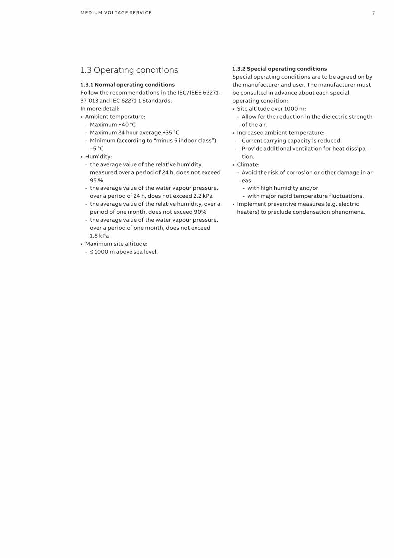
1.3.1 Normal operating conditionsFollow the recommendations in the IEC/IEEE 62271-37-013 and IEC 62271-1 Standards.In more detail:• Ambient temperature:
- Maximum +40 °C - Maximum 24 hour average +35 °C - Minimum (according to “minus 5 indoor class”)
–5 °C• Humidity:
- the average value of the relative humidity, measured over a period of 24 h, does not exceed 95 %
- the average value of the water vapour pressure, over a period of 24 h, does not exceed 2.2 kPa
- the average value of the relative humidity, over a period of one month, does not exceed 90%
- the average value of the water vapour pressure, over a period of one month, does not exceed 1.8 kPa
• Maximum site altitude: - ≤ 1000 m above sea level.
1.3.2 Special operating conditionsSpecial operating conditions are to be agreed on by the manufacturer and user. The manufacturer must be consulted in advance about each special operating condition:• Site altitude over 1000 m:
- Allow for the reduction in the dielectric strength of the air.
• Increased ambient temperature: - Current carrying capacity is reduced - Provide additional ventilation for heat dissipa-
tion.• Climate:
- Avoid the risk of corrosion or other damage in ar-eas:
- with high humidity and/or - with major rapid temperature fluctuations.
• Implement preventive measures (e.g. electric heaters) to preclude condensation phenomena.
8 V D 4 G/LR- 5 0 O N B OA R D O N E F IT H A R D - B U S R E TRO F I LL - I NS TA L L ATI O N A N D SER V I CE I NS TR U C TI O NS
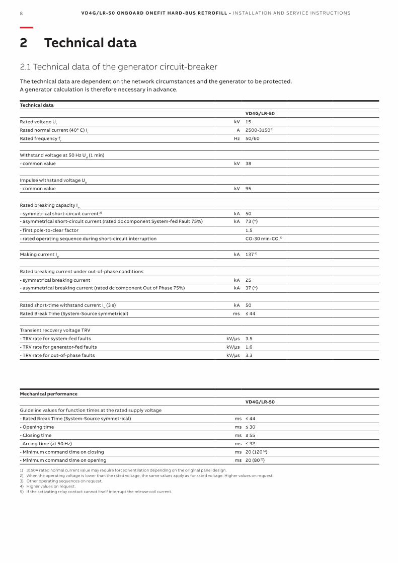
1) 3150A rated normal current value may require forced ventilation depending on the original panel design.2) When the operating voltage is lower than the rated voltage, the same values apply as for rated voltage. Higher values on request.3) Other operating sequences on request.4) Higher values on request.5) If the activating relay contact cannot itself interrupt the release coil current.
Mechanical performance
VD4G/LR-50
Guideline values for function times at the rated supply voltage
- Rated Break Time (System-Source symmetrical) ms ≤ 44
- Opening time ms ≤ 30
- Closing time ms ≤ 55
- Arcing time (at 50 Hz) ms ≤ 32
- Minimum command time on closing ms 20 (120 5))
- Minimum command time on opening ms 20 (80 5))
Technical data
VD4G/LR-50
Rated voltage Ur kV 15
Rated normal current (40° C) Ir A 2500-3150 1)
Rated frequency fr Hz 50/60
Withstand voltage at 50 Hz Ud (1 min)
- common value kV 38
Impulse withstand voltage Up
- common value kV 95
Rated breaking capacity Isc
- symmetrical short-circuit current 2) kA 50
- asymmetrical short-circuit current (rated dc component System-fed Fault 75%) kA 73 (*)
- first pole-to-clear factor 1.5
- rated operating sequence during short-circuit interruption CO-30 min-CO 3)
Making current Ip kA 137 4)
Rated breaking current under out-of-phase conditions
- symmetrical breaking current kA 25
- asymmetrical breaking current (rated dc component Out of Phase 75%) kA 37 (*)
Rated short-time withstand current Ik (3 s) kA 50
Rated Break Time (System-Source symmetrical) ms ≤ 44
Transient recovery voltage TRV
- TRV rate for system-fed faults kV/µs 3.5
- TRV rate for generator-fed faults kV/µs 1.6
- TRV rate for out-of-phase faults kV/µs 3.3
—2 Technical data
2.1 Technical data of the generator circuit-breaker
The technical data are dependent on the network circumstances and the generator to be protected. A generator calculation is therefore necessary in advance.
124 36
35
43 36
585 653
636
0 22
157 175 307
353 384 393 424
325
15
8
310
2
80
21,
5
25 320
74,3
698
52
382,3
678
697
598
698
130 125
306
10
9
210 210
16
650
16
55
M ED I U M VO LTAG E S ER V I CE 9
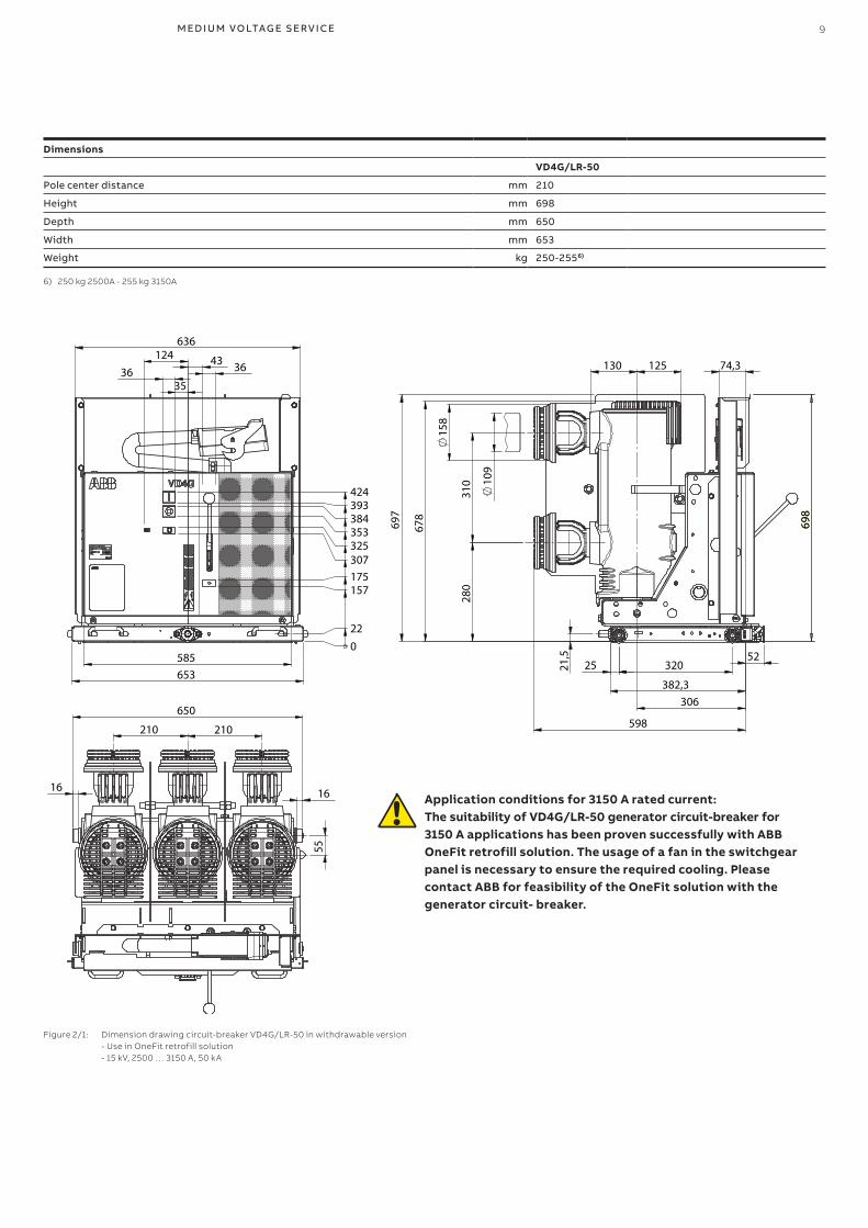
6) 250 kg 2500A - 255 kg 3150A
Dimensions
VD4G/LR-50
Pole center distance mm 210
Height mm 698
Depth mm 650
Width mm 653
Weight kg 250-2556)
Application conditions for 3150 A rated current: The suitability of VD4G/LR-50 generator circuit-breaker for
3150 A applications has been proven successfully with ABB OneFit retrofill solution. The usage of a fan in the switchgear panel is necessary to ensure the required cooling. Please contact ABB for feasibility of the OneFit solution with the generator circuit- breaker.
Figure 2/1: Dimension drawing circuit-breaker VD4G/LR-50 in withdrawable version - Use in OneFit retrofill solution - 15 kV, 2500 … 3150 A, 50 kA
10 V D 4 G/LR- 5 0 O N B OA R D O N E F IT H A R D - B U S R E TRO F I LL - I NS TA L L ATI O N A N D SER V I CE I NS TR U C TI O NS
—3. Circuit-breaker on withdrawable truck
3.1 Basic structure (Figures 3/1 to 3/3, 4/1, 4/2 and 5/1)
The withdrawable truck, which can be moved manually or by a motor if fitted, consists of a steel sheet structure on which the circuit-breaker with its ancillary components is mounted.Insulated contact arms (4.2) with the spring-loaded contact systems are fitted to the circuit-breaker poles. These create the electrical connection to the panel when the withdrawable truck is inserted into the service position. A multi-pole control wiring plug connector (10) connects the signalling, protection and control wiring between the panel and the withdrawable truck.The withdrawable assembly and the circuit-breaker are connected via a multi-pole control wiring plug connector (10.3).As soon as the withdrawable truck (13) has been slid into the panel and its base frame has engaged in the test/disconnected position, it is positively connected to the panel. At the same time, it is earthed by its travel rollers in their rails. The stored-energy spring mechanism of the circuit-breaker, including its controls and indicators, is accessible at the front of the withdrawable truck.
3.2 Interlocks / protection against malfunction
A series of interlocks are provided to prevent dangerous situations and any malfunction. The interlocks of the OneFit retrofill solution and/or the mounting frame, which are normally effective, are as follows (concerning the circuit-breaker):The withdrawable truck can only be moved from the test/disconnected position into the service position (and back) with the circuit-breaker open and the earthing switch open (if any - that means that the breaker must be opened before).The circuit-breaker can only be closed when the withdrawable truck is precisely in the defined test position or service position (mechanical inter lock, with additional electrical interlock for circuit-breakers with electrical releases).The circuit-breaker can only be opened manually in the service or test position when no control voltage is applied, and cannot be closed (electromechanical interlock).Connection and disconnection of the control wiring plug connector (10.2) is possible only in the test/disconnected position.The earthing switch (if any) can only be closed when the withdrawable truck is in the test/disconnected position or the removed position (mechanical interlock).The withdrawable truck cannot be moved from the test/disconnected position into the service position when the earthing switch is closed (mechanical interlock).Details of the OneFit retrofill solution interlocks are available on OneFit Operation Manual code 1VCS005985.Details of any additional interlocks, e.g. in connection with a blocking magnet on the withdrawable truck and/or earthing switch operating mechanism, can be found in the order documents for each individual case (see also section 5.5.Details of typical interlocks for the panels can be found in the panel documentation.
MODIFICATION TO INTERLOCKS CAN RESULT IN HAZARDOUS CONDITIONS TO PERSONNEL AND EQUIPMENT. DO NOT OVERRIDE, BY PASS OR ADJUST INTERLOCKS.
DANGER
18.218 -BGT1 -BGT2 10.3
13.9 4.213.13 4.3 10.2 13.6 13.7
M ED I U M VO LTAG E S ER V I CE 11
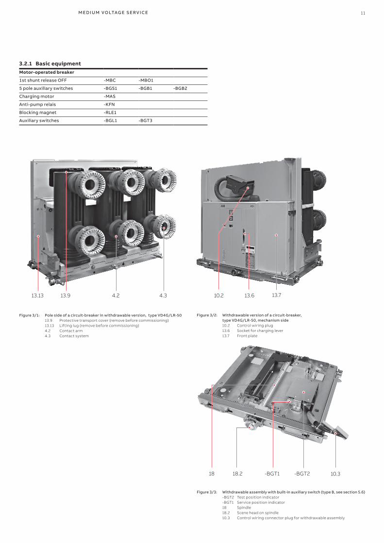
3.2.1 Basic equipmentMotor-operated breaker
1st shunt release OFF -MBC -MBO1
5 pole auxiliary switches -BGS1 -BGB1 -BGB2
Charging motor -MAS
Anti-pump relais -KFN
Blocking magnet -RLE1
Auxiliary switches -BGL1 -BGT3
Figure 3/1: Pole side of a circuit-breaker in withdrawable version, type VD4G/LR-50 13.9 Protective transport cover (remove before commissioning) 13.13 Lifting lug (remove before commissioning) 4.2 Contact arm 4.3 Contact system
Figure 3/2: Withdrawable version of a circuit-breaker, type VD4G/LR-50, mechanism side 10.2 Control wiring plug 13.6 Socket for charging lever 13.7 Front plate
Figure 3/3: Withdrawable assembly with built-in auxiliary switch (type B, see section 5.6) -BGT2 Test position indicator -BGT1 Service position indicator 18 Spindle 18.2 Scene head on spindle 10.3 Control wiring connector plug for withdrawable assembly
12 V D 4 G/LR- 5 0 O N B OA R D O N E F IT H A R D - B U S R E TRO F I LL - I NS TA L L ATI O N A N D SER V I CE I NS TR U C TI O NS
—4. Commissioning / Operation
• The switchgear and OneFit retrofill solution may only be operated by specially trained personnel who are familiar with the characteristics of the particular device.
• Observe the relevant instructions in section 1.2.• Due to safety reasons, the circuit-breaker has to
be treated as “switched on” if the switching position can not be clearly determinated.
• In this case all high voltage connections to the breaker must be de-energized and zero potential on the primary side of the breaker has to be confirmed prior to commissioning, operation, maintenance or repair work.
4.2 Preparatory work (Figure 3/1 and 3/3)
In preparation for commissioning, the following work should be carried out prior to connection with the high-voltage power supply:• Check the general condition of the switchgear and
the OneFit retrofill solution for detrimental circumstances of all kinds.
• Perform a visual examination of the switching devices, withdrawable parts, isolating contacts, insulating parts, etc.
• Check primary and secondary connections as well as earthing conductor.
• Check the connection of the main earthing bar with the station earthing conductor (DIN VDE 0141).
• Check the paintwork for damage and touch up as described in section 5.5 where necessary.
• Remove all material residues, foreign bodies and tools from the switchgear and OneFit retrofill solution.
• Clean the switchgear and OneFit retrofill solution, rubbing down insulating parts with a clean, soft, non-fraying and dry cloth. Remove greasy or adhesive dirt as described in section 5.3.
• Properly refit all covers, etc., removed during assembly and testing processes.
• Transport caps (13.9) on the poles of vacuum circuit breakers, where fitted, must be removed (Fig. 3/1).
• Lifting lugs (13.13) for high current circuit-breakers, if still fitted, must be removed (Fig. 3.1).
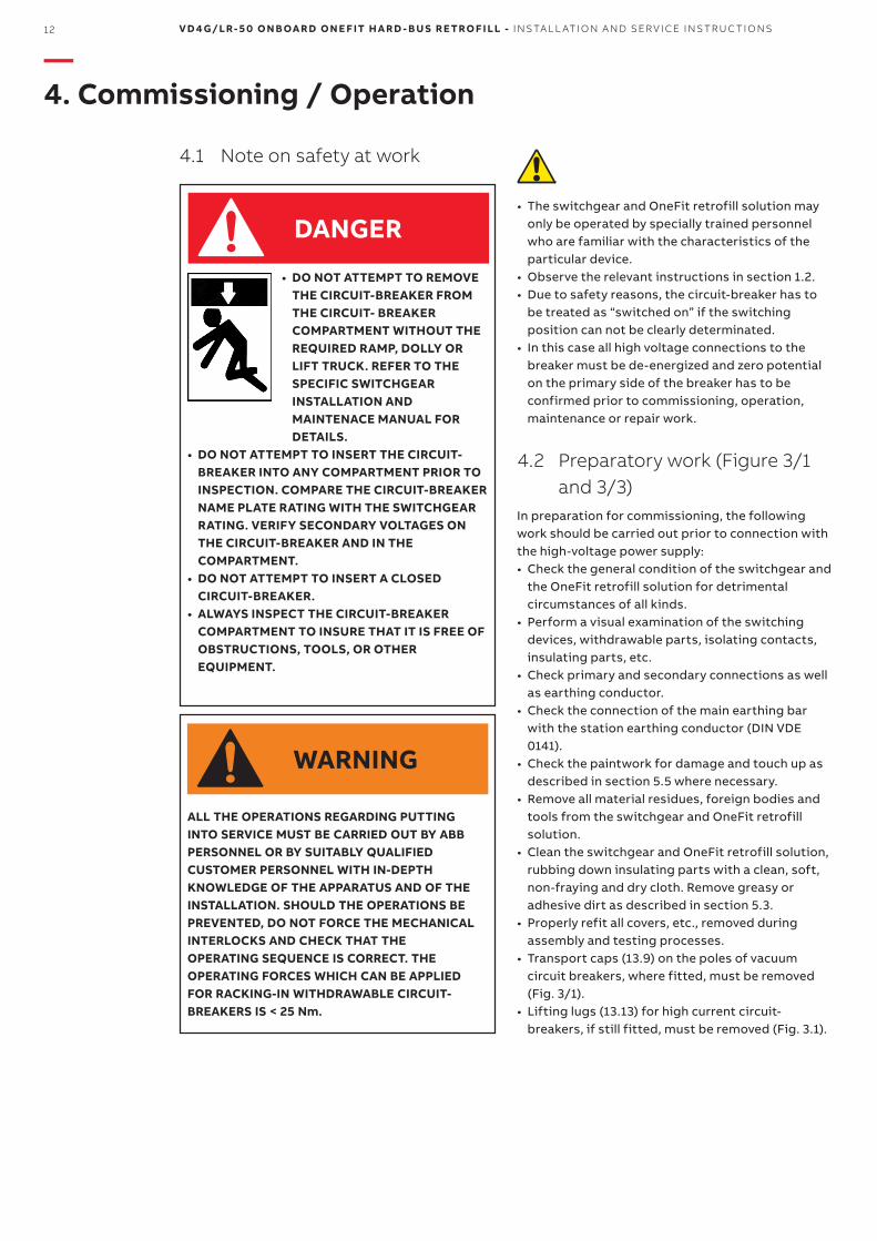
• DO NOT ATTEMPT TO REMOVE THE CIRCUIT-BREAKER FROM THE CIRCUIT- BREAKER COMPARTMENT WITHOUT THE REQUIRED RAMP, DOLLY OR LIFT TRUCK. REFER TO THE SPECIFIC SWITCHGEAR INSTALLATION AND MAINTENACE MANUAL FOR DETAILS.
• DO NOT ATTEMPT TO INSERT THE CIRCUIT-BREAKER INTO ANY COMPARTMENT PRIOR TO INSPECTION. COMPARE THE CIRCUIT-BREAKER NAME PLATE RATING WITH THE SWITCHGEAR RATING. VERIFY SECONDARY VOLTAGES ON THE CIRCUIT-BREAKER AND IN THE COMPARTMENT.
• DO NOT ATTEMPT TO INSERT A CLOSED CIRCUIT-BREAKER.
• ALWAYS INSPECT THE CIRCUIT-BREAKER COMPARTMENT TO INSURE THAT IT IS FREE OF OBSTRUCTIONS, TOOLS, OR OTHER EQUIPMENT.
ALL THE OPERATIONS REGARDING PUTTING INTO SERVICE MUST BE CARRIED OUT BY ABB PERSONNEL OR BY SUITABLY QUALIFIED CUSTOMER PERSONNEL WITH IN-DEPTH KNOWLEDGE OF THE APPARATUS AND OF THE INSTALLATION. SHOULD THE OPERATIONS BE PREVENTED, DO NOT FORCE THE MECHANICAL INTERLOCKS AND CHECK THAT THE OPERATING SEQUENCE IS CORRECT. THE OPERATING FORCES WHICH CAN BE APPLIED FOR RACKING-IN WITHDRAWABLE CIRCUIT-BREAKERS IS < 25 Nm.
4.1 Note on safety at work
DANGER
WARNING
M ED I U M VO LTAG E S ER V I CE 13
• Perform AC voltage testing on the main circuits to IEC 62271-200 as far as necessary. Pay special attention during this pro cedure to voltage transformers and cables etc.
• Turn the auxiliary and control voltage on.• Check the function of the charging motor.• Carry out test operations of switching devices
manually or by electrical control, and simul-taneously observe the relevant position indicators.
• Manual charging of the stored-energy spring system (see chapter 4.5.1).
• Carry out test operations of switching devices manually or by electrical control, and simul-taneously observe the relevant position indicators.
• The instruction manual has to be stored accessible to the operating personnel at any time.
• Check mechanical and electrical interlocks for effectiveness, without using force.
• Set the protective devices in the panel to the required values, and check their functioning with test equipment.
• On motor-driven withdrawable trucks, check the direction of rotation of the travel motors as described in section 5.6.5.
• For any further questions on the functions of the withdrawable circuit-breaker part and its testing, see section section 5.6.
• Instruct the local operators in the fundamental details of regular handling of the switchgear and OneFit retrofill solution.
• Check on the operational readiness and switching status of upstream and downstream electrical installations.
• From areas bordering on the switchgear, in accordance with responsibilities, check on the following where applicable: - Power cables - Auxiliary cables - Supply voltage source - Remote control - Entire earthing installation, according to DIN
VDE 0141 - Switchroom equipment - Switchroom condition
4.3 Start-up
• Comply with all relevant safety regulations.• Ensure that the circuit-breakers and switch
disconnectors in the switchgear are in the OFF position.
• Remove any existing earthing and short-circuiting connections in the critical switching area.
• Energize the feed cables.• Connect the switchgear, step-by-step, observing
the signals and indicators.• Check that the relevant conductors are in phase,
as far as necessary when several incoming feeder cables and switchgear sections are concerned.
• Carry out all measurements and check all functions dependent on the high voltage power supply being connected.
• Watch out for irregularities of any kind.
14 V D 4 G/LR- 5 0 O N B OA R D O N E F IT H A R D - B U S R E TRO F I LL - I NS TA L L ATI O N A N D SER V I CE I NS TR U C TI O NS
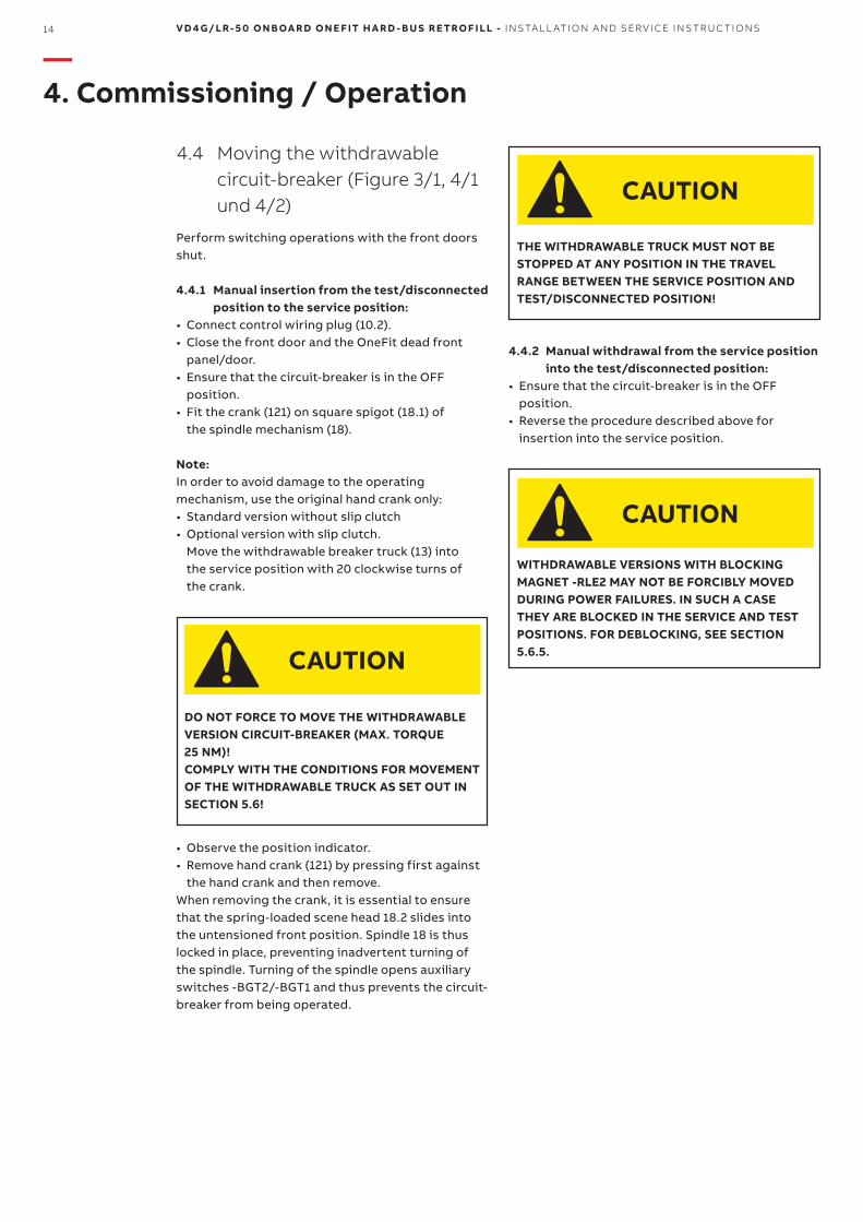
DO NOT FORCE TO MOVE THE WITHDRAWABLE VERSION CIRCUIT-BREAKER (MAX. TORQUE 25 NM)!COMPLY WITH THE CONDITIONS FOR MOVEMENT OF THE WITHDRAWABLE TRUCK AS SET OUT IN SECTION 5.6!
THE WITHDRAWABLE TRUCK MUST NOT BE STOPPED AT ANY POSITION IN THE TRAVEL RANGE BETWEEN THE SERVICE POSITION AND TEST/DISCONNECTED POSITION!
WITHDRAWABLE VERSIONS WITH BLOCKING MAGNET -RLE2 MAY NOT BE FORCIBLY MOVED DURING POWER FAILURES. IN SUCH A CASE THEY ARE BLOCKED IN THE SERVICE AND TEST POSITIONS. FOR DEBLOCKING, SEE SECTION 5.6.5.
Note:In order to avoid damage to the operating mechanism, use the original hand crank only:• Standard version without slip clutch• Optional version with slip clutch.
Move the withdrawable breaker truck (13) into the service position with 20 clockwise turns of the crank.
4.4.2 Manual withdrawal from the service position into the test/disconnected position:
• Ensure that the circuit-breaker is in the OFF position.
• Reverse the procedure described above for insertion into the service position.
• Observe the position indicator.• Remove hand crank (121) by pressing first against
the hand crank and then remove. When removing the crank, it is essential to ensure that the spring-loaded scene head 18.2 slides into the untensioned front position. Spindle 18 is thus locked in place, preventing inadvertent turning of the spindle. Turning of the spindle opens auxiliary switches -BGT2/-BGT1 and thus prevents the circuit-breaker from being operated.
4.4 Moving the withdrawable circuit-breaker (Figure 3/1, 4/1 und 4/2)
Perform switching operations with the front doors shut.
4.4.1 Manual insertion from the test/disconnected position to the service position:
• Connect control wiring plug (10.2).• Close the front door and the OneFit dead front
panel/door.• Ensure that the circuit-breaker is in the OFF
position.• Fit the crank (121) on square spigot (18.1) of
the spindle mechanism (18).
—4. Commissioning / Operation
CAUTIONCAUTION
CAUTION
CAUTION
13.2 1013.3 128
13.5 13.4 13.8 13.1118/18.1
M ED I U M VO LTAG E S ER V I CE 15
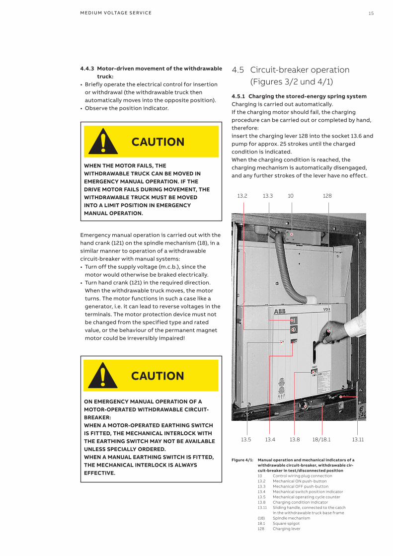
4.5 Circuit-breaker operation (Figures 3/2 und 4/1)
4.5.1 Charging the stored-energy spring systemCharging is carried out automatically. If the charging motor should fail, the charging procedure can be carried out or completed by hand, therefore:insert the charging lever 128 into the socket 13.6 and pump for approx. 25 strokes until the charged condition is indicated. When the charging condition is reached, the charging mechanism is auto matically disengaged, and any further strokes of the lever have no effect.
Figure 4/1: Manual operation and mechanical indicators of a withdrawable circuit-breaker, withdrawable cir-cuit-breaker in test/disconnected position
10 Control wiring plug connection 13.2 Mechanical ON push-button 13.3 Mechanical OFF push-button 13.4 Mechanical switch position indicator 13.5 Mechanical operating cycle counter 13.8 Charging condition indicator 13.11 Sliding handle, connected to the catch
in the withdrawable truck base frame (18) Spindle mechanism 18.1 Square spigot 128 Charging lever
Emergency manual operation is carried out with the hand crank (121) on the spindle mechanism (18), in a similar manner to operation of a withdrawable circuit-breaker with manual systems:• Turn off the supply voltage (m.c.b.), since the
motor would otherwise be braked electrically.• Turn hand crank (121) in the required direction.
When the withdrawable truck moves, the motor turns. The motor functions in such a case like a generator, i.e. it can lead to reverse voltages in the terminals. The motor protection device must not be changed from the specified type and rated value, or the behaviour of the permanent magnet motor could be irreversibly impaired!
WHEN THE MOTOR FAILS, THE WITHDRAWABLE TRUCK CAN BE MOVED IN EMERGENCY MANUAL OPERATION. IF THE DRIVE MOTOR FAILS DURING MOVEMENT, THE WITHDRAWABLE TRUCK MUST BE MOVED INTO A LIMIT POSITION IN EMERGENCY MANUAL OPERATION.
ON EMERGENCY MANUAL OPERATION OF A MOTOR-OPERATED WITHDRAWABLE CIRCUIT-BREAKER:WHEN A MOTOR-OPERATED EARTHING SWITCH IS FITTED, THE MECHANICAL INTERLOCK WITH THE EARTHING SWITCH MAY NOT BE AVAILABLE UNLESS SPECIALLY ORDERED.WHEN A MANUAL EARTHING SWITCH IS FITTED, THE MECHANICAL INTERLOCK IS ALWAYS EFFECTIVE.
4.4.3 Motor-driven movement of the withdrawable truck:
• Briefly operate the electrical control for insertion or withdrawal (the withdrawable truck then automatically moves into the opposite position).
• Observe the position indicator.
CAUTION
CAUTION
18 12113
16 V D 4 G/LR- 5 0 O N B OA R D O N E F IT H A R D - B U S R E TRO F I LL - I NS TA L L ATI O N A N D SER V I CE I NS TR U C TI O NS
RELEASE OF RUN-ON BLOCK MAY ONLY BE PERFORMED BY SERVICING PERSONNEL FROM ABB OR ADEQUATELY TRAINED SPECIALIST STUFF.
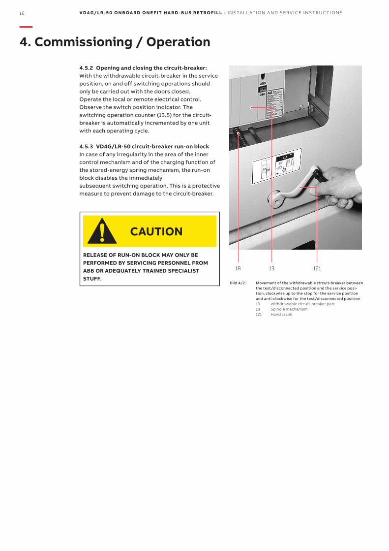
4.5.2 Opening and closing the circuit-breaker:With the withdrawable circuit-breaker in the service position, on and off switching operations should only be carried out with the doors closed.Operate the local or remote electrical control.Observe the switch position indicator. The switching operation counter (13.5) for the circuit-breaker is automatically incremented by one unit with each operating cycle.
4.5.3 VD4G/LR-50 circuit-breaker run-on block In case of any irregularity in the area of the inner control mechanism and of the charging function of the stored-energy spring mechanism, the run-on block disables the immediately subsequent switching operation. This is a protective measure to prevent damage to the circuit-breaker.
Bild 4/2: Movement of the withdrawable circuit-breaker between the test/disconnected position and the service posi-tion, clockwise up to the stop for the service position and anti-clockwise for the test/disconnected position
13 Withdrawable circuit-breaker part 18 Spindle mechanism 121 Hand crank
CAUTION
—4. Commissioning / Operation
M ED I U M VO LTAG E S ER V I CE 17
Maintenance serves to preserve trouble-free operation and achieve the longest possible working life of the switchgear. In accordance with DIN 31051, IEC 61208 and IEC 62271-1, it comprises the following closely related activities:Inspection: Determination of the actual condition.Servicing: Measures to preserve the specified
condition.Repairs: Measures to restore the specified
condition.
5.1 GeneralVacuum circuit-breakers are characterized by their simple and robust construction. They have a long life expectancy. Their operating mechanisms have a low maintenance requirement, and the interrupters are maintenance-free during their working life. There is no adverse effect on the vacuum, even from frequent switching of operating and short-circuit currents.The servicing intervals and scope are determined by environmental influences, the switching sequen ces and number of short-circuit breaking operations.
Note:The following must be observed for all maintenance work:• The relevant specifications in section 1.2.2• Notes on safety at work in section 4.1• Standards and specifications in the country of
installation.
MAINTENANCE WORK MAY ONLY BE PERFORMED BY FULLY TRAINED PERSONNEL, OBSERVING ALL THE RELEVANT SAFETY REGULATIONS. IT IS RECOMMENDED THAT ABB AFTER-SALES SERVICE PERSONNEL SHOULD BE CALLED IN, AT LEAST DURING THE PERFORMANCE OF SERVICING AND REPAIR WORK. WHILE THE WORK IS IN PROGRESS, ALL SUPPLY VOLTAGE SOURCES MUST ALSO BE DISCONNECTED AND SECURED TO PREVENT RECONNECTION.
IN ORDER TO PREVENT ACCIDENTS (PARTICULARLY INJURY TO HANDS!) EXTREME CARE SHOULD BE TAKEN DURING ALL REPAIR WORK ON THE OPERATING MECHANISM, ESPECIALLY WITH FRONT PLATE REMOVED.
THE REPLACEMENT OF PARTS NOT INCLUDED IN THE "LIST OF SPARE PARTS/ACCESSORIES" MUST ONLY BE CARRIED OUT BY ABB PERSONNEL. IN PARTICULAR:
• COMPLETE POLE WITH BUSHINGS/CONNECTIONS
• ACTUATOR• TRANSMISSION SYSTEM.
The spiral spring in the spring energy storage mechanism, for instance, retains a basic tension which is independent of the charging and discharging processes during switching, so as to ensure correct function. This spring energy can be inadvertently released if work is performed incorrectly on the spring mechanism!
Additional instructions may be included in the technical documents provided with the switchgear (e.g. also special agreed operating conditions).For maintenance instructions read also the relevant chapters of 1VCD601413.Together with this instruction manual, it is essential to consult manual 1VCD601413, Vacuum circuit-breaker type VD4G-50.The service life data fundamentally apply to all components which are not directly influenced by the operator.Components operated manually (movement of the withdrawable truck, etc.) may deviate, depending on how they are handled.If necessary, further details can be taken from the technical documentation for the switchgear (including, for example, any agreed special operating conditions).
—5 Maintenance
CAUTION
WARNING
DANGER
18 V D 4 G/LR- 5 0 O N B OA R D O N E F IT H A R D - B U S R E TRO F I LL - I NS TA L L ATI O N A N D SER V I CE I NS TR U C TI O NS
5.2 Service life
Typical life expectancies for von VD4G/LR-50 Generator circuit-breakers:• The maintenance-free vacuum interrupters up to
10,000 operating cycles (see 1VCD601413)• The breaker itself, depending on presupposing
carefully performed inspection and servicing work and normal operating conditions, up to 10,000 operating cycles
The service life data fundamentally apply to all components which are not directly influenced by the operator.Components operated manually (movement of the withdrawable part, etc.) may deviate.
5.3 Inspection and functional testing
5.3.1 General• The proper condition of the switching device is to
be verified by regular inspection, as shown in the Table 1.
• The checks are to be performed in accordance with BGV A3 standards.
• Inspection at fixed intervals may be waived if the switchgear is permanently monitored by a qualified personnel.
• The checks first and foremost comprise visual examination for contamination, corrosion, moisture and discharge phenomena.
• In unusual operating conditions (including adverse climatic conditions) and/or special environmental pollutions (e.g. heavy contamination and aggressive atmosphere), inspection may also be necessary at shorter intervals.
• Visual checking of the isolating contact system. We recommend to turn alternately the contact system in order to clean the inner contact points of the contact system.
• The contact points should be cleaned if signs of unperminable overheating (discoloured surface) are visible (see section Repairs).
• If irregular conditions are detected, then corresponding repair measures should be initiated. For details of inspection and functional testing, see the relevant sections of manual 1VCD601413
MAXIMUM TORQUE 25 Nm!
5.3.2 Withdrawable assemblyThe inspection should always include a visual examination of the withdrawable part assembly. Special attention is to be paid to those parts which may possibly be damaged by improper handling. (See section “Inspection/Circuit-breaker in general“).• Visual checking of the isolating contact system.
We recommend turning the contact system alternately in order to clean the inner contact points. The contact points should be cleaned if signs of impermissible overheating (discoloured surface) are visible (see section “Repairs“).
• The interlock conditions and the ease of movement of the lock and release device are to be checked as described under “Repairs”. When checking the interlock conditions, it is essential to ensure that no force is used.
—5 Maintenance
WARNING
M ED I U M VO LTAG E S ER V I CE 19
USE ONLY CLEANING AGENTS FREE OF HALOGEN, IN NO CASE 111-TRICHLORATAN, TRICHLOROETHYLENE OR TETRACHLOROMETHANE!
5.4 Servicing
Cleaning surfaces:If, on the occasion of an inspection in accordance with (5.2), the necessity of cleaning measures has been established, proceed as follows:• Before cleaning, where required, the working area
must be switched off and secured against reconnection in accordance with the „Safety Regulations“ specified by DIN VDE/IEC.
• Cleaning the surfaces in general: - Poorly adhering dry dust residues with a soft dry
cloth. - More strongly adhering grime with mildly alka-
line household cleaner or with Isopropanol.• Cleaning insulating surfaces and conductive
components: - Minor grime with Isopropanol.
• After cleaning, rinse with clean water and dry carefully.
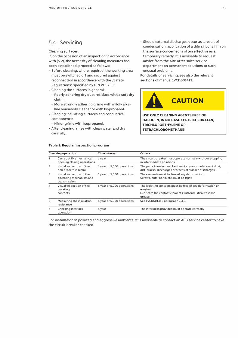
Checking operation Time interval Critera
1 Carry out five mechanical opening closing operations
1 year The circuit-breaker must operate normally without stopping in intermediate positions
2 Visual inspection of the poles (parts in resin)
1 year or 5,000 operations The parts in resin must be free of any accumulation of dust, dirt, cracks, discharges or traces of surface discharges
3 Visual inspection of the operating mechanism and transmission
1 year or 5,000 operations The elements must be free of any deformationScrews, nuts, bolts, etc. must be tight
4 Visual inspection of the isolating contacts
5 year or 5,000 operations The isolating contacts must be free of any deformation or erosionLubricate the contact elements with industrial vaseline grease
5 Measuring the insulation resistance
5 year or 5,000 operations See 1VCD601413 paragraph 7.3.3.
6 Checking interlock operation
5 year The interlocks provided must operate correctly
Table 1: Regular inspection program
For installation in polluted and aggressive ambients, it is advisable to contact an ABB service center to have the circuit-breaker checked.
CAUTION
• Should external discharges occur as a result of condensation, application of a thin silicone film on the surface concerned is often effective as a temporary remedy. It is advisable to request advice from the ABB after-sales service department on permanent solutions to such unusual problems.
For details of servicing, see also the relevant sections of manual 1VCD601413.
20 V D 4 G/LR- 5 0 O N B OA R D O N E F IT H A R D - B U S R E TRO F I LL - I NS TA L L ATI O N A N D SER V I CE I NS TR U C TI O NS
—5 Maintenance
THE SET INSTALLATION POSITION OF CONTACT ARMS MUST NOT BE CHANGED BY THE IMPROPER USE OF FORCE.
5.5 Repairs
5.5.1 Repair of surface damageRepair of surface damage:• Sheet steel parts, painted:
- Remove rust, e.g. with a wire brush. - Grind off paint coat and degrease. - Apply anti-rust primer and top coat.
• Use top coat paint in the standard colour RAL 7035.Sheet steel parts, with zinc surface and passivated functional parts:
- Remove white rust with a wire brush or cleaning pad (e.g. Scotch-Brite white).
- Remove loosely adhering particles with a dry cloth.
- Apply zinc spray or zinc dust primer.• Functional parts, phosphated:
- Remove rust with a wire brush or cleaning pad (e.g. Scotch-Brite white).
- Clean with a dry cloth. - Grease with Isoflex Topas NB 52.
• Switchgear and OneFit retrofill solution in general: - Observe the maintenance instructions in the
manuals for the individual equipment compo-nents.
- Check that the bolt connections at the contact points in the busbar system and the earth con-nections are tight, and that the isolating contact system functions correctly.
- Regrease the contact points and mechanism of the withdrawable part insertion system as necessary, or, when lubrication is inadequate or missing, thoroughly clean the areas concerned and regrease with Isoflex Topas NB 52 lubricant.
- Where required, regrease or thoroughly clean slide plates and bearings in the panel and regrease them with Isoflex Topas NB 52 lubricant. Remove the contact system for thoroughly clean-ing as described below (Figure 5/1):
- Slide the two inner annular tension springs (4.4) facing the breaker pole to a position beside the other two outer annual tension springs, thus re-leasing contact system (4.3), and remove the contact system from contact arm.
- Fit a new contact system back to front on the thin end of arbor (127), and slide it forwards onto the thicker part of the shank.
- Fit arbor (127) onto the relevant contact arm, slide the contact system (4.3) over onto the contact arm, and withdraw the arbor.
- Check all contact fingers and annular tension springs for perfect fit.
5.5.2 Replacement of withdrawable assembly (Figures 4/2 and 5/1 to 5/5)
• Disconnect plug connector (10.3) only for withdrawable assembly of type B)
• Remove interlock rod (13.91) with pin (13.27) from the withdrawable assembly.
• For motorized withdrawable assemblies, remove the two socket head bolts which are accessible from below the assembly (2 bolts M4).
• Unbolt the circuit-breaker from the withdrawable assembly (4 x M12 bolts).
• Mount the circuit-breaker on a new with drawable assembly in the reverse order, using new circlip and special pliers for pin (13.27). Check the setting of interlocking rod (13.91): - Turn spindlel (18) anti-clockwise to the stop for
the disconnected position: - The distance between lever (13.26) and cam
(13.25) must be 2+1 mm, The distance between roller (13.24) and block-ing bracket (13.92) must be 0.2-0.5 mm.
- Turn spindle (18) clockwise to the stop for the service position: - The distance between lever (13.26) and cam
(13.25) must be 2+1 mm. - The distance between roller (13.24) and block-
ing bracket (13.92) must be 0.2-0.5 mm. - Loosen bolts (13.91.2 or 13.92.1) for any neces-
sary adjustment.For details of repairs, see also the relevant sections of manual 1VCD601413.
DANGER
M ED I U M VO LTAG E S ER V I CE 21
WHEN THE WITHDRAWABLE TRUCK MOVES, THE MOTOR TURNS. THE MOTOR FUNCTIONS IN SUCH A CASE LIKE A GENERATOR, I.E. IT CAN LEAD TO REVERSE VOLTAGES IN THE TERMINALS.
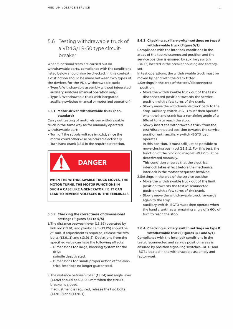
5.6 Testing withdrawable truck of a VD4G/LR-50 type circuit-breaker
When functional tests are carried out on withdrawable parts, compliance with the con ditions listed below should also be checked. In this context, a distinction should be made between two types of the devices for the VD4 withdrawable tuck:• Type A: Withdrawable assembly without integrated
auxiliary switches (manual operation only)• Type B: Withdrawable truck with integrated
auxiliary switches (manual or motorized operation)
5.6.1 Motor-driven withdrawable truck (non-standard)
Carry out testing of motor-driven withdrawable truck in the same way as for manually operated withdrawable part:• Turn off the supply voltage (m.c.b.), since the
motor could otherwise be braked electrically.• Turn hand crank (121) in the required direction.
5.6.3 Checking auxiliary switch settings on type A withdrawable truck (Figure 5/1)
Compliance with the interlock conditions in the areas of the test/disconnected position and the service position is ensured by auxiliary switch -BGT3, located in the breaker housing and factory-set.In test operations, the withdrawable truck must be moved by hand with the crank fitted.1. Settings in the area of the test/disconnected
position - Move the withdrawable truck out of the test/disconnected position towards the service position with a few turns of the crank.
- Slowly move the withdrawable truck back to the stop. Auxiliary switch -BGT3 must then operate when the hand crank has a remaining angle of ≥ 60o of turn to reach the stop.
- Slowly insert the withdrawable truck from the test/disconnected position towards the service position until auxiliary switch -BGT3 just operates. In this position, it must still just be possible to move closing push rod (13.2.1). For this test, the function of the blocking magnet -RLE2 must be deactivated manually. This condition ensures that the electrical interlock takes effect before the mechanical interlock in the motion sequence involved.
2. Settings in the area of the service position - Move the withdrawable truck out of the limit position towards the test/disconnected position with a few turns of the crank.
- Slowly move the withdrawable truck forwards again to the stop: Auxiliary switch -BGT3 must then operate when the hand crank has a remaining angle of ≥ 60o of turn to reach the stop.
DANGER
5.6.2 Checking the correctness of dimensional settings (Figures 5/1 to 5/5)
1. The distance between lever (13.26) operated by link rod (13.91) and plastic cam (13.25) should be 2+1 mm. If adjustment is required, release the two bolts (13.91.1) and (13.91.2). Deviations from the specified value can have the following effects: - Dimensions too large, blocking system for the
drive spindle deactivated.
- Dimensions too small, proper action of the elec-trical interlock no longer guaranteed.
2. The distance between roller (13.24) and angle lever (13.92) should be 0.2-0.5 mm when the circuit-breaker is closed.
If adjustment is required, release the two bolts (13.91.2) and (13.91.1).
5.6.4 Checking auxiliary switch settings on type B withdrawable truck (Figures 3/3 and 5/1)
Compliance with the interlock conditions in the test/disconnected and service position areas is ensured by position signalling switches -BGT2 and -BGT1 located in the withdrawable assembly and factory-set.
22 V D 4 G/LR- 5 0 O N B OA R D O N E F IT H A R D - B U S R E TRO F I LL - I NS TA L L ATI O N A N D SER V I CE I NS TR U C TI O NS
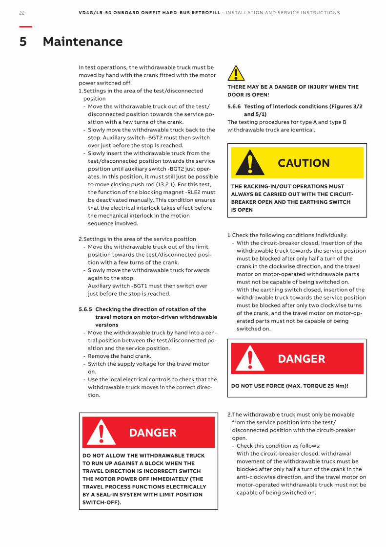
DO NOT USE FORCE (MAX. TORQUE 25 Nm)!
1. Check the following conditions individually: - With the circuit-breaker closed, insertion of the
withdrawable truck towards the service position must be blocked after only half a turn of the crank in the clockwise direction, and the travel motor on motor-operated withdrawable parts must not be capable of being switched on.
- With the earthing switch closed, insertion of the withdrawable truck towards the service position must be blocked after only two clockwise turns of the crank, and the travel motor on motor-op-erated parts must not be capable of being switched on.
—5 Maintenance
DANGER
DO NOT ALLOW THE WITHDRAWABLE TRUCK TO RUN UP AGAINST A BLOCK WHEN THE TRAVEL DIRECTION IS INCORRECT! SWITCH THE MOTOR POWER OFF IMMEDIATELY (THE TRAVEL PROCESS FUNCTIONS ELECTRICALLY BY A SEAL-IN SYSTEM WITH LIMIT POSITION SWITCH-OFF).
THE RACKING-IN/OUT OPERATIONS MUST ALWAYS BE CARRIED OUT WITH THE CIRCUIT-BREAKER OPEN AND THE EARTHING SWITCH IS OPEN
THERE MAY BE A DANGER OF INJURY WHEN THE DOOR IS OPEN!
5.6.6 Testing of interlock conditions (Figures 3/2 and 5/1)
The testing procedures for type A and type B withdrawable truck are identical.
CAUTION
DANGER
In test operations, the withdrawable truck must be moved by hand with the crank fitted with the motor power switched off.1. Settings in the area of the test/disconnected
position - Move the withdrawable truck out of the test/disconnected position towards the service po-sition with a few turns of the crank.
- Slowly move the withdrawable truck back to the stop. Auxiliary switch -BGT2 must then switch over just before the stop is reached.
- Slowly insert the withdrawable truck from the test/disconnected position towards the service position until auxiliary switch -BGT2 just oper-ates. In this position, it must still just be possible to move closing push rod (13.2.1). For this test, the function of the blocking magnet -RLE2 must be deactivated manually. This condition ensures that the electrical interlock takes effect before the mechanical interlock in the motion sequence involved.
2. Settings in the area of the service position - Move the withdrawable truck out of the limit position towards the test/disconnected posi-tion with a few turns of the crank.
- Slowly move the withdrawable truck forwards again to the stop: Auxiliary switch -BGT1 must then switch over just before the stop is reached.
5.6.5 Checking the direction of rotation of the travel motors on motor-driven withdrawable versions
- Move the withdrawable truck by hand into a cen-tral position between the test/disconnected po-sition and the service position.
- Remove the hand crank. - Switch the supply voltage for the travel motor
on. - Use the local electrical controls to check that the
withdrawable truck moves in the correct direc-tion.
2. The withdrawable truck must only be movable from the service position into the test/disconnected position with the circuit-breaker open. - Check this condition as follows:
With the circuit-breaker closed, withdrawal movement of the withdrawable truck must be blocked after only half a turn of the crank in the anti-clockwise direction, and the travel motor on motor-operated withdrawable truck must not be capable of being switched on.
M ED I U M VO LTAG E S ER V I CE 23
3. Closing of the circuit-breaker must only be possible when the withdrawable truck is in the defined test/disconnected position or service position. The control wiring plug (10.2) must previously have been inserted. Check this condition as follows: - It must not be possible to close the cir-
cuit-breaker with the withdrawable truck in any position between the test/disconnected posi-tion and the service position.
- Enabling of switching when the withdrawable truck moves into the service position is effected electrically by operation of auxiliary switch -BGT3 in the breaker housing (for type A), or of auxiliary switch -BGT1 in the withdrawable as-sembly (for type B), and mechanically slightly earlier; the latter corresponds to a position ap-proximately half a turn of the crank before stop.
- For motion into the test/disconnected position, the same enabling conditions apply analogously, in this case by means of auxiliary switch -BGT3 in the breaker housing (for type A) or the auxiliary switch -BGT2 in the withdrawable assembly (for type B).
4. It must only be possible to open the circuit-breaker (manually) when the withdrawable truck is in the service position or test/disconnected position and the control voltage has failed. Check this condition.
5. Withdrawable truck with order-related blocking magnet -RLE2 may not be moved in case of control power failure, or when there is no control power. Do not forcibly move blocked withdrawable trucks! The blocking magnet -RLE2 is only present on manually operated withdrawable truck. Releasing the blocking magnet -RLE2: - Remove front plate (13.7). - Disengage blocking magnet -RLE2 by pulling the
magnet armature. - While doing so, turn crank (121) about one half
turn (either direction of rotation is permissible). The blocking magnet is only active in the test po-sition and service position. In intermediate posi-tions it has no effect.
6. Disconnection of the control wiring plug (10.2) as well as later insertion must be blocked in the withdrawable truck’s service position. Check this condition.
When parts are required, the serial number of the relevant withdrawable breaker part or circuit-breaker should always be quoted. Setting instructions are to be requested separately.
5.7 Spare parts, auxiliary materials, lubricants
5.7.1 Spare parts
ALL ASSEMBLY OPERATIONS OF SPARE PARTS/ACCESSORIES MUST BE CARRIED OUT FOLLOWING THE INSTRUCTIONS ENCLOSED WITH THE SPARE PARTS, BY ABB PERSONNEL OR BY SUITABLY QUALIFIED CUSTOMER PERSONNEL WITH IN-DEPTH KNOWLEDGE OF THE APPARATUS (IEC/IEEE 62271-37-013 AND IEC 62271-1) AND ALL THE STANDARDS AIMED AT CARRYING OUT THESE INTERVENTIONS IN SAFE CONDITIONS. SHOULD THE MAINTENANCE BE CARRIED OUT BY THE CUSTOMER’S PERSONNEL, RESPONSIBILITY FOR THE INTERVENTIONS REMAINS WITH THE CUSTOMER.BEFORE CARRYING OUT ANY OPERATION, ALWAYS MAKE SURE THAT THE CIRCUIT-BREAKER IS OPEN, NOT SUPPLIED (MEDIUM VOLTAGE CIRCUIT AND AUXILIARY CIRCUITS) AND WITH THE CAPACITORS DISCHARGED.
WARNING
24 V D 4 G/LR- 5 0 O N B OA R D O N E F IT H A R D - B U S R E TRO F I LL - I NS TA L L ATI O N A N D SER V I CE I NS TR U C TI O NS
—5 Maintenance
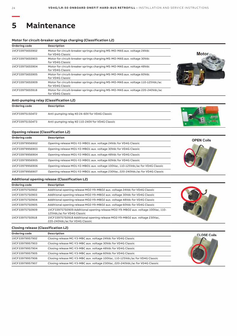
Motor for circuit-breaker springs charging (Classification L2)
Ordering code Description
1VCF339756S5902 Motor for circuit-breaker springs charging MS-MO-MAS aux. voltage 24Vdc for VD4G Classic
1VCF339756S5903 Motor for circuit-breaker springs charging MS-MO-MAS aux. voltage 30Vdc for VD4G Classic
1VCF339756S5904 Motor for circuit-breaker springs charging MS-MO-MAS aux. voltage 48Vdc for VD4G Classic
1VCF339756S5905 Motor for circuit-breaker springs charging MS-MO-MAS aux. voltage 60Vdc for VD4G Classic
1VCF339756S5909 Motor for circuit-breaker springs charging MS-MO-MAS aux. voltage 110-125Vdc/ac for VD4G Classic
1VCF339756S5918 Motor for circuit-breaker springs charging MS-MO-MAS aux. voltage 220-240Vdc/ac for VD4G Classic
Anti-pumping relay (Classification L2)
Ordering code Description
1VCF339751S0472 Anti-pumping relay K0 24-60V for VD4G Classic
1VCF339751S0473 Anti-pumping relay K0 110-240V for VD4G Classic
Opening release (Classification L2)
Ordering code Description
1VCF339799S6902 Opening release MO1-Y2-MBO1 aux. voltage 24Vdc for VD4G Classic
1VCF339799S6903 Opening release MO1-Y2-MBO1 aux. voltage 30Vdc for VD4G Classic
1VCF339799S6904 Opening release MO1-Y2-MBO1 aux. voltage 48Vdc for VD4G Classic
1VCF339799S6905 Opening release MO1-Y2-MBO1 aux. voltage 60Vdc for VD4G Classic
1VCF339799S6906 Opening release MO1-Y2-MBO1 aux. voltage 100Vac, 110-125Vdc/ac for VD4G Classic
1VCF339799S6907 Opening release MO1-Y2-MBO1 aux. voltage 230Vac, 220-240Vdc/ac for VD4G Classic
Additional opening release (Classification L2)
Ordering code Description
1VCF339757S0902 Additional opening release MO2-Y9-MBO2 aux. voltage 24Vdc for VD4G Classic
1VCF339757S0903 Additional opening release MO2-Y9-MBO2 aux. voltage 30Vdc for VD4G Classic
1VCF339757S0904 Additional opening release MO2-Y9-MBO2 aux. voltage 48Vdc for VD4G Classic
1VCF339757S0905 Additional opening release MO2-Y9-MBO2 aux. voltage 60Vdc for VD4G Classic
1VCF339757S0909 1VCF339757S0909 Additional opening release MO2-Y9-MBO2 aux. voltage 100Vac, 110-125Vdc/ac for VD4G Classic
1VCF339757S0918 1VCF339757S0918 Additional opening release MO2-Y9-MBO2 aux. voltage 230Vac, 220-240Vdc/ac for VD4G Classic
Closing release (Classification L2)
Ordering code Description
1VCF339799S7902 Closing release MC-Y3-MBC aux. voltage 24Vdc for VD4G Classic
1VCF339799S7903 Closing release MC-Y3-MBC aux. voltage 30Vdc for VD4G Classic
1VCF339799S7904 Closing release MC-Y3-MBC aux. voltage 48Vdc for VD4G Classic
1VCF339799S7905 Closing release MC-Y3-MBC aux. voltage 60Vdc for VD4G Classic
1VCF339799S7906 Closing release MC-Y3-MBC aux. voltage 100Vac, 110-125Vdc/ac for VD4G Classic
1VCF339799S7907 Closing release MC-Y3-MBC aux. voltage 230Vac, 220-240Vdc/ac for VD4G Classic
M ED I U M VO LTAG E S ER V I CE 25
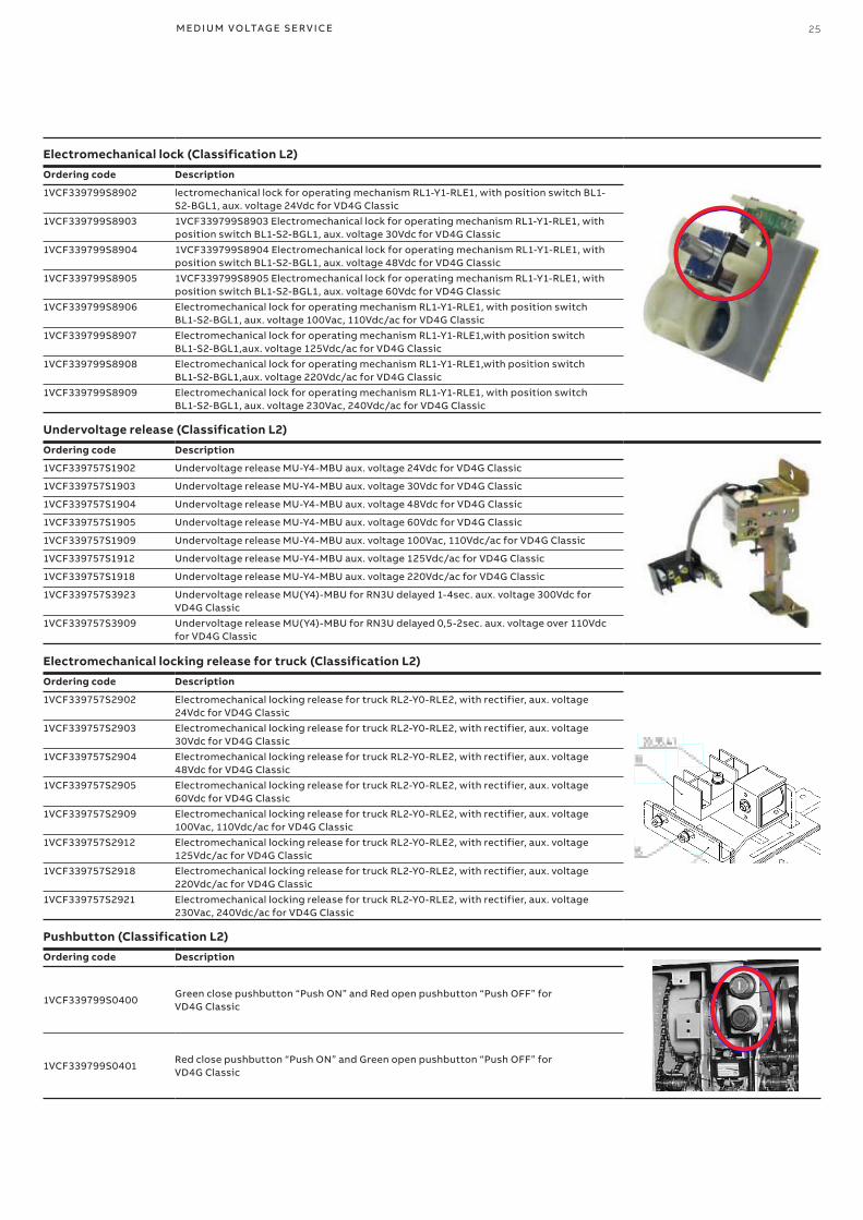
Electromechanical lock (Classification L2)
Ordering code Description
1VCF339799S8902 lectromechanical lock for operating mechanism RL1-Y1-RLE1, with position switch BL1-S2-BGL1, aux. voltage 24Vdc for VD4G Classic
1VCF339799S8903 1VCF339799S8903 Electromechanical lock for operating mechanism RL1-Y1-RLE1, with position switch BL1-S2-BGL1, aux. voltage 30Vdc for VD4G Classic
1VCF339799S8904 1VCF339799S8904 Electromechanical lock for operating mechanism RL1-Y1-RLE1, with position switch BL1-S2-BGL1, aux. voltage 48Vdc for VD4G Classic
1VCF339799S8905 1VCF339799S8905 Electromechanical lock for operating mechanism RL1-Y1-RLE1, with position switch BL1-S2-BGL1, aux. voltage 60Vdc for VD4G Classic
1VCF339799S8906 Electromechanical lock for operating mechanism RL1-Y1-RLE1, with position switch BL1-S2-BGL1, aux. voltage 100Vac, 110Vdc/ac for VD4G Classic
1VCF339799S8907 Electromechanical lock for operating mechanism RL1-Y1-RLE1,with position switch BL1-S2-BGL1,aux. voltage 125Vdc/ac for VD4G Classic
1VCF339799S8908 Electromechanical lock for operating mechanism RL1-Y1-RLE1,with position switch BL1-S2-BGL1,aux. voltage 220Vdc/ac for VD4G Classic
1VCF339799S8909 Electromechanical lock for operating mechanism RL1-Y1-RLE1, with position switch BL1-S2-BGL1, aux. voltage 230Vac, 240Vdc/ac for VD4G Classic
Undervoltage release (Classification L2)
Ordering code Description
1VCF339757S1902 Undervoltage release MU-Y4-MBU aux. voltage 24Vdc for VD4G Classic
1VCF339757S1903 Undervoltage release MU-Y4-MBU aux. voltage 30Vdc for VD4G Classic
1VCF339757S1904 Undervoltage release MU-Y4-MBU aux. voltage 48Vdc for VD4G Classic
1VCF339757S1905 Undervoltage release MU-Y4-MBU aux. voltage 60Vdc for VD4G Classic
1VCF339757S1909 Undervoltage release MU-Y4-MBU aux. voltage 100Vac, 110Vdc/ac for VD4G Classic
1VCF339757S1912 Undervoltage release MU-Y4-MBU aux. voltage 125Vdc/ac for VD4G Classic
1VCF339757S1918 Undervoltage release MU-Y4-MBU aux. voltage 220Vdc/ac for VD4G Classic
1VCF339757S3923 Undervoltage release MU(Y4)-MBU for RN3U delayed 1-4sec. aux. voltage 300Vdc for VD4G Classic
1VCF339757S3909 Undervoltage release MU(Y4)-MBU for RN3U delayed 0,5-2sec. aux. voltage over 110Vdc for VD4G Classic
Electromechanical locking release for truck (Classification L2)
Ordering code Description
1VCF339757S2902 Electromechanical locking release for truck RL2-Y0-RLE2, with rectifier, aux. voltage 24Vdc for VD4G Classic
1VCF339757S2903 Electromechanical locking release for truck RL2-Y0-RLE2, with rectifier, aux. voltage 30Vdc for VD4G Classic
1VCF339757S2904 Electromechanical locking release for truck RL2-Y0-RLE2, with rectifier, aux. voltage 48Vdc for VD4G Classic
1VCF339757S2905 Electromechanical locking release for truck RL2-Y0-RLE2, with rectifier, aux. voltage 60Vdc for VD4G Classic
1VCF339757S2909 Electromechanical locking release for truck RL2-Y0-RLE2, with rectifier, aux. voltage 100Vac, 110Vdc/ac for VD4G Classic
1VCF339757S2912 Electromechanical locking release for truck RL2-Y0-RLE2, with rectifier, aux. voltage 125Vdc/ac for VD4G Classic
1VCF339757S2918 Electromechanical locking release for truck RL2-Y0-RLE2, with rectifier, aux. voltage 220Vdc/ac for VD4G Classic
1VCF339757S2921 Electromechanical locking release for truck RL2-Y0-RLE2, with rectifier, aux. voltage 230Vac, 240Vdc/ac for VD4G Classic
Pushbutton (Classification L2)
Ordering code Description
1VCF339799S0400Green close pushbutton “Push ON” and Red open pushbutton “Push OFF” forVD4G Classic
1VCF339799S0401Red close pushbutton “Push ON” and Green open pushbutton “Push OFF” forVD4G Classic
26 V D 4 G/LR- 5 0 O N B OA R D O N E F IT H A R D - B U S R E TRO F I LL - I NS TA L L ATI O N A N D SER V I CE I NS TR U C TI O NS
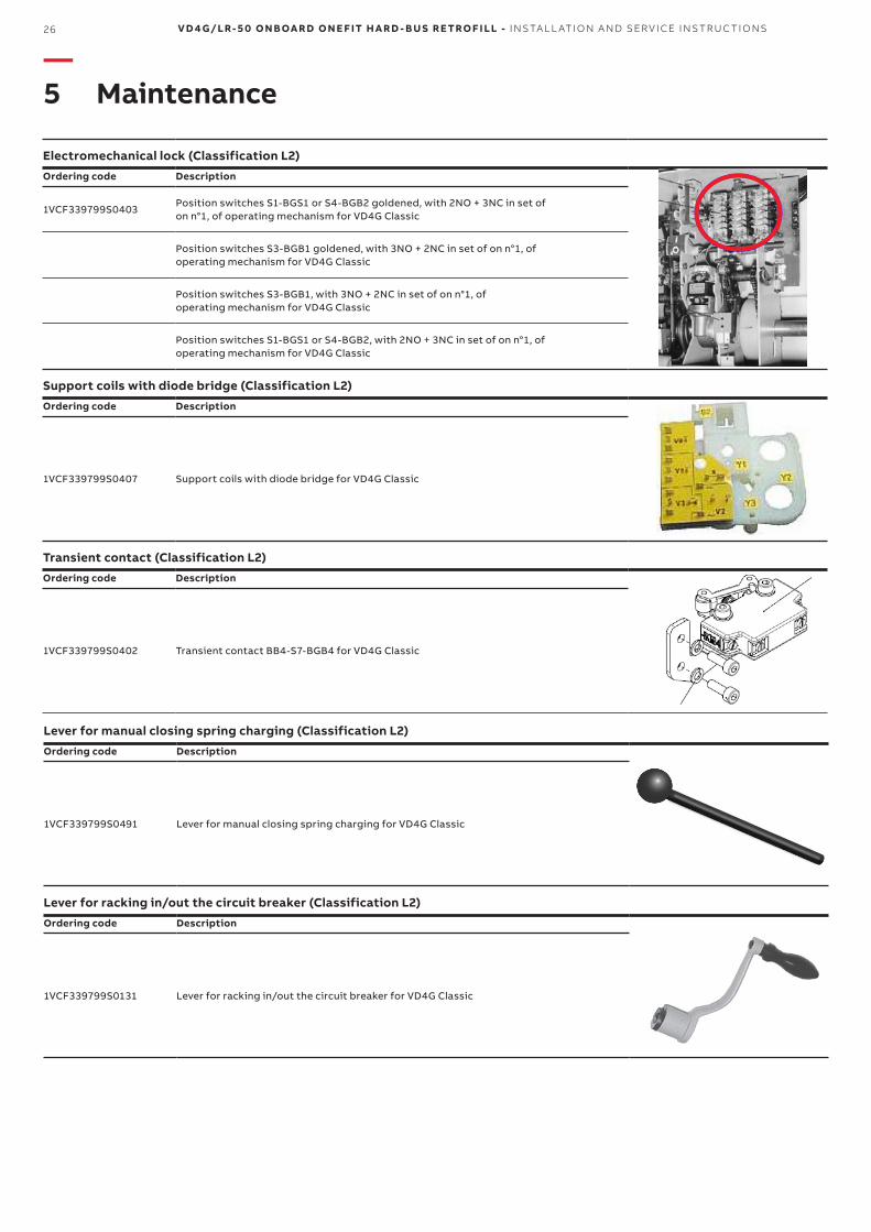
Electromechanical lock (Classification L2)
Ordering code Description
1VCF339799S0403 Position switches S1-BGS1 or S4-BGB2 goldened, with 2NO + 3NC in set ofon n°1, of operating mechanism for VD4G Classic
Position switches S3-BGB1 goldened, with 3NO + 2NC in set of on n°1, ofoperating mechanism for VD4G Classic
Position switches S3-BGB1, with 3NO + 2NC in set of on n°1, ofoperating mechanism for VD4G Classic
Position switches S1-BGS1 or S4-BGB2, with 2NO + 3NC in set of on n°1, ofoperating mechanism for VD4G Classic
Support coils with diode bridge (Classification L2)
Ordering code Description
1VCF339799S0407 Support coils with diode bridge for VD4G Classic
Transient contact (Classification L2)
Ordering code Description
1VCF339799S0402 Transient contact BB4-S7-BGB4 for VD4G Classic
Lever for manual closing spring charging (Classification L2)
Ordering code Description
1VCF339799S0491 Lever for manual closing spring charging for VD4G Classic
Lever for racking in/out the circuit breaker (Classification L2)
Ordering code Description
1VCF339799S0131 Lever for racking in/out the circuit breaker for VD4G Classic
—5 Maintenance
13.26
13.24
13.92
(-BGT3)
13.2.1
121
10.3
13.2.1 -RLE1 13.25 13.26
M ED I U M VO LTAG E S ER V I CE 27
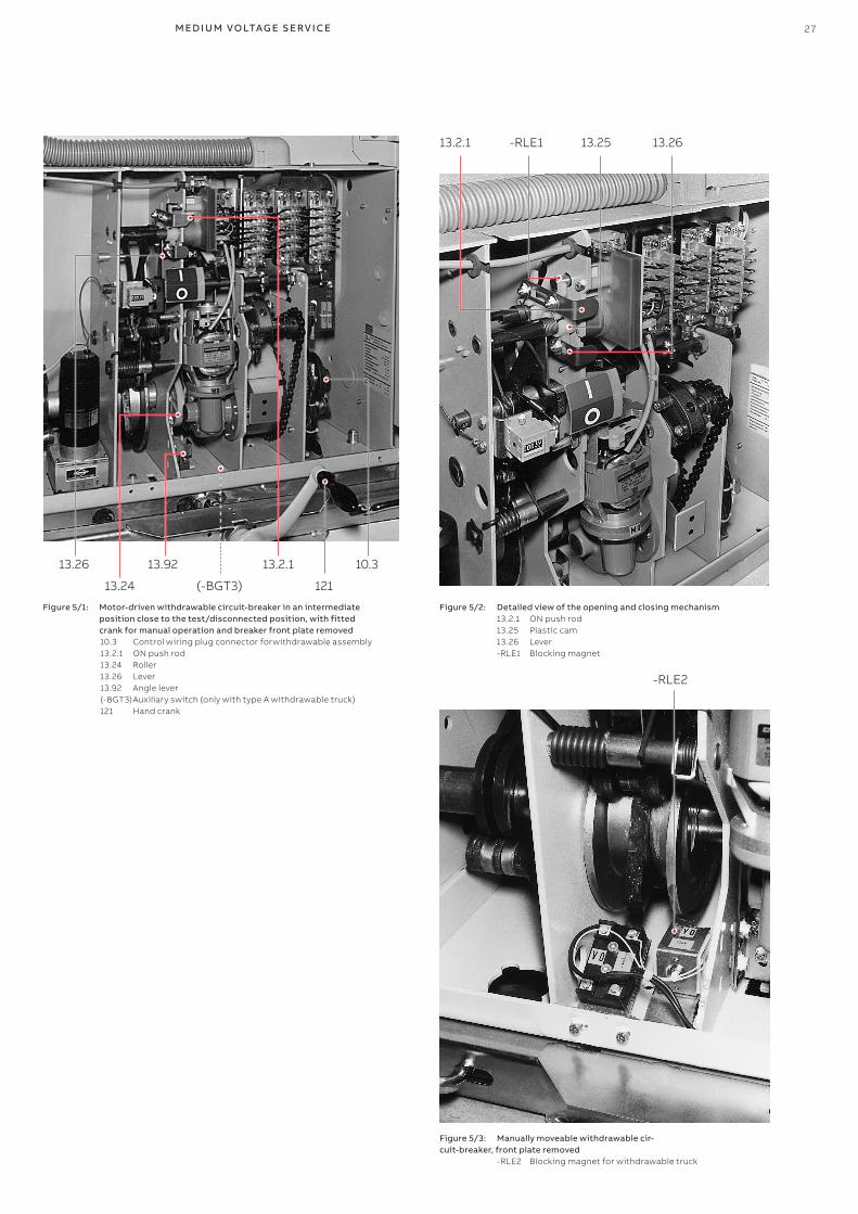
Figure 5/3: Manually moveable withdrawable cir-cuit-breaker, front plate removed -RLE2 Blocking magnet for withdrawable truck
Figure 5/1: Motor-driven withdrawable circuit-breaker in an intermediate position close to the test/disconnected position, with fitted crank for manual operation and breaker front plate removed
10.3 Control wiring plug connector forwithdrawable assembly 13.2.1 ON push rod 13.24 Roller 13.26 Lever 13.92 Angle lever (-BGT3) Auxiliary switch (only with type A withdrawable truck) 121 Hand crank
Figure 5/2: Detailed view of the opening and closing mechanism 13.2.1 ON push rod 13.25 Plastic cam 13.26 Lever -RLE1 Blocking magnet
-RLE2
13.25
13.26
13.24
13.92
13.91
13.91.2
13.27
2+1
13.91.1
13.92.1
0.2-0.5
13.25
13.26
13.24
13.92
13.91
13.91.2
13.27
13.90
13.91.1
2+1
0.2-0.5
13.92.1
28 V D 4 G/LR- 5 0 O N B OA R D O N E F IT H A R D - B U S R E TRO F I LL - I NS TA L L ATI O N A N D SER V I CE I NS TR U C TI O NS
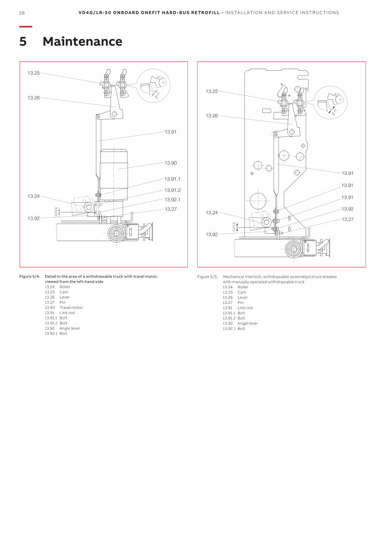
Figure 5/5: Mechanical interlock, withdrawable assembly/circuit-breaker with manually operated withdrawable truck
13.24 Roller 13.25 Cam 13.26 Lever 13.27 Pin 13.91 Link rod 13.91.1 Bolt 13.91.2 Bolt 13.92 Angel lever 13.92.1 Bolt
Figure 5/4: Detail in the area of a withdrawable truck with travel motor, viewed from the left-hand side 13.24 Roller 13.25 Cam 13.26 Lever 13.27 Pin 13.90 Travel motor 13.91 Link rod 13.91.1 Bolt 13.91.2 Bolt 13.92 Angle lever 13.92.1 Bolt
—5 Maintenance
M ED I U M VO LTAG E S ER V I CE 29
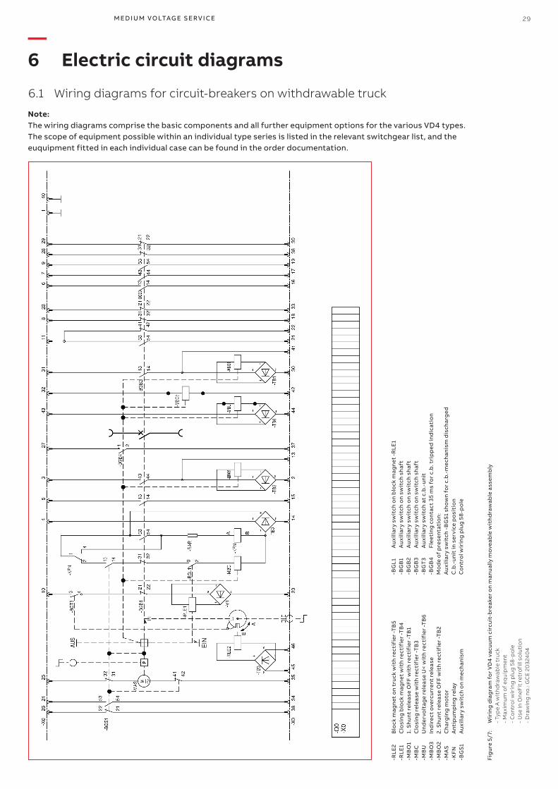
6.1 Wiring diagrams for circuit-breakers on withdrawable truck
Note:The wiring diagrams comprise the basic com ponents and all further equipment options for the various VD4 types.The scope of equipment possible within an individual type series is listed in the relevant switchgear list, and the euquipment fitted in each individual case can be found in the order documentation.
-RLE
2 B
lock
mag
net
on
tru
ck w
ith
rect
ifie
r -T
B5
-RLE
1 C
losi
ng
blo
ck m
agn
et w
ith
rect
ifie
r -T
B4
-MB
O1
1. S
hu
nt r
elea
se O
FF w
ith
rect
ifie
r -T
B1
-MB
C
Clo
sin
g r
elea
se w
ith
rect
ifie
r -T
B3
-MB
U
Un
der
volt
age
rele
ase
U<
wit
h re
ctif
ier
-TB
6-M
BO
3 In
dir
ect
ove
rcu
rren
t re
leas
e-M
BO
2 2.
Sh
unt
rel
ease
OFF
wit
h re
ctif
ier
-TB
2-M
AS
Ch
arg
ing
mo
tor
-KFN
A
ntip
um
pin
g r
elay
-BG
S1
Au
xilia
ry s
wit
ch o
n m
ech
anis
m
-BG
L1
Au
xilia
ry s
wit
ch o
n b
lock
mag
net
-R
LE1
-BG
B1
Au
xilia
ry s
wit
ch o
n sw
itch
sh
aft
-BG
B2
Au
xilia
ry s
wit
ch o
n sw
itch
sh
aft
-BG
B3
Au
xilia
ry s
wit
ch o
n sw
itch
sh
aft
-BG
T3
Au
xilia
ry s
wit
ch a
t c.
b.-
uni
t-B
GB
4 Fl
eeti
ng
co
ntac
t 35
ms
for
c.b
. tri
pp
ed in
dic
atio
nM
od
e o
f p
rese
ntat
ion
:A
uxi
liary
sw
itch
-B
GS
1 sh
ow
n fo
r c.
b.-
mec
han
ism
dis
char
ged
C.b
.-u
nit
in s
ervi
ce p
osi
tio
nC
ont
rol w
irin
g p
lug
58
-po
le
Fig
ure
5/7
: W
irin
g d
iag
ram
fo
r V
D4
vacu
um
cir
cuit
-bre
aker
on
man
ual
ly m
ove
able
wit
hd
raw
able
ass
emb
ly
- Ty
pe
A w
ith
dra
wab
le t
ruck
-
Ma
xim
um
of
equ
ipm
ent
-
Co
ntr
ol w
irin
g p
lug
58
-po
le
- U
se in
On
eFit
ret
rofi
ll so
luti
on
-
Dra
win
g n
o.:
GC
E 2
032
40
4
—6 Electric circuit diagrams
30 V D 4 G/LR- 5 0 O N B OA R D O N E F IT H A R D - B U S R E TRO F I LL - I NS TA L L ATI O N A N D SER V I CE I NS TR U C TI O NS
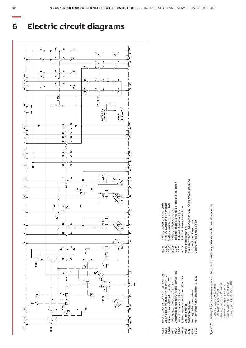
-RLE
2 B
lock
mag
net
on
tru
ck w
ith
rect
ifie
r -T
B5
-RLE
1 C
losi
ng
blo
ck m
agn
et w
ith
rect
ifie
r -T
B4
-MB
O1
1. S
hu
nt r
elea
se O
FF w
ith
rect
ifie
r -T
B1
-MB
C
Clo
sin
g r
elea
se w
ith
rect
ifie
r -T
B3
-MB
U
Un
der
volt
age
rele
ase
U<
wit
h re
ctif
ier
-TB
6-M
BO
3 In
dir
ect
ove
rcu
rren
t re
leas
e-M
BO
2 2.
Sh
unt
rel
ease
OFF
wit
h re
ctif
ier
-TB
2-M
AS
Ch
arg
ing
mo
tor
-KFN
A
ntip
um
pin
g r
elay
-BG
S1
Au
xilia
ry s
wit
ch o
n m
ech
anis
m-B
GL1
A
uxi
liary
sw
itch
on
blo
ck m
agn
et -
RLE
1
-BG
B1
Au
xilia
ry s
wit
ch o
n sw
itch
sh
aft
-BG
B2
Au
xilia
ry s
wit
ch o
n sw
itch
sh
aft
-BG
B3
Au
xilia
ry s
wit
ch o
n sw
itch
sh
aft
-BG
T3
Au
xilia
ry s
wit
ch a
t c.
b.-
uni
t-B
GB
4 Fl
eeti
ng
co
ntac
t 35
ms
for
c.b
. tri
pp
ed in
dic
atio
n-B
GT
2 Li
mit
sw
itch
tes
t p
osi
tio
n-B
GT
1 Li
mit
sw
itch
ser
vice
po
siti
on
Mo
de
of
pre
sent
atio
n:
Au
xilia
ry s
wit
ch -
BG
S1
sho
wn
for
c.b
.-m
ech
anis
m d
isch
arg
edC
.b.-
uni
t in
ser
vice
po
siti
on
Co
ntro
l wir
ing
plu
g 5
8-p
ole
Fig
ure
5/8
: W
irin
g d
iag
ram
fo
r V
D4
vacu
um
cir
cuit
-bre
aker
on
man
ual
ly m
ove
able
wit
hd
raw
able
ass
emb
ly
- Ty
pe
B o
f w
ith
dra
wab
le t
ruck
-
Ma
xim
um
of
equ
ipm
ent
-
Au
xilia
ry s
wit
ch -
BG
B3
wir
ed
- C
on
tro
l wir
ing
plu
g 5
8-p
ole
-
Use
in O
neF
it r
etro
fill
solu
tio
n
- D
raw
ing
no
.: G
CE
2132
701P
010
1
—6 Electric circuit diagrams
M ED I U M VO LTAG E S ER V I CE 31
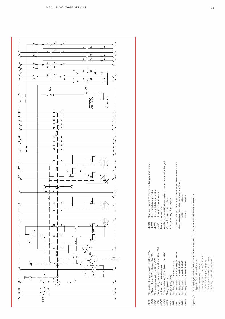
-RLE
1 C
losi
ng
blo
ck m
agn
et w
ith
rect
ifie
r -T
B4
-MB
O1
1. S
hu
nt r
elea
se O
FF w
ith
rect
ifie
r -T
B1
-MB
C
Clo
sin
g r
elea
se w
ith
rect
ifie
r -T
B3
-MB
U
Un
der
volt
age
rele
ase
U<
wit
h re
ctif
ier
-TB
6-M
BO
3 In
dir
ect
ove
rcu
rren
t re
leas
e-M
BO
2 2.
Sh
unt
rel
ease
OFF
wit
h re
ctif
ier
-TB
2-M
AS
Ch
arg
ing
mo
tor
-KFN
A
ntip
um
pin
g r
elay
-BG
S1
Au
xilia
ry s
wit
ch o
n m
ech
anis
m-B
GL1
A
uxi
liary
sw
itch
on
blo
ck m
agn
et -
RLE
1-B
GB
1 A
uxi
liary
sw
itch
on
swit
ch s
haf
t-B
GB
2 A
uxi
liary
sw
itch
on
swit
ch s
haf
t-B
GB
3 A
uxi
liary
sw
itch
on
swit
ch s
haf
t
-BG
B4
Flee
tin
g c
ont
act
35 m
s fo
r c.
b. t
rip
ped
ind
icat
ion
-BG
T2
Lim
it s
wit
ch t
est
po
siti
on
-BG
T1
Lim
it s
wit
ch t
est
po
siti
on
- MAT
M
oto
r d
rive
fo
r d
raw
-out
Mo
de
of
pre
sent
atio
n:
Au
xilia
ry s
wit
ch -
BG
S1
sho
wn
for
c.b
.-m
ech
anis
m d
isch
arg
edC
.b.-
uni
t in
ser
vice
po
siti
on
Co
ntro
l wir
ing
plu
g 5
8-p
ole
*) C
on
nec
tio
n p
oin
ts w
hen
un
der
volt
age
rele
ase
-MB
U o
rin
-d
irec
t o
verc
urr
ent
rele
ase
-MB
O3
are
fitt
ed:
-M
BU
: 4
2-4
3
-MB
O3:
4
2-4
3
Fig
ure
5/9
: W
irin
g d
iag
ram
fo
r V
D4
vacu
um
cir
cuit
-bre
aker
on
mo
tord
rive
n w
ith
dra
wab
le a
ssem
bly
-
Typ
e B
of
wit
hd
raw
able
tru
ck
- M
axi
mu
m o
f eq
uip
men
t
- A
uxi
liary
sw
itch
-B
GB
3 fr
ee u
sed
-
Co
ntr
ol w
irin
g p
lug
58
-po
le
- U
se in
On
eFit
ret
rofi
ll so
luti
on
- D
raw
ing
no
.: G
CE
2132
702P
010
1
32 V D 4 G/LR- 5 0 O N B OA R D O N E F IT H A R D - B U S R E TRO F I LL - I NS TA L L ATI O N A N D SER V I CE I NS TR U C TI O NS
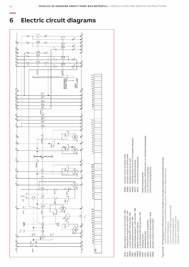
-BG
B2
Au
xilia
ry s
wit
ch o
n sw
itch
sh
aft
-BG
B3
Au
xilia
ry s
wit
ch o
n sw
itch
sh
aft
-BG
T3
Au
xilia
ry s
wit
ch a
t c.
b.-
uni
t-B
GB
4 Fl
eeti
ng
co
ntac
t 35
ms
for
c.b
. tri
pp
ed in
dic
atio
n-B
GT
2 Li
mit
sw
itch
tes
t p
osi
tio
n-B
GT
1 Li
mit
sw
itch
ser
vice
po
siti
on
Mo
de
of
pre
sent
atio
n:
Au
xilia
ry s
wit
ch -
BG
S1
sho
wn
for
c.b
.-m
ech
anis
m d
isch
arg
edC
.b.-
uni
t in
ser
vice
po
siti
on
Co
ntro
l wir
ing
plu
g 5
8-p
ole
Fig
ure
5/1
0:
Wir
ing
dia
gra
m f
or
VD
4 va
cuu
m c
ircu
it-b
reak
er o
n m
anu
ally
mo
veab
le w
ith
dra
wab
le a
ssem
bly
-
Typ
e B
of
wit
hd
raw
tru
ck o
r/an
d w
ith
au
xilia
ry s
wit
ch -
BG
T3
at w
ith
dra
wab
le t
ruck
-
Ma
xim
um
of
equ
ipm
ent
-
Au
xilia
ry s
wit
ch -
BG
B3
free
ly le
ad t
hro
ug
h
- C
on
tro
l wir
ing
plu
g 6
4-p
ole
-
Use
in O
neF
it r
etro
fill
solu
tio
n
- D
raw
ing
no
.: G
CE
200
915
3
-RLE
2 B
lock
mag
net
on
tru
ck w
ith
rect
ifie
r -T
B5
-RLE
1 C
losi
ng
blo
ck m
agn
et w
ith
rect
ifie
r -T
B4
-MB
O1
1. S
hu
nt r
elea
se O
FF w
ith
rect
ifie
r -T
B1
-MB
C
Clo
sin
g r
elea
se w
ith
rect
ifie
r -T
B3
-MB
U
Un
der
volt
age
rele
ase
U<
wit
h re
ctif
ier
-TB
6-M
BO
3 In
dir
ect
ove
rcu
rren
t re
leas
e-M
BO
2 2.
Sh
unt
rel
ease
OFF
wit
h re
ctif
ier
-TB
2-M
AS
Ch
arg
ing
mo
tor
-KFN
A
ntip
um
pin
g r
elay
-BG
S1
Au
xilia
ry s
wit
ch o
n m
ech
anis
m-B
GL1
A
uxi
liary
sw
itch
on
blo
ck m
agn
et -
RLE
1-B
GB
1 A
uxi
liary
sw
itch
on
swit
ch s
haf
t
—6 Electric circuit diagrams
M ED I U M VO LTAG E S ER V I CE 33
—7. Application of the X-ray regulations
One of the physical properties of vacuum insulation is the possibility of X-ray emissions when the contact gap is open. The specified test performed by the Physikalisch-Technische Bundesanstalt (PTB) in Braunschweig demonstrates that the local dosage output of 1 µSv/h at a distance of 10 cm from the touchable surface is not exceeded when the rated voltage is applied.The results are as follows:• Testing of the switching device or the vacuum
interrupter to VDE 0671 part 100 or IEC 62271-100 at the relevant rated power frequency withstand voltage may only be performed by trained personnel observing the stipulations of the EU basic standard (Directive 96/29/Euratom of the Council of 13 May 1996 (ABI.L 159 of 29 June 1996)).
• Application of the rated voltage specified for the switching device by VDE 0671 part 100 or IEC 62271-100 is completely safe.
• Higher voltages than the rated voltage or DC test voltage specified in VDE or IEC standards must not be applied!
• The containment of the above mentioned local dosage output with the vacuum interrupter in the open position is dependent on maintenance of the specified distance between the contacts (which is automatically ensured with correct mechanism function and force transmission).
• Safety clearances must be maintained.
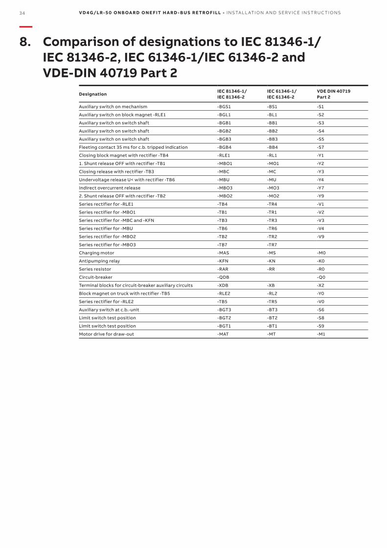
34 V D 4 G/LR- 5 0 O N B OA R D O N E F IT H A R D - B U S R E TRO F I LL - I NS TA L L ATI O N A N D SER V I CE I NS TR U C TI O NS
—8. Comparison of designations to IEC 81346-1/ IEC 81346-2, IEC 61346-1/IEC 61346-2 and VDE-DIN 40719 Part 2
DesignationIEC 81346-1/IEC 81346-2
IEC 61346-1/IEC 61346-2
VDE DIN 40719 Part 2
Auxiliary switch on mechanism -BGS1 -BS1 -S1
Auxiliary switch on block magnet -RLE1 -BGL1 -BL1 -S2
Auxiliary switch on switch shaft -BGB1 -BB1 -S3
Auxiliary switch on switch shaft -BGB2 -BB2 -S4
Auxiliary switch on switch shaft -BGB3 -BB3 -S5
Fleeting contact 35 ms for c.b. tripped indication -BGB4 -BB4 -S7
Closing block magnet with rectifier -TB4 -RLE1 -RL1 -Y1
1. Shunt release OFF with rectifier -TB1 -MBO1 -MO1 -Y2
Closing release with rectifier -TB3 -MBC -MC -Y3
Undervoltage release U< with rectifier -TB6 -MBU -MU -Y4
Indirect overcurrent release -MBO3 -MO3 -Y7
2. Shunt release OFF with rectifier -TB2 -MBO2 -MO2 -Y9
Series rectifier for -RLE1 -TB4 -TR4 -V1
Series rectifier for -MBO1 -TB1 -TR1 -V2
Series rectifier for -MBC and -KFN -TB3 -TR3 -V3
Series rectifier for -MBU -TB6 -TR6 -V4
Series rectifier for -MBO2 -TB2 -TR2 -V9
Series rectifier for -MBO3 -TB7 -TR7
Charging motor -MAS -MS -M0
Antipumping relay -KFN -KN -K0
Series resistor -RAR -RR -R0
Circuit-breaker -QDB -Q0
Terminal blocks for circuit-breaker auxiliary circuits -XDB -XB -X2
Block magnet on truck with rectifier -TB5 -RLE2 -RL2 -Y0
Series rectifier for -RLE2 -TB5 -TR5 -V0
Auxiliary switch at c.b.-unit -BGT3 -BT3 -S6
Limit switch test position -BGT2 -BT2 -S8
Limit switch test position -BGT1 -BT1 -S9
Motor drive for draw-out -MAT -MT -M1

1VCD60
1621
- R
ev. -
, en
- In
stru
ctio
n M
anu
al -
20
17.0
9 (V
D4
G/L
R-5
0) (
gs)
—Your Service sales contact: www.abb.com/contactsMore Service information: http://new.abb.com/service
VD4G webpage:
—The data and illustrations are not binding. We reserve the right to make changes without notice in the course of technical development of the product.
© Copyright 2017 ABB. All rights reserved.
—Contact us