Embed Size (px)
Citation preview
Installation manual
GBMS-P575-6.R3
PNEUMATIC SPOOL VALVE ISLANDSby field bus with the following protocol
MEGA - AS-Interfaceversion 3.0
NTERFACE

2
AS-Interface version 3.0
CAUTION
To avoid malfunction of the bus system, please check on any valve island
• for correct addressing and speed parameters.
• All installation, adjustment and maintenance operations must be carried out by qualified personnel.
A separate Declaration of Incorporation relating to EEC-Directive 89/392/EEC Annex II B is available on request.Please provide acknowledgement number and serial numbers of products concerned.This product complies with the essential requirements of the EMC-Directive 89/336/EEC and amendments. Aseparate Declaration of Conformity is available on request.
COPYRIGHT © 2001 - ASCO/JOUCOMATIC - All right reserved
CONTENTS Page
1. The BUSLINK MEGA system with the AS-Interface protocol ______________________________________ 3
2. Components of system ____________________________________________________________________ 5
2.1 Functional description ______________________________________________________________ 52.2 Arrangement of components _________________________________________________________ 52.3 Dimensions - Mounting______________________________________________________________ 62.4 MEGA island code with one AS-Interface unit ____________________________________________ 72.5 MEGA island code with 2 or 3 AS-Interface units _________________________________________ 82.6 Joinable solenoid air operated MEGA spool valves ________________________________________ 92.7 Auxiliary manual operator____________________________________________________________ 10
3. Mounting of MEGA BUSLINK with AS-Interface ________________________________________________ 12
3.1 Mounting ________________________________________________________________________ 123.2 Pneumatic connection ______________________________________________________________ 12
4. Electrical connection ______________________________________________________________________ 15
4.1 General ________________________________________________________________________ 154.2 Power supply _____________________________________________________________________ 154.3 Connection of inputs ________________________________________________________________ 164.4 Addressing _______________________________________________________________________ 174.5 Control signals ____________________________________________________________________ 20
5. AS-Interface ________________________________________________________________________ network22
5.1 Connection of AS-Interface network____________________________________________________ 225.2 Connection to power supply __________________________________________________________ 225.3 Programming instructions____________________________________________________________ 235.4 Startup of AS-Interface network _______________________________________________________ 235.5 Diagnostics _______________________________________________________________________ 235.6 Fuses ________________________________________________________________________ 235.7 Accessories for AS-Interface _________________________________________________________ 245.8 Dimensions of accessories for AS-Interface _____________________________________________ 24
This product contains electronic components sensitive to electrostaticdischarge. If a person or an object come in contact with the electricalcomponents of the product, there will be an electrostatic charge which candamage or destroy the product.To reduce the risk of electrostatic discharge, please observe the handlingprecautions and recommendations contained in standard EN100 015-1 atall times. Do not connect or disconnect this device when it is energised.E S D
WARNINGOBSERVE PRECAUTIONS
FOR HANDLINGELECTROSTATIC
DISCHARGESENSITIVE DEVICES
3
AS-Interface version 3.0
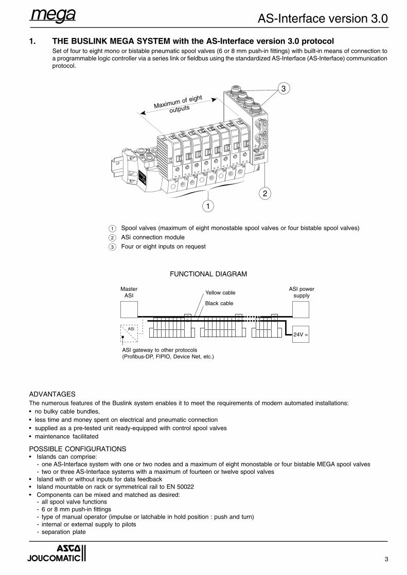
1. THE BUSLINK MEGA SYSTEM with the AS-Interface version 3.0 protocolSet of four to eight mono or bistable pneumatic spool valves (6 or 8 mm push-in fittings) with built-in means of connection toa programmable logic controller via a series link or fieldbus using the standardized AS-Interface (AS-Interface) communicationprotocol.
ADVANTAGESThe numerous features of the Buslink system enables it to meet the requirements of modern automated installations:• no bulky cable bundles,• less time and money spent on electrical and pneumatic connection• supplied as a pre-tested unit ready-equipped with control spool valves• maintenance facilitated
POSSIBLE CONFIGURATIONS• Islands can comprise:
- one AS-Interface system with one or two nodes and a maximum of eight monostable or four bistable MEGA spool valves- two or three AS-Interface systems with a maximum of fourteen or twelve spool valves
• Island with or without inputs for data feedback• Island mountable on rack or symmetrical rail to EN 50022• Components can be mixed and matched as desired:
- all spool valve functions- 6 or 8 mm push-in fittings- type of manual operator (impulse or latchable in hold position : push and turn)- internal or external supply to pilots- separation plate
1 Spool valves (maximum of eight monostable spool valves or four bistable spool valves)
2 ASi connection module
3 Four or eight inputs on request
FUNCTIONAL DIAGRAM
3
2
1
POWER
FAULT
Maximum of eight
outputs
MasterASI
ASi
24V =
Yellow cable
Black cable
ASI gateway to other protocols(Profibus-DP, FIPIO, Device Net, etc.)
ASI powersupply

4
AS-Interface version 3.0
COMMUNICATION CHARACTERISTICSCommunication protocol AS-Interface V3.0 (simple addressing)Profile version with inputs = FE78 / version without inputs = FE88Transmission Flat AS-Interface cable (2 wires) or cable (5 wires)Max. number of spool valve islands 31 nodesNumber of valves per island 4 to 8 spool valvesMax. number of inputs per interface 8 inputs for 2- or 3-wire PNP sensorsMax. bus cable length 100 m (300 m with repeater)Island addressing (participants) infrared control panel or jack plugCompatibility with control system no modification of current programmesStatus indication LED
ELECTRICAL CHARACTERISTICSSupply voltage 24 V DC, ±10% at the island (max. ripple ratio: 10 %).
Supply to the valves with an additional flat AS-Interface cable,(black, 2 wires) class 3 (PELV).
Max. consumption 75 mA per coil on power supply (black cable)<300mA per node on AS-Interface bus cable (yellow cable)
Protection IP65 (coil insulation class: F)Electrical insulation optocouplersPeak voltage suppression integrated in the island for each coilBus connection (IN/OUT) and 24 V supply vampire-type panel connector for yellow and black cableEarth connection earthing screw on the connection module with inputsElectromagnetic compatibility in accordance with EU directive EMC 89/336/EEC
CE markINPUT CHARACTERISTICSInput connection 5-pin female panel connector M12Supply voltage related to bus supplyProtection / short circuit by internal current limitationConsumption 9 mA per input with 24V DCConsumption maxi. sensors 40 mA per node
Indication 1 yellow LED per input (ON = input on)
PNEUMATIC CHARACTERISTICS (see page 9)
AS-Interfacemaster yellow cable
black cable
AS-Interface gateway to other protocols(Profibus-DP, FIPIO, Device Net etc.)
AS-Interfacepower supply
■ Pneumatic spool valve island for data exchange the standardisedAS interface version 3.0 protocol.
■ Up to 8 spool valves can be linked to one AS-Interface.■ Easy cabling with instant vampire-type connectors and flat profiled
2-wire cables.■ Connection of 4 to 8 inputs for sensor status readback.■ IP65 protection allowing for direct mounting on machines, close to
the actuators.■ High performance, modular, easy-to-install unit with LED indicators
for easy diagnostic analysis and maintenance.■ The MEGA-AS-Interface version 3.0 island is provided with individual
AS-Interface connectors for direct installation and piloting of spoolvalves with 3-pin solenoid coils to DIN 46244 or ISO 4400 (max. 7.2W).Pneumatically operated spool valves and general purpose valvescan be installed on one AS-Interface network.Individual AS-Interface connectors: see leaflet P522.
COMBINATIONS● MEGA-AS-Interface islands can be grouped as follows:
- 1 AS-Interface unit with 1 or 2 nodes and 4 bistable or max. 8monostable MEGA spool valves (see following page).
- 2 or 3 AS-Interface units with max. 14 or 12 spool valves.● Spool valve island with or without inputs for data feedback.● Frame or DIN EN 50022 rail mounting.● Optional mixing of:
- all spool valve functions,- 6 or 8 mm O.D. instant fittings.- Different types of manual override: impulse-type or locking push/turn type.- Internal and external pilot pressure supply.- Pressure separation plate and intermediate pressure supply module.
ASi
24V =
5
AS-Interface version 3.0
2. COMPONENTS OF SYSTEM
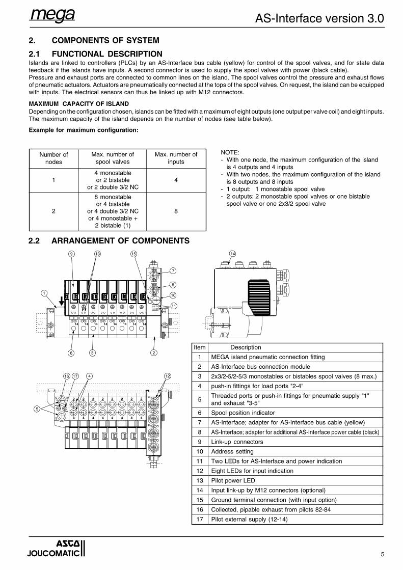
2.1 FUNCTIONAL DESCRIPTIONIslands are linked to controllers (PLCs) by an AS-Interface bus cable (yellow) for control of the spool valves, and for state datafeedback if the islands have inputs. A second connector is used to supply the spool valves with power (black cable).Pressure and exhaust ports are connected to common lines on the island. The spool valves control the pressure and exhaust flowsof pneumatic actuators. Actuators are pneumatically connected at the tops of the spool valves. On request, the island can be equippedwith inputs. The electrical sensors can thus be linked up with M12 connectors.
MAXIMUM CAPACITY OF ISLANDDepending on the configuration chosen, islands can be fitted with a maximum of eight outputs (one output per valve coil) and eight inputs.The maximum capacity of the island depends on the number of nodes (see table below).
Example for maximum configuration:
NOTE:- With one node, the maximum configuration of the island
is 4 outputs and 4 inputs- With two nodes, the maximum configuration of the island
is 8 outputs and 8 inputs- 1 output: 1 monostable spool valve- 2 outputs: 2 monostable spool valves or one bistable
spool valve or one 2x3/2 spool valve
2.2 ARRANGEMENT OF COMPONENTS
Item Description
1 MEGA island pneumatic connection fitting
2 AS-Interface bus connection module
3 2x3/2-5/2-5/3 monostables or bistables spool valves (8 max.)
4 push-in fittings for load ports "2-4"
5Threaded ports or push-in fittings for pneumatic supply "1"and exhaust "3-5"
6 Spool position indicator
7 AS-Interface; adapter for AS-Interface bus cable (yellow)
8 AS-Interface; adapter for additional AS-Interface power cable (black)
9 Link-up connectors
10 Address setting
11 Two LEDs for AS-Interface and power indication
12 Eight LEDs for input indication
13 Pilot power LED
14 Input link-up by M12 connectors (optional)
15 Ground terminal connection (with input option)
16 Collected, pipable exhaust from pilots 82-84
17 Pilot external supply (12-14)
14 14 14 14 14 14
5 3
1
2
4
2
4
2
4
2
4
2
4
2
4
82-84
12-14
14 1312 11
22 2124 23
14 14
2
4
2
4
ASi
24V
15
2
4
36
1
5
7
8
10
11
14
1217
139
16
Number ofnodes
1
2
Max. number ofspool valves
Max. number ofinputs
4 monostableor 2 bistable
or 2 double 3/2 NC4
8 monostableor 4 bistable
or 4 double 3/2 NCor 4 monostable +
2 bistable (1)
8
6
AS-Interface version 3.0
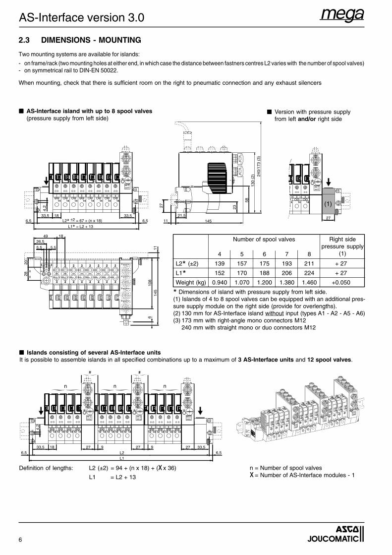
■■■■■ Islands consisting of several AS-Interface unitsIt is possible to assemble islands in all specified combinations up to a maximum of 3 AS-Interface units and 12 spool valves.
n = Number of spool valvesx = Number of AS-Interface modules - 1
Definition of lengths: L2 (±2) = 94 + (n x 18) + (x x 36)
L1 = L2 + 13
■■■■■ AS-Interface island with up to 8 spool valves(pressure supply from left side)
■■■■■ Version with pressure supplyfrom left and/or right side
2.3 DIMENSIONS - MOUNTING
Two mounting systems are available for islands:
- on frame/rack (two mounting holes at either end, in which case the distance between fastners centres L2 varies with the number of spool valves)- on symmetrical rail to DIN-EN 50022.
When mounting, check that there is sufficient room on the right to pneumatic connection and any exhaust silencers
L2* ±2 = 67 + (n x 18)33,5 18
L1* = L2 + 13
33,511
21,5
27 23
58
184926,5
5,5
14 14 14 14 14 14
5 3
1
2
4
2
4
2
4
2
4
2
4
2
4
82-84
12-14
108
6,5 6,5
5,5 1114
5
2028
4,2
==
240/
173
(3)
145
130
(2)
14 1312 11
22 2124 23
14 14
2
4
2
4
6
ASi
24V
14 14 14
27
ASi
24V
(1)
33,5 18L2L1
33,5
14 14 14 14
27
ASi
24V
6,56,5
12 12 12 12
927927
4,2
14 14 14 14
ASi
24V
12 12 12 1214 14 14 14
ASi
24V
12 12 12 12
n n n
4 5 6 7 8
L2* (±2) 139 157 175 193 211 + 27
L1* 152 170 188 206 224 + 27
Weight (kg) 0.940 1.070 1.200 1.380 1.460 +0.050
Number of spool valves Right sidepressure supply
(1)
* Dimensions of island with pressure supply from left side.(1) Islands of 4 to 8 spool valves can be equipped with an additional pres-sure supply module on the right side (provide for overlengths).(2) 130 mm for AS-Interface island without input (types A1 - A2 - A5 - A6)(3) 173 mm with right-angle mono connectors M12
240 mm with straight mono or duo connectors M12
7
AS-Interface version 3.0
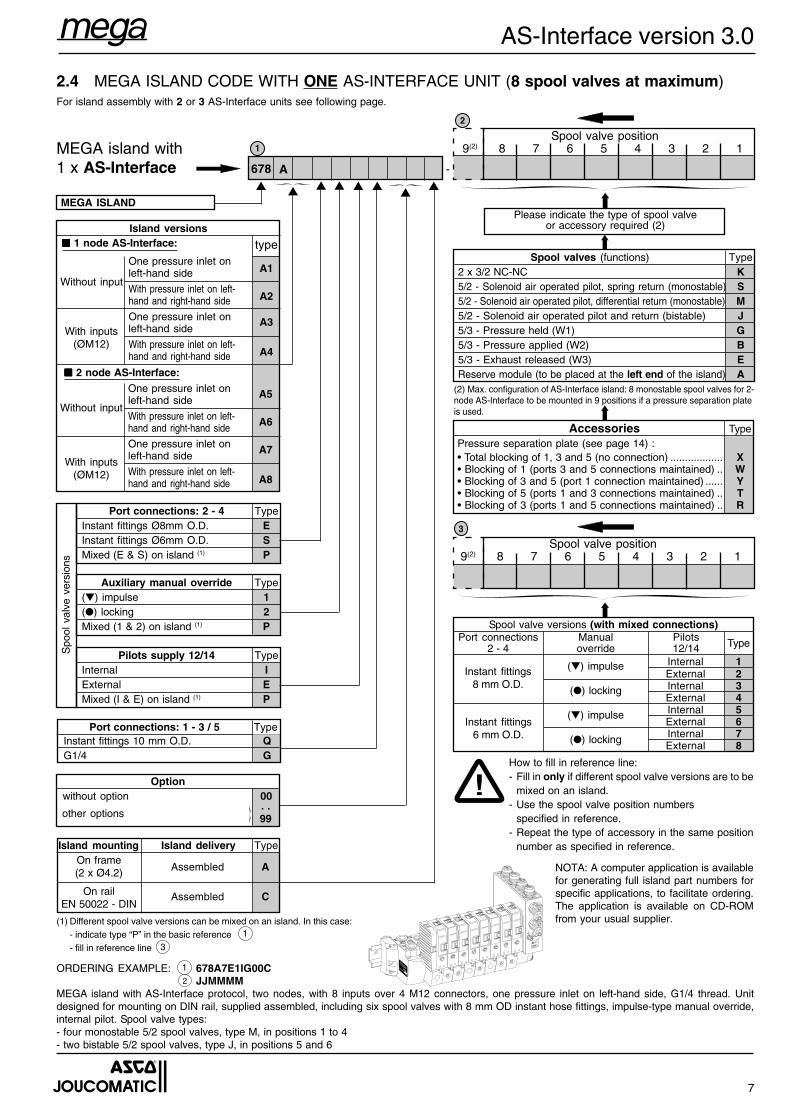
(1) Different spool valve versions can be mixed on an island. In this case:- indicate type “P” in the basic reference- fill in reference line
ORDERING EXAMPLE: 678A7E1IG00CJJMMMM
MEGA island with AS-Interface protocol, two nodes, with 8 inputs over 4 M12 connectors, one pressure inlet on left-hand side, G1/4 thread. Unitdesigned for mounting on DIN rail, supplied assembled, including six spool valves with 8 mm OD instant hose fittings, impulse-type manual override,internal pilot. Spool valve types:- four monostable 5/2 spool valves, type M, in positions 1 to 4- two bistable 5/2 spool valves, type J, in positions 5 and 6
How to fill in reference line:- Fill in only if different spool valve versions are to be
mixed on an island.- Use the spool valve position numbers
specified in reference.- Repeat the type of accessory in the same position
number as specified in reference.
Spool valve versions (with mixed connections)
TypePort connections2 - 4
Manualoverride
Pilots12/14
(▼) impulse
(●) locking
(▼) impulse
(●) locking
Instant fittings8 mm O.D.
Instant fittings6 mm O.D.
Port connections: 1 - 3 / 5 Type
On frame(2 x Ø4.2)
On railEN 50022 - DIN
Spo
ol v
alve
ver
sion
s
One pressure inlet onleft-hand side
With pressure inlet on left-hand and right-hand side
One pressure inlet onleft-hand side
With pressure inlet on left-hand and right-hand side
One pressure inlet onleft-hand side
With pressure inlet on left-hand and right-hand side
One pressure inlet onleft-hand side
With pressure inlet on left-hand and right-hand side
Island versions
MEGA ISLAND
Without input
With inputs(ØM12)
■■■■■ 2 node AS-Interface:
Without input
With inputs(ØM12)
Spool valve position9(2) 8 7 6 5 4 3 2 1
Please indicate the type of spool valveor accessory required (2)
Spool valve position9(2) 8 7 6 5 4 3 2 1MEGA island with
1 x AS-Interface
!
3
2
1
A5
A6
A7
A8
-
▼ ▼ ▼ ▼ ▼ ▼
678
(2) Max. configuration of AS-Interface island: 8 monostable spool valves for 2-node AS-Interface to be mounted in 9 positions if a pressure separation plateis used.
▼
A1
A2
A3
A4
type
2.4 MEGA ISLAND CODE WITH ONE AS-INTERFACE UNIT (8 spool valves at maximum)For island assembly with 2 or 3 AS-Interface units see following page.
A
▼
NOTA: A computer application is availablefor generating full island part numbers forspecific applications, to facilitate ordering.The application is available on CD-ROMfrom your usual supplier.
Spool valves (functions) Type2 x 3/2 NC-NC K5/2 - Solenoid air operated pilot, spring return (monostable) S5/2 - Solenoid air operated pilot, differential return (monostable) M5/2 - Solenoid air operated pilot and return (bistable) J5/3 - Pressure held (W1) G5/3 - Pressure applied (W2) B5/3 - Exhaust released (W3) EReserve module (to be placed at the left end of the island) A
Accessories TypePressure separation plate (see page 14) :• Total blocking of 1, 3 and 5 (no connection) .................. X• Blocking of 1 (ports 3 and 5 connections maintained) .. W• Blocking of 3 and 5 (port 1 connection maintained) ...... Y• Blocking of 5 (ports 1 and 3 connections maintained) .. T• Blocking of 3 (ports 1 and 5 connections maintained) .. RPort connections: 2 - 4 Type
Instant fittings Ø8mm O.D. EInstant fittings Ø6mm O.D. SMixed (E & S) on island (1) P
Auxiliary manual override Type(▼) impulse 1(●) locking 2Mixed (1 & 2) on island (1) P
Pilots supply 12/14 TypeInternal IExternal EMixed (I & E) on island (1) P
Instant fittings 10 mm O.D. QG1/4 G
Optionwithout option 00
other options. .99
Assembled A
Assembled C
Island mounting Island delivery Type
Internal 1External 2Internal 3External 4Internal 5External 6Internal 7External 8
■■■■■ 1 node AS-Interface:
1
3
12
8
AS-Interface version 3.0
MEGA island with2 or 3 AS-Interfaces
With pressure inlet on left-hand andright-hand side
With pressure inlet on left-hand andright-hand side
With pressure inlet on left-hand andright-hand side
With pressure inlet on left-hand andright-hand side
Island versions■ ■ ■ ■ ■ 1 node AS-Interface:
MEGA ISLAND
Without input
With inputs(ØM12)
■■■■■ 2 node AS-Interface:
Without input
With inputs(ØM12)
Spo
ol v
alve
ver
sion
s
On frame(2 x Ø4.2)
On railEN 50022 - DIN
Island mounting Island delivery Type
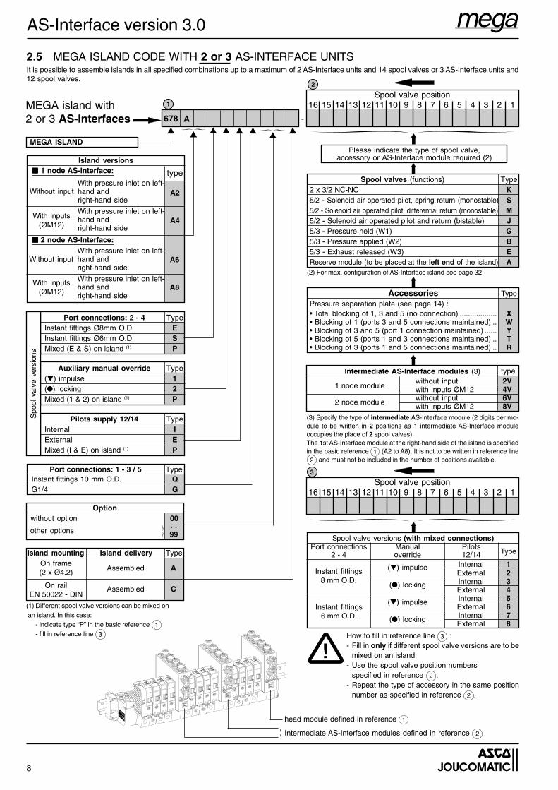
How to fill in reference line 3 :- Fill in only if different spool valve versions are to be
mixed on an island.- Use the spool valve position numbers
specified in reference 2 .- Repeat the type of accessory in the same position
number as specified in reference 2 .
Spool valve versions (with mixed connections)
TypePort connections
2 - 4Manualoverride
Pilots12/14
(▼) impulse
(●) locking
(▼) impulse
(●) locking
Instant fittings8 mm O.D.
Instant fittings6 mm O.D.
Spool valve position16 15 14 13 12 11 10 9 8 7 6 5 4 3 2 1
(3) Specify the type of intermediate AS-Interface module (2 digits per mo-dule to be written in 2 positions as 1 intermediate AS-Interface moduleoccupies the place of 2 spool valves).The 1st AS-Interface module at the right-hand side of the island is specifiedin the basic reference 1 (A2 to A8). It is not to be written in reference line2 and must not be included in the number of positions available.
Intermediate AS-Interface modules (3)
1 node module
2 node module
Please indicate the type of spool valve,accessory or AS-Interface module required (2)
Spool valve position16 15 14 13 12 11 10 9 8 7 6 5 4 3 2 1
!
3
2
1
-
▼ ▼ ▼ ▼ ▼ ▼
678
(2) For max. configuration of AS-Interface island see page 32
▼
2.5 MEGA ISLAND CODE WITH 2 or 3 AS-INTERFACE UNITSIt is possible to assemble islands in all specified combinations up to a maximum of 2 AS-Interface units and 14 spool valves or 3 AS-Interface units and12 spool valves.
A
▼
type
A6
A8
A2
A4
typeSpool valves (functions) Type
2 x 3/2 NC-NC K5/2 - Solenoid air operated pilot, spring return (monostable) S5/2 - Solenoid air operated pilot, differential return (monostable) M5/2 - Solenoid air operated pilot and return (bistable) J5/3 - Pressure held (W1) G5/3 - Pressure applied (W2) B5/3 - Exhaust released (W3) EReserve module (to be placed at the left end of the island) A
without input 2Vwith inputs ØM12 4Vwithout input 6Vwith inputs ØM12 8V
Internal 1External 2Internal 3External 4Internal 5External 6Internal 7External 8
head module defined in reference 1
Intermediate AS-Interface modules defined in reference 2
(1) Different spool valve versions can be mixed on an island. In this case:
- indicate type “P” in the basic reference 1- fill in reference line 3
Optionwithout option 00
other options. .99
Assembled A
Assembled C
Instant fittings 10 mm O.D. QG1/4 G
Port connections: 1 - 3 / 5 Type
Port connections: 2 - 4 TypeInstant fittings Ø8mm O.D. EInstant fittings Ø6mm O.D. SMixed (E & S) on island (1) P
Auxiliary manual override Type(▼) impulse 1(●) locking 2Mixed (1 & 2) on island (1) P
Pilots supply 12/14 TypeInternal IExternal EMixed (I & E) on island (1) P
Accessories TypePressure separation plate (see page 14) :• Total blocking of 1, 3 and 5 (no connection) .................. X• Blocking of 1 (ports 3 and 5 connections maintained) .. W• Blocking of 3 and 5 (port 1 connection maintained) ...... Y• Blocking of 5 (ports 1 and 3 connections maintained) .. T• Blocking of 3 (ports 1 and 5 connections maintained) .. R
9
AS-Interface version 3.0
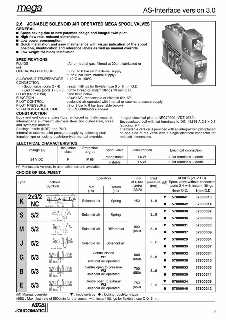
2.6 JOINABLE SOLENOID AIR OPERATED MEGA SPOOL VALVESGENERAL■ Space saving due to new patented design and integral twin pilot.■ High flow rate, reduced dimensions.■ Low power consumption.■ Quick installation and easy maintenance with visual indication of the spool
position, identification and reference labels as well as manual override.■ Low weight for block installation.
SPECIFICATIONSFLUIDS : Air or neutral gas, filtered at 30µm, lubricated ornotOPERATING PRESSURE : -0.95 to 8 bar (with external supply)
: 3 to 8 bar (with internal supply)ALLOWABLE TEMPERATURE : -10°C to +50°CCONNECTION
- Spool valve (ports 2 - 4) : instant fittings for flexible hose 6 or 8 mm O.D.- End covers (ports 1 - 3 - 5) : G1/4 thread or instant fittings 10 mm O.D.
FLOW (Qv at 6 bar) : see table belowFUNCTION : 2x3/2 NC, monostable or bistable 5/2, 5/3PILOT CONTROL : solenoid air operated with internal or external pressure supplyPILOT PRESSURE : 2 or 3 bar to 8 bar (see table below)VIBRATION FATIGUE LIMIT : to EN 60068-2-6 standard
CODES (24 V DC)Spool valve without connectorports 2-4 with instant fittings
▼ 57800041 57800013
● 57800042 57800014
▼ 57800030 57800002
● 57800036 57800008
▼ 57800031 57800003
● 57800037 57800009
▼ 57800029 57800001
● 57800035 57800007
▼ 57800032 57800004
● 57800038 57800010
▼ 57800033 57800005
● 57800039 57800011
▼ 57800034 57800006
● 57800040 57800012
Solenoid air Solenoid air
Electrical connectionSpool valve
monostable
bistable
Protectiondegree
Insulationclass ConsumptionVoltage (*)
2 flat terminals + earth
3 flat terminals + earthIP 65F24 V DC
CHOICE OF EQUIPMENT
Return(12)
Pilot(14)
5/2
5/3
Centre closedW1
solenoid air operated
Centre open to exhaustW3
solenoid air operated
Centre open to pressureW2
solenoid air operated
900(550)
Solenoid air Differential
FunctionsSymbols
Flowat 6 bar(l/min)(ANR)
Operators(M)
14 2
35
4
182/8412/14
Solenoid air Spring
14 2
35
4
182/84
12
12/14
12
12/14
2
35
4
182/84
14
24
182/84
1214
1412
35
24
182/84
1214
1412
35
24
182/84
1214
1412
35
(M) Manual override ▼ : impulse-type ● : locking, push/turn-type(550) : Max. flow rate of 550l/min for the version with instant fittings for flexible hose O.D. 6mm.
6mm O.D. 8mm O.D.
1.5 W
2x3/2NC
Solenoid air Spring
Pilotpressure
(bar)
450
600(550)
700(550)
750(550)
4...8
3...8
3...8
2...8
3...8
3...8
3...8
5/2
5/2
5/3
5/3
M
B
S
G
E
K
Type
J
ELECTRICAL CHARACTERISTICS
CONSTRUCTIONBody and end covers: glass-fibre reinforced synthetic material.Internal parts: aluminium, stainless steel, zinc-plated steel, brassand synthetic material.Sealings: nitrile (NBR) and PUR.Internal or external pilot pressure supply by selecting sealImpulse-type or locking push/turn-type manual override.
Integral electrical pilot to NFC79300 (VDE 0580).Encapsulated coil with flat terminals to DIN 46244 A 2.8 x 0.5(spacing: 9.4 mm).The bistable version is provided with an integral twin pilot placedon one side of the valve with a single electrical connector forreduced dimensions.
1.6 W
(*) Monostable version, in alternative current, available
10
AS-Interface version 3.0
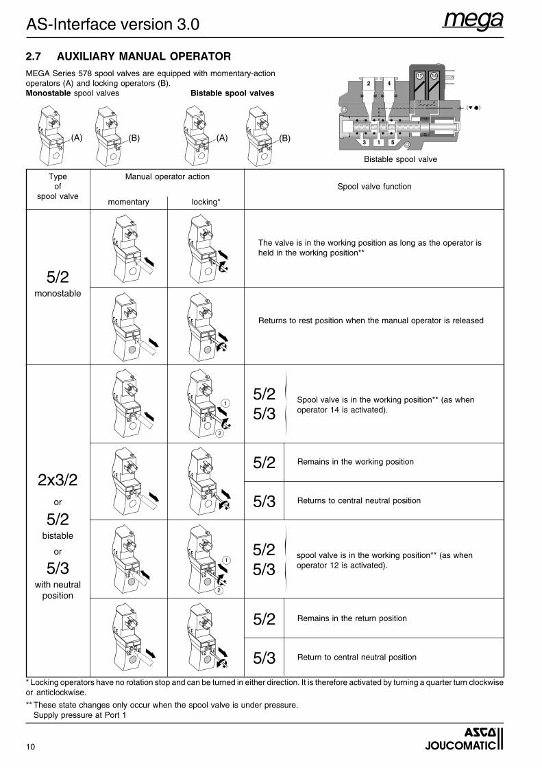
2.7 AUXILIARY MANUAL OPERATORMEGA Series 578 spool valves are equipped with momentary-actionoperators (A) and locking operators (B).Monostable spool valves Bistable spool valves
Typeof
spool valve
Manual operator actionSpool valve function
5/2monostable
2x3/2or
5/2bistable
or
5/3with neutral
position
The valve is in the working position as long as the operator isheld in the working position**
Returns to rest position when the manual operator is released
Spool valve is in the working position** (as whenoperator 14 is activated).
5/25/3
5/2 Remains in the working position
5/3 Returns to central neutral position
5/25/3
5/2 Remains in the return position
5/3 Return to central neutral position
* Locking operators have no rotation stop and can be turned in either direction. It is therefore activated by turning a quarter turn clockwiseor anticlockwise.
** These state changes only occur when the spool valve is under pressure.Supply pressure at Port 1
spool valve is in the working position** (as whenoperator 12 is activated).
3 1 5
12 14
2 4
(A) (A)
momentary locking*
(B) (B)
1
2
1
2
Bistable spool valve
11
AS-Interface version 3.0
INT
EX
T
INT
EX
T
MOUNTING AND PNEUMATIC ACCESSORIES
Accessory Description Code
DIN EN50022 rail
Set of 10 connecting bolts 18 mm long (for 5 spool valves)(Note: Each spool valve is delivered with connecting bolts)
Set of 10 instant reducing fittings 8 / 6 mm O.D. (1)
Exhaust silencer, male thread (2)
Sintered bronze exhaust silencer for direct mounting to ports withinstant fittings 10 mm O.D. (3)
Set of 17 clip-on ID labels for spool valves and VCS connectors(Note: each component is supplied with 2 ID labels at delivery)
88157858
33400033
88157893
88157887
34600407
34600002
88157826
88157851
1 m
5 x 1 m
1m
(1) For mounting to ports 2 – 4 of spool valves with 8 mm O.D. instant fittings for 6 mm O.D. flexible tube(2) Exhaust silencer for ports 3/5 of G1/4 threaded end covers (see page 7)(3) Exhaust silencer for ports 3/5 of end covers with instant fittings 10 mm O.D. (see page 7)
x10
x10
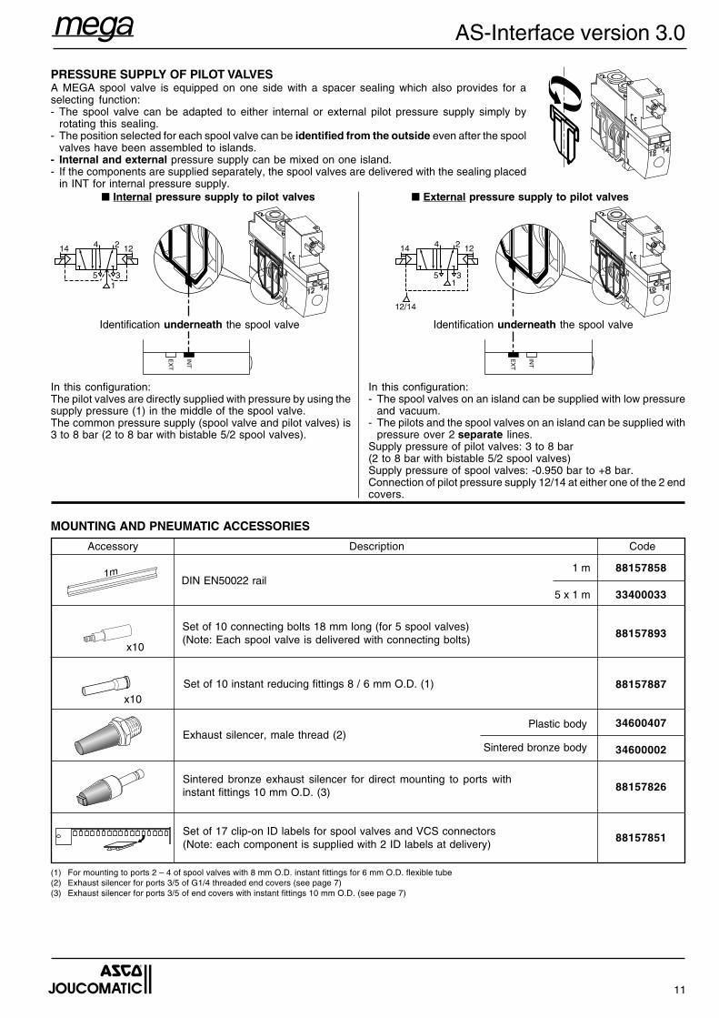
PRESSURE SUPPLY OF PILOT VALVESA MEGA spool valve is equipped on one side with a spacer sealing which also provides for aselecting function:- The spool valve can be adapted to either internal or external pilot pressure supply simply by
rotating this sealing.- The position selected for each spool valve can be identified from the outside even after the spool
valves have been assembled to islands.- Internal and external pressure supply can be mixed on one island.- If the components are supplied separately, the spool valves are delivered with the sealing placed
in INT for internal pressure supply.■ Internal pressure supply to pilot valves ■ External pressure supply to pilot valves
Identification underneath the spool valve
In this configuration:The pilot valves are directly supplied with pressure by using thesupply pressure (1) in the middle of the spool valve.The common pressure supply (spool valve and pilot valves) is3 to 8 bar (2 to 8 bar with bistable 5/2 spool valves).
In this configuration:- The spool valves on an island can be supplied with low pressure
and vacuum.- The pilots and the spool valves on an island can be supplied with
pressure over 2 separate lines.Supply pressure of pilot valves: 3 to 8 bar(2 to 8 bar with bistable 5/2 spool valves)Supply pressure of spool valves: -0.950 bar to +8 bar.Connection of pilot pressure supply 12/14 at either one of the 2 endcovers.
Identification underneath the spool valve
Sintered bronze body
Plastic body
12
AS-Interface version 3.0
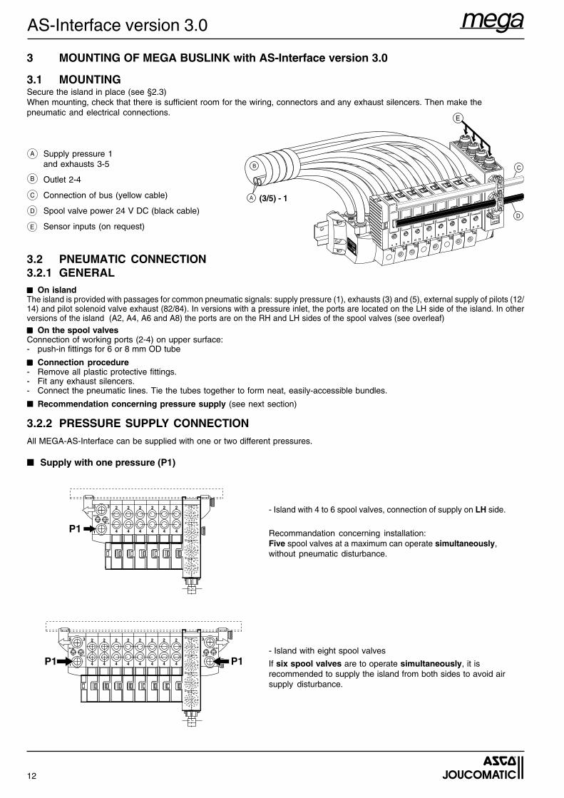
- Island with eight spool valves
If six spool valves are to operate simultaneously, it isrecommended to supply the island from both sides to avoid airsupply disturbance.
5 3
1
2
4
2
4
2
4
2
4
2
4
2
4
82-84
12-14
14 1312 11
22 2124 23
2
4
2
4P1
53
1
82-84
12-14
P1
3 MOUNTING OF MEGA BUSLINK with AS-Interface version 3.0
3.1 MOUNTINGSecure the island in place (see §2.3)When mounting, check that there is sufficient room for the wiring, connectors and any exhaust silencers. Then make thepneumatic and electrical connections.
A Supply pressure 1and exhausts 3-5
Outlet 2-4
Connection of bus (yellow cable)
Spool valve power 24 V DC (black cable)
Sensor inputs (on request)
B
C
D
E
3.2 PNEUMATIC CONNECTION3.2.1 GENERAL■■■■■ On islandThe island is provided with passages for common pneumatic signals: supply pressure (1), exhausts (3) and (5), external supply of pilots (12/14) and pilot solenoid valve exhaust (82/84). In versions with a pressure inlet, the ports are located on the LH side of the island. In otherversions of the island (A2, A4, A6 and A8) the ports are on the RH and LH sides of the spool valves (see overleaf)■■■■■ On the spool valvesConnection of working ports (2-4) on upper surface:- push-in fittings for 6 or 8 mm OD tube
■■■■■ Connection procedure- Remove all plastic protective fittings.- Fit any exhaust silencers.- Connect the pneumatic lines. Tie the tubes together to form neat, easily-accessible bundles.
■ Recommendation concerning pressure supply (see next section)
3.2.2 PRESSURE SUPPLY CONNECTIONAll MEGA-AS-Interface can be supplied with one or two different pressures.
■ Supply with one pressure (P1)
5 3
1
2
4
2
4
2
4
2
4
82-84
12-14
14 1312 11
22 2124 23
2
4
2
4P1
- Island with 4 to 6 spool valves, connection of supply on LH side.
Recommandation concerning installation:Five spool valves at a maximum can operate simultaneously,without pneumatic disturbance.
13
AS-Interface version 3.0
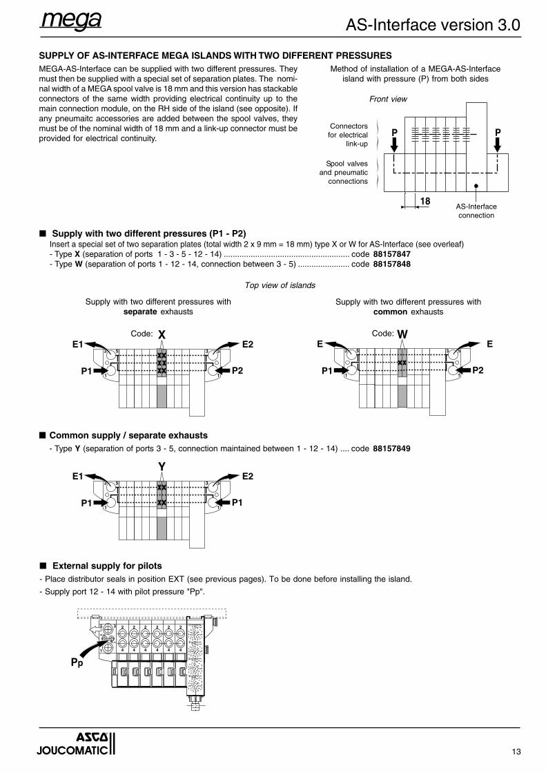
■ Supply with two different pressures (P1 - P2)Insert a special set of two separation plates (total width 2 x 9 mm = 18 mm) type X or W for AS-Interface (see overleaf)- Type X (separation of ports 1 - 3 - 5 - 12 - 14) ........................................................ code 88157847- Type W (separation of ports 1 - 12 - 14, connection between 3 - 5) ....................... code 88157848
P2
E
P1
E3
1
5 3
1
5
W
P2
E2
P1
E13
1
5 3
1
5
X
Supply with two different pressures withcommon exhausts
Supply with two different pressures withseparate exhausts
Code:Code:
■ External supply for pilots- Place distributor seals in position EXT (see previous pages). To be done before installing the island.
- Supply port 12 - 14 with pilot pressure "Pp".
■ Common supply / separate exhausts- Type Y (separation of ports 3 - 5, connection maintained between 1 - 12 - 14) .... code 88157849
P1
E2
P1
E13
1
5 3
1
5
Y
PP
18
Front view
Connectorsfor electrical
link-up
Spool valvesand pneumatic
connections
SUPPLY OF AS-INTERFACE MEGA ISLANDS WITH TWO DIFFERENT PRESSURESMEGA-AS-Interface can be supplied with two different pressures. Theymust then be supplied with a special set of separation plates. The nomi-nal width of a MEGA spool valve is 18 mm and this version has stackableconnectors of the same width providing electrical continuity up to themain connection module, on the RH side of the island (see opposite). Ifany pneumaitc accessories are added between the spool valves, theymust be of the nominal width of 18 mm and a link-up connector must beprovided for electrical continuity.
Method of installation of a MEGA-AS-Interfaceisland with pressure (P) from both sides
AS-Interfaceconnection
Top view of islands
5 3
1
2
4
2
4
2
4
2
4
82-84
12-14
14 1312 11
22 2124 23
2
4
2
4
Pp
14
AS-Interface version 3.0
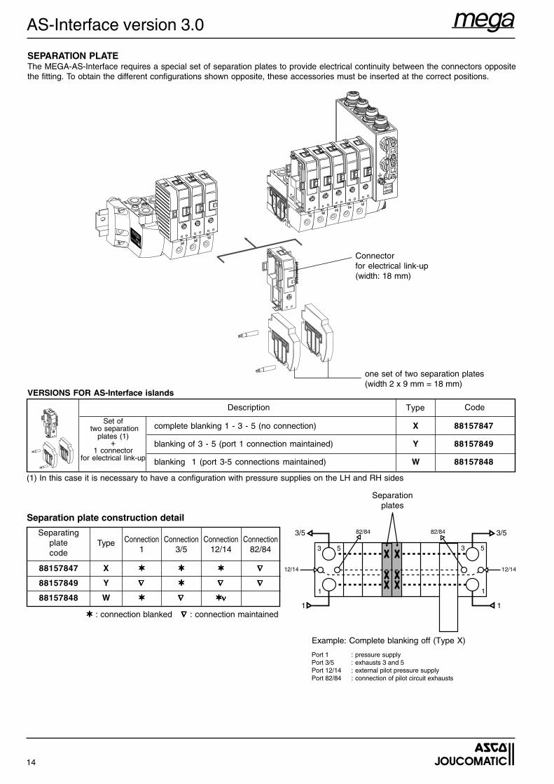
VERSIONS FOR AS-Interface islands
Description CodeType
Set of two separation
plates (1)+
1 connectorfor electrical link-up
complete blanking 1 - 3 - 5 (no connection) X 88157847
blanking of 3 - 5 (port 1 connection maintained) Y 88157849
blanking 1 (port 3-5 connections maintained) W 88157848
SEPARATION PLATEThe MEGA-AS-Interface requires a special set of separation plates to provide electrical continuity between the connectors oppositethe fitting. To obtain the different configurations shown opposite, these accessories must be inserted at the correct positions.
Separation plate construction detail
Separatingplatecode
Type Connection1
Connection3/5
Connection12/14
Connection82/84
88157847 X ✶✶✶✶✶ ✶✶✶✶✶ ✶✶✶✶✶ ∇∇∇∇∇
88157849 Y ∇∇∇∇∇ ✶✶✶✶✶ ∇∇∇∇∇ ∇∇∇∇∇
88157848 W ✶✶✶✶✶ ∇∇∇∇∇ ✶✶✶✶✶ννννν
Separationplates
Port 1 : pressure supplyPort 3/5 : exhausts 3 and 5Port 12/14 : external pilot pressure supplyPort 82/84 : connection of pilot circuit exhausts
3/5
1
12/14
82/84
3 5
1
3 5
1
82/84 3/5
1
12/14
(1) In this case it is necessary to have a configuration with pressure supplies on the LH and RH sides
Example: Complete blanking off (Type X)
Connectorfor electrical link-up(width: 18 mm)
one set of two separation plates(width 2 x 9 mm = 18 mm)
✶✶✶✶✶ : connection blanked ∇ ∇ ∇ ∇ ∇ : connection maintained
15
AS-Interface version 3.0
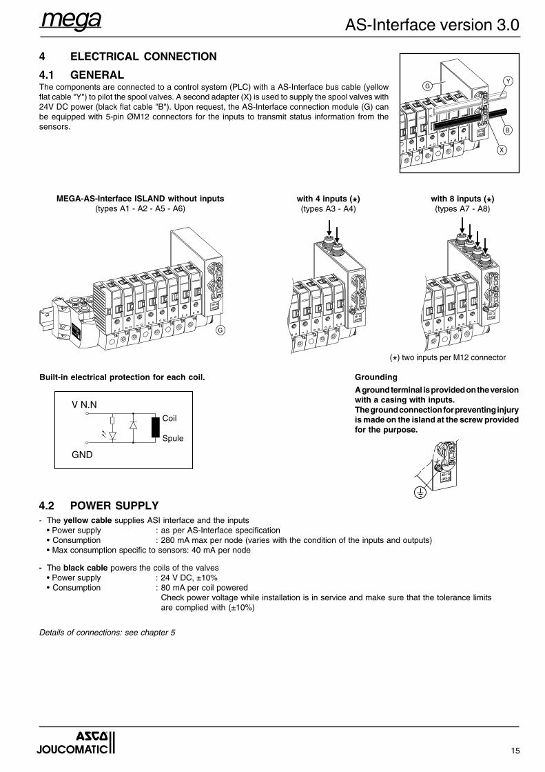
MEGA-AS-Interface ISLAND without inputs(types A1 - A2 - A5 - A6)
with 4 inputs (*)(types A3 - A4)
with 8 inputs (*)(types A7 - A8)
V N.N
GND
4 ELECTRICAL CONNECTION
4.1 GENERALThe components are connected to a control system (PLC) with a AS-Interface bus cable (yellowflat cable "Y") to pilot the spool valves. A second adapter (X) is used to supply the spool valves with24V DC power (black flat cable "B"). Upon request, the AS-Interface connection module (G) canbe equipped with 5-pin ØM12 connectors for the inputs to transmit status information from thesensors.
Coil
Spule
A ground terminal is provided on the versionwith a casing with inputs.The ground connection for preventing injuryis made on the island at the screw providedfor the purpose.
Built-in electrical protection for each coil. Grounding
4.2 POWER SUPPLY- The yellow cable supplies ASI interface and the inputs
• Power supply : as per AS-Interface specification• Consumption : 280 mA max per node (varies with the condition of the inputs and outputs)• Max consumption specific to sensors: 40 mA per node
- The black cable powers the coils of the valves• Power supply : 24 V DC, ±10%• Consumption : 80 mA per coil powered
Check power voltage while installation is in service and make sure that the tolerance limitsare complied with (±10%)
Details of connections: see chapter 5
GY
B
X
G
(*) two inputs per M12 connector
16
AS-Interface version 3.0
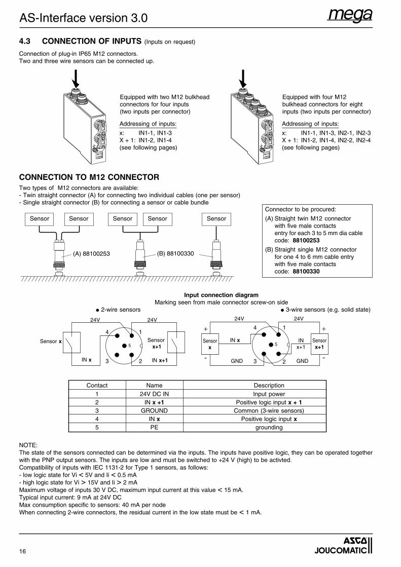
CONNECTION TO M12 CONNECTORTwo types of M12 connectors are available:- Twin straight connector (A) for connecting two individual cables (one per sensor)- Single straight connector (B) for connecting a sensor or cable bundle
(B) 88100330(A) 88100253
4.3 CONNECTION OF INPUTS (Inputs on request)
Connection of plug-in IP65 M12 connectors.Two and three wire sensors can be connected up.
Sensor Sensor Sensor Sensor Sensor
Connector to be procured:
(A) Straight twin M12 connectorwith five male contactsentry for each 3 to 5 mm dia cablecode: 88100253
(B) Straight single M12 connectorfor one 4 to 6 mm cable entrywith five male contactscode: 88100330
Contact Name Description1 24V DC IN Input power2 IN x +1 Positive logic input x + 13 GROUND Common (3-wire sensors)4 IN x Positive logic input x5 PE grounding
Input connection diagramMarking seen from male connector screw-on side
● 2-wire sensors ● 3-wire sensors (e.g. solid state)
1
2
4
3
5
+
-
+
-
INx+1
IN xSensorx
Sensorx+1
24V 24V
GND GND
1
2
4
3
5Sensor x
IN x IN x+1
Sensor x+1
24V 24V
NOTE:The state of the sensors connected can be determined via the inputs. The inputs have positive logic, they can be operated togetherwith the PNP output sensors. The inputs are low and must be switched to +24 V (high) to be activted.Compatibility of inputs with IEC 1131-2 for Type 1 sensors, as follows:- low logic state for Vi < 5V and Ii < 0.5 mA- high logic state for Vi > 15V and Ii > 2 mAMaximum voltage of inputs 30 V DC, maximum input current at this value < 15 mA.Typical input current: 9 mA at 24V DCMax consumption specific to sensors: 40 mA per nodeWhen connecting 2-wire connectors, the residual current in the low state must be < 1 mA.
Addressing of inputs:
x: IN1-1, IN1-3, IN2-1, IN2-3X + 1: IN1-2, IN1-4, IN2-2, IN2-4(see following pages)
Equipped with four M12bulkhead connectors for eightinputs (two inputs per connector)
Addressing of inputs:
x: IN1-1, IN1-3X + 1: IN1-2, IN1-4(see following pages)
Equipped with two M12 bulkheadconnectors for four inputs(two inputs per connector)
17
AS-Interface version 3.0
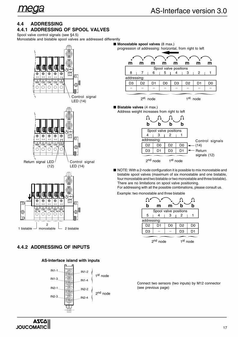
Spool valve positions8 7 6 5 4 3 2 1
1st. node
4.4 ADDRESSING4.4.1 ADDRESSING OF SPOOL VALVESSpool valve control signals (see §4.5)Monostable and bistable spool valves are addressed differently
D3 D2 D1 D0 D3 D2 D1 D0_ _ _ _ _ _ _ _
■ Bistable valves (4 max.)Address weight increases from right to left
■ NOTE: With a 2-node configuration it is possible to mix monostable andbistable spool valves (maximum of six monostable and one bistable,four monostable and two bistable or two monostable and three bistable).There are no limitations on spool valve positioning.For addressing with all the possible combinations, please consult us.
4.4.2 ADDRESSING OF INPUTS
AS-Interface island with inputs
1st node
2nd node
Connect two sensors (two inputs) by M12 connector(see previous page)
2st. node
addressing:
■ Monostable spool valves (8 max.)progression of addressing: horizontal, from right to left
14 14 14 14 14
ASi
24V
mmmmmmmm
Control signalLED (14)
14 1312 11
22 2124 23
IN1-1
IN1-3
IN1-2
IN1-4
IN2-1
IN2-3
IN2-2
IN2-4
bbbb
bbmmb14 14 14 14 14
ASi
24V
12 12 12
Example: two monostable and three bistable
1 bistable2
monostable 2 bistable
1st node2nd node
Spool valve positions4 3 2 1
D2 D0 D2 D0
D3 D1 D3 D1
addressing: Control signals(14)
Returnsignals (12)
Spool valve positions5 4 3 2 1
1st node
D2 D1 D0 D2 D0
D3 _ _ D3 D1
2nd node
addressing:
14 14 14 14 14
ASi
24V
Control signalLED (14)
Return signal LED(12)
18
AS-Interface version 3.0
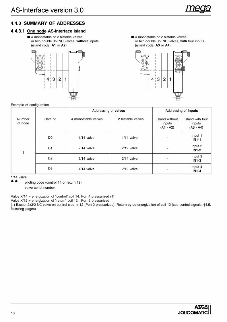
4.4.3 SUMMARY OF ADDRESSES
4.4.3.1 One node AS-Interface island
Numberof node
Data bit 4 monostable valves 2 bistable valves Island withoutinputs
(A1 - A2)
Island with fourinputs
(A3 - A4)
Addressing of valves Addressing of inputs
1/14 valve 1/14 valve -Input 1IN1-1
2/14 valve 2/12 valve -Input 2IN1-2
3/14 valve 2/14 valve -Input 3IN1-3
4/14 valve 2/12 valve -Input 4IN1-4
D0
D1
D2
D3
1
Valve X/14 = energization of "control" coil 14: Port 4 pressurized (1)Valve X/12 = energization of "return" coil 12: Port 2 pressurized(1) Except 2x3/2 NC valve on control side = 12 (Port 2 pressurized). Return by de-energization of coil 12 (see control signals, §4.5,following pages)
5 3
1
82-84
12-14
4 3 2 1
5 3
1
82-84
12-14
14 1312 11
4 3 2 1
■ 4 monostable or 2 bistable valvesor two double 3/2 NC valves, without inputs(island code: A1 or A2)
■ 4 monostable or 2 bistable valvesor two double 3/2 NC valves, with four inputs(island code: A3 or A4)
Example of configuration
1/14 valve
piloting code (control 14 or return 12)
valve serial number
▼ ▼
19
AS-Interface version 3.0
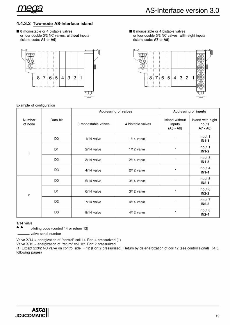
Island withoutinputs
(A5 - A6)
Island with eightinputs
(A7 - A8)
Numberof node
Data bit8 monostable valves 4 bistable valves
Addressing of valves Addressing of inputs
1/14 valve 1/14 valve - Input 1IN1-1
2/14 valve 1/12 valve - Input 1IN1-2
3/14 valve 2/14 valve - Input 3IN1-3
4/14 valve 2/12 valve - Input 4IN1-4
5/14 valve 3/14 valve - Input 5IN2-1
6/14 valve 3/12 valve - Input 6IN2-2
7/14 valve 4/14 valve - Input 7IN2-3
8/14 valve 4/12 valve - Input 8IN2-4
D0
D1
D2
D3
D0
D1
D2
D3
1
2
Valve X/14 = energization of "control" coil 14: Port 4 pressurized (1)Valve X/12 = energization of "return" coil 12: Port 2 pressurized(1) Except 2x3/2 NC valve on control side = 12 (Port 2 pressurized). Return by de-energization of coil 12 (see control signals, §4.5,following pages)
5 3
1
82-84
12-14
8 7 6 5 4 3 2 1
5 3
1
82-84
12-14
14 1312 11
22 2124 23
8 7 6 5 4 3 2 1
4.4.3.2 Two-node AS-Interface island
■ 8 monostable or 4 bistable valvesor four double 3/2 NC valves, without inputs(island code: A5 or A6)
■ 8 monostable or 4 bistable valvesor four double 3/2 NC valves, with eight inputs(island code: A7 or A8)
Example of configuration
1/14 valve
piloting code (control 14 or return 12)
valve serial number
▼ ▼
20
AS-Interface version 3.0
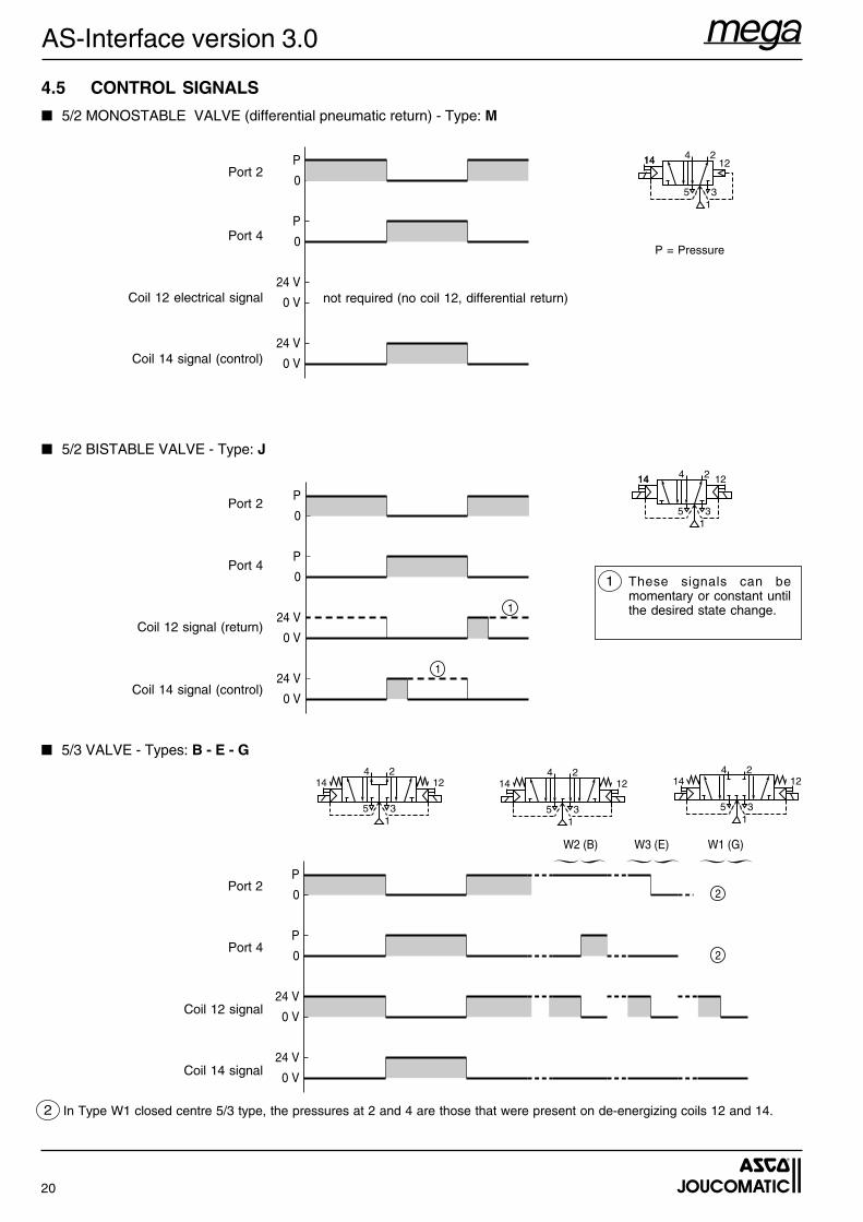
4.5 CONTROL SIGNALS
■ 5/2 MONOSTABLE VALVE (differential pneumatic return) - Type: M
■ 5/2 BISTABLE VALVE - Type: J
P
0
P
0
24 V
0 V
24 V
0 V
P
0
P
0
24 V
0 V
24 V
0 V
1
1
Port 2
Port 4
Coil 12 electrical signal not required (no coil 12, differential return)
Coil 14 signal (control)
14 1214 2
35
4
1
P = Pressure
These signals can bemomentary or constant untilthe desired state change.
1
Port 2
Coil 12 signal (return)
Port 4
Coil 14 signal (control)
14 1214 2
35
4
1
In Type W1 closed centre 5/3 type, the pressures at 2 and 4 are those that were present on de-energizing coils 12 and 14.2
P
0
P
0
24 V
0 V
24 V
0 V
2
2
W2 (B) W3 (E) W1 (G)
Port 2
Coil 14 signal
Coil 12 signal
Port 4
■ 5/3 VALVE - Types: B - E - G24
35
14 12
1
24
35
14 12
1
24
35
14 12
1
21
AS-Interface version 3.0
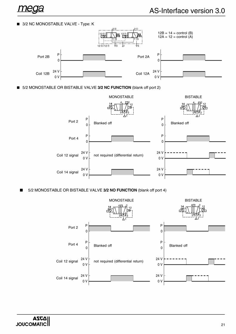
■ 3/2 NC MONOSTABLE VALVE - Type: K
P
0
24 V
0 V
P
0
P
0
24 V
0 V
24 V
0 V
P
0
P
0
24 V
0 V
24 V
0 V
Blanked off
14 1214 2
35
4
1
14 1214 2
35
4
1
BISTABLEMONOSTABLE
Port 2
Port 4
Coil 14 signal
Coil 12 signal not required (differential return)
■ 5/2 MONOSTABLE OR BISTABLE VALVE 3/2 NO FUNCTION (blank off port 4)
P
0
P
0
24 V
0 V
24 V
0 V
P
0
P
0
24 V
0 V
24 V
0 V
Blanked off Blanked off
14 1214 2
35
4
1
14 1214 2
35
4
1
MONOSTABLE BISTABLE
Port 4
Coil 14 signal
Coil 12 signal
Port 2
■ 5/2 MONOSTABLE OR BISTABLE VALVE 3/2 NC FUNCTION (blank off port 2)
not required (differential return)
Coil 12B
Port 2B
12B = 14 = control (B)12A = 12 = control (A)
P
0
24 V
0 VCoil 12A
Port 2A
Blanked off
22
AS-Interface version 3.0
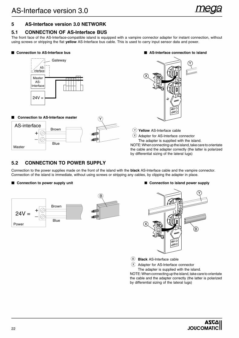
5.2 CONNECTION TO POWER SUPPLYConnection to the power supplies made on the front of the island with the black AS-Interface cable and the vampire connector.Connection of the island is immediate, without using screws or stripping any cables, by clipping the adapter in place.
Black AS-Interface cable
Adapter for AS-Interface connectorThe adapter is supplied with the island.
NOTE: When connecting up the island, take care to orientatethe cable and the adapter correctly (the latter is polarizedby differential sizing of the lateral lugs)
■ ■ ■ ■ ■ Connection to power supply unit ■ Connection to island power supply
+_24V =
B
Brown
BluePower
BX
Y
5 AS-Interface version 3.0 NETWORK
5.1 CONNECTION OF AS-Interface BUSThe front face of the AS-Interface-compatible island is equipped with a vampire connector adapter for instant connection, withoutusing screws or stripping the flat yellow AS-Interface bus cable. This is used to carry input sensor data and power.
■■■■■ AS-Interface connection to island
+_
AS-interfaceY
Brown
BlueMaster
Yellow AS-Interface cable
Adapter for AS-Interface connectorThe adapter is supplied with the island.
NOTE: When connecting up the island, take care to orientatethe cable and the adapter correctly (the latter is polarizedby differential sizing of the lateral lugs)
■■■■■ Connection to AS-Interface master
■■■■■ Connection to AS-Interface bus
AS-interface
24V =
MasterAS-
Interface
GatewayY
X
Y
X
B
X
23
AS-Interface version 3.0
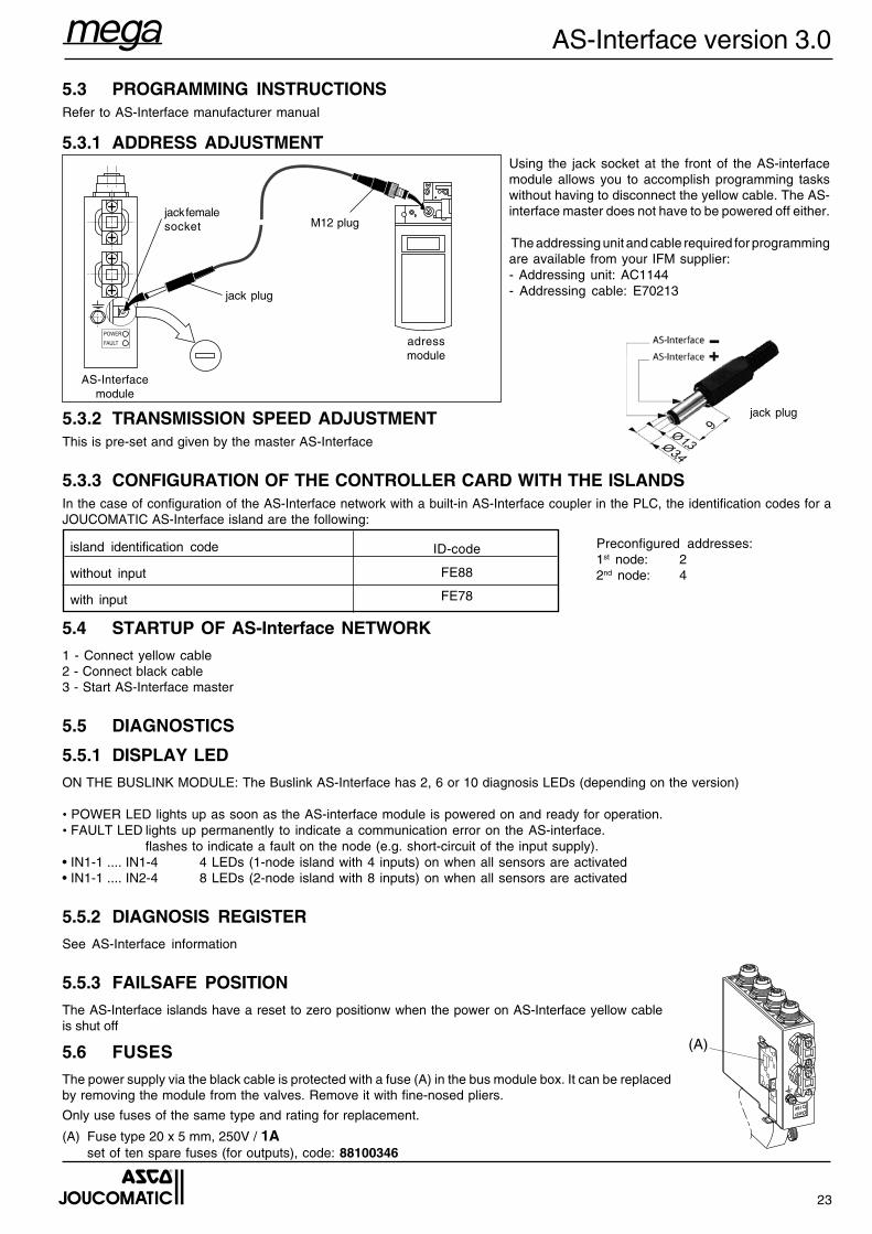
5.4 STARTUP OF AS-Interface NETWORK1 - Connect yellow cable2 - Connect black cable3 - Start AS-Interface master
5.5 DIAGNOSTICS
5.5.1 DISPLAY LEDON THE BUSLINK MODULE: The Buslink AS-Interface has 2, 6 or 10 diagnosis LEDs (depending on the version)
• POWER LED lights up as soon as the AS-interface module is powered on and ready for operation.• FAULT LED lights up permanently to indicate a communication error on the AS-interface.
flashes to indicate a fault on the node (e.g. short-circuit of the input supply).• IN1-1 .... IN1-4 4 LEDs (1-node island with 4 inputs) on when all sensors are activated• IN1-1 .... IN2-4 8 LEDs (2-node island with 8 inputs) on when all sensors are activated
5.5.2 DIAGNOSIS REGISTERSee AS-Interface information
5.5.3 FAILSAFE POSITIONThe AS-Interface islands have a reset to zero positionw when the power on AS-Interface yellow cableis shut off
5.6 FUSESThe power supply via the black cable is protected with a fuse (A) in the bus module box. It can be replacedby removing the module from the valves. Remove it with fine-nosed pliers.
Only use fuses of the same type and rating for replacement.
(A) Fuse type 20 x 5 mm, 250V / 1Aset of ten spare fuses (for outputs), code: 88100346
(A)
5.3 PROGRAMMING INSTRUCTIONSRefer to AS-Interface manufacturer manual
5.3.1 ADDRESS ADJUSTMENT
5.3.2 TRANSMISSION SPEED ADJUSTMENTThis is pre-set and given by the master AS-Interface
5.3.3 CONFIGURATION OF THE CONTROLLER CARD WITH THE ISLANDSIn the case of configuration of the AS-Interface network with a built-in AS-Interface coupler in the PLC, the identification codes for aJOUCOMATIC AS-Interface island are the following:
jack femalesocket
Using the jack socket at the front of the AS-interfacemodule allows you to accomplish programming taskswithout having to disconnect the yellow cable. The AS-interface master does not have to be powered off either.
The addressing unit and cable required for programmingare available from your IFM supplier:- Addressing unit: AC1144- Addressing cable: E70213
adressmodule
POWERFAULT
jack plug
M12 plug
island identification code
without input
with input
ID-code
FE88
FE78
Preconfigured addresses:1st node: 22nd node: 4
AS-Interfacemodule
jack plug
24
AS-Interface version 3.0
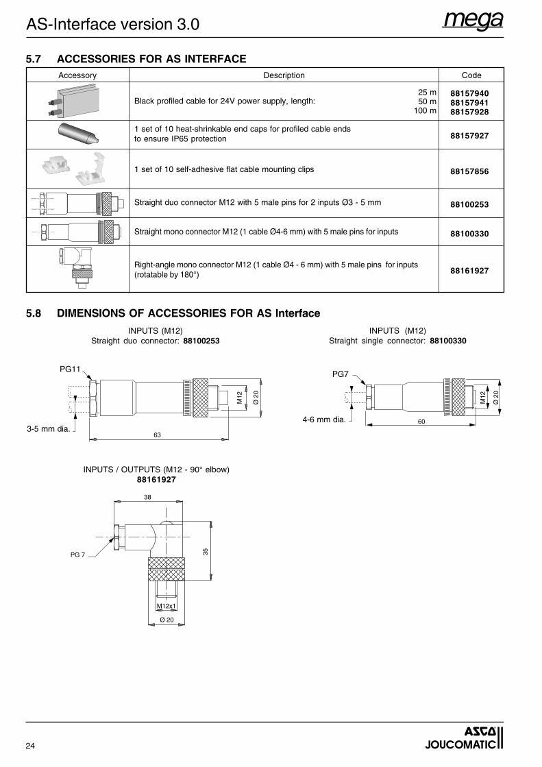
5.7 ACCESSORIES FOR AS INTERFACE
5.8 DIMENSIONS OF ACCESSORIES FOR AS Interface
INPUTS (M12)Straight single connector: 88100330
INPUTS (M12)Straight duo connector: 88100253
63
M12
Ø 2
0
M12
Ø 2
0
603-5 mm dia.
PG11
4-6 mm dia.
PG7
INPUTS / OUTPUTS (M12 - 90° elbow)88161927
M12x1
Ø 20
35
38
PG 7
Black profiled cable for 24V power supply, length:
1 set of 10 heat-shrinkable end caps for profiled cable endsto ensure IP65 protection
1 set of 10 self-adhesive flat cable mounting clips
Straight duo connector M12 with 5 male pins for 2 inputs Ø3 - 5 mm
Straight mono connector M12 (1 cable Ø4-6 mm) with 5 male pins for inputs
Right-angle mono connector M12 (1 cable Ø4 - 6 mm) with 5 male pins for inputs(rotatable by 180°)
881579408815794188157928
88157927
88157856
88100253
88100330
88161927
Description Code
25 m50 m
100 m
Accessory