Embed Size (px)
Citation preview
SUMMER TRAINING REPORT
AT WELL STIMULATION SERVICES (WSS)
Oil and Natural Gas Corporation Limited, Ahmedabad
PROJECT: STIMULATION JOBS FOR
OIL AND INJECTOR WELLS
2015
MEHUL JAIN Summer trainee, ONGC, Ahmedabad asset University College of Engineering, RTU, KOTA [Type the company name]
1/12/2015
ACKNOWLEDGEMENT
The training here at Oil & Natural Gas Corporation (ONGC), WSS, Ahmedabad in Stimulation jobs has been a great experience, both educative and enjoyable at the same time. I would like to thank the entire WSS team for their support and co-operation throughout the training period 15.05.2015 to 15.07.2015.
I wish to express my indebted gratitude and special thanks to Mr. S.P.Nainwal, GGM-Head of Well Stimulation Services (WSS), Oil & Natural Gas Corporation Limited (ONGC) for giving me an opportunity to gain an insight into the working of an industry.
I would specially like to thank Mr.P.Dinesan, Sr. HR Executive for allowing me to do my project here at WSS.
I express my deepest thanks to my guide Mr. K.W.S Rajendra (GM, Location Manager WSS) And Mr. S.K. Singh (DGM, Production) for his vital encouragement and guidance to carry out my industrial training work at WELL STIMULATION SERVICES.
I would like to thank Mr. Suyog Yadav (Asst. Executive Engineer) For his guidance throughout the training period.
Mehul Jain
Student of B.Tech. (Petroleum)
University College of Engineering,
Rajasthan Technical University, Kota
Trainee
Comp: Oil & Natural Gas Corporation Limited
Ahmedabad
Well Stimulation Services
Oil and Natural Gas Corporation Limited
Ahmedabad Asset
Certificate
This is to certify that Mr. Mehul Jain from University College of Engineering,
RTU, Kota has successfully completed his project work on ‘Well Stimulation
Jobs for Oil and Injector Wells’ at the Well Stimulation Services (WSS),
ONGC, Ahmedabad as a part of his Curriculum. The Project was carried out
from 1st June 2015 to 15th July 2015.
The project is a part of the fulfillment of the B.Tech. degree in Petroleum
Engineering from University College of Engineering , RTU, Kota.
Mr. Suyog Yadav Mr. S.K. Singh
(Asst. Executive Engineer) DGM- Production
Project Coordinator Project Guide
INDEX
Sr. No. Contents
1. Overview of Well Stimulation Services in ONGC
2. Introduction to Well Stimulation
3. Hydraulic Fracturing
4. Acidization
5. Coiled tubing Services
6. Nitrogen Services
7. Sand Control Services
8. Hot Oil Services
9. Case Study
OVERVIEW OF WELL STIMULATION
SERVICES ONGC
Well Stimulation Services in ONGC started with the creation of central
stimulation team (CST) in year 1975 to cater the stimulation needs of western
region.
The CST was transformed into Well Stimulation Services (WSS), Ahmedabad in
1982.
ONGC entered into a technical collaboration with NOWSCOW, Canada for
transfer of state of the art equipment and technology that were required for
well stimulation.
After the base at Ahmedabad other Well Stimulation Service bases were
subsequently created to cater the needs of different regions.
The Ahmedabad base was made the mother base and the other bases were
developed under its guidance. ONGC now has bases at:
Ahmedabad(1982,mother base)
Sivsagar(1982)
Rajahmundry(1982)
Karikal(1990)
Gandhar(1995)
Bokaro(2001)
Jorhat(2004)
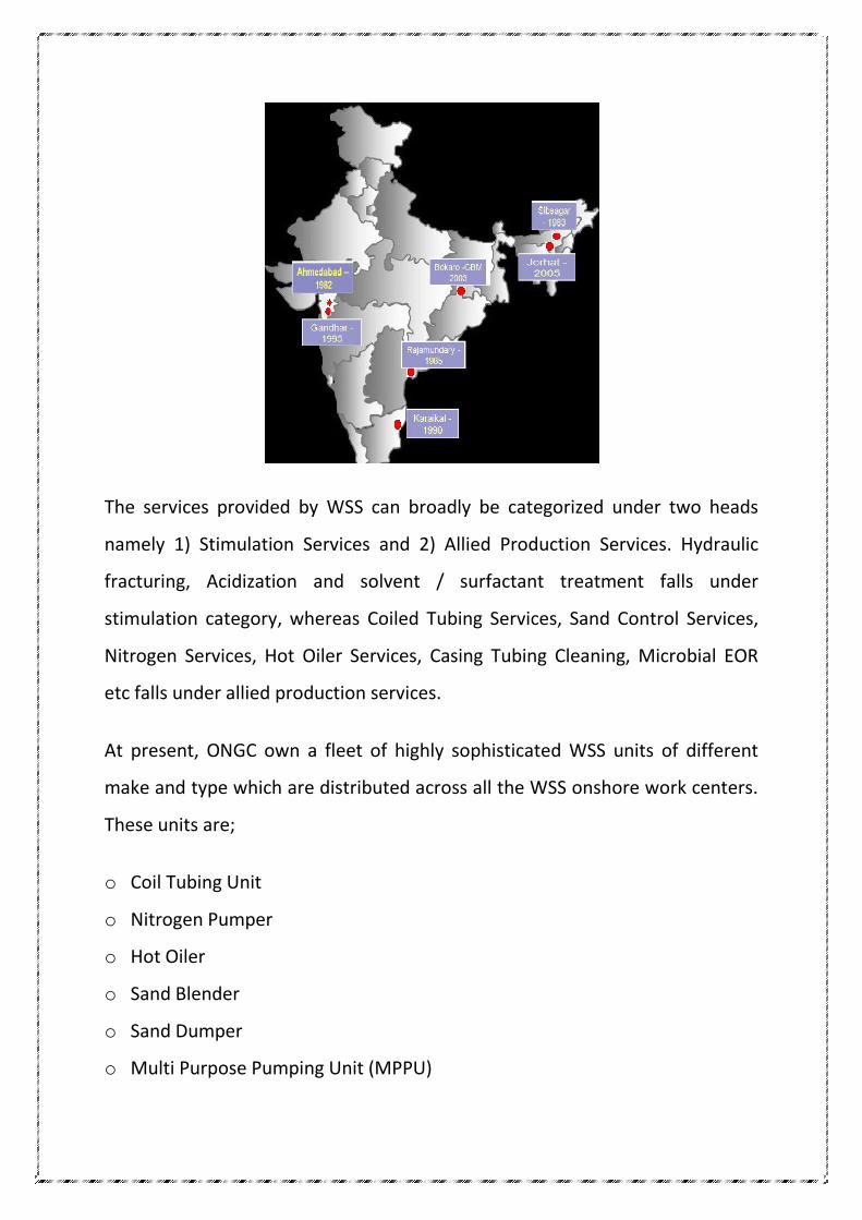
The services provided by WSS can broadly be categorized under two heads
namely 1) Stimulation Services and 2) Allied Production Services. Hydraulic
fracturing, Acidization and solvent / surfactant treatment falls under
stimulation category, whereas Coiled Tubing Services, Sand Control Services,
Nitrogen Services, Hot Oiler Services, Casing Tubing Cleaning, Microbial EOR
etc falls under allied production services.
At present, ONGC own a fleet of highly sophisticated WSS units of different
make and type which are distributed across all the WSS onshore work centers.
These units are;
o Coil Tubing Unit
o Nitrogen Pumper
o Hot Oiler
o Sand Blender
o Sand Dumper
o Multi Purpose Pumping Unit (MPPU)
o Frac Pumper
o Acid Pumper
o Acid Tanker
WSS AHMEDABAD
WSS Ahmedabad was established in 1982, it has expertise in carrying out
different types of stimulation jobs. The head office of WSS Ahmedabad is
located at Chandkheda, Ahmedabad which houses the offices of Head WSS, IN
charge HR-ER, IN charge TSG, IN charge Material Management, IN charge
finance and IN charge procurement and contracts. It has two bases located at
Saij and Sertha. The Saij base takes care of Hydraulic fracturing, Hot oil
circulation and Acidization jobs. It also houses the Maintenance section and
the Chemistry lab, while Sertha base is involved in carrying out Coiled tubing
applications, Nitrogen jobs and Sand control jobs.
WSS Ahmedabad caters to the needs of both Ahmedabad asset and
Mehsana asset it also provides services to Mumbai offshore as and when
required apart from this it also provide support to other bases for special jobs.
The services rendered and capabilities of WSS Ahmedabad are as follows:
1. Hydraulic fracturing
Pumping horse power 9000 HP
Pumping pressure 12000 psi
Pumping rate 60 BPM
Design by 3D FracPro simulator
Experience of more than 1700 jobs
First ever FracPack job in India
2. Acidization
Acid storage capacity 50m3
Pumping pressure 10,000psi
Job design using MACIDES
Experience of more than 5000 jobs
Development of customized acid formulation for sand stone reservoirs
Deep penetrating acid system
Retarded mud acid system
Reduced strength mud acid
Emulsified acid system
Chemical diversion system
Alcoholic mud acid system
Nitrified acid system
3. Coiled tubing applications
Coiled tubing size :1 1/4 ̓ ̓, 1 1/2 ̓ ̓
Depth: 5000 meters
Injector capacity up to 80,000lbs
Online monitoring of tubing fatigue
Experience of more than 7000 jobs
CTU operations carried out by WSS Ahmedabad
Well Bore Clean Outs
Zone Isolation for Water Control
Well Stimulation
Well Activation
Velocity String Completion
Well Intervention In Horizontal/High Angle/Multilateral Wells
Well Subduing And Fishing
Well Plug And Abandonment
Cement Drilling
Dewaxing
4. Sand control
Job design and execution of different sand control techniques
GP for 5 1/2 ̓ ̓ and 7 ̓ ̓ casing
High rate water pack
Pre pack completion
Fracpack
High density slurry packing
Experience of more than 1400 jobs
First gravel packing of horizontal well
Longest gravel pack (>200mts)
First ever fracpack
5. Nitrogen services
Liquid nitrogen storage capacity :100 m3
Pumping rate : 8.5-170 m3/min
Pumping pressure : 10,000psi
Experience of more than 17000 jobs
Nitrogen applications
Well fluid displacement
Nitrification of fluids for acidization
Foam cleanout in sub-hydrostatic wells
Pressure testing/purging of gas plant,pipe lines and equipment
Foam fracturing
6. Hot oil circulation
Ciculation fluid temperature: 90 ͦ c
Pumping rate : 140 lpm
Heat transfer : 7MMBTU/Hr
Experience of more than 4500 HOC jobs
7. Laboratory services
o Equipments
High temperature, high pressure viscometer
Core flow setup
Sieve analyser
Corrosion test apparatus
API crush test machine
o Chemical formulation for specific field requirements
Hydraulic fracturing
Acidiztion
o Development for field application
High temperature frac fluid
Breaker for low temperature reservoir
8. Maintenance services
o Workshop facilities
Preventive maintenance
Breakdown maintenance
Capital overhauling
Under chassis repair
o Expertise in
Transmission system
Engine
Hydraulic systems
Instrumentation
Pump and compressor
Heat exchengers
o Equipment population
60 primemovers cummins/Detroit/caterpillar
60 transmission Allison and fuller
20 reciprocating pump OPI and SPM
35 centrifugal pumps
250 hydraulic pumps and motors
5 cranes
6 heat exchangers
INTRODUCTION TO STIMULATION
History:-
Stimulation can be traced to the 1860s, when liquid (and later, solidified)
nitroglycerin (NG) was used to stimulate shallow, hard rock wells in
Pennsylvania, New York, Kentucky, and West Virginia. Although extremely
hazardous, and often used illegally, NG was spectacularly successful for oil well
“shooting.” The object of shooting a well was to break up, or rubblize, the oil-
bearing formation to increase both initial flow and ultimate recovery of oil.
This same fracturing principle was soon applied with equal effectiveness to
water and gas wells.
In the 1930s, the idea of injecting a nonexplosive fluid (acid) into the ground
stimulate a well began to be tried. The “pressure parting” phenomenon was
recognized in well-acidizing operations as a means of creating a fracture that
would not close completely because of acid etching. This would leave a flow
channel to the well and enhance productivity. The phenomenon was
confirmed in the field, not only with acid treatments, but also during water
injection and squeeze cementing operations. But it was not until Floyd Farris of
Stanolind Oil and Gas Corporation (Amoco) performed an in-depth study to
establish a relationship between observed well performance and treatment
pressures that “formation breakdown” during acidizing, water injection, and
squeeze cementing became better understood. From this work, Farris
conceived the idea of hydraulically fracturing a formation to enhance
production from oil and gas wells.
The first experimental treatment to “Hydrafrac” a well for stimulation was
performed in the Hugoton gas field in Grant County, Kansas, in 1947 by
Stanolind Oil. A total of 1,000 gal of naphthenic-acid and- palm-oil- (napalm-)
thickened gasoline was injected, followed by a gel breaker, to stimulate a gas
producing limestone formation at 2,400 ft. Deliverability of the well did not
change appreciably, but it was a start. In 1948, the Hydrafrac process was
introduced more widely to the industry in a paper written by J.B. Clark of
Stanolind Oil. A patent was issued in 1949, with an exclusive license granted to
the Halliburton Oil Well Cementing Company (Howco) to pump the new
Hydrafrac process.
What is stimulation?
Oil well stimulation is the general term describing a variety of operations
performed on a well to improve its productivity. Stimulation operations can be
focused solely on the wellbore or on the reservoir; it can be conducted on old
wells and new wells alike; and it can be designed for remedial purposes or for
enhanced production. Its main two types of operations are matrix acidization
and hydraulic fracturing. Matrix acidization involves the placement of acid
within the wellbore at rates and pressures designed to attack an impediment
to production without fracturing or damaging the reservoir (typically,
hydrofluoric acid is used for sandstone/silica-based problems, and hydrochloric
acid or acetic acid is used for limestone/carbonate-based problems). Most
matrix stimulation operations target up to a ten foot radius in the reservoir
surrounding the wellbore. Hydraulic fracturing, which includes acid fracturing,
involves the injection of a variety of fluids and other materials into the well at
rates that actually cause the cracking or fracturing of the reservoir formation.
The variety of materials includes, amongst others: water, acid, special polymer
gels, and sand. The fracturing of the reservoir rock and the subsequent filling
of the fractured voids with sand ("proppant") or the creation of acid channels
allows for an enhanced conduit to the wellbore from distances in excess of a
hundred feet.
Why is stimulation required?
Hydraulic fracturing and acid fracturing in practically all types of formations
and oil gravities, when done correctly, have been shown to increase well
productivity above that projected in both new and old wells. From an economic
standpoint, oil produced today is more valuable than oil produced in the future.
Fracturing candidates may not necessarily "need" oil well stimulation, but the
economics may show that such a treatment would payoff.
To understand why remedial stimulation (matrix acidization) is necessary, one
has to consider the conditions at work, deep down inside the reservoir. Before
the well is ever drilled, the untapped hydrocarbons sit in the uppermost portions
of the reservoir (atop any present water) inside the tiny pore spaces, and in
equilibrium at pressures and temperatures considerably different from surface
conditions. Once penetrated by a well, the original equilibrium condition
(pressure, temperature, and chemistry) is permanently changed with the
introduction of water or oil-based drilling fluids loaded with suspended clays,
and the circulation of cement slurries. The interaction of the introduced fluids
with those originally present within the reservoir, coupled with pressure and
temperature changes can cause a variety of effects which, in turn, can plug the
numerous odd-shaped pores causing formation damage. Some of the types of
damage include: scale formation, clay swelling, fines migration, and organic
deposition.
Petroleum engineers refer to the level of formation damage around the wellbore
as skin effect. A numerical value is used to relate the level of formation damage.
A positive skin factor reflects damage/impedance to normal well productivity,
while a negative value reflects productivity enhancement. Formation damage,
however, is not limited to initial production operations. Remedial operations of
all kinds from well killing to well stimulation itself, can cause formation
damage. Nor is fines and scale generation limited to the reservoir. They can also
develop in the wellbore in casing and tubulars, and be introduced from surface
flowlines and incompatible injection fluids. These fines and precipitates can
plug pores and pipe throughout an entire oil field.In short, any operation
throughout a well's life can cause formation damage and impede productivity.
Hydraulic Fracturing
What is fracturing?
If fluid is pumped into a well faster than the fluid can escape into the formation,
inevitably pressure rises, and at some point something breaks. Because rock is
generally weaker than steel, what breaks is usually the formation, resulting in
the wellbore splitting along its axis as a result of tensile hoop stresses generated
by the internal pressure. the simple idea of the wellbore splitting like a pipe
becomes more complex for cased and/or perforated wells and nonvertical wells.
However, in general, the wellbore breaks—i.e., the rock fractures—owing to the
action of the hydraulic fluid pressure, and a “hydraulic” fracture is created.
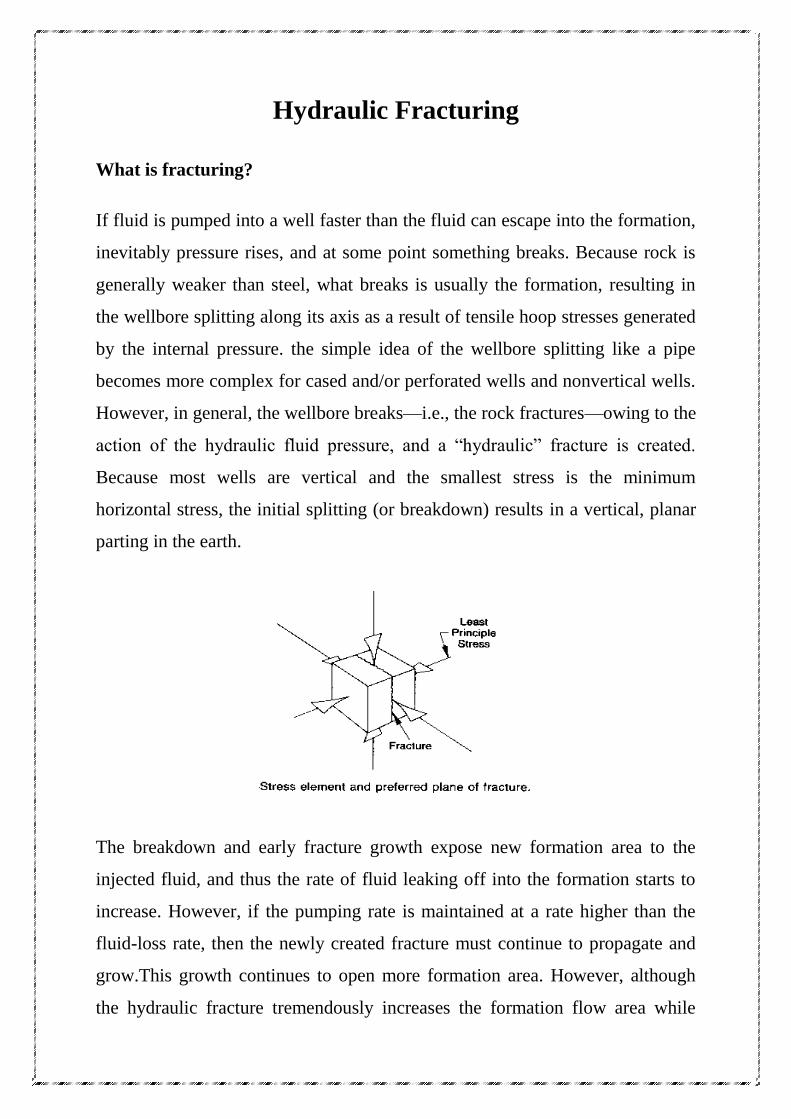
Because most wells are vertical and the smallest stress is the minimum
horizontal stress, the initial splitting (or breakdown) results in a vertical, planar
parting in the earth.
The breakdown and early fracture growth expose new formation area to the
injected fluid, and thus the rate of fluid leaking off into the formation starts to
increase. However, if the pumping rate is maintained at a rate higher than the
fluid-loss rate, then the newly created fracture must continue to propagate and
grow.This growth continues to open more formation area. However, although
the hydraulic fracture tremendously increases the formation flow area while
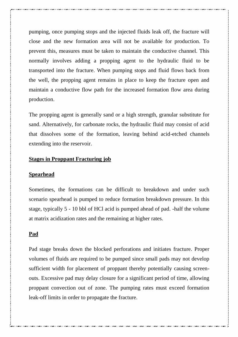
pumping, once pumping stops and the injected fluids leak off, the fracture will
close and the new formation area will not be available for production. To
prevent this, measures must be taken to maintain the conductive channel. This
normally involves adding a propping agent to the hydraulic fluid to be
transported into the fracture. When pumping stops and fluid flows back from
the well, the propping agent remains in place to keep the fracture open and
maintain a conductive flow path for the increased formation flow area during
production.
The propping agent is generally sand or a high strength, granular substitute for
sand. Alternatively, for carbonate rocks, the hydraulic fluid may consist of acid
that dissolves some of the formation, leaving behind acid-etched channels
extending into the reservoir.
Stages in Proppant Fracturing job
Spearhead
Sometimes, the formations can be difficult to breakdown and under such
scenario spearhead is pumped to reduce formation breakdown pressure. In this
stage, typically 5 - 10 bbl of HCl acid is pumped ahead of pad. -half the volume
at matrix acidization rates and the remaining at higher rates.
Pad
Pad stage breaks down the blocked perforations and initiates fracture. Proper
volumes of fluids are required to be pumped since small pads may not develop
sufficient width for placement of proppant thereby potentially causing screen-
outs. Excessive pad may delay closure for a significant period of time, allowing
proppant convection out of zone. The pumping rates must exceed formation
leak-off limits in order to propagate the fracture.
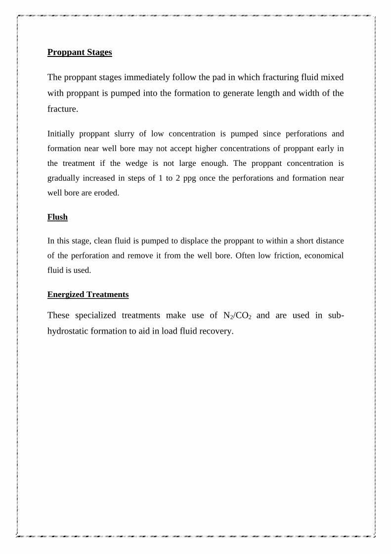
Proppant Stages
The proppant stages immediately follow the pad in which fracturing fluid mixed
with proppant is pumped into the formation to generate length and width of the
fracture.
Initially proppant slurry of low concentration is pumped since perforations and
formation near well bore may not accept higher concentrations of proppant early in
the treatment if the wedge is not large enough. The proppant concentration is
gradually increased in steps of 1 to 2 ppg once the perforations and formation near
well bore are eroded.
Flush
In this stage, clean fluid is pumped to displace the proppant to within a short distance
of the perforation and remove it from the well bore. Often low friction, economical
fluid is used.
Energized Treatments
These specialized treatments make use of N2/CO2 and are used in sub-
hydrostatic formation to aid in load fluid recovery.
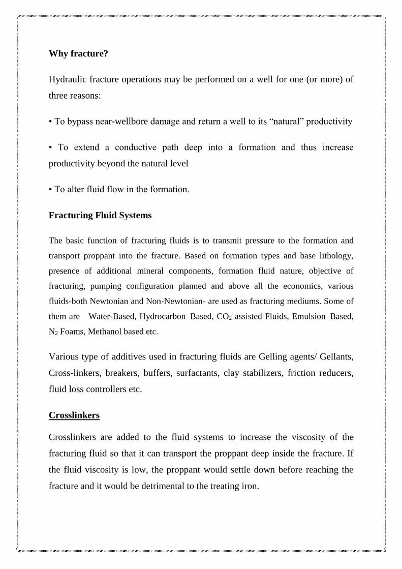
Why fracture?
Hydraulic fracture operations may be performed on a well for one (or more) of
three reasons:
• To bypass near-wellbore damage and return a well to its “natural” productivity
• To extend a conductive path deep into a formation and thus increase
productivity beyond the natural level
• To alter fluid flow in the formation.
Fracturing Fluid Systems
The basic function of fracturing fluids is to transmit pressure to the formation and
transport proppant into the fracture. Based on formation types and base lithology,
presence of additional mineral components, formation fluid nature, objective of
fracturing, pumping configuration planned and above all the economics, various
fluids-both Newtonian and Non-Newtonian- are used as fracturing mediums. Some of
them are Water-Based, Hydrocarbon–Based, CO2 assisted Fluids, Emulsion–Based,
N2 Foams, Methanol based etc.
Various type of additives used in fracturing fluids are Gelling agents/ Gellants,
Cross-linkers, breakers, buffers, surfactants, clay stabilizers, friction reducers,
fluid loss controllers etc.
Crosslinkers
Crosslinkers are added to the fluid systems to increase the viscosity of the
fracturing fluid so that it can transport the proppant deep inside the fracture. If
the fluid viscosity is low, the proppant would settle down before reaching the
fracture and it would be detrimental to the treating iron.
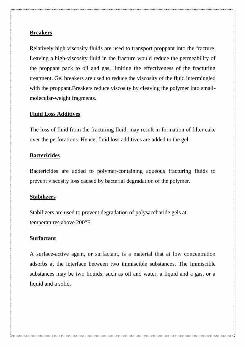
Breakers
Relatively high viscosity fluids are used to transport proppant into the fracture.
Leaving a high-viscosity fluid in the fracture would reduce the permeability of
the proppant pack to oil and gas, limiting the effectiveness of the fracturing
treatment. Gel breakers are used to reduce the viscosity of the fluid intermingled
with the proppant.Breakers reduce viscosity by cleaving the polymer into small-
molecular-weight fragments.
Fluid Loss Additives
The loss of fluid from the fracturing fluid, may result in formation of filter cake
over the perforations. Hence, fluid loss additives are added to the gel.
Bactericides
Bactericides are added to polymer-containing aqueous fracturing fluids to
prevent viscosity loss caused by bacterial degradation of the polymer.
Stabilizers
Stabilizers are used to prevent degradation of polysaccharide gels at
temperatures above 200°F.
Surfactant
A surface-active agent, or surfactant, is a material that at low concentration
adsorbs at the interface between two immiscible substances. The immiscible
substances may be two liquids, such as oil and water, a liquid and a gas, or a
liquid and a solid.
Clay Stabilizers
Clay Stabilizers are used to prevent the swelling of clays encountered while
fracturing the formation.
Proppant
Proppants are used to hold the walls of the fracture apart to create a conductive
path to the wellbore after pumping has stopped and the fracturing fluid has
leaked off. Placing the appropriate concentration and type of proppant in the
fracture is critical to the success of a hydraulic fracturing treatment. Factors
affecting the fracture conductivity (a measurement of how a propped fracture is
able to convey the produced fluids over the producing life of the well) are
proppant composition
physical properties of the proppant
proppant-pack permeability
effects of postclosure polymer concentration in the fracture
movement of formation fines in the fracture
long-term degradation of the proppant.
ACIDIZATION
Acid may be used to reduce specific types of damage near the wellbore in all
types of formations. Inorganic, organic, and combinations of these acids, along
with surfactants, are used in a variety of well stimulation treatments. In
carbonate formations, acid may be used to create linear flow systems by etching
hydraulically created fractures. Acid fracturing is not applicable to sandstone
formations.
The two basic types of acidizing are characterized through injection rates and
pressure. Injection rates below fracture pressure are termed matrix acidizing,
while those above fracture pressure are termed as fracture acidizing.
MATRIX ACIDIZATION :-
Matrix stimulation is a technique that has been used extensively since the 1930s
to improve production from oil and gas wells and to improve injection into
injection wells. Matrix stimulation is accomplished by injecting a fluid (e.g.,
acid or solvent) to dissolve and/or disperse materials that impair well production
in sandstones or to create new, unimpaired flow channels between the wellbore
and a carbonate formation. In matrix stimulation, fluids are injected below the
fracturing pressure of the formation (McLeod, 1984). It is estimated that matrix
treatments constitute 75% to 80% of all stimulation treatments (matrix and
fracturing) worldwide, but the total expenditure for matrix treatments is only
20% to 25% of the total for all stimulation treatments. However, because the
payout time for matrix treatments is normally days rather than months as it is
for conventional fracturing treatments. Many operators around the world have
indicated that an average of 40% to 50% of their wells have significant damage,
but routinely only 1% to 2% of their wells are treated every year. Substantial
production improvements can be achieved with matrix stimulation if treatments
are engineered properly. A success rate greater than 90% is reasonable.
Acidization is a technique of injecting acid and chemicals in the reservoir to reduce
damage near the well bore for improving well productivity/ injectivity. Inorganic,
organic and combination of these acids along with surfactants are used in variety of
well stimulation treatments. The two basic types of acidizing are characterized
through injection rate and pressures. Injection rates below fracture pressure are termed
matrix acidizing while those above fracture pressure are termed as fracture acidizing.
Matrix acidizing is primarily applied to remove near well bore damage caused
by drilling/ completion/ workover fluids. or injection fluids and by precipitation
of scale deposits from produced or injected water. The goal of matrix acidizing
is to achieve radial acid penetration in to the formation for removal of effects of
permeability reduction near well bore. The objective of an acid treatment is to
react with the formation rock and / or pore plugging materials to form suitable
salts that can be produced to the surface, or displaced into the pore system some
distance away from the well bore - thus providing enlarged or more open flow
channels.
Basic acids used in various combinations are Hydrochloric Acid, Hydrochloric
+ Hydrofluoric Acid, Formic Acid and to lesser extent Fluoboric Acid and
Sulfamic Acid. Typically, 15 % HCl acid for carbonate reservoirs and 12 %
HCl & 3 % HF acid for sandstone reservoirs is used in wells.
Acid Additives :-
Acidizing can be the cause of a number of well problems. Acid may release
fines, create precipitants, form emulsions, create sludge and corrode steel.
Additives are available to correct these and number of other problems. Each
acid additive used serves a specific purpose. However, where several additives
are used they must be carefully checked under simulated treatment conditions to
ensure that one additive does not react with another. Some of the commonly
used additives are.
Corrosion Inhibitor
Corrosion inhibitors are used to prevent metallic corrosion from occurring and
work through creation of a protective layer on the metallic surface. Factors that
govern acid attack on steel are; steel type and hardness, temperature, acid type,
acid concentration and acid contact time.
Surfactant
Surfactants are used to change surface and interfacial tensions, prevent emulsions,and
water-wet rockand fines near the well bore. The use of surfactants in acid assists in
faster flow back of spent acid after acid treatment thereby improving the chances of
early well activation.
Non-Emulsifier
The non-emulsifier contains water-soluble polymer that is temperature sensitive
that helps to lower surface tension and prevent damage.
Anti Sludge Agent
“Sludge” is a precipitate resulting from reaction of high strength acid with
crude. The sludge formation can hamper cleaning of the well and flow
performance
Iron Controller
In order to prevent precipitation of iron, iron controllers are used in the acid that
control iron precipitation either through chelating (iron chemically bound) or
sequestering (iron held in solution).
Mutual Solvent
The mutual solvent is used to reduce water saturation near the well bore, maintain a
water wet formation, water wet insoluble formation fines and help reduce the
absorption of surfactants and inhibitors on the formation
Diverting Agent
The diverting agent plays a major role in selective acidization of a particular
layer. The diverting agent blocks the permeable layer and allows the acid to
enter the intended zone and get stimulated.
Clay Stabilizer
Certain clay compounds can be treated with acid but result in undesirable
reactions during acidization like swelling and creation of water blocks that
hamper the stimulation job efficiency. Clay stabilizers are used to keep the clays
and fines in suspension.
Fluid Loss Control Agents
Helps in extending fractures in fracture acidizing by reducing acid leak off into
the formation.
STEPS INVOLVED IN ACIDIZATION
The primarily acidization treatment involves following three stages:
• Pre-flush Stage
In this stage, 5 to 10 % HCl acid is pumped in to formation to remove the
carbonates and also to push NaCl and KCl away from the well bore. The volume
of pre-flush pumped depends on thickness of the layer to be treated but in general
50 to 100 gal/ft of the formation is the norm.
• Acid Stage
This forms the main stage in the acidization. Requisite volume of HCl acid
is pumped into the formation to dissolve the carbonates and create paths /
vugs to connect reservoir with well bore. HF acid is used in the case of
sandstone reservoirs to dissolve clay and sand.
• After-flush stage (10% EGMBE)
Subsequent to acid stage, 10 % EGMBE is pumped as after flush to make
the formation water wet and to displace acid away from the well bore.
Pump entire treatment at low rate, 0.25 to 0.5 bbl/min below frac pressure.
As HCL and HF spend very rapidly, start removing the spent acid from
around the wellbore within about one hour after treatment is completed. In
flowing wells, initially flow back should be at low rate and gradually
increasing over a reasonable time. In non flowing wells some means of
initiating flow, i.e. swabbing or gas lifting will be required. It is not always
necessary to swab water and gas injection wells following an acid job.
Within one hour after treatment, regular injection in water or gas injection
wells may be resumed.
SET UP FOR ACIDIZATION JOB :-
The acidization set-up typically consists of :
a) Acid tanker of 12m3 volume for transportation of 30 % HCl acid from
WSS base to well site.
b) Acid Pumping Unit (APU) equipped with acid mixing tank to prepare
acid of requisite composition and concentration, pumping system
complete with metering and controls.
c) Syphon assembly to safely transfer acid from acid tanker to acid mixing
tank.
d) Flexible steel pipe / coflex hose to carry acid from pumping unit in to the
well.
COILED TUBING SERVICES
Coiled Tubing :-
In the oil and gas industries, coiled tubing refers to metal piping, normally 1" to
3.25" in diameter, used for interventions in oil and gas wells and sometimes as
production tubing in depleted gas wells, which comes spooled on a large reel.
Coiled tubing is often used to carry out operations similar to wirelining. The
main benefits over wireline are the ability to pump chemicals through the coil
and the ability to push it into the hole rather than relying on gravity. However,
for offshore operations, the 'footprint' for a coiled tubing operation is generally
larger than a wireline spread, which can limit the number of installations
where coiled tubing can be performed and make the operation more costly.
coiled tubing units are second generation of workover rig with hydraulic
system for well servicing under pressure. The Coiled Tubing Unit (CTU) has
endless tubing stored on a reel and run into hole (RIH) or pulled out of hole
(POOH) by means of continuous motion friction device (Injector assembly).
Well servicing using coiled tubing has grown significantly with the
development of tooling and tubing technology. The size of tubing available
vary from 1 inch through 4 ½” inch (in ONGC, 1 ¼” and 1 ½” size is normally
used). The material of tubing has improved tremendously to give higher
performance. Much of the recent increase in capability is due to the increased
performance of downhole motors, which provided the ability to rotate,
enabling drilling and milling operations etc.
CT APPLICATIONS :-
The Coiled Tubing Unit (CTU) is used for various well servicing jobs. Some of the
applications are as listed here under:
CONVENTIONAL CT APPLICATIONS
Jetting for bottom/ screen clean out.
Activation for production
Paraffin removal
Stimulation
Tubing clean out
Emergency well control
ADVANCED CT APPLICATIONS
Through-tubing operations like fishing, packer setting, zone isolation etc.
Cementation and water shut off
Running, setting, pulling wireline pressure operated type tools.
Selective zonal acidizing
SPECIALIZED CT APPLICATIONS
Logging and perforations
Cleaning of flow lines
Servicing of horizontal wells
STIMULATION JOBS THROUGH CT
1. The stimulation jobs, mainly acid applications and nitrogen placement,
are carried out through CT especially when annulus is packed off. Stimulation
jobs through CT not only save the time but provide efficient and accurate
placement of acid, easier & faster removal of spent acid and provides
continuous well control. However, acid job through CT has working pressure
limitation and affect the CT life considerably.
2. The use of CT in high-pressure wells requires additional considerations
with regard to pressure control equipment, burst & collapse rating of the CT,
capability of injector head to push the CT against high wellhead pressures and
possibility of CT buckling. During CT operation in high-pressure wells, the
collapse of CT can be avoided by using smaller diameter, heavy walled CT and
maintaining pressure inside CT. In addition, the CT is run without check valves
to prevent emptying of the string.
DESCRIPTION OF COIL TUBING SYSTEM
The CT system comprises of following equipment;
A. Operator’s Control Cabin
B. Tubing reel
C. Injector head
D. Pressure Control Equipment
E. Power pack
F. Goose neck
G. Stripper
H. BOP system
A. Operator’s Control Cabin
The control cabin houses all the controls for the reel, the injector head, and
also all electronic logging systems and instrumentation. It is placed directly
behind the reel to provide the operator with a full view of all activities
especially the spooling of the tubing off and on the reel, the well head &
injector.
The control console continuously monitors the operational parameters of
various components of the CT system. It houses the controls relevant to the
operation including the main hydraulic control panel (to control the
injector, reel and spooler system), well control package (stuffing box,
emergency BOP functions), main recording instrumentation and depth
correlation.
B. Tubing Reel
Tubing reel stores the tubing which is coiled around the core of the reel.
Ideally the core should be as large a diameter as possible to prevent severe
bending of the tubing but must be of a manageable size for transporting to
and from well sites.
The major components of CT reel include reel drum, reel drive system, level
wind assembly, reel swivel and manifold as shown in figure 2.1. The reel is
driven by chain from a hydraulic motor and is controlled from the control
cabin. The tubing is pulled off the reel up over the gooseneck by the
injector.
C. Injector Head
The injector allows the CT to run in or out of the well. Major injector-head
components include hydraulic motors, drive chains, chain tensioners,
gooseneck or guide-arch and weight indicator.
The injector is the motive device, which imparts upward or downward
movement to the tubing and is mounted above the BOPs on the wellhead.
It must be supported, as the connection to the BOPs is not designed to
absorb the weight and lateral forces caused by the tension in the tubing
from the reel.
Movement is imparted to the tubing by sets of travelling chains equipped
with gripper blocks, which are hydraulically driven.
The gripper blocks grip by friction which is adjustable through a hydraulic
piston applying pressure across the chains. This pressure must be
sufficiently high enough to grip the tubing eliminating slippage but not
excessively high enough to crimp the tubing.
D. Pressure Control Equipment
The pressure control equipment consists of stuffing box, stripper elements
and BOP of various designs depending on a particular application.
The stripper is designed to provide a pressure-tight seal or pack-off around
the coil tubing as it is being run in or pulled out of a well under pressure
conditions.
This seal is achieved by energizing the stripper packer that forces the inserts
to seal against the tubing.
The BOP consists of blind rams, shear rams, slip rams, pipe rams, equalizing
valves, top and bottom connections etc. The BOP rams are hydraulically
operated from the control cabin using the BOP hydraulic circuit and
accumulator. The accumulator provides a reserve of hydraulic energy to
enable the BOP to be operated following an engine shutdown or circuit
failure.
E. Power pack
The power pack provides the hydraulic energy to operate the CTU functions
and controls. Generally, it consists of a diesel engine driving an array of
hydraulic pumps supplying each system or circuit with the required
pressure and flow rate. The major components of power pack include
engine, pumps, pressure control valves, hydraulic reservoir, filters &
strainers, heat exchanger and hydraulic fluid.
F. Goose Neck
The gooseneck is simply a guide who accepts the tubing coming from the
reel and leads it into the injector chains in the vertical plane. The goose
neck guides the pipe using sets of rollers in a frame spaced on the
recommended radius for the tubing being run.
G. Downhole tools
Downhole tools can be categorized in to:
Primary tools such as CT connectors and check valves that are essential
for any CT operation and are hence invariably used
Support tools such as release joint and jar to enhance or support the
basic tool string functions or provide a contingency release function.
Functional tools are some special tools that are selected to perform a
particular operation such as wash over tools, jetting tools etc.
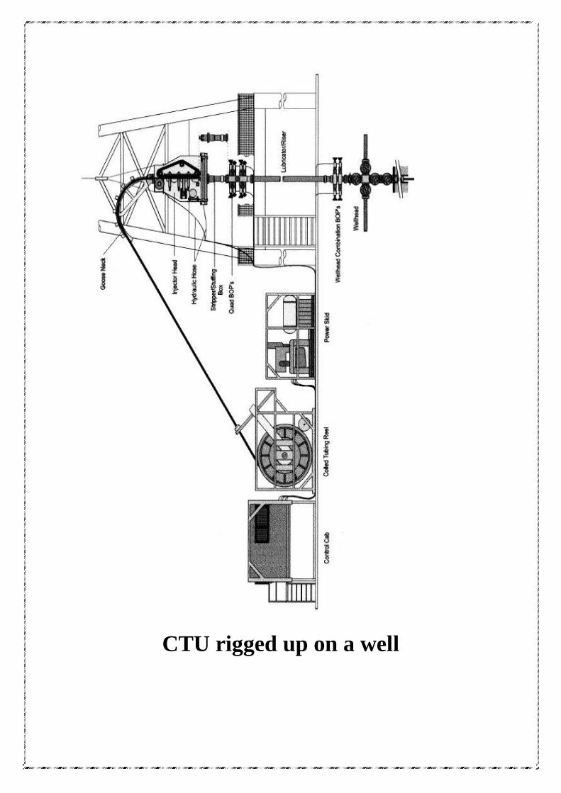
CTU rigged up on a well
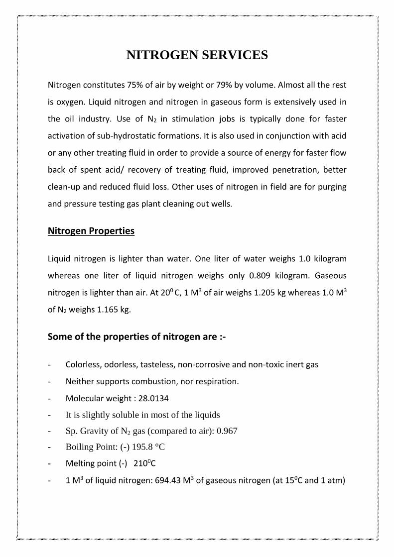
NITROGEN SERVICES
Nitrogen constitutes 75% of air by weight or 79% by volume. Almost all the rest
is oxygen. Liquid nitrogen and nitrogen in gaseous form is extensively used in
the oil industry. Use of N2 in stimulation jobs is typically done for faster
activation of sub-hydrostatic formations. It is also used in conjunction with acid
or any other treating fluid in order to provide a source of energy for faster flow
back of spent acid/ recovery of treating fluid, improved penetration, better
clean-up and reduced fluid loss. Other uses of nitrogen in field are for purging
and pressure testing gas plant cleaning out wells.
Nitrogen Properties
Liquid nitrogen is lighter than water. One liter of water weighs 1.0 kilogram
whereas one liter of liquid nitrogen weighs only 0.809 kilogram. Gaseous
nitrogen is lighter than air. At 200 C, 1 M3 of air weighs 1.205 kg whereas 1.0 M3
of N2 weighs 1.165 kg.
Some of the properties of nitrogen are :-
- Colorless, odorless, tasteless, non-corrosive and non-toxic inert gas
- Neither supports combustion, nor respiration.
- Molecular weight : 28.0134
- It is slightly soluble in most of the liquids
- Sp. Gravity of N2 gas (compared to air): 0.967
- Boiling Point: (-) 195.8 °C
- Melting point (-) 2100C
- 1 M3 of liquid nitrogen: 694.43 M3 of gaseous nitrogen (at 150C and 1 atm)
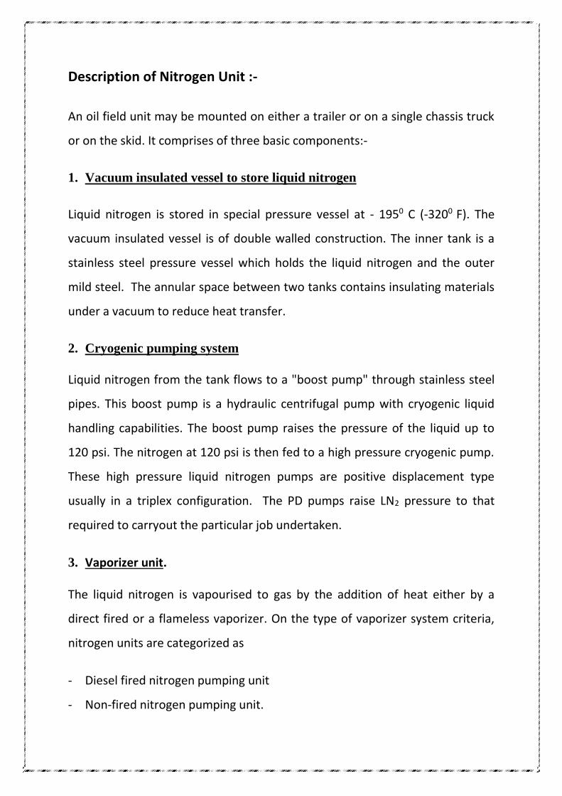
Description of Nitrogen Unit :-
An oil field unit may be mounted on either a trailer or on a single chassis truck
or on the skid. It comprises of three basic components:-
1. Vacuum insulated vessel to store liquid nitrogen
Liquid nitrogen is stored in special pressure vessel at - 1950 C (-3200 F). The
vacuum insulated vessel is of double walled construction. The inner tank is a
stainless steel pressure vessel which holds the liquid nitrogen and the outer
mild steel. The annular space between two tanks contains insulating materials
under a vacuum to reduce heat transfer.
2. Cryogenic pumping system
Liquid nitrogen from the tank flows to a "boost pump" through stainless steel
pipes. This boost pump is a hydraulic centrifugal pump with cryogenic liquid
handling capabilities. The boost pump raises the pressure of the liquid up to
120 psi. The nitrogen at 120 psi is then fed to a high pressure cryogenic pump.
These high pressure liquid nitrogen pumps are positive displacement type
usually in a triplex configuration. The PD pumps raise LN2 pressure to that
required to carryout the particular job undertaken.
3. Vaporizer unit.
The liquid nitrogen is vapourised to gas by the addition of heat either by a
direct fired or a flameless vaporizer. On the type of vaporizer system criteria,
nitrogen units are categorized as
- Diesel fired nitrogen pumping unit
- Non-fired nitrogen pumping unit.
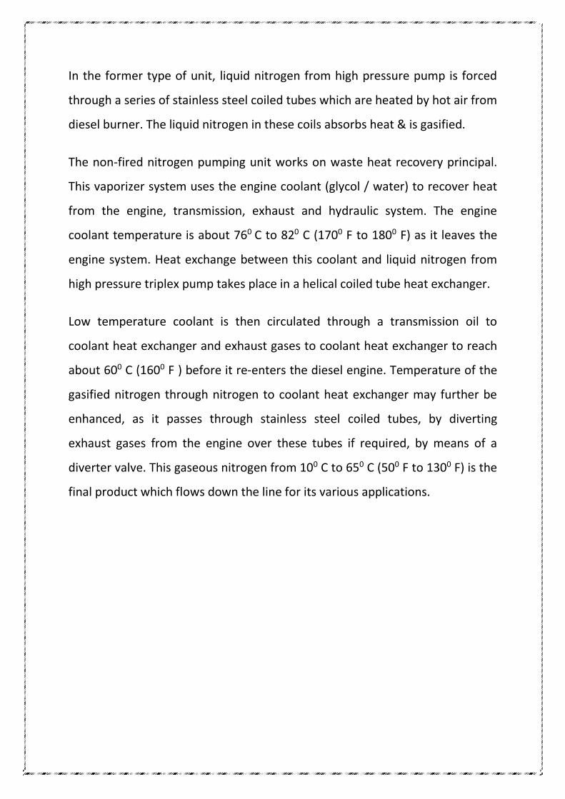
In the former type of unit, liquid nitrogen from high pressure pump is forced
through a series of stainless steel coiled tubes which are heated by hot air from
diesel burner. The liquid nitrogen in these coils absorbs heat & is gasified.
The non-fired nitrogen pumping unit works on waste heat recovery principal.
This vaporizer system uses the engine coolant (glycol / water) to recover heat
from the engine, transmission, exhaust and hydraulic system. The engine
coolant temperature is about 760 C to 820 C (1700 F to 1800 F) as it leaves the
engine system. Heat exchange between this coolant and liquid nitrogen from
high pressure triplex pump takes place in a helical coiled tube heat exchanger.
Low temperature coolant is then circulated through a transmission oil to
coolant heat exchanger and exhaust gases to coolant heat exchanger to reach
about 600 C (1600 F ) before it re-enters the diesel engine. Temperature of the
gasified nitrogen through nitrogen to coolant heat exchanger may further be
enhanced, as it passes through stainless steel coiled tubes, by diverting
exhaust gases from the engine over these tubes if required, by means of a
diverter valve. This gaseous nitrogen from 100 C to 650 C (500 F to 1300 F) is the
final product which flows down the line for its various applications.
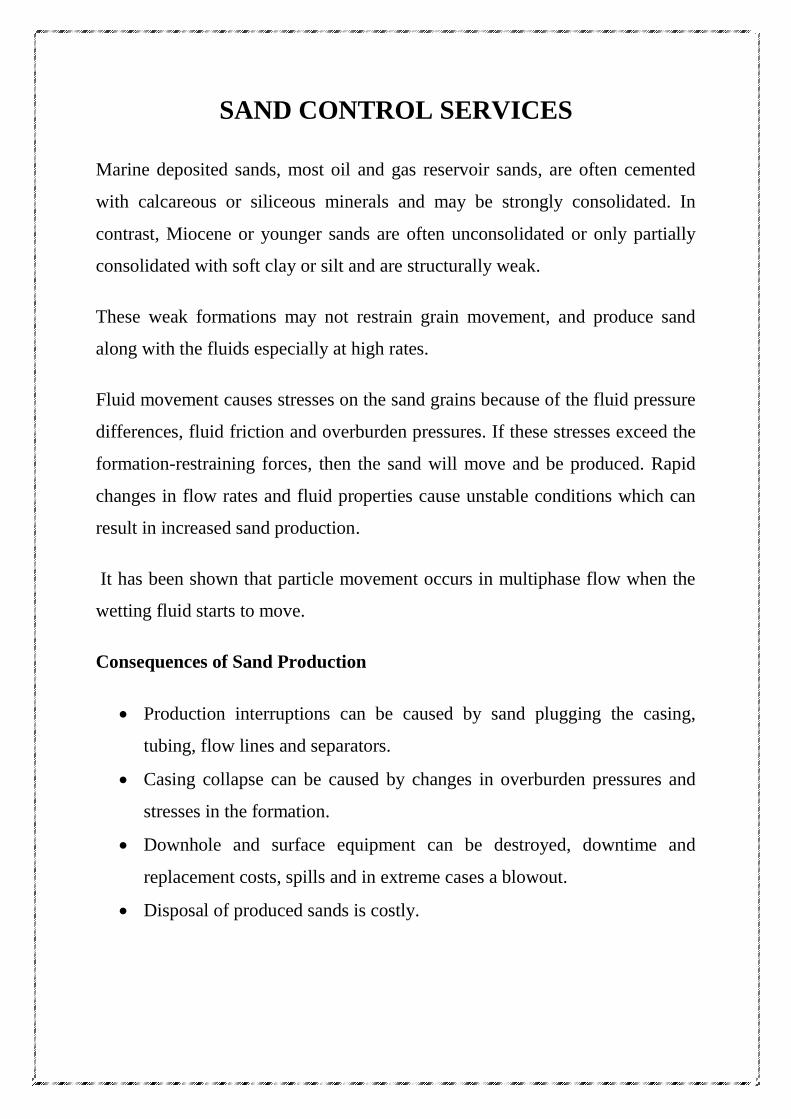
SAND CONTROL SERVICES
Marine deposited sands, most oil and gas reservoir sands, are often cemented
with calcareous or siliceous minerals and may be strongly consolidated. In
contrast, Miocene or younger sands are often unconsolidated or only partially
consolidated with soft clay or silt and are structurally weak.
These weak formations may not restrain grain movement, and produce sand
along with the fluids especially at high rates.
Fluid movement causes stresses on the sand grains because of the fluid pressure
differences, fluid friction and overburden pressures. If these stresses exceed the
formation-restraining forces, then the sand will move and be produced. Rapid
changes in flow rates and fluid properties cause unstable conditions which can
result in increased sand production.
It has been shown that particle movement occurs in multiphase flow when the
wetting fluid starts to move.
Consequences of Sand Production
Production interruptions can be caused by sand plugging the casing,
tubing, flow lines and separators.
Casing collapse can be caused by changes in overburden pressures and
stresses in the formation.
Downhole and surface equipment can be destroyed, downtime and
replacement costs, spills and in extreme cases a blowout.
Disposal of produced sands is costly.
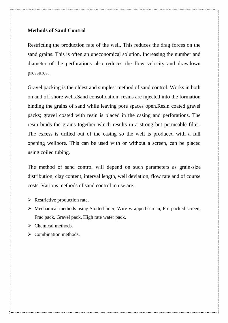
Methods of Sand Control
Restricting the production rate of the well. This reduces the drag forces on the
sand grains. This is often an uneconomical solution. Increasing the number and
diameter of the perforations also reduces the flow velocity and drawdown
pressures.
Gravel packing is the oldest and simplest method of sand control. Works in both
on and off shore wells.Sand consolidation; resins are injected into the formation
binding the grains of sand while leaving pore spaces open.Resin coated gravel
packs; gravel coated with resin is placed in the casing and perforations. The
resin binds the grains together which results in a strong but permeable filter.
The excess is drilled out of the casing so the well is produced with a full
opening wellbore. This can be used with or without a screen, can be placed
using coiled tubing.
The method of sand control will depend on such parameters as grain-size
distribution, clay content, interval length, well deviation, flow rate and of course
costs. Various methods of sand control in use are:
Restrictive production rate.
Mechanical methods using Slotted liner, Wire-wrapped screen, Pre-packed screen,
Frac pack, Gravel pack, High rate water pack.
Chemical methods.
Combination methods.
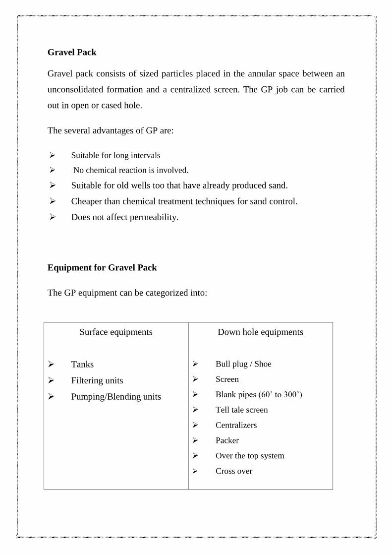
Gravel Pack
Gravel pack consists of sized particles placed in the annular space between an
unconsolidated formation and a centralized screen. The GP job can be carried
out in open or cased hole.
The several advantages of GP are:
Suitable for long intervals
No chemical reaction is involved.
Suitable for old wells too that have already produced sand.
Cheaper than chemical treatment techniques for sand control.
Does not affect permeability.
Equipment for Gravel Pack
The GP equipment can be categorized into:
Surface equipments
Tanks
Filtering units
Pumping/Blending units
Down hole equipments
Bull plug / Shoe
Screen
Blank pipes (60’ to 300’)
Tell tale screen
Centralizers
Packer
Over the top system
Cross over
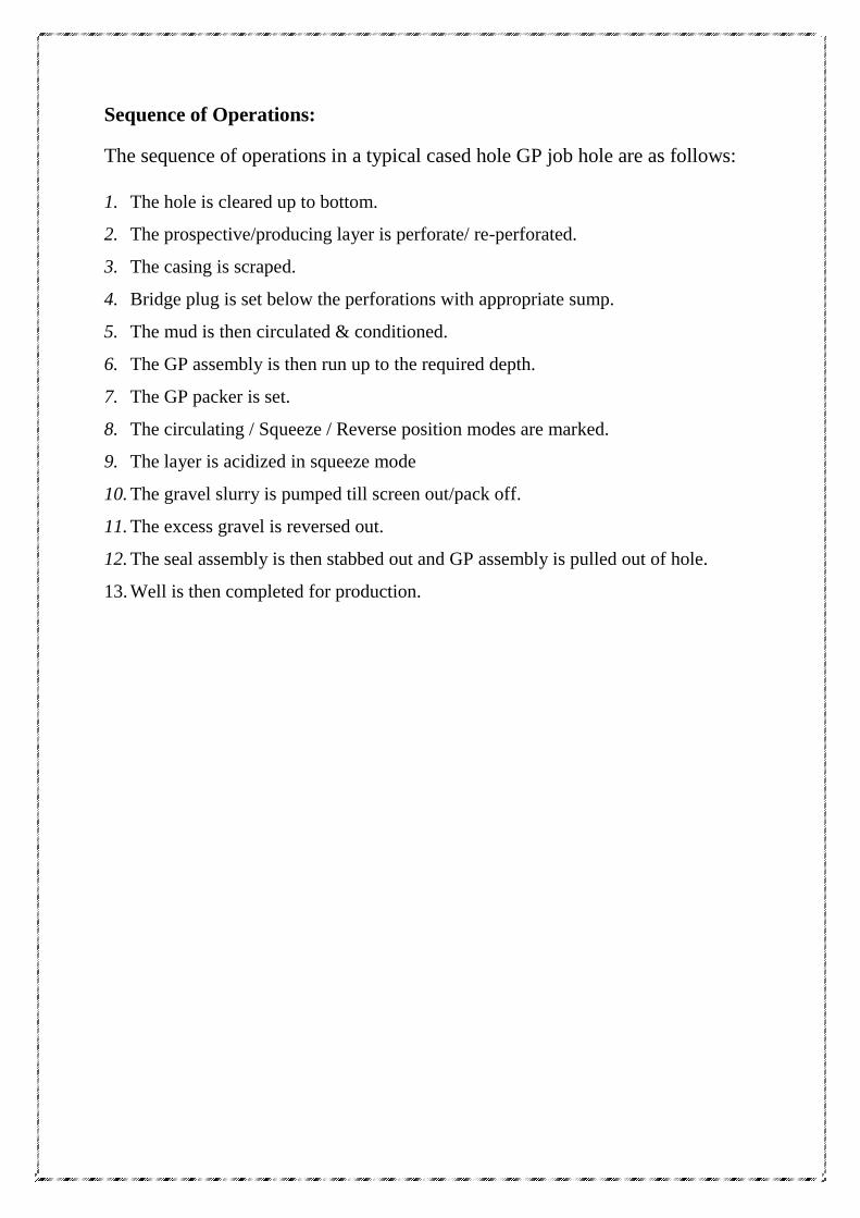
Sequence of Operations:
The sequence of operations in a typical cased hole GP job hole are as follows:
1. The hole is cleared up to bottom.
2. The prospective/producing layer is perforate/ re-perforated.
3. The casing is scraped.
4. Bridge plug is set below the perforations with appropriate sump.
5. The mud is then circulated & conditioned.
6. The GP assembly is then run up to the required depth.
7. The GP packer is set.
8. The circulating / Squeeze / Reverse position modes are marked.
9. The layer is acidized in squeeze mode
10. The gravel slurry is pumped till screen out/pack off.
11. The excess gravel is reversed out.
12. The seal assembly is then stabbed out and GP assembly is pulled out of hole.
13. Well is then completed for production.
HOT OIL SERVICES
A problem that has plagued producers since the discovery of the first oil well is
that of paraffin deposition in well tubular. This is especially true for oils with a
high asphaltine base.
The low ends of oil may build up on the tubular to the extent of completely
shutting off production. Usually production gets chocked with solid paraffin
deposition in upper portion.
An effective method of removing paraffin build-up is to melt the paraffin with
hot oil/hot water/chemicals circulation. Specially designed Hot Oil Units are
used to heat the oil/water to a temperature of 2000 to 5000 F and either
bullhead it into the well or circulate it through a work string.
If the paraffin depositing is solid it will often have to be “washed” out with a
work string.
Common Procedure for Paraffin Removal from the Well Tubing
using CTU :-
Common procedure to remove paraffin from the tubing involves rigging up of
CTU in standard manner and circulating hot oil using hot oil unit. A high
temperature pack-off rubber should be used in the pack-off. Procedure in brief
is as described below.
1. The hot oil unit discharge line is connected to the rotating hub of the CTU
reel. Hot oil/hot water/chemicals should be circulated through the CT until
the CT is hot prior to going in the hole.
2. Circulation of the hot fluid should be maintained from surface to
approximately 500 feet below the fresh water zones. Circulation should be
maintained for at least two hours after reaching the desired depth. This will
ensure melting away all the paraffin rather than simply washing a hole
through it.
3. Returns should be monitored to be sure the oil is hot enough to melt the
paraffin before circulation is stopped.
4. Extreme caution should be used when working around hot oil. If the hot
come in contact with someone, then creates severe burn.
5. Hot water and chemicals can also be used for paraffin removal depending
upon the situation.

CASE STUDY
CASE STUDY
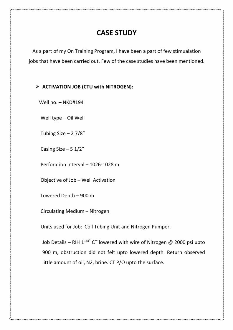
As a part of my On Training Program, I have been a part of few stimualation
jobs that have been carried out. Few of the case studies have been mentioned.
ACTIVATION JOB (CTU with NITROGEN):
Well no. – NKD#194
Well type – Oil Well
Tubing Size – 2 7/8”
Casing Size – 5 1/2”
Perforation Interval – 1026-1028 m
Objective of Job – Well Activation
Lowered Depth – 900 m
Circulating Medium – Nitrogen
Units used for Job: Coil Tubing Unit and Nitrogen Pumper.
Job Details – RIH 11/4” CT lowered with wire of Nitrogen @ 2000 psi upto
900 m, obstruction did not felt upto lowered depth. Return observed
little amount of oil, N2, brine. CT P/O upto the surface.
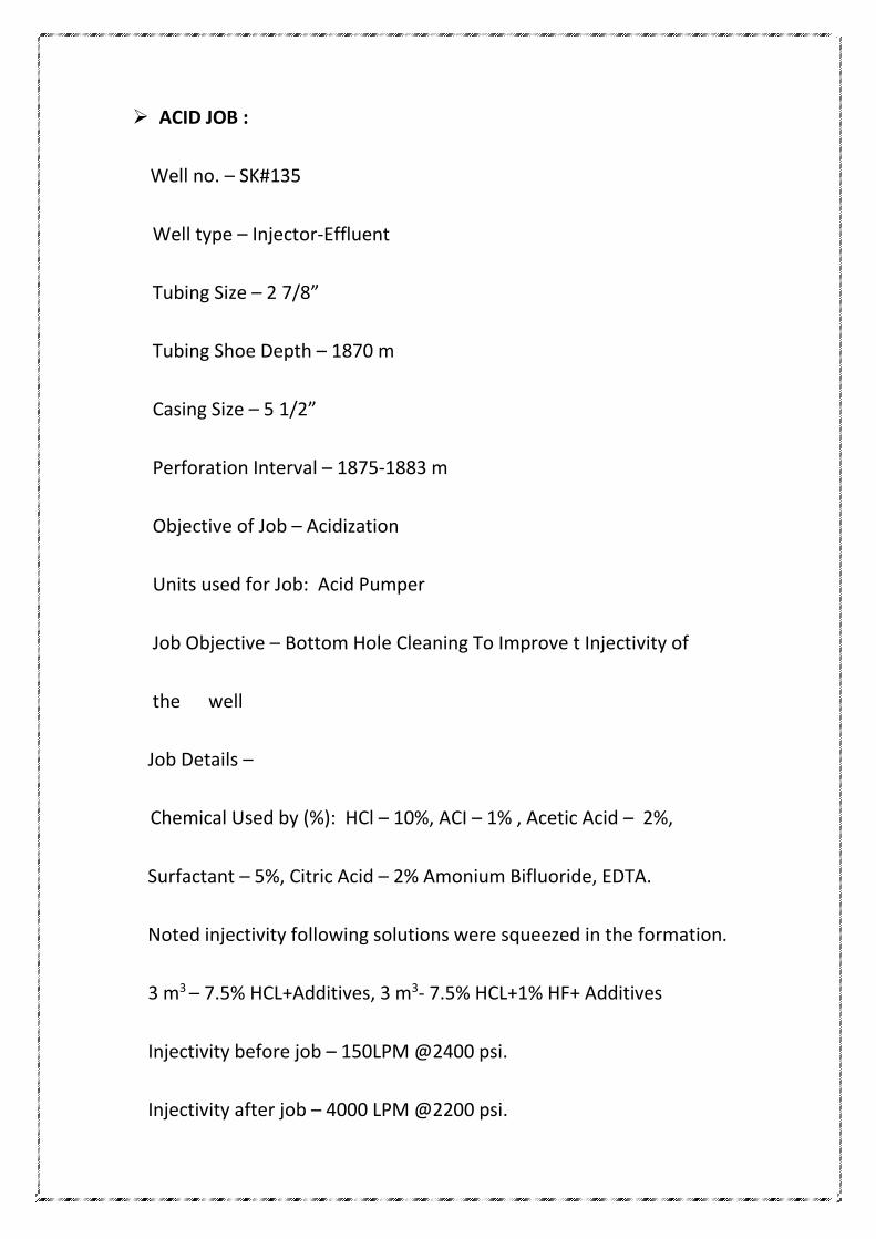
ACID JOB :
Well no. – SK#135
Well type – Injector-Effluent
Tubing Size – 2 7/8”
Tubing Shoe Depth – 1870 m
Casing Size – 5 1/2”
Perforation Interval – 1875-1883 m
Objective of Job – Acidization
Units used for Job: Acid Pumper
Job Objective – Bottom Hole Cleaning To Improve t Injectivity of
the well
Job Details –
Chemical Used by (%): HCl – 10%, ACI – 1% , Acetic Acid – 2%,
Surfactant – 5%, Citric Acid – 2% Amonium Bifluoride, EDTA.
Noted injectivity following solutions were squeezed in the formation.
3 m3 – 7.5% HCL+Additives, 3 m3- 7.5% HCL+1% HF+ Additives
Injectivity before job – 150LPM @2400 psi.
Injectivity after job – 4000 LPM @2200 psi.
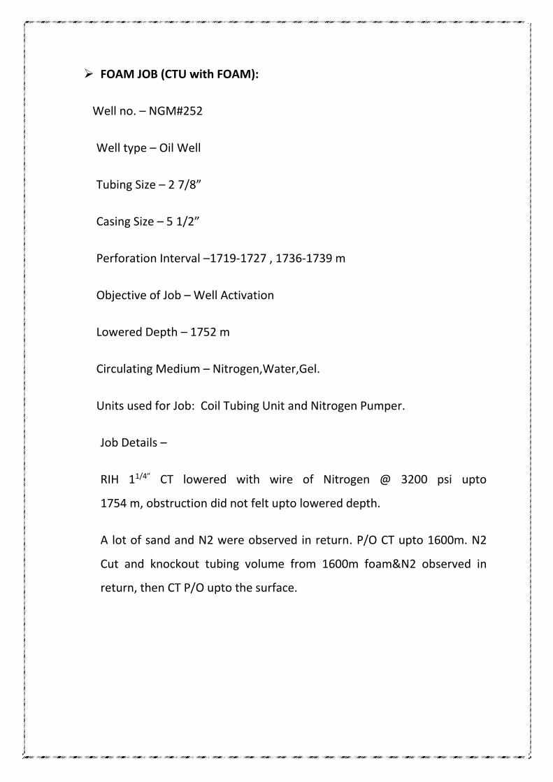
FOAM JOB (CTU with FOAM):
Well no. – NGM#252
Well type – Oil Well
Tubing Size – 2 7/8”
Casing Size – 5 1/2”
Perforation Interval –1719-1727 , 1736-1739 m
Objective of Job – Well Activation
Lowered Depth – 1752 m
Circulating Medium – Nitrogen,Water,Gel.
Units used for Job: Coil Tubing Unit and Nitrogen Pumper.
Job Details –
RIH 11/4” CT lowered with wire of Nitrogen @ 3200 psi upto
1754 m, obstruction did not felt upto lowered depth.
A lot of sand and N2 were observed in return. P/O CT upto 1600m. N2
Cut and knockout tubing volume from 1600m foam&N2 observed in
return, then CT P/O upto the surface.
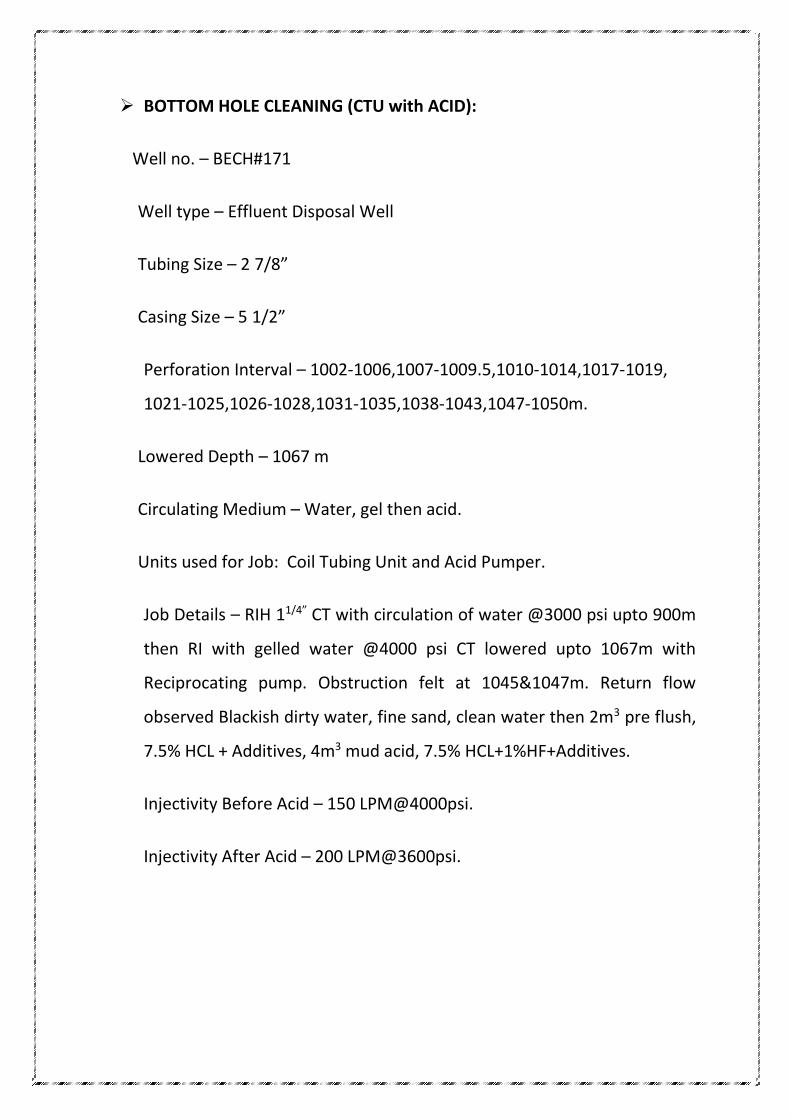
BOTTOM HOLE CLEANING (CTU with ACID):
Well no. – BECH#171
Well type – Effluent Disposal Well
Tubing Size – 2 7/8”
Casing Size – 5 1/2”
Perforation Interval – 1002-1006,1007-1009.5,1010-1014,1017-1019,
1021-1025,1026-1028,1031-1035,1038-1043,1047-1050m.
Lowered Depth – 1067 m
Circulating Medium – Water, gel then acid.
Units used for Job: Coil Tubing Unit and Acid Pumper.
Job Details – RIH 11/4” CT with circulation of water @3000 psi upto 900m
then RI with gelled water @4000 psi CT lowered upto 1067m with
Reciprocating pump. Obstruction felt at 1045&1047m. Return flow
observed Blackish dirty water, fine sand, clean water then 2m3 pre flush,
7.5% HCL + Additives, 4m3 mud acid, 7.5% HCL+1%HF+Additives.
Injectivity Before Acid – 150 LPM@4000psi.
Injectivity After Acid – 200 LPM@3600psi.
HOC JOB:
Well no. – KL#431
Well type – Oil Well
Problem in the Well – Wax Deposition
Tubing Size – 2 7/8”
Casing Size – 5 1/2”
Packer – SRP
Objective of Job – Hot oil circulation
Circulating Medium – Hot Oil
Units used for Job: Oil tanker and hot oil Pumper.
Job Details –
Oil was transferred from oil tanker to the hoc unit where it was heated
at 850 C and then pumped into the well in the annulus. Circulated oil and
produced oil was observed in return.
HYDRO FRACTURING JOB :
Well no. – GM#152
Well type – Oil
Tubing Size – 2 7/8”
Tubing Shoe Depth – 1000.36 m
Casing Size – 5 1/2”
Perforation Interval – 1012-1017m
Objective of Job – To increase the permeability
Units used for Job: Acid Pumper
Job Objective – Productivity improvement
Frac Fluid – X- linked Guar Gel
Job Details –
Chemical Used:-
Proppant- 37 mt, KCL- 3 mt
G.A(Grade II),.-1000 kg, Borax- 50kg, Soda ash- 150kg, Surfactant- 720kg,
Acetic acid- 30kg, APS- 70kg,TEA- 50kg, Biocide- 60 lt.
The units that were employed for the hydrofracturing job are:
Frac Pumpers - 3
Blender - 1
Sand Dumpers - 2
Fracvan - 1
Acid pumper - 1
Lorry Loader - 1
Frac Tanks - 3
Job detail - The total frac fluid was 37 MT which was placed in the well at
an avg. 2471 psi. the injectivity was 13 bpm and the breakdown pressure was
1571 psi.
Gravel Pack Job:
Well no. – SNL#261
Well type – Oil Well
Well Depth- 1174m
Screen length- 9.28m
Problem in the Well – Sand Production
Tubing Size – 3 1/2”
Casing Size – 7
Objective of Job – To minimize the sand production
Rig - John- 5
Job Details –
Firstly screen was placed at the perforation interval.5 MT Gel was prepared
first, was a mixture of HSC(Hydroxy Ethyl Cellulose) plus brine (1.2 S.g) plus ISP
(Proppant). Then gel was placed in the well at 2000 psi. in return broken gel
was observed.