Embed Size (px)
Citation preview

MEMS FILTER WITH VOLTAGE TUNABLE CENTER FREQUENCYAND BANDWIDTH
Lih Feng Cheow, Hengky Chandrahalim, and Sunil A. BhaveOxideMEMS Lab, 102 Phillips Hall, Cornell University, Ithaca, NY 14853, USA
ABSTRACT
This paper reports on the design of a reconfigurable ladder filterusing RF MEMS resonators with voltage-tunable series andparallel resonance frequencies. The ladder filter consists of oneshunt and two series resonators operating in the half-wavethickness shear vibration mode. It demonstrates a center frequencytuning range of 8 MHz at 817 MHz and an adjustable bandwidthfrom 600 kHz to 2.8 MHz, while maintaining an insertion loss < 4dB, stop-band rejection > 30 dB and pass-band ripple < 2 dB. Thisvoltage tunable design enables channel agility andreconfigurability, substantially reducing the filter count in channel-select radio receiver architectures. Finally, a simple algorithm isprovided to facilitate dynamic tuning of filter center frequency andbandwidth.
INTRODUCTION
Multi-band, multi-standard radio receivers require a large array ofchannel-select filters connected in parallel. The input capacitanceof the filter array will ‘load’ individual filters, deteriorating theirstop-band rejection. For reconfigurable radios the front-end filtersmust also handle encoded waveforms with different bandwidthrequirements. A filter with dynamically tunable center frequencyand bandwidth will not only overcome fabrication tolerances andthermal drift, but will also reduce capacitive loading at the filterinput, enable handling of multiple waveforms, and substantiallydecrease the number of filters in next-generation receivers.
Low frequency filters comprised of electrostatically-coupledresonators have been demonstrated with 10× bandwidth tunability[1]. However, it is challenging to implement electrostatic couplingsprings at GHz frequencies even with 100 nm air-gaps. Galayko etal presented a tunable bandwidth filter using clamped-clampedbeam resonators in a ladder configuration [2]. The firsttransmission zero (and hence filter bandwidth) was tuned bycontrolling the series resonance frequency of the shunt resonator,though large parasitic capacitance prevented implementation andtunability of the second transmission zero of the filter.
In a typical ladder filter configuration, parallel of the shuntresonator, which defines the filter center frequency fc, is matchedto series of the series resonators. Filter bandwidth (BW) isdetermined by notches on either side of the pass-band and is 2× thepole-zero separation of the series and shunt resonators. The key totunable ladder filters is the ability to change fc and to dynamicallytune the pole-zero separation parallel - series of the resonators. Wehave previously demonstrated channel-select ladder filters with600 kHz bandwidth, 25 dB stop-band rejection, excellent shapefactor, and low insertion loss (IL) using dielectrically-transducedthickness shear mode resonators [3]. In this paper, we introduce avoltage biasing scheme capable of independently tuning the seriesresonance and pole-zero separation of the filter’s constituentresonators. Coupled with orthogonal frequency tuning [4], we canconfigure the filter with desired pass-band characteristic in realtime.
ORTHOGONAL FREQUENCY TUNING
The series resonance of low frequency resonators can be tuned byelectrostatic spring tuning. However, the stiffness of highfrequency resonators is quite large (a 1 GHz bulk-mode resonatorhas stiffness on the order of 1 MN/m in the resonant direction) andwould require considerable electrostatic force to tune the stiffnessand the series resonance frequency.
Figure 1. Longitudinal cross-section of a half-wave thicknessshear mode resonator. The tuning voltage Vp-Vs generates avertical force and bends the silicon bar in the vertical direction,thereby changing the effective stiffness of the resonator.
In contrast, orthogonal frequency tuning deforms the resonator in adirection perpendicular to the direction of vibration. The resonatorsare generally less stiff in the orthogonal direction and can bedeformed with substantially less force. The symmetric half-wavethickness shear mode resonator exhibits a small-amplitude flexuremode coupled to the shear mode [3]. The Southwell-Dunkerleyformula approximates the combined shear-flexure frequency as
222111
flexuresheartotal fff.
When a polarization voltage Vp is applied to the resonator and avoltage Vs is applied to the substrate, the tuning voltage Vp-Vsgenerates an electrostatic force that deflects the structure towardsthe substrate, as illustrated in Figure 1. Bending the structuresoftens the flexural mode stiffness, lowering the series resonancefrequency.
POLE-ZERO SEPARATION TUNING
A dielectrically transduced MEMS resonator can be represented byan equivalent series LCR circuit in parallel with a feedthroughcapacitance Cft, as shown in Figure 2. For a given transductionefficiency Vp C/ x, RX = b/ 2, CX = 2/K, and LX = M/ 2,where b, K and M denote the damping constant, effective springstiffness and effective mass of the resonator. The feedthroughcapacitance in a two-port resonator originates from electric fieldcoupling from the input electrode to the output electrode and is afunction of electrode geometry. The series resonance frequency isgiven by
MK
CL xxseries
1.
silicon tether
silicon substrate
polysiliconelectrode
hafniumdioxide
VP-VS
silicon tether
silicon substrate
polysiliconelectrode
hafniumdioxide
VP-VS
Solid-State Sensors, Actuators, and Microsystems Workshop0-9640024-6-9/hh2006/$20©2006TRF 304 Hilton Head Island, South Carolina, June 4-8, 2006
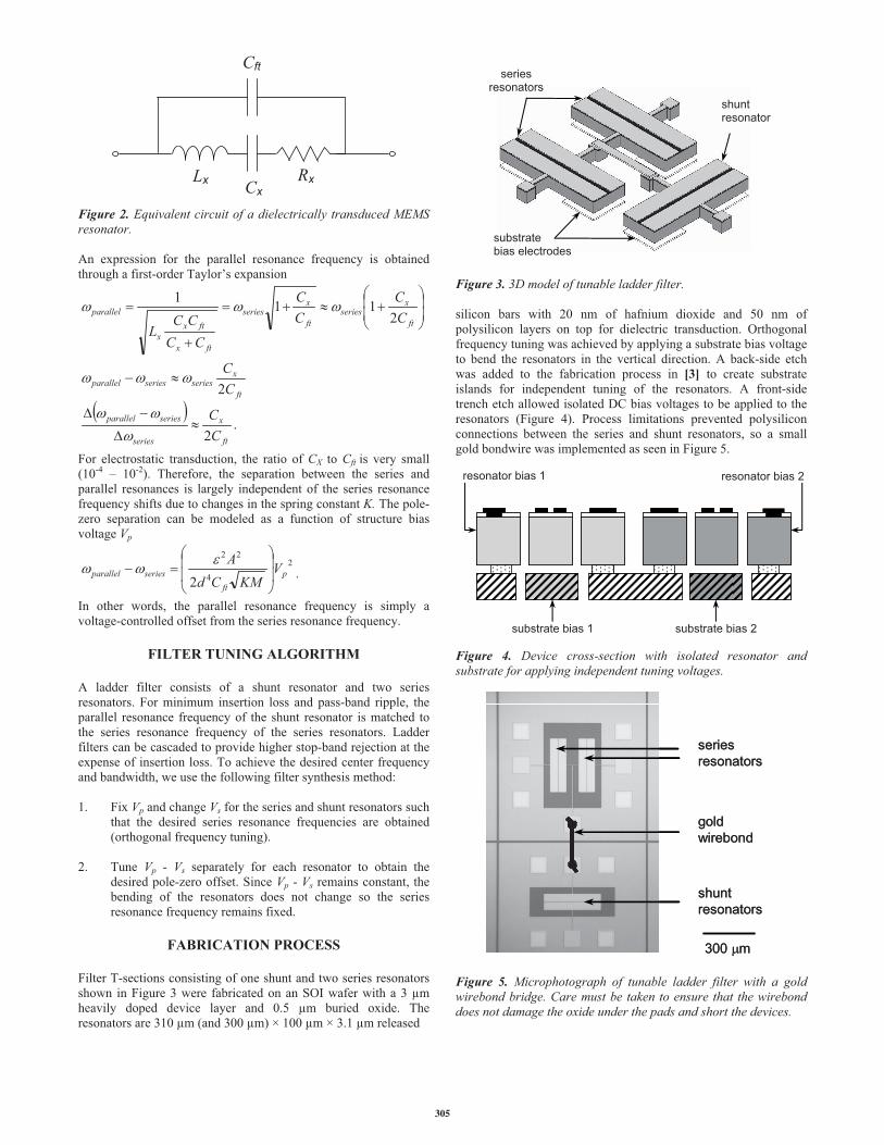
Figure 2. Equivalent circuit of a dielectrically transduced MEMSresonator.
An expression for the parallel resonance frequency is obtainedthrough a first-order Taylor’s expansion
.2
2
2111
ft
x
series
seriesparallel
ft
xseriesseriesparallel
ft
xseries
ft
xseries
ftx
ftxx
parallel
CC
CC
CC
CC
CCCC
L
For electrostatic transduction, the ratio of CX to Cft is very small(10-4 – 10-2). Therefore, the separation between the series andparallel resonances is largely independent of the series resonancefrequency shifts due to changes in the spring constant K. The pole-zero separation can be modeled as a function of structure biasvoltage Vp
2
4
22
2p
ftseriesparallel V
KMCdA
.
In other words, the parallel resonance frequency is simply avoltage-controlled offset from the series resonance frequency.
FILTER TUNING ALGORITHM
A ladder filter consists of a shunt resonator and two seriesresonators. For minimum insertion loss and pass-band ripple, theparallel resonance frequency of the shunt resonator is matched tothe series resonance frequency of the series resonators. Ladderfilters can be cascaded to provide higher stop-band rejection at theexpense of insertion loss. To achieve the desired center frequencyand bandwidth, we use the following filter synthesis method:
1. Fix Vp and change Vs for the series and shunt resonators suchthat the desired series resonance frequencies are obtained(orthogonal frequency tuning).
2. Tune Vp - Vs separately for each resonator to obtain thedesired pole-zero offset. Since Vp - Vs remains constant, thebending of the resonators does not change so the seriesresonance frequency remains fixed.
FABRICATION PROCESS
Filter T-sections consisting of one shunt and two series resonatorsshown in Figure 3 were fabricated on an SOI wafer with a 3 µmheavily doped device layer and 0.5 µm buried oxide. Theresonators are 310 µm (and 300 µm) × 100 µm × 3.1 µm released
Figure 3. 3D model of tunable ladder filter.
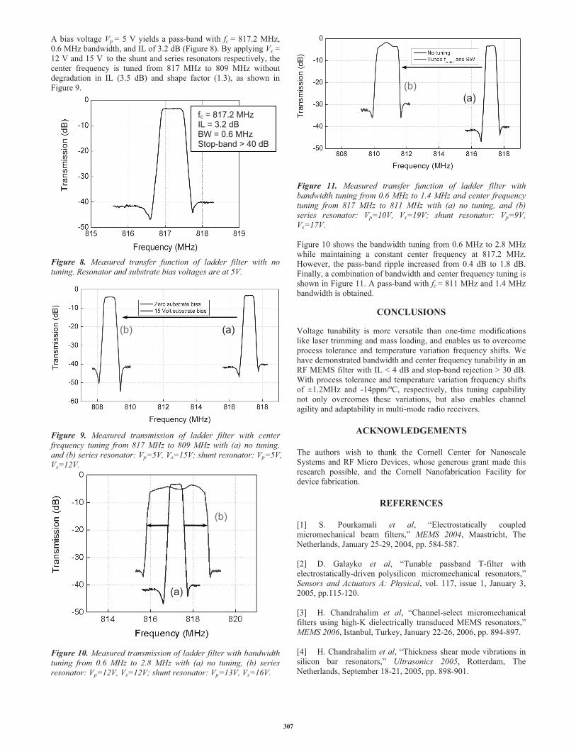
silicon bars with 20 nm of hafnium dioxide and 50 nm ofpolysilicon layers on top for dielectric transduction. Orthogonalfrequency tuning was achieved by applying a substrate bias voltageto bend the resonators in the vertical direction. A back-side etchwas added to the fabrication process in [3] to create substrateislands for independent tuning of the resonators. A front-sidetrench etch allowed isolated DC bias voltages to be applied to theresonators (Figure 4). Process limitations prevented polysiliconconnections between the series and shunt resonators, so a smallgold bondwire was implemented as seen in Figure 5.
Figure 4. Device cross-section with isolated resonator andsubstrate for applying independent tuning voltages.
Figure 5. Microphotograph of tunable ladder filter with a goldwirebond bridge. Care must be taken to ensure that the wirebonddoes not damage the oxide under the pads and short the devices.
substrate bias 1
resonator bias 1 resonator bias 2
substrate bias 2
seriesresonators
substratebias electrodes
Cft
RxLx Cx
shuntresonator
seriesresonators
goldwirebond
shuntresonators
300 m
seriesresonators
goldwirebond
shuntresonators
300 m
305

EXPERIMENTAL RESULTS
The resonators and filters were characterized using a DesertCryomicrowave probe station. The resonator proof-mass was groundedand a DC bias Vp was applied to both the drive and senseelectrodes with MiniCircuits bias-Ts. Quality factorcharacterization and S21 transmission measurements wereperformed using an Agilent 8722ES Network Analyzer. Theresonators and filters were terminated with 50 and 500impedances, respectively.
Measurement results demonstrating orthogonal frequency tuningare shown in Figure 6. Keeping Vp constant at 5V and varying thesubstrate bias Vs from 5V to 17V, we can tune the series resonancefrequency of a single resonator from 816 MHz to 802 MHz, whilemaintaining a quality factor Q > 7000. The parallel and seriesresonance separation does not change during orthogonal frequencytuning.
Figure 7 shows that the pole-zero separation of the resonator variesfrom 0.6 MHz to 1.6 MHz when Vp is changed from 5V to 12V.The substrate bias Vs was held at Vp during this measurement toprevent orthogonal forces acting on the resonator.
Figure 6. (a) Measured series resonance tuning for Vs = 5V and Vs= (i) 12 V, (ii) 8 V, and (iii) 5 V. Orthogonal frequency tuningshifts series and parallel resonances by equal amount. (b)Resonant frequency tuning vs. substrate voltage. A tuning range of15 MHz is observed while maintaining Q > 7000.
Figure 7. (a,b,c) Measured transmission response demonstratingpole-zero separation of a thickness shear mode resonator as DCbias Vp increases from 5V to 10V. (d) Measured pole-zeroseparation vs. DC bias voltage of the resonator.
(a)
(b)
i) 808.5MHz
ii) 813MHz
iii) 816MHz
Vp= 10 Vzero-pole:1.2 MHz
(a)
(b)
(c)
Vp= 7 Vzero-pole:0.88 MHz
Vp= 5 Vzero-pole:0.6 MHz
(d)
306
A bias voltage Vp = 5 V yields a pass-band with fc = 817.2 MHz,0.6 MHz bandwidth, and IL of 3.2 dB (Figure 8). By applying Vs =12 V and 15 V to the shunt and series resonators respectively, thecenter frequency is tuned from 817 MHz to 809 MHz withoutdegradation in IL (3.5 dB) and shape factor (1.3), as shown inFigure 9.
Figure 8. Measured transfer function of ladder filter with notuning. Resonator and substrate bias voltages are at 5V.
Figure 9. Measured transmission of ladder filter with centerfrequency tuning from 817 MHz to 809 MHz with (a) no tuning,and (b) series resonator: Vp=5V, Vs=15V; shunt resonator: Vp=5V,Vs=12V.
Figure 10. Measured transmission of ladder filter with bandwidthtuning from 0.6 MHz to 2.8 MHz with (a) no tuning, (b) seriesresonator: Vp=12V, Vs=12V; shunt resonator: Vp=13V, Vs=16V.
Figure 11. Measured transfer function of ladder filter withbandwidth tuning from 0.6 MHz to 1.4 MHz and center frequencytuning from 817 MHz to 811 MHz with (a) no tuning, and (b)series resonator: Vp=10V, Vs=19V; shunt resonator: Vp=9V,Vs=17V.
Figure 10 shows the bandwidth tuning from 0.6 MHz to 2.8 MHzwhile maintaining a constant center frequency at 817.2 MHz.However, the pass-band ripple increased from 0.4 dB to 1.8 dB.Finally, a combination of bandwidth and center frequency tuning isshown in Figure 11. A pass-band with fc = 811 MHz and 1.4 MHzbandwidth is obtained.
CONCLUSIONS
Voltage tunability is more versatile than one-time modificationslike laser trimming and mass loading, and enables us to overcomeprocess tolerance and temperature variation frequency shifts. Wehave demonstrated bandwidth and center frequency tunability in anRF MEMS filter with IL < 4 dB and stop-band rejection > 30 dB.With process tolerance and temperature variation frequency shiftsof ±1.2MHz and -14ppm/ºC, respectively, this tuning capabilitynot only overcomes these variations, but also enables channelagility and adaptability in multi-mode radio receivers.
ACKNOWLEDGEMENTS
The authors wish to thank the Cornell Center for NanoscaleSystems and RF Micro Devices, whose generous grant made thisresearch possible, and the Cornell Nanofabrication Facility fordevice fabrication.
REFERENCES
[1] S. Pourkamali et al, “Electrostatically coupledmicromechanical beam filters,” MEMS 2004, Maastricht, TheNetherlands, January 25-29, 2004, pp. 584-587.
[2] D. Galayko et al, “Tunable passband T-filter withelectrostatically-driven polysilicon micromechanical resonators,”Sensors and Actuators A: Physical, vol. 117, issue 1, January 3,2005, pp.115-120.
[3] H. Chandrahalim et al, “Channel-select micromechanicalfilters using high-K dielectrically transduced MEMS resonators,”MEMS 2006, Istanbul, Turkey, January 22-26, 2006, pp. 894-897.
[4] H. Chandrahalim et al, “Thickness shear mode vibrations insilicon bar resonators,” Ultrasonics 2005, Rotterdam, TheNetherlands, September 18-21, 2005, pp. 898-901.
(a)
(b)
fc = 817.2 MHzIL = 3.2 dBBW = 0.6 MHzStop-band > 40 dB
(a)(b)
(a)(b)
307