Embed Size (px)
Citation preview
Interim Report
A NON-OVERLAY CATHODIC PROTECTION SYSTEM
by
Gerardo G. Cleme•a Re s ear'ch Scientist
(The opinions, findings, and conclusions expressed in this report are those of the author and not necessarily those of
the sponsoring agencies.)
Virginia Highway $ Transportation Research Council (A Cooperative Organization Sponsored Jointly by the Virginia
Department of Highways • Transportation and the University of Virginia)
In Cooperation with the U. S. Department of Transportation Federal Highway Administration
Charlottesville, Virginia
August 1983 VHTRC 84-R5
BRIDGE RESEARCH ADVISORY COMMITTEE
L. L. MISENHEIMER, Chairman, District Bridge Engineer, VDH&T
J. E. ANDREWS, Bridge Design Engineer Supervisor, VDH&T
F. L. BURROUGHS, Construction Engineer, Central Office
Co L. CHAMBERS, Division Bridge Engineer, FHWA
M. H. HILTON, Senior Research Scientist, VH&TRC
H. L. KINNIER, Consultant, VH&TRC
J. G. G. MCGEE, Construction Control Engineer, •/DH&T
M. F. MENEFE•, JR., Structural Steel Engineer, VDH&T
R. H. MORECOCK, District Bridge Engineer, VDH&T
C. A. NASH, JR., District Engineer, VDH&T
F. L. PREWOZNIK, District Bridge Engineer, VDH&T
W. L. SELLARS, District Bridge Engineer, VDH&T
F. G. SUTHERLAND, Bridge Engineer, VDH&T
C. P. WILLIAMS, District Materials Engineer, VDH&T
ii

ABSTRACT
This interim report describes Virginia's experience in "nstal!ing its first cathodic protection system for a bridge deck. The installation was completed with practically no problems. Very minor problems have been encountered with the rectifier/control unit. However, these problems haven't pre- vented the system from functioning as designed.
iii

Interim Report
A NON-0VERLAY CATHODIC PROTECTION SYSTEM
by
Gerardo G. Cleme•a Research Scientist
INTRODUCTION
A non-overlay, impressed-current cathodic protection (CP) system for sto.pping the corrosion of reinforcing bars in bridge decks was recently installed on a bridge deck on Route 15 that crosses the Willis River in Buckingham County, Virginia. This installation represents Virginia's participation in the Federal Highway Administration's Demonstration Project No. 34.
This system consists of three electrical circuits that serve the three physically and electrically isolated spans, each approxi- mately ii.4 m (37.5 ft.) long x.8.5 m (28.0 ft.) wide, that make up the deck. The system has been desi•ned• so that direct cur•en• is brought transversely into each span wi.th two primary anodes separated approximately 7.3 m (24.,0 ft.)apart and made of p lati- nized niobium copper core wires. The current is spread longitu- dinally in the span by secondary anodes made of graphite strands and located at 0.3-m (1-ft.) intervals across the width of the span. Both the primary and secondary anodes are set in slots sawed approximately 1.3 cm (0.50 in.) wide and 2.0 cm (0.75 m) deep and ._•i!led with a conductive polymer concrete.
HISTORY OF INSTALLATION
Work on the design for the system was started in February 1982 with valuable assistance from the Region 15 Demonstration Project Division of the Federal Highway Administration and the bridge office of the Lynchburg District of the Virginia Department of Highways & Transportation. T>•e project was advertised for bid- ding in the latter part of June 1982 and awarded to the lowest bidder, the Lanford Brothers Construction, Inc. of Hollins, Vir- ginia, in early September at the low bid of $52,500.
The installation was commenced on October 7 with the sawing of •he s!o.ts in the northbound lane of the two-lane bridge. A total of 515 fin. m (1,688 lin. ft.) of slo•ts were cut into the concrete in the lane in approximately 5.5 working days. This translates to a rate of i •_, !in. m (35 fin. ft.) of slo•s_ pe•_ hour, a rate •ha*._ must and can be improved upon so that the cost can be reduced.
While the slots_ were being cut, reference cel •=s, rebar probes, and system negative connections were installed.
On October 18, the anodes were laid in the slots in slightly more than 2 hours. Immediately afterwards, the slots were filled with conductive polymer concrete under an early morning temperature of 40°F. Despite this rela•ively• cold tempera " •. •u•e, th=• only problem encountered was difficulty in ensuring a uniform rate of dispensa- tion of the backfill material, which wasn't temperature related. The problem r@sulted from the use of "Zip-Loc" type plastic bags from which the still-pourable backf•l! material was squeezed thro.ugh a small hole cut in a corner. There is a need for a dispensing device that provides better control.
All installations on the northbound lane were completed in 2 weeks. On October 21, similar installations were started in the southbound lane. This work also took approximately 2 meeks.
There was an unusual delay in the delivery of the rectifier/ control (R/C) unit by the manufacturer, Good-All Electric, Inc. of Ogalla!a, Nebraska. The unit wasn't delivered to the general con- tractor until the middle of February 1983. in the latter part of that month, work was begun on connecting the primary anodes, ref- erence cells, rebar probes, and system negatives to the lead wires and routing these wires in conduits on the underside of the deck. This system was completed and connected to a 220 VAC utility line on March 3.
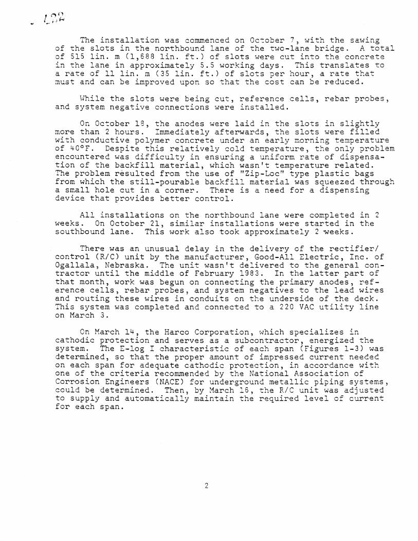
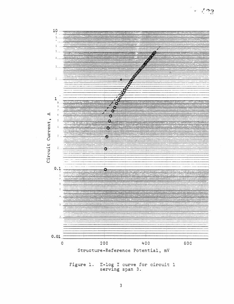
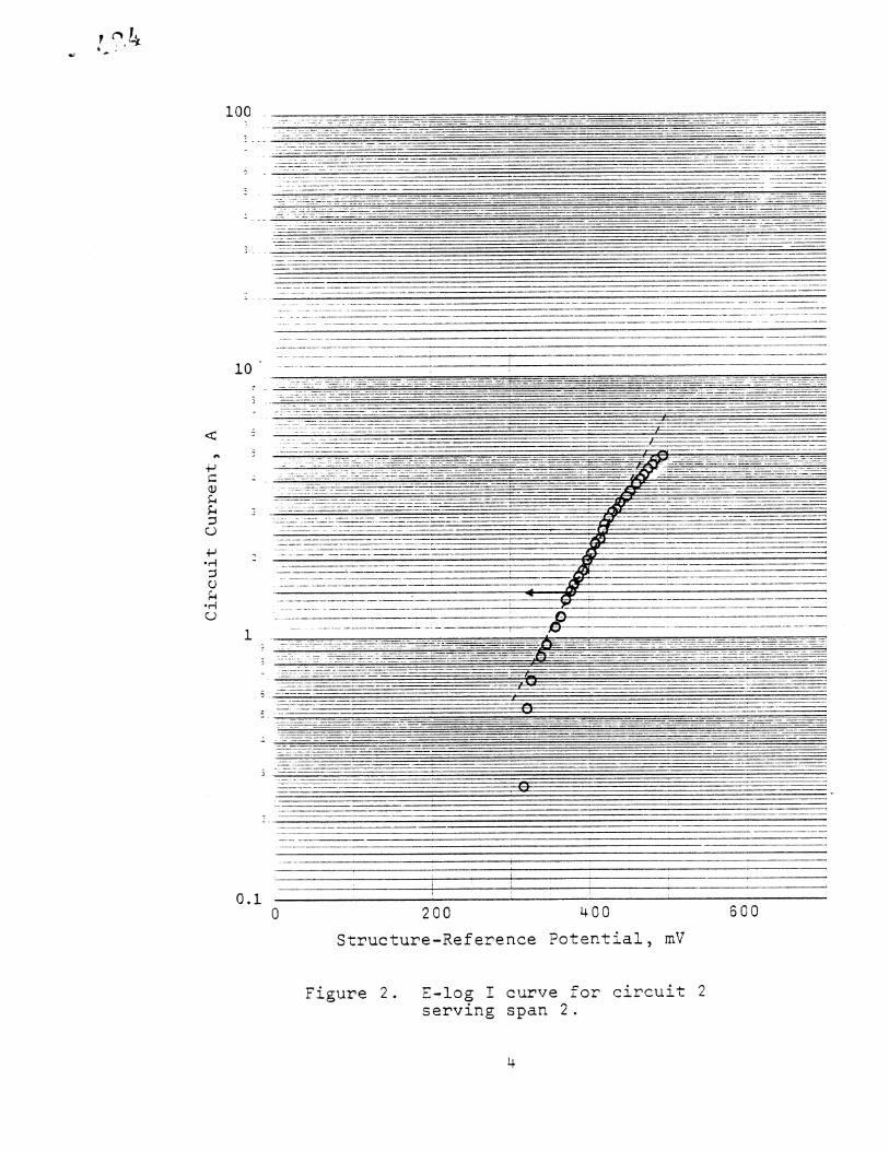
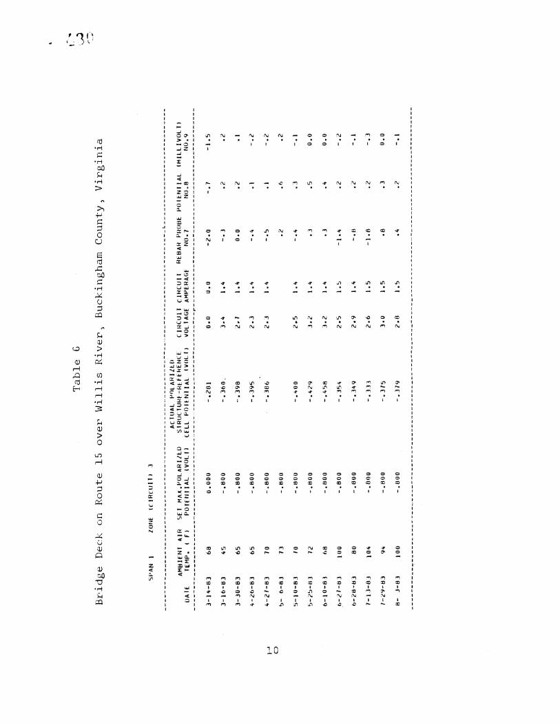
On March 14, the Harco Corporation, which specializes in cathodic protection and serves as a subcontractor, energized the system. The E-log ! characteristic of each span (Figures 1-3) was determined, so that the proper amount of impressed current needed on each span for adequate cathodic protection, in accordance with one of the criteria recommended by the National Association of Corrosion Engineers (NACE) for ,•ndero•ound metallic piping systems, could be determined. Then, by March 16, the R/C unit was adjusted to supply and automatically maintain the required level of current for each span.
O.O1
200 400
Structure-Reference Potential, mV
600
Figure i. E-log I curve for circuit I serving span 3.
i00
20O 400
Structure-Reference Potential, mV
600
Figure 2. E-log ! curve for circuit 2 serving span 2.
l0
j
0.01 200 400
Structure-Reference Potential, mV
600
Figure E-log ! curve for circuit 3 serving span I.
OBSERVATION AND DISCUSSION
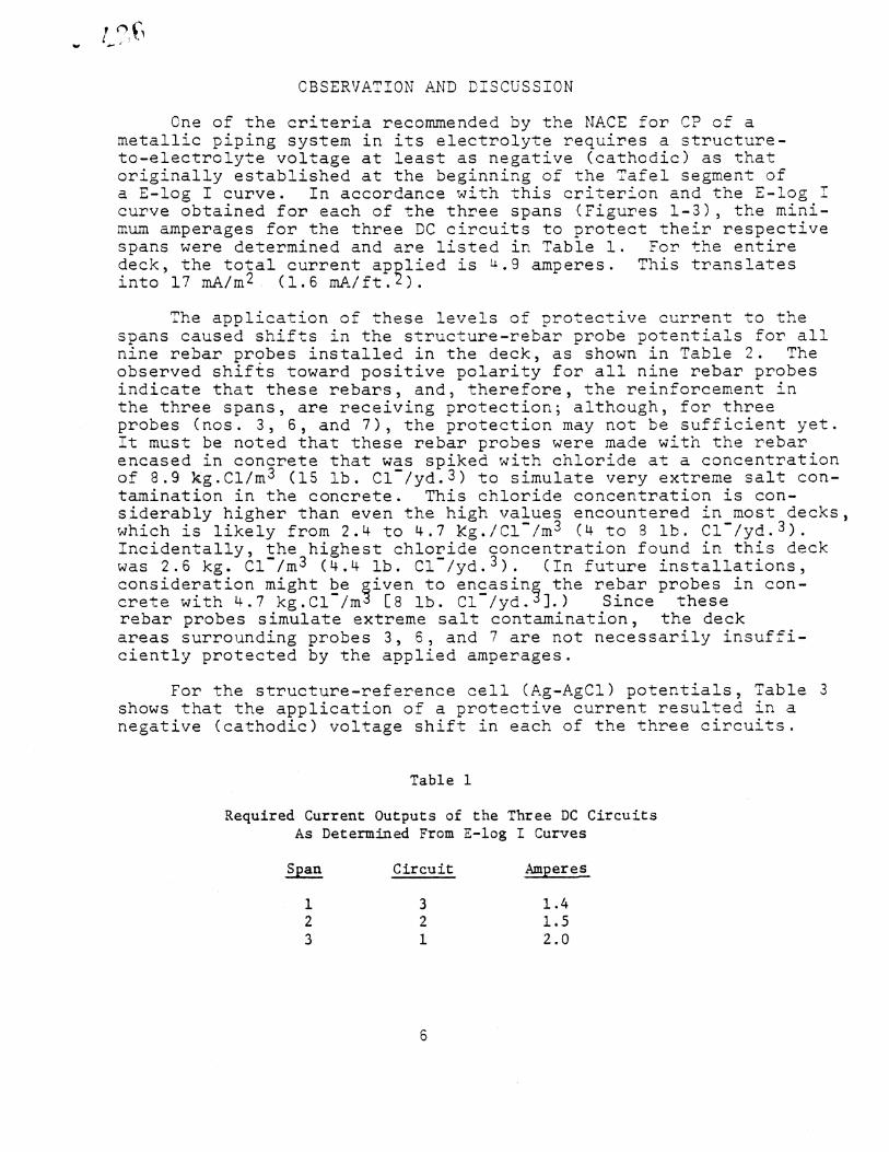
One of the criteria recommended by the NACE for CP of a metallic piping system in its electrolyte requires a structure- to-electrolyte voltage at least as negative (cathodic) as that originally established at the beginning of the Tafe! segment of a r__log I curve. In accordance with this criterion and the E- curve obtained for each of the three spans (Figures I-•), the mini- mum amperages for the three DC circuits to protect their respective spans were determined and are listed in Table I. For the entire deck, the total current applied is a.9 amperes. This translates into 17 mA/m 2 (1.8 mA/ft.2).
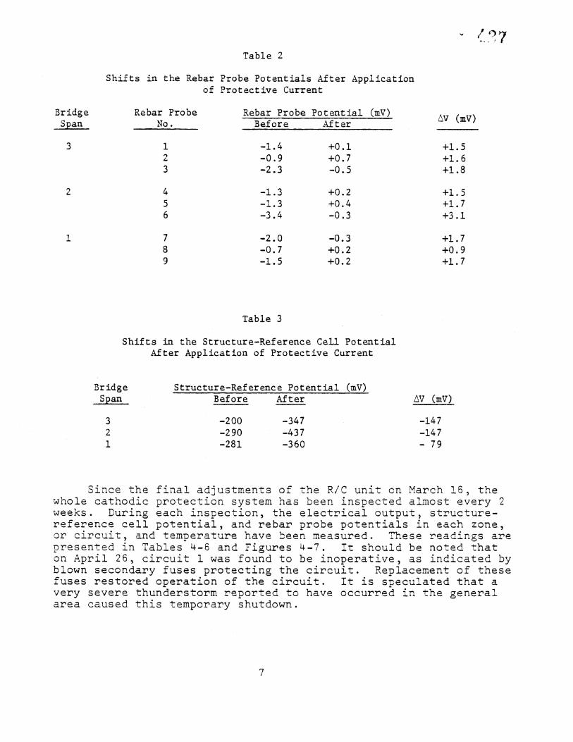
The application of these levels of protective current to the spans caused shifts in the structure-rebar probe potentials for all nine rebar probes installed in the deck, as shown in Table 2. The observed shif%s toward positive polarity for all nine rebar probes indicate that these rebars, and, therefore, the reinforcement in the three spans, are receiving protection; although, for three probes (nos. 3, 6, and 7), the protection may not be sufficient yet. it must be noted that these rebar probes were made with the rebar encased in concrete that was spiked with chloride at a concentration of 8.9 kg. Cl/m 3 (15 lb. Cl-/yd.3) to simulate very extreme salt con- tamination in the concrete. This chloride concentration is con- siderably higher than even the high values encountered in most decks, which is likely from 2.4 to 4.7 Zg./Cl-/m 3 (4 to 8 lb. Cl-/yd.3). Incidentally, the highest chloride concentration found in this deck was 2.6 kg. Cl-/m 3 (4.4 lb. Cl-/yd.3). (In future installations, consideration might be given to encasing the rebar probes in con- crete with 4.7 kg.Cl-/m 8 [8 lb. Cl-/yd. 3].) Since these rebar probes simulate extreme salt contamination, the deck areas surrounding probes 3, 6, and 7 are not necessarily insuffi- ciently protected by the applied amperages.
For the structure-reference cell (Ag-AgCl) potentials, Table 3 shows that the application of a protective current resulted in a negative (cathodic) voltage shift in each of the three circuits.
Table i
Required Current Outputs of the Three DC Circuits As Determined From E-log i Curves
Span Circuit Amperes
I 3 1.4 2 2 1.5 3 I 2.0
Bridge Span
Table 2
Shifts in the Rebar Probe Potentials After Application of Protective Current
Rebar Probe Rebar Probe Potential (mV) No. Before After
i -i. 4 +0.i 2 -0.9 +0.7 3 -2.3 -0.5
4 -i. 3 +0.2 5 -1.3 +0.4 6 -3.4 -0.3
7 -2.0 -0.3 8 -0.7 +0.2 9 -1.5 +0.2
av (my)
+1.5 +1.6 +i .8
+l.S +1.7 +3 .i
+1.7 +0.9 +1.7
Table 3
Shifts in the Structure-Reference Cell Potential After Application of Protective Current
Bridge Span
Structure-Reference Potential (my) Before After AV (mV)
3 -200 -347 -147 2 -290 -437 -147 i -281 -360 7 9
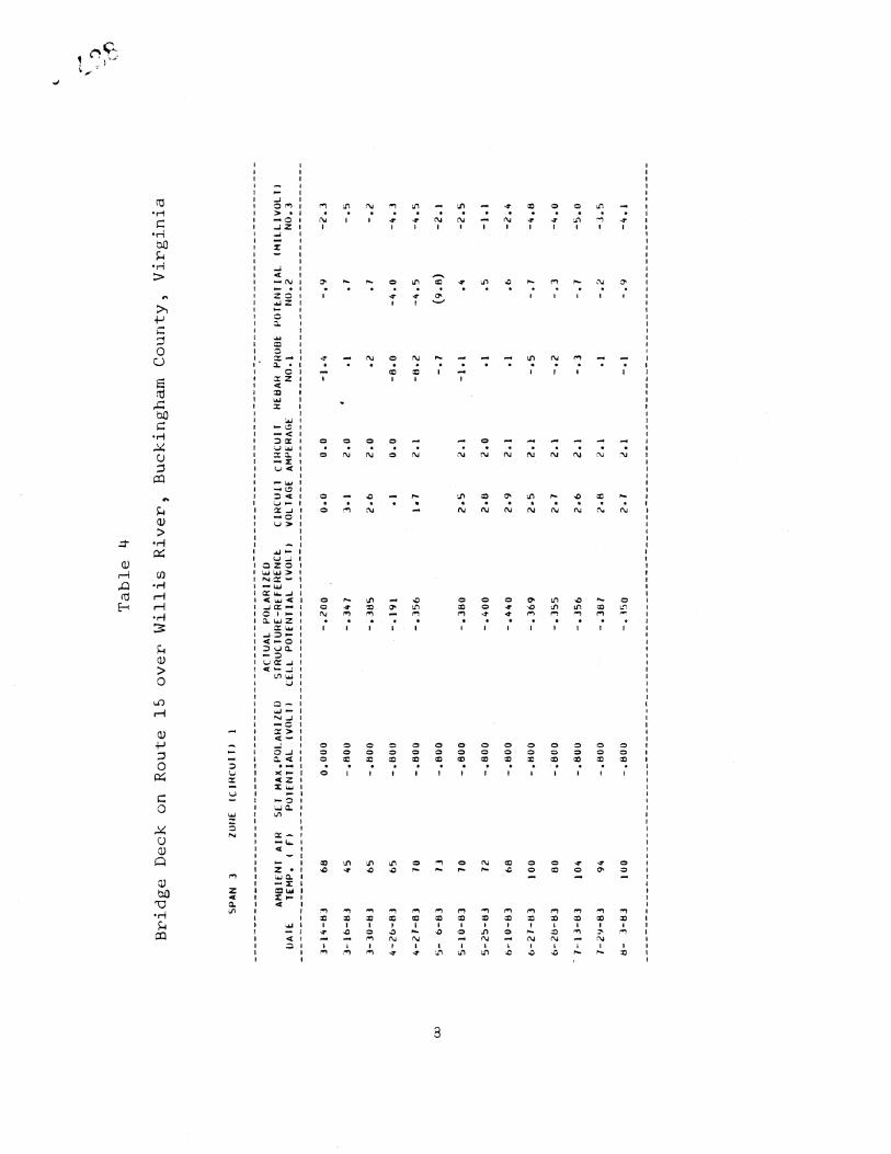
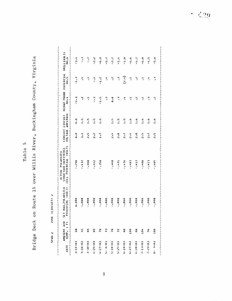
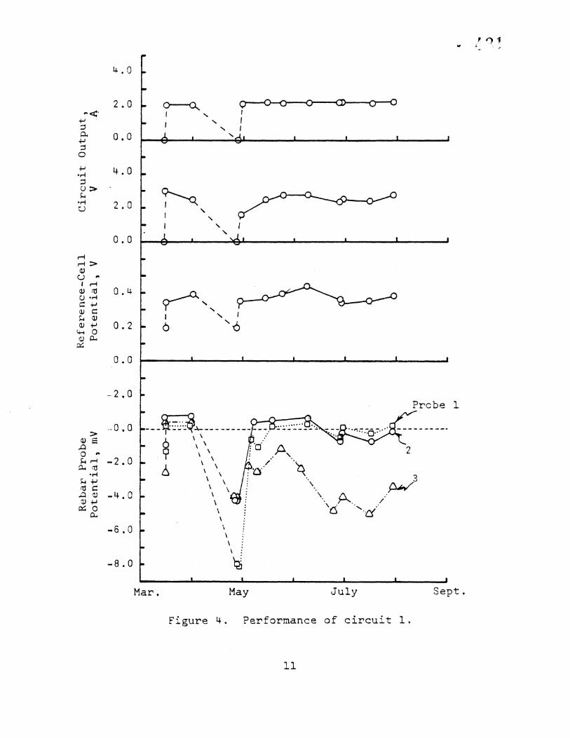
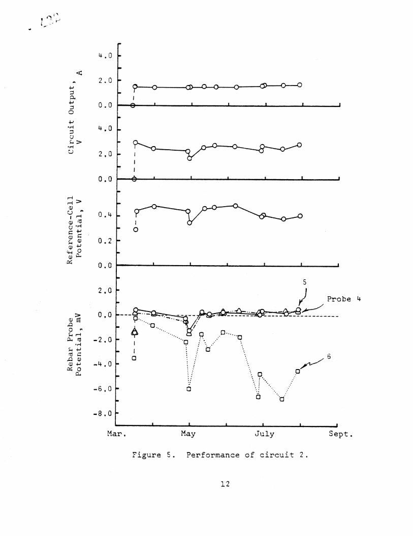
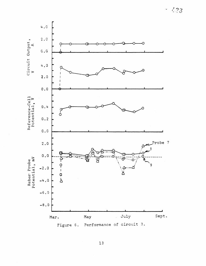
Since the whole cathodic weeks. During reference cell p or circuit, and presented in Tab on April 26, cir blown secondary • uses restored o
very severe thun area caused this
final adjustments protection system each inspection, t otential, and feb temperature have les 4-6 and Figur cult i was found fuses protecting
of the R/C unit on March !6, the has been inspected almost every 2 he electrical output, structure- ar probe potentials in each zone, been measured These read'ngs are
es 4-7. !t should be noted that to be inoperative, as i.ndicated by the circuit. Replacement of these
peration of the circuit. It is speculated that a derstorm reported to have occurred in the general temporary shutdown.
; g g
0
0
0
0
0
0
0
.,-!
ZO
4.0
2.0
-2.0
-2.0
-4.0
-6.0
-8.0
\
Prc be I
3
Mar. May July Sept.
Figure 4. Pemfommance of circuit I,
2.(]
f••. o.o
0 •q -•..o ,M
•-• -•,0 • 0
-8.0
Mal
,| ..1
May July
Probe
Sept.
Figure 5. Performance of circuit 2.
12
• 0
O,CI
-6.0
-8.0
_1
Probe
\
Mare. May July Sept.
Figume 6. Pemfommance of cimcuit 3.
13
120
I00
4O
2O
May July Sept.
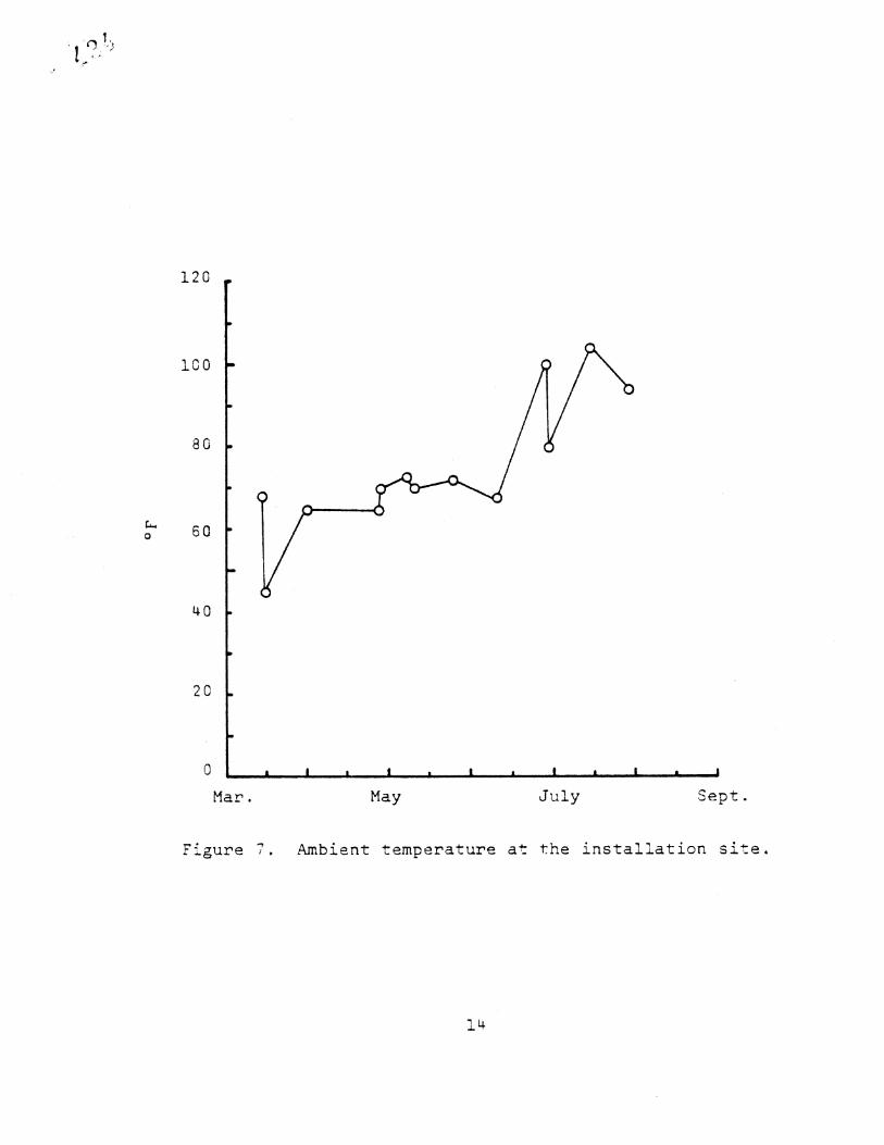
Figure •. •bient temperature at the installation site.
14
In addition, on May 6 the LCD meter in •he R/C unit was found to be defective. A faulty circuit board for the meter was found •o be the cause and was repaired by Good-All, under warranty. Be- fore the repair was done, the various readings normally provided by the meter were measured with a portable digital mu!timeter. •evertheless, the data collected so far have indicated that the cathodic protection system is functioning as expected. Since the chosen mode of operation of the R/C unit is constant current, the unit has been maintaining the current level it is set to provide to each span, as illustrated in Figures 4 through 6. It can be observed that the extreme high temperatures and lack of precipita- tion experienced this summer have led to temporary anodic shifts in the structure-rebar probe potentials. The shifts for probe 3 in span 3 and probe 6 in span 2 were particularly large. These shifts were caused by increased resistivity of the concrete brought about by the absence of moisture. Fortunately, corrosion activity typically is extremely slow, or nil, under this condition.
Lastly, the conductive polymer concrete used in the slots appears to be holding properly.
CONCLUSION
The cost of this particular CP system, which is approximately $179.3/m 2 ($16.67/ft.2), probably does not serve as a good guide for what similar installations might cost. Because this was the first such installation in the state, it is believed that the bidders built-in an appreciable cushion to protect themselves against the un- expected. In addition, there were some costs, such as that for the R/C unit and start-up of construction, that would be essentially the same regardless of the size of the deck. For a larger deck, such costs would mean relatively smaller costs per unit area.
The design and installation of such a system is very straight- forward, so that installation by state force to reduce cost is an alternative that might be considered.
The data collected so far indicate that this whole CP system is functioning proper!y{ although it may be possible that the leve!• of protective current applied to some areas in spans 2 and 3 aren't =uffic•ent- and need to be increased. I+. is believed t•.a•h it is best_ to continue observing the behavior of the system until it is a year old before making a decision regarding this matter.
15