Embed Size (px)
Citation preview
METHODS FOR INCREASING THE HARSHNESS OF TEXTURE ON OLD CONCRETE I•AVEMENTS
--Mechanical Alteration with the Klarcrete Machine--
by
Marion F. Creech Highway Materials .Research Analyst
Virginia Highway Research Council (A Cooperative Organization Sponsored Jointly by the Virginia
Department of Highways and the University of Virginia)
Charlottesville• Virginia
August 1973
VHRC 73-R8

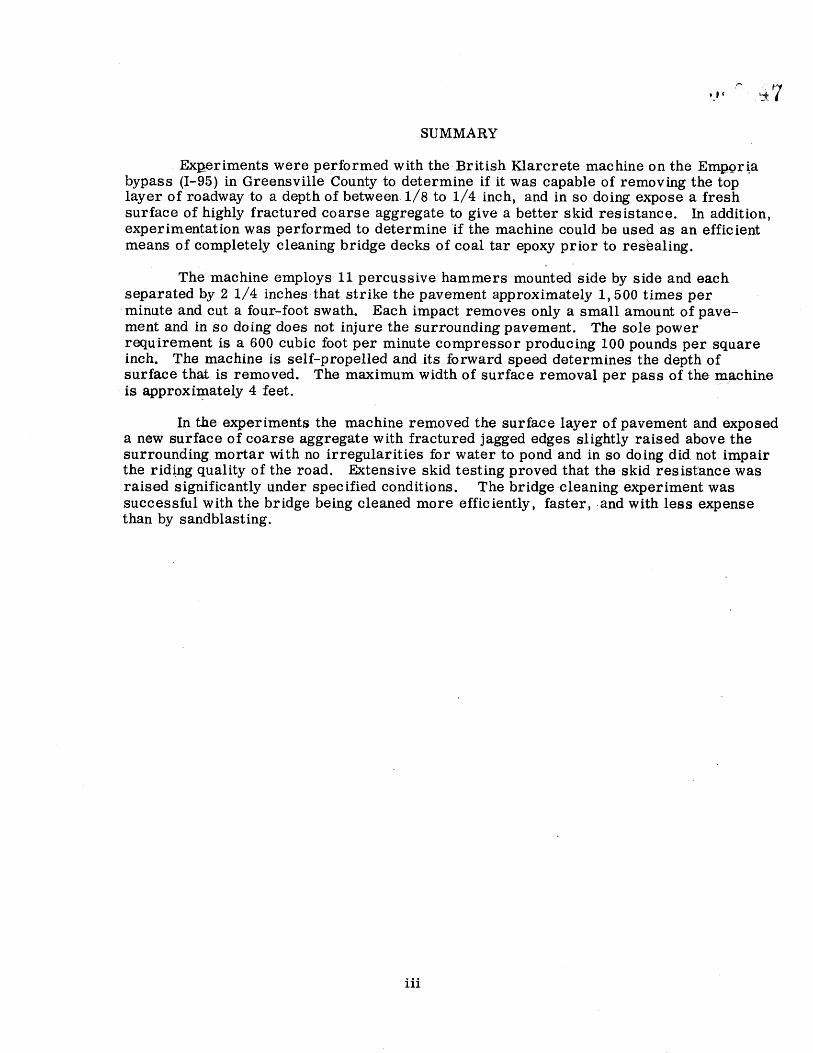
SUMMARY
Ext•eriments were performed with the British Klarcrete •machine-on the Emt•_ori.a bypass (I-95) in Greensville County to determine if it was capable of removing the top layer of roadway •to a depth of between. 1/8 to 1/4 inch, and in so doing expose a fresh surface of highly fractured coarse aggregate to give a better skid resistance. In addition, experimentation was performed to determine if the machine could be used as an efficient means of completely cleaning bridge decks of coal tar epoxy prior to res•aling.
The machine employs 11 percussive hammers mounted side by side and each separatedby 2 1/4 inches that strike the pavement approximately 1,500 times per .minute and cut a four-foot swath. Each impact removes only a small amount of pave- ment and in so doing does not injure the surrounding pavement. The sole power requirement is a 600 cubic foot per minute compressor producing 100 pounds per square inch. The machine is self-propelled and its forward speed determines the depth of surface that is removed. The maximum width of surface removal per pass of the machine is ,approximately 4 feet.
In the experiments the machine removed the surface layer of pavement and exposed a new surface of coarse aggregate with fractured jagged edges slightly raised above the surrounding mortar with no irregularities for water to pond and in so doing did not impair the ridi.ng quality of the road. Extensive skid testing proved that the•skid resistance was raised significantly under specified conditions. The bridge cleaning experiment was successful with the bridge being cleaned more efficiently, faster, ,and with less expense than by sandblasting.
iii

METHODS FOR INCREASING THE HARSHNESS OF TEXTURE ON OLD CONCRETE PAVEMENTS
--Mechanical Alteration with the Klarcrete Machine--
by
Marion F. Creech Highway Materials Research Analyst
INTRODUCTION
The experiments reported here were conducted as part of an evaluation of available methods of increasing the harshness of texture of old concrete pavements° Included among the methods to be evaluated in the overall study are those that are presently used such as grooving and sandblasting• but the real emphasis is to discover new and better methods of roughening the pavement° It probably is not necessary to recount here the reasons for the efforts being expended in search of better ways of increasing the texture of concrete pavements° A brief statement to the effect that concrete pavements have been proved to approach a slippery condition when wet after 20 to 25 million vehicles passes(1) will suffice when coupled with the fact that many concrete pavements relatively recently put into service are approaching that accumulated volume. Even long before this type pavement becomes slippery as measured by conventional methods the surface becomes smooth• which when coupled with the inability of portland cement concrete to allow water to penetrate the surface, even under pressure• provides an ideal condition for hydroplaning under specified water• tire tread depth• and velocity conditions°
One of the avenues of investigation emphasized in the working plan for the study was the mechanical alteration of pavements° (2) It was contemplated that the exploration of this avenue would include a search for new machines that would physically remove part of the pavement surface through abrasion or other methods in such a manner as to leave a slightly uneven and nonpolished new surface.
I.n pursuing this avenue o• investigation• it was learned that a British Company•
Klarcrete Ltdo developed a machine for treating concrete pavements and it was obtained on a rental basis for a pilot study:
THE KLARCRETE MACHINE
General
The Klarcrete general purpose concrete repair machine removes the pavement surface by employing 11 percussive hammers that operate independently and each strike the pavement approximately 1• 500 times per minute° The machine operates on
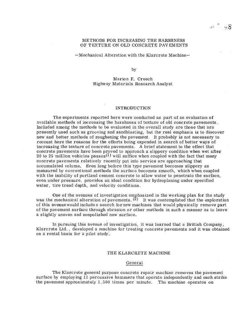
compressed air and requires at least a 600 cubic foot per minute compressor capable of producing 100 pounds of compressed air per square inch. The hammers are 2 1/4 inches in diameter and are 2 1/4 inches apart. They are mounted on a carriage that allows vertical movement and which in turn is attached to a transverse carriage that allows lateral movement. The lateral movement is necessary to get uniform removal of concrete over the width of operation. The width of cut is variable from 4 1/2 inches [ 2 1/4 inches (diameter of cutting head) + 2 1/4 inches (space between cutting heads) 4 1/2 inches] to 49 1/2 inches in 4 1/2 inch increments by adding or deleting individual cutting heads. Figure 1 gives the configuration of the cutting heads. The cutting heads, which require no lubrication and are free to rotate, break the concrete into small particles of a gradation not much larger than dust and cause no damage to the surrounding concrete. When standing on the pavement beside the machine while it is in operation one
can notice the vibrations but they are not great. The machine removes the surface by the number of impacts rather than the force of individual impacts. When the object is to remove the top surface of the concrete in a continuous sweep the machine travels slowly forward under its own power. The depth of removal of concrete is dependent upon the forward speed of the machine. A small pneumatic motor attached to the left rear wheel allows automatic operation and permits the towing of a compressor power source.
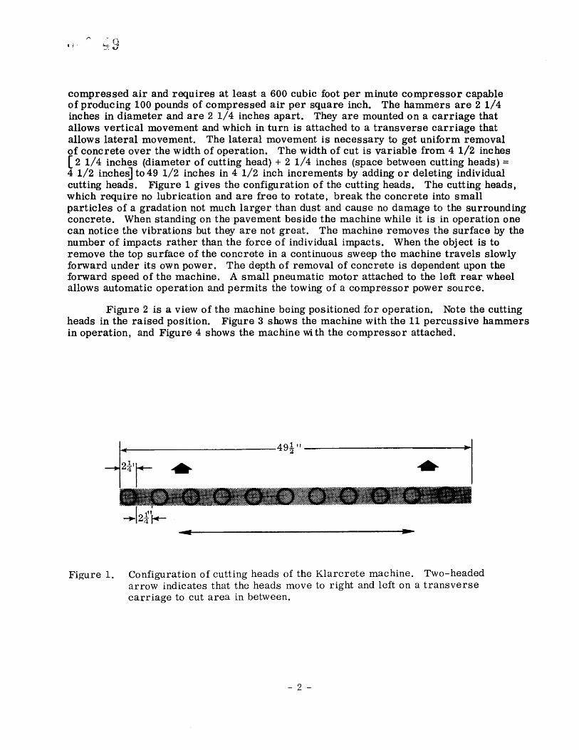
Figure 2 is a view of the machine being positioned for operation. Note the cutting heads in the raised position. Figure 3 shows the machine with the 11 percussive hammers in operation, and Figure 4 shows the machine with the compressor attached.
Figure I. Configuration of cutting heads of the Klarcrete machine. Two-headed
arrow indicates that the heads move to right and left on a transverse carriage to cut area in between.
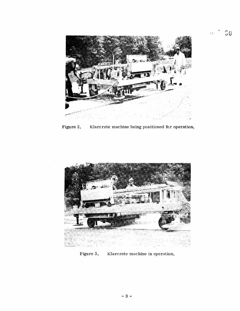
Figure 2. Klarcrete machine being positioned for operation.
Figure 3. Klarcrete machine in operation.
-3-
•Figure 4. Full view of Klarcrete machine and compressor.
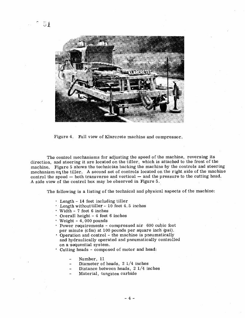
The control mechanisms for adjusting the speed of the machine, reversing its direction, and steering it are.located on the tiller, which is attached to the front of the machine. Figure 5 shows the technician backing the machine by the controls and steering mechanism or•the tiller. A second set of controls located on the right, side of the machine control the speed both transverse and vertical and the pressure to the cutting head. A side view of the control box .may be observed in Figure 5.
The following is a listing of the technical and physical.aspects of the machine:
Length- 14 feet including tiller Length without tiller 10 feet 4.5 inches Width- 7 feet 6 inches Overall height 4 feet 6 inches Weight 4,000 pounds Power requirements compressed air 600 cubic foot per minute (cfm) at 100 pounds per square inch (psi). Operation and control the machine is pneumatically and hydraulically operated and pneumatically controlled on a .sequential system. Cutting heads composed of motor and head:
Number, 11 •Diameter of heads, 2 1/4 inches Distance between heads, 2 1/4 inches Material, tungsten carbide
-4-
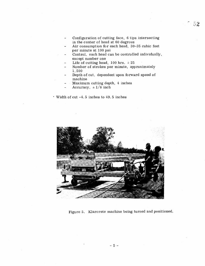
Configuration of cutting facet 6 tips intersecting in the center of head at 60 degrees Air consumption for each head• 30-35 cubic feet per minute at 100 psi Control• each head can be controlled individually, except number one Life of cutting head• 100 hrso • 25 Number of strokes per minute, approximately 1,500 Depth of cut9 dependent upon .forward speed of machine Maximum cutting depth• 4 inches Accuracy, ± 1/8 inch
Width of cut -4° 5 inches to 49° 5 inches
Figure 5o Klarcrete machine being, turned and positioned°
-5-
PURPOSE
This project was initiated to determine the Klarcrete machine's ability to
remove the surface layer of concrete to an approximate depth of 1/4 inch and in so
doing chip and fracture the aggregate (in this case granite) to give fresh, sharp edges protruding slightly above the surrounding mortar. This should provide better skid resistance and help prevent hydroplaning. A second purposes the determination of whether the Klarcrete machine could be used to effectively clean bridges of hard to
remove substances such as coal tar epoxy• was •idded after the projec.t was initiated. Cost data were developed to afford comparisons-with other methods of texturing and bridge cleaning. Also of importance was the speed at which the machine accomplished its task, since the less time spent on high traffic volume highways, the better.
TEST SITES
After establishing the availability of the machine• a search was begu.n for suitable sites for the experiments°
In planning the experiments to remove the pavement surface,• some of the characteristics thought important for thesite to possess were: (1) the portland cement concrete should be constructed with nonpolishing aggregate; (2) the road should carry high traffic volumes; and (3) the road must be old enough to have high accumulated volumes. In addition• it was desirable to have a site that had been tested and adjudged slippery• that is• one with a skid number less than 40. The site selected was not the first choice• since the skid number was approximately 50 and the traffic volume was not extremely high (13• 240 average daily traffic) but more
desirable locations were .not available for experimentation for a variety of reasons.
The site is in the southbound direction of 1-95 on the Emporia Bypass in Greensville County beginning 0o 11 mile south of Rt. 611 at milepost 9o 82 and ending• 0.14 mile .north of Rto 611 at milepost 10.07. The portland cement concrete pave- ment• constructed in 1959 of nonpolishing aggregate (granite)• is nine inches thick and consists of 25 and 50 foot slabs° While the site was not the best suited one for the experiment• it was entirely adequate for determining the question of whether the machine w•uld uniformly remove the surface and at the same time fracture the large aggregate so as to raise the skid values°
The bridges selected to test the machine's ability to clean coal tar epoxy from the decks are over the Meherrin River in both the northbound and southbound directions of 1-95 0.4 mile .north of the pavement surface removal experiment between mileposts 10.52 and 10o 62. The bridges are approximately 530 feet long.
-6-
EXPERIMENTS PERFORMED WITH THE KLARCRETE ,MACHINE
Removal of Road Surface
The first experiment performed with the Klarcrete machine was an operation referred to as mass area bush hammering• a process by which the entire surface of the roadway is removed to a desired depth leaving exposed fresh highly fractured aggregate slightly raised above the surrounding portland cement mortar. A one-fourth mile section of 2_.4 foot pavement was bush hammered at the previously noted site. From 1/8 to 1/4 inch of surface was removed. The operation was begun on May 14• 1973 and completed May 24• 1973o The time of machine operation was 46 hours and42 minutes. Each machine pass covered approximately four feet; six passes were required to treat the entire width of pavement° The total area treated was 30• 934 square feet and the average area treated per hour was 680 square feet. The forward motion of the machine per hour was 170 feet.
Removal of Coal Tar Epoxy from t•ridge Decks
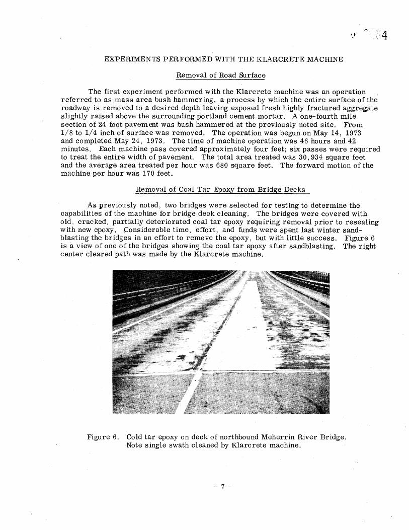
As lpreviously noted• two bridges were selected for testing to determine the capabilities of the machine for bridge deck cleaning. The bridges were covered with old• cracked• partially deteriorated coal tar epoxy requiring removal prior to resealing with new epoxy. Considerable time• effort• and funds were spent last winter sand- blasting the bridges in an effort to remove the epoxy,• but with little success. Figure 6 is a view of one of the bridges showing the coal tar epoxy after sandblasting. The right center cleared path was made by the Klarcrete machine.
Figure 6o Cold tar epoxy on deck of northbound Meherrin River Bridge° Note single swath cleaned by Klarcrete machine.
-7-
Officials of the Suffolk District office• after observing the machine in operation• wished to rent it in an attempt to remove the old epoxy fromthe bridges° The bridge cleaning operation• which was the same type operation as bush hammering except for
a different purpose and removal of different materials• began May 30 and was completed June 21o, Time required to clean the southbound bridge was 36 hours and 50 minutes for
an average of 348 square feet per hour° For the northbound bridge• the cleaning time was 49 hours and 54 minutes for an average of 240 square feet per hour° Progress on
the northbound bridge was slower due to the greater amou.nt of previous sandblasting on
the southbound bridge and therefore less epoxy. As may be seen• progress on both bridges was considerably slower than the 670 square feet per hour o.n the road° This is explainable by comparison of the different types of material that the machine was removing. The harder and more brittle a surface the easier it is to fracture and the more effective the operation of the Klarcrete machine becomes• since it functions by hammering the pavement surface into small particles° The road surface was hard and brittle and the machine operated efficiently on it but the resilence of the coal tar epoxy slowed operations on the bridges° In fact it has been reported that attempts at removing bituminous overlays have not been very successful° However the problem in Virginia is not removing bituminous overlays from bridges• which can be done rather easily with a heater planer• but cleaning the bridges after the overlays have been removed°
PROBLEMS ENCOUNTERED DURING EXPERIMENT
Klarcrete Machine
With regard to maintenance the Klarcrete machine performed creditably; minor problems did,• however• arise in the form of broken air hoses° The average time for replacing a hose was 15 minutes° With sufficient hoses on hand replacement was not a
greatproblem and could be reduced by inspection and replacement where cracking of the hoses occursprior to operation° The cutting heads were replaced once during the experiments but the time required was not prohibitive°
Compressor
The major equipment malfunction occurring during the entire experiment involved the 600 cfm compressor necessary to operate the machine° Four different
compressors were used during the job and each needed extensive repairs that necessitated long periods of downtime. The bush hammering of the road surface required nine working days but the machine was in operation only 46 hours and 42 minutes. Over 90 percent of the downtime was attributable to compressor malfunction. For cleaning the southbound bridge• 36 hours and 50 minutes of machine time was
necessary; however• the machine was inoperable 20 hours and 20 minutes due to
compressor failure. In summary• malfunctioning of the compressors approximately doubled the time necessary for doing the job. A large compressor might do a better job since the air requirements of the,iKlarcrete machine are so great that the 600 cfm
compressors may have had difficulty'sustaining production of the necessary air.
-8-
Regardless of the cause of compressor failure• the contractor should be required to guarantee a workable one since additional unwarranted time spent on
a high volume road increases the chances of accident to all involved• increases the cost for traffic control personnel (who often have other assigned tasks)• and incon- veniences the traveling public°
Noise and Air Pollution
Operation of the Klarcrete machine produced a noise level that was uncom-
fortable to persons in its immediate vicinity° For this reason• all machine operators should wear ear protection° No equipment was
available for measuring machine noise• but since no citizens complained it must be assumed that the noise was absorbed by the environment to the degree that it was not an undue nuisance° It should be noted that although a small town was nearby• the area is rural in nature and that some means of muffling the noise might be necessary in a metropolitan area and/or for night work.
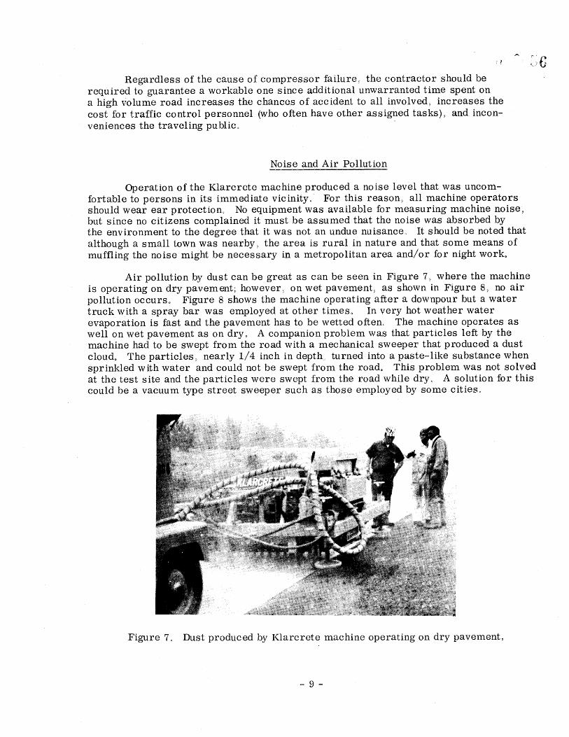
Air pollution by dust can be great as can be seen in Figure 7• where the machine is operating on dry pavement; however• on wet pavement• as shown in Figure 8• no air pollution occurs° Figure 8 shows the machine operating after a downpour but a water truck with a spray bar was employed at other times° In very hot weather water
evaporation is fast and the pavement has to be wetted often° The machine operates as
well on wet pavement as on dry° A companion problem was that particles left by the machine had to be swept from the road with a mechanical sweeper that produced a dust cloud. The particles• nearly 1/4 inch in depth turned into a paste-like substance when sprinkled with water and could not be swept from the road° This problem was not solved at the test site and the particles were swept from the road while dry° A solution for this could be a vacuum type street sweeper such as those employed by some cities°
Figure 7o Dust produced by Klarcrete machine operating on dry pavement°
-9-
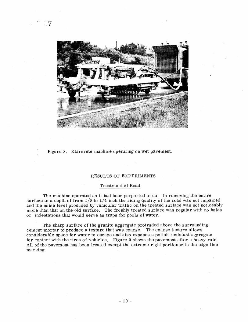
Figure 8. Klarcrete machine operating on wet pavement.
RESULTS OF EXPERIMENTS
Treatment of Road
The machine operated as it had been purported to do. In removing the entire surface to a depth of from 1/8 to 1/4 inch the riding quality of the road was not impaired and the noise level produced by vehicular traffic on the treated surface was not noticeably more than that on the old surface. The freshly treated surface was regular with no holes or indeatations that would serve as traps for pools of water.
The sharp surface of the granite aggregate protruded above the surrounding cement mortar to produce a texture that was coarse. The coarse texture allows considerable space for water to escape and also exposes a polish resistant aggregate for contact with the tires ofvehicleso Figure 9 shows the pavement after a heavy rain° All of the pavement has been treated except the extreme right portion with the edge line marking.
-10-
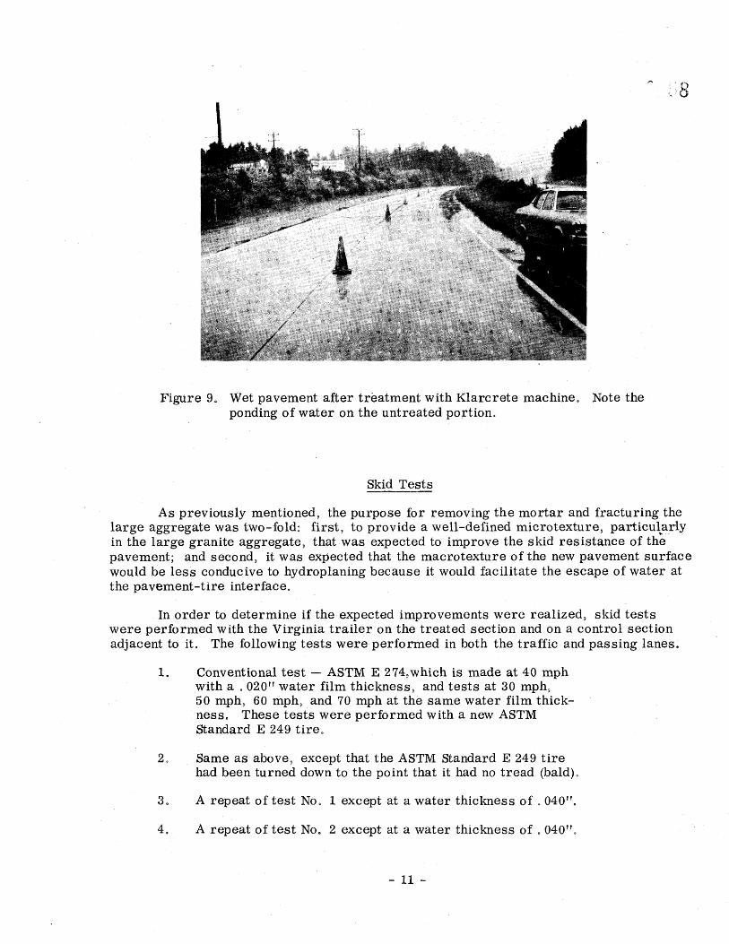
Figure 9. Wet pavement after treatment with Klarcrete machine. Note the ponding of water on the untreated portion.
Skid Tests
As previously mentioned, the purpose for removing the mortar and fracturing the large aggregate was two-fold: first• to provide a well-defined microtexture• particul.arly in the large granite aggregate• that•was expected to improve the skid resistance of the pavement; and second• it was expected that the macrotexture of the new pavement surface would be less conducive to hydroplaning because it would facilitate the escape of water at the pavement-tire interface.
In order to determine if the expected improvements were realized• skid tests were performed with the Virginia trailer on the treated section and on a control section adjacent to ito The following tests were performed in both the traffic and passing lanes0
Conventional test ASTM E 274,which is made at 40 mph with a 02.0" water film thickness• and tests at 30 mph• 50 mph• 60 mph• and 70 mph at the same water film thick- ness. These tests were performed with a new ASTM Standard E 249 tire.
Same as above.• except that the ASTM Standard I• 249 tire had been turned down to the point that it had no tread (bald)o
repeat of test No° 1 except at a water thickness of 040".
4. A repeat of test No. 2 except at a water thickness of 040"°
11
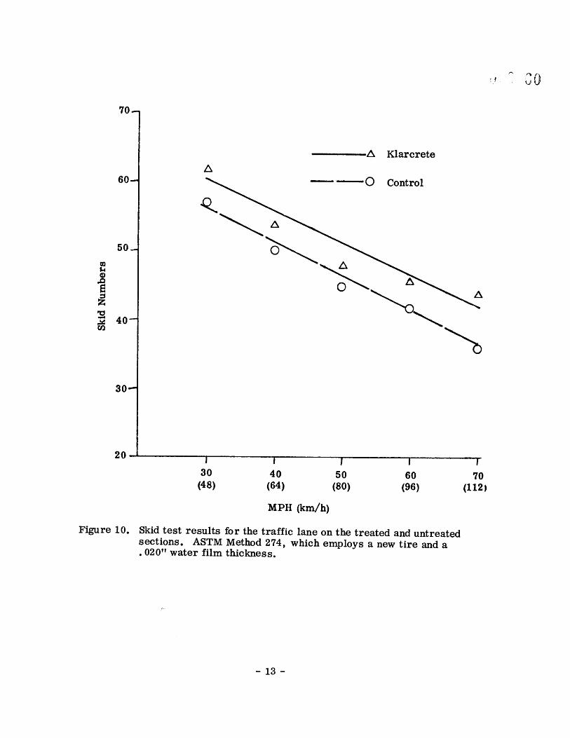
Figures 10 through 19 present the data in numerical and graphic form, Each value is the average of five tests,
Figure 10 shows that the pavement not only had very good skid resistance before treatment when tested by ASTM Method E 274• but also had an acceptable skid number at 70 mpho Even so the Klarcrete treatment improved the skid number by about four units
up through 60 mph and by about eight skid numbers at 70 mpho If tests were performed at 40 mph only• it would be questionable if the increase in skid number from 50 to 54 would justify the expense of the treatment, However• the increase of eight skid numbers• from •6 to 44• at 70 mph would justify the treatment if the site had a high wet accident history, Both curves in Figure 10 depict only a moderate loss in skid resistance with increased speed• which indicated no tendency toward hydroplaning°
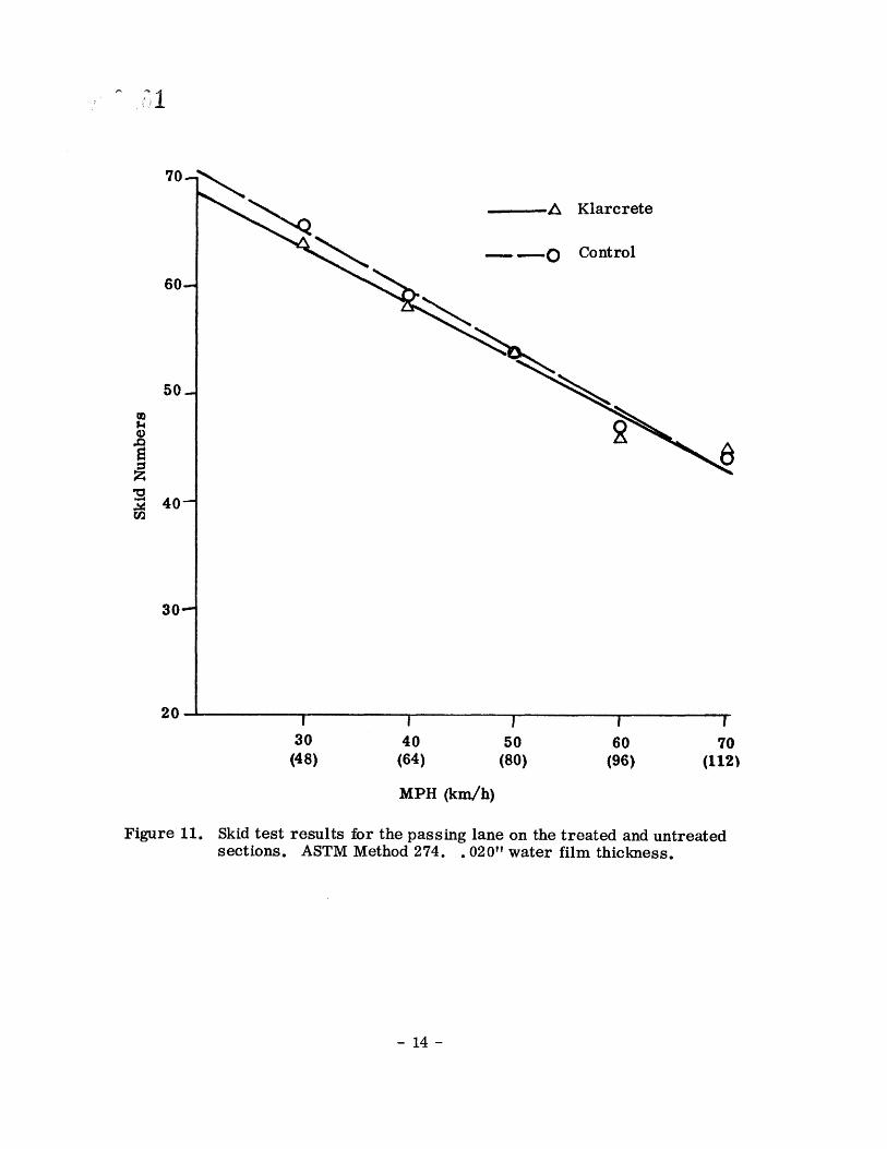
Figure 11• like Figure 10g reflects data gathered by ASTM Method E 274• but for the passing lane as opposed to traffic laneo This lane had received less traffie• and it can be seen that no improvement was realizedo
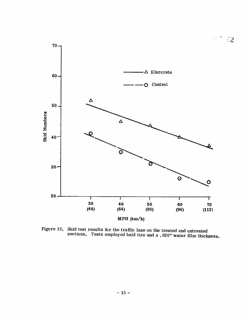
Figure 129 shows results on the traffic lane• with the bald E 249 tire° The improvement in skid resistance is significant• even at the low speed of 30 mph• where the treatment caused an increase of 11 skid numbers° Since the curves are parallel and neither approaches zero.• there is still no indication of absolute hydroplaning• although it is obvious that the channels in the pavement surface effectively provide for the escape of water when a bald tire is in use,
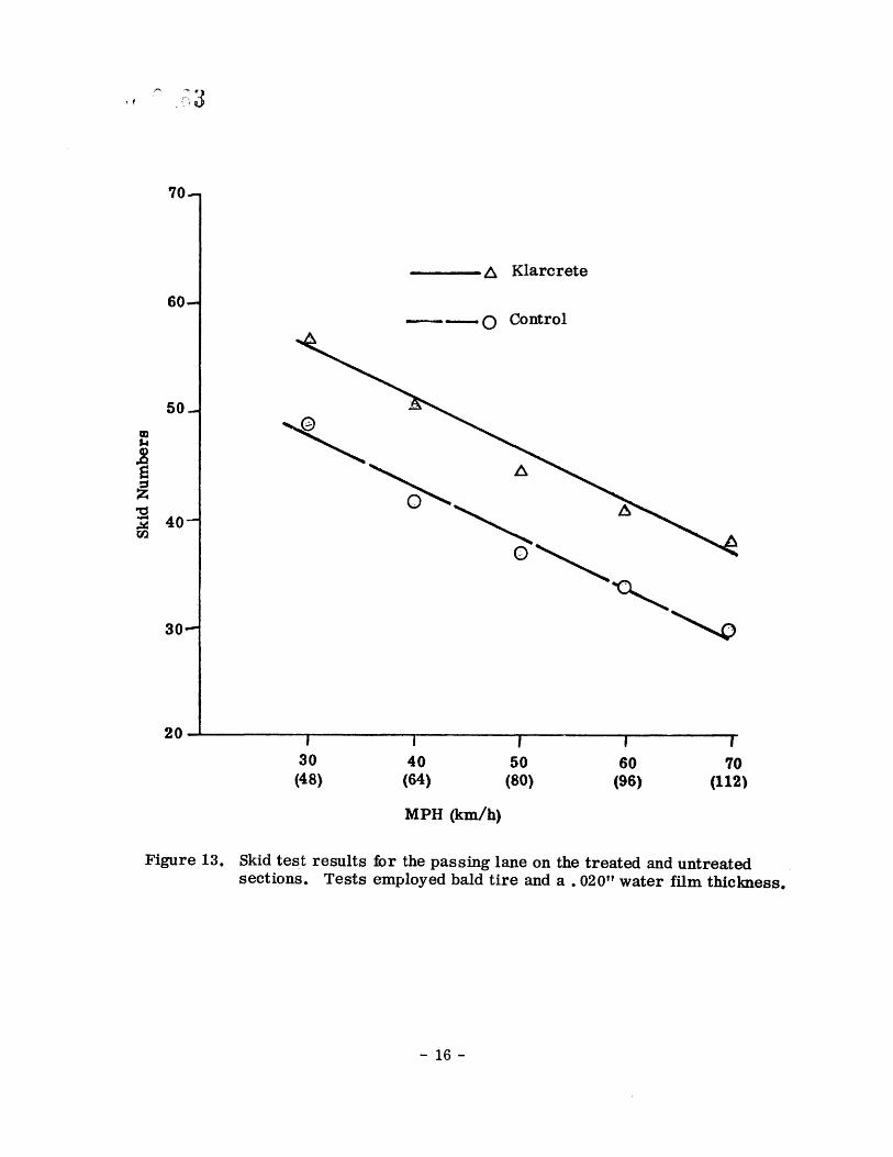
In Figure 13• which shows results of the bald tire tests in the passing lane• two things should be noted° First• there is a smaller increase in the skid number as
a result of treatment than there was in the traffic lane (8 SN as Compared to 11 SN); and second• the skid number before treatment is about 6 SN higher than that in the traffic lane before treatment. The latter fact indicates that the "texture in the passing lane prior to treatment• although it was very fine and would probably be classi.fied as microtexture• did provide for enough contact with the bald tire to generate skid values which would satisfy any minimum requirements with which the author is familiar°
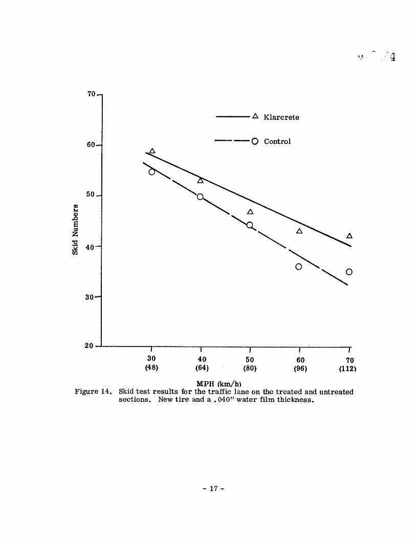
All skid data reported graphically thus far resulted from tests performed with a water film thickness of 020"° The results shown in Figures 14.• 15.• 16• and17 were obtained at a water film thickness of 040",
The values in Figure 14• obtained in the traffic lane with a new tire• are essentially the same as those shown in Figure 10• which were recorded in tests on half the water film thickness, This finding indiates two things: first• a film thickness of ,040 •' is not enough water to overtax a new ASTM tire; and second• for realistic testing• the 020" film thickness prescribed by ASTM is sufficient°
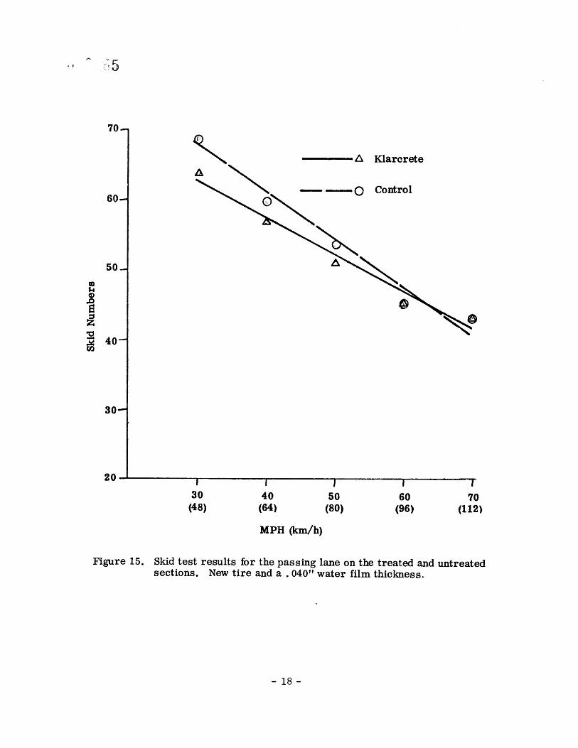
Figure 15 shows the skid values obtained on the passing lane with the new test tire and a film thickness of 040•'o Remember that in Figure 11• which showed tests with the same tire but half the amount of water• some values were higher for the untreated pavement than for the treated° Figure 15 reveals the same phenomenon• which is accepted as insignificant or as a testing error due to the small amount of data° However• it could well be that a reduction in surface area under some conditions could reduce skid numbers.
12-
70.-
60--
30
20,
Figure 10.
z• Klarcrete
•O Control
30 40 50 60 •'0 (48) (64) (80) (96) (112•
MlaH (kin/h)
Skid test results for the traffic lane on the treated and untreated sections. ASTM Method 274, which employs a new tire and a .020" water film thickness.
13
-• Klarcrete
••,• ----O Control
60-- •
40-
30--
20
Figure II.
30 40 50 60 70 (48) (64) (80) (96) (112•
MPH (km/h)
Skid test results for the passing lane on the treated and untreated sections. ASTM Method 274. .020" water film thickness.
14
70-
60--
50--
40-
30--
20
Figure 12.
A Klarcrete
0 Control
! 30 40 50 60 70 (48) {64) (80) (96• (1121
MPH (km/h)
Skid test results for the traffic lane on the treated and untreated sections. Tests employed bald tire and a. 020" water film thickness.
15-
70.-
60.-
50-
4o-
30--
A Klarcrete
0 Control
30 40 50 60 70 (48) (64) (80) (96) (112•
MPH (km/h)
Figure 13. Skid test results for the passing lane on the treated and untreated sections. Tests employed bald tire and a. 020" water film thickness.
16-
70--
60--
50.-
40--
30--
20.
Figure 14.
A Klarcrete
30 40 50 60 70 (48) (64) (80) (96) (112)
MPH (km/h• Skid test results for the traffic lane on the treated and untreated sections. New tire and a. 040" water film thickness.
17-
70.-
60--
30
20
Klarcrete
Control
! 30 40 50 60 70 (48) (64) (80) (96) (112)
MPH (km•h)
Figure 15. Skid test results for the passing lane on the treated and untreated sections. New tire and a. 040 '• water film thickness.
18-
70--
60--
50.-
40-
30
20-
Figu re 16.
A Klarcrete
O Control
30 40 50 60 70 (48) (64) (80) (96) (1
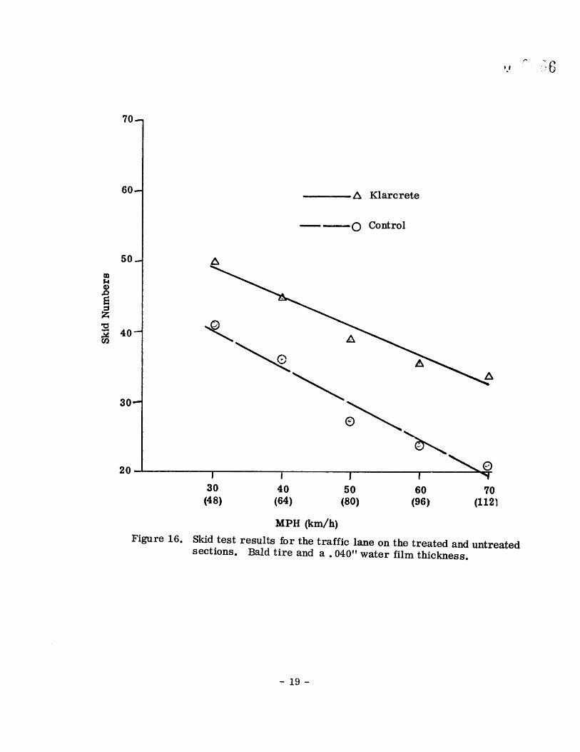
MPH (km/h) Skid test results for the traffic lane on the treated and untreated sections. Bald tire and a. 040" water film thickness.
19-
70--
60--
50-
40
30--
20L
z• Klarcrete
0 Control
30 40 50 60 "/0 (48) (64) (80) (96) (112)
MPH (kin/h)
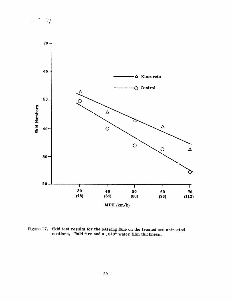
Figure 17. Skid test results for the passing lane on the treated and untreated sections. Bald tire and a. 040 T' water film thickness.
20
70-
40-
20
•, Klarcrete
0 Control
ew 9•/32 7•/32 5•32 3/•32 B•ald
70 MPH 040•Vater
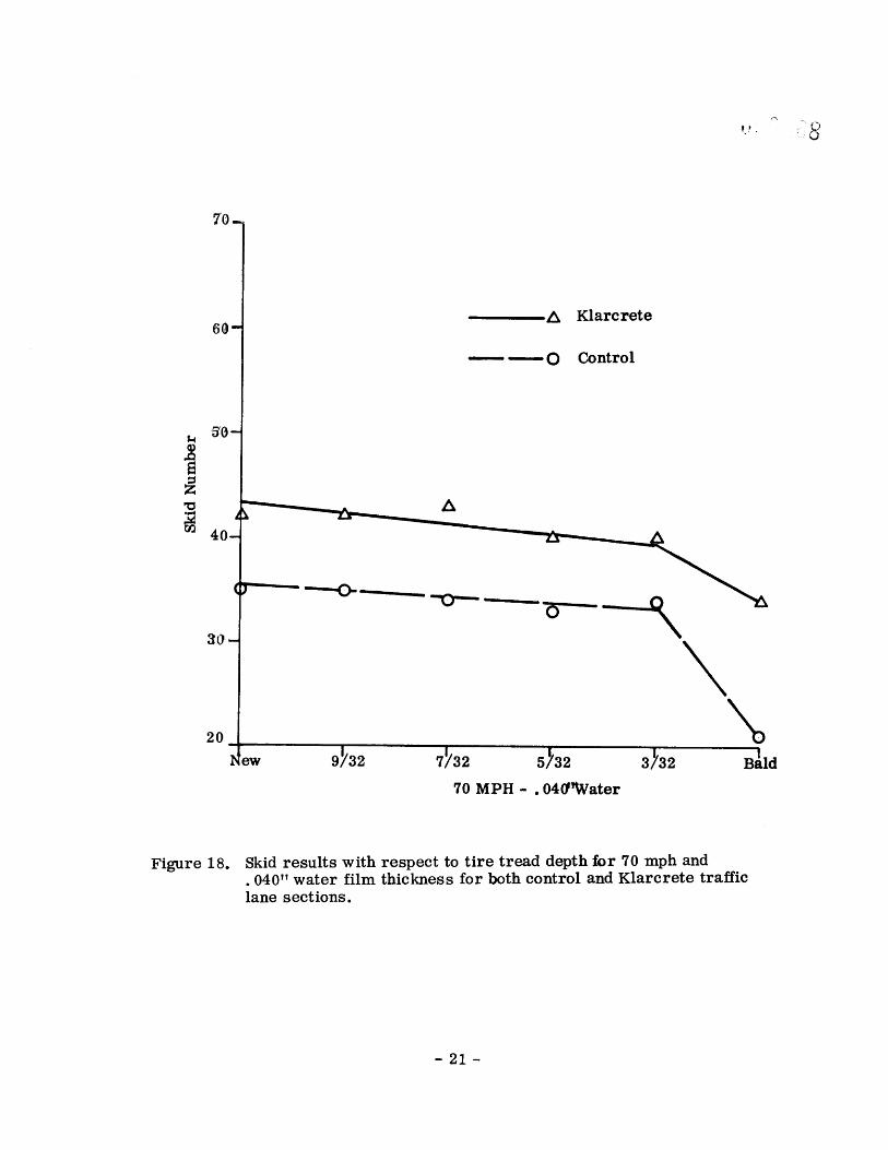
Figure 18. Skid results with respect to tire tread depth for 70 mph and 040" water film thickness for both control and Klarcrete traffic
lane sections.
21-
70-
60-
3O
20 New
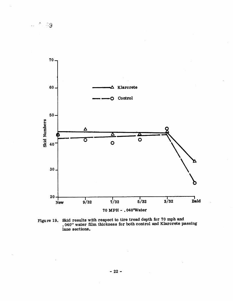
Figure 19.
, • Klarcrete
---'----O Control
0 0 0
Bald
,/0 MPH 040'Water
Skid results with respect to tire tread depth for '/0 mph and .040" water film thickness for both control and Klarcrete passing lane sections.
22
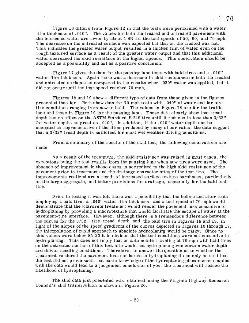
Figure 16 differs from Figure 12 in that the tests were performed with a water film thickness of 040"° The values for both the treated and untreated pavements with_ the increased water are lower by about 4 SN for the test speeds of. 50, 60, and 70 mpho The decrease on the untreated surface was expected but that on the treated was not. This indicates the greater water output resulted in a thicker film of water even on the rough textured surface as a result of the greater water output and that this additional water decreased the skid resistance at the higher speeds. This observation should be accepted as a possibility and not as a positive conclusion.
Figure 17 gives the data for the passing lane tests with bald tires and a. 040" water film thickness. Again there was a decrease in skid resistance on both the treated and untreated surfaces as compared to. the results when 020" water was applied, but it did not occur until the test speed reached 70 mph.
Figures 18 and 19 show a different type of data from those given in the figures presented thus far° Both show data for 70 mph tests with 040" of water and for six tire conditions ranging from new to baldo The values in Figure 18 are for the traffic lane and those in Figure 19 for the passing lane. These data clearly show that tread depth has no affect on the ASTM Standard E 249 tire until it reduces to less than 3/32" for water depths as great as 040". In addition, if the 040" water depth can be accepted as representative of the films produced by many of our rains, the data suggest that a 3/32" tread depth is sufficient for most wet weather driving conditions.
From a summary of the results of the skid test, the following observations are made
As a result of the treatment, the skid resistance was raised in most cases, the exceptions being the test results from the passing lane when new tires were used° The absence of improvement in these cases is accredited to the high skid resistance of the pavement prior to treatment and the drainage characteristics of the test tire° The improvements realized are a result of increased surface texture harshness, particularly on the large aggregate• and better provisions for drainage, especially for the bald test tire°
Prior to testing it was felt there was a possibility that the before and after tests employing a bald tire• a 040" water film thickness, and a test speed of 70 mph would demonstrate that the Klarcrete treatment would render the pavement less conducive to hydroplaning by providing a macrotexture that would facilitate the escape of water at the pavement-tire interface° However, although there¢.is a tremendous difference between the curves for the 3/32" tire tread depth and ,the bald tire in Figures 18 and 19, in light of the slopes of the S•peed gradients of the curves depicted in Figures 10 through 17, the interpolation of rapid approach to absolute hydroplanirg would be risky° Since no skid values were below SN 20 it is obvious that the test conditions.were not conducive to hydroplaning° This does not imply that an automobile traveling at 70 mph with bald tires on the untreated section of this test site would not hydroplane given certain water depth and driverhandling conditions• Therefore• to answer the question as to whether the treatment rendered the pavement less conducive to hydroplaning it can only be said that the test did not prove such, but basic knowledge of the hydroplaning phenomenon coupled with the data would lead to a judgement conclusion of yes, the treatment will reduce the likelihood of hydroplaning.
The skid data just presented was obtained using the Virginia Highway Research Council's skid trailer•which is shown in Figure 20.
23
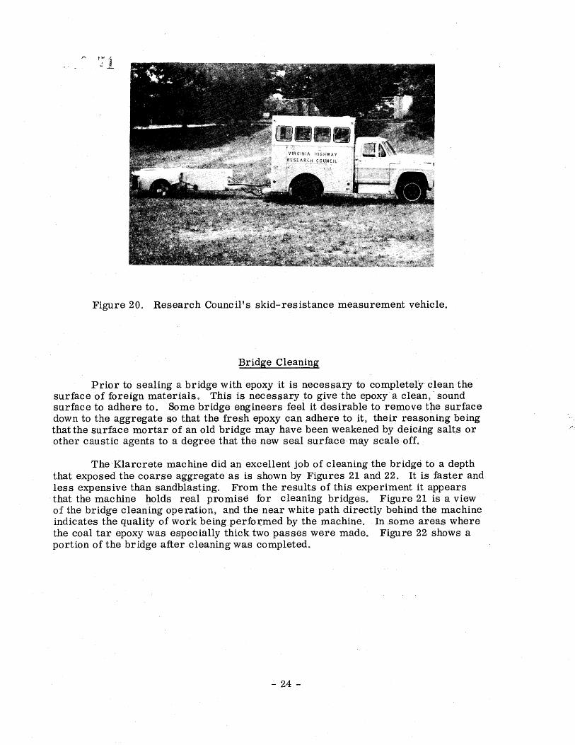
Figure 20. Research Council's skid-resistance measurement vehicle.
Bridge Cleaning
Prior to sealing a bridge with epoxy it is necessary to completely clean the surface of foreign materials. This is necessary .to give the epoxy a clean, sound surface to adhere to. Some bridge engineers feel it desirable to remove the surface down to the aggregate so that the fresh epoxy can adhere to it, their reasoning being that the surface mortar of an old bridge may have been weakened by deic•ing salts or other caustic agents to a degree that the new seal surface may scale-offo
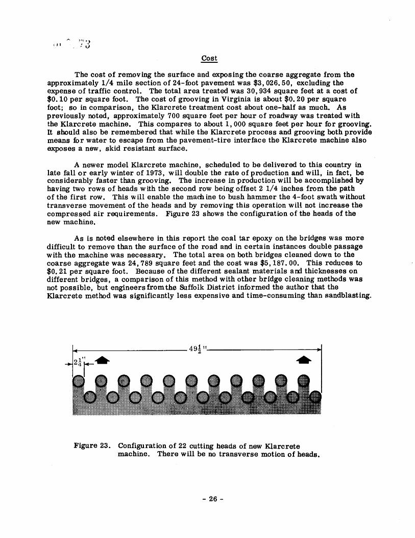
TheKlarcrete machine did an excellent job of cleaning the bridge to a depth that exposed the coarse aggregate as is shown by Figures 21 and 22. It is faster and less expensive than sandblasting. From the results of this experiment it appears that the machine holds real promise for cleaning bridges. Figure 21 is a view of the bridge cleaning operation, and the near white path directly behind the machine indicates the quality of work being performed by the machine. In some areas where the coal tar epoxy was especially thick two passes were made. Figure 22 shows a
portion of the bridge after cleaning was completed.
24
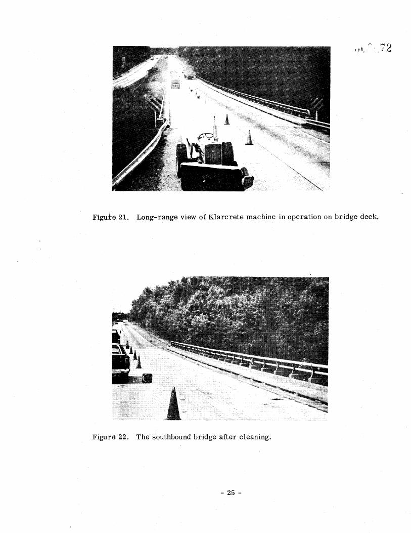
Figure 21. Long-range.view of Klarcrete machine in operation on bridge deck.
Figure 22. The southbound bridge after cleaning°
25
Cost
The cost of removing the surface and exposing the coarse aggregate from the approximately 1/4 mile section of 24-foot pavement was $3,026.50, excluding the expense of traffic control. The total area treated was 30,934 square feet at a cost of $0.10 per square foot. The cost of grooving in Virginia is about $0.20 per square foot; so in comparison, the Klarcrete treatment cost about one-half as much. As previously noted, approximately 700 square feet per hour of roadway was treated with the Klarcrete machine. This compares to about 1,000 square feet per hour for grooving. It should also be remembered that while the Klarcrete process and grooving both provide means for water to escape from the pavement-tire interface the Klarcrete machine also exposes a new, skid resistant surface.
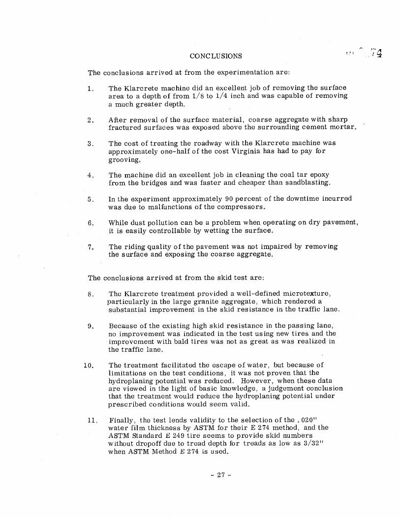
A newer model Klarcrete machine, scheduled to be delivered to this country in late fall or early winter of 1973, will double the rate of production and will, in fact, be considerably faster than grooving. The increase in production will be accomplished by having two rows of heads with the second row being offset 2 1/4 inches from the path of the first row. This will enable the roach ine to bush hammer the 4-foot swath without transverse movement of the heads and by removing this operation will not increase the compressed air requirements. Figure 23 shows the configuration of the heads of the new machine.
As is noted elsewhere in this report the coal tar epoxy on the bridges was more difficult to remove than the surface of the road and in certain instances double passage with the machine was necessary. The total area on both bridges cleaned down to the coarse aggregate was 24,789 square feet and the cost was $5,187.00. This reduces to $0.21 per square foot. Because of the different sealant materials ar•t thicknesses on different bridges, a comparison of this method with other bridge cleaning methods was not possible, but engineers •om the Suffolk District informed the author that the Klarcrete method was significantly less expensive and time-consuming than sandblasting.
Figure 23. Configuration of 22 cutting heads of new Klarcrete machine. There will be no transverse motion of heads.
26
CO NC LU SIONS
The conclusions arrived at from the experimentation are:
1o The Klarcrete machine did an excellent job of removing the surface area to a depth of from 1/8 to 1/4 inch and was capable of removing a much greater depth°
After removal of the surface material• coarse aggregate with sharp fractured surfaces was exposed above the surrounding cement mortar.
The cost of treating the roadway with the Klarcrete machine was
approximately one-half of the cost Virginia has had to pay for grooving.
The machine did an excellent job in cleaning the coal tar epoxy from the bridges and was faster and cheaper than sandblasting.
In the experiment approximately 90 percent of the downtime incurred was due to malfunctions of the compressors.
While dust pollution can be a problem when operating on dry paveme.nt• it is easily controllable by wetting the surface.
The riding quality of the pavement was not impaired by removing the surface and exposing the coarse aggregate.
The conclusions arrived at from the skid test are:
The Klarcrete treatment provided a well-defined microtexture• particularly in the large granite aggregate• which rendered a
substantial improvement in the skid resistance in the traffic laneo
Because of the existing high skid resistance in the passing lane• no improvement was indicated in the test using new tires and the improvement with bald tires was not as great as was realized in the traffic laneo
10o The treatment facilitated the escape of water• but because of limitations on the test conditions• it was not proven that the hydroplaning potential was reduced: However• when these data are viewed in the light of basic knowledge• a judgement conclusion that the treatment would reduce the hydroplaning potential under prescribed conditions would seem valid°
11° Finally• the test lends validity to the selection of the 020" water film thickness by ASTM for their E 274 method• and the ASTM Standard E 249 tire seems to provide skid numbers without dropoff due to tread depth for treads as low as 3/32" when ASTM Method ]• 274 is used°
-27-
RECOMMENDATIONS
As a method of raising the skid resistance on portland cement concrete the Klarcrete treatment should be considered very promising if some or all of the following conditions apply:
(a) The skid resistance is low and the large aggregate in the pavement is considered to be skid resistant°
(b) Pavement has a history of a high rate of wet accidents.
(c) Pavement has water runoff problems.
Therefore it is recommended that the Klarcrete process be employed in addition to grooving on a concrete pavement that merits treatment. This will allow further comparison of the two methods. It would be well if treatment by the two processes abut each other so that they may be compared.
Employ the Klarcrete process on difficult bridge deck cleaning jobs in preparation of sealing since it is more efficient• faster• and less expensive than sandblasting.
Since malfunctioning compressorswere the major cause of delay during the experiments every precaution should be taken to insure that the compressors used in future work are in excellent condition°
In planning for future jobs, consideration should be given to controlling air and noise pollution. Whether pollution will ever be a concern is problematic but the contingency should be considered°
The-Department may wish to consider the purchase of a Klarcrete machine after further observation of its effectiveness since bridge deck maintenance as well as treatment of roads for slipperiness is on the increase. Advantages that would accrue to the Department from the purchase of a machine would be that personnel could be utilized in slack times to clean bridge decks• and slippery areas of pavement could be treated immediately after they are detected.
28-
ACKNOWLEDGEMENTS
The author expresses gratitude to Mr. David C. Mahone, head of the Research Council's Maintenance Section• who was responsible for the collection and analysis of the skid data and author of the section on Skid Tests in this report. He also wishes to thank Mro Mahone for his-interest• enthusiasm• and advice given during the project.
-29-

REF£RENC•S
Io
2•
Mahone David Co• and Stephen No Runkle• "Pavement Friction Needs"• _Highway Research Record 396.• 1972.
Creech• Marion Fo, Working Plan• "Methods for Increasing the Harshness of Texture on Old Concrete Pavements A Pilot Study"• VHRC 72-WP12• Virginia Highway Research Council• November 1972o
31-