Embed Size (px)
Citation preview
8/9/2019 Menvier MF400
http://slidepdf.com/reader/full/menvier-mf400 1/12
PLEASE PASS THIS BOOKLET TO THE USER,AFTER INSTALLATION KEEP WITH PANEL.
MENVIER FIRE SYSTEMMF200/400 MF200-72/400-72
For service Tel:please call:
Service agreement number
1 2 3
1 2 3
4
Z O N E
POWER FAULT
SYSTEM FAU LT
EARTH FAULT
ALARMS
SUPERV ISOR
MODE
DISABLE MOD E
DISABLE TEST
TEST MODE
REMOTE SIGNALDISABLE
POWER
FIRE
FAULT
FAULT
SUPERVISOR MODE SILENCE/SOUND LAMP TEST/EXIT
SILENCE BUZZERRESETSELECT
SUPERVISOR
DISABLE
TEST
M
F 4 0 0
Cooper Lighting and Security Ltd.Wheatley Hall Road, Doncaster, South Yorkshire, DN2 4NB, United Kingdom
Sales General ExportTel: +44 (0)1302 - 303303 +44 (0)1302 - 321541 +44 (0)1302 - 303250
Fax: +44 (0)1302 - 367155 +44 (0)1302 - 303220 +44 (0)1302 - 303251E-mail: [email protected] [email protected] [email protected]
Lighting and Security
PINST MF4/V www.cooper-ls.com
8/9/2019 Menvier MF400
http://slidepdf.com/reader/full/menvier-mf400 2/12
SERVICE SUPPORT NUMBER ......................................................................................................... 1
SYSTEM INFORMATION ...................................................................................................................2PANEL CONTROLS AND INDICATORS ............................................................................................3PANEL OPERATION ...........................................................................................................................4
GENERAL .................................................................................................................................... 4NORMAL OPERATION ................................................................................................................ 4SUPERVISOR MODE ..................................................................................................................4
PANEL INTERFACE CONNECTIONS AND PANEL CONTROLS ...................................................6INPUTS ........................................................................................................................................ 6OUTPUTS .................................................................................................................................... 6
FIRE CONDITION .............................................................................................................................. 6WIRING DIAGRAMS .......................................................................................................................... 7
INSTALLATION INSTRUCTIONS ...................................................................................................... 8GENERAL .................................................................................................................................... 8ADDITIONAL NOTES ON INSTALLATION FOR ELECTROMAGNETICCOMPATIBILITY (EMC) .............................................................................................................. 8
INSTALLING THE PANEL ............................................................................................................9ROUTINE TESTING ...........................................................................................................................9FAULTS .............................................................................................................................................10
FUSES ........................................................................................................................................10TECHNICAL SPECIFICATION ......................................................................................................... 11FIRE ALARM SYSTEM LOG MASTER SHEET ...............................................................................12
THIS SYSTEM HAS BEEN INSTALLED IN ACCORDANCE WITH THEREQUIREMENTS OF ..................................................STANDARD
SIGNED ..................................................................... DATE ..............................
FOR...........................................................................................................................
THIS SYSTEM HAS BEEN COMMISSIONED IN ACCORDANCE WITH THE
REQUIREMENTS OF ..................................................STANDARD
SIGNED ..................................................................... DATE ..............................
FOR...........................................................................................................................
PAGE 2
CONTENTS
Zone No. of Call No. of Smoke No. of Heat Location
No Points Detectors Detectors
1
23*
4*
TOTAL ALARM LOAD Current
No of Sounders, Bells
Electronic
Other
Details of system expansion:
* MF400 only
8/9/2019 Menvier MF400
http://slidepdf.com/reader/full/menvier-mf400 3/12
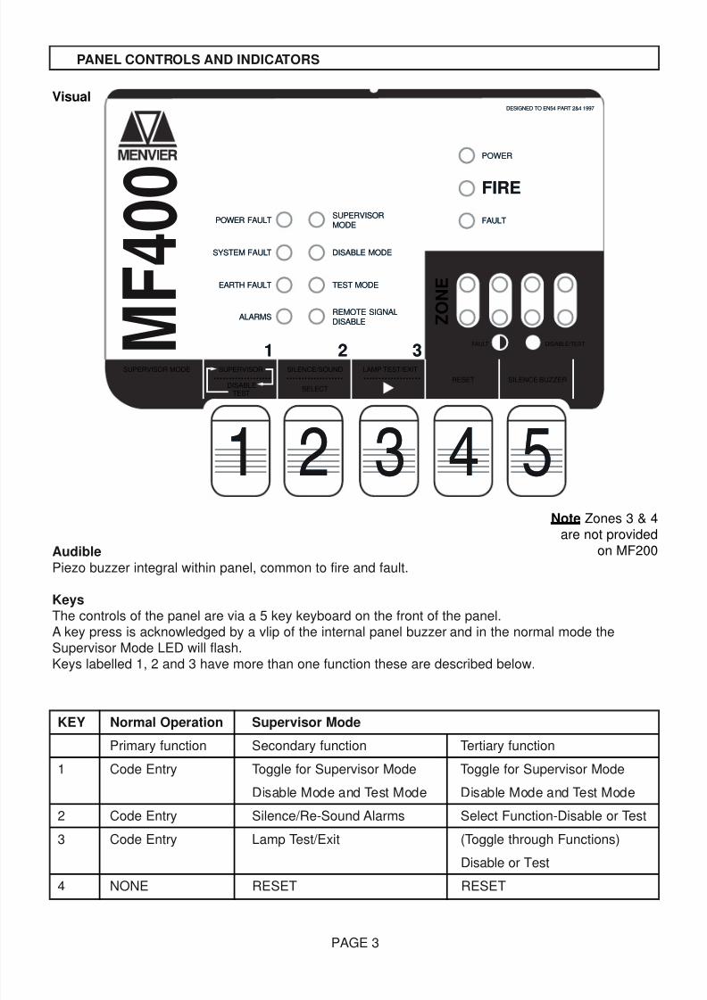
Audible
Piezo buzzer integral within panel, common to fire and fault.
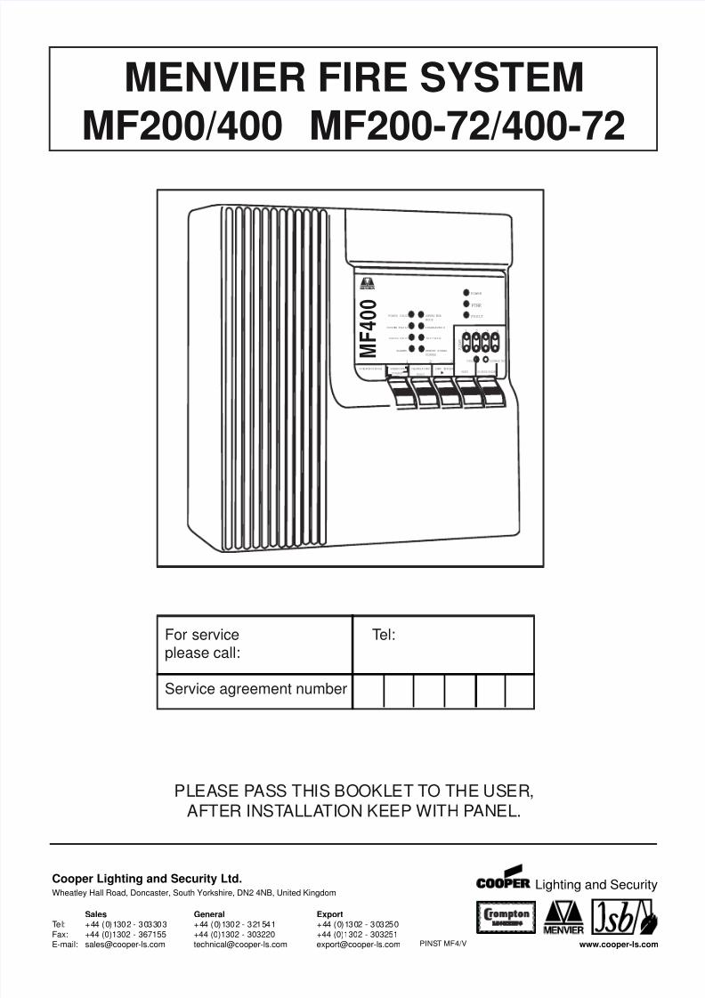
KeysThe controls of the panel are via a 5 key keyboard on the front of the panel.A key press is acknowledged by a vlip of the internal panel buzzer and in the normal mode theSupervisor Mode LED will flash.Keys labelled 1, 2 and 3 have more than one function these are described below.
KEY Normal Operation Supervisor Mode
Primary function Secondary function Tertiary function
1 Code Entry Toggle for Supervisor Mode Toggle for Supervisor Mode
Disable Mode and Test Mode Disable Mode and Test Mode
2 Code Entry Silence/Re-Sound Alarms Select Function-Disable or Test
3 Code Entry Lamp Test/Exit (Toggle through Functions)
Disable or Test
4 NONE RESET RESET
PAGE 3
PANEL CONTROLS AND INDICATORS
POWER FAULTPOWER FAULT
POWERPOWER
DESIGNED TO EN54 PART 2&4 1997DESIGNED TO EN54 PART 2&4 1997
FIREFIRE
11 22 33
Z O N E
FAULTFAULT
FAULT DISABLE/TEST
SYSTEM FAULTSYSTEM FAULT
EARTH FAULTEARTH FAULT
ALARMSALARMS
SUPERVISOR
DISABLETEST
SUPERVISOR MODE SILENCE/SOUND LAMP TEST/EXIT
RESET
SELECT
SILENCE BUZZER
SUPERVISORMODESUPERVISORMODE
DISABLE MODEDISABLE MODE
TEST MODETEST MODE
REMOTE SIGNALDISABLEREMOTE SIGNALDISABLE
...................................... ................... M
F 4 0 0
11 22 33 44 55Note Zones 3 & 4are not provided
on MF200
Visual

8/9/2019 Menvier MF400
http://slidepdf.com/reader/full/menvier-mf400 4/12
General
The panel has 2 levels of operation. Normal Mode and Supervisor Mode.
Normal Operation
Silence Buzzer (key 5)
The user can silence the PANEL buzzer by pressing the 'SILENCE BUZZER' key (at any time), thebuzzer will then give a beep approximately every 10 seconds.Note:- This does not silence the alarms only the panel buzzer.
Supervisor Mode Entry (key 1, key 2, key 3)
By entering a 4 digit access code the user will enter the Supervisor Mode. The access code is 2113.By pressing the keys in the correct order the user will see the Supervisor LED flash indicating the
panel is in Supervisor Mode.
Supervisor Mode Operation -Enter supervisor mode using access code 2113 prior to carryingout any of the following operations.Auto time-out of supervisor mode will occur 2 minutes after last action.
RESET (key 4)
Pressing 'RESET' at any time while in Supervisor Mode will reset the panel, clearing any fire, fault orTest Mode information. If a fire or fault exists the panel will re-enter the fire condition.Note:- Operating RESET will not clear disable information.
Lamp Test/Exit supervisor Mode (key 3)
While the supervisor LED is flashing the user can perform a lamp and buzzer test. All LED's will lightand the buzzer will sound. This also exits the Supervisor Mode.
Silence/Sound Alarms (key 2)
While the Supervisor LED is flashing pressing 'SOUND/SILENCE' will silence or sound the alarms. If
a fire is detected on another zone the alarms will re-sound.Note:- If the alarms are silenced and fire condition exists the panel buzzer will sound continuously.
Disable Mode (key 1, key 2, key 3)
The panel allows the supervisor to disable individual zones, both alarm lines together or the remotesignal output. When any of these functions are disabled the buzzer will beep.Zones, when disabled will not be monitored for fires or faults.Alarms, when disabled will not be monitored for faults, or be activated by a fire condition.Remote signal, when disabled will not be activated by a fire condition.
To disable/re-enable any of the above functions the following procedure should be followed:-
1. Press 'key 1' to toggle the flashing LED from 'Supervisor Mode' to 'Disable Mode'.
PAGE 4
PANEL OPERATION

8/9/2019 Menvier MF400
http://slidepdf.com/reader/full/menvier-mf400 5/12
2. Release and repress (key 3) to toggle through LED's representing each function.
3. When you highlight the LED representing each function to be enabled/disabled press'key select’ to enable/disable this function.
4. To exit Disable Mode and leave the panel in the disable state press 'key 1' to toggle to SupervisorMode LED and press ‘key 3’ or ‘key 4’
5. When a function is disabled the LED corresponding to that function will remain lit even when youexit the Disable Mode.
6. To reset from Disable Mode to Normal operation, press ‘keys 2-1-1-3’, repress ‘key 3’ to togglethrough LEDs to required Zone, press ‘key 2’Disable Mode LED flashing. This will extinguish in 2 minutes.
Test Mode (key 1, key 2, key 3)The panel allows the supervisor to test each zone individually or any combination of zones.When a zone is put into Test Mode the buzzer will beep.Remote signal will not operate when a fire signal is received from a zone in the test mode.The operation of zones which are not in the test mode will function as normal.A fire signal from a zone in test will cause the alarms to operate for a few seconds only.
To put a zone into Test Mode, the following procedure should be used:-.1. Press 'key 1' to toggle the flashing LED from 'Supervisor Mode' to 'Disable Mode' to 'Test Mode'.
2. Release and repress ‘key 3’ to toggle through LED's representing each zone.
3. When you highlight the LED corresponding to the zone to be put into Test / taken out of Testpress 'SELECT' (key 2) to select that zone. (Zone LED lit, Test LED flashing)
4. Each manual call point and detector on the zone in test can now be tested.
5. When a manual call point or detector is put into a fire condition on the zone in test, the alarmswill activate for approximately 2 seconds and the zone will remain in the fire condition forapproximately 10 seconds. The panel will then automatically reset the zones, which will takeapproximately 10 seconds. The panel will indicate a fire signal from a zone in test by turning onthe corresponding zone fire LED.
6. To clear all zone fire LED's press ‘key 3’.
7. To exit Test Mode and leave the panel in the test state press 'key 1' to toggle to Supervisor ModeLED and press 'Lamp Test/EXIT (key 3) or press 'RESET' (key4). Zone LED lit, Test LED lit.
8. To reset from Test Mode to Normal operation, press ‘keys 2-1-1-3’, ‘key 1-1’ (i.e. twice). Repress‘key 3’ to toggle through LEDs to required zone, press ‘key 2’Test Mode LED flashing. This will extinguish in 2 minutes.
Note:- Alarms cannot be put into test modeIf a manual call point or detector is left in a fire condition on a zone in test, the panel will carry out
step 5 until the fire signal is cleared.Operating 'RESET' will not clear test information. Test information is only lost when the mains supplyand battery are disconnected or the function is re-enabled.
PAGE 5
PANEL OPERATION - continued
8/9/2019 Menvier MF400
http://slidepdf.com/reader/full/menvier-mf400 6/12
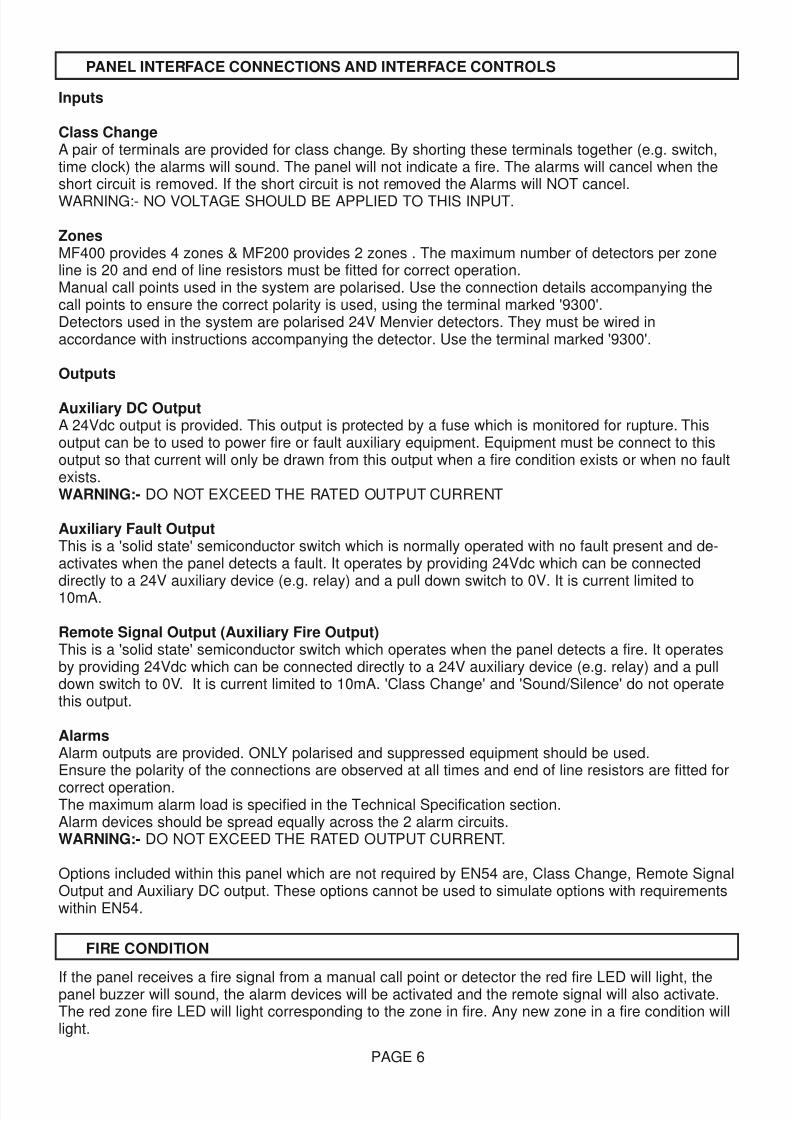
Inputs
Class ChangeA pair of terminals are provided for class change. By shorting these terminals together (e.g. switch,time clock) the alarms will sound. The panel will not indicate a fire. The alarms will cancel when theshort circuit is removed. If the short circuit is not removed the Alarms will NOT cancel.
WARNING:- NO VOLTAGE SHOULD BE APPLIED TO THIS INPUT.
ZonesMF400 provides 4 zones & MF200 provides 2 zones . The maximum number of detectors per zoneline is 20 and end of line resistors must be fitted for correct operation.Manual call points used in the system are polarised. Use the connection details accompanying thecall points to ensure the correct polarity is used, using the terminal marked '9300'.Detectors used in the system are polarised 24V Menvier detectors. They must be wired inaccordance with instructions accompanying the detector. Use the terminal marked '9300'.
Outputs
Auxiliary DC OutputA 24Vdc output is provided. This output is protected by a fuse which is monitored for rupture. Thisoutput can be to used to power fire or fault auxiliary equipment. Equipment must be connect to thisoutput so that current will only be drawn from this output when a fire condition exists or when no faultexists.WARNING:- DO NOT EXCEED THE RATED OUTPUT CURRENT
Auxiliary Fault OutputThis is a 'solid state' semiconductor switch which is normally operated with no fault present and de-activates when the panel detects a fault. It operates by providing 24Vdc which can be connecteddirectly to a 24V auxiliary device (e.g. relay) and a pull down switch to 0V. It is current limited to10mA.
Remote Signal Output (Auxiliary Fire Output)This is a 'solid state' semiconductor switch which operates when the panel detects a fire. It operatesby providing 24Vdc which can be connected directly to a 24V auxiliary device (e.g. relay) and a pulldown switch to 0V. It is current limited to 10mA. 'Class Change' and 'Sound/Silence' do not operatethis output.
AlarmsAlarm outputs are provided. ONLY polarised and suppressed equipment should be used.Ensure the polarity of the connections are observed at all times and end of line resistors are fitted for
correct operation.The maximum alarm load is specified in the Technical Specification section.Alarm devices should be spread equally across the 2 alarm circuits.WARNING:- DO NOT EXCEED THE RATED OUTPUT CURRENT.
Options included within this panel which are not required by EN54 are, Class Change, Remote SignalOutput and Auxiliary DC output. These options cannot be used to simulate options with requirementswithin EN54.
If the panel receives a fire signal from a manual call point or detector the red fire LED will light, thepanel buzzer will sound, the alarm devices will be activated and the remote signal will also activate.The red zone fire LED will light corresponding to the zone in fire. Any new zone in a fire condition willlight.
PAGE 6
PANEL INTERFACE CONNECTIONS AND INTERFACE CONTROLS
FIRE CONDITION
8/9/2019 Menvier MF400
http://slidepdf.com/reader/full/menvier-mf400 7/12
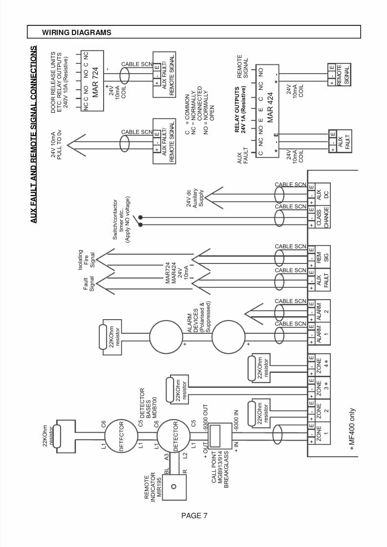
PAGE 7
WIRING DIAGRAMS
2 2 K O h m
r e s i s t o r
+ O U T
O U T
+ I N
I N
- 9 3 0 0
- 9 3 0 0
L 1
C 6
L 1
C 5
L 1
C 6
L 1
C 5
B L
A 3
R
L 2
+ +
2 2 K O h m
r e s i s t o r
2 2 K O h m
r e s i s t o r
2 2 K O h m
r e s i s t o r
2 2 K O h m
r e s i s t o r
2 4 V d c
A u x i l a r y
S u p p l y
CABLE SCN
CABLE SCN
CABLE SCN
CABLE SCN
CABLE SCN
CABLE SCN
CABLE SCN
CABLE SCN
F a u l t
S i g n a l
I s o l a t i n g
F i r e
S i g n a l
S w i t c h / c o n t a c t o r
t i m e r e t c . .
( A p p l y N O v o l t a g e )
R E M O T E
I N D I C A T O
R
M I R 1 9 5
A L A R M
D E V I C E S
( P o l a r i s e d &
S u p p r e s s e d )
M A R 7 2 4
M A R 4 2 4
2 4 V
1 0 m A
2 4 V 1 0 m A
P U L L T O 0 v
D O O R
R E L E A S E U N I T S
E T C . R
E L A Y O U T P U T S
2 4 0 V
1 0 A ( R e s i s t i v e )
R E L A Y
O U T P U
T S
2 4 V
1 A
( R e s i s t i v e )
N C
C
N O
N O
C
N C
C
N C
N O
E
E
C
N C
N O
2 4 V
1 0
m A
C
O I L
M
A R
7 2 4
M A R
4 2 4
2 4 V
1 0 m A
C
O I L
2 4 V
1 0 m A
C O I L
A U X
F A U L T
R E M O T E
S I G N A L
+
-
E
+
-
+
-
D E T E C T O R
D E T E C T O R
C A L L P O I N T
M G B 9 1 3 / 9 1 4
B R E
A K G L A S S
D E T E C T O R
B A S E S
M D B 7 0 0
+
-
E
Z O N E
1
+
-
E
Z O N E
2
+
-
E
Z O N E 3
+
-
E
Z O N E
4
+
-
E
A L A R M
1
+
-
E
A U X
F
A U L T
+
-
E
C L A S S
C H A N G E
+
-
E
A L A R M
2
+
-
E
R E M S I G
+
-
E
A U X D C
+
-
E
A U X
F A U L T
+
-
E
A U X F A U L T /
R E M O T E S I G N A L
+
-
E
A U X F A U L T /
R E M O T E S I G N A L
+
-
E
R E M O T E
S I G N A L
C
= C O M M O N
N C
= N O R M A L L
Y
C O N N E C T
E D
N O =
N O R M A L L
Y
O P E N
*
*
M F 4 0 0 o n l y
*
A U X F A U L T A N D
R E M O T E
S I G N A L C O N N E C T I O N S
8/9/2019 Menvier MF400
http://slidepdf.com/reader/full/menvier-mf400 8/12
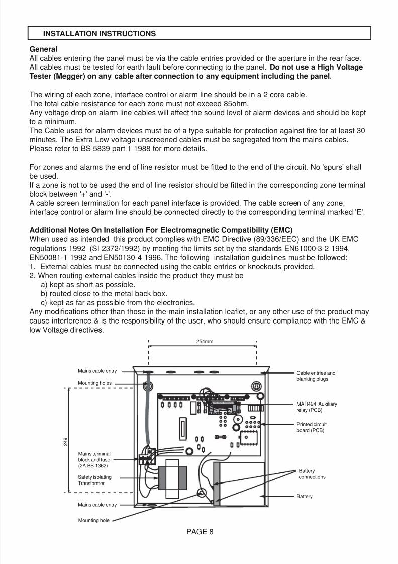
General
All cables entering the panel must be via the cable entries provided or the aperture in the rear face.All cables must be tested for earth fault before connecting to the panel. Do not use a High VoltageTester (Megger) on any cable after connection to any equipment including the panel.
The wiring of each zone, interface control or alarm line should be in a 2 core cable.The total cable resistance for each zone must not exceed 85ohm.Any voltage drop on alarm line cables will affect the sound level of alarm devices and should be keptto a minimum.The Cable used for alarm devices must be of a type suitable for protection against fire for at least 30minutes. The Extra Low voltage unscreened cables must be segregated from the mains cables.Please refer to BS 5839 part 1 1988 for more details.
For zones and alarms the end of line resistor must be fitted to the end of the circuit. No 'spurs' shallbe used.If a zone is not to be used the end of line resistor should be fitted in the corresponding zone terminal
block between '+' and '-'.A cable screen termination for each panel interface is provided. The cable screen of any zone,interface control or alarm line should be connected directly to the corresponding terminal marked 'E'.
Additional Notes On Installation For Electromagnetic Compatibility (EMC)When used as intended this product complies with EMC Directive (89/336/EEC) and the UK EMCregulations 1992 (SI 2372/1992) by meeting the limits set by the standards EN61000-3-2 1994,EN50081-1 1992 and EN50130-4 1996. The following installation guidelines must be followed:
1. External cables must be connected using the cable entries or knockouts provided.2. When routing external cables inside the product they must be
a) kept as short as possible.
b) routed close to the metal back box.c) kept as far as possible from the electronics.Any modifications other than those in the main installation leaflet, or any other use of the product maycause interference & is the responsibility of the user, who should ensure compliance with the EMC &low Voltage directives.
PAGE 8
INSTALLATION INSTRUCTIONS
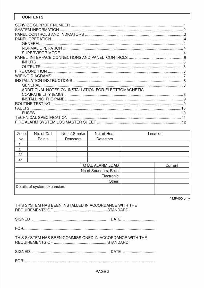
FAULTRELAY REM SIGRELAY
254mm
2 4 9
Battery
Mains cable entry
Battery
connections
Printed circuitboard (PCB)
MAR424 Auxiliaryrelay (PCB)
Cable entries andblanking plugs
Mains cable entry
Mounting holes
Mounting hole
Safety isolating
Transformer
Mains terminalblock and fuse(2A BS 1362)
8/9/2019 Menvier MF400
http://slidepdf.com/reader/full/menvier-mf400 9/12
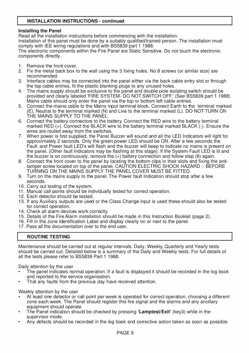
Installing the PanelRead all the installation instructions before commencing with the installation.Installation of this panel must be done by a suitably qualified/trained person. The installation mustcomply with IEE wiring regulations and with BS5839 part 1 1988.The electronic components within the Fire Panel are Static Sensitive. Do not touch the electroniccomponents directly.
1. Remove the front cover.2. Fix the metal back box to the wall using the 3 fixing holes. No 8 screws (or similar size) are
recommended.3. Interface cables may be connected into the panel either via the back cable entry slot or through
the top cable entries, fit the plastic blanking plugs to any unused holes.4. The mains supply should be exclusive to the panel and double pole isolating switch should be
provided and clearly labeled 'FIRE SYSTEM- DO NOT SWITCH OFF.' (See BS5839 part 1 1988)Mains cable should only enter the panel via the top or bottom left cable entries.
5. Connect the mains cable to the Mains input terminal block. Connect Earth to the terminal marked(E), Neutral to the terminal marked (N) and Live to the terminal marked (L). DO NOT TURN ONTHE MAINS SUPPLY TO THE PANEL.
6. Connect the battery connectors to the battery. Connect the RED wire to the battery terminalmarked RED (+). Connect the BLACK wire to the battery terminal marked BLACK (-). Ensure thewires are routed away from the switches.
7. When power is first supplied, the Panel Buzzer will sound and all the LED Indicators will light forapproximately 2 seconds. Only the green power LED should be ON. After a few seconds theFault and Power fault LED's will flash and the buzzer will beep to indicate no mains is present onthe panel. (Other fault Indicators may be flashing at this stage). If the System Fault LED is lit andthe buzzer is on continuously, remove the (+) battery connection and follow step (6) again.
8. Connect the front cover to the panel by locating the bottom clips in their slots and fixing the anti-tamper screw located on top of the panel. CAUTION ELECTRIC SHOCK HAZARD :- BEFORETURNING ON THE MAINS SUPPLY THE PANEL COVER MUST BE FITTED.
9. Turn on the mains supply to the panel. The Power fault Indication should stop after a fewseconds.
10. Carry out testing of the system.11. Manual call points should be individually tested for correct operation.12. Each detector should be tested.13. If any Auxiliary outputs are used or the Class Change input is used these should also be tested
for correct operation.14. Check all alarm devices work correctly.15. Details of the Fire Alarm installation should be made in this Instruction Booklet (page 2).16. Fill in the zone Identification Label and display clearly on or next to the panel.17. Pass all the documentation over to the end user.
Maintenance should be carried out at regular intervals. Daily, Weekly, Quarterly and Yearly testsshould be carried out. Detailed below is a summary of the Daily and Weekly tests. For full details ofall the tests please refer to BS5839 Part 1 1988.
Daily attention by the user• The panel indicates normal operation. If a fault is displayed it should be recorded in the log book
and reported to the service organisation.• That any faults from the previous day have received attention.
Weekly attention by the user• At least one detector or call point per week is operated for correct operation, choosing a different
zone each week. The Panel should register this fire signal and the alarms and any ancillaryequipment should operate
• The Panel indication should be checked by pressing 'Lamptest/Exit' (key3) while in thesupervisor mode.
• Any defects should be recorded in the log book and corrective action taken as soon as possible.
PAGE 9
INSTALLATION INSTRUCTIONS - continued
ROUTINE TESTING
8/9/2019 Menvier MF400
http://slidepdf.com/reader/full/menvier-mf400 10/12
General
All fault conditions on the fire panel will be indicated by the 'FAULT' LED flashing, the panel buzzerbeeping and at least one other fault specific LED flashing. The auxiliary fault output will de-activate.All faults indications will be cleared automatically if the fault is removed unless stated.CAUTION ELECTRIC SHOCK HAZARD :- BEFORE REMOVING THE PANEL COVER THE MAINSSUPPLY MUST BE TURNED OFF.
Specific Fault Indication Fault/ActionPower Fault LED Flashing The 240V Mains supply, battery standby supply, battery charger and
all the fuses are monitored for faults.Check the battery is connected to the charger correctly. Check theMains supply is switched on. Check the fuses for ruptures
Power LED Flashing The Fire Panel internal power supplies are monitored for faults.Check 240V Mains supply is turned on. Check the fuses for ruptures.If the problem persists contact your service company.
Zone(s) Fault LED Flashing The zone lines are monitored for open circuit, short circuit and
detector removed.Check the wiring for open circuits and short circuits. All detectors inthe system must be correctly fitted to the detector bases. Ensure theend of line resistors are correctly connected. If all the zone faultLED's are lit pressing 'RESET' whilst in the Supervisor Mode willclear this fault Indication.
Alarm Fault LED Flashing This fault should be investigated immediately as it should beassumed the alarms are not operational. Each alarm line is monitored
for open circuit and short circuit. The alarm line fuses are alsomonitored for ruptures. Exceeding rated Alarm and Aux DC load maycause internal power faults. If the Alarm lines switch off shortly after
operation check for alarm line over-load. Press 'RESET' whilst inSupervisor mode to clear the fault indication.Check the wiring for open circuits and short circuits Ensure the end ofline resistors are correctly connected. Check the fuses for ruptures.
Earth Fault LED Flashing The Fire Panel will indicate an earth fault if any connection to earthexists in any wiring connected to the panel, other than the Mainssupply Safety Earth. This could be caused if the any wiring insulationis broken, or ancillary equipment connected to the panel has a nonsafety earth connection. If the fault persists contact your service
company.System Fault LED on The Micro controller has a supervisor circuit monitoring it for correct
operation and has detected either a software or hardware fault. Toclear this fault indication press 'RESET' whilst in the SupervisorMode. If this fault persists contact your service company.
PAGE 10
FAULTS
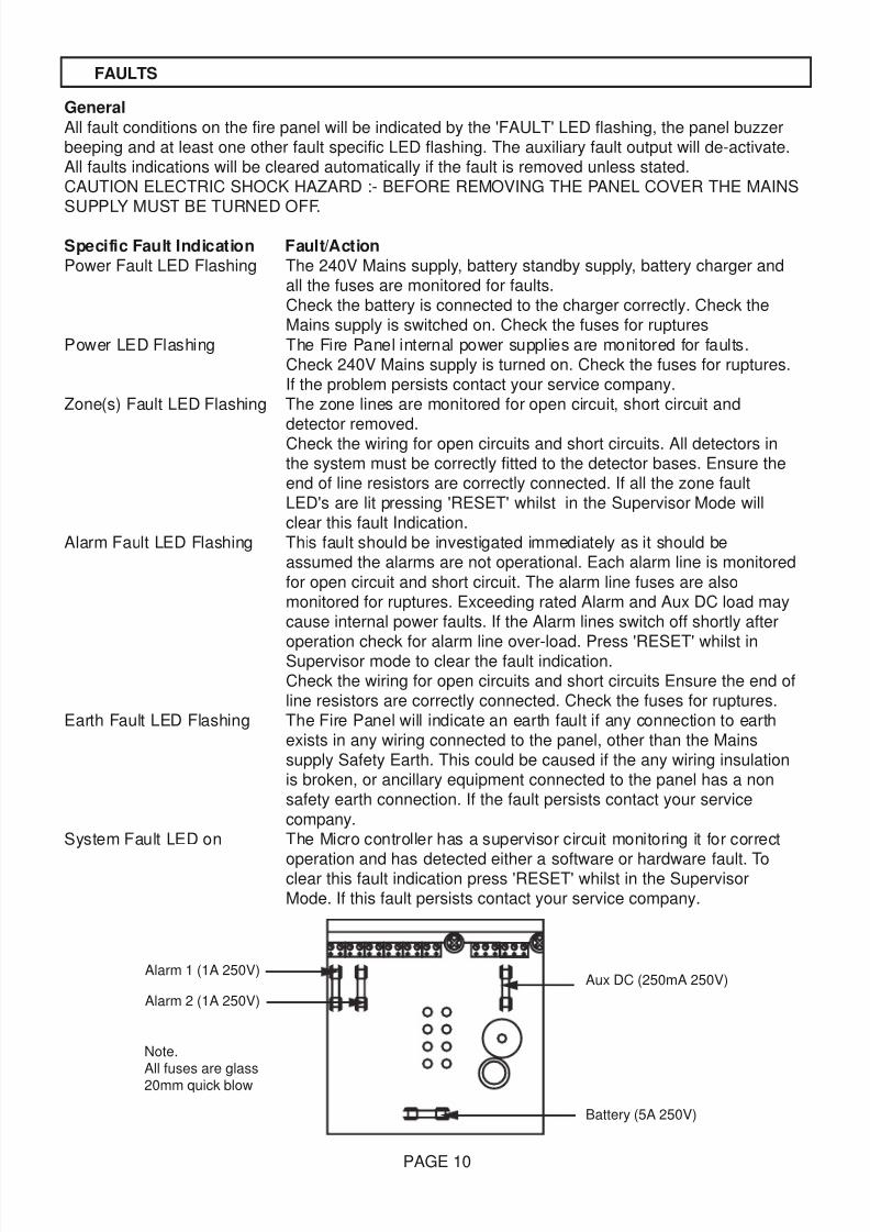
Aux DC (250mA 250V)Alarm 1 (1A 250V)
Alarm 2 (1A 250V)
Note.All fuses are glass20mm quick blow
Battery (5A 250V)
8/9/2019 Menvier MF400
http://slidepdf.com/reader/full/menvier-mf400 11/12
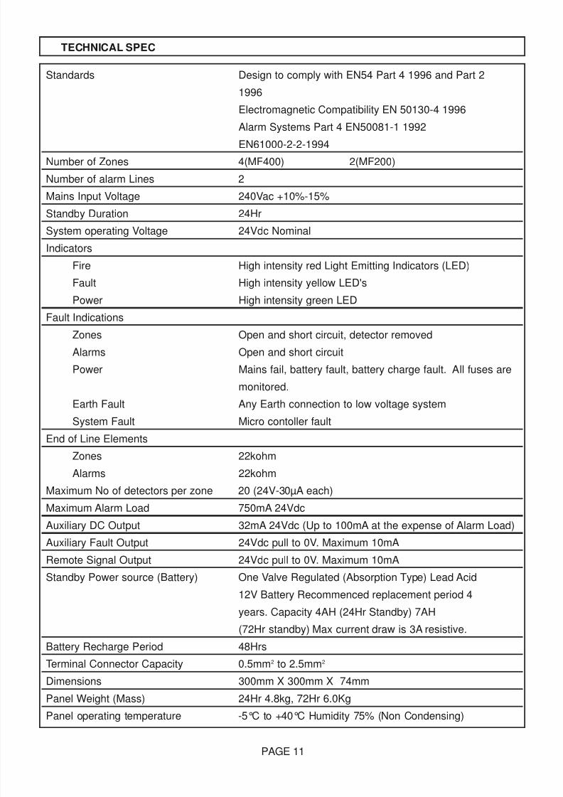
Standards Design to comply with EN54 Part 4 1996 and Part 2
1996
Electromagnetic Compatibility EN 50130-4 1996
Alarm Systems Part 4 EN50081-1 1992
EN61000-2-2-1994
Number of Zones 4(MF400) 2(MF200)
Number of alarm Lines 2
Mains Input Voltage 240Vac +10%-15%
Standby Duration 24Hr
System operating Voltage 24Vdc Nominal
Indicators
Fire High intensity red Light Emitting Indicators (LED)
Fault High intensity yellow LED's
Power High intensity green LED
Fault Indications
Zones Open and short circuit, detector removed
Alarms Open and short circuit
Power Mains fail, battery fault, battery charge fault. All fuses are
monitored.
Earth Fault Any Earth connection to low voltage system
System Fault Micro contoller fault
End of Line Elements
Zones 22kohm
Alarms 22kohm
Maximum No of detectors per zone 20 (24V-30µA each)
Maximum Alarm Load 750mA 24Vdc
Auxiliary DC Output 32mA 24Vdc (Up to 100mA at the expense of Alarm Load)
Auxiliary Fault Output 24Vdc pull to 0V. Maximum 10mA
Remote Signal Output 24Vdc pull to 0V. Maximum 10mA
Standby Power source (Battery) One Valve Regulated (Absorption Type) Lead Acid
12V Battery Recommenced replacement period 4
years. Capacity 4AH (24Hr Standby) 7AH
(72Hr standby) Max current draw is 3A resistive.
Battery Recharge Period 48Hrs
Terminal Connector Capacity 0.5mm2 to 2.5mm2
Dimensions 300mm X 300mm X 74mm
Panel Weight (Mass) 24Hr 4.8kg, 72Hr 6.0Kg
Panel operating temperature -5°C to +40°C Humidity 75% (Non Condensing)
PAGE 11
TECHNICAL SPEC
8/9/2019 Menvier MF400
http://slidepdf.com/reader/full/menvier-mf400 12/12
D a t e
T i m e
E v e n t
A c t i o n r e q u i r e d
D a t e
S i g n e d
C o m p l e
t e d
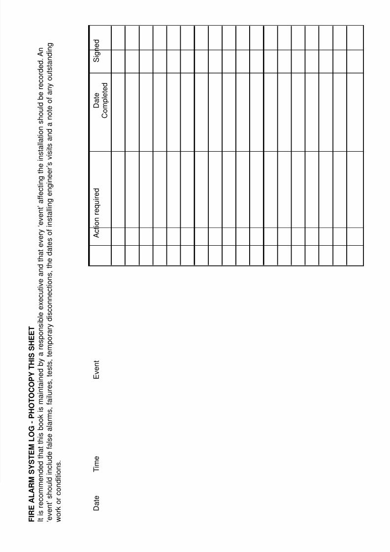
F I R E A L A R M S
Y S T E M L
O G -
P H O T O C O
P Y T H I S S H E E T
I t i s r e c o m m
e n d e d t h a t t h i s b o o k i s m a i n t a i n e d b y a r e s p o n s i b l e e x e c u t i v e a n d t h a t e v e r y ‘ e v e n t ’ a f f e
c t i n g t h e i n s t a l l a t i o n s h o u l d b e r e c o r d e d . A n
‘ e v e n t ’ s h o u l d i n c l u d e f a l s e a l a r m s , f a i l u r e
s , t e s t s , t e m p o r a r y d i s c o n n e c
t i o n s , t h e d a t e s o f i n s t a l l i n g e
n g i n e e r ’ s v i s i t s a n d a n o t e o f
a n y o u t s t a n d i n g
w o r k o r c o n d i t i o n s .