Embed Size (px)
DESCRIPTION
mechanical drawings
Citation preview
MEP201 Mechanical Engineering Drawing
1st semester 2005-2006
S R Kale
Lecture
Control Diagrams
Controls (2005) 2
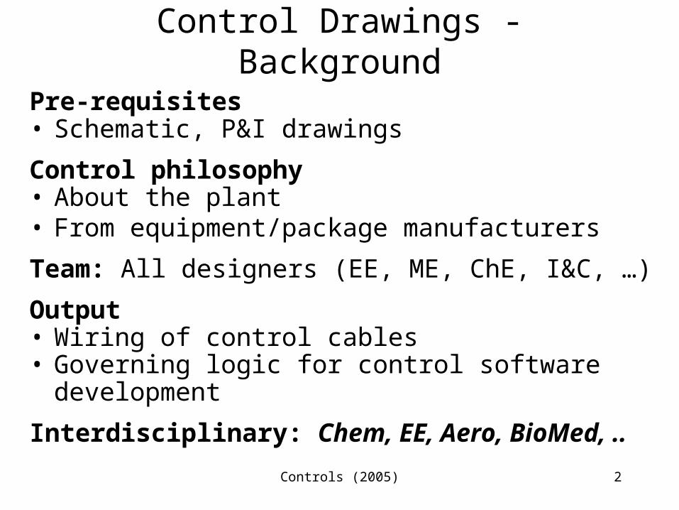
Control Drawings - Background
Pre-requisites• Schematic, P&I drawings
Control philosophy• About the plant• From equipment/package manufacturers
Team: All designers (EE, ME, ChE, I&C, …)
Output• Wiring of control cables• Governing logic for control software
development
Interdisciplinary: Chem, EE, Aero, BioMed, ..
Controls (2005) 3
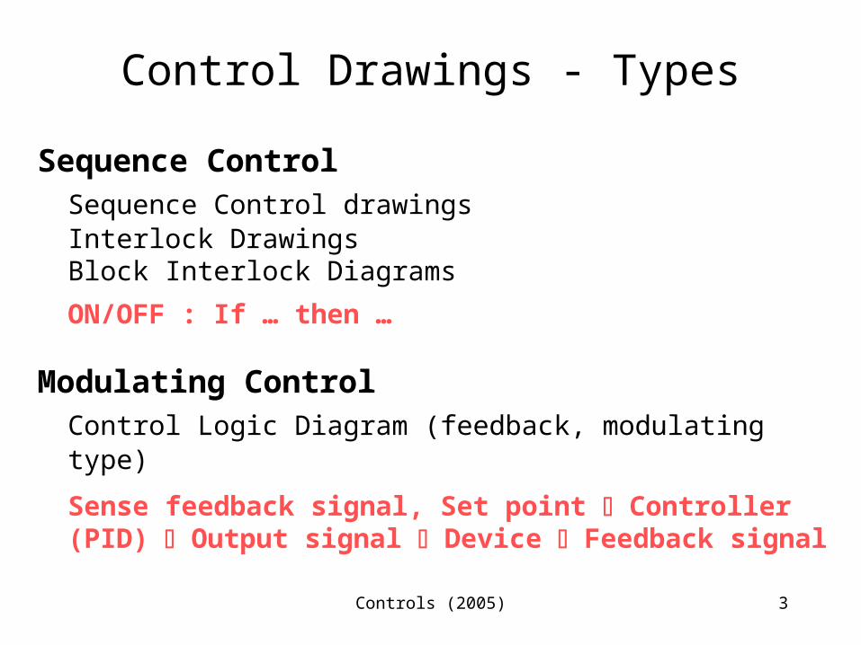
Control Drawings - Types
Sequence ControlSequence Control drawingsInterlock DrawingsBlock Interlock Diagrams
ON/OFF : If … then …
Modulating Control Control Logic Diagram (feedback, modulating type)
Sense feedback signal, Set point Controller (PID) Output signal Device Feedback signal
Controls (2005) 4
Sequence Control Drawings /
Block Interlock Diagram /Interlock Diagrams
Controls (2005) 5
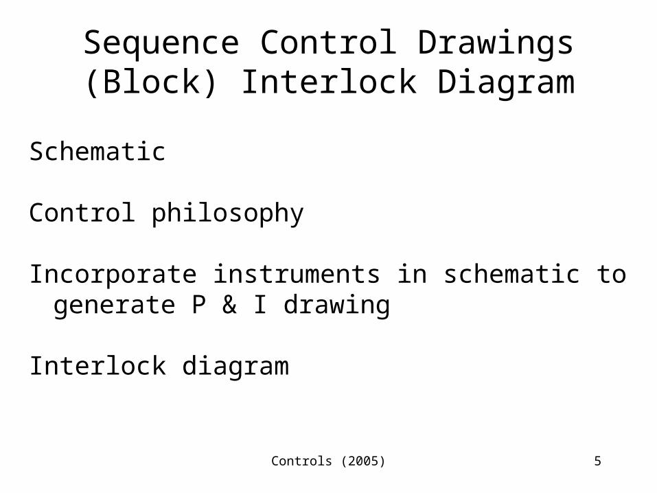
Sequence Control Drawings(Block) Interlock Diagram
Schematic
Control philosophy
Incorporate instruments in schematic to generate P & I drawing
Interlock diagram
Controls (2005) 6
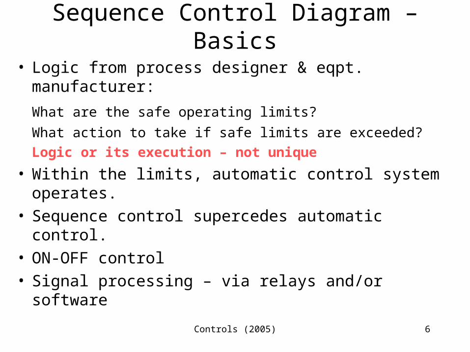
Sequence Control Diagram – Basics
• Logic from process designer & eqpt. manufacturer:
What are the safe operating limits?
What action to take if safe limits are exceeded?Logic or its execution – not unique
• Within the limits, automatic control system operates.
• Sequence control supercedes automatic control.
• ON-OFF control• Signal processing – via relays and/or software
Controls (2005) 7
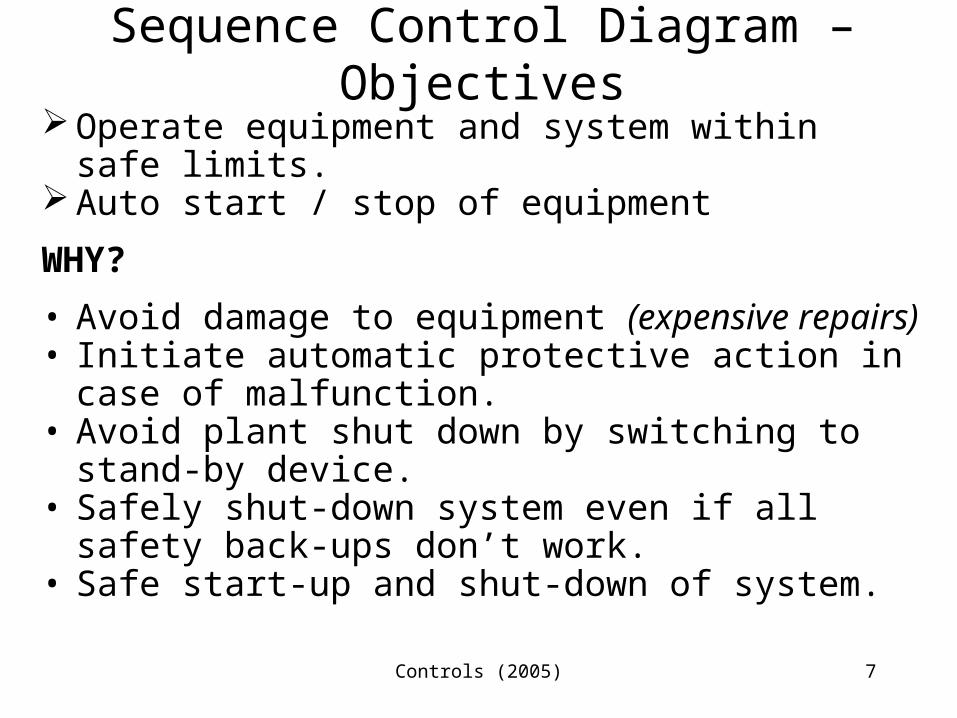
Sequence Control Diagram – Objectives
Operate equipment and system within safe limits.
Auto start / stop of equipment
WHY?
• Avoid damage to equipment (expensive repairs)
• Initiate automatic protective action in case of malfunction.
• Avoid plant shut down by switching to stand-by device.
• Safely shut-down system even if all safety back-ups don’t work.
• Safe start-up and shut-down of system.
Controls (2005) 8
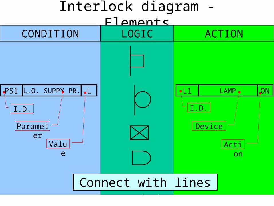
Interlock diagram - ElementsCONDITION LOGIC ACTION
PS1 L.O. SUPPY PR. L L1 LAMP ON
Parameter
Value
I.D. I.D.
Device
Action
Connect with lines
Controls (2005) 9
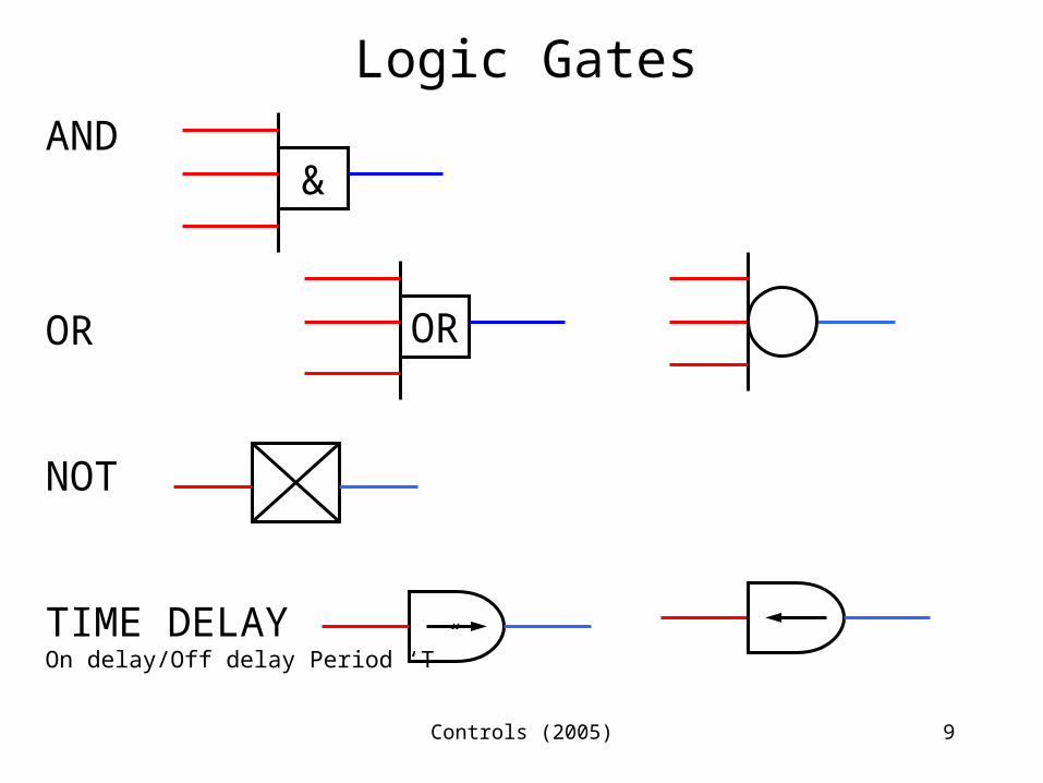
Logic GatesAND
OR
NOT
TIME DELAYOn delay/Off delay Period ‘T”
&
OR
Controls (2005) 10
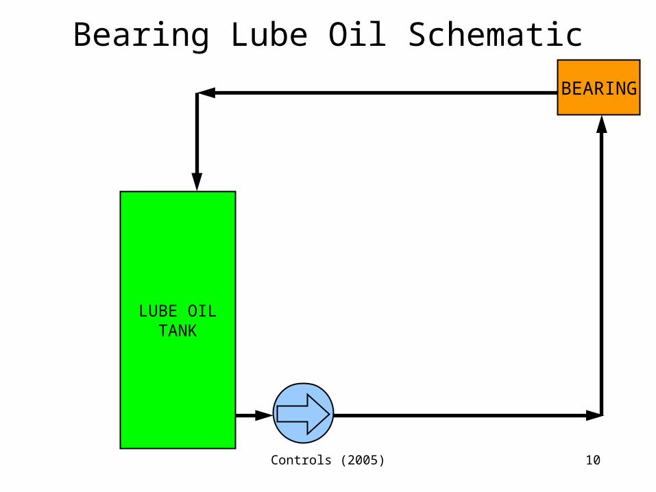
Bearing Lube Oil Schematic
LUBE OILTANK
BEARING
Controls (2005) 11
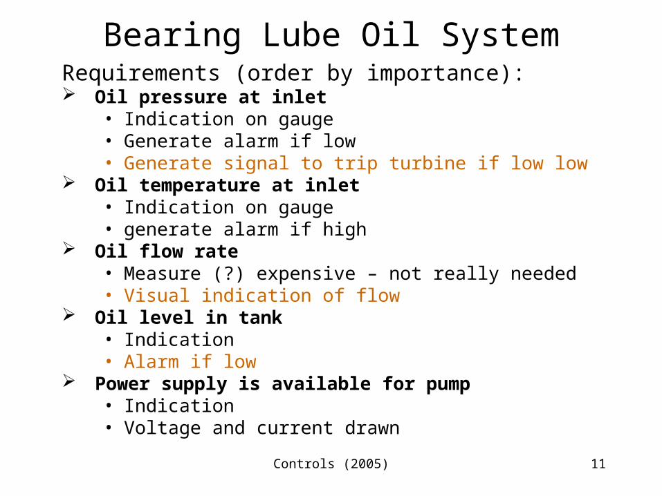
Bearing Lube Oil SystemRequirements (order by importance): Oil pressure at inlet
• Indication on gauge• Generate alarm if low• Generate signal to trip turbine if low low
Oil temperature at inlet• Indication on gauge• generate alarm if high
Oil flow rate• Measure (?) expensive – not really needed• Visual indication of flow
Oil level in tank• Indication• Alarm if low
Power supply is available for pump• Indication• Voltage and current drawn
Controls (2005) 12
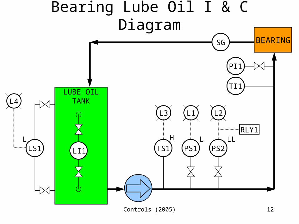
Bearing Lube Oil I & C Diagram
LUBE OILTANK
BEARING
LI1
SG
L1
PS1L
L3
TS1H
PI1
TI1
LS1
L4
L
L2
PS2LL
RLY1
Controls (2005) 13
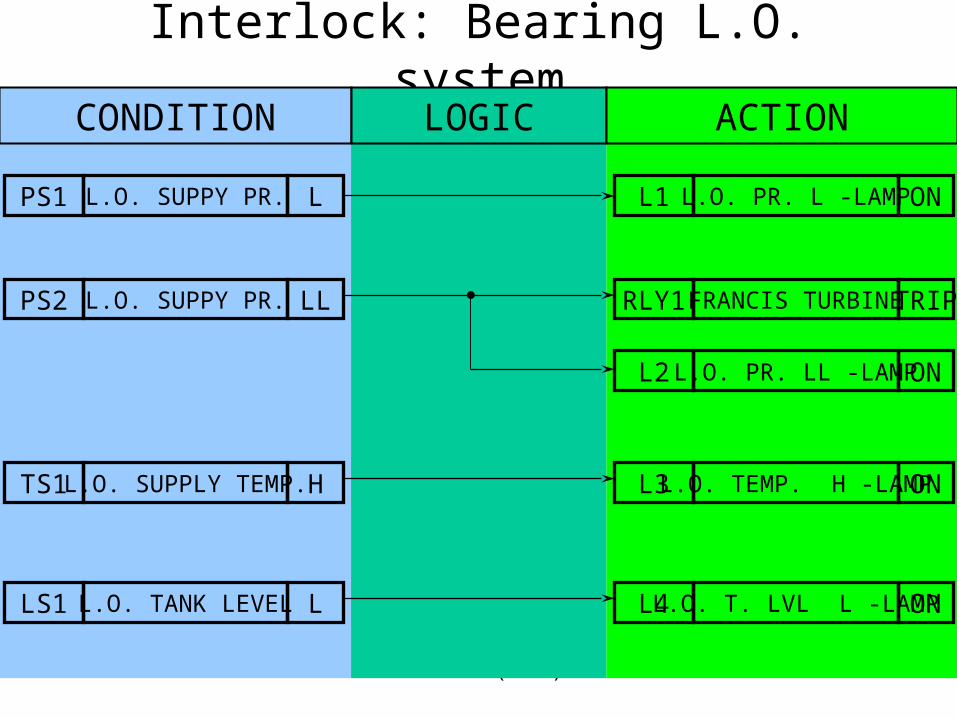
Interlock: Bearing L.O. systemCONDITION LOGIC ACTION
PS1 L.O. SUPPY PR. L L1 L.O. PR. L -LAMP ON
PS2 L.O. SUPPY PR. LL RLY1 FRANCIS TURBINE TRIP
L2 L.O. PR. LL -LAMP ON
TS1 L.O. SUPPLY TEMP. H L3 L.O. TEMP. H -LAMP ON
LS1 L.O. TANK LEVEL L L4 L.O. T. LVL L -LAMP ON
Controls (2005) 14
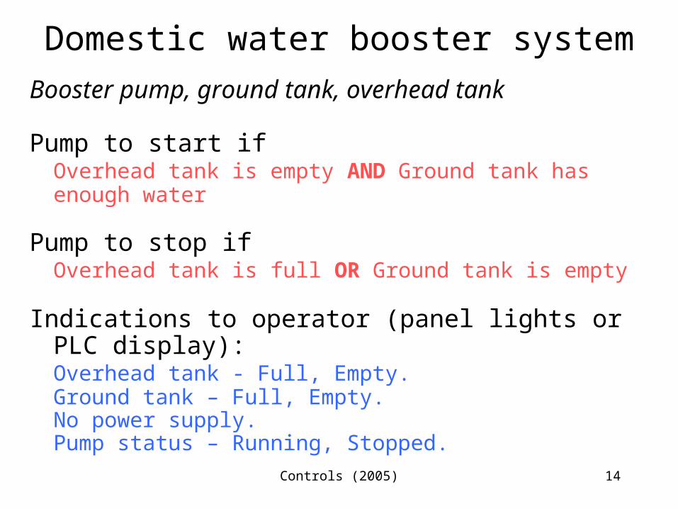
Domestic water booster systemBooster pump, ground tank, overhead tank
Pump to start ifOverhead tank is empty AND Ground tank has enough water
Pump to stop ifOverhead tank is full OR Ground tank is empty
Indications to operator (panel lights or PLC display):Overhead tank - Full, Empty.Ground tank – Full, Empty.No power supply.Pump status – Running, Stopped.
Controls (2005) 15
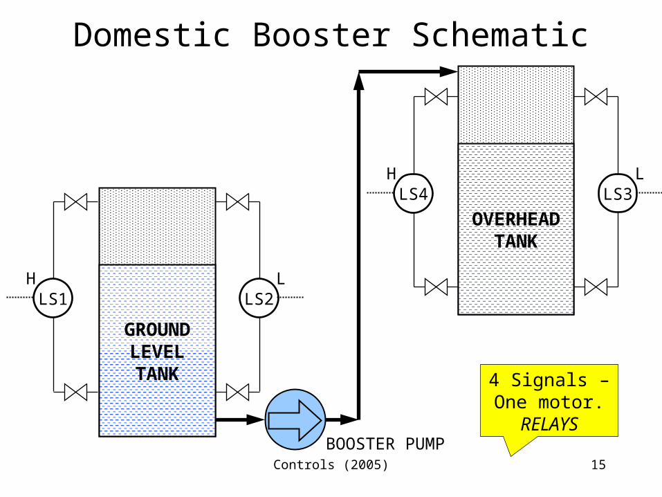
Domestic Booster Schematic
LS1H
LS2L
LS3L
LS4H
GROUNDLEVELTANKGROUND
LEVELTANK
GROUNDLEVELTANKOVERHEADTANK
BOOSTER PUMP
4 Signals –One motor.
RELAYS
Controls (2005) 16
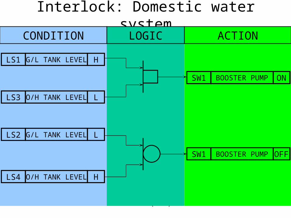
Interlock: Domestic water system
CONDITION LOGIC ACTION
LS1 G/L TANK LEVEL H
LS3 O/H TANK LEVEL L
SW1 BOOSTER PUMP ON
SW1 BOOSTER PUMP OFF
LS2 G/L TANK LEVEL L
LS4 O/H TANK LEVEL H
Controls (2005) 17
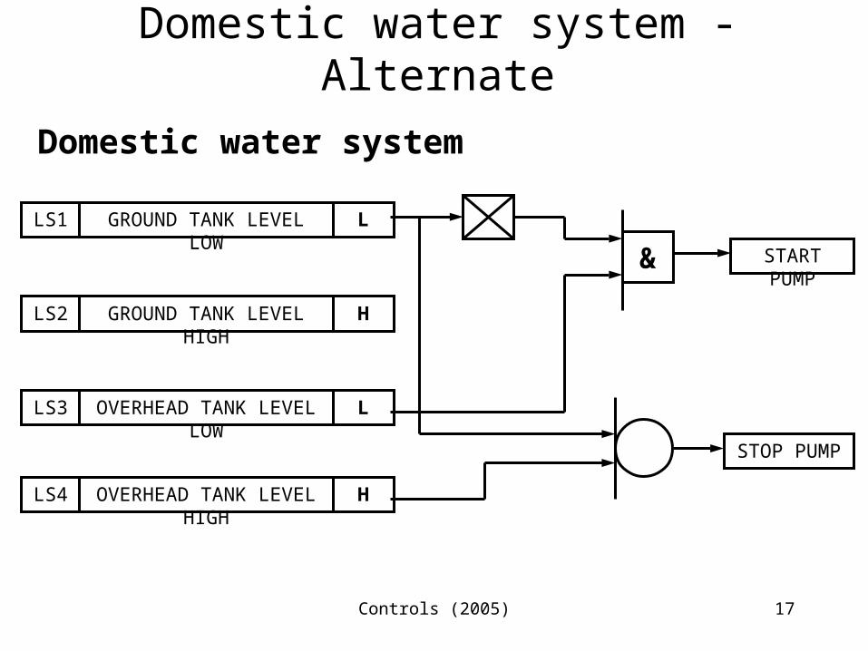
Domestic water system - Alternate
Domestic water system
LS4 OVERHEAD TANK LEVEL HIGH H
LS2 GROUND TANK LEVEL HIGH H
LS3 OVERHEAD TANK LEVEL LOW L
LS1 GROUND TANK LEVEL LOW L
START PUMP
STOP PUMP
&
Controls (2005) 18
Diesel engine of DG set/Loco
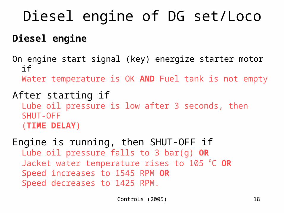
Diesel engine
On engine start signal (key) energize starter motor ifWater temperature is OK AND Fuel tank is not empty
After starting ifLube oil pressure is low after 3 seconds, then SHUT-OFF(TIME DELAY)
Engine is running, then SHUT-OFF ifLube oil pressure falls to 3 bar(g) ORJacket water temperature rises to 105 oC ORSpeed increases to 1545 RPM ORSpeed decreases to 1425 RPM.
Controls (2005) 19
Air conditioner (window/split)
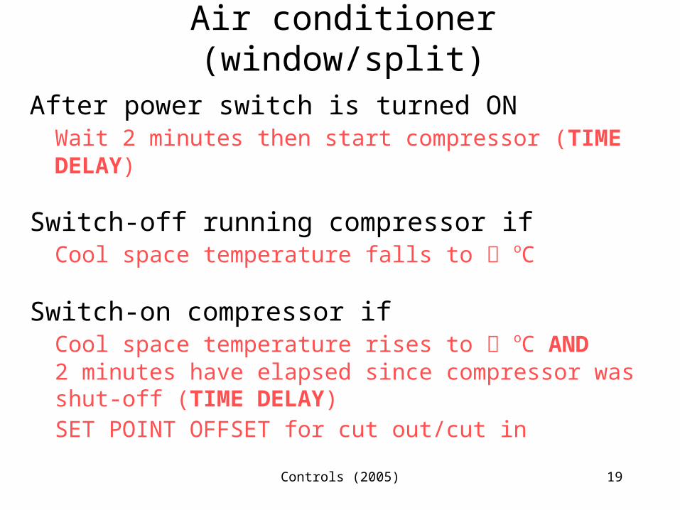
After power switch is turned ONWait 2 minutes then start compressor (TIME DELAY)
Switch-off running compressor ifCool space temperature falls to oC
Switch-on compressor ifCool space temperature rises to oC AND2 minutes have elapsed since compressor was shut-off (TIME DELAY)SET POINT OFFSET for cut out/cut in
Controls (2005) 20
Airplanes
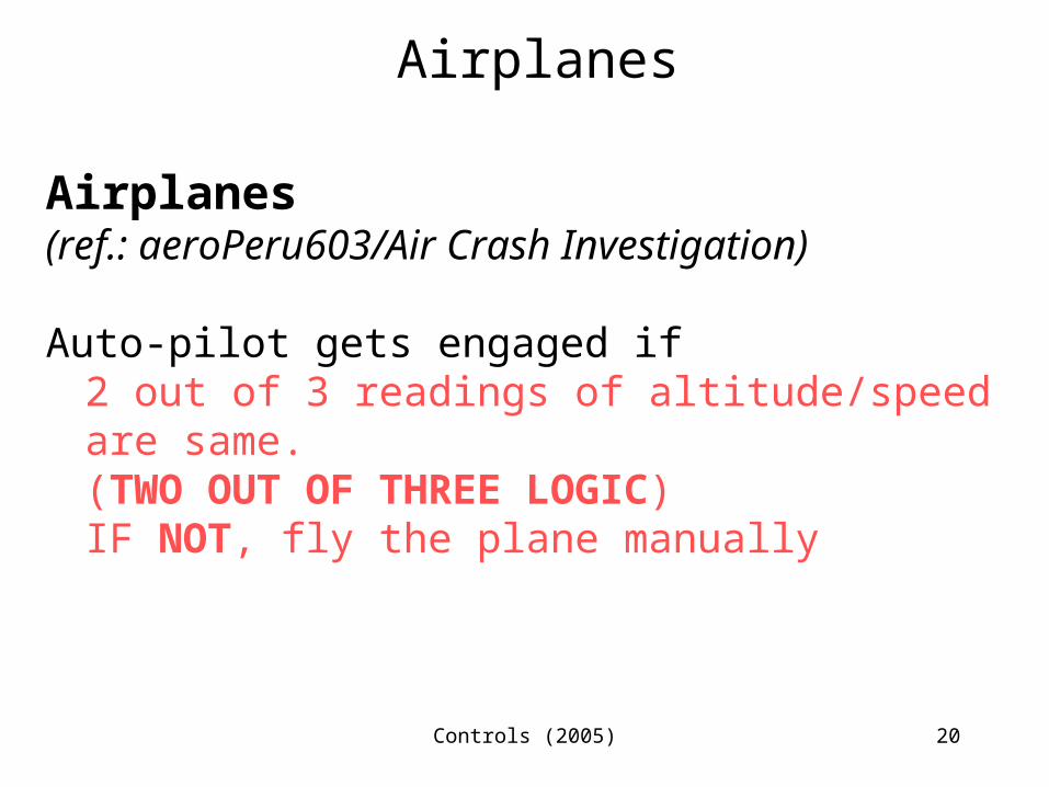
Airplanes(ref.: aeroPeru603/Air Crash Investigation)
Auto-pilot gets engaged if2 out of 3 readings of altitude/speed are same.(TWO OUT OF THREE LOGIC)IF NOT, fly the plane manually
Controls (2005) 21
Francis turbine
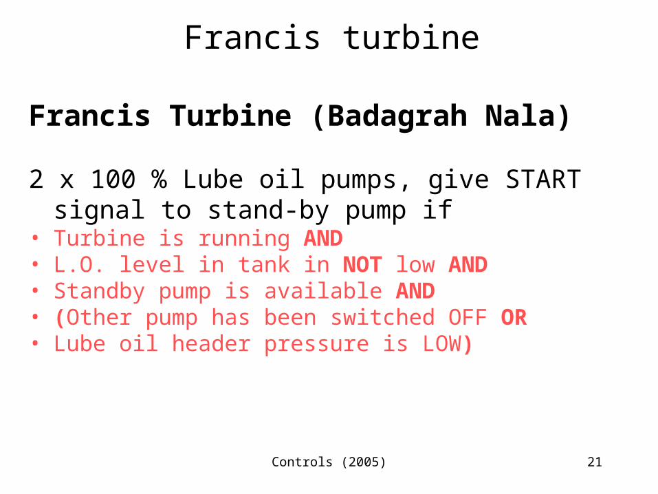
Francis Turbine (Badagrah Nala)
2 x 100 % Lube oil pumps, give START signal to stand-by pump if
• Turbine is running AND• L.O. level in tank in NOT low AND• Standby pump is available AND• (Other pump has been switched OFF OR• Lube oil header pressure is LOW)
Controls (2005) 22
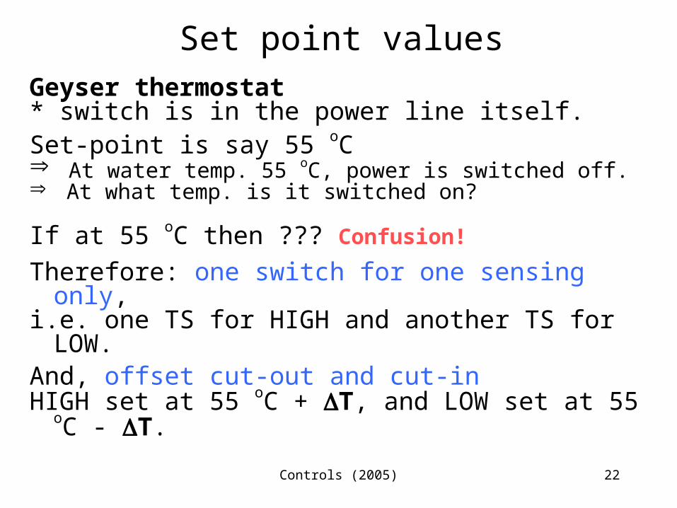
Set point valuesGeyser thermostat* switch is in the power line itself.Set-point is say 55 oC At water temp. 55 oC, power is switched off. At what temp. is it switched on?
If at 55 oC then ??? Confusion!
Therefore: one switch for one sensing only,i.e. one TS for HIGH and another TS for LOW.And, offset cut-out and cut-inHIGH set at 55 oC + T, and LOW set at 55 oC -
T.
Controls (2005) 23
Sequence Control Diagram – Examples
• BFP of CCPP : start and trip permissive• Standby BFP of CCPP : start permissive• Representation on P&I diagram• Typical interlock diagram - CCPP
Controls (2005) 24
Sequence Control – Haywire
• Equipment damage• Equipment/device does not start or shut-off
Controls (2005) 25
Sequence control - Summary
Outcome:
• Details of signal sources• Signal connections• Control logic for programming and hardware• Merge with layouts to generate control cable
routing, its length and size (BoM)• Modify piping drawings to accommodate
instruments/switches
Controls (2005) 26
Modulating Control
Controls (2005) 27
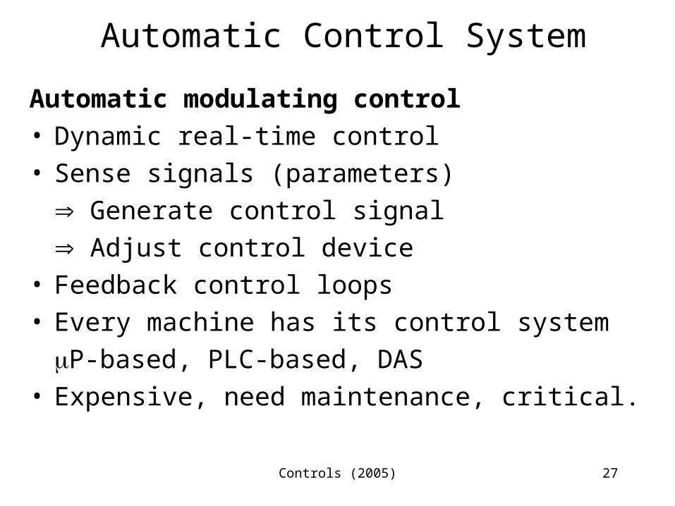
Automatic Control System
Automatic modulating control• Dynamic real-time control• Sense signals (parameters)
Generate control signal Adjust control device
• Feedback control loops• Every machine has its control system
P-based, PLC-based, DAS• Expensive, need maintenance, critical.
Controls (2005) 28
Automatic controls- Example
• Control loop #1 (CCPP steam system) :Flow control• Control loop #2 (CCPP steam system) : Pressure & t
emperature control
Controls (2005) 29
Automatic controls - Elements
Name and symbolController output not taken as input for
sensing resulting action, e.g. signal produced for adjusting valve stem. As a result of this action what is the position of the valve stem?
Sense valve stem position with a position sensor.
Controls (2005) 30
Automatic controls
More in course MEL312 Control Theory & Applications