Embed Size (px)
Citation preview
ENVIRONMENTAL TEST PROGRAM FOR THEMARS EXPLORATION ROVER PROJECT
Terry C. Fisher (1), Paul L. Van Velzer (2)
Jet Propulsion Laboratory, California Institute of Technology4800 Oak Grove Drive, Pasadena, CA 91109 USA
(1) Email: [email protected], (2) Email: [email protected]
ABSTRACT
On June 10 and July 7, 2003 the National Aeronautics and Space Administration (NASA)launched two spacecraft from Cape Canaveral, Florida for a six (6) months flight to the Red Planet,Mars. The two Mars Exploration Rover spacecraft landed safely on the planet in January 2004.
Prior to the successful launch, both of the spacecraft were involved in a comprehensive testcampaign that included development, qualification, and protoflight test programs. Testing wasperformed to simulate the environments associated with launch, inter-planetary cruise, landing onthe planet and Mars surface operations.
Unique test requirements included operating the spacecraft while the chamber pressure wascontrolled to simulate the decent to the planet from deep space, high impact landing loads and roveroperations on the surface of the planet at 8 Torr and –130ºC.
This paper will present an overview of the test program that included vibration, pyro-shock,landing loads, acoustic noise, thermal vacuum and solar simulation testing at the Jet PropulsionLaboratory (JPL) Environmental Test Laboratory facilities in Pasadena, California.
INTRODUCTION
The National Aeronautics and Space Administration’s (NASA's) twin robot geologists, theMars Exploration Rovers, were launched toward Mars in 2003 in search of answers about thehistory of water on Mars. The first rover, named “Spirit”, landed safely on the surface of Mars onJanuary 3, 2004. The second rover, named “Opportunity”, landed safely on January 24, 2004.
The Mars Exploration Rover (MER) mission is part of NASA's Mars Exploration Program,a long-term effort of robotic exploration of the red planet. The program seeks to take advantage ofeach launch opportunity to go to Mars. Primary among the mission's scientific goals is to search forand characterize a wide range of rocks and soils that hold clues to past water activity on Mars. Thespacecraft were targeted to sites that appear to have been affected by liquid water in the past.
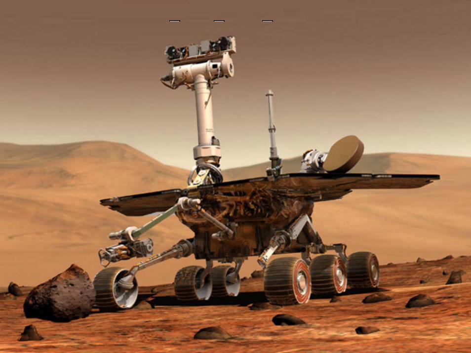
The mission scenario is that after the airbag protected landing, the spacecraft will settle ontothe surface and open, the rovers will roll out to take panoramic images. These images will givescientists the information they need to select promising geological targets that will tell part of thestory of water in Mars' past. Then, the rovers will drive (Fig. 1.) to those locations to perform on-site scientific investigations over the course of their nominal 90-day mission.
https://ntrs.nasa.gov/search.jsp?R=20050203721 2018-10-13T12:33:58+00:00Z
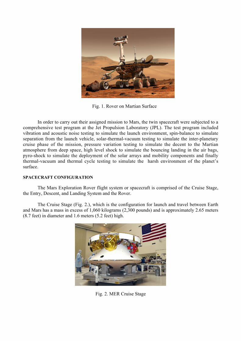
Fig. 1. Rover on Martian Surface
In order to carry out their assigned mission to Mars, the twin spacecraft were subjected to acomprehensive test program at the Jet Propulsion Laboratory (JPL). The test program includedvibration and acoustic noise testing to simulate the launch environment, spin-balance to simulateseparation from the launch vehicle, solar-thermal-vacuum testing to simulate the inter-planetarycruise phase of the mission, pressure variation testing to simulate the decent to the Martianatmosphere from deep space, high level shock to simulate the bouncing landing in the air bags,pyro-shock to simulate the deployment of the solar arrays and mobility components and finallythermal-vacuum and thermal cycle testing to simulate the harsh environment of the planet’ssurface.
SPACECRAFT CONFIGURATION
The Mars Exploration Rover flight system or spacecraft is comprised of the Cruise Stage,the Entry, Descent, and Landing System and the Rover.
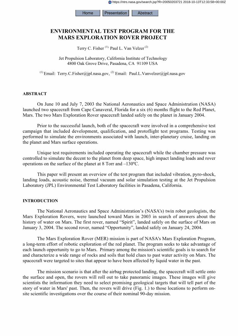
The Cruise Stage (Fig. 2.), which is the configuration for launch and travel between Earthand Mars has a mass in excess of 1,060 kilograms (2,300 pounds) and is approximately 2.65 meters(8.7 feet) in diameter and 1.6 meters (5.2 feet) high.
Fig. 2. MER Cruise Stage
The Entry, Descent, and Landing System configuration is used for the entry into the MartianAtmosphere and landing on the surface of Mars. The system includes the heatshield and backshell,retro rockets, the parachute, the airbags and lander structure.
The Rover is the heart of the flight system. All navigation, propulsion, mobility, power, andcommunication are controlled via the electronic systems contained in the Rover. The Rover is awheeled vehicle that carries the science instruments to different points of interest on the planet. Theinstruments on the Rover include imagers, spectrometers, and the Rock Abrasion Tool. The imagersare the Panoramic Cameras, Hazard Avoidance Cameras, Navigation Cameras, and the MicroscopicImager. The spectrometers are the Miniature Thermal Emissions Spectrometer, MossbauerSpectrometer, and Alpha Particle X-Ray Spectrometer. These science and engineering instrumentsare state-of-the-art tools that will acquire important science information that will help characterize awide range of rocks and soils that hold clues to past water activity on Mars.
OVERVIEW OF THE MER ENVIRONMENTAL TEST PROGRAM
The majority of the environmental testing for the MER project was performed in the JPLEnvironmental Test Laboratory (ETL) in Pasadena, California. Testing in the ETL includeddevelopment and flight qualification environmental tests at the component, assembly, sub-system,and system levels. Environmental tests included thermal, thermal cycle, thermal-vacuum, solar-thermal-vacuum, vibration, shock, landing loads and acoustic noise.
The hardware had to be subjected to a test program that would simulate the temperatureextremes of the Martian surface and since the MER landler was to be much more massive than thesuccessful Mars Pathfinder Rover (Fig. 3.) which landed on Mars in 1997, a developmental testprogram was started in the early stages of the MER project to design and qualify components tosurvive the landing environment on Mars. Numerous vibration, sine-pulse and sine-burst tests wereperformed on development hardware prior to the fabrication of the flight systems. Flight systemtesting included vibration, acoustic and thermal-vacuum tests of both rovers and the 2 flightspacecraft.
Fig. 3. Size comparison of the 1997 and the 2003 Mars Rovers
Additional environmental testing was carried out at other facilities like NASA’s GlennPlumbrook Station where the air bags were subjected to drop tests in the very large Space PowerFacility vacuum chamber and landing loads testing at National Technical Systems (NTS) centrifugefacility in Southern California. Many of the electronic sub-systems such as the UHF radio and theradar altimeter had thermal-vacuum and vibration testing performed at the manufacturer’s facilitiesprior to integration into the flight system at JPL.
Because of the large amount of developmental, qualification and protoflight testing and re-testing required during a very short time frame, the efficient and maximum utilization of testfacilities was very important. To help accomplish this very aggressive test program, the ETLmaintained close contact with project’s management through the use of weekly test scheduling andstatus meetings. The use of off-site vibration test facilities at Northrop Grumman Space Systems(formerly TRW), and Northrop Grumman Electronic Systems (formerly Aerojet) helped relieve theworkload on the JPL Environmental Test Lab.
JPL ENVIRONMENTAL TEST FACILITIES
The Environmental Test Lab at JPL is comprised of numerous horizontal thermal-vacuumchambers of various sizes ranging from 0.9 meter (3 feet) to 3 meters (10 feet) in diameter by 1meter (3.3 feet) to 4.3 meters (14 feet) in length. These chambers are capable of high vacuum levelsof 10-6 Torr with a temperature range of +125ºC to –185ºC. These chambers were used forcomponent, assembly, and sub-system level thermal vacuum testing of the various MER hardware.The ETL also has two large vertical thermal-vacuum chambers. The smaller chamber is referred toas the 10-ft Space Simulator Facility and is 3.0 meters (10 feet) in diameter and 13.7 meters (45feet) tall. This facility was used extensively for the Martian surface testing of the two rovers. Thischamber is capable of high vacuum operations, but for this test program the majority of the testingwas conducted at the Mars surface pressure of approximately 8 Torr (10 millibar).
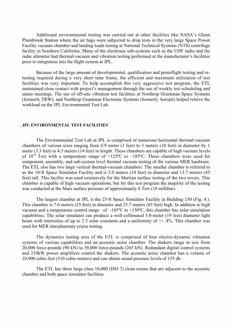
The largest chamber at JPL is the 25-ft Space Simulator Facility in Building 150 (Fig. 4.).This chamber is 7.6 meters (25 feet) in diameter and 25.7 meters (85 feet) high. In addition to highvacuum and a temperature control range of -185ºC to +150ºC, this chamber has solar simulationcapabilities. The solar simulator can produce a well-collimated 5.8-meter (19 feet) diameter lightbeam with intensities of up to 2.3 solar constants and a uniformity of +/- 4%. This chamber wasused for MER interplanetary cruise testing.
The dynamics testing area of the ETL is comprised of four electro-dynamic vibrationsystems of various capabilities and an acoustic noise chamber. The shakers range in size from20,000 force-pounds (90 kN) to 58,000 force-pounds (265 kN). Redundant digital control systemsand 210kW power amplifiers control the shakers. The acoustic noise chamber has a volume of10,900 cubic-feet (310 cubic-meters) and can obtain sound pressure levels of 155 db.
The ETL has three large class 10,000 (ISO 7) clean rooms that are adjacent to the acousticchamber and both space simulator facilities.
Data acquisition and recording in the ETL is provided by state-of-the-art digital datasystems. In the thermal-vacuum test areas data is collected via a 1000 channel high speed systemthat records thermocouple output, voltage, current and pressure data from various transducers on theunit under test and from the facility. Dynamic test data of up to 200 channels is recorded andanalyzed either by the control system or on various digital recorders.
Fig. 4. 25-ft Space Simulator
MER DYNAMICS TEST PROGRAM
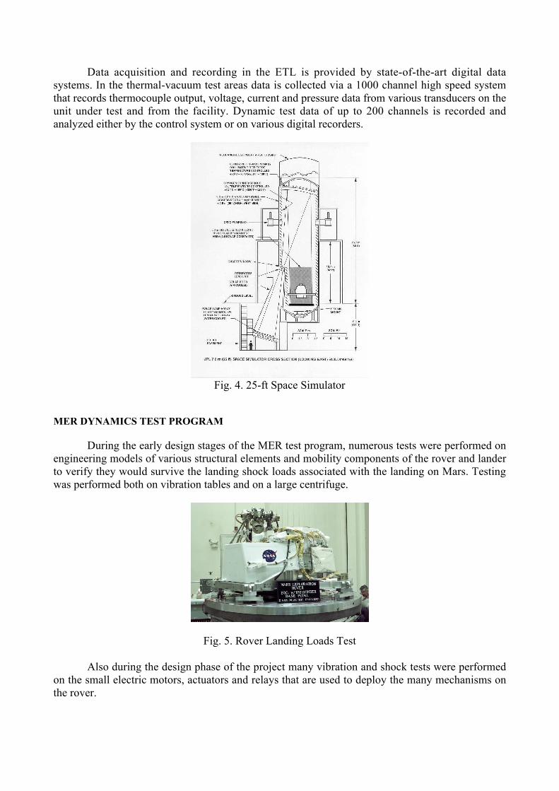
During the early design stages of the MER test program, numerous tests were performed onengineering models of various structural elements and mobility components of the rover and landerto verify they would survive the landing shock loads associated with the landing on Mars. Testingwas performed both on vibration tables and on a large centrifuge.
Fig. 5. Rover Landing Loads Test
Also during the design phase of the project many vibration and shock tests were performedon the small electric motors, actuators and relays that are used to deploy the many mechanisms onthe rover.
During the flight acceptance test phase of the project, numerous assemblies and subsystemswere tested in random vibration environments. Units such as antennas, mobility components,mechanisms, electronic chassis, cameras, and spectrometers were tested in the ETL and at off-sitetest facilities. Random vibration testing was performed in all three axes at levels of 5.5 to 8.0 Grms,depending on the requirements of each individual unit under test.
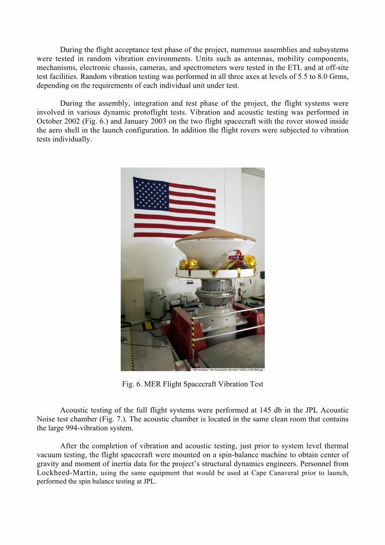
During the assembly, integration and test phase of the project, the flight systems wereinvolved in various dynamic protoflight tests. Vibration and acoustic testing was performed inOctober 2002 (Fig. 6.) and January 2003 on the two flight spacecraft with the rover stowed insidethe aero shell in the launch configuration. In addition the flight rovers were subjected to vibrationtests individually.
Fig. 6. MER Flight Spacecraft Vibration Test
Acoustic testing of the full flight systems were performed at 145 db in the JPL AcousticNoise test chamber (Fig. 7.). The acoustic chamber is located in the same clean room that containsthe large 994-vibration system.
After the completion of vibration and acoustic testing, just prior to system level thermalvacuum testing, the flight spacecraft were mounted on a spin-balance machine to obtain center ofgravity and moment of inertia data for the project’s structural dynamics engineers. Personnel fromLockheed-Martin, using the same equipment that would be used at Cape Canaveral prior to launch,performed the spin balance testing at JPL.
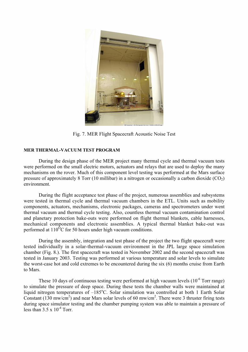
Fig. 7. MER Flight Spacecraft Acoustic Noise Test
MER THERMAL-VACUUM TEST PROGRAM
During the design phase of the MER project many thermal cycle and thermal vacuum testswere performed on the small electric motors, actuators and relays that are used to deploy the manymechanisms on the rover. Much of this component level testing was performed at the Mars surfacepressure of approximately 8 Torr (10 millibar) in a nitrogen or occasionally a carbon dioxide (CO2)environment.
During the flight acceptance test phase of the project, numerous assemblies and subsystemswere tested in thermal cycle and thermal vacuum chambers in the ETL. Units such as mobilitycomponents, actuators, mechanisms, electronic packages, cameras and spectrometers under wentthermal vacuum and thermal cycle testing. Also, countless thermal vacuum contamination controland planetary protection bake-outs were performed on flight thermal blankets, cable harnesses,mechanical components and electronic assemblies. A typical thermal blanket bake-out wasperformed at 110OC for 50 hours under high vacuum conditions.
During the assembly, integration and test phase of the project the two flight spacecraft weretested individually in a solar-thermal-vacuum environment in the JPL large space simulationchamber (Fig. 8.). The first spacecraft was tested in November 2002 and the second spacecraft wastested in January 2003. Testing was performed at various temperature and solar levels to simulatethe worst-case hot and cold extremes to be encountered during the six (6) months cruise from Earthto Mars.
These 10 days of continuous testing were performed at high vacuum levels (10-6 Torr range)to simulate the pressure of deep space. During these tests the chamber walls were maintained atliquid nitrogen temperatures of –185oC. Solar simulation was controlled at both 1 Earth SolarConstant (130 mw/cm2) and near Mars solar levels of 60 mw/cm2. There were 3 thruster firing testsduring space simulator testing and the chamber pumping system was able to maintain a pressure ofless than 3.5 x 10⁻⁴ Torr.
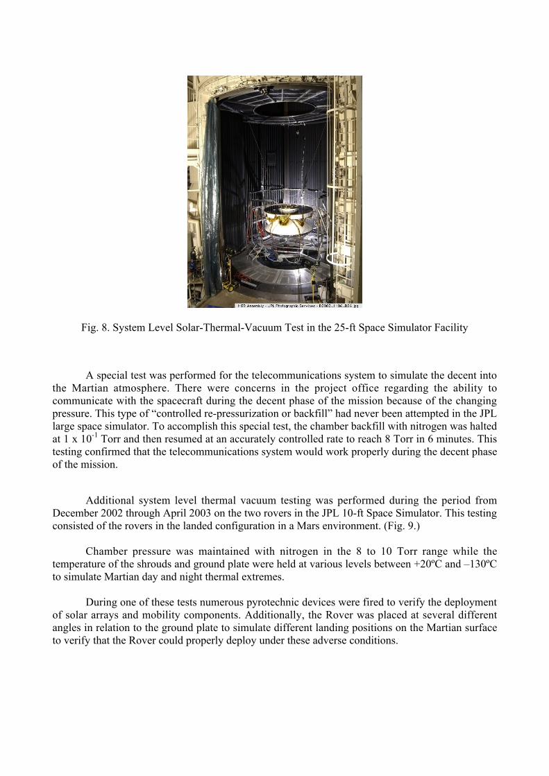
Fig. 8. System Level Solar-Thermal-Vacuum Test in the 25-ft Space Simulator Facility
A special test was performed for the telecommunications system to simulate the decent intothe Martian atmosphere. There were concerns in the project office regarding the ability tocommunicate with the spacecraft during the decent phase of the mission because of the changingpressure. This type of “controlled re-pressurization or backfill” had never been attempted in the JPLlarge space simulator. To accomplish this special test, the chamber backfill with nitrogen was haltedat 1 x 10⁻¹ Torr and then resumed at an accurately controlled rate to reach 8 Torr in 6 minutes. Thistesting confirmed that the telecommunications system would work properly during the decent phaseof the mission.
Additional system level thermal vacuum testing was performed during the period fromDecember 2002 through April 2003 on the two rovers in the JPL 10-ft Space Simulator. This testingconsisted of the rovers in the landed configuration in a Mars environment. (Fig. 9.)
Chamber pressure was maintained with nitrogen in the 8 to 10 Torr range while thetemperature of the shrouds and ground plate were held at various levels between +20ºC and –130ºCto simulate Martian day and night thermal extremes.
During one of these tests numerous pyrotechnic devices were fired to verify the deploymentof solar arrays and mobility components. Additionally, the Rover was placed at several differentangles in relation to the ground plate to simulate different landing positions on the Martian surfaceto verify that the Rover could properly deploy under these adverse conditions.
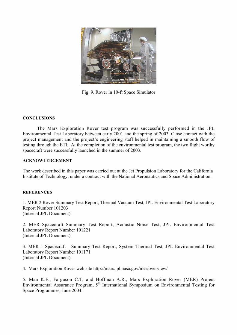
Fig. 9. Rover in 10-ft Space Simulator
CONCLUSIONS
The Mars Exploration Rover test program was successfully performed in the JPLEnvironmental Test Laboratory between early 2001 and the spring of 2003. Close contact with theproject management and the project’s engineering staff helped in maintaining a smooth flow oftesting through the ETL. At the completion of the environmental test program, the two flight worthyspacecraft were successfully launched in the summer of 2003.
ACKNOWLEDGEMENT
The work described in this paper was carried out at the Jet Propulsion Laboratory for the CaliforniaInstitute of Technology, under a contract with the National Aeronautics and Space Administration.
REFERENCES
1. MER 2 Rover Summary Test Report, Thermal Vacuum Test, JPL Environmental Test LaboratoryReport Number 101203(Internal JPL Document)
2. MER Spacecraft Summary Test Report, Acoustic Noise Test, JPL Environmental TestLaboratory Report Number 101221(Internal JPL Document)
3. MER 1 Spacecraft - Summary Test Report, System Thermal Test, JPL Environmental TestLaboratory Report Number 101171(Internal JPL Document)
4. Mars Exploration Rover web site http://mars.jpl.nasa.gov/mer/overview/
5. Man K.F., Farguson C.T, and Hoffman A.R., Mars Exploration Rover (MER) ProjectEnvironmental Assurance Program, 5th International Symposium on Environmental Testing forSpace Programmes, June 2004.
Environmental Test Program forthe Mars Exploration Rover Project
Terry C. FisherPaul L. Van Velzer
5th International Symposium on Environmental Testing for Space Programmes
June 2004
Environmental Test Program forthe Mars Exploration Rover Project
Terry C. FisherPaul L. Van Velzer
23rd Space Simulation ConferenceAnnapolis Maryland
November 2004
Topics
• Mars Exploration Program Overview• Environmental Test Program and Test
Facilities– Vibration– Acoustic– Solar-Thermal-Vacuum
Space Simulation Conference – Annapolis – November 2004

NASA’s Mars Exploration Program
• The Mars Exploration Rover (MER) mission is part of NASA's Mars Exploration Program, a long-term effort of robotic exploration of the red planet. The program seeks to take advantage of each launch opportunity to go to Mars
• Primary among the mission's scientific goals is to search for and characterize a wide range of rocks and soils that hold clues to past water activity on Mars. The MER spacecraft were targeted to sites that appear to have been affected by liquid water in the past
Space Simulation Conference – Annapolis – November 20004
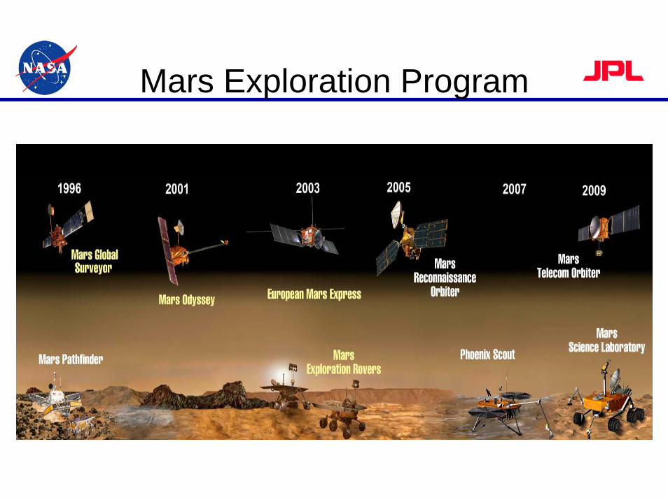
Mars Exploration Program
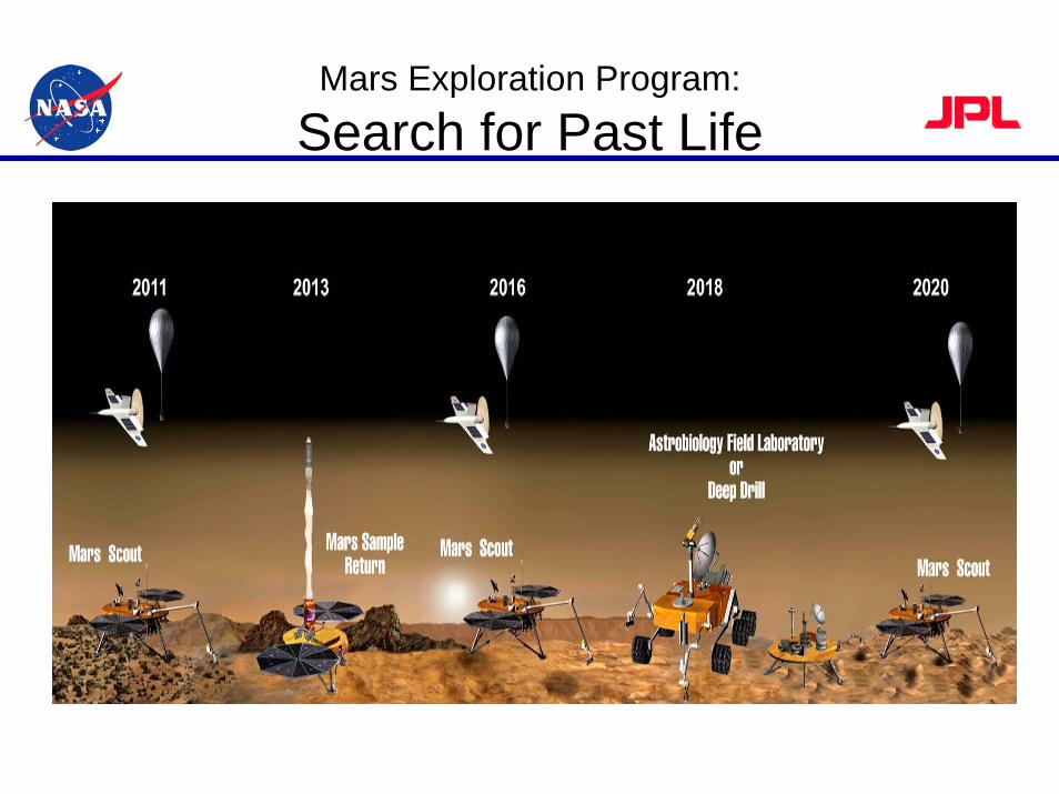
Mars Exploration Program:
Search for Past Life
Mars Exploration Rover Project
• NASA's twin robot geologists, the Mars Exploration Rovers, were launched to Mars in 2003 in search of answers about the history of water on Mars. The first rover, named “Spirit”, landed safely on the surface of Mars on January 3, 2004. The second rover, named “Opportunity”, landed safely on January 24, 2004
• The Mars Exploration Rover (MER) flight system or spacecraft is comprised of the Cruise Stage, the Entry, Descent, and Landing System and the Rover
Space Simulation Conference – Annapolis – November 2004
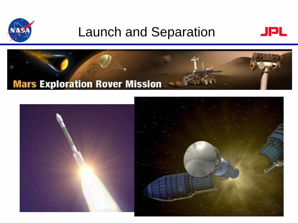
Launch and Separation
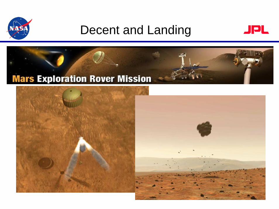
Decent and Landing
Mars Exploration Rover Project• In order to carry out their assigned mission to Mars,
the twin spacecraft were subjected to a comprehensive test program at the Jet Propulsion Laboratory
• The environmental test program included:– Vibration– Landing loads– Solar-Thermal-Vacuum – Pressure variation testing to simulate the decent to the
Martian atmosphere from deep space– Pyro-shock – Thermal-Vacuum testing to simulate the harsh environment
of the planet’s surface
Space Simulation Conference – Annapolis – November 2004
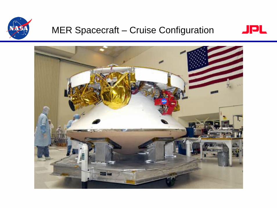
MER Spacecraft – Cruise Configuration
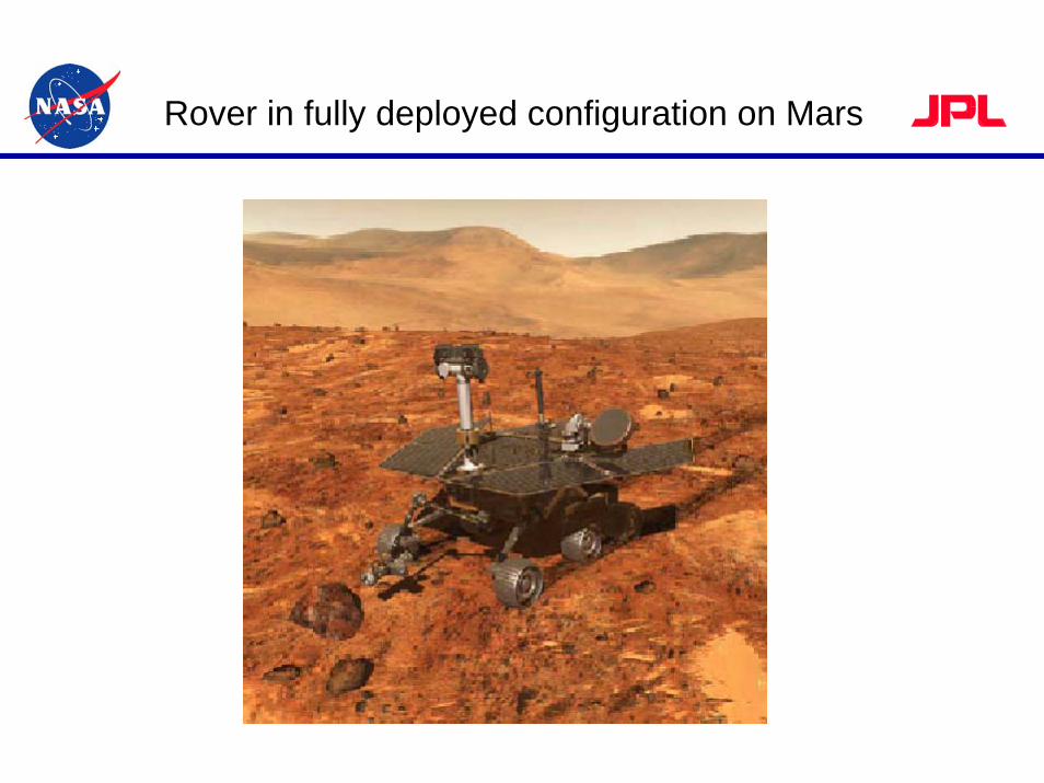
Rover in fully deployed configuration on Mars
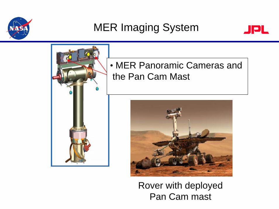
MER Imaging System
• MER Panoramic Cameras and the Pan Cam Mast
Rover with deployed Pan Cam mast
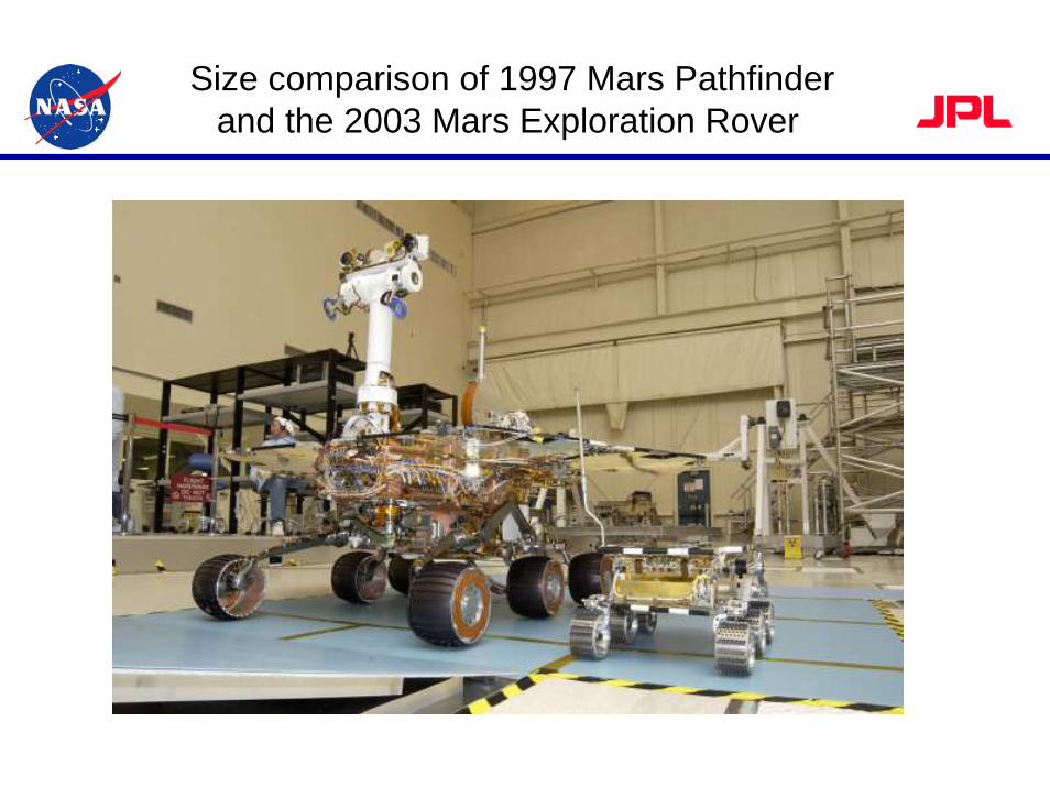
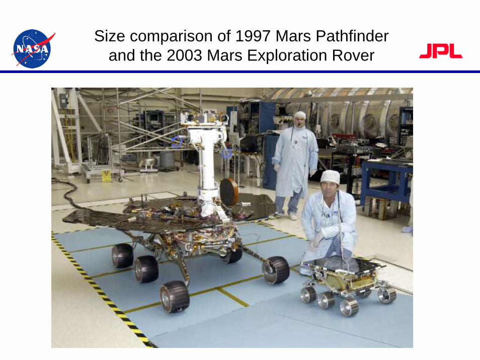
Size comparison of 1997 Mars Pathfinder and the 2003 Mars Exploration Rover
•
Size comparison of 1997 Mars Pathfinderand the 2003 Mars Exploration Rover
Dynamics Test Program
• Development Testing– Landing Loads and Pyro-shock
• Sub-system Testing– Random Vibration
• 5.5 to 8.0 g RMS
• System Level Testing– Random Vibration for Flight System– Random Vibration and Landing Loads for Rover– Acoustic Testing of Flight System
• 145 db
Space Simulation Conference – Annapolis – November 2004
Vibration Test
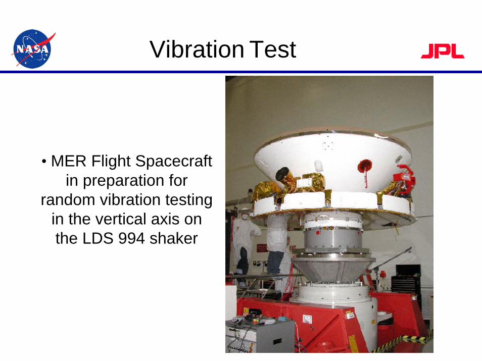
• MER Flight Spacecraft in preparation for
random vibration testing in the vertical axis on the LDS 994 shaker
Vibration Test
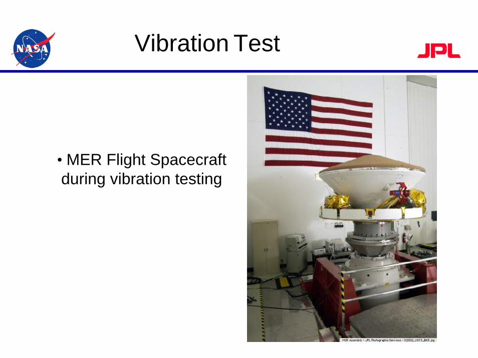
• MER Flight Spacecraft during vibration testing
Vibration Test
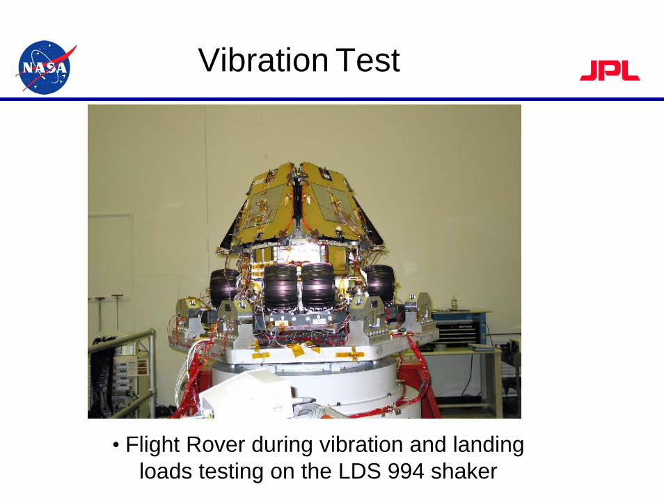
• Flight Rover during vibration and landing loads testing on the LDS 994 shaker
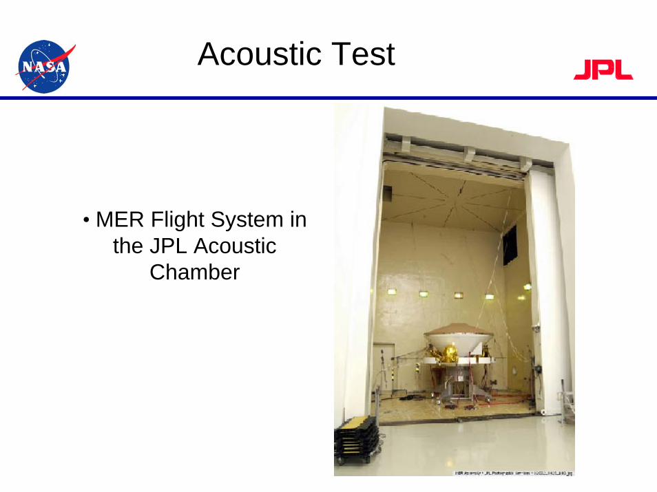
Acoustic Test
• MER Flight System in the JPL Acoustic
Chamber
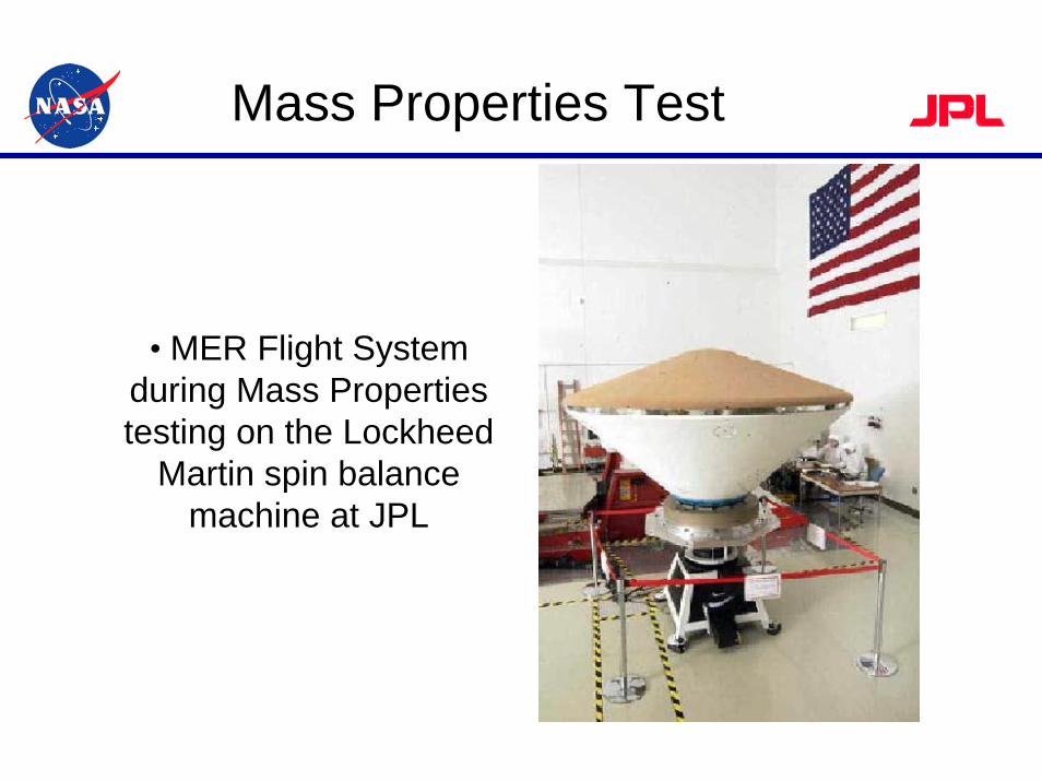
Mass Properties Test
• MER Flight System during Mass Properties testing on the Lockheed
Martin spin balance machine at JPL
Thermal Vacuum Test Program
• Thermal vacuum testing was performed during the design and development phase, at the sub-system level and during the assembly, integration and test phase of the project– High vacuum testing was used to simulate the cruise
phase of the mission between Earth and Mars– Vacuum testing at 8 Torr (10 millibar) in a GN2 or CO2
environment was used to simulate the landed phase of the mission on the surface of Mars
Space Simulation Conference – Annapolis – November 2004
Thermal Vacuum Test Program
• During the design phase of the MER project many thermal cycle and thermal vacuum tests were performed on the small electric motors, actuators and relays that are used to deploy the many mechanisms on the rover – Much of this testing was done at Mars surface
conditions• During the flight acceptance test phase of the project,
numerous assemblies and subsystems were tested in small thermal vacuum chambers at JPL and vendor facilities– Mobility components, actuators, mechanisms,
electronic packages, cameras and spectrometers
Space Simulation Conference – Annapolis – November 2004
Thermal Vacuum Test Program
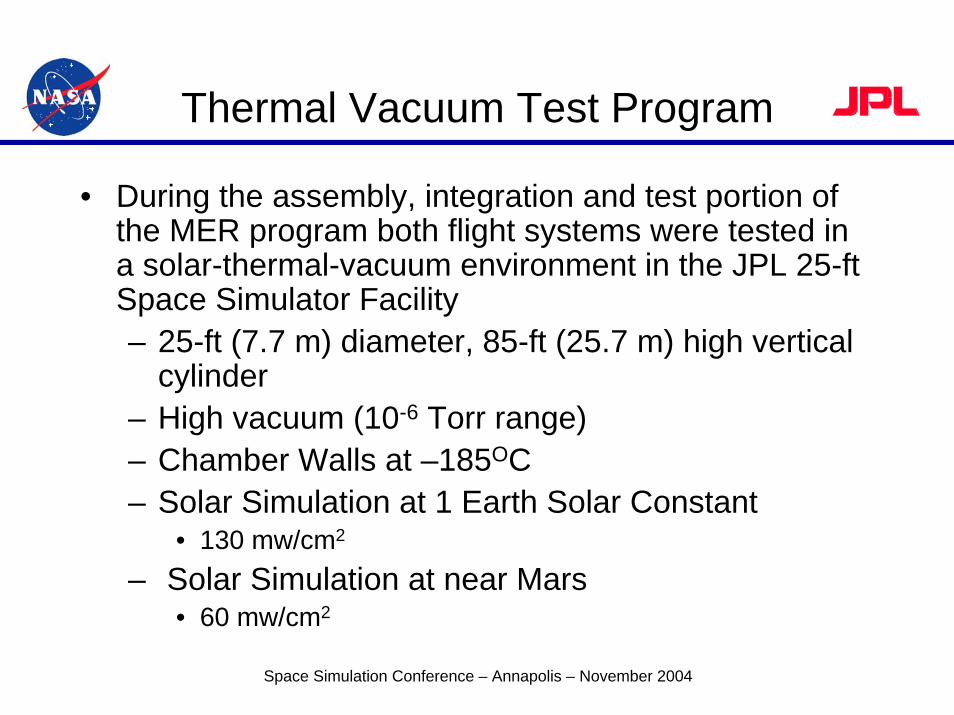
• During the assembly, integration and test portion of the MER program both flight systems were tested in a solar-thermal-vacuum environment in the JPL 25-ft Space Simulator Facility– 25-ft (7.7 m) diameter, 85-ft (25.7 m) high vertical
cylinder– High vacuum (10-6 Torr range)– Chamber Walls at –185OC– Solar Simulation at 1 Earth Solar Constant
• 130 mw/cm2
– Solar Simulation at near Mars• 60 mw/cm2
Space Simulation Conference – Annapolis – November 2004
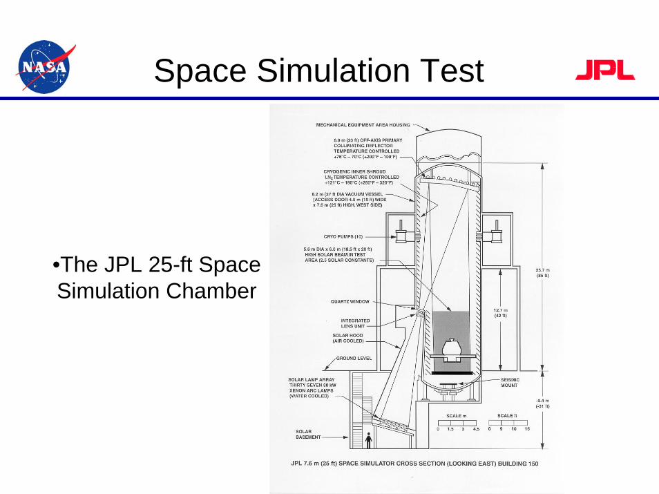
Space Simulation Test
•The JPL 25-ft Space Simulation Chamber
Space Simulation Test
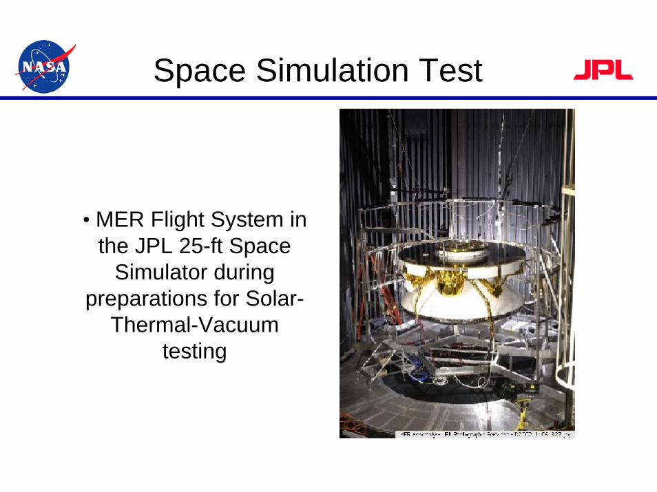
• MER Flight System in the JPL 25-ft Space
Simulator during preparations for Solar-
Thermal-Vacuum testing
Space Simulation Test
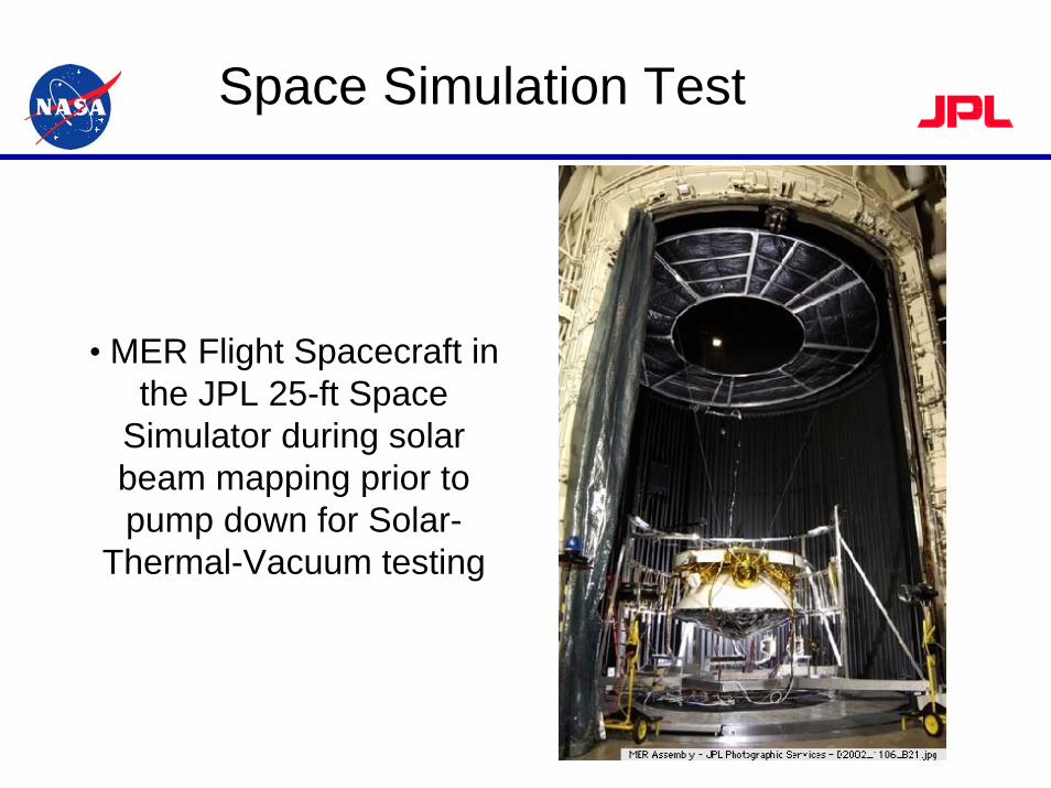
• MER Flight Spacecraft in the JPL 25-ft Space
Simulator during solar beam mapping prior to pump down for Solar-
Thermal-Vacuum testing
Thermal Vacuum Test Program
• Special testing was performed in the large JPL chambers to simulate the decent into the Martian atmosphere from deep space– The purpose was to confirm the ability to communicate
with the spacecraft’s telecommunications system during the decent phase
• This type of “controlled re-pressurization or backfill”had never been attempted in the JPL large space simulator– To accomplish this special test, the chamber backfill
with nitrogen was halted at 1 x 10⁻¹ Torr and then resumed at an accurately controlled rate to reach 8 Torr in exactly 6 minutes
Space Simulation Conference – Annapolis – November 2004
Space Simulation Test
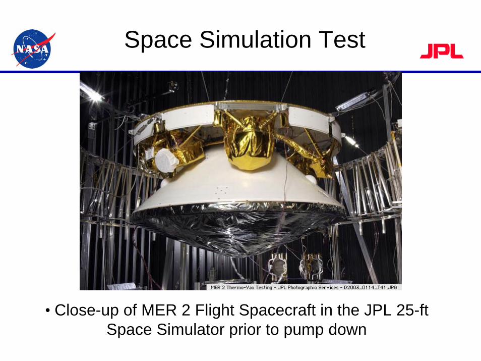
• Close-up of MER 2 Flight Spacecraft in the JPL 25-ft Space Simulator prior to pump down
Thermal Vacuum Test Program
• Also during the assembly, integration and test portion of the MER program both flight Rovers were tested in a thermal-vacuum environment in the JPL 10-ft Space Simulator Facility – 10-ft (3 m) diameter, 45-ft (13.7 m) vertical cylinder
• This testing consisted of the Rover in the landed configuration in a Mars environment– Chamber pressure was maintained with nitrogen in the
8 to 10 Torr (10 millibar) range– Temperature of the shrouds and ground plate were
held at various levels between –130OC and +20OC to simulate Martian night and day thermal extremes
Space Simulation Conference – Annapolis – November 2004
Space Simulation Test
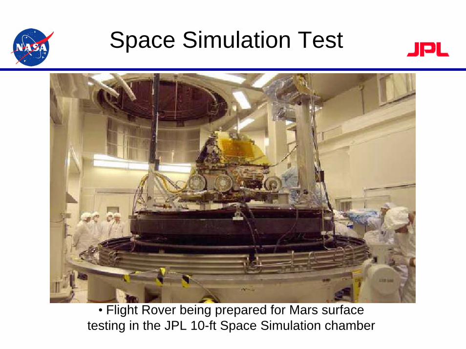
• Flight Rover being prepared for Mars surface testing in the JPL 10-ft Space Simulation chamber
Thermal Vacuum Test Program
• During one test numerous pyrotechnic devices were fired to verify the deployment of solar arrays and mobility components in the simulated Mars surface environment
• During other test runs the Rover was placed at several different angles in relation to the ground plate to simulate different landing positions on the Martian surface to verify that the Rover could properly deploy under these adverse conditions
Space Simulation Conference – Annapolis – November 2004
Space Simulation Test
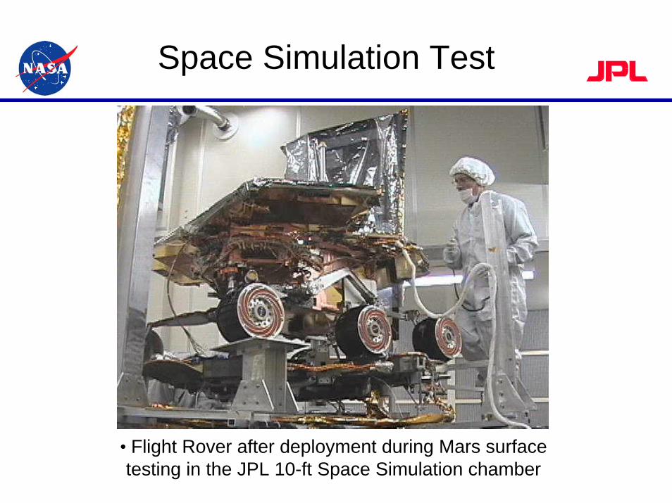
• Flight Rover after deployment during Mars surface testing in the JPL 10-ft Space Simulation chamber
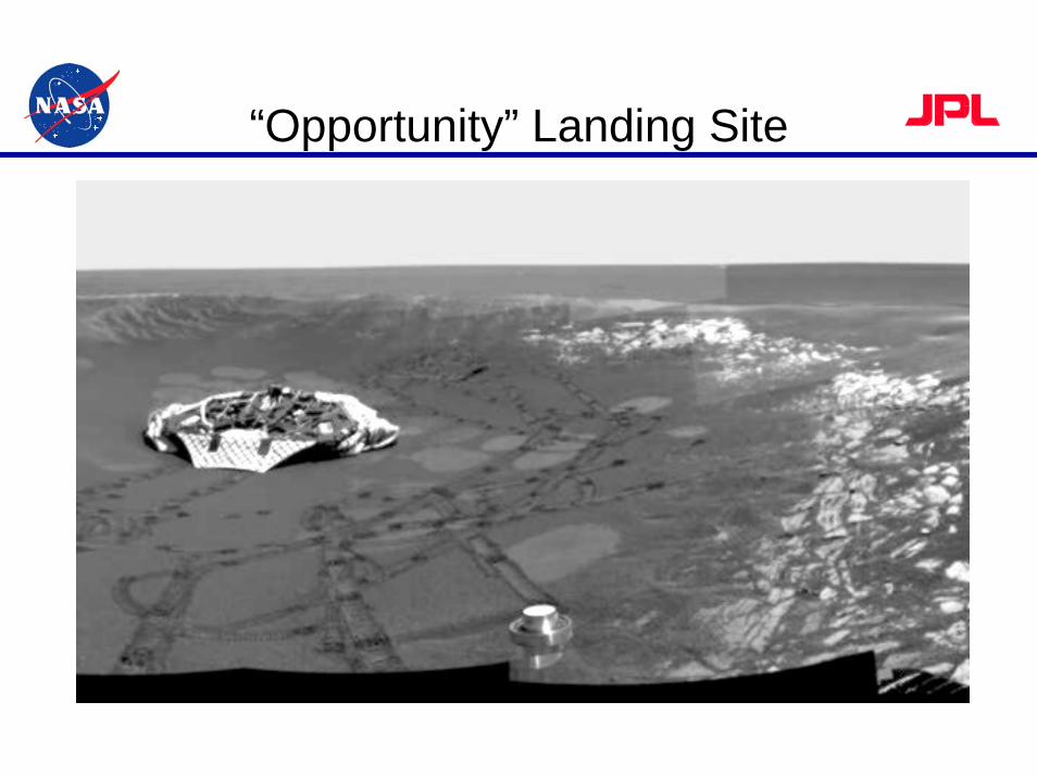
“Opportunity” Landing Site
Conclusions
• The Mars Exploration Rover test campaign was successfully performed in the JPL Environmental Test Laboratory between early 2001 and the spring of 2003– Close contact with the project management and the
project’s engineering staff helped in maintaining a smooth flow of testing through the ETL
• At the completion of the environmental test program, the two flight worthy spacecraft were successfully launched in the summer of 2003
Space Simulation Conference – Annapolis – November 2004