Embed Size (px)
Citation preview
TITLE SHEET 1933.ID
© Darden Architects, Inc. 000101 - 1 5/31/2019 1:44 PM
PROJECT MANUAL FOR
MERCED COLLEGE NEXTUP (a.k.a. BID 2019-02 NEXT UP PROGRAM REMODEL)
INTERIOR DESIGNER:
MERCED COMMUNITY COLLEGE DISTRICT
3600 M STREET
MERCED, CA 95348-2898
PREPARED BY:
DARDEN ARCHITECTS, INC.
ARCHITECTURE•PLANNING•INTERIORS
6790 N. WEST AVENUE
FRESNO, CALIFORNIA 93711
END OF SECTION

PROJECT MANUAL TABLE OF CONTENTS 1933.ID
© Darden Architects, Inc. 00 01 11 - 1 Last printed 5/31/2019 11:29 AM
PROJECT MANUAL
TABLE OF CONTENTS
PROCUREMENT AND CONTRACTING REQUIREMENTS GROUP
DIVISION 00 - PROCUREMENT AND CONTRACTING REQUIREMENTS
INTRODUCTORY INFORMATION
00 01 01 PROJECT TITLE PAGE .................................................................................................................. 1
00 01 11 PROJECT MANUAL TABLE OF CONTENTS .............................................................................. 2
00 23 13.03 SUPPLEMENTARY INSTRUCTIONS FOR BIDDERS ................................................................ 8
PROCUREMENT REQUIREMENTS, FORMS AND SUPPLEMENTS, CONTRACTING FORMS AND
SUPLEMENTS, AND GENERAL CONDITIONS
00 30 00 OWNER’S BID AND CONTRACTING DOCUMENTS ............................................................ 126
SPECIFICATIONS GROUP
GENERAL REQUIREMENTS SUBGROUP
DIVISION 01 – GENERAL REQUIREMENTS SUBSTITUTION PROCEDURES
01 25 00 SUBSTITUTION PROCEDURES ................................................................................................... 6
SUBMITTAL PROCEDURES
01 33 00 SUBMITTAL PROCEDURES ....................................................................................................... 11
EXECUTION AND CLOSEOUT REQUIREMENTS
01 73 29 CUTTING AND PATCHING .......................................................................................................... 4
01 77 20 PROJECT CLOSEOUT .................................................................................................................... 7
01 78 36 WARRANTIES ................................................................................................................................ 3
FACILITY CONSTRUCTION SUBGROUP
DIVISION 02 – EXISTING CONDITIONS 02 41 19 SELECTIVE DEMOLITION ........................................................................................................... 7
DIVISION 03 – CONCRETE 03 11 01 CONCRETE FORMWORK ............................................................................................................. 7
03 15 14 DRILLED ANCHORS ...................................................................................................................... 7
03 20 00 REINFORCEMENT ......................................................................................................................... 8
03 30 00 CAST-IN-PLACE CONCRETE ..................................................................................................... 23
DIVISION 04 – NOT USED
DIVISION 05 – METALS 05 12 00 STEEL AND FABRICATIONS ..................................................................................................... 11
PROJECT MANUAL TABLE OF CONTENTS 1933.ID
© Darden Architects, Inc. 00 01 11 - 2 Last printed 5/31/2019 11:29 AM
DIVISION 06 – WOOD, PLASTICS, AND COMPOSITES 06 10 00 ROUGH CARPENTRY .................................................................................................................. 12
06 41 23 MODULAR CASEWORK ............................................................................................................. 12
DIVISION 08 – OPENINGS 08 14 16 WOOD DOORS ................................................................................................................................ 8
08 41 00 STOREFRONTS ............................................................................................................................. 14
08 80 00 GLASS ............................................................................................................................................ 13
DIVISION 09 – FINISHES 09 22 16 METAL FRAMING ........................................................................................................................ 11
09 29 00 GYPSUM BOARD ......................................................................................................................... 14
09 50 00 ACOUSTICAL CEILINGS ............................................................................................................ 13
09 65 10 RESILIENT BASE AND ACCESSORIES ...................................................................................... 8
09 65 19 RESILIENT TILE ............................................................................................................................. 8
09 91 00 PAINTING ...................................................................................................................................... 25
DIVISION 10 – SPECIALTIES 10 05 00 MISCELLANEOUS SPECIALTIES ................................................................................................ 4
(See specification section for miscellaneous products, systems or design specified)
DIVISION 11 – 19 – NOT USED
FACILITY SERVICES SUBGROUP – NOT USED
SITE AND INFRASTRUCTURE SUBGROUP – NOT USED
PROCESS EQUIPMENT SUBGROUP – NOT USED
END OF SECTION
SUPPLEMENTARY INSTRUCTIONS TO BIDDERS
1933.ID
SECTION 002213.03 – SUPPLEMENTARY INSTRUCTIONS TO BIDDERS
PART 1 - GENERAL
1.1 SUMMARY
A. This Section includes the following:1. Supplementary Instructions to Bidders consisting of procedures and conditions for the
use of documents of various types and formats for bidding of this project.
B. Related Sections: The following Project Manual Sections contain requirements that relate to this section:1. ALL DIVISION 00 SPECIFICATION SECTIONS.2. ALL DIVISION 01 SPECIFICATION SECTIONS.3. ALL SPECIFICATION SECTIONS IN THE FACILITY SERVICES SUBGROUP.4. ALL SPECIFICATION SECTIONS IN THE SITE AND INFRASTRUCTURE
SUBGROUP.
1.2 DEFINITIONS
A. Hard Copy Format: Documents printed on paper medium.
B. Electronic Image Format: Electronic Files consisting of Bid Documents in an image format such as PDF's, TIFF's and etc. These files are to be READ ONLY.
1.3 SUBMITTALS
A. Submit in accordance with the following:1. Bidder's Usage Agreement for Bid Documents:
a. Hard Copy Format Form.b. Hard Copy and Electronic Image Format Form.
2. Bidder's Usage Agreement for Partial Documents. a. Partial Bid Documents Form.
PART 2 - PRODUCTS(NOT APPLICABLE)
PART 3 - EXECUTION
3.1 SCHEDULES:
A. BIDDER'S USAGE AGREEMENT FOR BID DOCUMENTS:
002213.03 - 1 05/28/2019
SUPPLEMENTARY INSTRUCTIONS TO BIDDERS
1933.ID
1. HARD COPY FORMAT: When the Bid Documents are being issued in a printed medium, the HARD COPY FORMAT FORM shall be used. a. This form shall be submitted and signed as a condition of receiving Bid
Documents.2. HARD COPY AND ELECTRONIC IMAGE FORMAT: When the Bid Documents are
being issued electronically, the HARD COPY AND ELECTRONIC IMAGE FORMAT FORM shall be used. a. This form shall be submitted and signed as a condition of receiving Bid
Documents.
B. BIDDER'S USAGE AGREEMENT FOR PARTIAL BID DOCUMENTS.1. When the Bidder is requesting additional documents which are part of the Bid
Documents, the PARTIAL BID DOCUMENTS FORM shall be used. a. This form shall be submitted and signed as a condition of receiving Partial Bid
Documents.
002213.03 - 2 05/28/2019
SUPPLEMENTARY INSTRUCTIONS TO BIDDERS
1933.ID
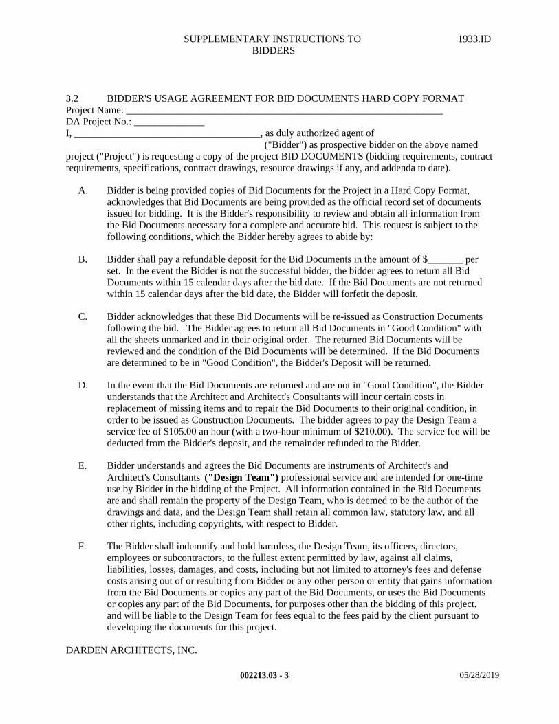
3.2 BIDDER'S USAGE AGREEMENT FOR BID DOCUMENTS HARD COPY FORMATProject Name: _______________________________________________________________DA Project No.: ______________I, _____________________________________, as duly authorized agent of_______________________________________ ("Bidder") as prospective bidder on the above named project ("Project") is requesting a copy of the project BID DOCUMENTS (bidding requirements, contract requirements, specifications, contract drawings, resource drawings if any, and addenda to date).
A. Bidder is being provided copies of Bid Documents for the Project in a Hard Copy Format, acknowledges that Bid Documents are being provided as the official record set of documents issued for bidding. It is the Bidder's responsibility to review and obtain all information from the Bid Documents necessary for a complete and accurate bid. This request is subject to the following conditions, which the Bidder hereby agrees to abide by:
B. Bidder shall pay a refundable deposit for the Bid Documents in the amount of $_______ per set. In the event the Bidder is not the successful bidder, the bidder agrees to return all Bid Documents within 15 calendar days after the bid date. If the Bid Documents are not returned within 15 calendar days after the bid date, the Bidder will forfetit the deposit.
C. Bidder acknowledges that these Bid Documents will be re-issued as Construction Documents following the bid. The Bidder agrees to return all Bid Documents in "Good Condition" with all the sheets unmarked and in their original order. The returned Bid Documents will be reviewed and the condition of the Bid Documents will be determined. If the Bid Documents are determined to be in "Good Condition", the Bidder's Deposit will be returned.
D. In the event that the Bid Documents are returned and are not in "Good Condition", the Bidder understands that the Architect and Architect's Consultants will incur certain costs in replacement of missing items and to repair the Bid Documents to their original condition, in order to be issued as Construction Documents. The bidder agrees to pay the Design Team a service fee of $105.00 an hour (with a two-hour minimum of $210.00). The service fee will be deducted from the Bidder's deposit, and the remainder refunded to the Bidder.
E. Bidder understands and agrees the Bid Documents are instruments of Architect's and Architect's Consultants' ("Design Team") professional service and are intended for one-time use by Bidder in the bidding of the Project. All information contained in the Bid Documents are and shall remain the property of the Design Team, who is deemed to be the author of the drawings and data, and the Design Team shall retain all common law, statutory law, and all other rights, including copyrights, with respect to Bidder.
F. The Bidder shall indemnify and hold harmless, the Design Team, its officers, directors, employees or subcontractors, to the fullest extent permitted by law, against all claims, liabilities, losses, damages, and costs, including but not limited to attorney's fees and defense costs arising out of or resulting from Bidder or any other person or entity that gains information from the Bid Documents or copies any part of the Bid Documents, or uses the Bid Documents or copies any part of the Bid Documents, for purposes other than the bidding of this project, and will be liable to the Design Team for fees equal to the fees paid by the client pursuant to developing the documents for this project.
DARDEN ARCHITECTS, INC.
002213.03 - 3 05/28/2019
SUPPLEMENTARY INSTRUCTIONS TO BIDDERS
1933.ID
Number of Sets Requested:______________________________________________
______________________________________ __________________Print Name (Bidder) Title
______________________________________ ___________________Signature Date:
002213.03 - 4 05/28/2019
SUPPLEMENTARY INSTRUCTIONS TO BIDDERS
1933.ID
3.3 BIDDER'S USAGE AGREEMENT FOR BID DOCUMENTS HARD COPY AND ELECTRONIC IMAGE FORMAT
Project Name: _______________________________________________________________DA Project No.: ______________I, _____________________________________, as duly authorized agent of_______________________________________ ("Bidder") as prospective bidder on the above named project ("Project") is requesting a copy of the project BID DOCUMENTS (bidding requirements, contract requirements, specifications, contract drawings, resource drawings if any, and addenda to date).
A. Bidder is being provided copies of Bid Documents for the Project, which consists of two parts. One part of the Bid Documents is in the Hard Copy Format ("HCF") and the other part is in the Electronic Image Format ("EIF") on CD-ROM. Bidder acknowledges that HCF Documents and the EIF Documents are being provided as the official record set of documents issued for bidding. It is the Bidder's responsibility to review and obtain all information from both the HCF and the EIF documents necessary for a complete and accurate bid. This request is subject to the following conditions, which the Bidder hereby agrees to abide by:
B. Bidder shall pay a non-refundable deposit for the Bid Documents in the amount of $_______. In the event the Bidder is not the successful bidder, the bidder agrees to permanently dispose of the HCF and EIF on the Project CD-ROM.
C. Bidder acknowledges that neither the EIF documents nor the CD-ROM will be updated by the Design Team. The CD-ROM contains the original documents and will not be updated regardless of when Bidder obtains the CD-ROM. Any changes to the contract documents will be issued as a separate document.
D. Bidder is further warned that while the EIF information appears to be extremely accurate, this apparent accuracy is an artifact of the techniques used to generate it and is no way intended to imply actual accuracy. The Bidder acknowledges and takes full responsibility for the accuracy, correctness of measurements, areas, inventories derived, conclusions drawn, and information extracted from the EIF documents.
E. Bidder understands and agrees the HCF and EIF documents are instruments of Architect's and Architect's Consultants' ("Design Team") professional service and are intended for one-time use by Bidder in the bidding of the Project. All HCF and EIF documents are and shall remain the property of the Design Team, who is deemed to be the author of the drawings and data, and the Design Team shall retain all common law, statutory law, and all other rights, including copyrights, with respect to Bidder.
F. The Bidder shall indemnify and hold harmless, the Design Team, its officers, directors, employees or subcontractors, to the fullest extent permitted by law, against all claims, liabilities, losses, damages, and costs, including but not limited to attorney's fees and defense costs arising out of or resulting from Bidder or any other person or entity that gains information from the Bid Documents or copies any part of the Bid Documents, or uses the Bid Documents or copies any part of the Bid Documents, for purposes other than the bidding of this project, and will be liable to the Design Team for fees equal to the fees paid by the client pursuant to developing the documents for this project.
DARDEN ARCHITECTS, INC.
002213.03 - 5 05/28/2019
SUPPLEMENTARY INSTRUCTIONS TO BIDDERS
1933.ID
Description of the HCF Documents and the EIF Documents on CD-ROM, provided:___________________________________________________________________________________________________________________________________________________________________________________________________________________________________________________________________________ _________________________Print Name (Bidder) Title__________________________________________ _________________________Signature Date:
002213.03 - 6 05/28/2019
SUPPLEMENTARY INSTRUCTIONS TO BIDDERS
1933.ID
3.4 BIDDER'S USAGE AGREEMENT FOR PARTIAL BID DOCUMENTSProject Name: __________________________________________________ DA Project No.: _______________________________I, _____________________________________, as duly authorized agent of_______________________________________ ("Bidder") as prospective bidder on the above named project ("Project"). The Bidder acknowledge having received at least one (1) complete set of the Bid Documents for the subject project and all Addenda issued to date in either Hard Copy Format ("HCF") and/or an Electronic Image Format ("EIF").
A. The Bidder is requesting partial copies of the Bid Documents ("Partial Documents") in the format originally issued and that was prepared by the Architect and/or Architect's Consultants ("Design Team") on the subject Project, so that the information therein may be utilized in the Bidder's work on the same project. The Partial Documents are strictly intended for the Bidder's convenience and are not recognized as part of the official record set of Bid Documents issued for bidding. This request is subject to the following conditions, which the Bidder hereby agrees to abide by:
B. The Bidder shall pay for all costs in reproducing the requested Partial Documents directly to the Printers. In the event that the Bidder is not the successful bidder, the Bidder agrees to permanently dispose of the Partial Documents.
C. The Bidder recognizes that the value of the Partial Documents far exceeds the cost of printing. The Bidder further agrees that the Bidder will make no other copies of the Partial Documents. Any copying, and/or reuse of the Partial Documents without written authorization of Darden Architects, Inc. is prohibited.
D. The Bidder understands that the accuracy of the information is an artifact of the techniques used to generate it and is in no way intended to imply actual accuracy. The Bidder agrees that by using these Partial Documents, the Bidder is in no way relieved of the responsibility to review and obtain all information from the complete set of the Bid Documents necessary for a complete and accurate bid.
E. The Bidder understands and agrees to that any documents provided are instruments of the professional service by the Design Team and are intended for one-time use solely in the bidding of this Project. They shall remain the property of the Architect or the Architect's Consultants, who is deemed to be the author of the documents and who shall retain all common law, statutory law, and all other rights, including copyrights, with respect to the Bidder.
F. The Bidder shall indemnify and hold harmless, the Design Team, its officers, directors, employees or subcontractors, to the fullest extent permitted by law, against all claims, liabilities, losses, damages, and costs, including but not limited to attorney's fees and defense costs arising out of or resulting from Bidder or any other person or entity that gains information from the Partial Documents or copies the Partial Documents, or uses the Partial Documents or copies the Partial Documents, for purposes other than the bidding of this project, and will be liable to Design Team for fees equal to the fees paid by the client pursuant to developing the documents for this project.
002213.03 - 7 05/28/2019
SUPPLEMENTARY INSTRUCTIONS TO BIDDERS
1933.ID
G. In the event that the Bidder is a successful bidder, the Bidder agrees that all Bid Documents issued to the Bidder, and Partial Documents obtained by the Bidder, along with any other documents utilized by the Bidder in preparing the bid, will be included in the Escrow Bid Documents when required by the General Conditions. Any and all documents prepared and issued by the Design Team, which are included as part of the Escrow Bid Documents, will be returned to Darden Architects, Inc. at the close of escrow.
DARDEN ARCHITECTS, INC.
Description of the requested documents:_____________________________________________________________________________________________________________________________________________________________________________________________________________________________________________________________________________________________________________________________________________________________________________________________________________________________________________________________________________________________________________ _________________________Print Name, (Bidder) Title_____________________________________ _________________________Signature Dated:
END OF SECTION
002213.03 - 8 05/28/2019
Merced Community College District
Long Form; Rev. June, 2018 Page|1 Table of Contents NEXT UP PROGRAM REMODEL
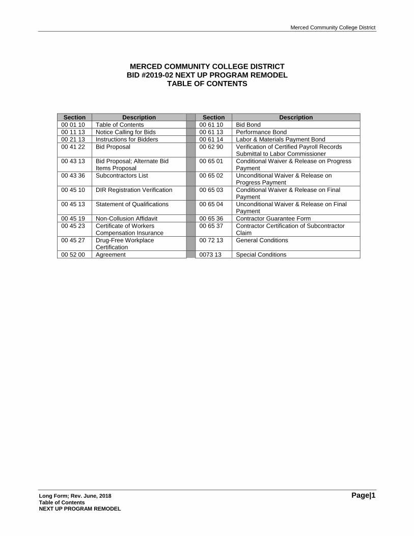
MERCED COMMUNITY COLLEGE DISTRICT
BID #2019-02 NEXT UP PROGRAM REMODEL TABLE OF CONTENTS
Section Description Section Description
00 01 10 Table of Contents 00 61 10 Bid Bond
00 11 13 Notice Calling for Bids 00 61 13 Performance Bond
00 21 13 Instructions for Bidders 00 61 14 Labor & Materials Payment Bond
00 41 22 Bid Proposal 00 62 90 Verification of Certified Payroll Records Submittal to Labor Commissioner
00 43 13 Bid Proposal; Alternate Bid Items Proposal
00 65 01 Conditional Waiver & Release on Progress Payment
00 43 36 Subcontractors List 00 65 02 Unconditional Waiver & Release on Progress Payment
00 45 10 DIR Registration Verification 00 65 03 Conditional Waiver & Release on Final Payment
00 45 13 Statement of Qualifications 00 65 04 Unconditional Waiver & Release on Final Payment
00 45 19 Non-Collusion Affidavit 00 65 36 Contractor Guarantee Form
00 45 23 Certificate of Workers Compensation Insurance
00 65 37 Contractor Certification of Subcontractor Claim
00 45 27 Drug-Free Workplace Certification
00 72 13 General Conditions
00 52 00 Agreement 0073 13 Special Conditions
Merced Community College District
Long Form; Rev. June, 2018 Page|2 NEXT UP PROGRAM REMODEL
THIS PAGE INTENTIONALLY BLANK
Merced Community College District
Long Form; Rev. June, 2018 Page|3 Call for Bids; Section 00 11 13 Next Up Program Remodel
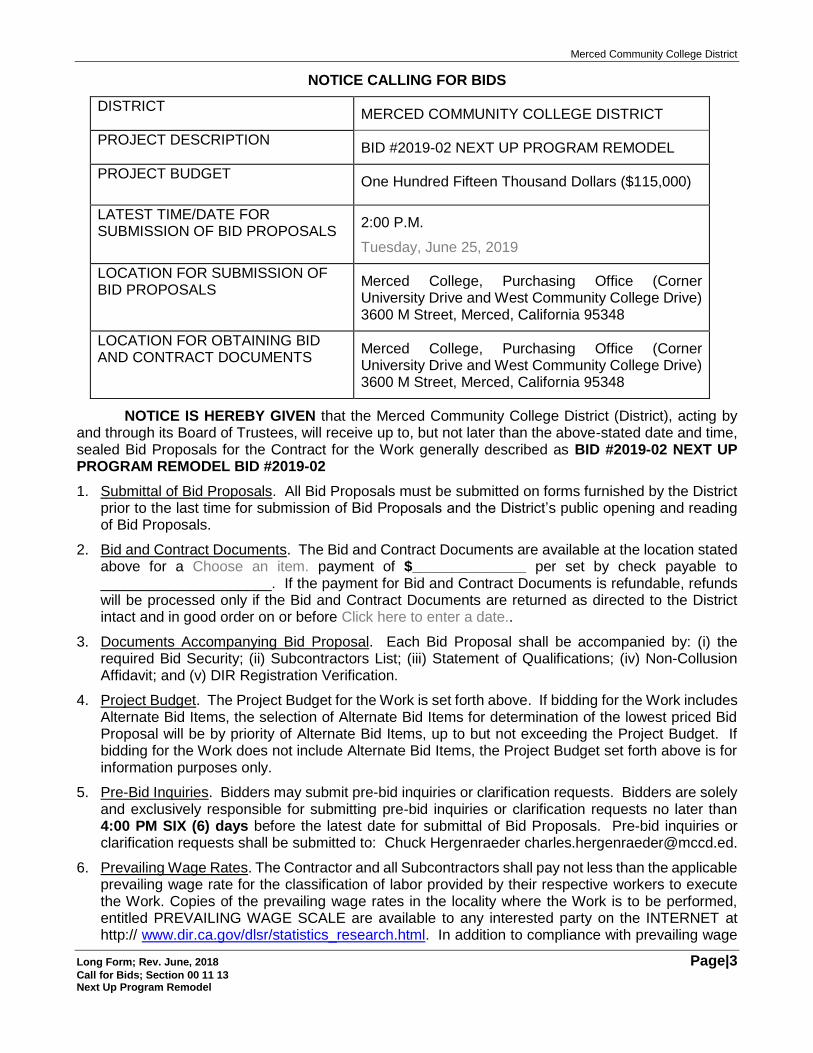
NOTICE CALLING FOR BIDS
DISTRICT MERCED COMMUNITY COLLEGE DISTRICT
PROJECT DESCRIPTION BID #2019-02 NEXT UP PROGRAM REMODEL
PROJECT BUDGET One Hundred Fifteen Thousand Dollars ($115,000)
LATEST TIME/DATE FOR SUBMISSION OF BID PROPOSALS
2:00 P.M.
Tuesday, June 25, 2019
LOCATION FOR SUBMISSION OF BID PROPOSALS
Merced College, Purchasing Office (Corner University Drive and West Community College Drive) 3600 M Street, Merced, California 95348
LOCATION FOR OBTAINING BID AND CONTRACT DOCUMENTS
Merced College, Purchasing Office (Corner University Drive and West Community College Drive) 3600 M Street, Merced, California 95348
NOTICE IS HEREBY GIVEN that the Merced Community College District (District), acting by and through its Board of Trustees, will receive up to, but not later than the above-stated date and time, sealed Bid Proposals for the Contract for the Work generally described as BID #2019-02 NEXT UP PROGRAM REMODEL BID #2019-02
1. Submittal of Bid Proposals. All Bid Proposals must be submitted on forms furnished by the District prior to the last time for submission of Bid Proposals and the District’s public opening and reading of Bid Proposals.
2. Bid and Contract Documents. The Bid and Contract Documents are available at the location stated above for a Choose an item. payment of $______________ per set by check payable to _____________________. If the payment for Bid and Contract Documents is refundable, refunds will be processed only if the Bid and Contract Documents are returned as directed to the District intact and in good order on or before Click here to enter a date..
3. Documents Accompanying Bid Proposal. Each Bid Proposal shall be accompanied by: (i) the required Bid Security; (ii) Subcontractors List; (iii) Statement of Qualifications; (iv) Non-Collusion Affidavit; and (v) DIR Registration Verification.
4. Project Budget. The Project Budget for the Work is set forth above. If bidding for the Work includes Alternate Bid Items, the selection of Alternate Bid Items for determination of the lowest priced Bid Proposal will be by priority of Alternate Bid Items, up to but not exceeding the Project Budget. If bidding for the Work does not include Alternate Bid Items, the Project Budget set forth above is for information purposes only.
5. Pre-Bid Inquiries. Bidders may submit pre-bid inquiries or clarification requests. Bidders are solely and exclusively responsible for submitting pre-bid inquiries or clarification requests no later than 4:00 PM SIX (6) days before the latest date for submittal of Bid Proposals. Pre-bid inquiries or clarification requests shall be submitted to: Chuck Hergenraeder [email protected].
6. Prevailing Wage Rates. The Contractor and all Subcontractors shall pay not less than the applicable prevailing wage rate for the classification of labor provided by their respective workers to execute the Work. Copies of the prevailing wage rates in the locality where the Work is to be performed, entitled PREVAILING WAGE SCALE are available to any interested party on the INTERNET at http:// www.dir.ca.gov/dlsr/statistics_research.html. In addition to compliance with prevailing wage
Merced Community College District
Long Form; Rev. June, 2018 Page|4 Call for Bids; Section 00 11 13 Next Up Program Remodel
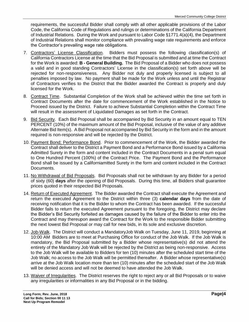
requirements, the successful Bidder shall comply with all other applicable provisions of the Labor Code, the California Code of Regulations and rulings or determinations of the California Department of Industrial Relations. During the Work and pursuant to Labor Code §1771.4(a)(4), the Department of Industrial Relations shall monitor compliance with prevailing wage rate requirements and enforce the Contractor’s prevailing wage rate obligations.
7. Contractors’ License Classification. Bidders must possess the following classification(s) of California Contractors License at the time that the Bid Proposal is submitted and at time the Contract for the Work is awarded: B - General Building. The Bid Proposal of a Bidder who does not possess a valid and in good standing Contractors’ License in the classification(s) set forth above will be rejected for non-responsiveness. Any Bidder not duly and properly licensed is subject to all penalties imposed by law. No payment shall be made for the Work unless and until the Registrar of Contractors verifies to the District that the Bidder awarded the Contract is properly and duly licensed for the Work.
8. Contract Time. Substantial Completion of the Work shall be achieved within the time set forth in Contract Documents after the date for commencement of the Work established in the Notice to Proceed issued by the District. Failure to achieve Substantial Completion within the Contract Time will result in the assessment of Liquidated Damages as set forth in the Contract.
9. Bid Security. Each Bid Proposal shall be accompanied by Bid Security in an amount equal to TEN PERCENT (10%) of the maximum amount of the Bid Proposal, inclusive of the value of any additive Alternate Bid Item(s). A Bid Proposal not accompanied by Bid Security in the form and in the amount required is non-responsive and will be rejected by the District.
10. Payment Bond; Performance Bond. Prior to commencement of the Work, the Bidder awarded the Contract shall deliver to the District a Payment Bond and a Performance Bond issued by a California Admitted Surety in the form and content included in the Contract Documents in a penal sum equal to One Hundred Percent (100%) of the Contract Price. The Payment Bond and the Performance Bond shall be issued by a Californiamitted Surety in the form and content included in the Contract Documents.
11. No Withdrawal of Bid Proposals. Bid Proposals shall not be withdrawn by any Bidder for a period of sixty (60) days after the opening of Bid Proposals. During this time, all Bidders shall guarantee prices quoted in their respected Bid Proposals.
14. Return of Executed Agreement. The Bidder awarded the Contract shall execute the Agreement and return the executed Agreement to the District within three (3) calendar days from the date of receiving notification that it is the Bidder to whom the Contract has been awarded. If the successful Bidder fails to return the executed Agreement pursuant to the foregoing, the District may declare the Bidder’s Bid Security forfeited as damages caused by the failure of the Bidder to enter into the Contract and may thereupon award the Contract for the Work to the responsible Bidder submitting the next lowest Bid Proposal or may call for new bids, in its sole and exclusive discretion.
12. Job-Walk. The District will conduct a MandatoryJob Walk on Tuesday, June 11, 2019, beginning at 10:00 AM Bidders are to meet at Purchasing Office for conduct of the Job Walk. If the Job Walk is mandatory, the Bid Proposal submitted by a Bidder whose representative(s) did not attend the entirety of the Mandatory Job Walk will be rejected by the District as being non-responsive. Access to the Job Walk will be available to Bidders for ten (10) minutes after the scheduled start time of the Job Walk; no access to the Job Walk will be permitted thereafter. A Bidder whose representative(s) arrive at the Job Walk location more than ten (10) minutes after the scheduled start of the Job Walk will be denied access and will not be deemed to have attended the Job Walk.
13. Waiver of Irregularities. The District reserves the right to reject any or all Bid Proposals or to waive any irregularities or informalities in any Bid Proposal or in the bidding.
Merced Community College District
Long Form; Rev. June, 2018 Page|5 Call for Bids; Section 00 11 13 Next Up Program Remodel
14. Award of Contract. The Contract for the Work, if awarded, will be by action of the District’s Board of Trustees to the responsible Bidder submitting the lowest priced responsive Bid Proposal. If the Bid Proposal requires Bidders to propose prices for Alternate Bid Items, the District’s selection of Alternate Bid Items, if any, for determination of the lowest priced Bid Proposal and for inclusion in the scope of the Contract to be awarded shall be in accordance with the Instructions for Bidders.
/s/ Merced Community College District
Advertisement Publications: Tuesday, June 04, 2019 and Monday, June 10, 2019.
[END OF SECTION]
Merced Community College District
Long Form; Rev. June, 2018 Page|6 NEXT UP PROGRAM REMODEL
[THIS PAGE INTENTIONALLY BLANK]
Merced Community College District
Long Form; Rev. June, 2018 Page|7 Instructions for Bidders; Section 00 21 13 NEXT UP PROGRAM REMODEL
INSTRUCTIONS FOR BIDDERS
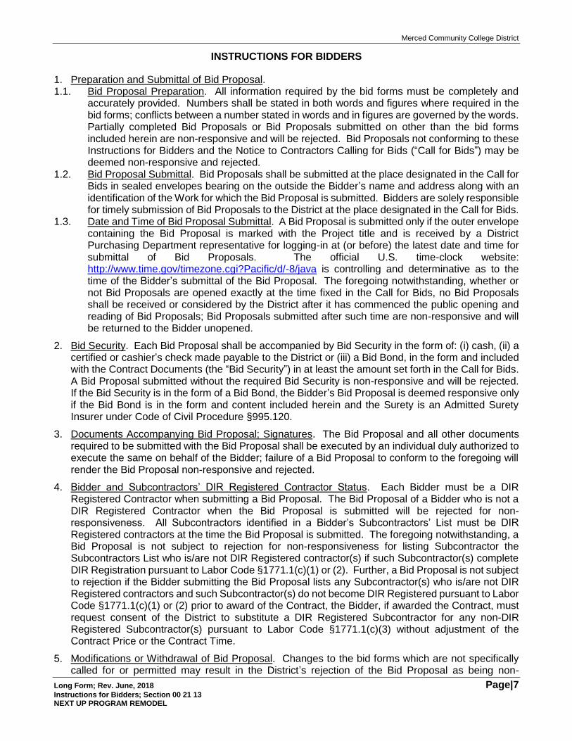
1. Preparation and Submittal of Bid Proposal. 1.1. Bid Proposal Preparation. All information required by the bid forms must be completely and
accurately provided. Numbers shall be stated in both words and figures where required in the bid forms; conflicts between a number stated in words and in figures are governed by the words. Partially completed Bid Proposals or Bid Proposals submitted on other than the bid forms included herein are non-responsive and will be rejected. Bid Proposals not conforming to these Instructions for Bidders and the Notice to Contractors Calling for Bids (“Call for Bids”) may be deemed non-responsive and rejected.
1.2. Bid Proposal Submittal. Bid Proposals shall be submitted at the place designated in the Call for Bids in sealed envelopes bearing on the outside the Bidder’s name and address along with an identification of the Work for which the Bid Proposal is submitted. Bidders are solely responsible for timely submission of Bid Proposals to the District at the place designated in the Call for Bids.
1.3. Date and Time of Bid Proposal Submittal. A Bid Proposal is submitted only if the outer envelope containing the Bid Proposal is marked with the Project title and is received by a District Purchasing Department representative for logging-in at (or before) the latest date and time for submittal of Bid Proposals. The official U.S. time-clock website: http://www.time.gov/timezone.cgi?Pacific/d/-8/java is controlling and determinative as to the time of the Bidder’s submittal of the Bid Proposal. The foregoing notwithstanding, whether or not Bid Proposals are opened exactly at the time fixed in the Call for Bids, no Bid Proposals shall be received or considered by the District after it has commenced the public opening and reading of Bid Proposals; Bid Proposals submitted after such time are non-responsive and will be returned to the Bidder unopened.
2. Bid Security. Each Bid Proposal shall be accompanied by Bid Security in the form of: (i) cash, (ii) a certified or cashier’s check made payable to the District or (iii) a Bid Bond, in the form and included with the Contract Documents (the “Bid Security”) in at least the amount set forth in the Call for Bids. A Bid Proposal submitted without the required Bid Security is non-responsive and will be rejected. If the Bid Security is in the form of a Bid Bond, the Bidder’s Bid Proposal is deemed responsive only if the Bid Bond is in the form and content included herein and the Surety is an Admitted Surety Insurer under Code of Civil Procedure §995.120.
3. Documents Accompanying Bid Proposal; Signatures. The Bid Proposal and all other documents required to be submitted with the Bid Proposal shall be executed by an individual duly authorized to execute the same on behalf of the Bidder; failure of a Bid Proposal to conform to the foregoing will render the Bid Proposal non-responsive and rejected.
4. Bidder and Subcontractors’ DIR Registered Contractor Status. Each Bidder must be a DIR Registered Contractor when submitting a Bid Proposal. The Bid Proposal of a Bidder who is not a DIR Registered Contractor when the Bid Proposal is submitted will be rejected for non-responsiveness. All Subcontractors identified in a Bidder’s Subcontractors’ List must be DIR Registered contractors at the time the Bid Proposal is submitted. The foregoing notwithstanding, a Bid Proposal is not subject to rejection for non-responsiveness for listing Subcontractor the Subcontractors List who is/are not DIR Registered contractor(s) if such Subcontractor(s) complete DIR Registration pursuant to Labor Code §1771.1(c)(1) or (2). Further, a Bid Proposal is not subject to rejection if the Bidder submitting the Bid Proposal lists any Subcontractor(s) who is/are not DIR Registered contractors and such Subcontractor(s) do not become DIR Registered pursuant to Labor Code §1771.1(c)(1) or (2) prior to award of the Contract, the Bidder, if awarded the Contract, must request consent of the District to substitute a DIR Registered Subcontractor for any non-DIR Registered Subcontractor(s) pursuant to Labor Code §1771.1(c)(3) without adjustment of the Contract Price or the Contract Time.
5. Modifications or Withdrawal of Bid Proposal. Changes to the bid forms which are not specifically called for or permitted may result in the District’s rejection of the Bid Proposal as being non-
Merced Community College District
Long Form; Rev. June, 2018 Page|8 Instructions for Bidders; Section 00 21 13 NEXT UP PROGRAM REMODEL
responsive. No oral or telephonic modification of any submitted Bid Proposal will be considered. After submittal of a Bid Proposal, a Bidder may modify or withdraw its Bid Proposal only by written request actually received by the District prior to the scheduled closing time for the receipt of Bid Proposals and the District’s public opening and reading of Bid Proposals; written requests to withdraw or modify a submitted Bid Proposal received by the District after the scheduled closing time for receipt of Bid Proposals shall not be considered by the District, nor effective to withdraw such Bid Proposal.
6. Erasures; Inconsistent or Illegible Bid Proposals. Erasures, interlineations or other corrections to any document submitted with a Bid Proposal shall be suitably authenticated by affixing in the margin immediately opposite such erasure, interlineations or correction the surname(s) of the person(s) signing the Bid Proposal. Any Bid Proposal not conforming to the foregoing may be deemed by the District to be non-responsive. If any Bid Proposal or portions thereof, is determined by the District to be illegible, ambiguous or inconsistent, the District may reject such a Bid Proposal as being non-responsive.
7. Examination of Site and Contract Documents. Each Bidder shall, at its sole cost and expense, inspect the Site and to become fully acquainted with the Contract Documents and conditions affecting the Work. Failure of a Bidder to receive or examine any of the Contract Documents or to inspect the Site shall not relieve such Bidder from any obligation with respect to the Bid Proposal, or the Work required under the Contract Documents. The District assumes no responsibility or liability to any Bidder for, nor shall the District be bound by, any understandings, representations or agreements of the District’s agents, employees or officers concerning the Contract Documents or the Work made prior to execution of the Contract which are not in the form of Bid Addenda duly issued by the District. The submission of a Bid Proposal shall be deemed prima facie evidence of the Bidder’s full compliance with the requirements of this section.
8. Agreement and Bonds. The Agreement which the successful Bidder, as Contractor, will be required to execute along with the forms Payment Bond, Performance Bond and other documents and instruments which are required to be furnished are included in the Contract Documents and shall be carefully examined by the Bidder.
9. Interpretation of Drawings, Specifications or Contract Documents. The District will respond to any pre-bid inquiry submitted in accordance with requirements established in the Call for Bids. If in the sole discretion of the District, a response to a pre-bid inquiry affects or potentially affects other Bidders, the Work, the Contract Documents or other requirements, the District will issue addenda. A copy of any such addendum will be delivered by fax, email or mail to each Bidder receiving a set of the Contract Documents. No person is authorized to render an oral interpretation or correction of any portion of the Contract Documents to any Bidder, and no Bidder is authorized to rely on any such oral interpretation or correction. Failure to request interpretation or clarification of any portion of the Contract Documents pursuant to the foregoing is a waiver of any discrepancy, defect or conflict therein.
10. District’s Right to Modify Contract Documents. Before the public opening and reading of Bid Proposals, the District may modify the Work, the Contract Documents, or any portion(s) thereof by the issuance of written addenda disseminated to all Bidders who have obtained a copy of the Specifications, Drawings and Contract Documents pursuant to the Call for Bids. If the District issues any addenda during the bidding, the failure of any Bidder to acknowledge such addenda in its Bid Proposal will render the Bid Proposal non-responsive and rejected.
11. Bidders Interested in More Than One Bid Proposal; Non-Collusion Affidavit. No person, firm, corporation or other entity shall submit or be interested in more than one Bid Proposal for the same Work; provided, however, that a person, firm or corporation that has submitted a sub-proposal to a Bidder or who has quoted prices for materials to a Bidder is not disqualified from submitting a sub-proposal, quoting prices to other Bidders or submitting a Bid Proposal for the proposed Work to the District. The form of Non-Collusion Affidavit included in the Contract Documents must be completed
Merced Community College District
Long Form; Rev. June, 2018 Page|9 Instructions for Bidders; Section 00 21 13 NEXT UP PROGRAM REMODEL
and duly executed on behalf of the Bidder; failure of a Bidder to submit a completed and executed Non-Collusion Affidavit with its Bid Proposal will render the Bid Proposal non-responsive.
12. Award of Contract. 12.1. Waiver of Irregularities or Informalities. The District reserves the right to reject any and
all Bid Proposals or to waive any irregularities or informalities in any Bid Proposal or in the bidding.
12.2. Award to Lowest Responsive Responsible Bidder. The award of the Contract, if made by the District through action of its Board of Trustees, will be to the responsible Bidder submitting the lowest responsive Bid Proposal on the basis of the Base Bid Proposal and Alternate Bid Items selected in accordance with these Instructions.
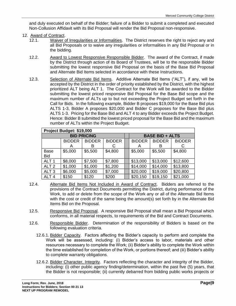
12.3. Selection of Alternate Bid Items. Additive Alternate Bid Items (“ALT”), if any, will be accepted by the District in the order of priority established by the District, with the highest prioritized ALT being ALT 1. The Contract for the Work will be awarded to the Bidder submitting the lowest priced responsive Bid Proposal for the Base Bid scope and the maximum number of ALTs up to but not exceeding the Project Budget set forth in the Call for Bids. In the following example, Bidder B proposes $19,000 for the Base Bid plus ALTS 1-3, Bidder A proposes $20,000 and Bidder C proposes for the Base Bid plus ALTS 1-3. Pricing for the Base Bid and ALT 4 to any Bidder exceeds the Project Budget. Hence: Bidder B submitted the lowest priced proposal for the Base Bid and the maximum number of ALTs within the Project Budget.
Project Budget: $19,000
BID PRICING BASE BID + ALTS
BIDDER A
BIDDER B
BIDDER C
BIDDER A
BIDDER B
BIDDER C
Base Bid
$5,000 $5,500 $4,800 $5,000 $5,500 $4,800
ALT 1 $8,000 $7,500 $7,800 $13,000 $13,000 $12,600
ALT 2 $1,000 $1,000 $1,200 $14,000 $14,000 $13,800
ALT 3 $6,000 $5,000 $7,000 $20,000 $19,000 $20,800
ALT 4 $150 $120 $200 $20,150 $19,150 $21,000
12.4. Alternate Bid Items Not Included in Award of Contract. Bidders are referred to the provisions of the Contract Documents permitting the District, during performance of the Work, to add or delete from the scope of the Work any or all of the Alternate Bid Items with the cost or credit of the same being the amount(s) set forth by in the Alternate Bid Items Bid on the Proposal.
12.5. Responsive Bid Proposal. A responsive Bid Proposal shall mean a Bid Proposal which conforms, in all material respects, to requirements of the Bid and Contract Documents.
12.6. Responsible Bidder. Determination of the responsibility of Bidders is based on the following evaluation criteria.
12.6.1. Bidder Capacity. Factors affecting the Bidder’s capacity to perform and complete the Work will be assessed, including: (i) Bidder’s access to labor, materials and other resources necessary to complete the Work; (ii) Bidder’s ability to complete the Work within the time established for completion of the Work, or portions thereof; and (iii) Bidder’s ability to complete warranty obligations.
12.6.2. Bidder Character, Integrity. Factors reflecting the character and integrity of the Bidder, including: (i) other public agency finding/determination, within the past five (5) years, that the Bidder is not responsible; (ii) currently debarred from bidding public works projects or
Merced Community College District
Long Form; Rev. June, 2018 Page|10 Instructions for Bidders; Section 00 21 13 NEXT UP PROGRAM REMODEL
debarment from bidding within past five (5) years; and (iii) false claims liability within the past five (5) years under local, state or federal laws.
12.6.3. Bidder Financial Capability. Factors considered include: (i) sufficiency of the Bidder’s financial resources; (ii) whether the Bidder is current in payment of debts and performance of other financial obligations; and (iii) bankruptcy or insolvency proceedings have been instituted within the past five (5) years.
12.6.4. Bidder Prior Performance. The Bidder’s prior performance on prior public works contracts, including without limitation: (i) cost overruns; (ii) compliance with general conditions and other contractual requirements, including schedule development, schedule updates and coordination of labor, material/equipment procurements and subcontractors; (iii) completion within allocated time; (iv) submittal of unsubstantiated, unsupported or excessive cost proposals, claims or contract adjustment requests; (iv) completion of a project by a surety; (vi) owner’s exercise of default remedies; and (vii) finding or determination by any public agency that the Bidder is not a responsible bidder.
12.6.5. Safety. Factors include: (i) findings of serious or willful safety violations of safety laws, regulations or requirements by any local, state or federal agency within the past five (5) years; (ii) adequacy and implementation of safety plans, programs for on-site and off-site construction and construction related activities; and (iii) Workers Compensation Insurance EMR rating exceeding 1.25.
13. Subcontractors. 13.1. Designation of Subcontractors; Subcontractors List. Each Bidder shall submit a list of
its proposed Subcontractors for the proposed Work as required by the Subletting and Subcontracting Fair Practices Act (California Public Contract Code §§ 4100 et seq.) on the form furnished. The failure of any Bid Proposal to include all information required by the Subcontractors List will result in rejection of the Bid Proposal for non-responsiveness.
13.2. Work of Subcontractors. All Bidders are referred to the Contract Documents and the notation therein that all Contract Documents are intended to be complimentary and that the organization or arrangements of the Specifications and Drawings shall not limit the extent of the Work of the Contract Documents. Accordingly, all Bidders are encouraged to disseminate all of the Specifications, Drawings and other Contract Documents to all persons or entities submitting sub-bids to the Bidder. The omission of any portion or item of Work from the Bid Proposal or from the sub-bidders’ sub-bids which is/are necessary to produce the intended results and/or which are reasonably inerrable from the Contract Documents is not a basis for adjustment of the Contract Price or the Contract Time.
14.4. Subcontractor Bonds. In accordance with California Public Contract Code §4108, if a Bidder requires a bond or bonds of its Subcontractor(s), whether the expense of procuring such bond or bonds are to be borne by the Bidder or the Subcontractor(s), such requirements shall be specified in the Bidder’s written or published request for sub-bids. Failure of the Bidder to comply with these requirements shall preclude the Bidder from imposing bonding requirements upon its Subcontractor(s) or rejection of a Subcontractor’s bid under California Public Contract Code §4108(b).
13 Workers’ Compensation Insurance. Pursuant to California Labor Code § 3700, the successful Bidder shall secure Workers’ Compensation Insurance for its employees engaged in the Work of the Contract. The successful Bidder shall execute and deliver to the District the form of Workers Compensation Certification included in the Contract Documents concurrently with such Bidder’s delivery of the executed Agreement to the District.
15. Bid Security Return. The Bid Security of the Bidders submitting the three lowest priced Bid Proposals, the number being solely at the discretion of the District, will be held by the District for ten
Merced Community College District
Long Form; Rev. June, 2018 Page|11 Instructions for Bidders; Section 00 21 13 NEXT UP PROGRAM REMODEL
(10) days after the period for which Bid Proposals must be held open (which is set forth in the Call for Bids) or until posting by the successful Bidder(s) of the bonds, certificates of insurance required and return of executed copies of the Agreement, whichever first occurs, at which time the Bid Security of such other Bidders will be returned to them.
16. Contractor’s License. No Bid Proposal will be considered from a Bidder who, at the time Bid Proposals are opened, is not licensed to perform the Work of the Contract Documents, in accordance with the Contractors’ License Law, California Business & Professions Code §§7000 et seq. This requirement is not a mere formality and will not be waived by the District or its Board of Trustees. The required California Contractors’ License classification(s) for the Work is set forth in the Call for Bids.
17. Non-Discriminatory Practices. It is the policy of the District that there be no discrimination against any prospective or active employee engaged in the Work because of race, color, ancestry, national origin, religious creed, sex, age, marital status or other legally protected classification. All Bidders agree to comply with the District’s non-discrimination policy and all applicable Federal and California anti-discrimination laws including but not limited to the California Fair Employment & Housing Act beginning with California Government Code §§ 12940 et seq. and California Labor Code § 1735. In addition, all Bidders agree to require like compliance by any Subcontractor employed by them on the Work of the Contract.
18. Bidder’s Qualifications. Each Bidder shall submit with its Bid Proposal the form of Statement of Bidder’s Qualifications, which is included within the Contract Documents. All information required by Statement of Bidder’s Qualifications shall be completely and fully provided. Any Bid Proposal not accompanied by the Statement of Bidder’s Qualifications completed with all information required and bearing the signature of the Bidder’s duly authorized representative under penalty of perjury will render the Bid Proposal non-responsive and rejected. If the District determines that any information provided by a Bidder in the Statement of Bidder’s Qualifications is false or misleading, or is incomplete so as to be false or misleading, the District may reject the Bid Proposal submitted by such Bidder as being non-responsive.
19. Job-Walk. The District will conduct a Job-Walk at the time(s) and place(s) designated in the Call for Bids. The District may, in its sole and exclusive discretion, elect to conduct one or more Job-Walk(s) in addition to that set forth in the Call for Bids, in which event the District shall notify all Bidders who have theretofore obtained the Contract Documents pursuant to the Call for Bids of any such additional Job-Walk. If the District elects to conduct any Job-Walk in addition to that set forth in the Call for Bids, the District shall, in its notice of any such additional Job-Walk(s), indicate whether Bidders’ attendance at such additional Job-Walk(s) is/are mandatory. If attendance at the Job Walk is indicated in the Call for Bids as being mandatory, the failure of any Bidder to have its authorized representative present at the entirety of the Job-Walk will render the Bid Proposal of such Bidder to be non-responsive. Where the Job-Walk is mandatory, a Bidder may have more than one authorized representative and/or representatives of its Subcontractors present at the Job-Walk; provided, however that attendance by representatives of the Bidder’s Subcontractors without attendance by a representative of the Bidder shall not be sufficient to meet the Bidder’s obligations hereunder and will render the Bid Proposal of such Bidder to be non-responsive. The District will reject the Bid Proposal of a Bidder who obtains the Bid and Contract Documents after the date of the Mandatory Job-Walks set forth in the Call for Bids unless a Job-Walk is requested by such Bidder and a Job-Walk is conducted by the District in accordance with the following provisions. The District may, in its sole and exclusive discretion, conduct such requested Job-Walk taking into consideration factors such as the time remaining prior to the scheduled opening of Bid Proposals. Any such requested Job Walk will be conducted only upon the requesting Bidder’s agreement to reimburse the District for the actual and/or reasonable costs for the District’s staff and its agents and representatives in arranging for and conducting such additional Job-Walk.
Merced Community College District
Long Form; Rev. June, 2018 Page|12 Instructions for Bidders; Section 00 21 13 NEXT UP PROGRAM REMODEL
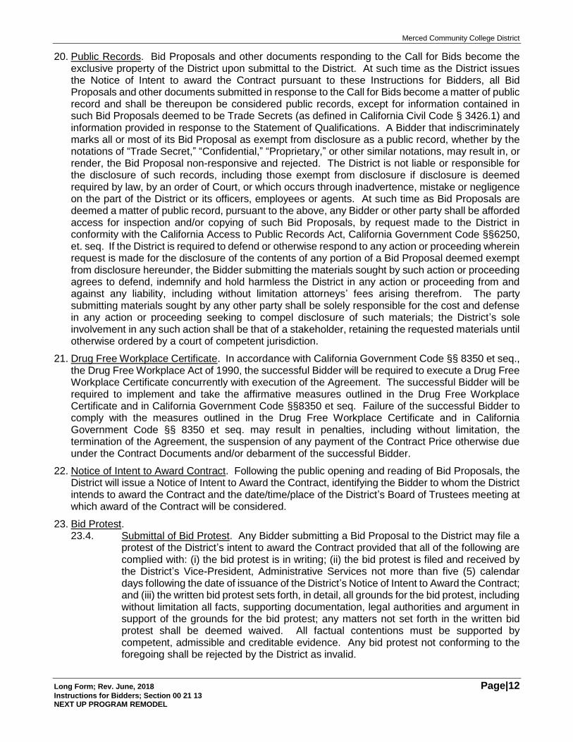
20. Public Records. Bid Proposals and other documents responding to the Call for Bids become the exclusive property of the District upon submittal to the District. At such time as the District issues the Notice of Intent to award the Contract pursuant to these Instructions for Bidders, all Bid Proposals and other documents submitted in response to the Call for Bids become a matter of public record and shall be thereupon be considered public records, except for information contained in such Bid Proposals deemed to be Trade Secrets (as defined in California Civil Code § 3426.1) and information provided in response to the Statement of Qualifications. A Bidder that indiscriminately marks all or most of its Bid Proposal as exempt from disclosure as a public record, whether by the notations of “Trade Secret,” “Confidential,” “Proprietary,” or other similar notations, may result in, or render, the Bid Proposal non-responsive and rejected. The District is not liable or responsible for the disclosure of such records, including those exempt from disclosure if disclosure is deemed required by law, by an order of Court, or which occurs through inadvertence, mistake or negligence on the part of the District or its officers, employees or agents. At such time as Bid Proposals are deemed a matter of public record, pursuant to the above, any Bidder or other party shall be afforded access for inspection and/or copying of such Bid Proposals, by request made to the District in conformity with the California Access to Public Records Act, California Government Code §§6250, et. seq. If the District is required to defend or otherwise respond to any action or proceeding wherein request is made for the disclosure of the contents of any portion of a Bid Proposal deemed exempt from disclosure hereunder, the Bidder submitting the materials sought by such action or proceeding agrees to defend, indemnify and hold harmless the District in any action or proceeding from and against any liability, including without limitation attorneys’ fees arising therefrom. The party submitting materials sought by any other party shall be solely responsible for the cost and defense in any action or proceeding seeking to compel disclosure of such materials; the District’s sole involvement in any such action shall be that of a stakeholder, retaining the requested materials until otherwise ordered by a court of competent jurisdiction.
21. Drug Free Workplace Certificate. In accordance with California Government Code §§ 8350 et seq., the Drug Free Workplace Act of 1990, the successful Bidder will be required to execute a Drug Free Workplace Certificate concurrently with execution of the Agreement. The successful Bidder will be required to implement and take the affirmative measures outlined in the Drug Free Workplace Certificate and in California Government Code §§8350 et seq. Failure of the successful Bidder to comply with the measures outlined in the Drug Free Workplace Certificate and in California Government Code §§ 8350 et seq. may result in penalties, including without limitation, the termination of the Agreement, the suspension of any payment of the Contract Price otherwise due under the Contract Documents and/or debarment of the successful Bidder.
22. Notice of Intent to Award Contract. Following the public opening and reading of Bid Proposals, the District will issue a Notice of Intent to Award the Contract, identifying the Bidder to whom the District intends to award the Contract and the date/time/place of the District’s Board of Trustees meeting at which award of the Contract will be considered.
23. Bid Protest. 23.4. Submittal of Bid Protest. Any Bidder submitting a Bid Proposal to the District may file a
protest of the District’s intent to award the Contract provided that all of the following are complied with: (i) the bid protest is in writing; (ii) the bid protest is filed and received by the District’s Vice-President, Administrative Services not more than five (5) calendar days following the date of issuance of the District’s Notice of Intent to Award the Contract; and (iii) the written bid protest sets forth, in detail, all grounds for the bid protest, including without limitation all facts, supporting documentation, legal authorities and argument in support of the grounds for the bid protest; any matters not set forth in the written bid protest shall be deemed waived. All factual contentions must be supported by competent, admissible and creditable evidence. Any bid protest not conforming to the foregoing shall be rejected by the District as invalid.
Merced Community College District
Long Form; Rev. June, 2018 Page|13 Instructions for Bidders; Section 00 21 13 NEXT UP PROGRAM REMODEL
23.5. District Review and Disposition of Bid Protest. Provided that a bid protest is filed in strict conformity with the foregoing, the District’s Vice-President, Administrative Services or such individual(s) as may be designated by him/her (Designee), shall review and evaluate the basis of the bid protest. The District’s Vice-President, Administrative Services or Designee shall provide the Bidder submitting the bid protest with a written statement concurring with or denying the bid protest (Bid Protest Response). The Bid Protest Response is deemed the final action of the District and not subject to appeal or reconsideration by any other employee or officer of the District or the Board of Trustees of the District. The issuance of the Bid Protest Response by the District’s Vice-President, Administrative Services or the Designee is an express condition precedent to the institution of any legal or equitable proceedings relative to the bidding process, the District’s intent to award the Contract, the District’s disposition of any bid protest or the District’s decision to reject all Bid Proposals. If any such legal or equitable proceedings are instituted and the District is named as a party thereto, the prevailing party(ies) shall recover from the other party(ies), as costs, all attorneys’ fees and costs incurred in connection with any such proceeding, including any appeal arising therefrom.
[End of Section]
Merced Community College District
Long Form; Rev. June, 2018 Page|14 NEXT UP PROGRAM REMODEL
[THIS PAGE INTENTIONALLY BLANK]
Merced Community College District
Long Form; Rev. June, 2018 Page|15 Bid Proposal; Section 00 41 22 NEXT UP PROGRAM REMODEL
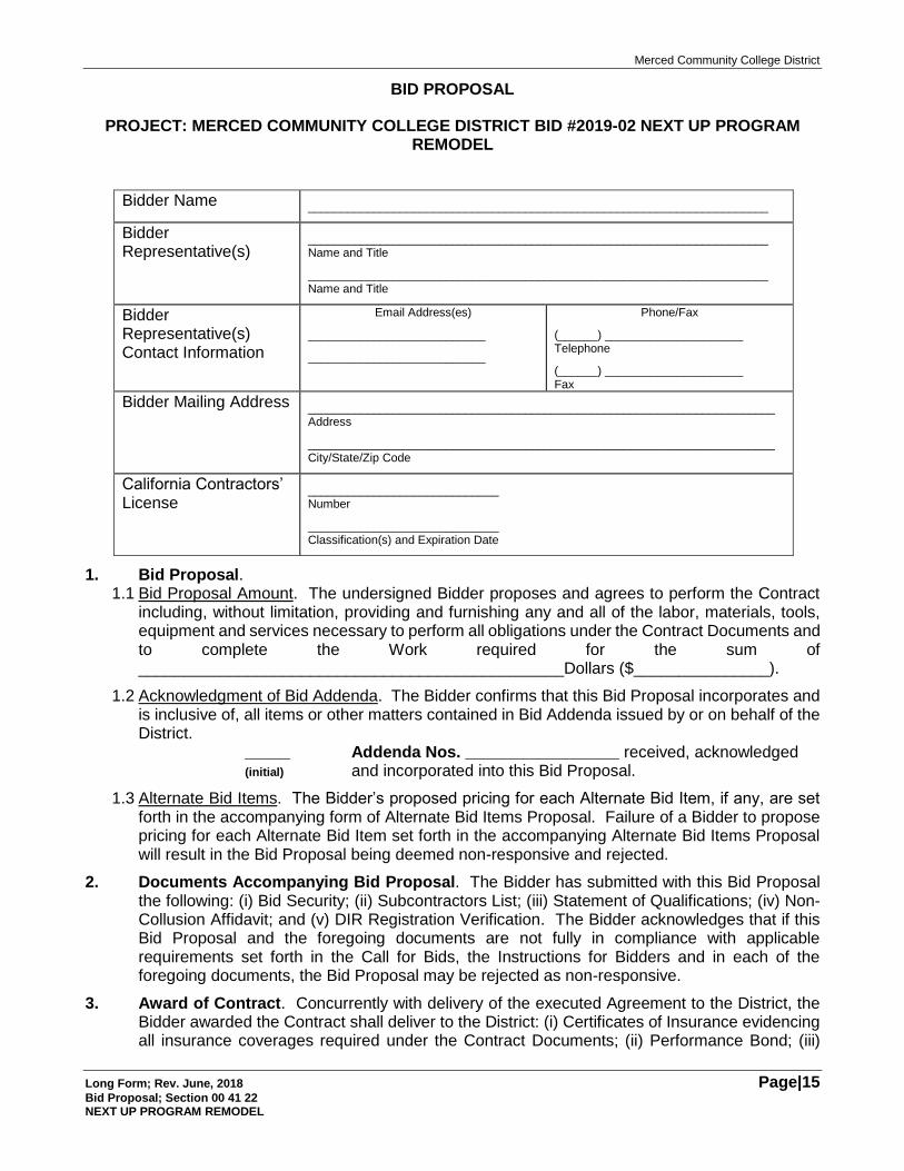
BID PROPOSAL
PROJECT: MERCED COMMUNITY COLLEGE DISTRICT BID #2019-02 NEXT UP PROGRAM REMODEL
Bidder Name ______________________________________________________________________
Bidder Representative(s)
______________________________________________________________________ Name and Title
______________________________________________________________________ Name and Title
Bidder Representative(s) Contact Information
Email Address(es)
___________________________
___________________________
Phone/Fax
(______) _____________________ Telephone
(______) _____________________ Fax
Bidder Mailing Address _______________________________________________________________________ Address
_______________________________________________________________________ City/State/Zip Code
California Contractors’ License
_____________________________ Number
_____________________________ Classification(s) and Expiration Date
1. Bid Proposal. 1.1 Bid Proposal Amount. The undersigned Bidder proposes and agrees to perform the Contract
including, without limitation, providing and furnishing any and all of the labor, materials, tools, equipment and services necessary to perform all obligations under the Contract Documents and to complete the Work required for the sum of _______________________________________________Dollars ($_______________).
1.2 Acknowledgment of Bid Addenda. The Bidder confirms that this Bid Proposal incorporates and is inclusive of, all items or other matters contained in Bid Addenda issued by or on behalf of the District.
_____ Addenda Nos. _________________ received, acknowledged (initial) and incorporated into this Bid Proposal.
1.3 Alternate Bid Items. The Bidder’s proposed pricing for each Alternate Bid Item, if any, are set forth in the accompanying form of Alternate Bid Items Proposal. Failure of a Bidder to propose pricing for each Alternate Bid Item set forth in the accompanying Alternate Bid Items Proposal will result in the Bid Proposal being deemed non-responsive and rejected.
2. Documents Accompanying Bid Proposal. The Bidder has submitted with this Bid Proposal the following: (i) Bid Security; (ii) Subcontractors List; (iii) Statement of Qualifications; (iv) Non-Collusion Affidavit; and (v) DIR Registration Verification. The Bidder acknowledges that if this Bid Proposal and the foregoing documents are not fully in compliance with applicable requirements set forth in the Call for Bids, the Instructions for Bidders and in each of the foregoing documents, the Bid Proposal may be rejected as non-responsive.
3. Award of Contract. Concurrently with delivery of the executed Agreement to the District, the Bidder awarded the Contract shall deliver to the District: (i) Certificates of Insurance evidencing all insurance coverages required under the Contract Documents; (ii) Performance Bond; (iii)
Merced Community College District
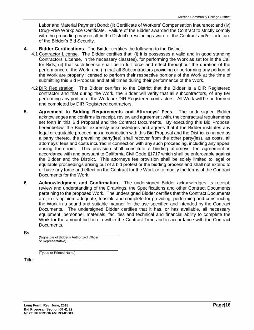
Long Form; Rev. June, 2018 Page|16 Bid Proposal; Section 00 41 22 NEXT UP PROGRAM REMODEL
Labor and Material Payment Bond; (ii) Certificate of Workers’ Compensation Insurance; and (iv) Drug-Free Workplace Certificate. Failure of the Bidder awarded the Contract to strictly comply with the preceding may result in the District’s rescinding award of the Contract and/or forfeiture of the Bidder’s Bid Security.
4. Bidder Certifications. The Bidder certifies the following to the District: 4.1 Contractor License. The Bidder certifies that: (i) it is possesses a valid and in good standing
Contractors’ License, in the necessary class(es), for performing the Work as set for in the Call for Bids; (ii) that such license shall be in full force and effect throughout the duration of the performance of the Work; and (ii) that all Subcontractors providing or performing any portion of the Work are properly licensed to perform their respective portions of the Work at the time of submitting this Bid Proposal and at all times during their performance of the Work.
4.2 DIR Registration. The Bidder certifies to the District that the Bidder is a DIR Registered contractor and that during the Work, the Bidder will verify that all subcontractors, of any tier performing any portion of the Work are DIR Registered contractors. All Work will be performed and completed by DIR Registered contractors.
5. Agreement to Bidding Requirements and Attorneys’ Fees. The undersigned Bidder acknowledges and confirms its receipt, review and agreement with, the contractual requirements set forth in this Bid Proposal and the Contract Documents. By executing this Bid Proposal hereinbelow, the Bidder expressly acknowledges and agrees that if the Bidder institutes any legal or equitable proceedings in connection with this Bid Proposal and the District is named as a party thereto, the prevailing party(ies) shall recover from the other party(ies), as costs, all attorneys’ fees and costs incurred in connection with any such proceeding, including any appeal arising therefrom. This provision shall constitute a binding attorneys’ fee agreement in accordance with and pursuant to California Civil Code §1717 which shall be enforceable against the Bidder and the District. This attorneys fee provision shall be solely limited to legal or equitable proceedings arising out of a bid protest or the bidding process and shall not extend to or have any force and effect on the Contract for the Work or to modify the terms of the Contract Documents for the Work.
6. Acknowledgment and Confirmation. The undersigned Bidder acknowledges its receipt, review and understanding of the Drawings, the Specifications and other Contract Documents pertaining to the proposed Work. The undersigned Bidder certifies that the Contract Documents are, in its opinion, adequate, feasible and complete for providing, performing and constructing the Work in a sound and suitable manner for the use specified and intended by the Contract Documents. The undersigned Bidder certifies that it has, or has available, all necessary equipment, personnel, materials, facilities and technical and financial ability to complete the Work for the amount bid herein within the Contract Time and in accordance with the Contract Documents.
By: _______________________________ (Signature of Bidder’s Authorized Officer or Representative)
_______________________________ (Typed or Printed Name)
Title: ______________________________
Merced Community College District
Long Form; Rev. June, 2018 Page|17 Bid Proposal -Alternate Bid Items; Section 00 42 13 NEXT UP PROGRAM REMODEL
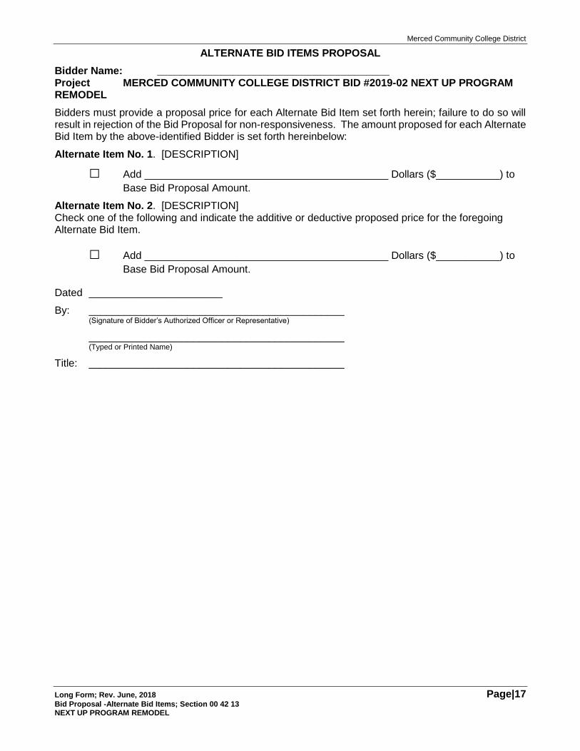
ALTERNATE BID ITEMS PROPOSAL
Bidder Name: ________________________________________ Project MERCED COMMUNITY COLLEGE DISTRICT BID #2019-02 NEXT UP PROGRAM REMODEL
Bidders must provide a proposal price for each Alternate Bid Item set forth herein; failure to do so will result in rejection of the Bid Proposal for non-responsiveness. The amount proposed for each Alternate Bid Item by the above-identified Bidder is set forth hereinbelow:
Alternate Item No. 1. [DESCRIPTION]
□ Add __________________________________________ Dollars ($___________) to
Base Bid Proposal Amount.
Alternate Item No. 2. [DESCRIPTION] Check one of the following and indicate the additive or deductive proposed price for the foregoing Alternate Bid Item.
□ Add __________________________________________ Dollars ($___________) to
Base Bid Proposal Amount.
Dated _______________________
By: ____________________________________________ (Signature of Bidder’s Authorized Officer or Representative)
____________________________________________ (Typed or Printed Name)
Title: ____________________________________________

Merced Community College District
Long Form; Rev. June, 2018 Page|18 NEXT UP PROGRAM REMODEL
THIS PAGE INTENTIONALLY BLANK
Merced Community College District
Long Form; Rev. June, 2018 Page|19 Subcontractor’s List; Section 00 43 36 NEXT UP PROGRAM REMODEL
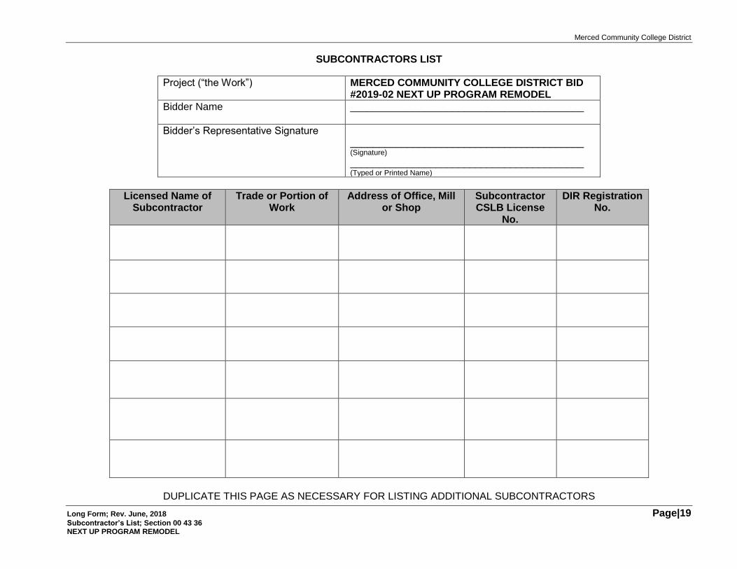
SUBCONTRACTORS LIST
Project (“the Work”) MERCED COMMUNITY COLLEGE DISTRICT BID #2019-02 NEXT UP PROGRAM REMODEL
Bidder Name _________________________________________
Bidder’s Representative Signature _________________________________________ (Signature)
_________________________________________ (Typed or Printed Name)
Licensed Name of Subcontractor
Trade or Portion of Work
Address of Office, Mill or Shop
Subcontractor CSLB License
No.
DIR Registration No.
DUPLICATE THIS PAGE AS NECESSARY FOR LISTING ADDITIONAL SUBCONTRACTORS
Merced Community College District
Long Form; Rev. June, 2018 Page|20 NEXT UP PROGRAM REMODEL
THIS PAGE INTENTIONALLY BLANK
Merced Community College District
Long Form; Rev. June, 2018 Page|21 DIR Registration Verification; Section 00 45 10 NEXT UP PROGRAM REMODEL
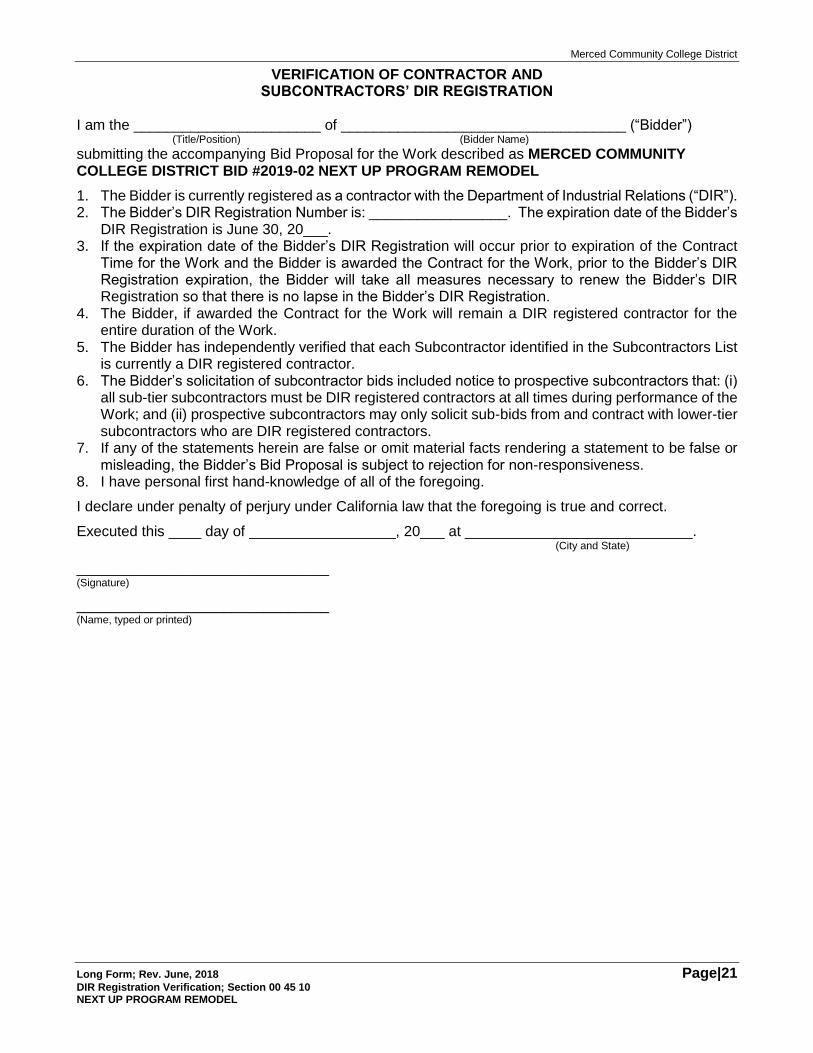
VERIFICATION OF CONTRACTOR AND SUBCONTRACTORS’ DIR REGISTRATION
I am the _______________________ of ___________________________________ (“Bidder”)
(Title/Position) (Bidder Name)
submitting the accompanying Bid Proposal for the Work described as MERCED COMMUNITY COLLEGE DISTRICT BID #2019-02 NEXT UP PROGRAM REMODEL
1. The Bidder is currently registered as a contractor with the Department of Industrial Relations (“DIR”). 2. The Bidder’s DIR Registration Number is: _________________. The expiration date of the Bidder’s
DIR Registration is June 30, 20___. 3. If the expiration date of the Bidder’s DIR Registration will occur prior to expiration of the Contract
Time for the Work and the Bidder is awarded the Contract for the Work, prior to the Bidder’s DIR Registration expiration, the Bidder will take all measures necessary to renew the Bidder’s DIR Registration so that there is no lapse in the Bidder’s DIR Registration.
4. The Bidder, if awarded the Contract for the Work will remain a DIR registered contractor for the entire duration of the Work.
5. The Bidder has independently verified that each Subcontractor identified in the Subcontractors List is currently a DIR registered contractor.
6. The Bidder’s solicitation of subcontractor bids included notice to prospective subcontractors that: (i) all sub-tier subcontractors must be DIR registered contractors at all times during performance of the Work; and (ii) prospective subcontractors may only solicit sub-bids from and contract with lower-tier subcontractors who are DIR registered contractors.
7. If any of the statements herein are false or omit material facts rendering a statement to be false or misleading, the Bidder’s Bid Proposal is subject to rejection for non-responsiveness.
8. I have personal first hand-knowledge of all of the foregoing.
I declare under penalty of perjury under California law that the foregoing is true and correct.
Executed this ____ day of __________________, 20___ at ____________________________. (City and State)
_______________________________ (Signature)
_______________________________ (Name, typed or printed)
Merced Community College District
Long Form; Rev. June, 2018 Page|22 AAAA
THIS PAGE INTENTIONALLY BLANK
Merced Community College District
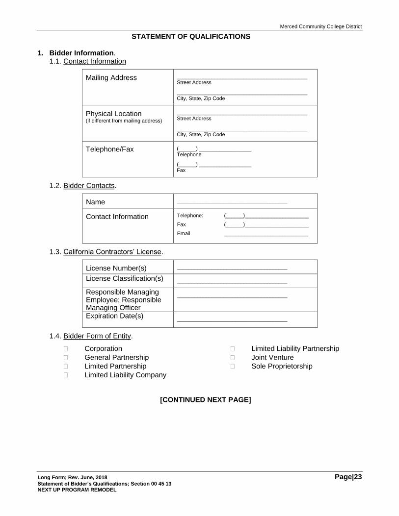
Long Form; Rev. June, 2018 Page|23 Statement of Bidder’s Qualifications; Section 00 45 13 NEXT UP PROGRAM REMODEL
STATEMENT OF QUALIFICATIONS 1. Bidder Information.
1.1. Contact Information
Mailing Address _____________________________________________ Street Address
_____________________________________________ City, State, Zip Code
Physical Location (if different from mailing address)
_____________________________________________ Street Address
_____________________________________________ City, State, Zip Code
Telephone/Fax (______) __________________ Telephone
(______) __________________ Fax
1.2. Bidder Contacts.
Name ______________________________________
Contact Information Telephone: (______)______________________
Fax (______)______________________
Email _____________________________
1.3. California Contractors’ License.
License Number(s) ______________________________________
License Classification(s) ______________________________________
Responsible Managing Employee; Responsible Managing Officer
______________________________________
Expiration Date(s) ______________________________________
1.4. Bidder Form of Entity.
Corporation
General Partnership
Limited Partnership
Limited Liability Company
Limited Liability Partnership
Joint Venture
Sole Proprietorship
[CONTINUED NEXT PAGE]
Merced Community College District
Long Form; Rev. June, 2018 Page|24 Statement of Bidder’s Qualifications; Section 00 45 13 NEXT UP PROGRAM REMODEL
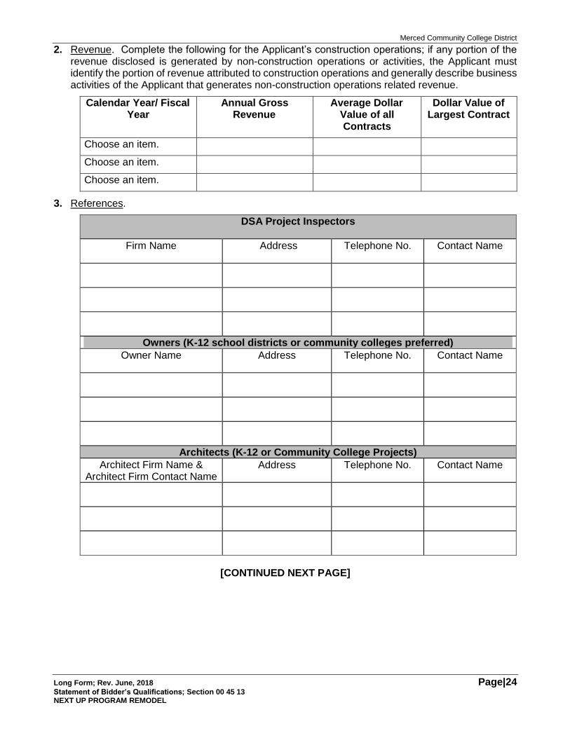
2. Revenue. Complete the following for the Applicant’s construction operations; if any portion of the revenue disclosed is generated by non-construction operations or activities, the Applicant must identify the portion of revenue attributed to construction operations and generally describe business activities of the Applicant that generates non-construction operations related revenue.
Calendar Year/ Fiscal Year
Annual Gross Revenue
Average Dollar Value of all Contracts
Dollar Value of Largest Contract
Choose an item.
Choose an item.
Choose an item.
3. References.
DSA Project Inspectors
Firm Name Address Telephone No. Contact Name
Owners (K-12 school districts or community colleges preferred)
Owner Name Address Telephone No. Contact Name
Architects (K-12 or Community College Projects)
Architect Firm Name & Architect Firm Contact Name
Address Telephone No. Contact Name
[CONTINUED NEXT PAGE]
Merced Community College District
Long Form; Rev. June, 2018 Page|25 Statement of Bidder’s Qualifications; Section 00 45 13 NEXT UP PROGRAM REMODEL
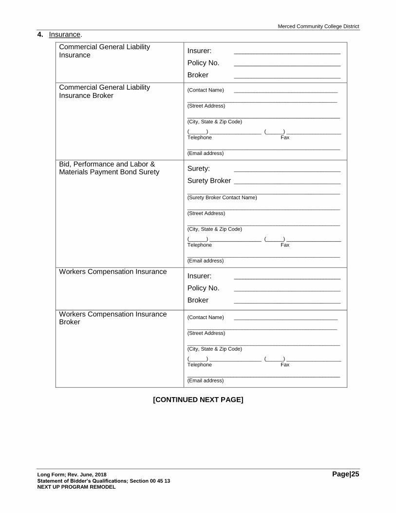
4. Insurance.
Commercial General Liability Insurance
Insurer: _____________________________________
Policy No. _____________________________________
Broker _____________________________________
Commercial General Liability Insurance Broker
(Contact Name) ____________________________________
____________________________________________________ (Street Address)
_____________________________________________________ (City, State & Zip Code)
(______) __________________ (______) ___________________ Telephone Fax
_____________________________________________________ (Email address)
Bid, Performance and Labor & Materials Payment Bond Surety
Surety: _____________________________________
Surety Broker _____________________________________
_____________________________________________________ (Surety Broker Contact Name)
_____________________________________________________ (Street Address)
_____________________________________________________ (City, State & Zip Code)
(______) __________________ (______) ___________________ Telephone Fax
_____________________________________________________ (Email address)
Workers Compensation Insurance Insurer: _____________________________________
Policy No. _____________________________________
Broker _____________________________________
Workers Compensation Insurance Broker
(Contact Name) ____________________________________
____________________________________________________ (Street Address)
_____________________________________________________ (City, State & Zip Code)
(______) __________________ (______) ___________________ Telephone Fax
_____________________________________________________ (Email address)
[CONTINUED NEXT PAGE]
Merced Community College District
Long Form; Rev. June, 2018 Page|26 Statement of Bidder’s Qualifications; Section 00 45 13 NEXT UP PROGRAM REMODEL
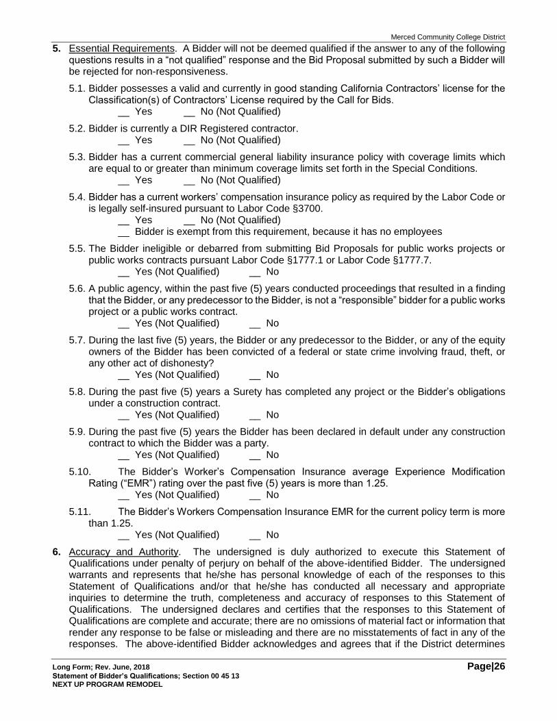
5. Essential Requirements. A Bidder will not be deemed qualified if the answer to any of the following questions results in a “not qualified” response and the Bid Proposal submitted by such a Bidder will be rejected for non-responsiveness.
5.1. Bidder possesses a valid and currently in good standing California Contractors’ license for the Classification(s) of Contractors’ License required by the Call for Bids.
__ Yes __ No (Not Qualified)
5.2. Bidder is currently a DIR Registered contractor. __ Yes __ No (Not Qualified)
5.3. Bidder has a current commercial general liability insurance policy with coverage limits which are equal to or greater than minimum coverage limits set forth in the Special Conditions.
__ Yes __ No (Not Qualified)
5.4. Bidder has a current workers’ compensation insurance policy as required by the Labor Code or is legally self-insured pursuant to Labor Code §3700.
__ Yes __ No (Not Qualified) __ Bidder is exempt from this requirement, because it has no employees
5.5. The Bidder ineligible or debarred from submitting Bid Proposals for public works projects or public works contracts pursuant Labor Code §1777.1 or Labor Code §1777.7.
__ Yes (Not Qualified) __ No
5.6. A public agency, within the past five (5) years conducted proceedings that resulted in a finding that the Bidder, or any predecessor to the Bidder, is not a “responsible” bidder for a public works project or a public works contract.
__ Yes (Not Qualified) __ No
5.7. During the last five (5) years, the Bidder or any predecessor to the Bidder, or any of the equity owners of the Bidder has been convicted of a federal or state crime involving fraud, theft, or any other act of dishonesty?
__ Yes (Not Qualified) __ No
5.8. During the past five (5) years a Surety has completed any project or the Bidder’s obligations under a construction contract.
__ Yes (Not Qualified) __ No
5.9. During the past five (5) years the Bidder has been declared in default under any construction contract to which the Bidder was a party.
__ Yes (Not Qualified) __ No
5.10. The Bidder’s Worker’s Compensation Insurance average Experience Modification Rating (“EMR”) rating over the past five (5) years is more than 1.25.
__ Yes (Not Qualified) __ No
5.11. The Bidder’s Workers Compensation Insurance EMR for the current policy term is more than 1.25.
__ Yes (Not Qualified) __ No
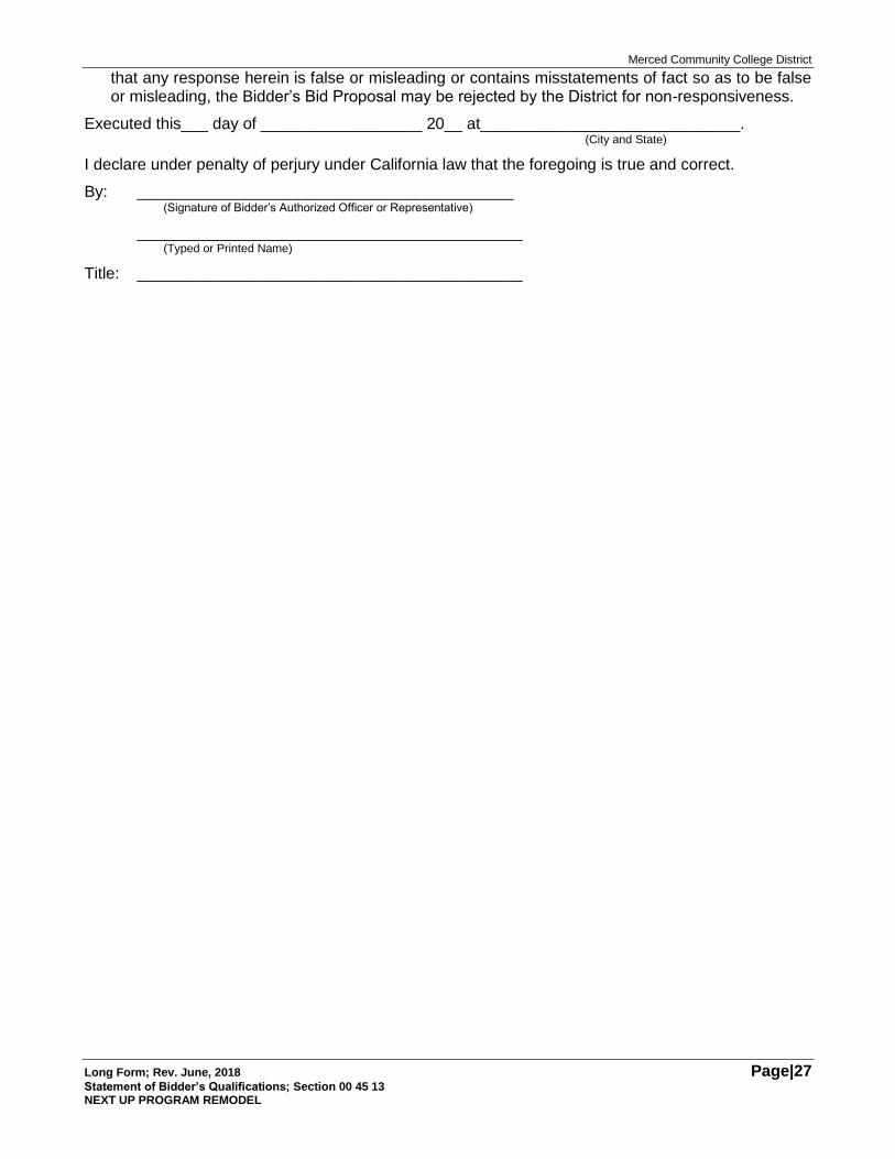
6. Accuracy and Authority. The undersigned is duly authorized to execute this Statement of Qualifications under penalty of perjury on behalf of the above-identified Bidder. The undersigned warrants and represents that he/she has personal knowledge of each of the responses to this Statement of Qualifications and/or that he/she has conducted all necessary and appropriate inquiries to determine the truth, completeness and accuracy of responses to this Statement of Qualifications. The undersigned declares and certifies that the responses to this Statement of Qualifications are complete and accurate; there are no omissions of material fact or information that render any response to be false or misleading and there are no misstatements of fact in any of the responses. The above-identified Bidder acknowledges and agrees that if the District determines
Merced Community College District
Long Form; Rev. June, 2018 Page|27 Statement of Bidder’s Qualifications; Section 00 45 13 NEXT UP PROGRAM REMODEL
that any response herein is false or misleading or contains misstatements of fact so as to be false or misleading, the Bidder’s Bid Proposal may be rejected by the District for non-responsiveness.
Executed this___ day of __________________ 20__ at_____________________________. (City and State)
I declare under penalty of perjury under California law that the foregoing is true and correct.
By: __________________________________________ (Signature of Bidder’s Authorized Officer or Representative)
___________________________________________ (Typed or Printed Name)
Title: ___________________________________________
Merced Community College District
Long Form; Rev. June, 2018 Page|28 Non-Collusion Affidavit; Section 00 45 19
NEXT UP PROGRAM REMODEL
THIS PAGE INTENTIONALLY BLANK
Merced Community College District
Long Form; Rev. June, 2018 Page|29 Non-Collusion Affidavit; Section 00 45 19 NEXT UP PROGRAM REMODEL
NON-COLLUSION AFFIDAVIT
STATE OF CALIFORNIA COUNTY OF ______________________
I, __________________________________, being first duly sworn, deposes and says that I am (Typed or Printed Name)
the ________________________ of ___________________________________, the party submitting (Title) (Bidder Name)
the foregoing Bid Proposal (“the Bidder”). In connection with the foregoing Bid Proposal, the undersigned declares, states and certifies that:
1. The Bid Proposal is not made in the interest of, or on behalf of, any undisclosed person, partnership, company, association, organization or corporation.
2. The Bid Proposal is genuine and not collusive or sham.
3. The Bidder has not directly or indirectly induced or solicited any other bidder to put in a false or sham bid, and has not directly or indirectly colluded, conspired, connived, or agreed with any other bidder or anyone else to put in sham bid, or to refrain from bidding.
4. The Bidder has not in any manner, directly or indirectly, sought by agreement, communication, or conference with anyone to fix the bid price, or that of any other bidder, or to fix any overhead, profit or cost element of the bid price or that of any other bidder, or to secure any advantage against the public body awarding the contract or of anyone interested in the proposed contract.
5. All statements contained in the Bid Proposal and related documents are true.
6. The bidder has not, directly or indirectly, submitted the bid price or any breakdown thereof, or the contents thereof, or divulged information or data relative thereto, or paid, and will not pay, any fee to any person, corporation, partnership, company, association, organization, bid depository, or to any member or agent thereof to effectuate a collusive or sham bid.
Executed this ____ day of ___________, 20__ at _________________________________. (City, County and State)
I declare under penalty of perjury under the laws of the State of California that the foregoing is true and correct.
__________________________________________________ Signature
__________________________________________________ Name Printed or Typed
(________) ________________________________________ (Area Code and Telephone Number)
Merced Community College District
Long Form; Rev. June, 2018 Page|30 NEXT UP PROGRAM REMODEL
[THIS PAGE INTENTIONALLY BLANK]
Merced Community College District
Long Form; Rev. June, 2018 Page|31 Certificate of Workers Compensation Insurance; Section 00 45 23 NEXT UP PROGRAM REMODEL
CERTIFICATE OF WORKERS’ COMPENSATION INSURANCE I,___________________________ the _____________________________________ of
(Name) (Title) ____________________________________, declare, state and certify that:
(Contractor Name)
1. I am aware that California Labor Code § 3700(a) and (b) provides:
“Every employer except the state shall secure the payment of compensation in one or more of the following ways:
(a) By being insured against liability to pay compensation in one or more insurers duly authorized to write compensation insurance in this state. (b) By securing from the Director of Industrial Relations a certificate of consent to self-insure either as an individual employer, or one employer in a group of employers, which may be given upon furnishing proof satisfactory to the Director of Industrial Relations of ability to self-insure and to pay any compensation that may become due to his or her employees.”
2. I am aware that the provisions of California Labor Code §3700 require every employer to be insured against liability for workers’ compensation or to undertake self-insurance in accordance with the provisions of that code, and I will comply with such provisions before commencing the performance of this Contract.
________________________________________ (Contractor Name)
By:______________________________________ (Signature)
_________________________________________ (Typed or printed name)

Merced Community College District
Long Form; Rev. June, 2018 Page|32 NEXT UP PROGRAM REMODEL
THIS PAGE INTENTIONALLY BLANK
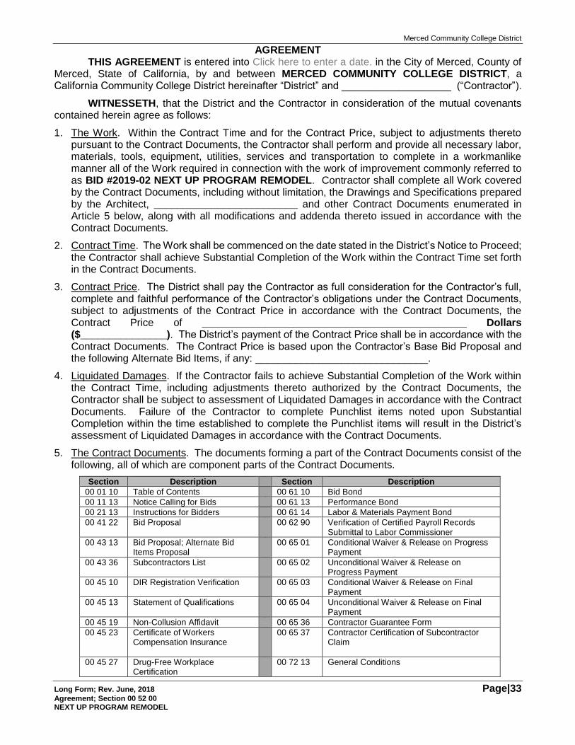
Merced Community College District
Long Form; Rev. June, 2018 Page|33 Agreement; Section 00 52 00 NEXT UP PROGRAM REMODEL
AGREEMENT THIS AGREEMENT is entered into Click here to enter a date. in the City of Merced, County of
Merced, State of California, by and between MERCED COMMUNITY COLLEGE DISTRICT, a California Community College District hereinafter “District” and ___________________ (“Contractor”).
WITNESSETH, that the District and the Contractor in consideration of the mutual covenants contained herein agree as follows:
1. The Work. Within the Contract Time and for the Contract Price, subject to adjustments thereto pursuant to the Contract Documents, the Contractor shall perform and provide all necessary labor, materials, tools, equipment, utilities, services and transportation to complete in a workmanlike manner all of the Work required in connection with the work of improvement commonly referred to as BID #2019-02 NEXT UP PROGRAM REMODEL. Contractor shall complete all Work covered by the Contract Documents, including without limitation, the Drawings and Specifications prepared by the Architect, _________________________ and other Contract Documents enumerated in Article 5 below, along with all modifications and addenda thereto issued in accordance with the Contract Documents.
2. Contract Time. The Work shall be commenced on the date stated in the District’s Notice to Proceed; the Contractor shall achieve Substantial Completion of the Work within the Contract Time set forth in the Contract Documents.
3. Contract Price. The District shall pay the Contractor as full consideration for the Contractor’s full, complete and faithful performance of the Contractor’s obligations under the Contract Documents, subject to adjustments of the Contract Price in accordance with the Contract Documents, the Contract Price of ______________________________________________ Dollars ($_______________). The District’s payment of the Contract Price shall be in accordance with the Contract Documents. The Contract Price is based upon the Contractor’s Base Bid Proposal and the following Alternate Bid Items, if any: ______________________________.
4. Liquidated Damages. If the Contractor fails to achieve Substantial Completion of the Work within the Contract Time, including adjustments thereto authorized by the Contract Documents, the Contractor shall be subject to assessment of Liquidated Damages in accordance with the Contract Documents. Failure of the Contractor to complete Punchlist items noted upon Substantial Completion within the time established to complete the Punchlist items will result in the District’s assessment of Liquidated Damages in accordance with the Contract Documents.
5. The Contract Documents. The documents forming a part of the Contract Documents consist of the following, all of which are component parts of the Contract Documents.
Section Description Section Description
00 01 10 Table of Contents 00 61 10 Bid Bond
00 11 13 Notice Calling for Bids 00 61 13 Performance Bond
00 21 13 Instructions for Bidders 00 61 14 Labor & Materials Payment Bond
00 41 22 Bid Proposal 00 62 90 Verification of Certified Payroll Records Submittal to Labor Commissioner
00 43 13 Bid Proposal; Alternate Bid Items Proposal
00 65 01 Conditional Waiver & Release on Progress Payment
00 43 36 Subcontractors List 00 65 02 Unconditional Waiver & Release on Progress Payment
00 45 10 DIR Registration Verification 00 65 03 Conditional Waiver & Release on Final Payment
00 45 13 Statement of Qualifications 00 65 04 Unconditional Waiver & Release on Final Payment
00 45 19 Non-Collusion Affidavit 00 65 36 Contractor Guarantee Form
00 45 23 Certificate of Workers Compensation Insurance
00 65 37 Contractor Certification of Subcontractor Claim
00 45 27 Drug-Free Workplace Certification
00 72 13 General Conditions
Merced Community College District
Long Form; Rev. June, 2018 Page|34 Agreement; Section 00 52 00 NEXT UP PROGRAM REMODEL
Section Description Section Description
00 52 00 Agreement 00 73 13 Special Conditions
6. Authority to Execute. The individual(s) executing this Agreement on behalf of the Contractor is/are duly and fully authorized to execute this Agreement on behalf of Contractor and to bind the Contractor to each and every term, condition and covenant of the Contract Documents.
CONTRACTORS ARE REQUIRED BY LAW TO BE LICENSED AND REGULATED BY THE CONTRACTORS’ STATE LICENSE BOARD. ANY QUESTIONS CONCERNING A CONTRACTOR MAY BE REFERRED TO THE REGISTRAR, CONTRACTORS’ STATE LICENSE BOARD, P.O. BOX 2600, SACRAMENTO, CALIFORNIA 95826
IN WITNESS WHEREOF, this Agreement has been duly executed by the District and the Contractor as of the date set forth above.
District Merced Community College District
By: ___________________________
Title: ___________________________
Contractor [Contractor Name]
By: ___________________________
Title: ___________________________
Merced Community College District
Long Form; Rev. June, 2018 Page|35 Bid Bond; Section 00 61 10 NEXT UP PROGRAM REMODEL
BID BOND
KNOW ALL MEN BY THESE PRESENTS that we, ________________________________, as Surety and ___________________________________, as Principal, are jointly and severally, along with their respective heirs, executors, administrators, successors and assigns, held and firmly bound unto MERCED COMMUNITY COLLEGE DISTRICT (“the Obligee”) for payment of the penal sum hereof in lawful money of the United States, as more particularly set forth herein.
THE CONDITION OF THIS OBLIGATION IS SUCH THAT:
WHEREAS, the Principal has submitted the accompanying Bid Proposal to the Obligee for the Work commonly described as MERCED COMMUNITY COLLEGE DISTRICT BID #2019-02 NEXT UP PROGRAM REMODEL
WHEREAS, subject to the terms of this Bond, the Surety and the Principal are jointly and severally firmly bound unto the Obligee in the penal sum equal to Ten Percent (10%) of the maximum amount of the Bid Proposal submitted by the Principal to the Obligee, inclusive of amounts proposed for Alternate Bid Items, if any.
NOW THEREFORE, if the Principal shall not withdraw said Bid Proposal within the period specified therein after the opening of the same, or, if no period be specified, for sixty (60) days after opening of said Bid Proposal; and if the Principal is awarded the Contract, and shall within the period specified therefore, or if no period be specified, within five (5) days after the prescribed forms are presented to him for signature, enter into a written contract with the Obligee, in accordance with the Bid Proposal as accepted and give such bond(s) with good and sufficient surety or sureties, as may be required, for the faithful performance and proper fulfillment of such Contract and for the payment for labor and materials used for the performance of the Contract, or in the event of the withdrawal of said Bid Proposal within the period specified for the holding open of the Bid Proposal or the failure of the Principal to enter into such Contract and give such bonds within the time specified, if the Principal shall pay the Obligee the difference between the amount specified in said Bid Proposal and the amount for which the Obligee may procure the required Work and/or supplies, if the latter amount be in excess of the former, together with all costs incurred by the Obligee in again calling for Bids, then the above obligation shall be void and of no effect, otherwise to remain in full force and effect.
Surety, for value received, hereby stipulates and agrees that no change, extension of time, alteration or addition to the terms of the Contract or the Call for Bids, the Work to be performed there under, the Drawings or the Specifications accompanying the same, or any other portion of the Contract Documents shall in no way affect its obligations under this Bond, and it does hereby waive notice of any such change, extension of time, alteration or addition to the terms of said Contract, the Call for Bids, the Work, the Drawings or the Specifications, or any other portion of the Contract Documents.
If suit or other proceeding is brought upon this Bond by the Obligee, the Surety and Principal shall be jointly and severally liable for payment to the Obligee all costs, expenses and fees
[CONTINUED NEXT PAGE]
Merced Community College District
Long Form; Rev. June, 2018 Page|36 Bid Bond; Section 00 61 10 NEXT UP PROGRAM REMODEL
incurred by the Obligee in connection therewith, including without limitation, attorneys’ fees.
IN WITNESS WHEREOF, the Principal and Surety have executed this instrument this ________ day of _______________, 20___ by their duly authorized agents or representatives.
___________________________________________________________ (Surety Name)
By: ___________________________________________________
(Signature of Attorney-In-Fact for Surety)
___________________________________________________ (Typed or Printed Name of Attorney-In-Fact)
(Attach: (i) Attorney-In-Fact Certification; (ii) Notary Public Acknowledgment of Authorizing Signature on Attorney-Fact Certification; and (iii) Notary Public Acknowledgement of Attorney-In-Fact’s Signature.)
Contact name, address, telephone number and email address for notices to the Surety
__________________________________________________________ (Contact Name)
__________________________________________________________ (Street Address)
__________________________________________________________ (City, State & Zip Code)
(______) _____________ (______) ______________ Telephone Fax
____________________________________________ (Email address)
___________________________________________________________ (Bidder/Principal Name)
By: ___________________________________________________
(Signature)
___________________________________________________ (Typed or Printed Name)
Title: ___________________________________________________
(Attach Notary Public Acknowledgement of Principal’s Signature)
Merced Community College District
Long Form; Rev. June, 2018 Page|37 Performance Bond; Section 00 61 13 NEXT UP PROGRAM REMODEL
PERFORMANCE BOND
KNOW ALL MEN BY THESE PRESENTS that we, ________________________________, as Surety and ___________________________________, as Principal, are jointly and severally, along with their respective heirs, executors, administrators, successors and assigns, held and firmly bound unto MERCED COMMUNITY COLLEGE DISTRICT (“the Obligee”) for payment of the penal sum the penal sum of ___________________________________________________________ Dollars ($______________________) in lawful money of the United States, well and truly to be made, we bind ourselves, our heirs, executors, administrators, successors and assigns, jointly and severally.
THE CONDITION OF THIS OBLIGATION IS SUCH THAT:
WHEREAS, the Obligee, by resolution of its Board of Trustees has awarded to the Principal a Contract for the Work described as BID #2019-02 NEXT UP PROGRAM REMODEL.
WHEREAS, the Principal, has entered into an agreement with the Obligee for performance of the Work; the Agreement and all other Contract Documents set forth therein are incorporated herein and made a part hereof by this reference.
WHEREAS, by the terms of the Contract Documents, the Principal is required to furnish a bond ensuring the Principal’s prompt, full and faithful performance of the Work of the Contract Documents.
NOW THEREFORE, if the Principal promptly, fully and faithfully performs each and all of the obligations and things to be done and performed by the Principal in strict accordance with the terms of the Contract Documents as they may be modified or amended from time to time; and if the Principal shall indemnify, defend and hold harmless the Obligee and all of its officers, agents and employees from any and all losses, liability and damages, claims, judgments, liens, costs, and fees of every description, which may be incurred by the Obligee by reason of the failure or default on the part of the Principal in the performance of any or all of the terms or the obligations of the Contract Documents, including all modifications, and amendments, thereto, and any warranties or guarantees required thereunder; then this obligation shall be void; otherwise, it shall be, and remain, in full force and effect.
The Surety, for value received, stipulates and agrees that no change, adjustment of the Contract Time, adjustment of the Contract Price, alterations, deletions, additions, or any other modifications to the terms of the Contract Documents, the Work, or to the Specifications or the Drawings shall limit, restrict or otherwise impair Surety’s obligations or Obligee’s rights hereunder; Surety waives notice from the Obligee of any such changes, adjustments of Contract Time, adjustments of Contract Price, alterations, deletions, additions or other modifications to the Contract Documents, the Work, or the Drawings or the Specifications.
In the event of the Obligee’s termination of the Contract due to the Principal’s breach or default of the Principal’s obligations thereunder, within twenty (20) days after written notice from the Obligee to the Surety of the Principal’s breach or default of the Contract Documents and Obligee’s termination of the Contract, the Surety shall notify Obligee in writing of Surety’s assumption of obligations hereunder by its election to either remedy the default or breach of the Principal or to take charge of the Work of the Contract Documents and complete the Work at its own expense (“the Notice of Election”); provided, however, that the procedure by which the Surety undertakes to discharge its obligations under this
[CONTINUED NEXT PAGE]
Merced Community College District
Long Form; Rev. June, 2018 Page|38 Performance Bond; Section 00 61 13 NEXT UP PROGRAM REMODEL
Bond shall be subject to the advance written approval of the Obligee, which approval shall not be unreasonably withheld, limited or restricted. The insolvency of the Principal or the Principal’s denial of a failure of performance or default under the Contract Documents shall not by itself, without the Surety’s prompt, diligent inquiry and investigation of such denial, be justification for Surety’s failure to give the Notice of Election or for its failure to promptly remedy the failure of performance or default of the Principal or to complete the Work.
If the Surety fails to issue its Notice of Election to Obligee within the time provided for hereinabove, the Obligee may thereafter cause the cure or remedy of the Principal’s failure of performance or default or to complete the Work. The Principal and the Surety are jointly and severally liable to the Obligee for all damages and costs sustained by the Obligee as a result of the Principal’s failure of performance under the Contract Documents or default in its performance of obligations thereunder, including without limitation the costs of cure or completion of the Work exceeding the then remaining balance of the Contract Price; provided that the Surety’s liability hereunder for the costs of performance, damages and other costs sustained by the Obligee upon the Principal’s failure of performance or default under the Contract Documents is limited to the penal sum hereof, which includes the costs or value of any Changes to the Work which increases the Contract Price.
If suit or other proceeding is brought upon this Bond by the Obligee, the Surety and Principal are jointly and severally liable for payment to the Obligee of all costs, expenses and fees incurred by the Obligee therewith, including without limitation, attorneys’ fees.
IN WITNESS WHEREOF, the Principal and Surety have executed this instrument this _____day of __________, 20____ by their duly authorized agent or representative.
Contact name, address, telephone number and email address for notices
to the Surety
___________________________________________ (Contact Name)
___________________________________________ (Street Address)
___________________________________________ (City, State & Zip Code)
(______) _____________ (______) ______________ Telephone Fax
____________________________________________ (Email address)
___________________________________________________________ (Contractor-Principal Name)
By: ___________________________________________________
(Signature)
___________________________________________________ (Typed or Printed Name)
Title: ___________________________________________________
(Attach Notary Public Acknowledgement of Principal’s Signature)
___________________________________________________________ (Surety Name)
By: ___________________________________________________
(Signature of Attorney-In-Fact for Surety)
___________________________________________________ (Typed or Printed Name of Attorney-In-Fact)
(Attach: (i) Attorney-In-Fact Certification; (ii) Notary Public Acknowledgment of Authorizing Signature on Attorney-Fact Certification; and (iii) Notary Public Acknowledgement of Attorney-In-Fact’s Signature.)
Merced Community College District
Long Form; Rev. June, 2018 Page|39 Labor and Material Payment Bond; Section 00 61 14 NEXT UP PROGRAM REMODEL
LABOR AND MATERIAL PAYMENT BOND
KNOW ALL MEN BY THESE PRESENTS that we, ________________________________, as Surety and ___________________________________, as Principal, are jointly and severally, along with their respective heirs, executors, administrators, successors and assigns, held and firmly bound unto MERCED COMMUNITY COLLEGE DISTRICT (“the Obligee”) for payment of the penal sum the penal sum of ___________________________________________________________ Dollars ($______________________) in lawful money of the United States, well and truly to be made, we bind ourselves, our heirs, executors, administrators, successors and assigns, jointly and severally.
THE CONDITION OF THIS OBLIGATION IS SUCH THAT:
WHEREAS, the Obligee, by resolution of its Board of Trustees has awarded to the Principal a Contract for the Work described as BID #2019-02 NEXT UP PROGRAM REMODEL.
WHEREAS, the Principal, has entered into an Agreement with the Obligee for performance of the Work, the Agreement and all other Contract Documents set forth therein are incorporated herein by this reference and made a part hereof.
WHEREAS, by the terms of the Contract Documents, the Principal is required to furnish a bond for the prompt, full and faithful payment to any Claimant, as hereinafter defined, for all labor materials or services used, or reasonably required for use, in the performance of the Work.
NOW THEREFORE, if the Principal shall promptly, fully and faithfully make payment: (i) to any Claimant for all labor, materials or services used or reasonably required for use in the performance of the Work; (ii) of amounts due under the Unemployment Insurance Code for work or labor performed under the Contract; and (iii) of amounts required to be deducted, withheld and paid to the Employment Development Department from wages of the employees of the Principal and its Subcontractors under Section 13020 of the Unemployment Insurance Code with respect to work and labor under the Contract then this obligation shall be void; otherwise, it shall be, and remain, in full force and effect.
The term “Claimant” shall refer to any person, corporation, partnership, proprietorship or other entity including without limitation, all persons and entities described in California Civil Code §9100, providing or furnishing labor, materials or services used or reasonably required for use in the performance of the Work under the Contract Documents, without regard for whether such labor, materials or services were sold, leased or rented. This Bond shall inure to the benefit of all Claimants so as to give them, or their assigns and successors, a right of action upon this Bond.
If suit is brought on this Bond by any Claimant for amounts due such Claimant for labor, materials or services provided or furnished by such Claimant, the Surety shall pay for the same and reasonable attorneys’ fees pursuant to California Civil Code §9554.
The Surety, for value received, hereby stipulates and agrees that no change, extension of time, alteration, deletion, addition, or any other modification to the terms of the Contract Documents, the Work to be performed thereunder, the Specifications or the Drawings, or any other portion of the Contract Documents, shall in any way limit, restrict or otherwise affect its obligations under this Bond; the Surety hereby waives notice from the Obligee of any such change, extension of time, alteration
[CONTINUED NEXT PAGE]
Merced Community College District
Long Form; Rev. June, 2018 Page|40 Labor and Material Payment Bond; Section 00 61 14 NEXT UP PROGRAM REMODEL
deletion, addition or other modification to the Contract Documents, the Work to be performed under the Contract Documents, the Drawings or the Specifications of any other portion of the Contract Documents.
IN WITNESS WHEREOF, the Principal and Surety have executed this instrument this ________ day of __________, 20__ by their duly authorized agent or representative.
___________________________________________________________ (Contractor-Principal Name)
By: ___________________________________________________
(Signature)
___________________________________________________ (Typed or Printed Name)
Title: ____________________________________________________
(Attach Notary Public Acknowledgement of Principal’s Signature)
___________________________________________________________
(Surety Name)
By: ___________________________________________________
(Signature of Attorney-In-Fact for Surety)
___________________________________________________ (Typed or Printed Name of Attorney-In-Fact)
(Attach: (i) Attorney-In-Fact Certification; (ii) Notary Public Acknowledgment of Authorizing Signature on Attorney-Fact Certification; and (iii) Notary Public Acknowledgement of Attorney-In-Fact’s Signature)
Contact name, address, telephone number and email address for notices to the Surety
__________________________________________________________ (Contact Name)
__________________________________________________________ (Street Address)
__________________________________________________________ (City, State & Zip Code)
(______) _____________ (______) ______________ Telephone Fax
____________________________________________ (Email address)
Merced Community College District
Long Form; Rev. June, 2018 Page|41 Verification of Certified Payroll Records Submittal to Labor Commissioner Section 00 62 90 NEXT UP PROGRAM REMODEL
VERIFICATION OF CERTIFIED PAYROLL RECORDS SUBMITTAL TO LABOR COMMISSIONER
I am the ________________________________ for ______________________________ in (Superintendent/Project Manager) (Contractor)
connection with BID #2019-02 NEXT UP PROGRAM REMODEL.
1. This Verification is submitted to Merced Community College District concurrently with the Contractor’s submittal of an Application for Progress Payment to the District, identified as Application For Progress Payment No. ______________ (“the Pay Application”).
2. The Pay Application requests the District’s disbursement of a Progress Payment for the value of Work performed between _____________________, 20___ and ________________, 20___.
3. The Contractor has submitted Certified Payroll Records (“CPR”) to the Labor Commissioner for all employees of the Contractor engaged in performance of Work subject to prevailing wage rate requirements for the period of time covered by the Pay Application.
4. All Subcontractors who are entitled to any portion of payment to be disbursed pursuant to the Pay Application have submitted their CPRs to the Labor Commissioner for all of their employees performing Work subject to prevailing wage rate requirements for the period of time covered by the Pay Application.
5. I have reviewed the Contractor’s CPRs submitted to the Labor Commissioner. The CPRs submitted to the Labor Commissioner by the Contractor are complete and accurate for the period of time covered by the Pay Application.
6. I have reviewed the Subcontractors’ CPRs submitted to the Labor Commissioner. The CPRs submitted to the Labor Commissioner by the Subcontractors are complete and accurate for the period of time covered by the Pay Application.
I declare under penalty of perjury under California law that the foregoing is true and correct. I executed this Certification on the ____ day of _________________, 20___ at ______________________________________.
(City and State)
By: ___________________________________
___________________________________ (Typed or Printed Name)
Merced Community College District
Long Form; Rev. June, 2018 Page|42 NEXT UP PROGRAM REMODEL
THIS PAGE INTENTIONALLY BLANK
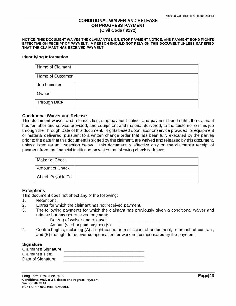
Merced Community College District
Long Form; Rev. June, 2018 Page|43 Conditional Waiver & Release on Progress Payment Section 00 65 01 NEXT UP PROGRAM REMODEL
CONDITIONAL WAIVER AND RELEASE ON PROGRESS PAYMENT
(Civil Code §8132) NOTICE: THIS DOCUMENT WAIVES THE CLAIMANT'S LIEN, STOP PAYMENT NOTICE, AND PAYMENT BOND RIGHTS EFFECTIVE ON RECEIPT OF PAYMENT. A PERSON SHOULD NOT RELY ON THIS DOCUMENT UNLESS SATISFIED THAT THE CLAIMANT HAS RECEIVED PAYMENT.
Identifying Information
Name of Claimant
Name of Customer
Job Location
Owner
Through Date
Conditional Waiver and Release This document waives and releases lien, stop payment notice, and payment bond rights the claimant has for labor and service provided, and equipment and material delivered, to the customer on this job through the Through Date of this document. Rights based upon labor or service provided, or equipment or material delivered, pursuant to a written change order that has been fully executed by the parties prior to the date that this document is signed by the claimant, are waived and released by this document, unless listed as an Exception below. This document is effective only on the claimant's receipt of payment from the financial institution on which the following check is drawn:
Maker of Check
Amount of Check
Check Payable To
Exceptions This document does not affect any of the following: 1. Retentions. 2. Extras for which the claimant has not received payment. 3. The following payments for which the claimant has previously given a conditional waiver and
release but has not received payment: Date(s) of waiver and release: _________________ Amount(s) of unpaid payment(s): _________________
4. Contract rights, including (A) a right based on rescission, abandonment, or breach of contract, and (B) the right to recover compensation for work not compensated by the payment.
Signature Claimant's Signature: __________________________________ Claimant's Title: __________________________________ Date of Signature: __________________________________
Merced Community College District
Long Form; Rev. June, 2018 Page|44 NEXT UP PROGRAM REMODEL
THIS PAGE INTENTIONALLY BLANK
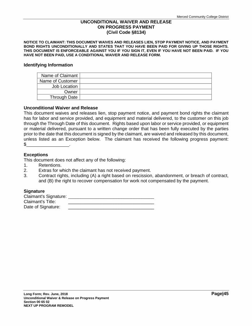
Merced Community College District
Long Form; Rev. June, 2018 Page|45 Unconditional Waiver & Release on Progress Payment Section 00 65 02 NEXT UP PROGRAM REMODEL
UNCONDITIONAL WAIVER AND RELEASE ON PROGRESS PAYMENT
(Civil Code §8134)
NOTICE TO CLAIMANT: THIS DOCUMENT WAIVES AND RELEASES LIEN, STOP PAYMENT NOTICE, AND PAYMENT BOND RIGHTS UNCONDITIONALLY AND STATES THAT YOU HAVE BEEN PAID FOR GIVING UP THOSE RIGHTS. THIS DOCUMENT IS ENFORCEABLE AGAINST YOU IF YOU SIGN IT, EVEN IF YOU HAVE NOT BEEN PAID. IF YOU HAVE NOT BEEN PAID, USE A CONDITIONAL WAIVER AND RELEASE FORM.
Identifying Information
Name of Claimant
Name of Customer
Job Location
Owner
Through Date
Unconditional Waiver and Release This document waives and releases lien, stop payment notice, and payment bond rights the claimant has for labor and service provided, and equipment and material delivered, to the customer on this job through the Through Date of this document. Rights based upon labor or service provided, or equipment or material delivered, pursuant to a written change order that has been fully executed by the parties prior to the date that this document is signed by the claimant, are waived and released by this document, unless listed as an Exception below. The claimant has received the following progress payment: $_________________. Exceptions This document does not affect any of the following: 1. Retentions. 2. Extras for which the claimant has not received payment. 3. Contract rights, including (A) a right based on rescission, abandonment, or breach of contract,
and (B) the right to recover compensation for work not compensated by the payment. Signature Claimant's Signature: __________________________________ Claimant's Title: __________________________________ Date of Signature: __________________________________
Merced Community College District
Long Form; Rev. June, 2018 Page|46 NEXT UP PROGRAM REMODEL
THIS PAGE INTENTIONALLY BLANK
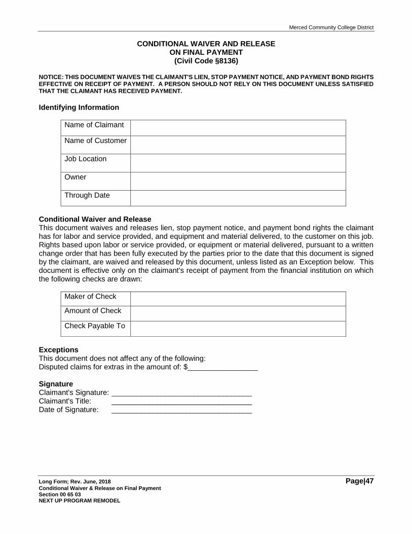
Merced Community College District
Long Form; Rev. June, 2018 Page|47 Conditional Waiver & Release on Final Payment Section 00 65 03 NEXT UP PROGRAM REMODEL
CONDITIONAL WAIVER AND RELEASE ON FINAL PAYMENT
(Civil Code §8136) NOTICE: THIS DOCUMENT WAIVES THE CLAIMANT'S LIEN, STOP PAYMENT NOTICE, AND PAYMENT BOND RIGHTS EFFECTIVE ON RECEIPT OF PAYMENT. A PERSON SHOULD NOT RELY ON THIS DOCUMENT UNLESS SATISFIED THAT THE CLAIMANT HAS RECEIVED PAYMENT.
Identifying Information
Name of Claimant
Name of Customer
Job Location
Owner
Through Date
Conditional Waiver and Release This document waives and releases lien, stop payment notice, and payment bond rights the claimant has for labor and service provided, and equipment and material delivered, to the customer on this job. Rights based upon labor or service provided, or equipment or material delivered, pursuant to a written change order that has been fully executed by the parties prior to the date that this document is signed by the claimant, are waived and released by this document, unless listed as an Exception below. This document is effective only on the claimant's receipt of payment from the financial institution on which the following checks are drawn:
Maker of Check
Amount of Check
Check Payable To
Exceptions This document does not affect any of the following: Disputed claims for extras in the amount of: $_________________ Signature Claimant's Signature: __________________________________ Claimant's Title: __________________________________ Date of Signature: __________________________________
Merced Community College District
Long Form; Rev. June, 2018 Page|48 NEXT UP PROGRAM REMODEL
THIS PAGE INTENTIONALLY BLANK
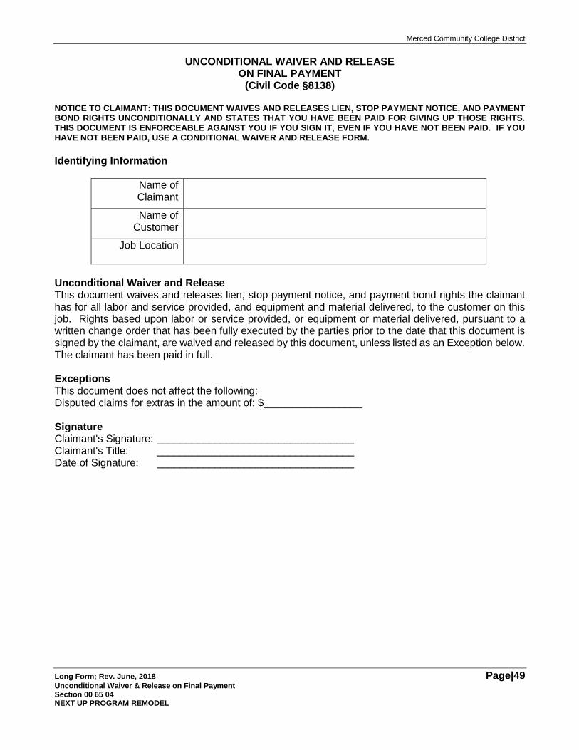
Merced Community College District
Long Form; Rev. June, 2018 Page|49 Unconditional Waiver & Release on Final Payment Section 00 65 04 NEXT UP PROGRAM REMODEL
UNCONDITIONAL WAIVER AND RELEASE ON FINAL PAYMENT
(Civil Code §8138) NOTICE TO CLAIMANT: THIS DOCUMENT WAIVES AND RELEASES LIEN, STOP PAYMENT NOTICE, AND PAYMENT BOND RIGHTS UNCONDITIONALLY AND STATES THAT YOU HAVE BEEN PAID FOR GIVING UP THOSE RIGHTS. THIS DOCUMENT IS ENFORCEABLE AGAINST YOU IF YOU SIGN IT, EVEN IF YOU HAVE NOT BEEN PAID. IF YOU HAVE NOT BEEN PAID, USE A CONDITIONAL WAIVER AND RELEASE FORM.
Identifying Information
Name of Claimant
Name of Customer
Job Location
Unconditional Waiver and Release This document waives and releases lien, stop payment notice, and payment bond rights the claimant has for all labor and service provided, and equipment and material delivered, to the customer on this job. Rights based upon labor or service provided, or equipment or material delivered, pursuant to a written change order that has been fully executed by the parties prior to the date that this document is signed by the claimant, are waived and released by this document, unless listed as an Exception below. The claimant has been paid in full. Exceptions This document does not affect the following: Disputed claims for extras in the amount of: $_________________ Signature Claimant's Signature: __________________________________ Claimant's Title: __________________________________ Date of Signature: __________________________________
Merced Community College District
Long Form; Rev. June, 2018 Page|50 NEXT UP PROGRAM REMODEL
THIS PAGE INTENTIONALLY BLANK
Merced Community College District
Long Form; Rev. June, 2018 Page|51 Contractor Guarantee; Section 00 65 36 NEXT UP PROGRAM REMODEL
Contractor Guarantee
District: Merced Community College District
Project Name: BID #2019-02 NEXT UP PROGRAM REMODEL
Contractor Name: _____________________________
The Contractor hereby warrants and guarantees to the District that all work, materials, equipment and workmanship provided, furnished or installed by or on behalf of Contractor in connection with the above-referenced Project (the "Work") have been provided, furnished and installed in strict conformity with the Contract Documents for the Work, including without limitation, the Drawings and the Specifications. Contractor further warrants and guarantees that all work, materials, equipment and workmanship as provided, furnished and/or installed are fit for use as specified and fulfill all applicable requirements of the Contract Documents including without limitation, the Drawings and the Specifications. Contractor shall, at its sole cost and expense, repair, correct and/or replace any or all of the work, materials, equipment and/or workmanship of the Work, together with any other items which may be affected by any such repairs, corrections or replacement, that may be unfit for use as specified or defective within a period of one (1) year from the date of the District's Final Acceptance of the Work, ordinary wear and tear and unusual abuse or neglect excepted.
In the event of the Contractor's failure and/or refusal to comply with the provisions of this Guarantee, within the period of time set forth in the Contract Documents after the District's issuance of the Notice to the Contractor of any defect(s) in the Work, materials, equipment or workmanship, Contractor authorizes the District, without further notice to Contractor, to repair, correct and/or replace any such defective item at the expense of the Contractor. The Contractor shall reimburse the District for all costs, expenses or fees incurred by the District in providing or performing such repairs, corrections or replacements within ten (10) days of the District's presentation of a demand to the Contractor for the same.
The provisions of this Guarantee and the provisions of the Contract Documents for the Work relating to the Contractor's Guarantee(s) and warranties relating to the Work shall be binding upon the Contractor's Performance Bond Surety and all successors or assigns of Contractor and/or Contractor's Performance Bond Surety.
The provisions of this Guarantee are in addition to, and not in lieu of, any provisions of the Contract Documents for the Work relating to the Contractor's guarantee(s) and warranties or any guarantee(s) or warranties provided by any material supplier or manufacturer of any equipment, materials or other items forming a part of, or incorporated into the Work, or any other guarantee or warranty obligation of the Contractor, prescribed, implied or imposed by law.
The undersigned individual executing this Guarantee on behalf of Contractor warrants and represents that he/she is duly authorized to execute this Guarantee on behalf of Contractor and to bind Contractor to each and every provision hereof.
Dated: ________________ By: ____________________________________ (Signature)
_______________________________________ (Typewritten or Handwritten Name)
_______________________________________ (Title)

Merced Community College District
Long Form; Rev. June, 2018 Page|52 NEXT UP PROGRAM REMODEL
THIS PAGE INTENTIONALLY BLANK
Merced Community College District
Long Form; Rev. June, 2018 Page|53 Contractor Certification of Subcontractor Claim; Section 00 65 37 NEXT UP PROGRAM REMODEL
CONTRACTOR CERTIFICATION OF SUBCONTRACTOR CLAIM
TO: ANTELOPE VALLEY COMMUNITY COLLEGE DISTRICT (“DISTRICT”)
RE: BID #2019-02 NEXT UP PROGRAM REMODEL (Project) YYYY (Contractor) ZZZZ (Subcontractor) Subcontractor Claim
This Contractor Certification of Subcontractor Claim is submitted by YYYY relating to BID #2019-02 NEXT UP PROGRAM REMODEL to the District on behalf of ZZZZ.
1. I am the ______________________________ of the Contractor in connection with the above-described Project.
2. The Subcontractor has submitted the accompanying Subcontractor Claim to the Contractor for presentation to the District pursuant to Public Contract Code §9204.
3. I have personally reviewed the entirety of the Subcontractor Claim and all substantiating documentation in support of the Subcontractor Claim.
4. The Subcontractor Claim is made by the Subcontractor in good faith.
5. The Subcontractor Claim is supported by reasonable documentation establishing entitlement to the relief requested and District liability therefor.
6. The Subcontractor Claim does not incorporate any request constituting a False Claim under applicable law, including the California False Claim Act (Government Code §12650 et. seq.).
7. I am authorized: (i) to execute this Certification on behalf of the Contractor; and (ii) to submit this Certification and the accompanying Subcontractor Claim to the District.
8. I have personal first-hand knowledge of all of the foregoing.
6. I declare under penalty of perjury under the laws of the State of California that the foregoing is true and correct.
7. Executed at __________________________, California, on ___________________, 20___.
8. ________________________________________
9. (Signature)
________________________________________ (Print Name)
________________________________________ (Title)
Merced Community College District
Long Form; Rev. June, 2018 Page|54 NEXT UP PROGRAM REMODEL
THIS PAGE INTENTIONALLY BLANK
Merced Community College District
Long Form; Rev. June, 2018 Page|55 General Conditions; Section 00 72 13 NEXT UP PROGRAM REMODEL
GENERAL CONDITIONS BID #2019-02 NEXT UP PROGRAM REMODEL
Merced Community College District
Long Form; Rev. June, 2018 Page|56 General Conditions; Section 00 72 13 NEXT UP PROGRAM REMODEL
GENERAL CONDITIONS TABLE OF CONTENTS
ARTICLE 1: DEFINITIONS
1.1 District.
1.2 Contractor.
1.3 Architect.
1.4 The Work.
1.5 The Project.
1.6 Surety.
1.7 Subcontractors; Sub-Subcontractors.
1.8 Material Supplier.
1.9 Drawings and Specifications.
1.10 Special Conditions; Supplemental Conditions.
1.11 Contract Documents.
1.12 Intent and Correlation of Contract Documents.
1.12.1 Work of the Contract Documents.
1.12.2 Technical Terms.
1.12.3 Conflict in Contract Documents.
1.13 Shop Drawings; Samples; Product Data (“Submittals”).
1.14 Division of State Architect (“DSA”).
1.15 District’s Inspector.
1.16 Contract Document Terms.
1.17 Contractor’s Superintendent.
1.18 Record Drawings.
1.19 Project Manager.
1.20 Construction Equipment.
1.21 Site.
1.22 Field Clarifications.
1.23 Defective or Non-Conforming Work.
1.24 Delivery.
1.25 Notice to Proceed.
1.26 Progress Reports; Verified Reports.
1.27 Laws.
1.28 Construction Change Directive.
ARTICLE 2: DISTRICT
2.1 Information Required of District.
2.1.1 Surveys; Site Information.
2.1.2 Permits, Licenses, Approvals.
2.1.3 Drawings and Specifications.
2.1.4 Furnishing of Information.
2.2 District’s Right to Stop the Work.
2.3 Partial Occupancy or Use.
2.3.1 District’s Right to Partial Occupancy.
2.4 No Acceptance of Defective or Nonconforming Work.
2.5 District’s Inspector.
2.5.1 Authority of District’s Inspector.
2.5.2 Limitations on District’s Inspector.
2.5.3 Contractor Access for District’s Inspector.
2.5.4 Contractor and District Responsibilities for Costs and Fees of District’s Inspector.
ARTICLE 3: ARCHITECT
3.1 Architect’s Administration of the Contract.
3.1.1 Administration of Contract.
3.1.2 Periodic Site Inspections.
3.1.3 Contractor Responsibility for Construction Means, Methods and Sequences.
3.1.4 Review of Applications for Payment.
3.1.5 Rejection of Work.
3.1.6 Submittals.
3.1.6.1 Architect’s Review.
3.1.6.2 Time for Architect’s Review.
3.1.7 Issuance of Construction Change Directive.
3.1.8 Changes to the Work; Change Orders.
3.1.9 Completion.
3.1.10 Interpretation of Contract Documents.
3.1.11 Request for Information.
3.2 Communications; Architect’s Role.
3.3 Termination of Architect; Substitute Architect.
3.4 Project Manager.
ARTICLE 4: THE CONTRACTOR
4.1 Contractor Review of Contract Documents.
4.1.1 Examination of Contract Documents.
4.1.2 Field Measurements.
4.1.3 Dimensions; Layouts and Field Engineering.
4.1.4 Work in Accordance With Contract Documents.
4.2 Site Investigation; Subsurface Conditions.
4.2.1 Contractor Investigation.
4.2.2 Subsurface Data.
4.2.3 Subsurface Conditions.
4.3 Supervision and Construction Procedures.
4.3.1 Supervision of the Work.
4.3.2 Responsibility for the Work.
4.3.3 Surveys.
Merced Community College District
Long Form; Rev. June, 2018 Page|57 General Conditions; Section 00 72 13 NEXT UP PROGRAM REMODEL
4.3.4 Construction Utilities.
4.3.5 Existing Utilities; Removal, Relocation and Protection.
4.3.6 Conferences and Meetings.
4.3.6.1 Pre-Construction Conference.
4.3.6.2 Progress Meetings.
4.3.6.3 Special Meetings.
4.3.6.4 Minutes of Meetings.
4.4 Labor and Materials.
4.4.1 Payment for Labor, Materials and Services.
4.4.2 Employee Discipline.
4.4.3 Compliance with Immigration Reform and Control Act of 1986.
4.4.4 Contractor’s Supervisory Personnel.
4.4.5 Prohibition on Harassment.
4.4.5.1 District’s Policy Prohibiting Harassment.
4.4.5.2 Contractor’s Adoption of Anti-Harassment Policy.
4.4.5.3 Prohibition on Harassment at the Site.
4.5 Taxes.
4.6 Permits, Fees and Notices; Compliance With Laws.
4.6.1 Payment of Permits, Fees.
4.6.2 Compliance With Laws.
4.6.3 Notice of Variation From Laws.
4.7 Submittals.
4.7.1 Purpose of Submittals.
4.7.2 Contractor’s Submittals.
4.7.2.1 Prompt Submittals.
4.7.2.2 Approval of Subcontractor Submittals.
4.7.2.3 Verification of Submittal Information.
4.7.2.4 Information Included in Submittals.
4.7.2.5 Contractor Responsibility for Deviations.
4.7.2.6 No Performance of Work Without Architect Review.
4.7.3 Architect Review of Submittals.
4.7.4 Deferred Approval Items.
4.8 Materials and Equipment.
4.8.1 Specified Materials, Equipment.
4.8.2 Approval of Substitutions or Alternatives.
4.8.3 Placement of Material and Equipment Orders.
4.8.4 District’s Right to Place Orders for Materials and/or Equipment.
4.8.5 Contractor and Subcontractor Communication.
4.9 Safety.
4.9.1 Safety Programs.
4.9.2 Contractor Safety Plan.
4.9.3 Safety Precautions.
4.9.4 Safety Signs, Barricades.
4.9.5 Safety Notices.
4.9.6 Safety Coordinator.
4.9.7 Emergencies.
4.9.8 Hazardous Materials.
4.9.8.1 General.
4.9.8.2 Prohibition on Use of Asbestos Construction Building Materials (“ACBMs”).
4.9.8.3 Disposal of Hazardous Materials.
4.10 Maintenance of Documents.
4.10.1 Documents at Site.
4.10.2 Maintenance of Record Drawings.
4.11 Use of Site.
4.12 Clean-Up.
4.13 Access to the Work.
4.14 Facilities and Information for the District’s Inspector.
4.14.1 Information to District’s Inspector.
4.14.2 Facilities for District’s Inspector.
4.15 Patents and Royalties.
4.16 Cutting and Patching.
4.17 Encountering of Hazardous Materials.
4.18 Wage Rates; Employment of Labor.
4.18.1 Determination of Prevailing Rates.
4.18.2 Payment of Prevailing Rates.
4.18.3 Prevailing Rate Penalty.
4.18.4 Certified Payroll Records.
4.18.4.1 Maintenance of Certified Payroll Records.
4.18.4.2 Submittal of Certified Payroll Records to Labor Commissioner.
4.18.4.3 Inspection of Certified Payroll Records.
4.18.5 Hours of Work.
4.18.5.1 Limits on Hours of Work.
4.18.5.2 Penalty for Excess Hours.
4.18.5.3 Contractor Responsibility.
4.18.6 Apprentices.
4.18.6.1 Employment of Apprentices.
4.18.6.2 Apprenticeship Certificate.
4.18.6.3 Ratio of Apprentices to Journeymen.
Merced Community College District
Long Form; Rev. June, 2018 Page|58 General Conditions; Section 00 72 13 NEXT UP PROGRAM REMODEL
4.18.6.4 Exemption From Ratios.
4.18.6.5 Contributions to Trust Funds.
4.18.6.6 Contractor’s Compliance.
4.18.7 Employment of Independent Contractors.
4.19 Assignment of Antitrust Claims.
4.20 Limitations Upon Site Activities.
4.21 Progress Reports; DSA Verified Reports.
4.21.1 DSA Verified Reports: Contractor Actions.
4.21.2 District Withholdings From Final Payment.
4.21.3 Progress Reports.
ARTICLE 5: SUBCONTRACTORS
5.1 Subcontracts.
5.2 Subcontractor DIR Contractor Registration
5.2.1 No Subcontractor Performance of Work Without DIR Registration.
5.2.2 Contractor Obligation to Verify Subcontractor DIR Registration Status
5.2.3 Contractor Obligation to Request Substitution of Listed Subcontractor Who Is Not DIR Registered Contractor
5.3 Substitution of Listed Subcontractor.
5.3.1 Substitution Process.
5.3.2 Responsibilities of Contractor Upon Substitution of Subcontractor.
5.4 Subcontractors’ Work.
ARTICLE 6: INSURANCE; INDEMNITY; BONDS
6.1 Workers’ Compensation Insurance; Employer’s Liability Insurance.
6.2 Commercial General Liability and Property Insurance.
6.3 Builder’s Risk “All-Risk” Insurance.
6.4 Insurance Requirements
6.4.1 Coverage Limits
6.4.2 Deductibles.
6.4.3 No Modification or Cancellation Without Prior Notice to District.
6.4.4 District Additional Insured.
6.4.5 Certifications of Insurance.
6.5 Subcontractor’s Insurance.
6.6 Maintenance of Insurance.
6.7 Contractor’s Insurance Primary.
6.8 Indemnity.
6.9 Payment Bond; Performance Bond.
ARTICLE 7: CONTRACT TIME
7.1 Substantial Completion of the Work Within Contract Time.
7.2 Progress and Completion of the Work.
7.2.1 Time of Essence.
7.2.2 Substantial Completion.
7.2.3 Correction or Completion of the Work After Substantial Completion.
7.2.3.1 Punchlist.
7.2.3.2 Time for Completing Punchlist Items. Final Completion.
7.2.4 Contractor Responsibility for Multiple Inspections.
7.2.5 Final Acceptance.
7.3 Construction Schedule.
7.3.1 Submittal of Preliminary Construction Schedule.
7.3.2 Review of Preliminary Construction Schedule.
7.3.3 Preparation and Submittal of Contract Construction Schedule.
7.3.4 Revisions to Approved Construction Schedule.
7.3.5 Updates to Approved Construction Schedule.
7.3.6 Contractor Responsibility for Construction Schedule.
7.4 Adjustment of Contract Time.
7.4.1 Excusable Delays.
7.4.2 Compensable Delays.
7.4.3 Unexcusable Delays.
7.4.4 Adjustment of Contract Time.
7.4.4.1 Procedure for Adjustment of Contract Time.
7.4.4.2 Limitations Upon Adjustment of Contract Time on Account of Delays.
7.5 Liquidated Damages.
ARTICLE 8: CONTRACT PRICE
8.1 Contract Price.
8.2 Cost Breakdown.
8.3 Progress Payments.
8.3.1 Applications for Progress Payments.
8.3.2 Payment Application Review for Determination of Proper Payment Application.
8.3.3 Verification of Work Completed.
8.3.4 District’s Disbursement of Progress Payments.
8.3.4.1 Timely Disbursement of
Merced Community College District
Long Form; Rev. June, 2018 Page|59 General Conditions; Section 00 72 13 NEXT UP PROGRAM REMODEL
Progress Payments.
8.3.4.2 Untimely Disbursement of Progress Payments.
8.3.4.3 District’s Right to Disburse Payments by Joint Checks.
8.3.4.4 No Waiver of Defective or Non-Conforming Work.
8.3.5 Progress Payments for Changed Work.
8.3.6 Materials or Equipment Not Incorporated Into the Work.
8.3.6.1 Limitations Upon Payment.
8.3.6.2 Materials or Equipment Delivered and Stored at the Site.
8.3.6.3 Materials or Equipment Not Delivered or Stored at the Site.
8.3.7 Exclusions From Progress Payments.
8.3.8 Title to Work.
8.3.9 Substitute Security for Retention.
8.4 Final Payment.
8.4.1 Application for Final Payment.
8.4.2 Conditions Precedent to Disbursement of Final Payment.
8.4.3 Disbursement of Final Payment.
8.4.4 Waiver of Claims.
8.4.5 Claims Asserted After Final Payment.
8.5 Withholding of Payments.
8.6 Payments to Subcontractors.
8.7 Computerized Job Cost Reporting System.
8.7.1 Job Cost Reporting.
8.7.2 Job Cost Reporting System Requirements.
8.7.3 Job Cost System Information.
ARTICLE 9: CHANGES
9.1 Changes in the Work.
9.2 Construction Change Directive.
9.3 Oral Order of Change in the Work.
9.4 Contractor Submittal of Data.
9.5 Adjustment to Contract Price and Contract Time on Account of Changes to the Work.
9.5.1 Adjustment to Contract Price.
9.5.1.1 Mutual Agreement.
9.5.1.2 Determination by the District.
9.5.1.3 Basis for Adjustment of
Contract Price.
9.5.1.3.1 Labor.
9.5.1.3.2 Materials and Equipment.
9.5.1.3.3 Construction Equipment.
9.5.1.3.4 Mark-up on Costs of Changes to the Work.
9.5.1.4 Contractor Maintenance of Records.
9.5.2 Adjustment to Contract Time.
9.5.3 Addition or Deletion of Alternate Bid Item(s).
9.6 Change Orders.
9.7 Contractor Notice of Changes.
9.8 Disputed Changes.
9.9 Emergencies.
9.10 Minor Changes in the Work.
9.11 Unauthorized Changes.
ARTICLE 10: SEPARATE CONTRACTORS
10.1 District’s Right to Award Separate Contracts.
10.2 District’s Coordination of Separate Contractors.
10.3 Mutual Responsibility.
10.4 Discrepancies or Defects.
ARTICLE 11: TESTS AND INSPECTIONS
11.1 Tests; Inspections; Observations.
11.1.1 Contractor’s Notice.
11.1.2 Cost of Tests and Inspections.
11.1.3 Testing/Inspection Laboratory.
11.1.4 Additional Tests, Inspections and Approvals.
11.2 Delivery of Certificates.
11.3 Timeliness of Tests, Inspections and Approvals.
ARTICLE 12: UNCOVERING AND CORRECTION OF WORK
12.1 Inspection of the Work.
12.1.1 Access to the Work.
12.1.2 Limitations Upon Inspections.
12.2 Uncovering of Work.
12.3 Rejection of Work.
12.4 Correction of Work.
12.5 Removal of Non-Conforming or Defective Work.
12.6 Failure of Contractor to Correct Work.
12.7 Acceptance of Defective or Non-
Merced Community College District
Long Form; Rev. June, 2018 Page|60 General Conditions; Section 00 72 13 NEXT UP PROGRAM REMODEL
Conforming Work.
ARTICLE 13: WARRANTIES
13.1 Workmanship and Materials.
13.2 Warranty Work.
13.3 Guarantee.
13.4 Survival of Warranties; Surety Obligations.
ARTICLE 14: SUSPENSION OF WORK
14.1 District’s Right to Suspend Work.
14.2 Adjustments to Contract Price and Contract Time.
ARTICLE 15: TERMINATION
15.1 Termination for Cause.
15.1.1 District’s Right to Terminate.
15.1.2 District’s Rights Upon Termination.
15.1.3 Completion by the Surety.
15.1.4 Assignment and Assumption of Subcontracts.
15.1.5 Costs of Completion.
15.1.6 Contractor Responsibility for Damages.
15.1.7 Conversion to Termination for Convenience.
15.1.8 District’s Rights Cumulative.
15.2 Termination for Convenience of the District.
ARTICLE 16: MISCELLANEOUS
16.1 Governing Law.
16.2 Marginal Headings; Interpretation.
16.3 Successors and Assigns.
16.4 Cumulative Rights and Remedies; No Waiver.
16.5 Severability.
16.6 No Assignment by Contractor.
16.7 Gender and Number.
16.8 Independent Contractor Status.
16.9 Notices.
16.10 Disputes; Continuation of Work.
16.11 Dispute/Claims Resolution.
16.11.1 Public Contract Code §9204 Claims Resolution Procedures.
16.11.1.1Claim Defined.
16.11.1.2Claim Documentation.
16.11.1.3District Claim Review Statement.
16.11.1.4Meet and Confer.
16.11.1.4.1 Meet and Confer Demand.
16.11.1.4.2 Meet and Confer Statement.
16.11.1.5Non-Binding Mediation
16.11.1.5.1 Contractor Initiation.
16.11.1.5.2 Mediator Selection.
16.11.1.5.3 Mediation Procedures.
16.11.1.5.4 Mediation Costs.
16.11.1.5.5 Post-Mediation Disputed Claims.
16.11.1.5.6 Waiver.
16.11.2 Payment of Undisputed Claims.
16.11.3 Subcontractor Claims.
16.11.3.1 Subcontractor Claim Submittal.
16.11.3.2 Contractor Certification of Subcontractor Claim.
16.11.3.3 District Review of Subcontractor Claim.
16.11.3.4 Disputed Subcontractor Claims.
16.11.4 Government Code Claim Requirements.
16.11.5 Section 20104.4 Dispute Resolution Procedures; Claims Less Than $375,000.
16.11.5.1 Binding Arbitration of Claims Exceeding $375,000
16.11.5.1.1 JAMS Arbitration.
16.11.5.2 Demand for Arbitration.
16.11.5.3 Discovery.
16.11.5.4 Arbitration Award.
16.11.5.5 Arbitration Fees and Expenses.
16.11.5.6 Limitation on Arbitrator.
16.11.6 Inapplicability to Bid Bond.
16.12 Limitation on Special/Consequential Damages.
16.13 Capitalized Terms.
16.14 Attorneys’ Fees.
16.15 Provisions Required by Law Deemed Inserted.
16.16 Days.
16.17 Entire Agreement.
Merced Community College District
Long Form; Rev. June, 2018 Page|61 General Conditions; Section 00 72 13 NEXT UP PROGRAM REMODEL
GENERAL CONDITIONS
ARTICLE 1: DEFINITIONS 1.1 District. The “District” refers to Merced Community College District and unless otherwise stated, includes the District’s authorized representatives, including the Project Manager, if a Project Manager is designated, the District’s Board of Trustees and the District’s officers, employees, agents and representatives.
1.2 Contractor. The Contractor is the person or entity identified as such in the Agreement; references to “Contractor” include the Contractor’s authorized representative.
1.3 Architect. The Architect is the person or entity identified as such in the Agreement; references to the “Architect” include, as required by context of usage, the Architect’s employees and authorized representative(s) and the Architect’s Consultants and their employees and authorized representative(s).
1.4 The Work. The Work is the construction and services required by the Contract Documents, whether completed or partially completed, and includes all other labor, materials, equipment or services provided or to be provided by the Contractor to fulfill the Contractor’s obligations under the Contract Documents. The Work may constitute the whole or a part of the Project.
1.5 The Project. The Project is the total construction of which the Work performed by the Contractor under the Contract Documents may be the whole or a part of the Project and which may include construction by the District or by separate contractors.
1.6 Surety. The Surety is the person or entity that executes, as surety, the Contractor’s Labor and Material Payment Bond and/or Performance Bond.
1.7 Subcontractors; Sub-Subcontractors. A Subcontractor is a person or entity who has a direct contract with the Contractor to perform a portion of the Work. “Subcontractor” does not include a separate contractor to the District or subcontractors of any separate contractor. A Sub-Subcontractor is a person or entity of any tier, who has a direct or indirect contract with a Subcontractor to perform a portion of the Work at the Site. References to “Subcontractor” herein include all subcontractors of any tier.
1.8 Material Supplier. A Material Supplier is any person or entity who only furnishes materials, equipment or supplies for the Work without fabricating, installing or consuming them in the Work.
1.9 Drawings and Specifications. The Drawings are the graphic and pictorial portions of the Contract Documents, wherever located and whenever issued, showing generally, the design, location and dimensions of the Work and may include without limitation, plans, elevations, sections, details, schedules or diagrams. The Specifications are that portion of the Contract Documents consisting of the written requirements for materials, equipment, construction systems, standards, criteria and workmanship for the Work and related services. The Drawings and Specifications are intended to delineate and describe the Work and its component parts so as to permit skilled and competent contractors to bid upon the Work and prosecute the same to completion.
1.10 Special Conditions; Supplemental Conditions. Special Conditions and/or Supplemental Conditions, if any are special or supplemental provisions, not otherwise provided for in the Agreement or the General Conditions.
1.11 Contract Documents. The Contract Documents consist of the Agreement between the District and the Contractor, Conditions of the Contract (whether General, Special, Supplemental or otherwise), Drawings, Specifications, including addenda thereto issued prior to execution of the Agreement and any other documents listed in the Agreement. The Contract Documents shall include modifications issued after execution of the Agreement. The Contract Documents form the Contract for Construction.
Merced Community College District
Long Form; Rev. June, 2018 Page|62 General Conditions; Section 00 72 13 NEXT UP PROGRAM REMODEL
1.12 Intent and Correlation of Contract Documents.
1.12.1 Work of the Contract Documents. The intent of the Contract Documents is to include all items necessary for the proper execution and completion of the Work by the Contractor. The Contract Documents are complementary and what is required by one shall be as binding as if required by all; performance by the Contractor shall be required to the extent consistent with the Contract Documents and reasonably inferable therefrom as being necessary to produce the intended results. Organization of the Specifications into divisions, sections or articles, and the arrangement of Drawings shall not control the Contractor in dividing the Work among Subcontractors or in establishing the extent of Work to be performed by any trade. Where any portion of the Contract Documents is silent and information appears elsewhere in the Contract Documents, such other portions of the Contract Documents shall control.
1.12.2 Technical Terms. Unless otherwise stated in the Contract Documents, words or terms which have well-known technical or construction industry meanings are used in the Contract Documents in accordance with such recognized meanings.
1.12.3 Conflict in Contract Documents. Conflicts, inconsistencies or ambiguities in the Contract Documents shall be resolved by the Architect in accordance with Article 3.1.9 of the General Conditions; where conflicts or inconsistencies arise between the Drawings and the Specifications, in resolving such conflicts or inconsistencies, the Architect will be governed generally by the following standards: the Drawings are intended to describe matters relating to placement, type, quantity and the like; the Specifications are intended to describe matters relating to quality, materials, compositions, manufacturers and the like. If conflicts exist between portions of the Contract Documents regarding the quality of any item, product, equipment or materials, unless otherwise directed or authorized by the District, the Contractor shall provide the item, product, equipment or material of the highest or more stringent quality.
1.13 Shop Drawings; Samples; Product Data (“Submittals”). Shop Drawings are diagrams, schedules and other data specially prepared for the Work by the Contractor or a Subcontractor, Material Supplier, or others to illustrate some portion of the Work. Samples are physical examples of materials, equipment or workmanship forming a part of, or to be incorporated into the Work. Product Data are illustrations, standard schedules, performance charts, instructions, brochures, diagrams and other information furnished by the Contractor to illustrate materials or equipment for some portion of the Work. Shop Drawings, Samples and Product Data prepared or furnished by the Contractor, Subcontractors or Material Suppliers are collectively referred to as “Submittals”.
1.14 Division of State Architect (“DSA”). DSA is the California Division of the State Architect including without limitation DSA’s Office of Construction Services, Office of Design Services and the Office of Regulatory Services; references to the DSA in the Contract Documents shall mean the DSA, its offices and its authorized employees and agents. The authority of the DSA over the Work and the performance thereof shall be as set forth in the Contract Documents and Title 24 of the California Code of Regulations.
1.15 District’s Inspector. The District’s Inspector is the individual designated and employed by the District in accordance with the requirements of Title 24 of the California Code of Regulations. The District’s Inspector shall be authorized to act on behalf of the District as provided for in the Contract Documents and in Title 24 of the California Code of Regulations, as the same may be amended from time to time.
1.16 Contract Document Terms. The term “provide” means “provide complete in place” or to “furnish and install” such item. Unless otherwise provided in the Contract Documents, the terms “approved;” “directed;” “satisfactory;” “accepted;” “acceptable;” “proper;” “required;” “necessary” and “equal” shall mean as approved, directed, satisfactory, accepted, acceptable, proper, required, necessary and equal, in the opinion of the Architect. The term “typical” as used in the Drawings shall require the installation
Merced Community College District
Long Form; Rev. June, 2018 Page|63 General Conditions; Section 00 72 13 NEXT UP PROGRAM REMODEL
or furnishing of such item(s) of the Work designated as “typical” in all other areas similarly marked as “typical”; Work in such other areas shall conform to that shown as “typical” or as reasonably inferable therefrom.
1.17 Contractor’s Superintendent. The Contractor’s Superintendent is the individual employed by the Contractor whose principal responsibility shall be the supervision and coordination of the Work; the Contractor’s Superintendent shall not perform routine construction labor.
1.18 Record Drawings. The Record Drawings are a set of the Drawings marked by the Contractor during the performance of the Work to indicate completely and accurately the actual as-built condition of the Work. The Record Drawings shall be sufficient for a capable and qualified draftsman to modify the Drawings to reflect and indicate the Work actually in place at Final Completion of the Work.
1.19 Project Manager. The Project Manager, if any, is the individual or entity designated as such in the Special Conditions. The Project Manager is an independent contractor retained by the District and shall be authorized and empowered to act on behalf of the District. In the event that a Project Manager is not designated in the Special Conditions, the District reserves the right to designate a Project Manager at any time during Contractor’s performance of the Work. The District reserves the right to remove or replace the Project Manager during Contractor’s performance of the Work. The designation of a Project Manager, if one has not been designated in the Special Conditions, or the removal or replacement of the designated Project Manager shall not result in adjustment of the Contract Price or the Contract Time or otherwise affect, limit or restrict Contractor’s obligations hereunder.
1.20 Construction Equipment. Construction Equipment is equipment utilized for the performance of any portion of the Work, but which is not incorporated into the Work.
1.21 Site. The Site is the physical area designated in the Contract Documents for Contractor’s performance, construction and installation of the Work.
1.22 Field Clarifications. A written or graphic document consisting of supplementary details, instructions or information issued on behalf of the District which clarifies or supplements the Contract Documents and which becomes a part of the Contract Documents upon issuance. Field Clarifications do not constitute an adjustment of the Contract Time or the Contract Price, unless a Change Order relating to a Field Clarification is authorized and issued under the Contract Documents.
1.23 Defective or Non-Conforming Work. Defective or Non-Conforming Work is any Work which is unsatisfactory, faulty or deficient by: (i) not conforming to the requirements of the Contract Documents; (ii) not conforming to the standards of workmanship of the applicable trade or industry; (iii) not being in compliance with the requirements of any inspection, reference, standard, test, or approval required by the Contract Documents; or (iv) damage occurring prior to Final Completion of all of the Work.
1.24 Delivery. Delivery used in conjunction with any equipment, materials or other items to be incorporated into the Work shall mean the unloading and storage in a protected condition at the Site pending incorporation into the Work.
1.25 Notice to Proceed. The Notice to Proceed is the written notice issued by or on behalf of the District to the Contractor authorizing the Contractor to proceed with commencement of the Work and which establishes the date for commencement of the Contract Time.
1.26 Progress Reports; Verified Reports. Progress Reports, if required, are written reports prepared by the Contractor and periodically submitted to the District in the form and content as required by the Contract Documents. Verified Reports are periodic written reports prepared by the Contractor and submitted to the DSA; Verified Reports shall be in such form and content as required by the applicable provisions of Title 24 of the California Code of Regulations. A material obligation of the Contractor is the preparation of complete and accurate Progress Reports, if required, and Verified Reports as well as the timely submission of the same.
Merced Community College District
Long Form; Rev. June, 2018 Page|64 General Conditions; Section 00 72 13 NEXT UP PROGRAM REMODEL
1.27 Laws. Laws refer to all laws, ordinances, codes, rules and/or regulations promulgated by any governmental or quasi-governmental agency with jurisdiction over any portion of the Work and which apply to any portion of the Work, including those in effect as of the execution of the Agreement, amendments thereto and subsequently enacted Laws that take effect during the performance of the Work. No adjustment of the Contract Time or the Contract Price shall be allowed for the Contractor’s compliance with the Laws.
1.28 Construction Change Directive. A Construction Change Directive is a written instrument issued by or on behalf of the District to the Contractor directing a Change to the Work prior to the Contractor and District reaching full agreement on an adjustment of the Contract Time and/or Contract Price on account of such Change. A material obligation of the Contractor is timely performance of Work noted in a Construction Change Directive.
ARTICLE 2: DISTRICT
2.1 Information Required of District.
2.1.1 Surveys; Site Information. Information, if any, concerning physical characteristics of the Site, including without limitation, surveys, soils reports, and utility locations, to be provided by the District are set forth in the Contract Documents. Information not provided by the District or necessary information in addition to that provided by the District concerning physical characteristics of the Site which is required shall be obtained by Contractor without adjustment to the Contract Price or the Contract Time.
2.1.2 Permits, Licenses, Approvals. Except as otherwise provided in the Contract Documents, the District shall secure and pay for necessary approvals, easements, assessments and charges required for construction, use or occupancy of permanent structures or for permanent changes in existing facilities which relate to the Work of the Contractor under the Contract Documents. If permits, licenses, approvals or similar approvals relating to the Work, or the installation/construction thereof are designated as the responsibility of the Contractor under the Contract Documents, the Contractor shall obtain the same without adjustment of the Contract Price or the Contract Time.
2.1.3 Drawings and Specifications. Except as otherwise provided for in the Contract Documents, the District shall furnish the Contractor, free of charge, the number of copies of the Drawings and the Specifications as set forth in the Special Conditions. All of the Drawings and the Specifications provided by the District to the Contractor remain the property of the District; the Contractor shall not use the Drawings or the Specifications in connection with any other work of improvement other than the Work.
2.1.4 Furnishing of Information. Information or services to be provided by the District under the Contract Documents shall be furnished by the District with reasonable promptness to avoid delay in the orderly progress of the Work. Information about existing conditions furnished by the District under the Contract Documents is obtained from sources believed to be reliable, but the District neither guarantees nor warrants that such information is complete and accurate. The Contractor shall verify all information provided by the District. If the Contract Documents depict existing conditions on or about the Site, or the Work involves the renovation, removal or remodeling of existing improvements or the Work involves any tie-in or other connection with existing improvements, the conditions and/or existing improvements depicted in the Contract Documents are as they are believed to exist. The Contractor shall bear the risk of any variations between conditions or existing improvements depicted in the Contract Documents and those conditions or existing improvements actually encountered in the performance of the Work. The existence of any variations between conditions or existing improvements depicted in the Contract Documents and those actually encountered in the performance of the Work shall not result in any District liability therefor, nor shall any such variations result in an adjustment of the
Merced Community College District
Long Form; Rev. June, 2018 Page|65 General Conditions; Section 00 72 13 NEXT UP PROGRAM REMODEL
Contract Time or the Contract Price.
2.2 District’s Right to Stop the Work. In addition to the District’s right to suspend the Work or terminate the Contract pursuant to the Contract Documents, the District, may, by written order, direct the Contractor to stop the Work, or any portion thereof, until the cause for such stop work order has been eliminated if the Contractor: (i) fails to correct Work which is not in conformity and in accordance with the requirements of the Contract Documents, or (ii) otherwise fails to carry out the Work in conformity and accordance with the Contract Documents. The right of the District to stop the Work hereunder shall not be deemed a duty on the part of the District to exercise such right for the benefit of the Contractor or any other person or entity, nor shall the District’s exercise of such right: (i) waive or limit the exercise of any other right or remedy of the District under the Contract Documents or the Laws; or (ii) result in adjustment of the Contract Time or Contract Price.
2.3 Partial Occupancy or Use. 2.3.1 District’s Right to Partial Occupancy. The District may occupy or use any completed or partially completed portion of the Work, provided that: (i) the District has obtained the consent of, or is otherwise authorized by, public authorities with jurisdiction thereof, to so occupy or use such portion of the Work and (ii) the District and the Contractor have accepted, in writing, the responsibilities assigned to each of them for security, maintenance, utilities, damage to the Work, insurance, the period for correction of the Work and commencement of warranties required by the Contract Documents for such portion of the Work partially used or occupied by the District. If the Contractor and the District are unable to agree upon the matters set forth in (ii) above, the District may nevertheless use or occupy any portion of the Work, with the responsibility for such matters subject to resolution in accordance with the Contract Documents. Immediately prior to such partial occupancy or use of the Work, or portions thereof, the District, the District’s Inspector, the Contractor and the Architect shall jointly inspect the portions of the Work to be occupied or to be used to determine and record the condition of the Work. Repairs, replacements or other corrective action noted in such inspection shall be promptly performed and completed by the Contractor so that the portion of the Work to be occupied or used by the District is in conformity with the requirements of the Contract Documents and the District’s occupancy or use thereof is not impaired. The District’s use or occupancy of the Work or portions thereof pursuant to the preceding shall not be deemed “completion” of the Work as that term is used in Public Contract Code §7107.
2.4 No Acceptance of Defective or Nonconforming Work. The District’s partial occupancy or use of the Work or any portion thereof, shall not constitute the District’s acceptance of the Work which is defective or non-conforming.
2.5 District’s Inspector. 2.5.1 Authority of District’s Inspector. In addition to the authority and rights of the District’s Inspector as provided for elsewhere in the Contract Documents and/or the Laws, all of the Work shall be performed under the observation of the District’s Inspector. The foregoing notwithstanding, the Contractor shall not perform any Work deviating from the Contract Documents solely on the basis of direction by the District’s Inspector; such deviations shall be deemed defective or non-conforming Work subject to correction or replacement at the sole cost of the Contractor and without adjustment of the Contract Time. The performance of the duties of the District’s Inspector shall not relieve or limit the Contractor’s performance of its obligations under the Contract Documents. 2.5.2 Limitations on District’s Inspector. The does not have authority to interpret the Contract Documents or to modify the Work depicted in the Contract Documents. The District’s Inspector has no authority relative to the content or scope of the Contractor’s safety plan/program. The Contractor shall not perform any Work deviating from the Contract Documents solely on the basis of direction by the District’s Inspector; such deviations shall be deemed Defective or Non-
Merced Community College District
Long Form; Rev. June, 2018 Page|66 General Conditions; Section 00 72 13 NEXT UP PROGRAM REMODEL
Conforming Work subject to correction or replacement at the sole cost of the Contractor and without adjustment of the Contract Time.
2.5.3 Contractor Access for District’s Inspector. The Contractor shall provide the District’s Inspector with access to all parts of the Work at any time, wherever located and whether partially or completely fabricated, manufactured, furnished or installed.
2.5.4 Contractor and District Responsibilities for Costs and Fees of District’s Inspector. The District is responsible only for payment of the fees of the District’s Inspector for standard eight (8) hour work day Mondays through Fridays, excepting holiday days (“District’s Inspector Standard Workdays”). Unless the District directs the Contractor to perform Work exceeding the District’s Inspector Standard Workdays, for any Work performed by the Contractor outside the District’s Inspector Standard Workdays, the Contractor shall be responsible for payment of District’s Inspector fees for District’s Inspector services relating to such Work. All services provided by the District’s Inspector exceeding an eight (8) hour workday Mondays through Fridays and/or the first eight (8) hours on Saturdays shall be at one and one-half (1½) times the District’s Inspector’s basic hourly rate. All hours of service provided by the District’s Inspector in excess of eight (8) hours on Saturdays, and all hours of service provided by the District’s Inspector on holiday days or on Sundays are at two (2) times the District’s Inspector’s basic hourly rate. Fees for services provided by the District’s Inspector beyond the District’s Inspector Standard Workdays set forth above are the sole responsibility of the Contractor; the District may deduct such fees from the Contract Price then or thereafter due the Contractor.
ARTICLE 3: ARCHITECT
3.1 Architect’s Administration of the Contract. 3.1.1 Administration of Contract. The Architect will provide administration of the Contract as described in the Contract Documents, and will be one of the District’s representatives during construction until the time that Final Payment. The Architect will advise and consult with the District, the Project Manager, if any, and the District’s Inspector with respect to the administration of the Contract and the Work. The Architect is authorized to act on behalf of the District to the extent provided for in the Contract Documents; and shall have the responsibilities and authority established by the Laws. 3.1.2 Periodic Site Inspections. The Architect will visit the Site at intervals appropriate to the stage of construction to become generally familiar with the progress and quality of the completed Work and to determine, in general, if the Work is being performed in a manner indicating that the Work, when completed, will be in accordance with the Contract Documents. The Architect is not required to make exhaustive or continuous Site inspections to check quality or quantity of the Work. On the basis of Site observations as an architect, the Architect will keep the District informed of the progress of the Work, and will endeavor to guard the District against defects and deficiencies in the Work. 3.1.3 Contractor Responsibility for Construction Means, Methods and Sequences. The Architect will not have control over or charge of and will not be responsible for construction means, methods, techniques, sequences or procedures, or for safety precautions and programs in connection with the Work, these being solely the Contractor’s responsibility. The Architect will not have control over or charge of and will not be responsible for acts or omissions of the Contractor, Subcontractors, or their agents or employees, or of any other persons performing portions of the Work. 3.1.4 Review of Applications for Payment. Pursuant to Article 8 hereof, the Architect will review the Contractor’s Payment Applications and for Final Payment, evaluate the extent of Work performed and verify to the District the amount properly due the Contractor on such Application for Payment. 3.1.5 Rejection of Work. The Architect is authorized to reject Work which is defective or does
Merced Community College District
Long Form; Rev. June, 2018 Page|67 General Conditions; Section 00 72 13 NEXT UP PROGRAM REMODEL
not conform to the requirements of the Contract Documents. Whenever the Architect considers it necessary or advisable, for implementation of the intent of the Contract Documents, the Architect is authorized to require additional inspections or testing of the Work, whether or not such Work is fabricated, installed or completed. Neither this authority of the Architect nor a decision made in good faith by the Architect to exercise or not to exercise such authority shall modify requirements of the Contract Documents or any obligation of the Contractor under the Contract Documents. 3.1.6 Submittals.
3.1.6.1 Architect’s Review. The Architect will review and approve or take other appropriate action upon Submittals for the limited purpose of checking for general conformance with information given and the design concept expressed in the Contract Documents. Review of Submittals is not for the purpose of determining the accuracy and completeness of other details such as dimensions and quantities, or for substantiating instructions for installation or performance of equipment or systems, all of which remain the responsibility of the Contractor. The Architect’s review of the Contractor’s Submittals shall not: (i) modify or limit the Contractor’s obligations under the Contract Documents; (ii) requirements of the Contract Documents relating to the Work; (iii) approval of safety measures, programs or precautions; or (iv) construction means, methods, techniques, sequences or procedures. The Architect’s acceptance of a specific item in a Submittal shall not indicate approval of an assembly of which the item is a component with the Submittal(s) required and relating to such assembly have been reviewed by the Architect. 3.1.6.2 Time for Architect’s Review. The Architect’s review of Submittals will be conducted promptly so as not to delay or hinder the progress of the Work or the activities of the Contractor, the District or the District’s separate contractors while allowing sufficient time, in the Architect’s reasonable professional judgment, to permit adequate review of Submittals. The foregoing notwithstanding, the Architect’s review and return of Submittals will conform with the time limits and other conditions, if any, set forth in the Specifications or the Submittal Schedule if the Submittal Schedule is required by other provisions of the Contract Documents.
3.1.7 Issuance of Construction Change Directive. The Architect is authorized to issue Construction Change Directives. 3.1.8 Changes to the Work; Change Orders. The Architect will prepare Change Orders, and may authorize minor Changes in the Work which do not result in adjustment of the Contract Time or the Contract Price. 3.1.9 Completion. In conjunction with the District, District’s Inspector, Project Manager, if any, and the Contractor, the Architect will conduct observations of the Work to determine the date(s) of Substantial Completion and Final Completion. If the District does not designate a Project Manager for the Work, the Architect shall: (i) be authorized to enforce the Contractor’s close-out obligations; and (ii) receive from the Contractor and the records, written warranties and related close-out materials assembled by the Contractor in accordance with the Contract Documents. 3.1.10 Interpretation of Contract Documents. The Architect will interpret and decide matters concerning the requirements of the Contract Documents on written request of either the District or the Contractor. The Architect’s response to such requests will be made with reasonable promptness and within the time limits agreed upon, if any. If no agreement is reached establishing the time for the Architect’s review and response to requests under this Article 3.1.10, the Architect shall be afforded a fifteen (15) day period after receipt of such request to review and respond thereto. Interpretations and decisions of the Architect will: (i) be consistent with the intent of and reasonably inferable from the Contract Documents and will be in writing or in the form of drawings. When making such interpretations and decisions; (ii) endeavor to secure faithful performance by both the District and the Contractor; (iii) not show partiality to
Merced Community College District
Long Form; Rev. June, 2018 Page|68 General Conditions; Section 00 72 13 NEXT UP PROGRAM REMODEL
either the District or Contractor; and (iv) not result in liability for results of interpretations or decisions so rendered in good faith. The Architect’s decisions on matters relating to aesthetic effect will be final if consistent with the intent expressed in the Contract Documents. 3.1.11 Request for Information. If the Contractor encounters any condition which the Contractor believes, in good faith and with reasonable basis, is the result of an ambiguity, conflict, error or omission in the Contract Documents (collectively “the Conditions”), Contractor shall timely notify the Architect, in writing, of the Conditions encountered and to request information from the Architect necessary to address and resolve any such Conditions before proceeding with any portion of the Work affected or which may be affected by such Conditions. If the Contractor fails to timely notify the Architect in writing of any Conditions encountered and the Contractor proceeds to perform any portion of the Work containing or affected by such Conditions the Contractor shall bear all costs associated with or required to correct, remove, or otherwise remedy any portion of the Work affected thereby without adjustment of the Contract Time or the Contract Price. In requesting information of the Architect to address and resolve any Conditions the Contractor shall act with promptness in submitting any such written request so as to allow the Architect a reasonable period of time to review, evaluate and respond to any such request, taking into account the then current status of the progress and completion of the Work and the actual or potential impact of any such Conditions upon the completion of the Work within the Contract Time. The Contract Time shall not be subject to adjustment in the event that the Contractor shall fail to timely request information from the Architect. The Architect’s responses to any such Contractor request for information shall conform to the standards and time frame set forth in Article 3.1.10 of these General Conditions. The foregoing provisions notwithstanding, if the Architect reasonably determines that any of Contractor’s request(s) for information: (i) does not reflect adequate or competent supervision or coordination by the Contractor or any Subcontractor; (ii) does not reflect the Contractor’s adequate or competent knowledge of the requirements of the Work or the Contract Documents; or (iii) is not justified for any other reason, Contractor shall be liable to the District for all costs incurred by the District associated with the processing, reviewing, evaluating and responding to any such request for information, including without limitation, fees of the Architect. In responding to any of Contractor’s request(s) for information, the Architect shall, in the response, indicate if the Architect has made the determination pursuant to the preceding sentence and, if so, the costs to be borne by the Contractor for the processing, review, evaluation and response to the request for information. Thereafter, the District is authorized to deduct such costs from any portion of the Contract Price then or thereafter due the Contractor.
3.2 Communications; Architect’s Role. All communications regarding the Work, the performance thereof or the Contract Documents shall be in writing; verbal communications shall be reduced to writing. If the District does not designate a Project Manager for the Work, communications between the Contractor and the District shall be through the Architect. Communications between separate contractors, if any, shall be through the Architect.
3.3 Termination of Architect; Substitute Architect. In case of termination of employment of the Architect, the District shall appoint a substitute architect whose status under the Contract Documents shall be that of the Architect.
3.4 Project Manager. If a Project Manager is designated for the Work, the Project Manager shall be a representative of the District until Final Completion is achieved and Final Payment is due the Contractor. The Project Manager is authorized to act on behalf of the District and in connection with the Work as set forth in the Contract Documents, including without limitation: (i) review of the Contractor’s Construction Schedule and updates thereto; (ii) review of the Contractor’s Applications for Payment and verification of the amount due the Contractor under an Application for Payment; (iii) conducting the Pre-Construction Meeting, Progress Meetings and/or Special Meetings and maintaining
Merced Community College District
Long Form; Rev. June, 2018 Page|69 General Conditions; Section 00 72 13 NEXT UP PROGRAM REMODEL
minutes thereof; and (iv) enforcement of the Contractor’s obligations under the Contract Documents, including the Contractor’s close-out obligations.
ARTICLE 4: THE CONTRACTOR
4.1 Contractor Review of Contract Documents. 4.1.1 Examination of Contract Documents. The Contractor shall carefully study and compare the Contract Documents with each other and with information furnished by the District pursuant to the Contract Documents and shall at once report to the Architect any errors, inconsistencies or omissions discovered. If the Contractor performs any Work knowing, or with reasonable diligence should have known that, it involves an error, inconsistency or omission in the Contract Documents without prior notice to the Architect of the same, the Contractor shall assume full responsibility for such performance and shall bear all costs for correction of the same without adjustment of the Contract Price. 4.1.2 Field Measurements. Prior to commencement of the Work, or portions thereof, the Contractor shall take field measurements and verify field conditions at the Site and shall carefully compare such field measurements and conditions with information provided in the Contract Documents. Errors, inconsistencies or omissions discovered shall be immediately reported to the Architect along with request for clarification or direction. 4.1.3 Dimensions; Layouts and Field Engineering. Unless otherwise expressly provided, dimensions indicated in the Drawings are intended for reference only. The Drawings are intended to be diagrammatic and schematic in nature; the Contractor is solely responsible for dimensioning and coordinating the Work of the Contract Documents. All field engineering required for laying out the Work and establishing grades for earthwork operations shall be by the Contractor at its expense. Any field engineering or other engineering to be provided or performed by the Contractor under the Contract Documents and required or necessary for the proper execution or installation of the Work shall be provided and performed by the an engineer duly registered under the laws of the State of California in the engineering discipline for such portion of the Work. 4.1.4 Work in Accordance With Contract Documents. The Contractor shall perform all of the Work in strict conformity with the Contract Documents, the Laws and Architect accepted Submittals.
4.2 Site Investigation; Subsurface Conditions. 4.2.1 Contractor Investigation. The Contractor is responsible for, and by executing the Agreement acknowledges, that it has carefully examined the Site and has taken all steps it deems reasonably necessary to ascertain all conditions which may affect the Work, or the cost thereof, including, without limitation, conditions bearing upon transportation, disposal, handling or storage of materials; availability of labor or utilities; access to the Site; and the physical conditions and the character of equipment, materials, labor and services necessary to perform the Work. Any failure of the Contractor to do so will not relieve it from the responsibility for fully and completely performing all Work without adjustment to the Contract Price or the Contract Time. The District assumes no responsibility to the Contractor for any understandings or representations concerning conditions or characteristics of the Site, or the Work, made by any of its officers, employees or agents prior to the execution of the Agreement, unless such understandings or representations are expressly set forth in the Contract Documents. 4.2.2 Subsurface Data. By executing the Agreement, the Contractor acknowledges that it has examined the boring data and other subsurface data available and satisfied itself as to the character, quality and quantity of surface and subsurface materials, including without limitation, obstacles which may be encountered in performance of the Work, insofar as this information is reasonably ascertainable from an inspection of the Site, review of available subsurface data and analysis of information furnished by the District under the Contract Documents. Subsurface data or other soils investigation report provided by the District hereunder are not a part of the
Merced Community College District
Long Form; Rev. June, 2018 Page|70 General Conditions; Section 00 72 13 NEXT UP PROGRAM REMODEL
Contract Documents. Information contained in such data or report regarding subsurface conditions, elevations of existing grades or below grade elevations are approximate only and are neither guaranteed or warranted by the District to be complete and accurate. The Contractor shall examine all boring and other subsurface data to make its own independent interpretation of the subsurface conditions and acknowledges that its bid is based upon its own opinion of the conditions which may be encountered. The District assumes no responsibility for any conclusions or interpretations made by Contractor on the basis of available subsurface data or other information furnished by District under the Contract Documents. 4.2.3 Subsurface Conditions. If the Work involves digging trenches or other excavations that extend deeper than four feet below the surface, the Contractor shall promptly and before the following conditions are disturbed, notify the District’s Inspector, in writing, of any: (i) material that the Contractor believes may be material that is hazardous waste, as defined in California Health and Safety Code §25117, that is required to be removed to a Class I or Class II or Class III disposal site in accordance with provisions of existing law; (ii) subsurface or latent physical conditions at the site differing from those indicated; or (iii) unknown physical conditions at the site of any unusual nature, different materially from those ordinarily encountered and generally recognized as inherent in the Work or the character provided for in the Contract Documents. If upon notice to the District of the conditions described above and upon the District’s investigation thereof, the District determines that the conditions so materially differ or involve such hazardous materials which require an adjustment to the Contract Price or the Contract Time, the District shall issue a Change Order in accordance with Article 9 hereof. In accordance with California Public Contract Code §7104, any dispute arising between the Contractor and the District as to any of the conditions listed in (i), (ii) or (iii) above, shall not excuse the Contractor from the completion of the Work within the Contract Time and the Contractor shall proceed with all Work to be performed under the Contract Documents. The District reserves the right to terminate the Contract pursuant to Article 15.2 hereof should the District determine not to proceed because of any condition described in (i), (ii) or (iii) above.
4.3 Supervision and Construction Procedures. 4.3.1 Supervision of the Work. The Contractor shall supervise and direct performance of the Work, using the Contractor’s best skill and attention. The Contractor shall be solely responsible for, and have control over, construction means, methods, techniques, sequences and procedures and for coordinating all portions of the Work under the Contract Documents, unless Contract Documents give other specific instructions concerning these matters. The Contractor shall be responsible for inspection of completed or partially completed portions of Work to determine that such portions are in proper condition to receive subsequent Work. 4.3.2 Responsibility for the Work. The Contractor is responsible to the District for acts and omissions of the Contractor’s employees, Subcontractors and their agents and employees, and all other persons performing any portion of the Work under a contract with the Contractor. The Contractor is not relieved from its obligation to perform the Work in accordance with the Contract Documents either by activities or duties of the Project Manager, District’s Inspector or the Architect, or by tests, inspections or approvals required or performed by persons other than the Contractor. 4.3.3 Surveys. The Contractor shall prepare or cause to be prepared all detailed surveys necessary for performance of the Work, including without limitation, slope stakes, points, lines and elevations. The Contractor is responsible for the establishment, location, maintenance and preservation of benchmarks, reference points and stakes for the Work without adjustment of the Contract Price. The Contractor is solely responsible for all loss or costs resulting from the loss, destruction, disturbance or damage of benchmarks, reference points or stakes. 4.3.4 Construction Utilities. The District will furnish and pay the costs of utility services for the Work as set forth in the Special Conditions; all other utilities necessary to complete the Work and the Contractor’s obligations hereunder shall be obtained by the Contractor without

Merced Community College District
Long Form; Rev. June, 2018 Page|71 General Conditions; Section 00 72 13 NEXT UP PROGRAM REMODEL
adjustment of the Contract Price or the Contract Time. The Contractor shall furnish and install necessary or appropriate temporary distributions of utilities, including utilities furnished by the District. Any such temporary distributions shall be removed by the Contractor upon completion of the Work. The costs of all such utility services, including the installation, relocations and removal of temporary distributions thereof, shall be borne by the Contractor and included in the Contract Price. 4.3.5 Existing Utilities; Removal, Relocation and Protection. In accordance with California Government Code §4215, the District assumes responsibility for the timely removal, relocation, or protection of existing main or trunkline utility facilities located on the Site which are not identified in the Drawings, Specifications or other Contract Documents. Contractor shall be compensated for the costs of locating, repairing damage not due to the Contractor’s failure to exercise reasonable care, and removing or relocating such utility facilities not indicated in the Drawings, Specifications and other Contract Documents with reasonable accuracy and for equipment on the Site necessarily idled during such work. Contractor shall not be assessed Liquidated Damages for delay in completion of the Work when such delay is caused by the failure of the District or the owner of the utility to provide for removal or relocation of such utility facilities. The foregoing notwithstanding, the District is not required to indicate the presence of existing service laterals or appurtenances whenever the presence of such utilities can be inferred from the presence of other visible facilities, such as buildings, meters and junction boxes, on or adjacent to the Site. If the Contractor encounters utility facilities not identified by the District in the Drawings, Specifications, or other Contract Documents, the Contractor shall immediately notify, in writing, the District, the District’s inspector, the Architect, the Project Manager and the utility owner. If utility facilities are owned by a public utility, the public utility shall have the sole discretion to perform repairs or relocation work or permit the Contractor to do such repairs or relocation work at a reasonable price. 4.3.6 Conferences and Meetings. A material obligation of the Contractor under the Contract Documents is the attendance by the Contractor’s supervisory personnel for the Work and the Contractor’s management personnel as required by the Contract Documents or as requested by the District. The Contractor’s personnel participating in conferences and meetings relating to the Work shall be authorized to act on behalf of the Contractor and to bind the Contractor. The Contractor is solely responsible for arranging for the attendance by Subcontractors, Material Suppliers at meetings and conferences relating to the Work as necessary, appropriate or as requested by the District.
4.3.6.1 Pre-Construction Conference. The Contractor’s representatives (and representatives of Subcontractors as requested by the District) shall attend a Pre-Construction Conference at such time and place as designated by the District. The Pre-Construction Conference will address items such as the Contractor’s access to the Site, review of construction procedures and requirements and other matters pertaining generally to construction of the Work. 4.3.6.2 Progress Meetings. Progress meetings will be conducted on regular intervals (weekly unless otherwise expressly indicated elsewhere in the Contract Documents). The Contractor’s representatives and representatives of Subcontractors (as requested by the District) shall attend Progress Meetings. Progress Meetings will be chaired by the Architect or the Project Manager and will generally include as agenda items: Site safety, field issues, coordination of Work, construction progress and impacts to timely completion, if any. The purposes of the Progress Meetings include: a formal and regular forum for discussion of the status and progress of the Work by all Project participants, a review of progress or resolution of previously raised issues and action items assigned to the Project participants, and reviews of the Construction Schedule and Submittals. 4.3.6.3 Special Meetings. As deemed necessary or appropriate by the District, Special Meetings will be conducted with the participation of the Contractor, Subcontractors and
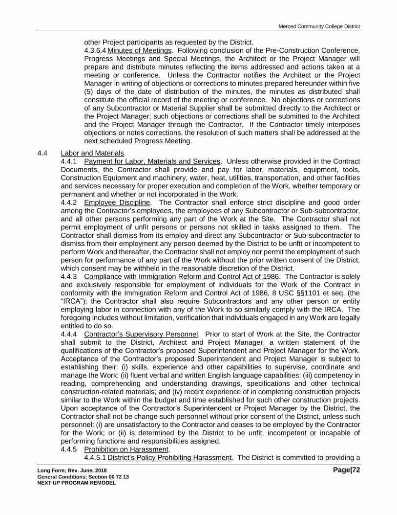
Merced Community College District
Long Form; Rev. June, 2018 Page|72 General Conditions; Section 00 72 13 NEXT UP PROGRAM REMODEL
other Project participants as requested by the District. 4.3.6.4 Minutes of Meetings. Following conclusion of the Pre-Construction Conference, Progress Meetings and Special Meetings, the Architect or the Project Manager will prepare and distribute minutes reflecting the items addressed and actions taken at a meeting or conference. Unless the Contractor notifies the Architect or the Project Manager in writing of objections or corrections to minutes prepared hereunder within five (5) days of the date of distribution of the minutes, the minutes as distributed shall constitute the official record of the meeting or conference. No objections or corrections of any Subcontractor or Material Supplier shall be submitted directly to the Architect or the Project Manager; such objections or corrections shall be submitted to the Architect and the Project Manager through the Contractor. If the Contractor timely interposes objections or notes corrections, the resolution of such matters shall be addressed at the next scheduled Progress Meeting.
4.4 Labor and Materials. 4.4.1 Payment for Labor, Materials and Services. Unless otherwise provided in the Contract Documents, the Contractor shall provide and pay for labor, materials, equipment, tools, Construction Equipment and machinery, water, heat, utilities, transportation, and other facilities and services necessary for proper execution and completion of the Work, whether temporary or permanent and whether or not incorporated in the Work. 4.4.2 Employee Discipline. The Contractor shall enforce strict discipline and good order among the Contractor’s employees, the employees of any Subcontractor or Sub-subcontractor, and all other persons performing any part of the Work at the Site. The Contractor shall not permit employment of unfit persons or persons not skilled in tasks assigned to them. The Contractor shall dismiss from its employ and direct any Subcontractor or Sub-subcontractor to dismiss from their employment any person deemed by the District to be unfit or incompetent to perform Work and thereafter, the Contractor shall not employ nor permit the employment of such person for performance of any part of the Work without the prior written consent of the District, which consent may be withheld in the reasonable discretion of the District. 4.4.3 Compliance with Immigration Reform and Control Act of 1986. The Contractor is solely and exclusively responsible for employment of individuals for the Work of the Contract in conformity with the Immigration Reform and Control Act of 1986, 8 USC §§1101 et seq. (the “IRCA”); the Contractor shall also require Subcontractors and any other person or entity employing labor in connection with any of the Work to so similarly comply with the IRCA. The foregoing includes without limitation, verification that individuals engaged in any Work are legally entitled to do so. 4.4.4 Contractor’s Supervisory Personnel. Prior to start of Work at the Site, the Contractor shall submit to the District, Architect and Project Manager, a written statement of the qualifications of the Contractor’s proposed Superintendent and Project Manager for the Work. Acceptance of the Contractor’s proposed Superintendent and Project Manager is subject to establishing their: (i) skills, experience and other capabilities to supervise, coordinate and manage the Work; (ii) fluent verbal and written English language capabilities; (iii) competency in reading, comprehending and understanding drawings, specifications and other technical construction-related materials; and (iv) recent experience of in completing construction projects similar to the Work within the budget and time established for such other construction projects. Upon acceptance of the Contractor’s Superintendent or Project Manager by the District, the Contractor shall not be change such personnel without prior consent of the District, unless such personnel: (i) are unsatisfactory to the Contractor and ceases to be employed by the Contractor for the Work; or (ii) is determined by the District to be unfit, incompetent or incapable of performing functions and responsibilities assigned. 4.4.5 Prohibition on Harassment.
4.4.5.1 District’s Policy Prohibiting Harassment. The District is committed to providing a
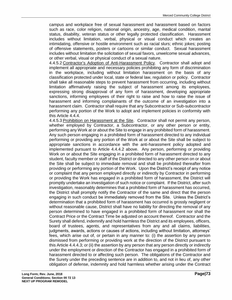
Merced Community College District
Long Form; Rev. June, 2018 Page|73 General Conditions; Section 00 72 13 NEXT UP PROGRAM REMODEL
campus and workplace free of sexual harassment and harassment based on factors such as race, color religion, national origin, ancestry, age, medical condition, marital status, disability, veteran status or other legally protected classification. Harassment includes without limitation, verbal, physical or visual conduct which creates an intimidating, offensive or hostile environment such as racial slurs; ethnic jokes; posting of offensive statements, posters or cartoons or similar conduct. Sexual harassment includes without limitation the solicitation of sexual favors, unwelcome sexual advances, or other verbal, visual or physical conduct of a sexual nature. 4.4.5.2 Contractor’s Adoption of Anti-Harassment Policy. Contractor shall adopt and implement all appropriate and necessary policies prohibiting any form of discrimination in the workplace, including without limitation harassment on the basis of any classification protected under local, state or federal law, regulation or policy. Contractor shall take all reasonable steps to prevent harassment from occurring, including without limitation affirmatively raising the subject of harassment among its employees, expressing strong disapproval of any form of harassment, developing appropriate sanctions, informing employees of their right to raise and how to raise the issue of harassment and informing complainants of the outcome of an investigation into a harassment claim. Contractor shall require that any Subcontractor or Sub-subcontractor performing any portion of the Work to adopt and implement policies in conformity with this Article 4.4.4. 4.4.5.3 Prohibition on Harassment at the Site. Contractor shall not permit any person, whether employed by Contractor, a Subcontractor, or any other person or entity, performing any Work at or about the Site to engage in any prohibited form of harassment. Any such person engaging in a prohibited form of harassment directed to any individual performing or providing any portion of the Work at or about the Site shall be subject to appropriate sanctions in accordance with the anti-harassment policy adopted and implemented pursuant to Article 4.4.4.2 above. Any person, performing or providing Work on or about the Site engaging in a prohibited form of harassment directed to any student, faculty member or staff of the District or directed to any other person on or about the Site shall be subject to immediate removal and shall be prohibited thereafter from providing or performing any portion of the Work. Upon the District’s receipt of any notice or complaint that any person employed directly or indirectly by Contractor in performing or providing the Work has engaged in a prohibited form of harassment, the District will promptly undertake an investigation of such notice or complaint. If the District, after such investigation, reasonably determines that a prohibited form of harassment has occurred, the District shall promptly notify the Contractor of the same and direct that the person engaging in such conduct be immediately removed from the Site. Unless the District’s determination that a prohibited form of harassment has occurred is grossly negligent or without reasonable cause, District shall have no liability for directing the removal of any person determined to have engaged in a prohibited form of harassment nor shall the Contract Price or the Contract Time be adjusted on account thereof. Contractor and the Surety shall defend, indemnify and hold harmless the District and its employees, officers, board of trustees, agents, and representatives from any and all claims, liabilities, judgments, awards, actions or causes of actions, including without limitation, attorneys’ fees, which arise out of, or pertain in any manner to: (i) the assertion by any person dismissed from performing or providing work at the direction of the District pursuant to this Article 4.4.4.3; or (ii) the assertion by any person that any person directly or indirectly under the employment or direction of the Contractor has engaged in a prohibited form of harassment directed to or affecting such person. The obligations of the Contractor and the Surety under the preceding sentence are in addition to, and not in lieu of, any other obligation of defense, indemnity and hold harmless whether arising under the Contract
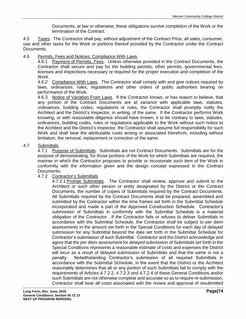
Merced Community College District
Long Form; Rev. June, 2018 Page|74 General Conditions; Section 00 72 13 NEXT UP PROGRAM REMODEL
Documents, at law or otherwise; these obligations survive completion of the Work or the termination of the Contract.
4.5 Taxes. The Contractor shall pay, without adjustment of the Contract Price, all sales, consumer, use and other taxes for the Work or portions thereof provided by the Contractor under the Contract Documents.
4.6 Permits, Fees and Notices; Compliance With Laws. 4.6.1 Payment of Permits, Fees. Unless otherwise provided in the Contract Documents, the Contractor shall secure and pay for the building permits, other permits, governmental fees, licenses and inspections necessary or required for the proper execution and completion of the Work. 4.6.2 Compliance With Laws. The Contractor shall comply with and give notices required by laws, ordinances, rules, regulations and other orders of public authorities bearing on performance of the Work. 4.6.3 Notice of Variation From Laws. If the Contractor knows, or has reason to believe, that any portion of the Contract Documents are at variance with applicable laws, statutes, ordinances, building codes, regulations or rules, the Contractor shall promptly notify the Architect and the District’s Inspector, in writing, of the same. If the Contractor performs Work knowing, or with reasonable diligence should have known, it to be contrary to laws, statutes, ordinances, building codes, rules or regulations applicable to the Work without such notice to the Architect and the District’s Inspector, the Contractor shall assume full responsibility for such Work and shall bear the attributable costs arising or associated therefrom, including without limitation, the removal, replacement or correction of the same.
4.7 Submittals. 4.7.1 Purpose of Submittals. Submittals are not Contract Documents. Submittals are for the purpose of demonstrating, for those portions of the Work for which Submittals are required, the manner in which the Contractor proposes to provide or incorporate such item of the Work in conformity with the information given and the design concept expressed in the Contract Documents. 4.7.2 Contractor’s Submittals.
4.7.2.1 Prompt Submittals. The Contractor shall review, approve and submit to the Architect or such other person or entity designated by the District or the Contract Documents, the number of copies of Submittals required by the Contract Documents. All Submittals required by the Contract Documents shall be prepared, assembled and submitted by the Contractor within the time frames set forth in the Submittal Schedule incorporated and made a part of the Approved Construction Schedule. Contractor’s submission of Submittals in conformity with the Submittal Schedule is a material obligation of the Contractor. If the Contractor fails or refuses to deliver Submittals in accordance with the Submittal Schedule, the Contractor shall be subject to per diem assessments in the amount set forth in the Special Conditions for each day of delayed submission for any Submittal beyond the date set forth in the Submittal Schedule for Contractor’s submission of such Submittal. Contractor and the District acknowledge and agree that the per diem assessment for delayed submission of Submittals set forth in the Special Conditions represents a reasonable estimate of costs and expenses the District will incur as a result of delayed submission of Submittals and that the same is not a penalty. Notwithstanding Contractor’s submission of all required Submittals in accordance with the Submittal Schedule, in the event that the District or the Architect reasonably determines that all or any portion of such Submittals fail to comply with the requirements of Articles 4.7.2.2, 4.7.2.3 and 4.7.2.4 of these General Conditions and/or such Submittals are not otherwise complete and accurate so as to require re-submission, Contractor shall bear all costs associated with the review and approval of resubmitted
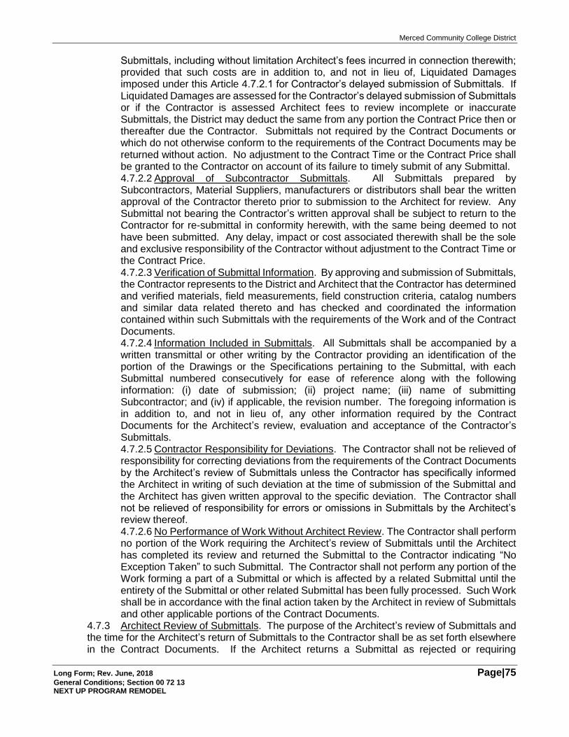
Merced Community College District
Long Form; Rev. June, 2018 Page|75 General Conditions; Section 00 72 13 NEXT UP PROGRAM REMODEL
Submittals, including without limitation Architect’s fees incurred in connection therewith; provided that such costs are in addition to, and not in lieu of, Liquidated Damages imposed under this Article 4.7.2.1 for Contractor’s delayed submission of Submittals. If Liquidated Damages are assessed for the Contractor’s delayed submission of Submittals or if the Contractor is assessed Architect fees to review incomplete or inaccurate Submittals, the District may deduct the same from any portion the Contract Price then or thereafter due the Contractor. Submittals not required by the Contract Documents or which do not otherwise conform to the requirements of the Contract Documents may be returned without action. No adjustment to the Contract Time or the Contract Price shall be granted to the Contractor on account of its failure to timely submit of any Submittal. 4.7.2.2 Approval of Subcontractor Submittals. All Submittals prepared by Subcontractors, Material Suppliers, manufacturers or distributors shall bear the written approval of the Contractor thereto prior to submission to the Architect for review. Any Submittal not bearing the Contractor’s written approval shall be subject to return to the Contractor for re-submittal in conformity herewith, with the same being deemed to not have been submitted. Any delay, impact or cost associated therewith shall be the sole and exclusive responsibility of the Contractor without adjustment to the Contract Time or the Contract Price. 4.7.2.3 Verification of Submittal Information. By approving and submission of Submittals, the Contractor represents to the District and Architect that the Contractor has determined and verified materials, field measurements, field construction criteria, catalog numbers and similar data related thereto and has checked and coordinated the information contained within such Submittals with the requirements of the Work and of the Contract Documents. 4.7.2.4 Information Included in Submittals. All Submittals shall be accompanied by a written transmittal or other writing by the Contractor providing an identification of the portion of the Drawings or the Specifications pertaining to the Submittal, with each Submittal numbered consecutively for ease of reference along with the following information: (i) date of submission; (ii) project name; (iii) name of submitting Subcontractor; and (iv) if applicable, the revision number. The foregoing information is in addition to, and not in lieu of, any other information required by the Contract Documents for the Architect’s review, evaluation and acceptance of the Contractor’s Submittals. 4.7.2.5 Contractor Responsibility for Deviations. The Contractor shall not be relieved of responsibility for correcting deviations from the requirements of the Contract Documents by the Architect’s review of Submittals unless the Contractor has specifically informed the Architect in writing of such deviation at the time of submission of the Submittal and the Architect has given written approval to the specific deviation. The Contractor shall not be relieved of responsibility for errors or omissions in Submittals by the Architect’s review thereof. 4.7.2.6 No Performance of Work Without Architect Review. The Contractor shall perform no portion of the Work requiring the Architect’s review of Submittals until the Architect has completed its review and returned the Submittal to the Contractor indicating “No Exception Taken” to such Submittal. The Contractor shall not perform any portion of the Work forming a part of a Submittal or which is affected by a related Submittal until the entirety of the Submittal or other related Submittal has been fully processed. Such Work shall be in accordance with the final action taken by the Architect in review of Submittals and other applicable portions of the Contract Documents.
4.7.3 Architect Review of Submittals. The purpose of the Architect’s review of Submittals and the time for the Architect’s return of Submittals to the Contractor shall be as set forth elsewhere in the Contract Documents. If the Architect returns a Submittal as rejected or requiring
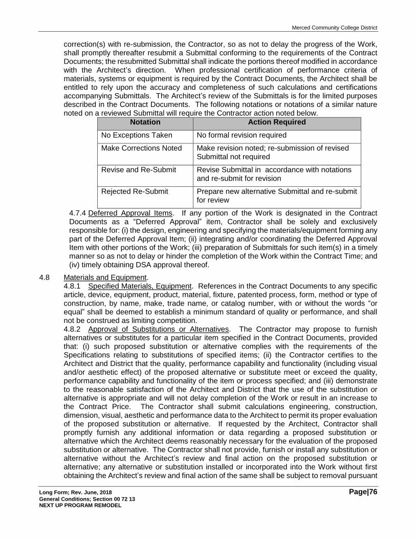
Merced Community College District
Long Form; Rev. June, 2018 Page|76 General Conditions; Section 00 72 13 NEXT UP PROGRAM REMODEL
correction(s) with re-submission, the Contractor, so as not to delay the progress of the Work, shall promptly thereafter resubmit a Submittal conforming to the requirements of the Contract Documents; the resubmitted Submittal shall indicate the portions thereof modified in accordance with the Architect’s direction. When professional certification of performance criteria of materials, systems or equipment is required by the Contract Documents, the Architect shall be entitled to rely upon the accuracy and completeness of such calculations and certifications accompanying Submittals. The Architect’s review of the Submittals is for the limited purposes described in the Contract Documents. The following notations or notations of a similar nature noted on a reviewed Submittal will require the Contractor action noted below.
Notation Action Required
No Exceptions Taken No formal revision required
Make Corrections Noted Make revision noted; re-submission of revised Submittal not required
Revise and Re-Submit Revise Submittal in accordance with notations and re-submit for revision
Rejected Re-Submit Prepare new alternative Submittal and re-submit for review
4.7.4 Deferred Approval Items. If any portion of the Work is designated in the Contract Documents as a “Deferred Approval” item, Contractor shall be solely and exclusively responsible for: (i) the design, engineering and specifying the materials/equipment forming any part of the Deferred Approval Item; (ii) integrating and/or coordinating the Deferred Approval Item with other portions of the Work; (iii) preparation of Submittals for such item(s) in a timely manner so as not to delay or hinder the completion of the Work within the Contract Time; and (iv) timely obtaining DSA approval thereof.
4.8 Materials and Equipment. 4.8.1 Specified Materials, Equipment. References in the Contract Documents to any specific article, device, equipment, product, material, fixture, patented process, form, method or type of construction, by name, make, trade name, or catalog number, with or without the words “or equal” shall be deemed to establish a minimum standard of quality or performance, and shall not be construed as limiting competition. 4.8.2 Approval of Substitutions or Alternatives. The Contractor may propose to furnish alternatives or substitutes for a particular item specified in the Contract Documents, provided that: (i) such proposed substitution or alternative complies with the requirements of the Specifications relating to substitutions of specified items; (ii) the Contractor certifies to the Architect and District that the quality, performance capability and functionality (including visual and/or aesthetic effect) of the proposed alternative or substitute meet or exceed the quality, performance capability and functionality of the item or process specified; and (iii) demonstrate to the reasonable satisfaction of the Architect and District that the use of the substitution or alternative is appropriate and will not delay completion of the Work or result in an increase to the Contract Price. The Contractor shall submit calculations engineering, construction, dimension, visual, aesthetic and performance data to the Architect to permit its proper evaluation of the proposed substitution or alternative. If requested by the Architect, Contractor shall promptly furnish any additional information or data regarding a proposed substitution or alternative which the Architect deems reasonably necessary for the evaluation of the proposed substitution or alternative. The Contractor shall not provide, furnish or install any substitution or alternative without the Architect’s review and final action on the proposed substitution or alternative; any alternative or substitution installed or incorporated into the Work without first obtaining the Architect’s review and final action of the same shall be subject to removal pursuant
Merced Community College District
Long Form; Rev. June, 2018 Page|77 General Conditions; Section 00 72 13 NEXT UP PROGRAM REMODEL
to Article 12 hereof. The Architect’s decision evaluating the Contractor’s proposed substitutions or alternatives shall be final. Neither the Contract Time nor the Contract Price shall be increased on account of any substitution or alternative proposed by the Contractor and which is accepted by the Architect; provided, however, that in the event a substitution or alternative accepted by the Architect and purchase, fabrication and/or installation or such accepted substitution or alternative shall be less expensive than the originally specified item, the Contract Price shall be reduced by the actual cost savings realized by the Contractor’s furnishing and/or installation of such approved substitution or alternative. The Contractor shall be solely responsible for all costs and fees incurred by the District to review a proposed substitution or alternative, including without limitation fees of the Architect, and/or governmental agencies to review and/or approve any proposed substitution or alternative. The Contractor shall be solely responsible for any increase in the cost of any accepted substitution or alternative or any Work affected by such alternative or substitution. The foregoing notwithstanding, all requests for the Architect’s review and approval of any proposed substitution or alternative and all engineering, construction, dimension and performance data substantiating the equivalency of the proposed substitution or alternative shall be submitted by Contractor not later than thirty-five (35) days following the date of the District’s award of the Contract to Contractor by action of the District’s Board of Trustees; any request for approval of proposed alternatives or substitutions submitted thereafter may be rejected summarily. The foregoing process and time limits shall apply to any proposed substitution or alternative regardless of whether the substitute or alternate item is to be provided, furnished or installed by Contractor, any Subcontractor, any Sub-Subcontractor, Material Supplier or Manufacturer. 4.8.3 Placement of Material and Equipment Orders. Contractor shall, after award of the Contract, promptly and timely place all orders for materials and/or equipment necessary for completion of the Work so that delivery of the same shall be made without delay or interruption to the timely completion of the Work. Contractor shall require that any Subcontractor similarly place orders for all materials and/or equipment to be furnished by any such Subcontractor in a prompt and timely manner so that delivery of the same shall be made without delay or interruption to the timely completion of the Work. Upon request of the District, Project Manager or the Architect, the Contractor shall furnish reasonably satisfactory written evidence of the placement of orders for materials and/or equipment necessary for completion of the Work, including without limitation, orders for materials and/or equipment to be provided, furnished or installed by any Subcontractor. 4.8.4 District’s Right to Place Orders for Materials and/or Equipment. Notwithstanding any other provision of the Contract Documents, if the Contractor shall, upon request of the District, Project Manager or the Architect, fails or refuses, for any reason, to provide reasonably satisfactory written evidence of the placement of orders for materials and/or equipment necessary for completion of the Work, or should the District determine, in its sole and reasonable discretion, that any orders for materials and/or equipment have not been placed in a manner so that such materials and/or equipment will be delivered to the Site so the Work can be completed without delay or interruption, the District shall have the right, but not the obligation, to place such orders on behalf of the Contractor. If the District exercises the right to place orders for materials and/or equipment pursuant to the foregoing, the District’s conduct shall not be deemed to be an exercise, by the District, of any control over the means, methods, techniques, sequences or procedures for completion of the Work, all of which remain the responsibility and obligation of the Contractor. Notwithstanding the right of the District to place orders for materials and/or equipment pursuant to the foregoing, the election of the District to exercise, or not to exercise, such right shall not relieve the Contractor from any of Contractor’s obligations under the Contract Documents, including without limitation, completion of the Work within the Contract Time and for the Contract Price. If the District exercises the right hereunder to place orders for materials and/or equipment on behalf of Contractor pursuant to the foregoing, Contractor shall reimburse
Merced Community College District
Long Form; Rev. June, 2018 Page|78 General Conditions; Section 00 72 13 NEXT UP PROGRAM REMODEL
the District for all costs and fees incurred by the District in placing such orders; such costs and fees may be deducted by the District from the Contract Price then or thereafter due the Contractor. 4.8.5 Contractor and Subcontractor Communication. All written communications between the Contractor and any Subcontractor, Material Supplier or others directly or indirectly engaged by the Contractor to perform or provide any portion of the Work shall be available to the District, the Project Manager and the Architect for review, inspection and reproduction as may be requested from time to time. The foregoing is a material obligation of the Contractor hereunder.
4.9 Safety. 4.9.1 Safety Programs. The Contractor shall be solely responsible for initiating, maintaining and supervising all safety programs required by applicable law, ordinance, regulation or governmental orders in connection with the performance of the Contract, or otherwise required by the type or nature of the Work. The Contractor’s safety program shall include all actions and programs necessary for compliance with California or federally statutorily mandated workplace safety programs, including without limitation, compliance with the California Drug Free Workplace Act of 1990 (California Government Code §§8350 et seq.). Without limiting or relieving the Contractor of its obligations hereunder, the Contractor shall require that its Subcontractors similarly initiate and maintain all appropriate or required safety programs. 4.9.2 Contractor Safety Plan. Prior to commencement of Work at the Site, the Contractor shall submit to the District and the Project Manager, if any, the Contractor’s Safety Plan for the Work for review and acceptance by the District. Acceptance by the District is subject to the Safety Plan conforming to requirements of the Laws, conditions at or about the Site and the nature of the Work. The Contractor shall modify its Safety Plan as necessary to obtain the District’s acceptance thereof. Notwithstanding the District’s acceptance of the Contractor’s Safety Plan, the Contractor shall remain solely responsible for implementing the Safety Plan and implementing measures as necessary to maintain safety of persons and property at and about the Site. The District’s acceptance of the Contractor’s Safety Plan shall not limit, restrict or otherwise modify the Contractor’s obligations relating to safety at or about the Site in accordance with the Contract Documents and the Laws. 4.9.3 Safety Precautions. The Contractor shall be solely responsible for initiating and maintaining reasonable precautions for safety of, and shall provide reasonable protection to prevent damage, injury or loss to: (i) employees on the Work and other persons who may be affected thereby; (ii) the Work and materials and equipment to be incorporated therein, whether in storage on or off the Site, under care, custody or control of the Contractor or Subcontractors; and (iii) other property or items at the Site, or adjacent thereto, such as trees, shrubs, lawns, walks, pavements, roadways, structures and utilities not designated for removal, relocation or replacement. 4.9.4 Safety Signs, Barricades. The Contractor shall erect and maintain, as required by existing conditions and conditions resulting from performance of the Contract, reasonable safeguards for safety and protection of property and persons, including, without limitation, posting danger signs and other warnings against hazards, barricades, promulgating safety regulations and notifying owners and users of adjacent sites and utilities. 4.9.5 Safety Notices. The Contractor shall give or post all safety notices required by the Laws and comply with the Laws bearing on safety of persons or property or their protection from damage, injury or loss. 4.9.6 Safety Coordinator. The Contractor shall designate a responsible member of the Contractor’s organization at the Site whose duty shall be the prevention of accidents and the implementation and maintenance safety precautions and programs. This person shall be the Contractor’s superintendent unless otherwise designated by the Contractor in writing to the Project Manager, District’s Inspector and the Architect. 4.9.7 Emergencies. In an emergency affecting safety of persons or property, the Contractor
Merced Community College District
Long Form; Rev. June, 2018 Page|79 General Conditions; Section 00 72 13 NEXT UP PROGRAM REMODEL
shall act, to prevent threatened damage, injury or loss. 4.9.8 Hazardous Materials.
4.9.8.1 General. If the Contractor, any Subcontractor or anyone employed directly or indirectly by them shall use, at the Site, or incorporate into the Work, any material or substance deemed to be hazardous or toxic under any law, rule, ordinance, regulation or interpretation thereof (collectively “Hazardous Materials”), the Contractor shall comply with all Laws applicable thereto and shall exercise all necessary safety precautions relating to the use, storage or disposal thereof. 4.9.8.2 Prohibition on Use of Asbestos Construction Building Materials (“ACBMs”). Notwithstanding any provision of the Drawings or the Specifications to the contrary, it is the intent of the District that ACBMs not be used or incorporated into any portion of the Work. In the event that any portion of the Work depicted in the Drawings or the Specifications shall require materials or products which the Contractor knows, or should have known with reasonably diligent investigation, to contain ACBMs, Contractor shall promptly notify the Architect and the District’s Inspector of the same so that an appropriate alternative can be made in a timely manner so as not to delay the progress of the Work. Contractor warrants to the District that there are no materials or products used or incorporated into the Work which contain ACBMs. Whether before or after completion of the Work, if it is discovered that any product or material forming a part of the Work or incorporated into the Work contains ACBMs, the Contractor shall at its sole cost and expense remove such product or material in accordance with any laws, rules, procedures and regulations applicable to the handling, removal and disposal of ACBMs and to replace such product or material with non-ACBM products or materials and to return the affected portion(s) of the Work to the finish condition depicted in the Drawings and Specifications relating to such portion(s) of the Work. Contractor’s obligations under the preceding sentence shall survive the termination of the Contract, the warranty period provided under the Contract Documents, the Contractor’s completion of the Work or the District’s acceptance of the Work. If the Contractor fails or refuses, for any reason, to commence the removal and replacement of any material or product containing ACBMs forming a part of, or incorporated into the Work, within ten (10) days of the date of the District’s written notice to the Contractor of the existence of ACBM materials or products in the Work, the District may thereafter proceed to cause the removal and replacement of such materials or products in any manner which the District determines to be reasonably necessary and appropriate; all costs, expenses and fees, including without limitation fees and costs of consultants and attorneys, incurred by the District in connection with such removal and replacement shall be the responsibility of the Contractor and the Surety. 4.9.8.3 Disposal of Hazardous Materials. Contractor shall be solely and exclusively responsible for the disposal of any Hazardous Materials on or about the Site. The Contractor’s obligations hereunder shall include without limitation, the transportation and disposal of any Hazardous Materials in strict conformity with the Laws.
4.10 Maintenance of Documents. 4.10.1 Documents at Site. The Contractor shall maintain at the Site: (i) one record copy of the Drawings, Specifications and all addenda thereto; (ii) Change Orders approved by the District and all other modifications to the Contract Documents; (iii) Submittals reviewed by the Architect; (iv) Record Drawings; (v) Material Safety Data Sheets (“MSDS”) accompanying any materials, equipment or products delivered or stored at the Site or incorporated into the Work; and (vi) all building and other codes or regulations applicable to the Work, including without limitation, Title 24, Part 2 of the California Code of Regulations. During performance of the Work, all documents maintained by Contractor at the Site shall be available to the District, the Project Manager, the Architect, the District’s Inspector and DSA for review, inspection or reproduction. Upon
Merced Community College District
Long Form; Rev. June, 2018 Page|80 General Conditions; Section 00 72 13 NEXT UP PROGRAM REMODEL
completion of the Work, all documents maintained at the Site by the Contractor pursuant to the foregoing shall be assembled and transmitted to the Architect for delivery to the District. 4.10.2 Maintenance of Record Drawings. During its performance of the Work, the Contractor shall maintain Record Drawings consisting of a set of the Drawings which are marked to indicate all field changes made to adapt the Work depicted in the Drawings to field conditions, changes resulting from Change Orders and all concealed or buried installations, including without limitation, piping, conduit and utility services. All buried or concealed items of Work shall be completely and accurately marked and located on the Record Drawings. The Record Drawings shall be clean and all changes, corrections and dimensions shall be marked in a neat and legible manner in a contrasting color. Record Drawings relating to the Structural, Mechanical, Electrical and Plumbing portions of the Work shall indicate without limitation, circuiting, wiring sizes, equipment/member sizing and shall depict the entirety of the as built conditions of such portions of the Work. The Record Drawings shall be continuously maintained by the Contractor during the performance of the Work. At any time during the Contractor’s performance of the Work, upon the request of the District, the District’s Inspector or the Architect, the Contractor shall make the Record Drawings maintained here under available for the District’s review and inspection. The District’s review and inspection of the Record Drawings during the Contractor’s performance of the Work shall be only for the purpose of generally verifying that Contractor is continuously maintaining the Record Drawings in a complete and accurate manner; any such inspection or review shall not be deemed to be the District’s approval or verification of the completeness or accuracy thereof. The failure or refusal of the Contractor to continuously maintain complete and accurate Record Drawings or to make available the Record Drawings for inspection and review by the District may be deemed by the District to be Contractor’s default of a material obligation hereunder. Without waiving, restricting or limiting any other right or remedy of the District for the Contractor’s failure or refusal to continuously maintain the Record Drawings, the District may, upon reasonably determining that the Contractor has not, or is not, continuously maintaining the Record Drawings in a complete and accurate manner, take appropriate action to cause the continuous maintenance of complete and accurate Record Drawings, in which event all fees and costs incurred or associated with such action shall be charged to the Contractor and the District may deduct the amount of such fees and costs from any portion of the Contract Price then or thereafter due the Contractor. In accordance with Article 8.4.2 of these General Conditions, prior to receipt of the Final Payment, Contractor shall deliver the Record Drawings to the Architect.
4.11 Use of Site. The Contractor shall confine operations at the Site to areas permitted by the Laws, subject to any restrictions or limitations set forth in the Contract Documents. The Contractor shall not unreasonably encumber the Site or adjoining areas with materials or equipment. The Contractor shall be solely responsible for providing security at the Site with all such costs included in the Contract Price. The District shall at all times have access to the Site.
4.12 Clean-Up. The Contractor shall at all times keep the Site and all adjoining areas free from the accumulation of any waste material or rubbish caused or generated by performance of the Work. Without limiting the generality of the foregoing, Contractor shall maintain the Site in a “rake-clean” standard on a daily basis. If the Work includes painting and/or the installation of floor covering, before any painting operations or the installation of any flooring covering, the area and adjoining areas of the Site where paint is to be applied or floor covering is to be installed shall be in a “broom-clean” condition. Prior to completion of the Work, Contractor shall remove from the Site all rubbish, waste materials, excess excavated materials, tools, Construction Equipment, machinery, surplus materials and any other items which are not the property of the District under the Contract Documents. Upon completion of the Work, the Site and all adjoining areas shall be left by the Contractor in a neat and broom clean condition satisfactory to District. The District’s Inspector or Project Manager shall be authorized to direct the Contractor’s clean-up obligations hereunder. If the Contractor fails to clean up as provided for in the
Merced Community College District
Long Form; Rev. June, 2018 Page|81 General Conditions; Section 00 72 13 NEXT UP PROGRAM REMODEL
Contract Documents, the District may do so, and all costs incurred in connection therewith shall be charged to the Contractor; the District may deduct such costs from any portion of the Contract Price then or thereafter due the Contractor.
4.13 Access to the Work. The Contractor shall provide DSA, the District, the Project Manager, the District’s Inspector and the Architect access to the Work, whether in place, preparation and progress and wherever located.
4.14 Facilities and Information for the District’s Inspector. 4.14.1 Information to District’s Inspector. The Contractor shall furnish the District’s Inspector access to the Work for obtaining such information as may be necessary to keep the District’s Inspector fully informed respecting the progress, quality and character of the Work and materials, equipment or other items incorporated therein. 4.14.2 Facilities for District’s Inspector. Facilities, services or other items to be provided by the Contractor for use by the District’s Inspector, if any, shall be as set forth in the Special Conditions. If any such facilities, services or other items are designated in the Special Conditions and the Contractor fails or refuses to provide the same, the District may furnish such facilities, services or other items, with the costs, fees or expenses incurred to furnish the same being deducted from the Contract Price.
4.15 Patents and Royalties. The Contractor and the Surety shall defend, indemnify and hold harmless the District and its agents, employees and officers from any claim, demand or legal proceeding arising out of or pertaining, in any manner, to any actual or claimed infringement of patent rights in connection with performance of the Work.
4.16 Cutting and Patching. The Contractor is responsible for cutting, fitting or patching required to complete the Work or to make the component parts thereof fit together properly. The Contractor shall not damage or endanger any portion of the Work, or the fully or partially completed construction of the District or separate contractors by cutting, patching, excavation or other alteration. The Contractor shall not cut, patch or otherwise alter the construction by the District or separate contractor without the prior written consent of the District or separate contractor thereto, which consent shall not be unreasonably withheld. The Contractor shall not unreasonably withhold consent to the request of the District or separate contractor to cut, patch or otherwise alter the Work.
4.17 Encountering of Hazardous Materials. If the Contractor encounters Hazardous Materials at the Site which have not been rendered harmless or for which there is no provision in the Contract Documents for containment, removal, abatement or handling of such Hazardous Materials, the Contractor shall immediately stop the Work in the affected area, but shall diligently proceed with the Work in all other unaffected areas. Upon encountering such Hazardous Materials, the Contractor shall immediately notify the District’s Inspector and the Architect, in writing, of such condition. The Contractor shall proceed with the Work in such affected area only after such Hazardous Materials have been rendered harmless, contained, removed or abated. If such Hazardous Materials are encountered, the Contractor shall be entitled to an adjustment of the Contract Time to the extent that the Work is stopped and Substantial Completion of the Work is affected thereby. In no event shall there be an adjustment to the Contract Price solely on account of the Contractor encountering such Hazardous Materials.
4.18 Wage Rates; Employment of Labor. 4.18.1 Determination of Prevailing Rates. Pursuant to the provisions of Division 2, Part 7, Chapter 1, Article 2 of the California Labor Code at §§1770 et seq., the District has obtained from the Director of the Department of Industrial Relations the general prevailing rate of per diem wages and the prevailing rate for holiday and overtime work in the locality in which the Work is to be performed. Holidays shall be as defined in the collective bargaining agreement applicable to each particular craft, classification or type of worker employed under the Contract. Per diem wages include employer payments for health and welfare, pensions, vacation, travel time and
Merced Community College District
Long Form; Rev. June, 2018 Page|82 General Conditions; Section 00 72 13 NEXT UP PROGRAM REMODEL
subsistence pay as provided in California Labor Code §1773.8, apprenticeship or other training programs authorized by California Labor Code §3093, and similar purposes when the term “per diem wages” is used herein. Holiday and overtime work, when permitted by law, shall be paid for at the rate of at least one and one-half (1½) times the above specified rate of per diem wages, unless otherwise specified. The Contractor shall post, at appropriate and conspicuous locations on the Site, a schedule showing all determined general prevailing wage rates. 4.18.2 Payment of Prevailing Rates. There shall be paid each worker of the engaged in the Work, not less than the general prevailing wage rate for the classification of Work performed, regardless of any contractual relationship which may be alleged to exist between the Contractor or any Subcontractor and such worker. 4.18.3 Prevailing Rate Penalty. The Contractor shall, as a penalty, forfeit not more than Two Hundred Dollars ($200.00) to the District for each calendar day or portion thereof, for each worker paid less than the prevailing rates for such work or craft in which such worker is employed for the Work by the Contractor or by any Subcontractor, of any tier, in connection with the Work. The amount of the penalty for failure to pay applicable prevailing wage rates shall be determined and assessed in accordance with the standards established pursuant to Labor Code §1775(a)(2). The amount of the penalty shall be determined based on consideration of both of the following: (i) whether the failure of the Contractor or Subcontractor to pay the correct rate of per diem wages was a good faith mistake and, if so, the error was promptly and voluntarily corrected when brought to the attention of the Contractor or Subcontractor; and (ii) whether the Contractor or Subcontractor has a prior record of failing to meet its prevailing wage obligations. The penalty may not be less than forty dollars ($40) for each calendar day, or portion thereof, for each worker paid less than the prevailing wage rate, unless the failure of the Contractor or Subcontractor to pay the correct rate of per diem wages was a good faith mistake and, if so, the error was promptly and voluntarily corrected when brought to the attention of the contractor or subcontractor. The penalty may not be less than eighty dollars ($80) for each calendar day, or portion thereof, for each worker paid less than the prevailing wage rate, if the Contractor or Subcontractor has been assessed penalties within the previous three years for failing to meet its prevailing wage obligations on a separate contract, unless those penalties were subsequently withdrawn or overturned. The penalty may not be less than one hundred twenty dollars ($120) for each calendar day, or portion thereof, for each worker paid less than the prevailing wage rate, if the Labor Commissioner determines that the violation was willful, as defined in subdivision (c) of Section 1777.1. When the penalty amount due hereunder is collected from the Contractor or Subcontractor, any outstanding wage claim under Chapter 1 (commencing with Section 1720) of Part 7 of Division 2 against that Contractor or Subcontractor shall be satisfied before applying that amount to the penalty imposed on that Contractor or Subcontractor hereunder. The difference between prevailing wage rates and the amount paid to each worker each calendar day, or portion thereof, for which each worker paid less than the prevailing wage rate, shall be paid to each worker by the Contractor. 4.18.4 Certified Payroll Records.
4.18.4.1 Maintenance of Certified Payroll Records. Pursuant to California Labor Code §1776, the Contractor and each Subcontractor, of any tier, shall keep an accurate payroll record, showing the name, address, social security number, work classification, straight time and overtime hours worked each day and week, and the actual per diem wages paid to each person employed for the Work. 4.18.4.2 Submittal of Certified Payroll Records to Labor Commissioner. The Contractor and each Subcontractor shall submit their respective Certified Payroll Records to the Labor Commissioner on forms, in the manner and within the times prescribed by the Labor Commissioner. 4.18.4.3 Inspection of Certified Payroll Records. The Certified Payroll Records of the Contractor and Subcontractors shall be available for inspection at all reasonable
Merced Community College District
Long Form; Rev. June, 2018 Page|83 General Conditions; Section 00 72 13 NEXT UP PROGRAM REMODEL
hours at the principal office of the Contractor on the following basis: (i) a certified copy of an employee’s payroll record shall be made available for inspection or furnished to such employee or his/her authorized representative on request; (ii) a certified copy of all payroll records shall be made available for inspection or furnished upon request to the District, the Division of Labor Standards Enforcement and the Division of Apprenticeship Standards of the Department of Industrial Relations; (iii) a certified copy of payroll records shall be made available upon request to the public for inspection or copies thereof made; provided, however, that a request by the public shall be made through either the District, the Division of Apprenticeship Standards, or the Division of Labor Standards Enforcement. If the requested Certified Payroll Records have not been provided, the requesting party shall, prior to being provided the records, reimburse the cost of preparation by the Contractor, Subcontractors and the entity through which the request was made; the public shall not be given access to such records at the principal office of the Contractor; (iv) the Contractor shall file a certified copy of the Certified Payroll Records with the entity that requested such records within ten (10) days after receipt of a written request; (v) any copy of records made available for inspection as copies and furnished upon request to the public or any public agency by the District, the Division of Apprenticeship Standards or the Division of Labor Standards Enforcement shall be marked or obliterated in such a manner as to prevent disclosure of an individual’s name, address and social security number. The name and address of the Contractor or any Subcontractor, of any tier, performing a part of the Work shall not be marked or obliterated. The Contractor shall inform the District of the location of Certified Payroll Records, including the street address, city and county and shall, within five (5) working days, provide a notice of a change or location and address. In the event of noncompliance with the requirements of this Article 4.18.4, the Contractor shall have ten (10) days in which to comply, subsequent to receipt of written notice specifying in what respects the Contractor must comply herewith. Should noncompliance still be evident after such 10-day period, the Contractor shall, as a penalty to the District, forfeit One Hundred Dollars ($100.00) for each calendar day, or portion thereof, for each worker, until strict compliance is effectuated. Upon the request of the Division of Apprenticeship Standards or the Division of Labor Standards Enforcement, such penalties shall be withheld from any portion of the Contract Price then or thereafter due the Contractor. The Contractor is solely responsible for compliance with the foregoing provisions.
4.18.5 Hours of Work. 4.18.5.1 Limits on Hours of Work. Pursuant to California Labor Code §1810, eight (8) hours of labor shall constitute a legal day’s work. Pursuant to California Labor Code §1811, the time of service of any worker employed at any time by the Contractor or by a Subcontractor, of any tier, upon the Work or upon any part of the Work, is limited and restricted to eight (8) hours during any one calendar day and forty (40) hours during any one calendar week, except as hereafter provided. Notwithstanding the foregoing provisions, Work performed by employees of Contractor or any Subcontractor, of any tier, in excess of eight (8) hours per day and forty (40) hours during any one week, shall be permitted upon compensation for all hours worked in excess of eight (8) hours per day at not less than one and one-half (12) times the basic rate of pay. 4.18.5.2 Penalty for Excess Hours. The Contractor shall pay to the District a penalty of Twenty-five Dollars ($25.00) for each worker employed on the Work by the Contractor or any Subcontractor, of any tier, for each calendar day during which such worker is required or permitted to work more than eight (8) hours in any calendar day and forty (40) hours in any one calendar week, in violation of the provisions of the California Labor Code, unless compensation to the worker so employed by the Contractor is not less than one and one-half (12) times the basic rate of pay for all hours
Merced Community College District
Long Form; Rev. June, 2018 Page|84 General Conditions; Section 00 72 13 NEXT UP PROGRAM REMODEL
worked in excess of eight (8) hours per day. 4.18.5.3 Contractor Responsibility. Any Work performed by workers necessary to be performed after regular working hours or on Sundays or other holidays shall be performed without adjustment to the Contract Price or any other additional expense to the District.
4.18.6 Apprentices. 4.18.6.1 Employment of Apprentices. Any apprentices employed to perform any of the Work shall be paid the standard wage paid to apprentices under the regulations of the craft or trade for which such apprentice is employed, and such individual shall be employed only for the work of the craft or trade to which such individual is registered. Only apprentices, as defined in California Labor Code §3077 who are in training under apprenticeship standards and written apprenticeship agreements under California Labor Code §§3070 et seq. are eligible to be employed for the Work. The employment and training of each apprentice shall be in accordance with the provisions of the apprenticeship standards and apprentice agreements under which such apprentice is training. 4.18.6.2 Apprenticeship Certificate. When the Contractor or any Subcontractor, of any tier, in performing any of the Work employs workers in any Apprenticeable Craft or Trade, the Contractor and such Subcontractor shall apply to the Joint Apprenticeship Committee administering the apprenticeship standards of the craft or trade in the area of the site of the Work for a certificate approving the Contractor or such Subcontractor under the apprenticeship standards for the employment and training of apprentices in the area or industry affected, provided, however, that the approval as established by the Joint Apprenticeship Committee or Committees shall be subject to the approval of the Administrator of Apprenticeship. The Joint Apprenticeship Committee or Committees, subsequent to approving the Contractor or Subcontractor, shall arrange for the dispatch of apprentices to the Contractor or such Subcontractor in order to comply with California Labor Code §1777.5. The Contractor and Subcontractors shall submit contract award information to the applicable Joint Apprenticeship Committee which shall include an estimate of journeyman hours to be performed under the Contract, the number of apprentices to be employed, and the approximate dates the apprentices will be employed. There shall be an affirmative duty upon the Joint Apprenticeship Committee or Committees, administering the apprenticeship standards of the crafts or trades in the area of the site of the Work, to ensure equal employment and affirmative action and apprenticeship for women and minorities. Contractors or Subcontractors shall not be required to submit individual applications for approval to local Joint Apprenticeship Committees provided they are already covered by the local apprenticeship standards. 4.18.6.3 Ratio of Apprentices to Journeymen. The ratio of Work performed by apprentices to journeymen, who shall be employed in the Work, may be the ratio stipulated in the apprenticeship standards under which the Joint Apprenticeship Committee operates, but in no case shall the ratio be less than one hour of apprentice work for each five hours of labor performed by a journeyman, except as otherwise provided in California Labor Code §1777.5. The minimum ratio for the land surveyor classification shall not be less than one apprentice for each five journeymen. Any ratio shall apply during any day or portion of a day when any journeyman, or the higher standard stipulated by the Joint Apprenticeship Committee, is employed at the site of the Work and shall be computed on the basis of the hours worked during the day by journeymen so employed, except for the land surveyor classification. The Contractor shall employ apprentices for the number of hours computed as above before the completion of the Work. The Contractor shall, however, endeavor, to the greatest extent possible, to employ apprentices during the same time period that the journeymen in the
Merced Community College District
Long Form; Rev. June, 2018 Page|85 General Conditions; Section 00 72 13 NEXT UP PROGRAM REMODEL
same craft or trade are employed at the site of the Work. Where an hourly apprenticeship ratio is not feasible for a particular craft or trade, the Division of Apprenticeship Standards, upon application of a Joint Apprenticeship Committee, may order a minimum ratio of not less than one apprentice for each five journeymen in a craft or trade classification. The Contractor or any Subcontractor covered by this Article and California Labor Code §1777.5, upon the issuance of the approval certificate, or if it has been previously approved in such craft or trade, shall employ the number of apprentices or the ratio of apprentices to journeymen stipulated in the apprenticeship standards. Upon proper showing by the Contractor that it employs apprentices in such craft or trade in the State of California on all of its contracts on an annual average of not less than one apprentice to each five journeymen, the Division of Apprenticeship Standards may grant a certificate exempting the Contractor from the 1-to-5 ratio as set forth in this Article and California Labor Code §1777.5. This Article shall not apply to contracts of general contractors, or to contracts of specialty contractors not bidding for work through a general or prime contractor, involving less than Thirty Thousand Dollars ($30,000.00) or twenty (20) working days. The term “Apprenticeable Craft or Trade,” as used herein shall mean a craft or trade determined as an Apprenticeable occupation in accordance with rules and regulations prescribed by the Apprenticeship Council. 4.18.6.4 Exemption From Ratios. The Joint Apprenticeship Committee shall have the discretion to grant a certificate, which shall be subject to the approval of the Administrator of Apprenticeship, exempting the Contractor from the 1-to-5 ratio set forth in this Article when it finds that any one of the following conditions are met: (i) unemployment for the previous three-month period in such area exceeds an average of fifteen percent (15%) or; (ii) the number of apprentices in training in such area exceeds a ratio of 1-to-5 in relation to journeymen, or; (iii) the Apprenticeable Craft or Trade is replacing at least one-thirtieth (1/30) of its journeymen annually through apprenticeship training, either on a statewide basis or on a local basis, or; (iv) if assignment of an apprentice to any Work performed under the Contract Documents would create a condition which would jeopardize such apprentice’s life or the life, safety or property of fellow employees or the public at large, or if the specific task to which the apprentice is to be assigned is of such a nature that training cannot be provided by a journeyman. When such exemptions from the 1-to-5 ratio between apprentices and journeymen are granted to an organization which represents contractors in a specific trade on a local or statewide basis, the member contractors will not be required to submit individual applications for approval to local Joint Apprenticeship Committees, provided they are already covered by the local apprenticeship standards. 4.18.6.5 Contributions to Trust Funds. The Contractor or any Subcontractor, of any tier, who, performs any of the Work by employment of journeymen or apprentices in any Apprenticeable Craft or Trade and who is not contributing to a fund or funds to administer and conduct the apprenticeship program in any such craft or trade in the area of the site of the Work, to which fund or funds other contractors in the area of the site of the Work are contributing, shall contribute to the fund or funds in each craft or trade in which it employs journeymen or apprentices in the same amount or upon the same basis and in the same manner as the other contractors do, but where the trust fund administrators are unable to accept such funds, contractors not signatory to the trust agreement shall pay a like amount to the California Apprenticeship Council. The Division of Labor Standards Enforcement is authorized to enforce the payment of such contributions to such fund(s) as set forth in California Labor Code §227. Such contributions shall not result in an increase in the Contract Price. 4.18.6.6 Contractor’s Compliance. The responsibility of compliance with this Article for all Apprenticeable Trades or Crafts is solely and exclusively that of the
Merced Community College District
Long Form; Rev. June, 2018 Page|86 General Conditions; Section 00 72 13 NEXT UP PROGRAM REMODEL
Contractor. All decisions of the Joint Apprenticeship Committee(s) under this Article are subject to the provisions of California Labor Code §3081. In the event the Contractor willfully fails to comply with the provisions of this Article and California Labor Code §1777.5, pursuant to California Labor Code §1777.7, the Contractor shall: (i) be denied the right to bid on any public works contract for a period of one (1) year from the date the determination of non-compliance is made by the Administrator of Apprenticeship; and (ii) forfeit, as a civil penalty, Fifty Dollars ($50.00) for each calendar day of noncompliance. Notwithstanding the provisions of California Labor Code §1727, upon receipt of such determination, the District shall withhold such amount from the Contract Price then due or to become due. Any such determination shall be issued after a full investigation, a fair and impartial hearing, and reasonable notice thereof in accordance with reasonable rules and procedures prescribed by the California Apprenticeship Council. Any funds withheld by the District pursuant to this Article shall be deposited in the General Fund or other similar fund of the District. The interpretation and enforcement of California Labor Code §§1777.5 and 1777.7 shall be in accordance with the rules and procedures of the California Apprenticeship Council.
4.18.7 Employment of Independent Contractors. Pursuant to California Labor Code §1021.5, Contractor shall not willingly and knowingly enter into any agreement with any person, as an independent contractor, to provide any services in connection with the Work where the services provided or to be provided requires that such person hold a valid contractors’ license issued pursuant to California Business and Professions Code §§7000 et seq. and such person does not meet the burden of proof of his/her independent contractor status pursuant to California Labor Code §2750.5. In the event that Contractor shall employ any person in violation of the foregoing, Contractor shall be subject to the civil penalties under California Labor Code §1021.5 and any other penalty provided by law. In addition to the penalties provided under California Labor Code §1021.5, Contractor’s violation of this Article 4.18.7 or the provisions of California Labor Code §1021.5 shall be deemed an event of Contractor’s default under Article 15.1 of these General Conditions. The Contractor shall require Subcontractors performing or providing any portion of the Work to adhere to and comply with the foregoing provisions.
4.19 Assignment of Antitrust Claims. Pursuant to California Government Code §4551, the Contractor and its Subcontractor(s), of any tier, hereby offers and agrees to assign to the District all rights, title and interest in and to all causes of action they may have under Section 4 of the Clayton Act, (15 U.S.C. §15) or under the Cartwright Act (California Business and Professions Code §§16700 et seq.), arising from purchases of goods, services or materials hereunder or any Subcontract. This assignment shall be made and become effective at the time the District tenders Final Payment to the Contractor, without further acknowledgment by the parties. If the District receives, either through judgment or settlement, a monetary recovery in connection with a cause of action assigned under California Government Code §§4550 et seq., the assignor thereof shall be entitled to receive reimbursement for actual legal costs incurred and may, upon demand, recover from the District any portion of the recovery, including treble damages, attributable to overcharges that were paid by the assignor but were not paid by the District as part of the Contract Price, less the expenses incurred by the District in obtaining that portion of the recovery. Upon demand in writing by the assignor, the District shall, within one year from such demand, reassign the cause of action assigned pursuant to this Article if the assignor has been or may have been injured by the violation of law for which the cause of action arose: and (i) the District has not been injured thereby; or (ii) the District declines to file a court action for the cause of action.
4.20 Limitations Upon Site Activities. Except in the circumstances of an emergency, no construction activities shall be permitted at or about the Site except during the District’s hours and days set forth in the Special Conditions. Work performed outside of the hours and days noted in the Special Conditions will not result in adjustment of the Contract Time or the Contract Price; unless Work outside of the hours and days noted in the Special Conditions is expressly authorized by the District.
Merced Community College District
Long Form; Rev. June, 2018 Page|87 General Conditions; Section 00 72 13 NEXT UP PROGRAM REMODEL
4.21 Progress Reports; DSA Verified Reports. 4.21.1 DSA Verified Reports: Contractor Actions. A material obligation of the Contractor is the completion by the Contractor of all actions and activities which by the Contract Documents or by the Laws are the responsibility of the Contractor relating to DSA reporting requirements pursuant to Education Code §81141 (including amendments thereto) and issuance of DSA’s Certificate of Compliance for the Project pursuant to Education Code §81147 (including amendments thereto) upon completion of the Work. The foregoing shall include without limitation, the timely preparation, completion and filing of Verified Reports during Project construction and the filing of the Final Verified Report with DSA within ten (10) days of the determination of Final Completion. Concurrently with submittal to DSA, the Contractor shall provide the District, District’s Inspector, Architect and Construction Manager with copies of all Verified Reports completed by the Contractor and submitted to DSA. 4.21.2 District Withholdings From Final Payment. The completion and filing of the Final Verified Report with DSA by the Contractor is an express condition precedent to the District’s disbursement of the Final Payment. If the Contractor fails to prepare and file the Final Verified Report with DSA within ten (10) days of the determination of Final Completion, the District may in the sole and exclusive discretion of the District retain and withhold an amount not to exceed ten percent (10%) of the Final Payment from disbursement to the Contractor as damages for the failure of the Contractor to have timely and completely discharged its obligations hereunder. The Contractor acknowledges and agrees that the foregoing withholdings by the District is a reasonable estimate of the damages and other losses the District will sustain due to the failure of the Contractor to have timely and fully discharged its obligations hereunder. 4.21.3 Progress Reports. Progress Reports shall be completed by the Contractor for each day of construction activities at the Site and submitted to the District or Project Manager not later than 9:00 A.M. of the ensuing business day.
ARTICLE 5: SUBCONTRACTORS
5.1 Subcontracts. Any Work performed for the Contractor by a Subcontractor shall be pursuant to a written agreement between the Contractor and such Subcontractor which specifically incorporates by reference the Contract Documents and which specifically binds the Subcontractor to the applicable terms and conditions of the Contract Documents, including without limitation, the policies of insurance required under Article 6 of these General Conditions and obligates the Subcontractor to assume toward the Contractor all the obligations and responsibilities of the Contractor which by the Contract Documents the Contractor assumes toward the District and the Architect. The foregoing notwithstanding, no contractual relationship shall exist, or be deemed to exist, between any Subcontractor and the District, unless the Contract is terminated and District, in writing, elects to assume the Subcontract. Each Subcontract for a portion of the Work shall provide that such Subcontract may be assigned to the District if the Contract is terminated by the District pursuant to Article 15 hereof, subject to the prior rights of the Surety if the District terminates the Contract for the Contractor’s default. The Contractor shall provide to the District copies of all executed Subcontracts and Purchase Orders to which Contractor is a party within thirty (30) days after Contractor’s execution of the Agreement. During performance of the Work, the Contractor shall, from time to time, as and when requested by the District, the Architect or the Project Manager provide the District with copies of any and all Subcontracts or Purchase Orders relating to the Work and all modifications thereto. The Contractor’s failure or refusal, for any reason, to provide copies of such Subcontracts or Purchase Orders in accordance with the two preceding sentences is Contractor’s default of a material term of the Contract Documents.
5.2 Subcontractor DIR Contractor Registration. 5.2.1 No Subcontractor Performance of Work Without DIR Registration. No portion of the Work is permitted to be performed by a Subcontractor unless the Subcontractor is a DIR Registered contractor. The foregoing DIR contractor registration requirement is applicable for all Subcontractors, including without limitation, lower tier Subcontractors and Subcontractors
Merced Community College District
Long Form; Rev. June, 2018 Page|88 General Conditions; Section 00 72 13 NEXT UP PROGRAM REMODEL
who are not identified in the Contractor’s Subcontractors List. 5.2.2 Contractor Obligation to Verify Subcontractor DIR Registration Status. An affirmative and on-going obligation of the Contractor under the Contract Documents is the Contractor’s verification that all Subcontractors are at all times during performance of the Work in full and strict compliance with DIR contractor registration requirements. The Contractor shall not permit or allow any Subcontractor to perform any Work without the Contractor’s verification that the Subcontractor is in full and strict compliance with DIR contractor registration requirements. 5.2.3 Contractor Obligation to Request Substitution of Listed Subcontractor Who Is Not DIR Registered Contractor. If any Subcontractor identified in the Contractor’s Subcontractors List submitted with the Contractor’s proposal for the Work is not a DIR registered contractor at the time of opening of proposals for the Work or if a Subcontractor’s DIR contractor registration lapses prior to or during a Subcontractor’s performance of Work, the Contractor shall request the District’s consent to substitute the Subcontractor who is not a DIR registered contractor pursuant to Labor Code §1771.1(c)(3) and/or Labor Code §1771.1(d).
5.3 Substitution of Listed Subcontractor. 5.3.1 Substitution Process. Request of the Contractor to substitute a listed Subcontractor will be considered only if in strict conformity with this Article 5.2 and California Public Contract Code §4107. All costs incurred by the District, including without limitation, costs of the District’s Inspector, the Architect, the Project Manager or attorneys’ fees in the review and evaluation of a request to substitute a listed Subcontractor shall be borne by the Contractor; such costs may be deducted by the District from the Contract Price then or thereafter due the Contractor. 5.3.2 Responsibilities of Contractor Upon Substitution of Subcontractor. The District’s consent to Contractor’s substitution of a listed Subcontractor shall not relieve Contractor from its obligation to complete the Work within the Contract Time and for the Contract Price. The substitution of a listed Subcontractor shall not, under any circumstance, result in, or give rise to any to any increase of the Contract Price or the Contract Time on account of such substitution. If the District consents to substitution of a listed Subcontractor, the Architect shall determine the extent to which, if any, revised or additional Submittals will be required of the newly substituted Subcontractor (“Substituted Subcontractor”). If the Architect determines that revised or additional Submittals are required of a Substituted Subcontractor, the Architect shall promptly notify the Contractor, in writing, of such requirement. In such event, revised or additional Submittals shall be submitted to Architect not later than thirty (30) days following the date of the Architect’s written notice to the Contractor pursuant to the foregoing sentence; provided that if in the reasonable and good faith judgment of the Architect, the progress of the Work or completion of the Work requires submission of additional or revised Submittals by a Substituted Subcontractor in less than thirty (30) days, the Architect shall so state in its written notice to the Contractor. If the revised or additional Submittals are not submitted by Contractor within thirty (30) days, or such earlier time as determined by the Architect pursuant to the preceding sentence, following the Architect’s written notice of the requirement for revised or additional Submittals, Contractor shall be subject to the per diem assessments for late Submittals as set forth in Article 4.7.2.1 of these General Conditions. Any revised or additional Submittals required pursuant to this Article 5.3.2 shall conform to the requirements of Article 4.7 of these General Conditions. Contractor shall reimburse the District for all fees and costs, including without limitation fees of the Architect, the District’s administrative costs and DSA fees, incurred or associated with the processing, review and evaluation of any revised or additional Submittals required pursuant to this Article 5.3.2; the District may deduct such fees and costs from any portion of the Contract Price then or thereafter due the Contractor. In the event that additional or revised Submittals are required pursuant to this Article 5.3.2, such requirement shall not result in an increase to the Contract Time or the Contract Price.
5.4 Subcontractors’ Work. Whenever the Work of a Subcontractor is dependent upon the Work of
Merced Community College District
Long Form; Rev. June, 2018 Page|89 General Conditions; Section 00 72 13 NEXT UP PROGRAM REMODEL
the Contractor or another Subcontractor, the Contractor shall require the Subcontractor to: (i) coordinate its Work with the dependent Work; (ii) provide necessary dependent data and requirements; (iii) supply and/or install items to built into the dependent Work of others; (iv) make appropriate provisions for dependent Work of others; (v) carefully examine and understand the portions of the Contract Documents (including Drawings, Specifications and Field Clarifications) and Submittals relating to the dependent Work; and (vi) examine the existing dependent Work and verify that the dependent Work is in proper condition for the Subcontractor’s Work. If the dependent Work is not in a proper condition, the Subcontractor shall notify the Contractor in writing and not proceed with the Subcontractor’s Work until the dependent Work has been corrected or replaced and is in a proper condition for the Subcontractor’s Work.
ARTICLE 6: INSURANCE; INDEMNITY; BONDS
6.1 Workers’ Compensation Insurance; Employer’s Liability Insurance. The Contractor shall purchase and maintain Workers’ Compensation Insurance as will protect the Contractor from claims under workers’ or workmen’s compensation, disability benefit and other similar employee benefit acts which are applicable to the Work to be performed, whether such operations be by the Contractor or by a Subcontractor or by anyone directly or indirectly employed by any of them, or by anyone for whose acts any of them may be liable. Contractor shall purchase and maintain Employer’s Liability Insurance covering bodily injury (including death) by accident or disease to any employee which arises out of the employee’s employment by Contractor. The Employer’s Liability Insurance required of Contractor hereunder may be obtained by Contractor as a separate policy of insurance or as an additional coverage under the Workers’ Compensation Insurance required to be obtained and maintained by Contractor hereunder. The limits of liability for the Employer’s Liability Insurance required hereunder shall be as set forth in the Special Conditions.
6.2 Commercial General Liability. The Contractor shall purchase and maintain Commercial General Liability, including coverage for the types of claims set forth below which may arise out of or result from Contractor’s performance of the Work: (i) claims for damages because of bodily injury, sickness or disease or death of any person other than the Contractor’s employees; (ii) claims for damages insured by usual personal injury liability coverage; (iii) claims for damages, other than to the Work itself, because of injury to or destruction of tangible property, including loss of use resulting therefrom; (iv) claims for damages because of bodily injury, death of a person or property damages arising out of ownership, maintenance or use of a motor vehicle; (v) contractual liability insurance applicable to the Contractor’s obligations under the Contract Documents; (vi) Completed Operations; and (vii) Contractor’s Pollution Liability.
6.3 Builder’s Risk “All-Risk” Insurance. The Contractor, during the progress of the Work and until Final Acceptance of all Work by the District, shall maintain Builder’s Risk “All-Risk” Completed Value Insurance Coverage on all insurable Work included under the Contract Documents which coverage is to provide extended coverage and insurance against vandalism and malicious mischief, perils of fire, sprinkler leakage, civil authority, sonic boom, collapse and flood upon the entire Work which is the subject of the Contract Documents, and including completed Work and Work in progress to the full insurable value thereof. Contractor’s Builders Risk Insurance shall include coverage and insurance against the perils of earthquake if so indicated in the Special Conditions. Such insurance shall include the District as an additional named insured, and any other person with an insurable interest designated by the District as an additional named insured. The risk of damage to the Work due to the perils covered by the Builder’s Risk “All Risk” Insurance, as well as any other hazard which might result in damage to the Work, is that of the Contractor and the Surety, and no claims for such loss or damage shall be recognized by the District, nor will such loss or damage excuse the complete and satisfactory performance of the Contract by the Contractor.
6.4 Insurance Requirements. 6.4.1 Coverage Limits. Minimum coverage limits for each policy of insurance required of the
Merced Community College District
Long Form; Rev. June, 2018 Page|90 General Conditions; Section 00 72 13 NEXT UP PROGRAM REMODEL
Contractor hereunder are set forth in the Special Conditions. 6.4.2 Deductibles. The Contractor is solely and exclusively responsible for the payment of deductibles, if any, under any policy of insurance required of the Contractor hereunder, without adjustment to the Contract Price on account thereof. 6.4.3 No Modification or Cancellation Without Prior Notice to District. Coverages afforded under policies of insurance required of the Contractor shall include provisions to the effect that coverage thereunder will not be canceled or allowed to expire until at least thirty (30) days prior written notice has been given to the District. Should any policy of insurance be canceled before Final Acceptance of the Work by the District and the Contractor fails to immediately procure replacement insurance as required, the District reserves the right to procure such insurance and to deduct the premium cost thereof and other costs incurred by the District in connection therewith from any sum then or thereafter due the Contractor under the Contract Documents. 6.4.4 District Additional Insured. The District shall be an additional insured under the Contractor’s Commercial Liability and Builders Risk policies of insurance. The additional Insured acknowledgement shall be submitted as a separate declaration from the Contractor’s insurance provider (ACCORD form modifications are not acceptable). 6.4.5 Certificates of Insurance. Prior to commencing the Work, Contractor shall deliver to the District Certificates of Insurance evidencing the insurance coverages required by the Contract Documents. Failure or refusal of the Contractor to so deliver Certificates of Insurance may be deemed by the District to be a default of a material obligation of the Contractor under the Contract Documents, and thereupon the District may proceed to exercise any right or remedy provided for under the Contract Documents or at law. The Contractor shall, from time to time, furnish the District, when requested, with satisfactory proof of coverage of each type of insurance required by the Contract Documents; failure of the Contractor to comply with the District’s request may be deemed by the District to be a default of a material obligation of the Contractor under the Contract Documents.
6.5 Subcontractors’ Insurance. Contractor shall require that every Subcontractor, to obtain and maintain the policies of insurance set forth in Articles 6.1, 6.2 and 6.4 of these General Conditions; the coverages and limits of liability of such policies of insurance to be obtained and maintained by Subcontractors shall be as set forth in the Special Conditions. The policies of insurance to be obtained and maintained by Subcontractors hereunder are in addition to, and not in lieu of, Contractor obtaining and maintaining such policies of insurance. Each of the policies of insurance obtained and maintained by a Subcontractor hereunder shall conform with the requirements of this Article 6. Upon request of the District, Contractor shall promptly deliver to the District Certificates of Insurance evidencing that the Subcontractors have obtained and maintained policies of insurance in conformity with the requirements of this Article 6. Failure or refusal of the Contractor to provide the District with Subcontractors’ Certificates of Insurance evidencing the insurance coverages required hereunder is a material default of Contractor hereunder.
6.6 Maintenance of Insurance. Any insurance bearing on the adequacy of performance of Work shall be maintained after the District’s Final Acceptance of all of the Work for the full one year correction of Work period and any longer specific guarantee or warranty periods set forth in the Contract Documents. Should such insurance be canceled before the end of any such periods and the Contractor fails to immediately procure replacement insurance as specified, the District reserves the right to procure such insurance and to charge the cost thereof to the Contractor. Nothing contained in these insurance requirements is to be construed as limiting the extent of the Contractor’s responsibility for payment of damages resulting from its operations or performance of the Work under the Contract Documents, including without limitation the Contractor’s obligation to pay Liquidated Damages. In no instance will the District’s exercise of its option to occupy and use completed portions of the Work relieve the Contractor of its obligation to maintain insurance required under this Article until the date of Final Acceptance of the Work by the District, or such time thereafter as required by the Contract Documents.
Merced Community College District
Long Form; Rev. June, 2018 Page|91 General Conditions; Section 00 72 13 NEXT UP PROGRAM REMODEL
The insurer providing any insurance coverage required hereunder shall be to the reasonable satisfaction of the District.
6.7 Contractor’s Insurance Primary. All insurance and the coverages thereunder required to be obtained and maintained by Contractor hereunder, if overlapping with any policy of insurance maintained by the District, shall be deemed to be primary and non-contributing with any policy maintained by the District and any policy or coverage thereunder maintained by District shall be deemed excess insurance. To the extent that the District maintains a policy of insurance covering property damage arising out of the perils of fire or other casualty covered by the Contractor’s Builder’s Risk Insurance or the Comprehensive General Liability Insurance of the Contractor or any Subcontractor, the District, Contractor and all Subcontractors waive rights of subrogation against the others. The costs for obtaining and maintaining the insurance coverages required herein shall be included in the Contract Price.
6.8 Indemnity. Unless arising solely out of the active negligence, gross negligence or willful misconduct the District or the Architect, the Contractor shall indemnify, defend and hold harmless the Indemnified Parties who are: (i) the District and its Board of Trustees, officers, employees, agents and representatives (including the District’s Inspector); (ii) the Architect its respective agents and employees; and (iii) if one is designated by the District for the Work, the Project Manager and its agents and employees. The Contractor’s obligations hereunder includes indemnity, defense and hold harmless of the Indemnified Parties from and against any and all damages, losses, claims, demands or liabilities whether for damages, losses or other relief, including, without limitation attorneys’ fees and costs which arise, in whole or in part, from the Work, the Contract Documents or the negligent, grossly negligent or willful acts, omissions or other conduct of the Contractor, any Subcontractor or any person or entity engaged by them for the Work. The Contractor’s obligations under the foregoing include without limitation: (i) injuries to or death of persons; (ii) damage to property; or (iii) theft or loss of property; (iv) Stop Payment Notice claims asserted by any person or entity in connection with the Work; and (v) other losses, liabilities, damages or costs resulting from, in whole or part, any acts, omissions or other conduct of Contractor, any of Contractor’s Subcontractors, of any tier, or any other person or entity employed directly or indirectly by Contractor in connection with the Work and their respective agents, officers or employees. If any action or proceeding, whether judicial, administrative, arbitration or otherwise, shall be commenced on account of any claim, demand or liability subject to Contractor’s obligations hereunder, and such action or proceeding names any of the Indemnified Parties as a party thereto, the Contractor shall, at its sole cost and expense, defend the named Indemnified Parties in such action or proceeding with counsel reasonably satisfactory to the named Indemnified Parties. In the event that there shall be any judgment, award, ruling, settlement, or other relief arising out of any such action or proceeding to which any of the Indemnified Parties are bound by, Contractor shall pay, satisfy or otherwise discharge any such judgment, award, ruling, settlement or relief; Contractor shall indemnify and hold harmless the Indemnified Parties from any and all liability or responsibility arising out of any such judgment, award, ruling, settlement or relief. The Contractor’s obligations hereunder are binding upon Contractor’s Performance Bond Surety and these obligations shall survive notwithstanding Contractor’s completion of the Work or the termination of the Contract.
6.9 Payment Bond; Performance Bond. Prior to commencement of the Work, the Contractor shall furnish a Performance Bond as security for Contractor’s faithful performance of the Contract and a Labor and Material Payment Bond as security for payment of persons or entities performing work, labor or furnishing materials in connection with Contractor’s performance of the Work under the Contract Documents. Unless otherwise stated in the Special Conditions, the amounts of the Performance Bond and the Payment Bond required hereunder shall be one hundred percent (100%) of the Contract Price. Said Labor and Material Payment Bond and Performance Bond shall be in the form and content set forth in the Contract Documents. The failure or refusal of the Contractor to furnish either the Performance Bond or the Labor and Material Payment Bond in strict conformity with this Article 6.9 may be deemed by the District as a default by the Contractor of a material obligation hereunder. The Surety
Merced Community College District
Long Form; Rev. June, 2018 Page|92 General Conditions; Section 00 72 13 NEXT UP PROGRAM REMODEL
on any bond required under the Contract Documents shall be an Admitted Surety Insurer as that term is defined in California Code of Civil Procedure §995.120.
ARTICLE 7: CONTRACT TIME
7.1 Substantial Completion of the Work Within Contract Time. Unless otherwise expressly provided in the Contract Documents, the Contract Time is the period of time, including authorized adjustments thereto, allotted in the Contract Documents for achieving Substantial Completion of the Work. The date for commencement of the Work is the date established by the Notice to Proceed issued by the District pursuant to the Agreement, which shall not be postponed by the failure to act of the Contractor or of persons or entities for whom the Contractor is responsible. The date of Substantial Completion is the date certified by the Architect and the District’s Inspector as such in accordance with the Contract Documents.
7.2 Progress and Completion of the Work. 7.2.1 Time of Essence. Time limits stated in the Contract Documents are of the essence. By executing the Agreement, the Contractor confirms that the Contract Time is a reasonable period for performing and achieving Substantial Completion of the Work. The Contractor shall employ and supply a sufficient force of workers, material and equipment, and prosecute the Work with diligence so as to maintain progress, to prevent Work stoppage and to achieve Substantial Completion of the Work within the Contract Time. 7.2.2 Substantial Completion. Substantial Completion is that stage in the progress of the Work when the Work or any designated portion thereof (whether described as milestones, phases, segments or other similar terms) is complete in accordance with the Contract Documents so the District can occupy or use the Work or designated portion thereof for its intended purpose. Substantial Completion shall be determined by the Architect, Project Manager, if any, and the District’s Inspector upon request by the Contractor in accordance with the Contract Documents. The good faith and reasonable determination of Substantial Completion by the District’s Inspector, Project Manager, if any and the Architect shall be controlling and final. 7.2.3 Correction or Completion of the Work After Substantial Completion.
7.2.3.1 Punchlist. Upon achieving Substantial Completion of the Work, the District, the District’s Inspector, the Project Manager, if any, the Architect and the Contractor shall jointly inspect the Work and prepare a comprehensive list of items of the Work to be corrected or completed by the Contractor (“the Punchlist”). The exclusion of, or failure to include, any item on the Punchlist shall not alter or limit the obligation of the Contractor to complete or correct any portion of the Work in accordance with the Contract Documents. 7.2.3.2 Time for Completing Punchlist Items. In addition to establishing the Punchlist items pursuant to Article 7.2.3.1, the Project Manager, if any, Contractor and Architect shall, after the joint inspection, establish a reasonable time for Contractor’s completion of all Punchlist items. If mutual agreement is not reached to establish the time for the Contractor’s completion of Punchlist items, the Architect shall determine such time, and in such event, the time determined by the Architect shall be final and binding upon the District and Contractor so long as the Architect’s determination is made in good faith. The Contractor shall promptly and diligently proceed to complete all Punchlist items within the time established. If the Contractor fails or refuses, for any reason, to complete all Punchlist items within the time established, Contractor shall be subject to assessment of Liquidated Damages in accordance with Article 7.4 hereof. The foregoing notwithstanding, if the Contractor fails or refuses to complete all Punchlist items, the District may in its sole and exclusive discretion and without further notice to Contractor, elect to cause the completion of all remaining Punchlist items provided, however that such election by the District is in addition to and not in lieu of any other right or remedy of the District under the Contract Documents or at law. If the District elects to complete
Merced Community College District
Long Form; Rev. June, 2018 Page|93 General Conditions; Section 00 72 13 NEXT UP PROGRAM REMODEL
Punchlist items of the Work, pursuant to the foregoing, Contractor shall be responsible for all costs incurred by the District in connection herewith and the District may deduct such costs from the Contract Price then or thereafter due the Contractor, if these costs exceed the remaining Contract Price due to the Contractor, the Contractor and the Performance Bond Surety are jointly and severally liable to District for any such excess costs.
7.2.4 Final Completion. Final Completion is that stage of the Work when all Work has been completed in accordance with the Contract Documents, including without limitation, all Punchlist items noted upon Substantial Completion, and the Contract has been otherwise fully performed by the Contractor. Final Completion shall be determined by the Architect, Project Manager, if any and the District’s Inspector upon request of the Contractor. The good faith and reasonable determination of Final Completion by the District’s Inspector, Project Manager, if any, and the Architect shall be controlling and final. 7.2.5 Contractor Responsibility for Multiple Inspections. If the Contractor requests determination of Substantial Completion or Final Completion by the District’s Inspector, Project Manager, if any, and the Architect and it is determined by the District’s Inspector, Project Manager, if any, or the Architect that the Work does not then justify certification of Substantial Completion or Final Completion and re-inspection is required at a subsequent time to make such determination, the Contractor shall be responsible for all costs of such re-inspection, including without limitation, the fees of the Architect, Project Manager, if any, and the District’s Inspector. The District may deduct such costs from the Contract Price then due or thereafter due to the Contractor. 7.2.6 Final Acceptance. Final Acceptance of the Work shall occur upon approval of the Work by the District’s Board of Trustees; such approval shall be submitted for adoption at the next regularly scheduled meeting of the District’s Board of Trustees after the determination of Final Completion. The commencement of any warranty or guarantee period under the Contract Documents is the date upon which the District’s Board of Trustees approves of the Final Acceptance of the Work.
7.3 Construction Schedule. 7.3.1 Submittal of Preliminary Construction Schedule. Within five (5) days following execution of the Agreement, the Contractor shall prepare and submit to the District, the Project Manager, if any, and the Architect a Preliminary Construction Schedule indicating, in graphic form, the estimated rate of progress and sequence of all Work required under the Contract Documents. The purpose of the Preliminary Construction Schedule is to assure adequate planning and execution of the Work so that it is completed within the Contract Time and to permit evaluation of the progress of the Work. Unless otherwise provided in the Special Conditions, the Construction Schedules required under this Article 7 shall; (i) be prepared with a commercially available computer software program in a critical path format; (ii) indicate the date(s) for commencement and completion of various portions of the Work including without limitation, procurement, fabrication and delivery of major items, materials or equipment; (iii) indicate manpower and other resources required for completion of each Construction Schedule activity; (iv) indicate costs for completion of each Construction Schedule activity; (v) identify each Submittal required by the Contract Documents, the date for the Contractor’s submission of each Submittal and the date for the return of the reviewed Submittal to the Contractor. The Contractor may submit a Preliminary Construction Schedule depicting completion of the Work in a duration shorter than the Contract Time; provided that such Preliminary Construction Schedule shall not be a basis for adjustment to the Contract Price in the event that completion of the Work shall occur after the time depicted therein, nor shall such Preliminary Construction Schedule be the basis for any extension of the Contract Time, the Contractor’s entitlement to any extension of the Contract Time shall be based upon the Contract Time and not on any shorter duration which may be depicted in the Contractor’s Preliminary Construction Schedule. If the Construction
Merced Community College District
Long Form; Rev. June, 2018 Page|94 General Conditions; Section 00 72 13 NEXT UP PROGRAM REMODEL
Schedules required under this Article 7.3 incorporate therein any “float” time, such float shall be deemed to jointly belong to and owned by the District and the Contractor. As used herein, “float time” shall be deemed to refer to the time between earliest finish date and the latest finish date of each activity shown on the Construction Schedule. 7.3.2 Review of Preliminary Construction Schedule. The District, the Project Manager, if any, and the Architect shall review the Preliminary Construction Schedule submitted by the Contractor pursuant to Article 7.3.1 above for conformity with the requirements of the Contract Documents. Within fifteen (15) days of the date of receipt of the Preliminary Construction Schedule, the Preliminary Construction Schedule will be returned to the Contractor with comments to the form or content thereof. Review of the Preliminary Construction Schedule and any comments thereto by the District, the Project Manager and/or the Architect shall not be deemed to be the assumption of construction means, methods or sequences by the District, the Project Manager or the Architect, all of which remain the Contractor’s obligations under the Contract Documents. 7.3.3 Preparation and Submittal of Contract Construction Schedule. Within ten (10) days of the District’s return of the Preliminary Construction Schedule to the Contractor pursuant to Article 7.3.2 above, the Contractor shall prepare and submit to the Architect and the Project Manger, if any, the Construction Schedule which incorporates therein the comments to the Preliminary Construction Schedule. Upon the Contractor’s submittal of such Construction Schedule, the District, the Project Manager and the Architect shall review the same for purposes of determining conformity with the requirements of the Contract Documents. Within fifteen (15) days of the receipt of the Construction Schedule, the District will approve such Construction Schedule or will return the same to the Contractor with comments to the form or content. In the event there are comments to the form or content thereof, the Contractor, shall within seven (7) days of receipt of such comments, revise and resubmit the Construction Schedule incorporating therein such comments. Upon the District’s approval of the form and content of a Construction Schedule, the same shall be deemed the “Approved Construction Schedule.” The District’s approval of a Construction Schedule shall be for the sole and limited purpose of determining conformity with the requirements of the Contract Documents. By the Approved Construction Schedule, the District shall not be deemed to have exercised control over, or approval of, construction means, methods or sequences, all of which remain the responsibility and obligation of the Contractor in accordance with the terms of the Contract Documents. Further, the Approved Construction Schedule shall not operate to limit or restrict any of Contractor’s obligations under the Contract Documents nor relieve the Contractor from the full, faithful and timely performance of such obligations in accordance with the terms of the Contract Documents. The activities, commencement and completion dates of activities, and the sequencing of activities depicted on the Approved Construction Schedule shall not be modified or revised by the Contractor without the prior consent, or direction, of the District and the Architect. Updates to the Approved Construction Schedule pursuant to Article 7.3.5 below shall not be deemed revisions to the Approved Construction Schedule. If the Approved Construction Schedule depicts completion of the Work in a duration shorter than the Contract Time, the same shall not be a basis for an adjustment of the Contract Time or the Contract Price in the event that actual completion of the Work shall occur after such the time depicted in such Approved Construction Schedule. In such event, the Contract Price shall not be subject to adjustment on account of any additional costs incurred by the Contractor to complete the Work prior to the Contract Time, as adjusted in accordance with the terms of the Contract Documents. Any adjustment of the Contract Time or the Contract Price shall be based upon the Contract Time set forth in the Contract Documents and not any shorter duration which may depicted in the Approved Construction Schedule. 7.3.4 Revisions to Approved Construction Schedule. In the event that the progress of the Work or the sequencing of the activities of the Work shall materially differ from that indicated in
Merced Community College District
Long Form; Rev. June, 2018 Page|95 General Conditions; Section 00 72 13 NEXT UP PROGRAM REMODEL
the Approved Construction Schedule, as determined by the District in its reasonable discretion and judgment, the District may direct the Contractor to revise the Approved Construction Schedule; within fifteen (15) days of the District’s direction, the Contractor shall prepare and submit to the Architect and the Project Manager a revised Approved Construction Schedule, for review and approval by the District. The Contractor may request consent of the District to revise the Approved Construction Schedule. Any such request shall be considered by the District only if in writing setting forth the Contractor’s proposed revision(s) to the Approved Construction Schedule and the reason(s) therefor. The District may consent to, or deny, any such request of the Contractor to revise the Approved Construction Schedule in its reasonable discretion. 7.3.5 Updates to Approved Construction Schedule. The Contractor shall monitor and update the Approved Construction Schedule on a monthly basis, or more frequently as required by the conditions or progress of the Work, or as may be requested by the District. The Contractor shall provide the District, the Project Manager and the Architect with updated Approved Construction Schedules indicating progress achieved and activities commenced or completed within the prior updated Approved Construction Schedule. Updates to the Approved Construction Schedule shall not include any revisions to the activities, commencement and completion dates of activities or the sequencing of activities depicted on the Approved Construction Schedule. Any such revisions to the Approved Construction Schedule shall result in the District’s rejection of such update and Contractor shall, within seven (7) days of the District’s rejection of such update, submit to the Architect and the Project Manager an Updated Approved Construction Schedule which does not incorporate any such revisions. If requested by the District, the Contractor shall also submit, with its updates to the Approved Construction Schedule a narrative statement including a description of current and anticipated problem areas of the Work, delaying factors and their impact, and an explanation of corrective action taken or proposed by the Contractor. If the progress of the Work is behind the Approved Construction Schedule, the Contractor shall indicate what measures will be taken to place the Work back on schedule. The District may, from time to time, and in the District’s sole and exclusive discretion, transmit to the Contractor’s Performance Bond Surety the Approved Construction Schedule, any updates thereof and the narrative statement described hereinabove. The District’s election to transmit, or not to transmit such information, to the Contractor’s Performance Bond Surety shall not limit the Contractor’s obligations under the Contract Documents. 7.3.6 Contractor Responsibility for Construction Schedule. The Contractor shall be responsible for the preparation, submittal and maintenance of the Construction Schedules required by the Contract Documents, and any failure of the Contractor to do so may be deemed by the District as the Contractor’s default in the performance of a material obligation under Contract Documents. Any and all costs or expenses required or incurred to prepare, submit, maintain, and update the Construction Schedules shall be solely that of the Contractor and no such cost or expense shall be charged to the District. The Contract Price shall not be subject to adjustment on account of costs, fees or expenses incurred or associated with the Contractor’s preparation, submittal, maintenance or updating of the Construction Schedules.
7.4 Adjustment of Contract Time. If Substantial Completion is delayed, adjustment, if any, to the Contract Time on account of such delay shall be in accordance with this Article 7.4.
7.4.1 Excusable Delays. If Substantial Completion of the Work is delayed by Excusable Delays, the Contract Time shall be subject to adjustment for such reasonable period of time as determined by the Architect; Excusable Delays shall not result in any increase in the Contract Price. Excusable Delays refer to unforeseeable and unavoidable casualties or other unforeseen causes beyond the control, and without fault or neglect, of the Contractor, any Subcontractor, Material Supplier or other person directly or indirectly engaged by the Contractor in performance of any portion of the Work. Excusable Delays include unanticipated and unavoidable labor disputes, unusual and unanticipated delays in transportation of equipment, materials or Construction Equipment reasonably necessary for completion and proper execution of the Work,
Merced Community College District
Long Form; Rev. June, 2018 Page|96 General Conditions; Section 00 72 13 NEXT UP PROGRAM REMODEL
unanticipated unusually severe weather conditions or DSA directive to stop the Work. Neither the financial resources of the Contractor or any person or entity directly or indirectly engaged by the Contractor in performance of any portion of the Work shall be deemed conditions beyond the control of the Contractor. If an event of Excusable Delay occurs, the Contract Time shall be subject to adjustment hereunder only if the Contractor establishes: (i) full compliance with all applicable provisions of the Contract Documents relative to the method, manner and time for Contractor’s notice and request for adjustment of the Contract Time; (ii) that the event(s) forming the basis for Contractor’s request to adjust the Contract Time are outside the reasonable control and without any fault or neglect of the Contractor or any person or entity directly or indirectly engaged by Contractor in performance of any portion of the Work; and (iii) that the event(s) forming the basis for Contractor’s request to adjust the Contract Time directly and adversely impacted the progress of the Work as indicated in the Approved Construction Schedule or the most recent updated Approved Construction Schedule relative to the date(s) of the claimed event(s) of Excusable Delay. The foregoing provisions notwithstanding, if the Special Conditions set forth a number of “Rain Days” to be anticipated during performance of the Work, the Contract Time shall not be adjusted for rain related unusually severe weather conditions until and unless the actual number of Rain Days during performance of the Work exceeds those noted in the Special Conditions and such additional Rain Days directly and adversely impact the critical path progress of the Work as depicted in the Approved Construction Schedule or the most recent updated Approved Construction Schedule relative to the date(s) of such additional Rain Days. 7.4.2 Compensable Delays. If Substantial Completion of the Work is delayed and such delay is caused by the acts or omissions of the District, the Architect, or separate contractor employed by the District (collectively “Compensable Delays”), upon Contractor’s request and notice, in strict conformity with Articles 7 and 9 of these General Conditions, the Contract Time will be adjusted by Change Order for such reasonable period of time as determined by the Architect and the District. In accordance with California Public Contract Code §7102, if the Contractor’s progress is delayed by any of the events described in the preceding sentence, Contractor shall not be precluded from the recovery of damages directly and proximately resulting therefrom, provided that the District is liable for the delay, the delay is unreasonable under the circumstances involved and the delay was not within the reasonable contemplation of the District and the Contractor at the time of execution of the Agreement. In such event, Contractor’s damages, if any, shall be limited to direct, actual and unavoidable additional costs of labor, materials or Construction Equipment directly resulting from such delay, and shall exclude indirect or other consequential damages, including without limitation, home office expenses, bond capacity impairment or loss of prospective economic advantage. Except as expressly provided for herein, Contractor shall not have any other claim, demand or right to adjustment of the Contract Price arising out of delay, interruption, hindrance or disruption to the progress of the Work. Adjustments to the Contract Price and the Contract Time, if any, on account of Changes to the Work or Suspension of the Work shall be governed by the applicable provisions of the Contract Documents, including without limitation, Articles 9 and 14 of these General Conditions. 7.4.3 Unexcusable Delays. Unexcusable Delays refer to any delay to the progress of the Work caused by events or factors other than those specifically identified in Articles 7.4.1 and 7.4.2 above. Neither the Contract Price nor the Contract Time shall be adjusted on account of Unexcusable Delays. 7.4.4 Adjustment of Contract Time.
7.4.4.1 Procedure for Adjustment of Contract Time. The Contract Time shall be subject to adjustment only in strict conformity with applicable provisions of the Contract Documents. Failure of Contractor to request adjustment(s) of the Contract Time in strict conformity with applicable provisions of the Contract Documents shall be deemed
Merced Community College District
Long Form; Rev. June, 2018 Page|97 General Conditions; Section 00 72 13 NEXT UP PROGRAM REMODEL
Contractor’s waiver of the same. 7.4.4.2 Limitations Upon Adjustment of Contract Time on Account of Delays. Any adjustment of the Contract Time on account of an Excusable Delay or a Compensable Delay shall be limited as set forth herein. If an Excusable Delay and a Compensable Delay occur concurrently, the maximum extension of the Contract Time shall be the number of days from the commencement of the first delay to the cessation of the delay which ends last. If an Unexcusable Delay occurs concurrently with either an Excusable Delay or a Compensable Delay, the maximum extension of the Contract Time shall be the number of days, if any, which the Excusable Delay or the Compensable Delay exceeds the period of time of the Unexcusable Delay. In addition to the foregoing limitations upon extension of the Contract Time, no adjustment of the Contract Time shall be made on account of any Excusable Delays or Compensable Delays unless such delay(s) actually and directly impact Work or Work activities on the critical path of the then current and updated Approved Construction Schedule as of the date on which such delay first occurs. The District shall not be deemed in breach of, or otherwise in default of any obligation hereunder, if the District shall deny any request by the Contractor for an adjustment of the Contract Time for any delay which does not actually and directly impact Work or Work activities on the critical path of the then current and updated Approved Construction Schedule.
7.5 Liquidated Damages. Should the Contractor neglect, fail or refuse to: (i) submit Submittals in accordance with the Approved Construction Schedule; (ii) achieve Substantial Completion of the Work or designated portions thereof within the Contract Time, (subject to adjustments authorized under the Contract Documents); (iii) or to complete Punchlist items within the time established pursuant to the Contract Documents, the Contractor agrees to pay to the District the amount of per diem Liquidated Damages set forth in the Special Conditions, not as a penalty but as Liquidated Damages, for every day beyond the Contract Time, as adjusted, until Submittals are submitted, Substantial Completion or completion of the Punchlist items are achieved. The Liquidated Damages amounts set forth in the Special Conditions are agreed upon by and between the Contractor and the District because of the difficulty of fixing the District’s actual damages in the event of delayed submission of Submittals, Substantial Completion or completion of Punchlist items. The Contractor and the District specifically agree that said amounts are reasonable estimates of the District’s damages in such event, and that such amounts do not constitute a penalty. Liquidated Damages may be deducted from the Contract Price then or thereafter due the Contractor. The Contractor and the Surety shall be liable to the District for any Liquidated Damages exceeding any amount of the Contract Price then held or retained by the District. In the event that the Contractor shall fail or refuse to complete Punchlist items and the District elects to exercise its right to cause completion or correction of such items pursuant to Article 7.2.3.2 hereof, the District’s assessment of Liquidated Damages pursuant to the foregoing shall be in addition, and not in lieu of, the District’s right to charge Contractor with the cost of completing or correcting such items of the Work, as provided for under Article 7.2.3.2. The Contractor and the District acknowledge and agree that the provisions of this Article 7.5 are reasonable under the circumstances existing at the time of the Contractor’s execution of the Agreement.
ARTICLE 8: CONTRACT PRICE
8.1 Contract Price. The Contract Price is the amount stated in the Agreement and subject to adjustments thereto in accordance with the Contract Documents, is the total amount payable by the District to the Contractor for completion of the Work and other obligations of the Contractor under the Contract Documents. The District’s payment of the Contract Price to the Contractor shall be in accordance with the Contract Documents.
8.2 Cost Breakdown. Within fifteen (15) days of the execution of the Agreement by Contractor, Contractor shall furnish, in a form acceptable to the District, a detailed estimate and complete Cost
Merced Community College District
Long Form; Rev. June, 2018 Page|98 General Conditions; Section 00 72 13 NEXT UP PROGRAM REMODEL
Breakdown of the Contract Price. The Cost Breakdown is subject to the District’s review and approval of the form and content thereof. If the District objects to any portion of the Cost Breakdown, within ten (10) days of the District’s receipt of the Cost Breakdown, the District shall notify the Contractor, in writing of the District’s objection(s) to the Cost Breakdown. Within five (5) days of the date of the District’s written objection(s), Contractor shall submit a revised Cost Breakdown to the District for review and approval. The foregoing procedure for the preparation, review and approval of the Cost Breakdown shall continue until the District has approved of the entirety of the Cost Breakdown. Upon the District’s approval of the Cost Breakdown, the Cost Breakdown shall not be thereafter modified or amended by the Contractor without the prior consent and approval of the District, which may be granted, conditioned or withheld in the sole discretion of the District. Notwithstanding any provision of the Contract Documents to the contrary, payment of the Contractor’s overhead, supervision and general conditions costs and profit, as such items are reflected in the Cost Breakdown, shall be made by the District in equal installments with its disbursements of Progress Payments and the Final Payment with the amount of each such installment equal to the aggregate amount of such items as reflected in the Cost Breakdown divided by the number of months of the Contract Time.
8.3 Progress Payments. 8.3.1 Applications for Progress Payments. During the Contractor’s performance of the Work, the Contractor shall submit monthly, on the first working day of each month, to the District, District’s Inspector, Project Manager, if any, and the Architect, Applications for Progress Payments (“Payment Applications”), on forms approved by the District, setting forth an itemized estimate of Work completed in the preceding month for the purpose of the District’s making of Progress Payments thereon. Values utilized in the Payment Applications shall be based upon the District approved Cost Breakdown pursuant to Article 8.2 above provided that such values are only for determining the basis of Progress Payments to Contractor, and shall not be considered as fixing a basis for adjustments, whether additive or deductive, to the Contract Price, or for determining the extent of Work actually completed. 8.3.2 Payment Application Review for Determination of Proper Payment Application. Pursuant to Public Contract Code §20104.50, upon receipt of a Payment Application, the District’s Inspector, the Project Manager, if any, and the Architect will review the Payment Application as soon as practicable for the purpose of determining that the Payment Application is a proper Payment Application. A Payment Application is “proper” only if information required by the form of Payment Application is completely and accurately provided by the Contractor and the Payment Application is accompanied by: (i) a summary listing of the Subcontractors/Material Suppliers entitled to payment of any portion of the requested Progress Payment, along with the amount of payment each Subcontractor/Material Supplier is entitled to receive from the Contractor from the proceeds of the requested Progress Payment; (ii) completed and executed form of Verification of Certified Payroll Records Submittal To Labor Commissioner; (iii) duly completed and executed forms of Conditional Waiver and Release of Rights Upon Progress Payment in accordance with California Civil Code §8132 of the Contractor and Subcontractors/Material Suppliers covering the Progress Payment requested; (iv) duly completed and executed forms of Unconditional Waiver and Release of Rights upon Progress Payment in accordance with California Civil Code §8134 of the Contractor and Subcontractors/Material Suppliers covering the Progress Payment received by the Contractor under the immediately preceding Payment Application; (v) if applicable, a current union statement reflecting that the Contractor and Subcontractors are current in the payment of any supplemental fringe benefits required pursuant to any collective bargaining agreement to which the Contractor or any such Subcontractor is a party to or is otherwise bound by; and (vi) a certification by the Contractor that it has continuously maintained the Record Drawings reflecting the actual as-built conditions of the Work performed be for which the Progress Payment is requested, it being understood that such certification is subject to verification by the District, Architect or the Project Manager prior to disbursement of the Progress Payment. Pursuant to
Merced Community College District
Long Form; Rev. June, 2018 Page|99 General Conditions; Section 00 72 13 NEXT UP PROGRAM REMODEL
Public Contract Code §20104.50, if a Payment Application determined by the District not to be a proper Payment Application it shall be returned by the District to the Contractor as soon as is practicable after receipt thereof, but in no event not more than seven (7) days after receipt. The District’s return of any Payment Application pursuant to the preceding sentence shall be accompanied by a written document setting forth the reason(s) why the Payment Application is not proper. 8.3.3 Verification of Work Completed. Upon receipt of a Payment Application, the Architect, Project Manager, if any and the District’s Inspector shall inspect and verify the Work to determine whether it has been performed in accordance with requirements of the Contract Documents and to determine the portion of the Payment Application which is properly due to the Contractor under the terms of the Contract Documents. 8.3.4 District’s Disbursement of Progress Payments.
8.3.4.1 Timely Disbursement of Progress Payments. Pursuant to Public Contract Code §20104.50, within thirty (30) days after the District’s receipt of a proper Payment Application, there shall be paid, by District, to Contractor a sum equal to ninety-five percent (95%) of the value of the Work indicated in the Payment Application which is actually in place as of the date of the Payment Application, as verified by the District’s Inspector, Project Manager, if any, and the Architect and the pro rata portion of the Contractor’s overhead, supervision and general conditions costs and profit for that month; provided, however, that the District’s obligation to disburse any Progress Payment shall be subject to the District’s receipt of all documents set forth in Article 8.3.2 above, each and all of which are conditions precedent to the District’s obligation to disburse Progress Payments. If a Payment Application is determined not to be proper due to the failure or refusal of the Contractor to submit documents with the Payment Application, as required by Article 8.3.2, or incompleteness or inaccuracies in any such documents submitted or if it is reasonably determined that the Record Drawings have not been continuously maintained to reflect the actual as built conditions of the Work completed in the period for which the Progress Payment is requested, the thirty (30) day period hereunder for the District’s timely disbursement of a Progress Payment is deemed to commence on the date that the District is actually in receipt of documents not submitted with the Payment Application, or corrections to documents with the Payment Application so as to render them complete and accurate, or the date upon which the Contractor accurately and fully completes preparation of the Record Drawings relating to the Work for which the Progress Payment is requested. 8.3.4.2 Untimely Disbursement of Progress Payments. Pursuant to Public Contract Code §20104.50, if the District fails to make a Progress Payment within thirty (30) days after receipt of an undisputed and proper Payment Application, the District shall pay the Contractor interest on the undisputed amount of such Payment Application at the legal rate of interest set forth in California Code of Civil Procedure §685.010(a). The foregoing notwithstanding, if the District determines that any Payment Application is not proper, pursuant to Article 8.3.2 above, and the District does not return such Payment Application within the seven (7) day period provided for in Article 8.3.2, the period of time for the District’s disbursement of the Progress Payment on such Payment Application without incurring interest liability shall be reduced by the number of days exceeding the seven (7) day return period. 8.3.4.3 District’s Right to Disburse Payments by Joint Checks. The District, may, in its sole discretion, issue joint checks to the Contractor and Subcontractors/Material Suppliers in satisfaction of its obligation to make Progress Payments or the Final Payment due hereunder. 8.3.4.4 No Waiver of Defective or Non-Conforming Work. The approval of any Payment Application or the disbursement of any Progress Payment to the Contractor shall not be
Merced Community College District
Long Form; Rev. June, 2018 Page|100 General Conditions; Section 00 72 13 NEXT UP PROGRAM REMODEL
deemed nor constitute acceptance of defective or non-conforming Work. 8.3.5 Progress Payments for Changed Work. The Contractor’s Payment Applications may include requests for payment on account of Changes in the Work which have been properly authorized and approved by the District’s Inspector, the Architect and all other governmental agencies with jurisdiction over such Change in accordance with the terms of the Contract Documents and for which a Change Order has been issued. Except as provided for herein, no other payment shall be made by the District for Changes in the Work. 8.3.6 Materials or Equipment Not Incorporated Into the Work.
8.3.6.1 Limitations Upon Payment. Except as expressly provided for herein, no payments shall be made by the District on account of any item of the Work, including without limitation, materials or equipment which, at the time of the Contractor’s submittal of a Payment Application, has/have not been incorporated into and made a part of the Work. 8.3.6.2 Materials or Equipment Delivered and Stored at the Site. The District may, in its sole and exclusive discretion, make payment for materials or equipment not yet incorporated into the Work if, at or prior to the time of the Contractor’s submittal of a Payment Application requesting payment for such materials or equipment if all of the following are complied with: (i) the materials or equipment have been delivered to the Site; (ii) adequate arrangements, reasonably satisfactory to the District, have been made by the Contractor to store and protect such materials or equipment at the Site including without limitation, insurance reasonably satisfactory to the District, covering and protecting against the risk of loss, destruction, theft or other damage to such materials or equipment while in storage; and (iii) the establishment of procedures reasonably satisfactory to the District by which title to such materials or equipment will be vested in the District upon the District’s payment therefor. The Contractor acknowledges that the discretion to make, or not to make, payment for materials or equipment delivered or stored at the Site pursuant to the preceding sentence shall be exercised exclusively by the District; the District’s exercise of discretion not to make payment shall not be deemed the District’s default hereunder. If the District elects to make payment for materials or equipment delivered and stored at the Site, the costs and expenses incurred to comply with the requirements of (ii) and (iii) of this Article 8.3.6.2 shall be borne solely and exclusively by the Contractor and no payment shall be made by the District on account of such costs and expenses. 8.3.6.3 Materials or Equipment Not Delivered or Stored at the Site. No payments shall be made by the District for materials or equipment to be incorporated into the Work where such materials or equipment have not been delivered or stored at the Site or which are in the process of fabrication or transportation to the Site.
8.3.7 Exclusions From Progress Payments. In addition to the District’s right to withhold disbursement of any Progress Payment provided for in the Contract Documents, neither the Contractor’s Payment Application shall include, nor shall the District be obligated to disburse any portion of the Contract Price for amounts which the Contractor does not intend to pay any Subcontractor or Material Supplier because of a dispute or any other reason. 8.3.8 Title to Work. The Contractor warrants that title to all Work covered by an Payment Application will pass to the District no later than the time of payment. The Contractor further warrants that upon submittal of a Payment Application, all Work for which a Progress Payment has been previously disbursed and the Contractor has received payment from the District therefor shall, to the best of the Contractor’s knowledge, information and belief, be free and clear of liens, claims, security interests or encumbrances in favor of the Contractor, Subcontractors, Material Suppliers or other persons or entities making a claim by reason of having provided labor, materials and equipment relating to the Work. 8.3.9 Substitute Security for Retention. Pursuant to California Public Contract Code §22300,
Merced Community College District
Long Form; Rev. June, 2018 Page|101 General Conditions; Section 00 72 13 NEXT UP PROGRAM REMODEL
eligible and equivalent securities may be substituted for any monies withheld by the District to ensure the Contractor’s performance under the Contract Documents at the request and expense of the Contractor and in conformity with the provisions of California Public Contract Code §22300. The foregoing and the provisions of California Public Contract Code §22300 notwithstanding, failure of the Contractor to request the substitution of eligible and equivalent securities for monies to be withheld by the District within ten (10) days following the date of award of the Contract to Contractor shall be deemed a waiver of such right.
8.4 Final Payment. 8.4.1 Application for Final Payment. When the Contractor has achieved Final Completion of the Work and has otherwise fully performed its obligations under the Contract Documents, the Contractor shall submit an Application for Final Payment on such form as approved by the District. Thereupon, the Architect, Project Manager, if any, and the District’s Inspector will promptly make a final inspection of the Work and when the Architect, Project Manager, if any and the District’s Inspector find the Work acceptable under the Contract Documents and that the Contract has been fully performed by the Contractor, the Architect, Project Manager, if any, and the District’s Inspector will thereupon promptly approve the Application for Final Payment, stating that to the best their knowledge, information and belief, the Work has been completed in accordance with the terms of the Contract Documents. The Final Payment shall include the remaining balance of the Contract Price and any retention from Progress Payments previously withheld by the District. 8.4.2 Conditions Precedent to Disbursement of Final Payment. Neither Final Payment nor any remaining Contract Price shall become due until the Contractor submits to the District each and all of the following, the submittal of which are conditions precedent to the District’s obligation to disburse the Final Payment: (i) an affidavit or certification by the Contractor that payrolls, bills for materials and other indebtedness incurred in connection with the Work for which the District or the District’s property may or might be responsible or encumbered have been paid or otherwise satisfied; (ii) a certificate evidencing that insurance required by the Contract Documents to remain in force after the Contractor’s receipt of Final Payment is currently in effect; (iii) a written statement that the Contractor knows of no substantial reason that the insurance will not be renewable to cover any period following Final Payment as required by the Contract Documents; (iv) consent of the Surety on the Labor and Material Payment Bond and Performance Bond, to Final Payment if required; (v) duly completed and executed forms of Conditional or Unconditional Waivers and Releases of rights upon Final Payment of the Contractor, Subcontractors/Material Suppliers in accordance with California Civil Code §§8136 or 8138, with each of the same stating that there are, or will be, no claims for additional compensation after disbursement of the Final Payment; (vi) Operations and Maintenance manuals and separate warranties provided by any manufacturer or distributor of any materials or equipment incorporated into the Work; (vii) the Record Drawings; (viii) the form of Guarantee included in the Contract Documents duly executed by an authorized representative of the Contractor; (ix) any and all other items or documents required by the Contract Documents to be delivered to the District upon completion of the Work; (x) the completion and submittal of all reports required by the Contract Documents, including without limitation, verified reports required by applicable provisions of the California Code of Regulations; and (xi) if required by the District, such other data establishing payment or satisfaction of obligations such as receipts, releases and waivers of liens, Stop Payment Notices, claims, security interest or encumbrances arising out of the Contract to the extent and in such form as may be required by the District. 8.4.3 Disbursement of Final Payment. Provided that the District is then in receipt of all documents and other items in Article 8.4.2 above as conditions precedent to the District’s obligation to disburse Final Payment, not later than sixty (60) days following Final Acceptance the District shall disburse the Final Payment to the Contractor. Pursuant to California Public Contract Code §7107, if there is any dispute between the District and the Contractor at the time
Merced Community College District
Long Form; Rev. June, 2018 Page|102 General Conditions; Section 00 72 13 NEXT UP PROGRAM REMODEL
that disbursement of the Final Payment is due, the District may withhold from disbursement of the Final Payment an amount not to exceed one hundred fifty percent (150%) of the amount in dispute. If the Contractor fails to timely submit completed DSA Reports in accordance with Article 4.21.1 above, the Final Payment due the Contractor shall be reduced in accordance with Article 4.21.2 above. 8.4.4 Waiver of Claims. The Contractor’s acceptance of the Final Payment is a waiver and release by the Contractor of any and all claims against the District for compensation or otherwise in connection with the Contractor’s performance of the Contract. 8.4.5 Claims Asserted After Final Payment. Any lien, Stop Payment Notice or other claim filed or asserted after the Contractor’s acceptance of the Final Payment by any Subcontractor, laborer, Material Supplier or others in connection with or for Work performed under the Contract Documents shall be the sole and exclusive responsibility of the Contractor and the Surety. The Contractor and Surety shall indemnify, defend and hold harmless the District and its officers, agents, representatives and employees from and against any claims, demands or judgments arising or associated therewith, including without limitation attorneys fees incurred by the District in connection therewith.
8.5 Withholding of Payments. The District may withhold any Progress Payment or the Final Payment, in whole or in part, or backcharge the Contractor to the extent it may deem advisable to protect the District on account of: (i) defective Work or Work not in conformity with the requirements of the Contract Documents which is not remedied; (ii) failure of the Contractor to make payments when due Subcontractors/Material Suppliers; (iii) claims filed or reasonable evidence of the probable filing of claims by Subcontractors, laborers, Material Suppliers, or others performing any portion of the Work under the Contract Documents for which the District may be liable or responsible including, without limitation, Stop Payment Notice Claims filed with the District pursuant to California Civil Code §9350 et seq.; (iv) a reasonable doubt that the Contract can be completed for the then unpaid balance of the Contract Price; (v) tax demands filed in accordance with California Government Code §12419.4; (vi) other claims, penalties and/or forfeitures for which the District is required or authorized to retain funds otherwise due the Contractor; (vii) any amounts due from the Contractor to the District under the terms of the Contract Documents; or (viii) the Contractor’s failure to perform any of its obligations under the Contract Documents, its default under the Contract Documents or its failure to maintain adequate progress of the Work. In addition to the foregoing, the District shall not be obligated to process any Payment Application or Application for Final Payment, nor shall Contractor be entitled to any Progress Payment or Final Payment so long as any lawful or proper direction concerning the Work or the performance thereof or any portion thereof, given by the District, the District’s Inspector, the Architect or any public authority having jurisdiction over the Work, or any portion thereof, shall not be fully and completely complied with by the Contractor. When the District is reasonably satisfied that the Contractor has remedied any such deficiency, payment shall be made of the amount withheld.
8.6 Payments to Subcontractors. The Contractor shall pay all Subcontractors for and on account of Work of the Contract performed by such Subcontractors in accordance with the terms of their respective subcontracts and as provided for pursuant to California Public Contract Code §10262, the provisions of which are deemed incorporated herein by this reference. If the Contractor fails to make payment to Subcontractors in conformity with California Public Contract Code §10262, the provisions of California Public Contract Code §10253 shall apply; by this reference, the provisions of California Public Contract Code §10253 are incorporated herein in its entirety, except that the references in said Section 10253 to “the director” shall be deemed to refer to the District. The Contractor shall timely make payment of retention due Subcontractors in accordance with Public Contract Code §7107.
8.7 Computerized Job Cost Reporting System. 8.7.1 Job Cost Reporting. The Contractor and each Subcontractor with a Subcontract valued at One Million Five Hundred Thousand Dollars ($1.5M) or greater shall maintain a computerized job cost reporting system conforming to the requirements set forth herein. The computer
Merced Community College District
Long Form; Rev. June, 2018 Page|103 General Conditions; Section 00 72 13 NEXT UP PROGRAM REMODEL
program(s) utilized by the Contractor and applicable Subcontractors shall be subject to the review and acceptance by the District. The job cost reporting systems for the Work shall be updated in regular intervals of not more than one (1) calendar month. 8.7.2 Job Cost Reporting System Requirements. The computerized job cost programs utilized by the Contractor and applicable Subcontractors shall conform and comply with generally accepted accounting principles applied in a consistent manner and with recognized and generally accepted construction industry accounting standards, guidelines and procedures. The job cost reporting system format and configuration shall follow the general format of the District approved Cost Breakdown and budgets established for each line item shall be traceable to a bid estimate of costs. The job cost reporting systems utilized by the Contractor and applicable Subcontractors shall be capable of: (i) providing overall cost status on a monthly and cumulative basis; (ii) providing comparative analysis of the original budgeted costs, actual costs, remaining budget, and projected cost of completion; the job cost reporting system shall be capable of providing comparative analysis for individual line items and the totality of the Work reflected in the job cost report and; (ii) tracking adjustments to original budget amounts for Changes to the Work (including, without limitation, issued, pending and potential Change Orders). 8.7.3 Job Cost System Information. Upon request of the District, the Contractor and applicable Subcontractors shall make available written job cost reports and/or provide the District with the electronic files of the then current or requested job cost report. The Contractor’s obligations hereunder are material.
ARTICLE 9: CHANGES
9.1 Changes in the Work. The District, at any time, by written order, may make Changes within the general scope of the Work under the Contract Documents or issue additional instructions, require additional Work or direct deletion of Work. The Contractor shall not proceed with any Change involving an increase or decrease in the Contract Price or the Contract Time without prior written authorization from the District. The foregoing notwithstanding, the Contractor shall promptly commence and diligently complete any Change to the Work subject to the District’s written authorization issued pursuant to the preceding sentence; the Contractor is not relieved or excused from its obligation to promptly commence and diligently complete any Change subject to the District’s written authorization by virtue of the absence or inability of the Contractor and the District to agree upon the extent of any adjustment to the Contract Time or the Contract Price on account of such Change. The issuance of a Change Order pursuant to this Article 9 in connection with any Change authorized by the District under this Article 9.1 is not a condition precedent to Contractor’s obligation to promptly commence and diligently complete any such Change authorized by the District hereunder. The District’s right to make Changes shall not invalidate the Contract nor relieve the Contractor of any liability or other obligations under the Contract Documents. Any requirement of notice of Changes in the scope of Work to the Surety shall be the responsibility of the Contractor. Changes to the Work depicted or described in the Drawings or the Specifications shall be subject to approval by the DSA. The District may make Changes to bring the Work or the Project into compliance with environmental requirements or standards established by state or federal statutes and regulations enacted after award of the Contract.
9.2 Construction Change Directive. A Construction Change Directive is a written instrument issued by or on behalf of the District directing a Change to the Work prior to the Contractor and District reaching full agreement on an adjustment of the Contract Time and/or Contract Price on account of such Change. The Contractor shall promptly commence and diligently complete any Change to the Work subject to a Construction Change Directive issued hereunder. The issuance of a Change Order pursuant to this Article 9 in connection with any Construction Change Directive authorized by the District is not a condition precedent to Contractor’s obligation to promptly commence and diligently complete any such Construction Change Directive. Upon completion of the Work subject to a Construction Change Directive, if the Contractor and District have not agreed on the adjustment of Contract Time and/or Contract Price for such Change, District shall issue a Unilateral Change Order pursuant to this Article
Merced Community College District
Long Form; Rev. June, 2018 Page|104 General Conditions; Section 00 72 13 NEXT UP PROGRAM REMODEL
9.
9.3 Oral Order of Change in the Work. Any oral order, direction, instruction, interpretation, or determination from the District or the Architect which in the opinion of the Contractor constitutes a Change to the Work, or otherwise requires an adjustment to the Contract Price or the Contract Time, shall be treated as a Change only if the Contractor gives the Architect, Project Manager, if any and the District’s Inspector written notice within ten (10) days of the order, directions, instructions, interpretation or determination and prior to acting in accordance therewith. Time is of the essence in Contractor’s written notice pursuant to the preceding sentence. Accordingly, Contractor acknowledges that its failure, for any reason, to give written notice within ten (10) days of such order, direction, instruction, interpretation or determination is the Contractor’s waiver of any right to assert or claim any entitlement to an adjustment of the Contract Time or the Contract Price on account of such order, direction, instruction, interpretation or determination. The written notice shall state the date, circumstances, extent of adjustment to the Contract Price or the Contract Time, if any, requested, and the source of the order, directions, instructions, interpretation or determination that the Contractor regards as a Change. Unless the Contractor acts in strict accordance with this procedure, any such order, direction, instruction, interpretation or determination shall not be treated as a Change and the Contractor waives any claim for any adjustment to the Contract Price or the Contract Time on account thereof.
9.4 Contractor Submittal of Data. Within thirty (30) days after receipt of a written order directing a Change in the Work or furnishing the written notice regarding any oral order directing a Change in the Work, the Contractor shall submit to the Architect, Project Manager, if any, the District’s Inspector and the District a detailed written statement setting forth the general nature of the Change, the adjustment to the Contract Price on account thereof, properly itemized and supported by sufficient substantiating data to permit evaluation of the same, and the extent of adjustment of the Contract Time, if any, required by such Change. No claim or adjustment to the Contract Price or the Contract Time shall be allowed if not asserted by the Contractor in strict conformity herewith or if asserted after Final Payment is made under the Contract Documents.
9.5 Adjustment to Contract Price and Contract Time on Account of Changes to the Work. 9.5.1 Adjustment to Contract Price. Adjustments to the Contract Price due to Changes in the Work shall be determined by application of one of the following methods, in the following order of priority:
9.5.1.1 Mutual Agreement. By negotiation and mutual agreement, on a lump sum basis, between the District and the Contractor on the basis of the estimate of the actual and direct increase or decrease in costs on account of the Change. Upon request of the District, Project Manager, if any, or the Architect, the Contractor shall provide a detailed estimate of increase or decrease in costs directly associated with performance of the Change along with cost breakdowns of the components of the Change and supporting data and documentation. The Contractor’s estimate of increase or decrease in costs pursuant to the foregoing, if requested, shall be in sufficient detail and in such form as to allow the District, the District’s Inspector and the Architect to review and assess the completeness and accuracy thereof. The Contractor shall be solely responsible for any additional costs or additional time arising out of, or related in any manner to, its failure to provide the estimate of costs within the time specified in the request of the District or the Architect for such estimate. 9.5.1.2 Determination by the District. By the District, whether or not negotiations are initiated pursuant to Article 9.5.1.1 above, based upon actual and necessary costs incurred by the Contractor as determined by the District on the basis of the Contractor’s records. In the event that the procedure set forth in this Article 9.5.1.2 is utilized to determine the extent of adjustment to the Contract Price on account of Changes to the Work, promptly upon determining the extent of adjustment to the Contract Price, the District shall notify the Contractor in writing of the same; the Contractor is deemed to
Merced Community College District
Long Form; Rev. June, 2018 Page|105 General Conditions; Section 00 72 13 NEXT UP PROGRAM REMODEL
have accepted the District’s determination of the amount of adjustment to the Contract Price on account of a Change to the Work unless Contractor notifies the District, the Architect, Project Manager, if any and the District’s Inspector, in writing, not more than fifteen (15) days from the date of the District’s written notice, of any objection to the District’s determination. Failure of the Contractor to timely notify the District, the Architect and the District’s Inspector of Contractor’s objections to the District’s determination of the extent of adjustment to the Contract Price shall be deemed Contractor’s acceptance of the District’s determination and a waiver of any right or basis of the Contractor to thereafter protest or otherwise object to the District’s determination. Notwithstanding any objection of the Contractor to the District’s determination of the extent of any adjustment to the Contract Price pursuant to this Article 9.5.1.2, Contractor shall, pursuant to Article 9.8 below, diligently proceed to perform and complete any such Change. 9.5.1.3 Basis for Adjustment of Contract Price. If Changes in the Work require an adjustment of the Contract Price pursuant to Articles 9.5.1.1 or 9.5.1.2 above, the basis for adjustment of the Contract Price shall be as follows:
9.5.1.3.1 Labor. Contractor shall be compensated for the costs of labor actually and directly utilized in the performance of the Change. Such labor costs shall be limited to field labor for which there is a prevailing wage rate classification. Wage rates for labor shall not exceed the prevailing wage rates in the locality of the Site and shall be in the labor classification(s) necessary for the performance of the Change. Use of a labor classification which would increase labor costs associated with any Change shall not be permitted. Labor costs shall exclude costs incurred by the Contractor in preparing estimate(s) of the costs of the Change, in the maintenance of records relating to the costs of the Change, coordination and assembly of materials and information relating to the Change or performance thereof, or the supervision and other overhead and general conditions costs associated with the Change or performance thereof. 9.5.1.3.2 Materials and Equipment. Contractor shall be compensated for the costs of materials and equipment necessarily and actually used or consumed in connection with the performance of Changes. Costs of materials and equipment may include reasonable costs of transportation from a source closest to the site of the Work and delivery to the Site. If discounts by Material Suppliers are available for materials necessarily used in the performance of Changes, they shall be credited to the District. If materials and/or equipment necessarily used in the performance of Changes are obtained from a supplier or source owned in whole or in part by the Contractor, compensation therefor shall not exceed the current wholesale price for such materials or equipment. If, in the reasonable opinion of the District, the costs asserted by the Contractor for materials and/or equipment in connection with any Change is excessive, or if the Contractor fails to provide satisfactory evidence of the actual costs of such materials and/or equipment from its supplier or vendor of the same, the costs of such materials and/or equipment and the District’s obligation for payment of the same shall be limited to the then lowest wholesale price at which similar materials and/or equipment are available in the quantities required to perform the Change. The District may elect to furnish materials and/or equipment for Changes to the Work, in which event the Contractor shall not be compensated for the costs of furnishing
Merced Community College District
Long Form; Rev. June, 2018 Page|106 General Conditions; Section 00 72 13 NEXT UP PROGRAM REMODEL
such materials and/or equipment or any mark-up thereon. 9.5.1.3.3 Construction Equipment. Contractor shall be compensated for the actual cost of the necessary and direct use of Construction Equipment in the performance of Changes to the Work. Use of such Construction Equipment in the performance of Changes to the Work shall be compensated in increments of fifteen (15) minutes. Rental time for Construction Equipment moved by its own power shall include time required to move such Construction Equipment to the site of the Work from the nearest available rental source of the same. If Construction Equipment is not moved to the Site by its own power, Contractor will be compensated for the loading and transportation costs in lieu of rental time. The foregoing notwithstanding, neither moving time or loading and transportation time shall be allowed if the Construction Equipment is used for performance of any portion of the Work other than Changes to the Work. Unless prior approval in writing is obtained by the Contractor from the Architect, Project Manager, if any, the District’s Inspector and the District, no costs or compensation shall be allowed for time while Construction Equipment is inoperative, idle or on standby, for any reason. The Contractor shall not be entitled to an allowance or any other compensation for Construction Equipment or tools used in the performance of Changes to the Work where such Construction Equipment or tools have a replacement value of $500.00 or less. Construction Equipment costs claimed by the Contractor in connection with the performance of any Change to the Work shall not exceed rental rates established by distributors or construction equipment rental agencies in the locality of the Site; any costs asserted which exceed such rental rates shall not be allowed or paid. Unless otherwise specifically approved in writing by the Architect, Project Manager, if any, the District’s Inspector and the District, the allowable rate for the use of Construction Equipment in connection with Changes to the Work shall constitute full compensation to the Contractor for the cost of rental, fuel, power, oil, lubrication, supplies, necessary attachments, repairs or maintenance of any kind, depreciation, storage, insurance, labor (exclusive of labor costs of the Construction Equipment operator), and any all other costs incurred by the Contractor incidental to the use of such Construction Equipment. 9.5.1.3.4 Mark-up on Costs of Changes to the Work. In determining the cost to the District and the extent of increase to the Contract Price resulting from a Change adding to the Work, the allowance for mark-ups on the costs of the Change for all overhead (including home office and field overhead), general conditions costs and profit associated with the Change shall not exceed the percentage set forth in the Special Conditions, regardless of the number of Subcontractors, of any tier, performing any portion of any Change to the Work. If a Change to the Work reduces the Contract Price, no profit, general conditions or overhead costs shall be paid by the District to the Contractor for the reduced or deleted Work. In such event, the adjustment to the Contract Price shall be the actual cost reduction realized by the reduced or deleted Work multiplied by the percentage set forth in the Special Conditions for mark-ups on the cost of a Change adding to the scope of the Work.
9.5.1.4 Contractor Maintenance of Records. If the Contractor is directed to perform any Changes to the Work pursuant to Article 9.1, 9.2 or 9.3, or should the Contractor
Merced Community College District
Long Form; Rev. June, 2018 Page|107 General Conditions; Section 00 72 13 NEXT UP PROGRAM REMODEL
encounter conditions which the Contractor believes to obligate the District to adjust the Contract Price and/or the Contract Time, Contractor shall maintain detailed records on a daily basis. Such records shall include without limitation hourly records for labor and Construction Equipment and itemized records of materials and equipment used that day in connection with the performance of any Change to the Work. If more than one Change to the Work is performed by the Contractor in a calendar day, Contractor shall maintain separate records of labor, Construction Equipment, materials and equipment for each such Change. If any Subcontractor provides or performs any portion of a Change to the Work, Contractor shall require that each such Subcontractor maintain records in accordance with this Article. Each daily record maintained hereunder shall be signed by Contractor’s Superintendent or Contractor’s authorized representative which shall constitute the Contractor’s representation and warranty to the District that all information contained therein is true, accurate, complete and relate only to the Change referenced therein. All records maintained by a Subcontractor relating to the costs of a Change to the Work shall be signed by such Subcontractor’s authorized representative or Superintendent. All records maintained hereunder shall be subject to inspection, review and/or reproduction by the District, the Architect, Project Manager, if any or the District’s Inspector upon request. If the Contractor fails or refuses, for any reason, to maintain or make available for inspection, review and/or reproduction such records and the adjustment to the Contract Price on account of any Change to the Work, the District’s reasonable good faith determination of the extent of adjustment to the Contract Price on account of such Change shall be final, conclusive, dispositive and binding upon Contractor. Contractor’s obligation to maintain records hereunder is in addition to, and not in lieu of, any other Contractor obligation under the Contract Documents with respect to Changes to the Work.
9.5.2 Adjustment to Contract Time. If any Change to the Work authorized pursuant to this Article 9, the Contract Time affects the critical path of the Work, the Contract Time shall be extended or reduced by Change Order for a period of time commensurate with the time reasonably necessary to perform such Change. The Contractor is solely responsible for submitting scheduling data, analysis and other materials necessary or required by the District to substantiate the Contract Time adjustment requested by the Contractor for a Change. The District is not obligated to consider any adjustment to the Contract Time on account of a Change until the Contractor has submitted such scheduling data, analysis and other materials. 9.5.3 Addition or Deletion of Alternate Bid Item(s). If the Bid Proposal for the Work includes proposal(s) for Alternate Bid Item(s), during Contractor’s performance of the Work, the District may elect, pursuant to this Article to add any such Alternate Bid Item(s) if the same did not form a basis for award of the Contract or delete any such Alternate Bid Item(s) if the same formed a basis for award of the Contract. If the District elects to add or delete any such Alternate Bid Item(s) pursuant to the foregoing, the cost or credit for such Alternate Bid Item(s) shall be as set forth in the Contractor’s Bid. If any Alternate Bid Item is added or deleted from the Work pursuant to the foregoing, the Contract Time shall be adjusted by the number of days allocated for the added or deleted Alternate Bid Item in the Contract Documents; if days are not allocated for any Alternate Bid Item added or deleted pursuant to the foregoing, the Contract Time shall be equitably adjusted.
9.6 Change Orders. If the District approves of a Change, a written Change Order prepared by the Architect on behalf of the District shall be forwarded to the Contractor describing the Change and setting forth the adjustment to the Contract Time and the Contract Price, if any, on account of such Change. All Change Orders shall be in full payment and final settlement of all claims for direct, indirect and consequential costs, including without limitation, costs of delays or impacts related to, or arising out of, items covered and affected by the Change Order, as well as any adjustments to the Contract Time. Any claim or item relating to any Change incorporated into a Change Order not presented by the
Merced Community College District
Long Form; Rev. June, 2018 Page|108 General Conditions; Section 00 72 13 NEXT UP PROGRAM REMODEL
Contractor for inclusion in the Change Order shall be deemed waived. The Contractor shall execute the Change Order prepared pursuant to the foregoing; once the Change Order has been prepared and forwarded to the Contractor for execution, without the prior approval of the District which may be granted or withheld in the sole and exclusive discretion of the District, the Contractor shall not modify or amend the form or content of such Change Order, or any portion thereof. The Contractor’s attempted or purported modification or amendment of any such Change Order, without the prior approval of the District, shall not be binding upon the District; any such unapproved modification or amendment to such Change Order shall be null, void and unenforceable. Unless otherwise expressly provided for in the Contract Documents or in the Change Order, any Change Order issued hereunder shall be binding upon the District only upon action of the District’s Board of Trustees approving and ratifying such Change Order. In the event of any amendment or modification made by the Contractor to a Change Order for which there is no prior approval by the District, in accordance with the provisions of this Article 9.6, unless otherwise expressly stated in its approval and ratification of such Change Order, any action of the Board of Trustees to approve and ratify such Change Order shall be deemed to be limited to the Change Order as prepared by the Architect; such approval and ratification of such Change Order shall not be deemed the District’s approval and ratification of any unapproved amendment or modification by the Contractor to such Change Order.
9.7 Contractor Notice of Changes. If the Contractor claims that any instruction, request, the Drawings, the Specifications, action, condition, omission, default, or other situation obligates the District to increase the Contract Price or to extend the Contract Time, the Contractor shall notify the Project Manager, if any, the District’s Inspector and the Architect, in writing, of such claim within ten (10) days from the date of its actual or constructive notice of the factual basis supporting the same. The District shall consider any such claim of the Contractor only if sufficient supporting documentation is submitted with the Contractor’s notice to the District’s Inspector and the Architect. Time is of the essence in Contractor’s written notice pursuant to the preceding sentence so that the District can promptly investigate and consider alternative measures to the address such instruction, request, Drawings, Specifications, action, condition, omission, default or other situation. Accordingly, Contractor acknowledges that its failure, for any reason, to give written notice (with sufficient supporting documentation to permit the District’s review and evaluation) within ten (10) days of its actual or constructive knowledge of any instruction, request, Drawings, Specifications, action, condition, omission, default or other situation for which the Contractor believes there should an adjustment of the Contract Time or the Contract Price shall be deemed Contractor’s waiver, release, discharge and relinquishment of any right to assert or claim any entitlement to an adjustment of the Contract Time or the Contract Price on account of any such instruction, request, Drawings, Specifications, action, condition, omission, default or other situation. In the event that the District determines that the Contract Price or the Contract Time are subject to adjustment based upon the events, circumstances and supporting documentation submitted with the Contractor’s written notice under this Article 9.7, any such adjustment shall be determined in accordance with the provisions of Articles 9.5.1 and 9.5.2.
9.8 Disputed Changes. If there is any dispute or disagreement between the Contractor and the District or the Architect regarding the characterization of any item as a Change to the Work or as to the appropriate adjustment of the Contract Price or the Contract Time on account thereof, the Contractor shall promptly proceed with the performance of such item of the Work, subject to a subsequent resolution of such dispute or disagreement in accordance with the terms of the Contract Documents. The Contractor’s failure or refusal to so proceed with such Work may be deemed to be Contractor’s default of a material obligation of the Contractor under the Contract Documents.
9.9 Emergencies. In an emergency affecting or threatening the safety of persons, or which affects or threatens the Work, or property, the Contractor, without special instruction or prior authorization from the District, Project Manager or the Architect, is permitted to act at its discretion to prevent such threatened loss or injury. Any compensation claimed by the Contractor on account of such emergency work shall be submitted and determined in accordance with this Article 9.
Merced Community College District
Long Form; Rev. June, 2018 Page|109 General Conditions; Section 00 72 13 NEXT UP PROGRAM REMODEL
9.10 Minor Changes in the Work. The Architect may order minor Changes in the Work not involving an adjustment in the Contract Price or the Contract Time and not inconsistent with the intent of the Contract Documents. Such Changes shall be effected by written order and shall be binding on the District and the Contractor. The Contractor shall carry out such orders promptly.
9.11 Unauthorized Changes. Any Work beyond the lines and grades shown on the Contract Documents, or any extra Work performed or provided by the Contractor without notice to the Architect and the District’s Inspector in the manner and within the time set forth in Articles 9.2 or 9.7 shall be considered unauthorized and at the sole expense of the Contractor. Work so done will not be measured or paid for, no extension to the Contract Time will be granted on account thereof and any such Work may be ordered removed at the Contractor’s sole cost and expense. The failure of the District to direct or order removal of such Work shall not constitute acceptance or approval of such Work nor relieve the Contractor from any liability on account thereof.
ARTICLE 10: SEPARATE CONTRACTORS
10.1 District’s Right to Award Separate Contracts. The District reserves the right to perform construction or operations related to the Project with the District’s own forces or to award separate contracts in connection with other portions of the Project or other construction or operations at or about the Site. If the Contractor claims that delay or additional cost is involved because of such action by the District, the Contractor shall seek an adjustment to the Contract Price or the Contract Time as provided for in the Contract Documents. Failure of the Contractor to request such an adjustment of the Contract Time or the Contract Price in strict conformity with the provisions of the Contract Documents applicable thereto shall be deemed a waiver of the same.
10.2 District’s Coordination of Separate Contractors. The District shall provide for coordination of the activities of the District’s own forces and of each separate contractor with the Work of the Contractor, who shall cooperate with them. The Contractor shall participate with other separate contractors and the District in reviewing their respective Construction Schedules when directed to do so. The Contractor shall make any revisions to the Approved Construction Schedule for the Work hereunder deemed necessary after a joint review and mutual agreement. The Construction Schedules shall then constitute the Construction Schedules to be used by the Contractor, separate contractors and the District until subsequently revised.
10.3 Mutual Responsibility. The Contractor shall afford the District and separate contractors of the District reasonable opportunity for storage of their materials and equipment and performance of their activities at the Site and shall connect and coordinate the Contractor’s Work, construction and operations with theirs as required by the Contract Documents.
10.4 Discrepancies or Defects. If part of the Contractor’s Work depends for proper execution or results upon construction or operations by the District or a separate contractor, the Contractor shall, prior to proceeding with that portion of the Work, promptly report to the Architect, Project Manager, if any and the District’s Inspector any apparent discrepancies or defects in such other construction that would render it unsuitable for such proper execution and results. Failure of the Contractor to so report shall constitute an acknowledgment that the District’s or separate contractors’ completed or partially completed construction is fit and proper to receive the Contractor’s Work, except as to defects not then discoverable by the Contractor’s reasonable diligence.
ARTICLE 11: TESTS AND INSPECTIONS
11.1 Tests; Inspections; Observations. 11.1.1 Contractor’s Notice. If the Contract Documents, the Laws or any public authority with jurisdiction over the Work requires the Work, or any portion thereof, to be specially tested, inspected or approved, the Contractor shall give the Architect, the Project Manger and the District’s Inspector written notice of the readiness of such Work for observation, testing or inspection at least two (2) working days prior to the time for the conducting of such test,
Merced Community College District
Long Form; Rev. June, 2018 Page|110 General Conditions; Section 00 72 13 NEXT UP PROGRAM REMODEL
inspection or observation. The Contractor shall not cover up any portion of the Work subject to tests, inspections or observations prior to the completion and satisfaction of the requirements of such test, inspection or observation. If any portion of the Work subject to tests, inspection or approval is covered up by Contractor prior to completion and satisfaction of the requirements of such tests, inspection or approval, Contractor shall be responsible for the uncovering of such portion of the Work as is necessary for performing such tests, inspection or approval without adjustment of the Contract Price or the Contract Time on account thereof. 11.1.2 Cost of Tests and Inspections. The District will pay for fees, costs and expenses for the initial tests/inspections of materials/equipment which are conducted at the Site or locations within a one hundred (100) mile radius of the Site. All fees, costs or expenses for subsequent tests/inspections or for tests/inspections conducted at a location more than a one hundred (100) mile radius from the Site (including without limitation, travel and travel-related expenses) shall be borne solely and exclusively by the Contractor. 11.1.3 Testing/Inspection Laboratory. The District shall select duly qualified person(s) or testing laboratory(ies) to conduct the tests and inspections to be paid for by the District and required by the Contract Documents. All such tests and inspections shall be in conformity with the Laws, including without limitation, Title 24 of the California Code of Regulations. Where inspection or testing is to be conducted by an independent laboratory or testing agency, materials or samples thereof shall be selected by the laboratory, testing agency, the District’s Inspector, the Project Manager or the Architect and not by the Contractor. 11.1.4 Additional Tests, Inspections and Approvals. If the Architect, the Project Manager, the District’s Inspector or public authorities having jurisdiction over the Work determine that portions of the Work require additional testing, inspection or approval, the Architect or Project Manager, if any will, upon written authorization from the District, instruct the Contractor to make arrangements for such additional testing, inspection or approval by an entity acceptable to the District, and the Contractor shall give timely notice to the Architect, the Project Manager and the District’s Inspector of when and where tests and inspections are to be made so the District’s Inspector and the Architect may observe such procedures. The District shall bear the costs of such additional tests, inspections or approvals, except to the extent that such additional tests, inspections or approvals reveal any failure of the Work to comply with the requirements of the Contract Documents, in which case the Contractor shall bear all costs made necessary by such failures, including without limitation, the costs of corrections, repeat tests, inspections or approvals and the fees of the Architect, Project Manager, if any, and the District’s Inspector in connection therewith.
11.2 Delivery of Certificates. Required certificates of testing, inspection or approval shall, unless otherwise required by the Contract Documents, be secured by the Contractor and promptly delivered to the Architect.
11.3 Timeliness of Tests, Inspections and Approvals. Tests or inspections required and conducted pursuant to the Contract Documents shall be made or arranged by Contractor to avoid delay in the progress of the Work.
ARTICLE 12: UNCOVERING AND CORRECTION OF WORK
12.1 Inspection of the Work. 12.1.1 Access to the Work. All Work and all materials and equipment forming a part of the Work or incorporated into the Work are subject to inspection by the District, the Project Manager, the Architect and the District’s Inspector for conformity with the Contract Documents. The Contractor shall, at its cost and without adjustment to the Contract Price or the Contract Time, furnish any facilities necessary for sufficient and safe access to the Work for purposes of inspection by the District, the Project Manager, the Architect, the District’s Inspector, DSA or any other public or quasi-public authority with jurisdiction over the Work or any portion thereof.
Merced Community College District
Long Form; Rev. June, 2018 Page|111 General Conditions; Section 00 72 13 NEXT UP PROGRAM REMODEL
12.1.2 Limitations Upon Inspections. Inspections, tests, measurements, or other acts of the Architect and the District’s Inspector hereunder are for the sole purpose of assisting them in determining that the Work, materials, equipment, progress of the Work, and quantities generally comply and conform with the requirements of the Contract Documents. These acts or functions shall not relieve the Contractor from performing the Work in full compliance with the Contract Documents. No inspection by the Architect or the District’s Inspector shall constitute or imply acceptance of Work inspected. Inspection of the Work hereunder is in addition to, and not in lieu of, any other testing, inspections or approvals of the Work required under the Contract Documents.
12.2 Uncovering of Work. If any portion of the Work is covered contrary to the request of the Architect, the District’s Inspector or the requirements of the Contract Documents, it must, if required by the Architect or the District’s Inspector, be uncovered for observation by the Architect and the District’s Inspector and be replaced at the Contractor’s expense without adjustment of the Contract Time or the Contract Price.
12.3 Rejection of Work. Prior to the District’s Final Acceptance of the Work, any Work or materials or equipment forming a part of the Work or incorporated into the Work which is defective or not in conformity with the Contract Documents may be rejected by the District, the Project Manager the Architect or the District’s Inspector and the Contractor shall correct such rejected Work without any adjustment to the Contract Price or the Contract Time, even if the Work, materials or equipment have been previously inspected by the Architect or the District’s Inspector or even if they failed to observe the defective or non-conforming Work, materials or equipment.
12.4 Correction of Work. The Contractor shall promptly correct any portion of the Work rejected by the District, the Project Manager, the Architect or the District’s Inspector for failing to conform to the requirements of the Contract Documents, or which is determined by them to be defective, whether observed before or after Substantial Completion and whether or not fabricated, installed or completed. The Contractor shall bear all costs of correcting such rejected Work, including additional testing and inspections and compensation for the Architect’s services and expenses made necessary thereby. The Contractor shall bear all costs of correcting destroyed or damaged construction, whether completed or partially completed, of the District or separate contractors, caused by the Contractor’s correction or removal of Work which is not in accordance with the requirements of the Contract Documents, or which is defective.
12.5 Removal of Non-Conforming or Defective Work. The Contractor shall, at its sole cost and expense, remove from the Site all portions of the Work which are defective or are not in accordance with the requirements of the Contract Documents which are neither corrected by the Contractor nor accepted by the District.
12.6 Failure of Contractor to Correct Work. If the Contractor fails to commence to correct defective or non-conforming Work within three (3) days of notice of such condition and promptly thereafter complete the same within a reasonable time, the District may correct it in accordance with the Contract Documents. If the Contractor does not proceed with correction of such defective or non-conforming Work within the time fixed herein, the District may remove it and store the salvable materials or equipment at the Contractor’s expense. If the Contractor does not pay costs of such removal and storage after written notice, the District may sell such materials or equipment at auction or at private sale and shall account for the proceeds thereof, after deducting costs and damages that should have been borne by the Contractor, including without limitation compensation for the Architect’s services, attorneys fees and other expenses made necessary thereby. If such proceeds of sale do not cover costs which the Contractor should have borne, the Contract Price shall be reduced by the deficiency. If payments of the Contract Price then or thereafter due the Contractor are not sufficient to cover such amount, the Contractor and the Surety shall be jointly and severally liable to the District for any such excess amount.
Merced Community College District
Long Form; Rev. June, 2018 Page|112 General Conditions; Section 00 72 13 NEXT UP PROGRAM REMODEL
12.7 Acceptance of Defective or Non-Conforming Work. The District may, in its sole and exclusive discretion, elect to accept Work which is defective or which is not in accordance with the requirements of the Contract Documents, instead of requiring its removal and correction, in which case the Contract Price shall be reduced as appropriate and equitable. The District’s determination of the extent of reduction of the Contract Price on account of defective or non-conforming Work accepted by the District shall be binding, conclusive, dispositive and not subject to appeal or other dispute resolution procedures, unless such determination is manifestly unreasonable.
ARTICLE 13: WARRANTIES
13.1 Workmanship and Materials. The Contractor warrants to the District that: (i) all materials and equipment furnished under the Contract Documents conform to requirements of the Contract Documents and are new, of good quality and of the most suitable grade and quality for the purpose intended, unless otherwise specified in the Contract Documents; and (ii) all Work and workmanship is of good quality, free from faults and defects and in conformity with the requirements of the Contract Documents. If required by the Architect or the District, the Contractor shall furnish satisfactory evidence as to the kind and quality of materials and equipment incorporated into the Work. Any Work or portion thereof not conforming to these requirements, including substitutions or alternatives not properly approved in accordance with the Contract Documents may be deemed defective. Where there is an approved substitution of, or alternative to, material or equipment specified in the Contract Documents, the Contractor warrants to the District that such installation, construction, material, or equipment will equally perform the function and have the quality of the originally specified material or equipment. The Contractor expressly warrants the merchantability, the fitness for use, and quality of all substitute or alternative items in addition to any warranty given by the manufacturer or supplier of such item.
13.2 Warranty Work. If, within one (1) year after the date of Final Acceptance, or such other time frame set forth elsewhere in the Contract Documents, any of the Work is found to be defective or not in accordance with the requirements of the Contract Documents, or otherwise contrary to the warranties contained in the Contract Documents, the Contractor shall commence all necessary corrective action not more than seven (7) days after receipt of a written notice from the District to do so, and to thereafter diligently complete the same. In the event that Contractor shall fail or refuse to commence correction of any such item within said seven (7) day period or to diligently prosecute such corrective actions to completion, the District may, without further notice to Contractor, cause such corrective Work to be performed and completed. In such event, Contractor and Contractor’s Performance Bond Surety shall be responsible for all costs in connection with such corrective Work, including without limitation, general administrative overhead costs of the District in securing and overseeing such corrective Work. Nothing contained herein shall be construed to establish a period of limitation with respect to any obligation of the Contractor under the Contract Documents. The obligations of the Contractor hereunder shall be in addition to, and not in lieu of, any other obligations imposed by any special guarantee or warranty required by the Contract Documents, guarantees or warranties provided by any manufacturer of any item or equipment forming a part of, or incorporated into the Work, or otherwise recognized, prescribed or imposed by law. Neither the District’s Final Acceptance, the making of Final Payment, any provision in Contract Documents, nor the use or occupancy of the Work, in whole or in part, by District shall constitute acceptance of Work not in accordance with the Contract Documents nor relieve the Contractor or the Contractor’s Performance Bond Surety from liability with respect to any warranties or responsibility for faulty or defective Work or materials, equipment and workmanship incorporated therein.
13.3 Guarantee. Upon completion of the Work, Contractor shall execute and deliver to the District the form of Guarantee included with the Contract Documents. The Contractor’s execution and delivery of the form of Guarantee is an express condition precedent to any obligation of the District to disburse the Final Payment to the Contractor.
13.4 Survival of Warranties; Surety Obligations. The Contractor’s warranty obligations hereunder
Merced Community College District
Long Form; Rev. June, 2018 Page|113 General Conditions; Section 00 72 13 NEXT UP PROGRAM REMODEL
shall survive the Contractor’s completion of Work under the Contract Documents, the District’s Final Acceptance or the termination of the Contract. The obligations of the Surety issuing the Performance Bond shall include assumption and discharge of the Contractor’s warranty obligations if the Contractor fails or refuses to perform its warranty obligations hereunder in strict conformity herewith.
ARTICLE 14: SUSPENSION OF WORK
14.1 District’s Right to Suspend Work. The District may, without cause, and without invalidating or terminating the Contract, order the Contractor, in writing, to suspend, delay or interrupt the Work in whole or in part for such period of time as the District may determine. The Contractor shall resume and complete the Work suspended by the District in accordance with the District’s directive, whether issued at the time of the directive suspending the Work or subsequent thereto.
14.2 Adjustments to Contract Price and Contract Time. If the District directs suspension of the Work, an adjustment shall be made to the Contract Price for increases in the direct cost of performance of the Work of the Contract Documents, actually caused by suspension, delay or interruption ordered by the District; provided however that no adjustment of the Contract Price shall be made to the extent: (i) that performance is, was or would have been so suspended, delayed or interrupted by another cause for which the Contractor is responsible under the Contract Documents; or (ii) that an equitable adjustment is made or denied under another provision of the Contract Documents. The foregoing notwithstanding, any such adjustment of the Contract Price shall not include any adjustment to increase the Contractor’s overhead, general administrative costs or profit, all of which will remain as reflected in the Cost Breakdown submitted by the Contractor pursuant to the Contract Documents. In the event of the District’s suspension of the Work, the Contract Time shall be equitably adjusted.
ARTICLE 15: TERMINATION
15.1 Termination for Cause. 15.1.1 District’s Right to Terminate. The District may terminate the Contract upon the occurrence of any one or more of the following events of the Contractor’s default: (i) if the Contractor refuses or fails to prosecute the Work with diligence as will insure Substantial Completion of the Work within the Contract Time, or if the Contractor fails to substantially Complete the Work within the Contract Time; (ii) if the Contractor becomes bankrupt or insolvent, or makes a general assignment for the benefit of creditors, or if the Contractor or a third party files a petition to reorganize or for protection under any bankruptcy or similar laws, or if a trustee or receiver is appointed for the Contractor or for any of the Contractor’s property on account of the Contractor’s insolvency, and the Contractor or its successor in interest does not provide adequate assurance of future performance in accordance with the Contract Documents within ten (10) days of receipt of a request for such assurance from the District; (iii) if the Contractor repeatedly fails to supply sufficient skilled workmen or suitable materials or equipment; (iv) if the Contractor repeatedly fails to make prompt payments to any Subcontractor, of any tier, or Material Suppliers or others for labor, materials or equipment; (v) if the Contractor disregards laws, ordinances, rules, codes, regulations, orders applicable to the Work or similar requirements of any public entity having jurisdiction over the Work; (iv) if the Contractor disregards proper directives of the Architect, the District’s Inspector or District under the Contract Documents; (vii) if the Contractor performs Work which deviates from the Contract Documents and neglects or refuses to correct such Work; or (viii) if the Contractor otherwise violates in any material way any provisions or requirements of the Contract Documents. Once the District determines that sufficient cause exists to justify the action, the District may terminate the Contract without prejudice to any other right or remedy the District may have, after giving the Contractor and the Surety at least seven (7) days advance written notice of the effective date of termination. The District shall have the sole discretion to permit the Contractor to remedy the cause for the termination without waiving the District’s right to terminate the Contract, or otherwise waiving, restricting or limiting any other right or remedy of the District under the
Merced Community College District
Long Form; Rev. June, 2018 Page|114 General Conditions; Section 00 72 13 NEXT UP PROGRAM REMODEL
Contract Documents or at law. 15.1.2 District’s Rights Upon Termination. If the Contract is terminated pursuant to this Article 15.1, the District may take over the Work and prosecute it to completion, by contract or otherwise, and may exclude the Contractor from the site. The District may take possession of the Work and of all of the Contractor’s tools, appliances, construction equipment, machinery, materials, and plant which may be on or about the Site, and use the same to the full extent they could be used by the Contractor without liability to the Contractor. In exercising the District’s right to prosecute the completion of the Work, the District may also take possession of all materials and equipment at or about the Site or for which the District has paid the Contractor but which are stored elsewhere, and finish the Work as the District deems expedient. In exercising the District’s right to prosecute the completion of the Work, the District shall have the right to exercise its sole discretion as to the manner, methods, and reasonableness of the costs of completing the Work and the District shall not be required to obtain the lowest price for completion of the Work. If the District takes bids for remedial Work or completion of the Work, the Contractor shall not be eligible for the award of such contract(s). 15.1.3 Completion by the Surety. If the Contract is terminated pursuant to this Article 15.1, the District may demand that the Surety take over and complete the Work. The District may require that in so doing, the Surety not utilize the Contractor in performing and completing the Work. Upon the failure or refusal of the Surety to take over and begin completion of the Work within twenty (20) days after demand therefor, the District may take over the Work and prosecute it to completion as provided for above. 15.1.4 Assignment and Assumption of Subcontracts. The District shall, in its sole and exclusive discretion, have the option of requiring any Subcontractor or Material Supplier to perform in accordance with its Subcontract or Purchase Order with the Contractor and assign the Subcontract or Purchase Order to the District or such other person or entity selected by the District to complete the Work. 15.1.5 Costs of Completion. In the event of termination under this Article 15.1, the Contractor shall not be entitled to receive any further payment of the Contract Price until the Work is completed. If the unpaid balance of the Contract Price as of the date of termination exceeds the District’s direct and indirect costs and expenses for completing the Work, including without limitation, attorneys’ fees, fees for additional professional and consultant services, and the District’s administrative costs, such excess shall be used to pay the Contractor for the cost of the Work performed prior to the effective date of termination with a reasonable allowance for overhead and profit. If the District’s costs and expenses to complete the Work exceed the unpaid Contract Price, the Contractor and Surety are jointly and severally liable for payment of such difference to the District. 15.1.6 Contractor Responsibility for Damages. The Contractor and the Surety shall be jointly and severally liable for all damage sustained by the District resulting from, in any manner, the termination of Contract under this Article 15.1, including without limitation, attorneys’ fees, and for all costs necessary for repair and completion of the Work exceeding the Contract Price. 15.1.7 Conversion to Termination for Convenience. In the event the Contract is terminated under this Article 15.1, and it is determined, for any reason, that the Contractor was not in default under the provisions hereof, the termination shall be deemed a Termination for Convenience of the District and thereupon, the rights and obligations of the District and the Contractor shall be determined in accordance with Article 15.2 hereof. 15.1.8 District’s Rights Cumulative. In the event the Contract is terminated pursuant to this Article 15.1, the termination shall not affect or limit any rights or remedies of the District against the Contractor or the Surety. The rights and remedies of the District under this Article 15.1 are in addition to, and not in lieu of, any other rights and remedies provided by the Laws or under the Contract Documents. Any retention or payment of monies to the Contractor by the District shall not be deemed to release the Contractor or the Surety from any liability hereunder.
Merced Community College District
Long Form; Rev. June, 2018 Page|115 General Conditions; Section 00 72 13 NEXT UP PROGRAM REMODEL
15.2 Termination for Convenience of the District. The District may at any time, in its sole and exclusive discretion, by written notice to the Contractor, terminate the Contract in whole or in part when it is in the interest of, or for the convenience of, the District. In such case, the Contractor shall be entitled to payment for: (i) Work actually performed and in place as of the effective date of such termination for convenience of the District, with a reasonable allowance for profit and overhead on such Work, and (ii) reasonable termination expenses for reasonable protection of Work in place and suitable storage and protection of materials and equipment delivered to the site of the Work but not yet incorporated into the Work, provided that such payments exclusive of termination expenses shall not exceed the total Contract Price as reduced by payments previously made to the Contractor and as further reduced by the value of the Work as not yet completed. The Contractor shall not be entitled to profit and overhead on Work which was not performed as of the effective date of the termination for convenience of the District. The District may, in its sole discretion, elect to have Subcontracts assigned pursuant to Article 15.1.4 above after exercising the right hereunder to terminate for the District’s convenience.
ARTICLE 16: MISCELLANEOUS
16.1 Governing Law. This Contract shall be governed by and interpreted in accordance with the laws of the State of California.
16.2 Marginal Headings; Interpretation. The titles of the various Articles of these General Conditions and elsewhere in the Contract Documents are used for convenience of reference only and are not intended to, and shall in no way, enlarge or diminish the rights or obligations of the District or the Contractor and shall have no effect upon the construction or interpretation of the Contract Documents. The Contract Documents shall be construed as a whole in accordance with their fair meaning and not strictly for or against the District or the Contractor.
16.3 Successors and Assigns. Except as otherwise expressly provided in the Contract Documents, all terms, conditions and covenants of the Contract Documents shall be binding upon, and shall inure to the benefit of the District and the Contractor and their respective heirs, representatives, successors-in-interest and assigns.
16.4 Cumulative Rights and Remedies; No Waiver. Duties and obligations imposed by the Contract Documents and rights and remedies available thereunder shall be in addition to and not in lieu of or otherwise a limitation or restriction of duties, obligations, rights and remedies otherwise imposed or available by law. No action or failure to act by the District shall constitute a waiver of a right or remedy afforded it under the Contract Documents or at law nor shall such an action or failure to act constitute approval of or acquiescence in a breach hereunder, except as may be specifically agreed in writing.
16.5 Severability. In the event any provision of the Contract Documents shall be deemed illegal, invalid, unenforceable and/or void, by a court or any other governmental agency of competent jurisdiction, such provision shall be deemed to be severed and deleted from the Contract Documents, but all remaining provisions hereof, shall in all other respects, continue in full force and effect.
16.6 No Assignment by Contractor. The Contractor shall not sublet or assign the Contract, or any portion thereof, or any monies due thereunder, without the express prior written consent and approval of the District, which approval may be withheld in the sole and exclusive discretion of the District. The District’s approval to such assignment shall be upon such terms and conditions as determined by the District in its sole and exclusive discretion.
16.7 Gender and Number. Whenever the context of the Contract Documents so require, the neuter gender shall include the feminine and masculine, the masculine gender shall include the feminine and neuter, the singular number shall include the plural and the plural number shall include the singular.
16.8 Independent Contractor Status. In performing its obligations under the Contract Documents, the Contractor is an independent contractor to the District and not an agent or employee of the District.
16.9 Notices. Except as otherwise expressly provided for in the Contract Documents, all notices
Merced Community College District
Long Form; Rev. June, 2018 Page|116 General Conditions; Section 00 72 13 NEXT UP PROGRAM REMODEL
which the District or the Contractor may be required, or may desire, to serve on the other, shall be effective only if delivered by personal delivery or by postage prepaid, First Class Certified Return Receipt Requested United States Mail, addressed to the District or the Contractor at their respective address set forth in the Contract Documents, or such other address(es) as either the District or the Contractor may designate from time to time by written notice to the other in conformity with the provisions hereof. In the event of personal delivery, such notices shall be deemed effective upon delivery, provided that such personal delivery requires a signed receipt by the recipient acknowledging delivery of the same. In the event of mailed notices, such notice shall be deemed effective on the third working day after deposit in the mail.
16.10 Disputes; Continuation of Work. Notwithstanding any claim, dispute or other disagreement between the District and the Contractor regarding performance under the Contract Documents, the scope of Work thereunder, or any other matter arising out of or related to, in any manner, the Contract Documents, the Contractor shall proceed diligently with performance of the Work in accordance with the District’s written direction, pending any final determination or decision regarding any such claim, dispute or disagreement.
16.11 Dispute/Claims Resolution. 16.11.1 Public Contract Code §9204 Claims Resolution Procedures. Claims of the Contractor are subject to the non-binding dispute resolution procedures set forth in Public Contract Code §9204 (“Section 9204”) provided, however, that the Contractor’s initiation of Section 9204 procedures is expressly subject to the Contractor’s prior full and timely compliance with requirements and procedures of the Contract Documents relating to procedures for resolution of claims, change orders, disputes and other matters in controversy under the Contract Documents.
16.11.1.1 Claim Defined. The term “Claim” shall be as defined in Section 9204.
16.11.1.2 Claim Documentation. The Contractor shall furnish reasonable documentation to support each Claim. “Reasonable documentation” includes, without limitation: (i) contractual and legal basis establishing Claim entitlement or merit; (ii) factual basis establishing District liability for the Claim; (iii) detailed breakdown of labor, materials, equipment and other costs included in the Claim; and (iv) detailed basis, including Construction Schedule analysis and fragnets supporting any Contract Time adjustment or Liquidated Damages relief included in the scope of a Claim.
16.11.1.3 District Claim Review Statement. Within forty five (45) days (or such other time mutually agreed to by the District and the Contractor) after receipt of a properly submitted and properly documented Claim, the District will conduct a reasonable review of the Claim and provide the Contractor with a written statement identifying the disputed and undisputed portions of the Claim (“Claim Review Statement”). If the District does not provide the Contractor with the Claim Review Statement for any Claim within forty five (45) days (or other time mutually agreed to by the District and the Contractor) after receipt of a properly submitted and properly documented Claim, the Claim is deemed rejected in its entirety and thereupon, the Contractor may initiate the Meet and Confer process described below. A Claim deemed rejected pursuant to the foregoing does not constitute an adverse finding of Claim merit or the Contractor’s responsibility or qualifications. If the Claim Review Statement identifies any undisputed portion of a Claim (“Undisputed Claim”) and payment is due from the District on the Undisputed Claim, the District shall process and make payment on the Undisputed Claim within sixty (60) days after the issuance date of the Claim Review Statement.
16.11.1.4 Meet and Confer.
16.11.1.4.1 Meet and Confer Demand. If the Contractor disputes any portion
Merced Community College District
Long Form; Rev. June, 2018 Page|117 General Conditions; Section 00 72 13 NEXT UP PROGRAM REMODEL
of the Claim Review Statement, or if a Claim is deemed rejected by the District not providing the Contractor with the Claim Review Statement within the time permitted under Section 9204, the Contractor may demand an informal conference to meet and confer with the District for settlement of the issues in dispute (“Meet and Confer”). The Contractor’s Meet and Confer request must be submitted to the District: (i) in writing; (ii) by registered mail or certified mail, return receipt requested; and (iii) within ten (10) days after the Claim Review Statement is submitted to the Contractor or within ten (10) days after the date the Claim is deemed rejected, as applicable. Failure of the Contractor to strictly comply with the foregoing is deemed a waiver of the Contractor’s right to request the Meet and Confer and the Non-Binding Mediation procedures under Section 9204. If the Contractor strictly complies with the foregoing, the District will schedule the Meet and Confer conference within thirty (30) days of the Contractor’s Meet and Confer request for settlement of disputed portions of the Claim Review Statement.
16.11.1.4.2 Meet and Confer Statement. Within ten (10) business days after conclusion of the Meet and Confer conference, if any portion of a Claim remains disputed, the District shall provide the Contractor a written statement identifying the disputed and undisputed portions of the Claim (“Meet and Confer Statement”). If the Meet and Confer Statement identifies any Undisputed Claim and payment is due from the District on the Undisputed Claim, the District shall process and make payment on the Undisputed Claim within sixty (60) days after date the Meet and Confer Statement is issued.
16.11.1.5 Non-Binding Mediation.
16.11.1.5.1 Contractor Initiation. The Contractor may request nonbinding mediation (“Mediation”) of disputed portions of a Claim identified in the Meet and Confer Statement. The Contractor’s Mediation demand must be submitted to the District: (i) in writing; (ii) by registered mail or certified mail, return receipt requested; (iii) within ten (10) days after the Meet and Confer Statement is submitted to the Contractor; and (iv) with specific identification of the disputed Claims issues subject to Mediation. Failure of the Contractor to strictly comply with the foregoing is deemed a waiver of the Contractor’s right to demand Mediation procedures under Section 9204.
16.11.1.5.2 Mediator Selection. The District and Contractor shall mutually agree to a mediator within ten (10) business days after the date of the Contractor’s demand for Mediation. If the District and Contractor do not mutually agree to a mediator, the District and Contractor shall each select a mediator and the District/Contractor selected mediators shall select a qualified neutral third party to mediate the disputed portion of the Claim.
16.11.1.5.3 Mediation Procedures. Mediation includes any nonbinding process, including, but not limited to, neutral evaluation or a dispute review board, in which an independent third party or board assists the District and Contractor in dispute resolution through negotiation or by issuance of an evaluation.
16.11.1.5.4 Mediation Costs. All costs, fees and expenses of the mediator(s) and mediation administration shall be shared equally by the District and Contractor. The foregoing notwithstanding, the Contractor and District shall each bear the costs, fees and expenses of their own attorneys, experts and
Merced Community College District
Long Form; Rev. June, 2018 Page|118 General Conditions; Section 00 72 13 NEXT UP PROGRAM REMODEL
consultants.
16.11.1.5.5 Post-Mediation Disputed Claims. Any Claims issues in dispute after Mediation shall be resolved in accordance with the applicable provisions of the Contract Documents.
16.11.1.5.6 Waiver. The District and Contractor may mutually agree to waive, in writing, Mediation under Section 9204 and subject to the Contractor’s compliance with Government Code Claim requirements, proceed directly to commencement of a civil action or binding arbitration.
16.11.2 Payments of Undisputed Claims. If a payment due from the District for Undisputed Claims identified in the Claim Review Statement or the Meet and Confer Statement issued for a Claim is not made within the time established under Section 9204 the overdue portion of such payment shall bear interest at the rate of seven percent (7%) per annum from the date due. The District’s credit application of any amount due for an Undisputed Claim against amounts due from the Contractor under the Contract Documents shall be deemed payment of the Undisputed Claim.
16.11.3 Subcontractor Claims.
16.11.3.1 Subcontractor Claim Submittal. If a Subcontractor, of any tier (collectively “Subcontractor”) lacks legal standing to assert a Claim against the District because privity of contract does not exist, the Contractor may present the District a Claim on behalf of the Subcontractor (“Subcontractor Claim”). Each Subcontractor requesting submittal of a Subcontractor Claim to the District shall furnish reasonable documentation to support the Subcontractor Claim. Within forty-five (45) days of receipt of a Subcontractor’s written request to submit a Subcontractor Claim, the Contractor shall notify the Subcontractor in writing as to whether the Contractor presented the Subcontractor Claim to the District. If the Contractor did not present the Subcontractor Claim, the Contractor shall provide the Subcontractor with a statement of the reasons for not having done so.
16.11.3.2 Contractor Certification of Subcontractor Claim. The District’s review of Subcontractor Claims is expressly subject to the Contractor’s submittal of a duly completed and executed form of Contractor Certification of Subcontractor Claim certifying that the Contractor has thoroughly reviewed the Subcontractor Claim and based on the Contractor’s review, certify that: (i) the Subcontractor Claim is made by the Subcontractor in good faith; (ii) the Subcontractor Claim is supported by reasonable documentation establishing entitlement to the relief requested and District liability therefor; and (iii) the Subcontractor Claim does not incorporate any request constituting a False Claim under applicable law, including the California False Claim Act (Government Code §12650 et seq). The form of Contractor Certification of Subcontractor Claim is included in the Contract Documents.
16.11.3.3 District Review of Subcontractor Claim. Subcontractor Claims presented by the Contractor to the District are subject to the Section 9204 non-binding dispute resolution procedures set forth above, as modified herein. Requests for the District to conduct Meet and Confer and/or non-binding mediation procedures must be submitted jointly by the Contractor and the Subcontractor submitting the Subcontractor Claim. If Mediation proceedings are initiated in connection with a Subcontractor Claim, mediator and mediation administration fees and costs shall be borne equally by the District, Contractor and Subcontractor.
16.11.3.4 Disputed Subcontractor Claims. Subcontractor Claims which are not fully resolved by the Section 9204 non-binding dispute resolution procedures shall be
Merced Community College District
Long Form; Rev. June, 2018 Page|119 General Conditions; Section 00 72 13 NEXT UP PROGRAM REMODEL
resolved by Section 20104.4 Dispute Resolution Procedures or binding arbitration, as applicable. Commencement of Section 20104.4 Dispute Resolution Procedures or binding arbitration proceedings in connection with any Subcontractor Claim is subject to compliance with Government Code Claims requirements.
16.11.4 Government Code Claim Requirements. Pursuant to Government Code §930.6, any claim, demand, dispute, disagreement or other matter in controversy asserted by the Contractor, whether on behalf of itself or a Subcontractor, against the District for money or damages, including without limitation Claims or portions thereof remaining in dispute after completion of the Section 9204 non-binding dispute resolution procedures described above are deemed a “suit for money or damages” and shall be subject to the provisions of Government Code §§945.4, 945.6 and 946 (“Government Code Claims Process”). An express condition precedent to the Contractor’s initiation of Section 20104.4 Dispute Resolution Procedures or binding arbitration proceedings pursuant to the following is the Contractor’s compliance with the Government Code Clams Process, including without limitation, presentation of the claim, demand, dispute, disagreement or other matter in controversy between the Contractor and the District seeking money or damages to the District and acted upon or deemed rejected by the District in accordance with Government Code §900, et seq.
16.11.5 Section 20104.4 Dispute Resolution Procedures; Claims Less Than $375,000. Any Claim, or portion thereof, in dispute after completion of the Section 9204 non-binding dispute resolution procedures and the Government Code Claims Process which is equal to or less $375,000 shall be resolved in accordance with the civil action procedures established in Public Contract Code §20104.4. Unless otherwise agreed to by the District and the Contractor in writing, the mediation conducted pursuant to Section 9204 procedures shall excuse any further obligation under Section 20104.4 to mediate after litigation has been commenced.
16.11.5.1 Binding Arbitration of Claims Exceeding $375,000.
16.11.5.1.1 JAMS Arbitration. Any Claim, or portion thereof in dispute after completion of the Section 9204 procedures and the Government Code Claims Process which exceeds $375,000 and any other claims, disputes, disagreements or other matters in controversy between the District and the Contractor arising out of, or related, in any manner, to the Contract Documents, or the interpretation, clarification or enforcement thereof shall be resolved by binding arbitration conducted before one (1) retired judge in accordance with the Construction Arbitration Rules and Procedures of Judicial Arbitration Mediation Services (“JAMS”) in effect as of the date that a Demand for Arbitration is filed, except as expressly modified herein. The locale for any arbitration commenced hereunder shall be the regional office of the JAMS closest to the Site.
16.11.5.2 Demand for Arbitration. A Demand for Arbitration shall be filed and served within a reasonable time after the occurrence of the claim, dispute or other disagreement giving rise to the Demand for Arbitration, but in no event shall a Demand for Arbitration be filed or served after the date when the institution of legal or equitable proceedings based upon such claim, dispute or other disagreement would be barred by the applicable statute of limitations. If more than one Demand for Arbitration is filed by either the District or the Contractor relating to the Work or the Contract Documents, all Demands for Arbitration shall be consolidated into a single arbitration proceeding, unless otherwise agreed to by the District and the Contractor. The Contractor’s Surety, a Subcontractor or Material Supplier to the Contractor and other third parties may be permitted to join in and be bound by an arbitration commenced hereunder if required by the terms of their respective agreements with the Contractor, except to the extent that such joinder would unduly delay or complicate the expeditious resolution of the claim,
Merced Community College District
Long Form; Rev. June, 2018 Page|120 General Conditions; Section 00 72 13 NEXT UP PROGRAM REMODEL
dispute or other disagreement between the District and the Contractor, in which case an appropriate severance order shall be issued by the Arbitrator(s).
16.11.5.3 Discovery. In connection with any arbitration proceeding commenced hereunder, the discovery rights and procedures provided for in California Code of Civil Procedure §1283.05 shall be applicable, and the same shall be deemed incorporated herein by this reference.
16.11.5.4 Arbitration Award. The award rendered by the Arbitrator(s) (“Arbitration Award”) shall be final and binding upon the District and the Contractor only if the Arbitration Award is: (i) supported by substantial evidence; (ii) based on applicable legal standards in effect that the time the Arbitration Award is issued; and (iii) supported by written findings of fact and conclusions of law in conformity with California Code of Civil Procedure §1296. Any Arbitration Award that does not conform to the foregoing is invalid and unenforceable. The District and Contractor hereby expressly agree that the Court shall, subject to California Code of Civil Procedure §§1286.4 and 1296, vacate the Arbitration Award if, after review, the Court determines either that the Arbitration Award does not fully conform to the foregoing. The confirmation, enforcement, vacation or correction of an arbitration award rendered hereunder shall be made by the Superior Court of the State of California for the county in which the Site is situated. The substantive and procedural rules for such post-award proceedings shall be as set forth in California Code of Civil Procedure §1285 et seq.
16.11.5.5 Arbitration Fees and Expenses. The expenses and fees of the Arbitrator(s) shall be divided equally among all of the parties to the arbitration. Each party to any arbitration commenced hereunder shall be responsible for and shall bear its own attorneys’ fees, witness fees and other costs or expenses incurred in connection with such arbitration. The foregoing notwithstanding, the Arbitrator(s) may award arbitration costs, including Arbitrators’ fees but excluding attorneys’ fees, to the prevailing party. By this arbitration provision, the District and the Contractor acknowledge and agree that neither shall recover from the other any attorney’s fees associated with or arising out of any legal, administrative or other proceedings filed or instituted in connection with or arising out of the Contract Documents or the performance of either the District or the Contractor thereunder. The limited exceptions in the Contract Documents that provide attorney’s fees for specific issues shall neither be construed as applying to this arbitration provision under California Civil Code §1717(a) nor be deemed to be “authorized by the Laws.”
16.11.5.6 Limitation on Arbitrator. The Superior Court for the State of California for the County in which the Project Site is situated has the sole and exclusive jurisdiction, and an arbitrator has no authority, to hear and/or determine a challenge to the commencement or maintenance of an arbitration proceeding on the grounds that: (i) the subject matter of the arbitration proceeding is barred by the applicable statute of limitations; (ii) the subject matter of the arbitration proceeding is barred by a provision of the California Government Claims Act; (iii) the subject matter of the arbitration proceeding is outside the scope of the arbitration clause; (iv) the Contractor has failed to satisfy all conditions precedent to commencement or maintenance of ab arbitration proceeding; (v) waiver of the right to compel arbitration; (vi) grounds exist for the revocation of the arbitration agreement; and/or, (vii) there is the prospect that a ruling in arbitration would conflict or potentially with a ruling in a pending proceeding regarding the Project on a common issue of law or fact.
16.11.6 Inapplicability to Bid Bond. The arbitration proceedings described above are not applicable to disputes, disagreements or enforcement of rights or obligations under the Bid
Merced Community College District
Long Form; Rev. June, 2018 Page|121 General Conditions; Section 00 72 13 NEXT UP PROGRAM REMODEL
Bond. All claims, disputes and actions to enforce rights or obligations under the Bid Bond shall be adjudicated only by judicial proceedings commenced in a court of competent jurisdiction.
16.12 Limitation on Special/Consequential Damages. In the event of the District’s breach or default of its obligations under the Contract Documents, the damages, if any, recoverable by the Contractor shall be limited to general damages which are directly caused by the breach or default of the District and shall exclude any and all special or consequential damages, if any. The Contractor expressly acknowledges the foregoing limitation to recovery of only general damages from the District if the District is in breach or default of its obligations under the Contract Documents; the Contractor expressly waives and relinquishes any recovery of special or consequential damages from the District.
16.13 Capitalized Terms. Except as otherwise expressly provided, capitalized terms used in the Contract Documents shall have the meaning and definition for such term as set forth in the Contract Documents.
16.14 Attorneys’ Fees. Except as expressly provided for in the Contract Documents, or authorized by law, neither the District nor the Contractor shall recover from the other any attorneys fees or other costs associated with or arising out of any legal, administrative or other proceedings filed or instituted in connection with or arising out of the Contract Documents or the performance of either the District or the Contractor thereunder.
16.15 Provisions Required by Law Deemed Inserted. Each and every provision of law and clause required by law to be inserted in the Contract Documents is deemed to be inserted herein and the Contract Documents shall be read and enforced as though such provision or clause are included herein, and if through mistake, or otherwise, any such provision or clause is not inserted or if not correctly inserted, then upon application of either party, the Contract Documents shall forthwith be physically amended to make such insertion or correction.
16.16 Days. Unless otherwise expressly stated, references to “days” in the Contract Documents shall be deemed to be calendar days.
16.17 Entire Agreement. The Contract Documents contain the entire agreement and understanding between the District and the Contractor concerning the subject matter hereof, and supersedes and replaces all prior negotiations, proposed agreements or amendments, whether written or oral. No amendment or modification to any provision of the Contract Documents shall be effective or enforceable except by an agreement in writing executed by the District and the Contractor.
[END OF SECTION]
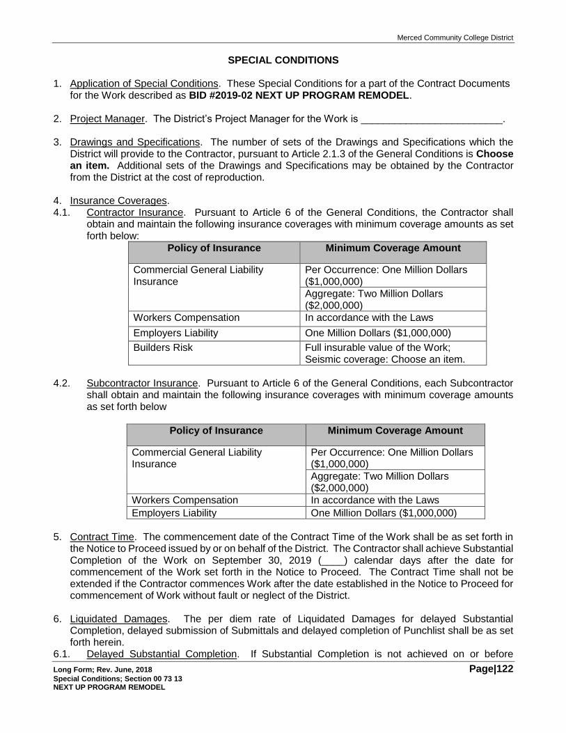
Merced Community College District
Long Form; Rev. June, 2018 Page|122 Special Conditions; Section 00 73 13 NEXT UP PROGRAM REMODEL
SPECIAL CONDITIONS 1. Application of Special Conditions. These Special Conditions for a part of the Contract Documents
for the Work described as BID #2019-02 NEXT UP PROGRAM REMODEL.
2. Project Manager. The District’s Project Manager for the Work is _________________________.
3. Drawings and Specifications. The number of sets of the Drawings and Specifications which the District will provide to the Contractor, pursuant to Article 2.1.3 of the General Conditions is Choose an item. Additional sets of the Drawings and Specifications may be obtained by the Contractor from the District at the cost of reproduction.
4. Insurance Coverages. 4.1. Contractor Insurance. Pursuant to Article 6 of the General Conditions, the Contractor shall
obtain and maintain the following insurance coverages with minimum coverage amounts as set forth below:
Policy of Insurance Minimum Coverage Amount
Commercial General Liability Insurance
Per Occurrence: One Million Dollars ($1,000,000)
Aggregate: Two Million Dollars ($2,000,000)
Workers Compensation In accordance with the Laws
Employers Liability One Million Dollars ($1,000,000)
Builders Risk Full insurable value of the Work; Seismic coverage: Choose an item.
4.2. Subcontractor Insurance. Pursuant to Article 6 of the General Conditions, each Subcontractor
shall obtain and maintain the following insurance coverages with minimum coverage amounts as set forth below
Policy of Insurance Minimum Coverage Amount
Commercial General Liability Insurance
Per Occurrence: One Million Dollars ($1,000,000)
Aggregate: Two Million Dollars ($2,000,000)
Workers Compensation In accordance with the Laws
Employers Liability One Million Dollars ($1,000,000)
5. Contract Time. The commencement date of the Contract Time of the Work shall be as set forth in
the Notice to Proceed issued by or on behalf of the District. The Contractor shall achieve Substantial Completion of the Work on September 30, 2019 (____) calendar days after the date for commencement of the Work set forth in the Notice to Proceed. The Contract Time shall not be extended if the Contractor commences Work after the date established in the Notice to Proceed for commencement of Work without fault or neglect of the District.
6. Liquidated Damages. The per diem rate of Liquidated Damages for delayed Substantial
Completion, delayed submission of Submittals and delayed completion of Punchlist shall be as set forth herein.
6.1. Delayed Substantial Completion. If Substantial Completion is not achieved on or before
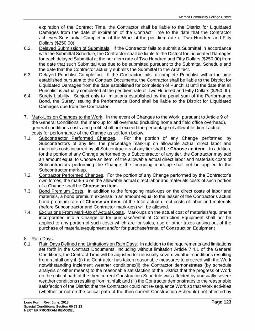
Merced Community College District
Long Form; Rev. June, 2018 Page|123 Special Conditions; Section 00 73 13 NEXT UP PROGRAM REMODEL
expiration of the Contract Time, the Contractor shall be liable to the District for Liquidated Damages from the date of expiration of the Contract Time to the date that the Contractor achieves Substantial Completion of the Work at the per diem rate of Two Hundred and Fifty Dollars ($250.00).
6.2. Delayed Submission of Submittals. If the Contractor fails to submit a Submittal in accordance with the Submittal Schedule, the Contractor shall be liable to the District for Liquidated Damages for each delayed Submittal at the per diem rate of Two Hundred and Fifty Dollars ($250.00) from the date that such Submittal was due to be submitted pursuant to the Submittal Schedule and the date that the Contractor actually submits the Submittal to the Architect.
6.3. Delayed Punchlist Completion. If the Contractor fails to complete Punchlist within the time established pursuant to the Contract Documents, the Contractor shall be liable to the District for Liquidated Damages from the date established for completion of Punchlist until the date that all Punchlist is actually completed at the per diem rate of Two Hundred and Fifty Dollars ($250.00).
6.4. Surety Liability. Subject only to limitations established by the penal sum of the Performance Bond, the Surety issuing the Performance Bond shall be liable to the District for Liquidated Damages due from the Contractor.
7. Mark-Ups on Changes to the Work. In the event of Changes to the Work, pursuant to Article 9 of
the General Conditions, the mark-up for all overhead (including home and field office overhead), general conditions costs and profit, shall not exceed the percentage of allowable direct actual costs for performance of the Change as set forth below.
7.1. Subcontractor Performed Changes. For the portion of any Change performed by Subcontractors of any tier, the percentage mark-up on allowable actual direct labor and materials costs incurred by all Subcontractors of any tier shall be Choose an item.. In addition, for the portion of any Change performed by a Subcontractor of any tier, the Contractor may add an amount equal to Choose an item. of the allowable actual direct labor and materials costs of Subcontractors performing the Change; the foregoing mark-up shall not be applied to the Subcontractor mark-up.
7.2. Contractor Performed Changes. For the portion of any Change performed by the Contractor’s own forces, the mark-up on the allowable actual direct labor and materials costs of such portion of a Change shall be Choose an item..
7.3. Bond Premium Costs. In addition to the foregoing mark-ups on the direct costs of labor and materials, a bond premium expense in an amount equal to the lesser of the Contractor’s actual bond premium rate of Choose an item. of the total actual direct costs of labor and materials (before Subcontractor and Contractor mark-ups) will be allowed.
7.4. Exclusions From Mark-Up of Actual Costs. Mark-ups on the actual cost of materials/equipment incorporated into a Change or for purchase/rental of Construction Equipment shall not be applied to any portion of such costs which are for sales, use or other taxes arising out of the purchase of materials/equipment and/or for purchase/rental of Construction Equipment
8. Rain Days. 8.1. Rain Days Defined and Limitations on Rain Days. In addition to the requirements and limitations
set forth in the Contract Documents, including without limitation Article 7.4.1 of the General Conditions, the Contract Time will be adjusted for unusually severe weather conditions resulting from rainfall only if: (i) the Contractor has taken reasonable measures to proceed with the Work notwithstanding inclement weather conditions;(ii) the Contractor demonstrates (by schedule analysis or other means) to the reasonable satisfaction of the District that the progress of Work on the critical path of the then current Construction Schedule was affected by unusually severe weather conditions resulting from rainfall; and (iii) the Contractor demonstrates to the reasonable satisfaction of the District that the Contractor could not re-sequence Work so that Work activities (whether or not on the critical path of the then current Construction Schedule) not affected by
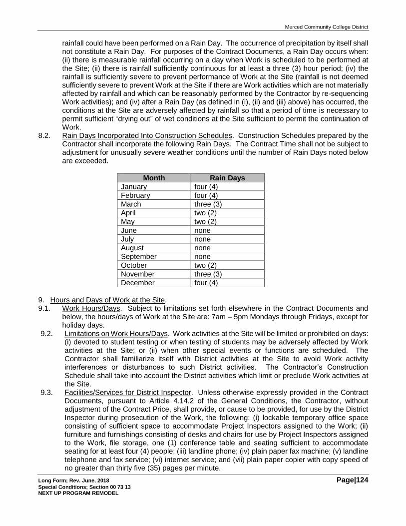
Merced Community College District
Long Form; Rev. June, 2018 Page|124 Special Conditions; Section 00 73 13 NEXT UP PROGRAM REMODEL
rainfall could have been performed on a Rain Day. The occurrence of precipitation by itself shall not constitute a Rain Day. For purposes of the Contract Documents, a Rain Day occurs when: (ii) there is measurable rainfall occurring on a day when Work is scheduled to be performed at the Site; (ii) there is rainfall sufficiently continuous for at least a three (3) hour period; (iv) the rainfall is sufficiently severe to prevent performance of Work at the Site (rainfall is not deemed sufficiently severe to prevent Work at the Site if there are Work activities which are not materially affected by rainfall and which can be reasonably performed by the Contractor by re-sequencing Work activities); and (iv) after a Rain Day (as defined in (i), (ii) and (iii) above) has occurred, the conditions at the Site are adversely affected by rainfall so that a period of time is necessary to permit sufficient “drying out” of wet conditions at the Site sufficient to permit the continuation of Work.
8.2. Rain Days Incorporated Into Construction Schedules. Construction Schedules prepared by the Contractor shall incorporate the following Rain Days. The Contract Time shall not be subject to adjustment for unusually severe weather conditions until the number of Rain Days noted below are exceeded.
Month Rain Days
January four (4)
February four (4)
March three (3)
April two (2)
May two (2)
June none
July none
August none
September none
October two (2)
November three (3)
December four (4)
9. Hours and Days of Work at the Site. 9.1. Work Hours/Days. Subject to limitations set forth elsewhere in the Contract Documents and
below, the hours/days of Work at the Site are: 7am – 5pm Mondays through Fridays, except for holiday days.
9.2. Limitations on Work Hours/Days. Work activities at the Site will be limited or prohibited on days: (i) devoted to student testing or when testing of students may be adversely affected by Work activities at the Site; or (ii) when other special events or functions are scheduled. The Contractor shall familiarize itself with District activities at the Site to avoid Work activity interferences or disturbances to such District activities. The Contractor’s Construction Schedule shall take into account the District activities which limit or preclude Work activities at the Site.
9.3. Facilities/Services for District Inspector. Unless otherwise expressly provided in the Contract Documents, pursuant to Article 4.14.2 of the General Conditions, the Contractor, without adjustment of the Contract Price, shall provide, or cause to be provided, for use by the District Inspector during prosecution of the Work, the following: (i) lockable temporary office space consisting of sufficient space to accommodate Project Inspectors assigned to the Work; (ii) furniture and furnishings consisting of desks and chairs for use by Project Inspectors assigned to the Work, file storage, one (1) conference table and seating sufficient to accommodate seating for at least four (4) people; (iii) landline phone; (iv) plain paper fax machine; (v) landline telephone and fax service; (vi) internet service; and (vii) plain paper copier with copy speed of no greater than thirty five (35) pages per minute.
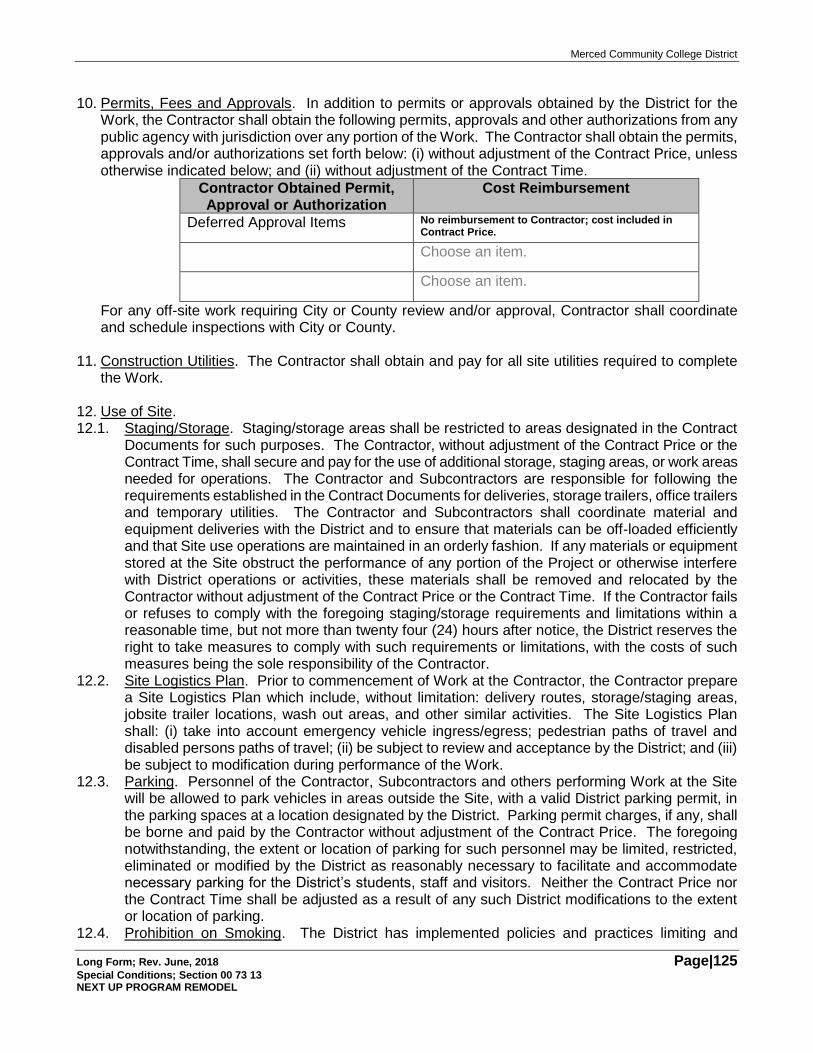
Merced Community College District
Long Form; Rev. June, 2018 Page|125 Special Conditions; Section 00 73 13 NEXT UP PROGRAM REMODEL
10. Permits, Fees and Approvals. In addition to permits or approvals obtained by the District for the
Work, the Contractor shall obtain the following permits, approvals and other authorizations from any public agency with jurisdiction over any portion of the Work. The Contractor shall obtain the permits, approvals and/or authorizations set forth below: (i) without adjustment of the Contract Price, unless otherwise indicated below; and (ii) without adjustment of the Contract Time.
Contractor Obtained Permit, Approval or Authorization
Cost Reimbursement
Deferred Approval Items No reimbursement to Contractor; cost included in Contract Price.
Choose an item.
Choose an item.
For any off-site work requiring City or County review and/or approval, Contractor shall coordinate and schedule inspections with City or County.
11. Construction Utilities. The Contractor shall obtain and pay for all site utilities required to complete
the Work. 12. Use of Site. 12.1. Staging/Storage. Staging/storage areas shall be restricted to areas designated in the Contract
Documents for such purposes. The Contractor, without adjustment of the Contract Price or the Contract Time, shall secure and pay for the use of additional storage, staging areas, or work areas needed for operations. The Contractor and Subcontractors are responsible for following the requirements established in the Contract Documents for deliveries, storage trailers, office trailers and temporary utilities. The Contractor and Subcontractors shall coordinate material and equipment deliveries with the District and to ensure that materials can be off-loaded efficiently and that Site use operations are maintained in an orderly fashion. If any materials or equipment stored at the Site obstruct the performance of any portion of the Project or otherwise interfere with District operations or activities, these materials shall be removed and relocated by the Contractor without adjustment of the Contract Price or the Contract Time. If the Contractor fails or refuses to comply with the foregoing staging/storage requirements and limitations within a reasonable time, but not more than twenty four (24) hours after notice, the District reserves the right to take measures to comply with such requirements or limitations, with the costs of such measures being the sole responsibility of the Contractor.
12.2. Site Logistics Plan. Prior to commencement of Work at the Contractor, the Contractor prepare a Site Logistics Plan which include, without limitation: delivery routes, storage/staging areas, jobsite trailer locations, wash out areas, and other similar activities. The Site Logistics Plan shall: (i) take into account emergency vehicle ingress/egress; pedestrian paths of travel and disabled persons paths of travel; (ii) be subject to review and acceptance by the District; and (iii) be subject to modification during performance of the Work.
12.3. Parking. Personnel of the Contractor, Subcontractors and others performing Work at the Site will be allowed to park vehicles in areas outside the Site, with a valid District parking permit, in the parking spaces at a location designated by the District. Parking permit charges, if any, shall be borne and paid by the Contractor without adjustment of the Contract Price. The foregoing notwithstanding, the extent or location of parking for such personnel may be limited, restricted, eliminated or modified by the District as reasonably necessary to facilitate and accommodate necessary parking for the District’s students, staff and visitors. Neither the Contract Price nor the Contract Time shall be adjusted as a result of any such District modifications to the extent or location of parking.
12.4. Prohibition on Smoking. The District has implemented policies and practices limiting and
Merced Community College District
Long Form; Rev. June, 2018 Page|126 Special Conditions; Section 00 73 13 NEXT UP PROGRAM REMODEL
restricting smoking on District property, including the Site. The Contractor is solely responsible for obtaining the District’s current non-smoking policy and: (i) notifying Subcontractors of the District’s non-smoking policies; (ii) informing employees of the Contractor and Subcontractors of the District’s non-smoking policies; (iii) posting notices at the Site summarizing the District’s non-smoking policies; (iv) complying with the Laws relating to smoking limitations and restrictions; and (v) taking appropriate actions if the District’s non-smoking policies are violated or limitations/restrictions imposed by the Laws are violated, including without limitation, removal of personnel violating such policies, limitations or restrictions.
[END OF SECTION]
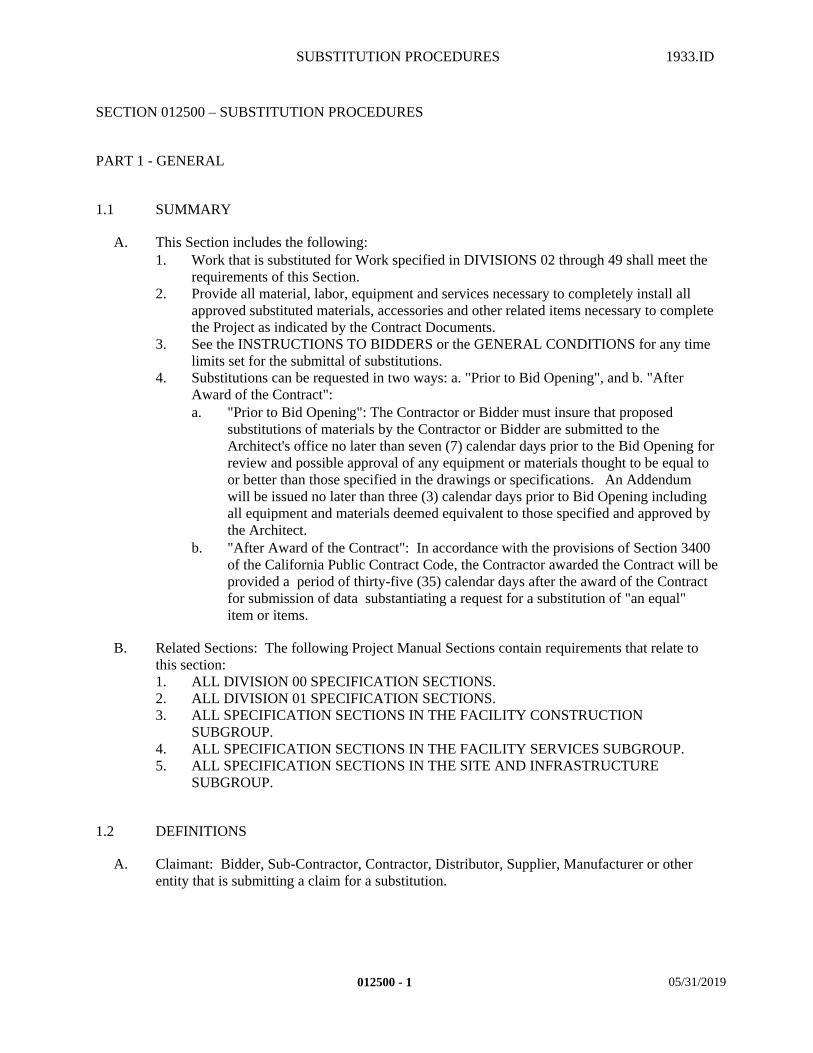
SUBSTITUTION PROCEDURES 1933.ID
SECTION 012500 – SUBSTITUTION PROCEDURES
PART 1 - GENERAL
1.1 SUMMARY
A. This Section includes the following:1. Work that is substituted for Work specified in DIVISIONS 02 through 49 shall meet the
requirements of this Section.2. Provide all material, labor, equipment and services necessary to completely install all
approved substituted materials, accessories and other related items necessary to complete the Project as indicated by the Contract Documents.
3. See the INSTRUCTIONS TO BIDDERS or the GENERAL CONDITIONS for any time limits set for the submittal of substitutions.
4. Substitutions can be requested in two ways: a. "Prior to Bid Opening", and b. "After Award of the Contract":a. "Prior to Bid Opening": The Contractor or Bidder must insure that proposed
substitutions of materials by the Contractor or Bidder are submitted to the Architect's office no later than seven (7) calendar days prior to the Bid Opening for review and possible approval of any equipment or materials thought to be equal to or better than those specified in the drawings or specifications. An Addendum will be issued no later than three (3) calendar days prior to Bid Opening including all equipment and materials deemed equivalent to those specified and approved by the Architect.
b. "After Award of the Contract": In accordance with the provisions of Section 3400 of the California Public Contract Code, the Contractor awarded the Contract will be provided a period of thirty-five (35) calendar days after the award of the Contract for submission of data substantiating a request for a substitution of "an equal" item or items.
B. Related Sections: The following Project Manual Sections contain requirements that relate to this section:1. ALL DIVISION 00 SPECIFICATION SECTIONS.2. ALL DIVISION 01 SPECIFICATION SECTIONS.3. ALL SPECIFICATION SECTIONS IN THE FACILITY CONSTRUCTION
SUBGROUP.4. ALL SPECIFICATION SECTIONS IN THE FACILITY SERVICES SUBGROUP.5. ALL SPECIFICATION SECTIONS IN THE SITE AND INFRASTRUCTURE
SUBGROUP.
1.2 DEFINITIONS
A. Claimant: Bidder, Sub-Contractor, Contractor, Distributor, Supplier, Manufacturer or other entity that is submitting a claim for a substitution.
012500 - 1 05/31/2019
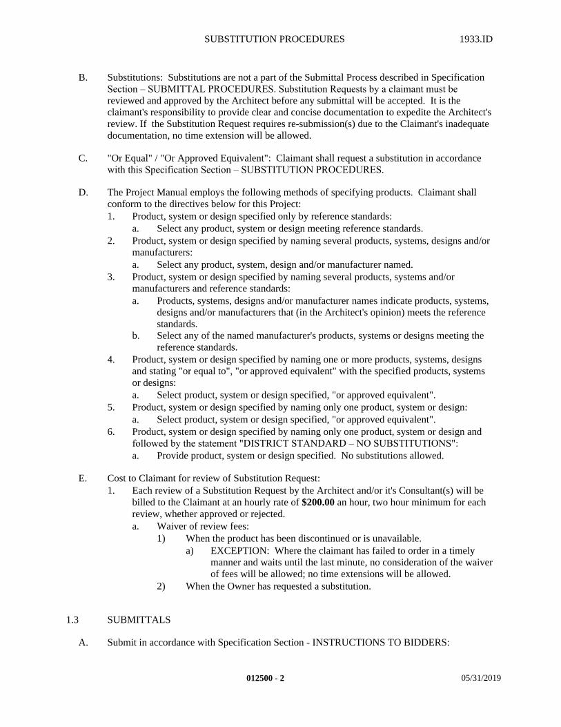
SUBSTITUTION PROCEDURES 1933.ID
B. Substitutions: Substitutions are not a part of the Submittal Process described in Specification Section – SUBMITTAL PROCEDURES. Substitution Requests by a claimant must be reviewed and approved by the Architect before any submittal will be accepted. It is the claimant's responsibility to provide clear and concise documentation to expedite the Architect's review. If the Substitution Request requires re-submission(s) due to the Claimant's inadequate documentation, no time extension will be allowed.
C. "Or Equal" / "Or Approved Equivalent": Claimant shall request a substitution in accordance with this Specification Section – SUBSTITUTION PROCEDURES.
D. The Project Manual employs the following methods of specifying products. Claimant shall conform to the directives below for this Project:1. Product, system or design specified only by reference standards:
a. Select any product, system or design meeting reference standards.2. Product, system or design specified by naming several products, systems, designs and/or
manufacturers:a. Select any product, system, design and/or manufacturer named.
3. Product, system or design specified by naming several products, systems and/or manufacturers and reference standards:a. Products, systems, designs and/or manufacturer names indicate products, systems,
designs and/or manufacturers that (in the Architect's opinion) meets the reference standards.
b. Select any of the named manufacturer's products, systems or designs meeting the reference standards.
4. Product, system or design specified by naming one or more products, systems, designs and stating "or equal to", "or approved equivalent" with the specified products, systems or designs:a. Select product, system or design specified, "or approved equivalent".
5. Product, system or design specified by naming only one product, system or design:a. Select product, system or design specified, "or approved equivalent".
6. Product, system or design specified by naming only one product, system or design and followed by the statement "DISTRICT STANDARD – NO SUBSTITUTIONS":a. Provide product, system or design specified. No substitutions allowed.
E. Cost to Claimant for review of Substitution Request:1. Each review of a Substitution Request by the Architect and/or it's Consultant(s) will be
billed to the Claimant at an hourly rate of $200.00 an hour, two hour minimum for each review, whether approved or rejected.a. Waiver of review fees:
1) When the product has been discontinued or is unavailable.a) EXCEPTION: Where the claimant has failed to order in a timely
manner and waits until the last minute, no consideration of the waiver of fees will be allowed; no time extensions will be allowed.
2) When the Owner has requested a substitution.
1.3 SUBMITTALS
A. Submit in accordance with Specification Section - INSTRUCTIONS TO BIDDERS:
012500 - 2 05/31/2019
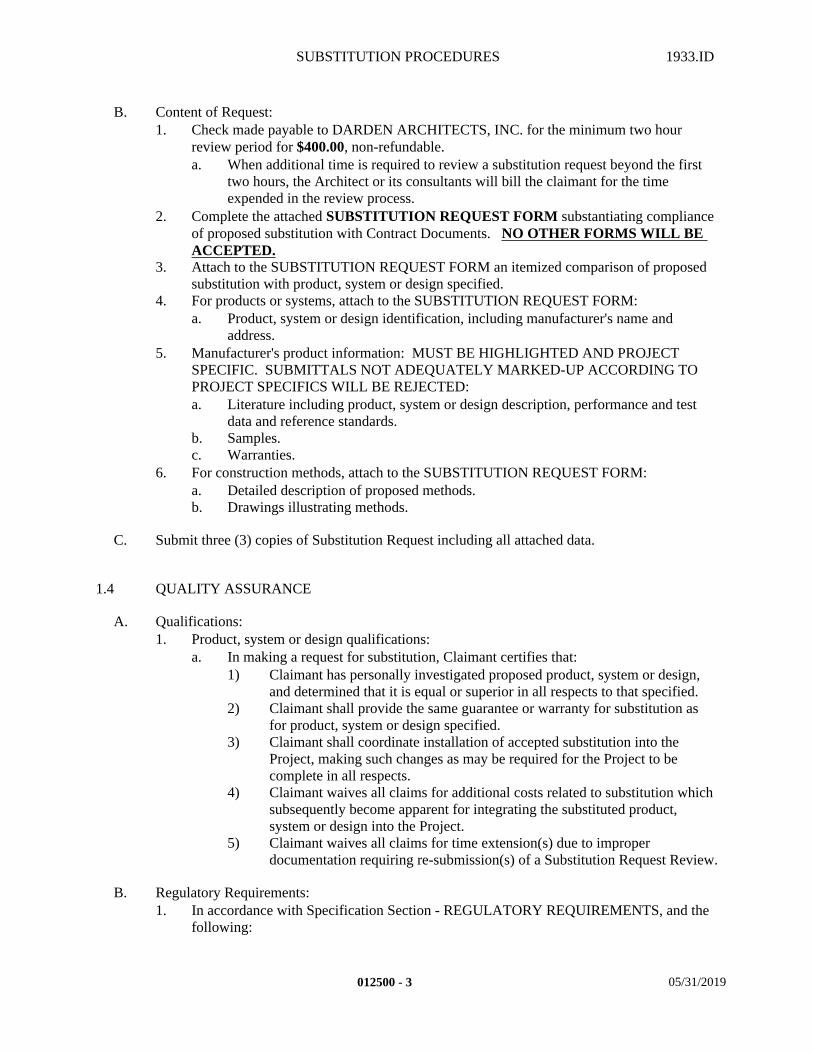
SUBSTITUTION PROCEDURES 1933.ID
B. Content of Request:1. Check made payable to DARDEN ARCHITECTS, INC. for the minimum two hour
review period for $400.00, non-refundable.a. When additional time is required to review a substitution request beyond the first
two hours, the Architect or its consultants will bill the claimant for the time expended in the review process.
2. Complete the attached SUBSTITUTION REQUEST FORM substantiating compliance of proposed substitution with Contract Documents. NO OTHER FORMS WILL BE ACCEPTED.
3. Attach to the SUBSTITUTION REQUEST FORM an itemized comparison of proposed substitution with product, system or design specified.
4. For products or systems, attach to the SUBSTITUTION REQUEST FORM:a. Product, system or design identification, including manufacturer's name and
address.5. Manufacturer's product information: MUST BE HIGHLIGHTED AND PROJECT
SPECIFIC. SUBMITTALS NOT ADEQUATELY MARKED-UP ACCORDING TO PROJECT SPECIFICS WILL BE REJECTED:a. Literature including product, system or design description, performance and test
data and reference standards.b. Samples.c. Warranties.
6. For construction methods, attach to the SUBSTITUTION REQUEST FORM:a. Detailed description of proposed methods.b. Drawings illustrating methods.
C. Submit three (3) copies of Substitution Request including all attached data.
1.4 QUALITY ASSURANCE
A. Qualifications:1. Product, system or design qualifications:
a. In making a request for substitution, Claimant certifies that:1) Claimant has personally investigated proposed product, system or design,
and determined that it is equal or superior in all respects to that specified.2) Claimant shall provide the same guarantee or warranty for substitution as
for product, system or design specified.3) Claimant shall coordinate installation of accepted substitution into the
Project, making such changes as may be required for the Project to be complete in all respects.
4) Claimant waives all claims for additional costs related to substitution which subsequently become apparent for integrating the substituted product, system or design into the Project.
5) Claimant waives all claims for time extension(s) due to improper documentation requiring re-submission(s) of a Substitution Request Review.
B. Regulatory Requirements:1. In accordance with Specification Section - REGULATORY REQUIREMENTS, and the
following:
012500 - 3 05/31/2019
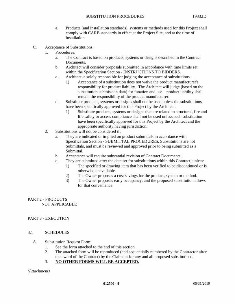
SUBSTITUTION PROCEDURES 1933.ID
a. Products (and installation standards), systems or methods used for this Project shall comply with CARB standards in effect at the Project Site, and at the time of installation.
C. Acceptance of Substitutions:1. Procedures:
a. The Contract is based on products, systems or designs described in the Contract Documents.
b. Architect will consider proposals submitted in accordance with time limits set within the Specification Section - INSTRUCTIONS TO BIDDERS.
c. Architect is solely responsible for judging the acceptance of substitutions.1) Acceptance of a substitution does not waive the product manufacturer's
responsibility for product liability. The Architect will judge (based on the substitution submission data) for function and use – product liability shall remain the responsibility of the product manufacturer.
d. Substitute products, systems or designs shall not be used unless the substitutions have been specifically approved for this Project by the Architect.1) Substitute products, systems or designs that are related to structural, fire and
life safety or access compliance shall not be used unless such substitution have been specifically approved for this Project by the Architect and the appropriate authority having jurisdiction.
2. Substitutions will not be considered if:a. They are indicated or implied on product submittals in accordance with
Specification Section - SUBMITTAL PROCEDURES. Substitutions are not Submittals, and must be reviewed and approved prior to being submitted as a Submittal.
b. Acceptance will require substantial revision of Contract Documents.c. They are submitted after the date set for substitutions within this Contract, unless:
1) The specified or drawing item that has been verified to be discontinued or is otherwise unavailable.
2) The Owner proposes a cost savings for the product, system or method.3) The Owner proposes early occupancy, and the proposed substitution allows
for that convenience.
PART 2 - PRODUCTSNOT APPLICABLE
PART 3 - EXECUTION
3.1 SCHEDULES
A. Substitution Request Form:1. See the form attached to the end of this section.2. The attached form will be reproduced (and sequentially numbered by the Contractor after
the award of the Contract) by the Claimant for any and all proposed substitutions.3. NO OTHER FORMS WILL BE ACCEPTED.
(Attachment)
012500 - 4 05/31/2019
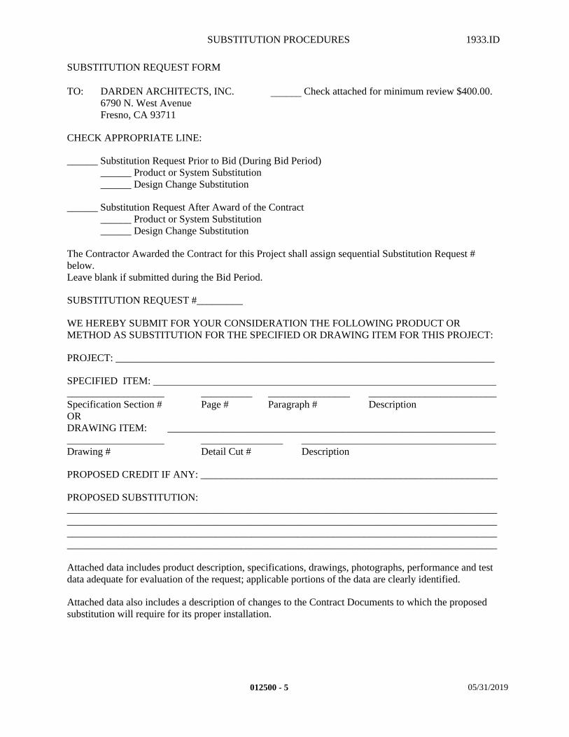
SUBSTITUTION PROCEDURES 1933.ID
SUBSTITUTION REQUEST FORM
TO: DARDEN ARCHITECTS, INC. ______ Check attached for minimum review $400.00.6790 N. West AvenueFresno, CA 93711
CHECK APPROPRIATE LINE:
______ Substitution Request Prior to Bid (During Bid Period)______ Product or System Substitution______ Design Change Substitution
______ Substitution Request After Award of the Contract______ Product or System Substitution______ Design Change Substitution
The Contractor Awarded the Contract for this Project shall assign sequential Substitution Request # below.Leave blank if submitted during the Bid Period.
SUBSTITUTION REQUEST #_________
WE HEREBY SUBMIT FOR YOUR CONSIDERATION THE FOLLOWING PRODUCT OR METHOD AS SUBSTITUTION FOR THE SPECIFIED OR DRAWING ITEM FOR THIS PROJECT:
PROJECT: __________________________________________________________________________
SPECIFIED ITEM: ______________________________________________________________________________________ __________ ________________ _________________________Specification Section # Page # Paragraph # DescriptionORDRAWING ITEM: ___________________________________________________________________________________ ________________ ______________________________________Drawing # Detail Cut # Description
PROPOSED CREDIT IF ANY: __________________________________________________________
PROPOSED SUBSTITUTION:________________________________________________________________________________________________________________________________________________________________________________________________________________________________________________________________________________________________________________________________________________
Attached data includes product description, specifications, drawings, photographs, performance and test data adequate for evaluation of the request; applicable portions of the data are clearly identified.
Attached data also includes a description of changes to the Contract Documents to which the proposed substitution will require for its proper installation.
012500 - 5 05/31/2019
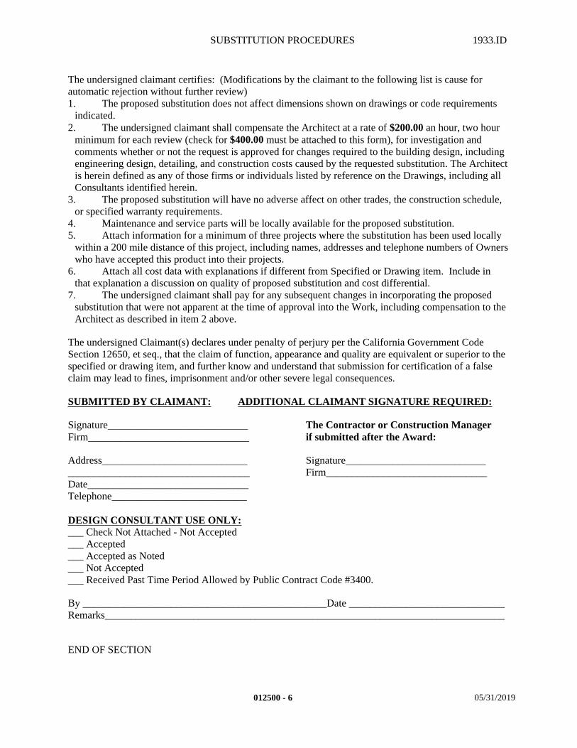
SUBSTITUTION PROCEDURES 1933.ID
The undersigned claimant certifies: (Modifications by the claimant to the following list is cause for automatic rejection without further review)1. The proposed substitution does not affect dimensions shown on drawings or code requirements
indicated.2. The undersigned claimant shall compensate the Architect at a rate of $200.00 an hour, two hour
minimum for each review (check for $400.00 must be attached to this form), for investigation and comments whether or not the request is approved for changes required to the building design, including engineering design, detailing, and construction costs caused by the requested substitution. The Architect is herein defined as any of those firms or individuals listed by reference on the Drawings, including all Consultants identified herein.
3. The proposed substitution will have no adverse affect on other trades, the construction schedule, or specified warranty requirements.
4. Maintenance and service parts will be locally available for the proposed substitution.5. Attach information for a minimum of three projects where the substitution has been used locally
within a 200 mile distance of this project, including names, addresses and telephone numbers of Owners who have accepted this product into their projects.
6. Attach all cost data with explanations if different from Specified or Drawing item. Include in that explanation a discussion on quality of proposed substitution and cost differential.
7. The undersigned claimant shall pay for any subsequent changes in incorporating the proposed substitution that were not apparent at the time of approval into the Work, including compensation to the Architect as described in item 2 above.
The undersigned Claimant(s) declares under penalty of perjury per the California Government Code Section 12650, et seq., that the claim of function, appearance and quality are equivalent or superior to the specified or drawing item, and further know and understand that submission for certification of a false claim may lead to fines, imprisonment and/or other severe legal consequences.
SUBMITTED BY CLAIMANT: ADDITIONAL CLAIMANT SIGNATURE REQUIRED:
Signature___________________________ The Contractor or Construction ManagerFirm_______________________________ if submitted after the Award:
Address____________________________ Signature______________________________________________________________ Firm_______________________________Date_______________________________Telephone__________________________
DESIGN CONSULTANT USE ONLY:___ Check Not Attached - Not Accepted___ Accepted___ Accepted as Noted___ Not Accepted___ Received Past Time Period Allowed by Public Contract Code #3400.
By _______________________________________________Date ______________________________Remarks_____________________________________________________________________________
END OF SECTION
012500 - 6 05/31/2019
SUBMITTAL PROCEDURES 1933.ID
SECTION 013300 – SUBMITTAL PROCEDURES
PART 1 - GENERAL
1.1 SUMMARY
A. This Section includes the following:1. Provide all material, labor, equipment and services necessary to completely provide all
required submittals and other related items necessary to complete the Project as indicated by the Contract Documents.
B. Related Sections: The following Project Manual Sections contain requirements that relate to this section:1. ALL DIVISION 00 SPECIFICATION SECTIONS.2. ALL DIVISION 01 SPECIFICATION SECTIONS.3. ALL SPECIFICATION SECTIONS IN THE FACILITY CONSTRUCTION
SUBGROUP.4. ALL SPECIFICATION SECTIONS IN THE FACILITY SERVICES SUBGROUP.5. ALL SPECIFICATION SECTIONS IN THE SITE AND INFRASTRUCTURE
SUBGROUP.
1.2 SUBMITTALS
A. Request for Electronic Files:1. Submit in accordance with the following:
a. Contractor's Usage Agreement for Electronic Files:1) See attachment.
B. Contractor's responsibilities:1. The Contractor shall check, verify, and be responsible for all field measurements.2. The Contractor shall submit a schedule indicating when the required shop drawings and
submittals will be submitted to the Architect.a. Submit schedule within the amount of days as indicated in Specification Section -
CONSTRUCTION SCHEDULES.3. Submit copies as scheduled below, checked and approved by the Contractor for all
submittals required for the work of the various trades. Deliver submittals promptly to avoid delays in delivery of materials or execution of the work.a. The Contractor (or Subcontractor) shall mark-up the submittals as to project
specifics. If the specifications contains a schedule prepared by the Architect (i.e. paint symbols such as DW-1, M-1, CB-1, etc., or tile symbols such as CT-1,CT-2, or IWA, IWB, IWC, etc.), then the submittal will also contain those designations. Submittals without project specifics will be returned to the Contractor as not being properly prepared.
b. The Contractor shall stamp the Submittals utilizing any language requested by the Owner in the General Conditions and the following minimum language:
"This submittal has been reviewed by (Name of Contractor) and approved with respect to the means,
013300 - 1 05/31/2019
SUBMITTAL PROCEDURES 1933.ID
methods, techniques, sequences, and procedures of construction, and safety precautions and programs incidental thereto. The Contractor has reviewed and approved not only the field dimensions, but the construction criteria, and has also made written notation regarding any information in the Shop Drawings that does not conform to the Contract Documents. The Contractor has reviewed this submittal and coordinated with all other Shop Drawings received to date by the Contractor and this duty of coordination has not been delegated to subcontractors, material suppliers, the Architect, or the design consultants on this project. The Contractor shall also have indicated that it has not relied upon the dimensions shown on the drawings, specifications and schedules, and that the Contractor has double-checked all dimensions for accuracy and fit. (Name of Contractor) also warrants that this submittal complies with the Contract Documents and comprises no variation thereto."
By: _______________________________________ Contractor's Signature
_____________________________________Contractor's Typed Name
Date: ______________________________________c. Substitutions on shop drawings or in product submittals will not be considered
without prior approval in accordance with Specification Section - SUBSTITUTION PROCEDURES. Submittals containing unacceptable items will be rejected.
d. The Contractor shall make any corrections required by the Architect during the Architect's initial review, and re-submit the required corrected copies for final review and distribution.
C. Architect's responsibilities:1. The Architect will make any desired corrections with reasonable promptness, and return
the submittal to the Contractor.2. The Architect's review of such drawings or schedules shall not relieve the Contractor of
responsibility for deviations from the drawings or specifications, unless he has, in writing, called the Architect's attention to such deviations at the time of submission, and secured written acceptance.a. The Architect's review shall be for general conformance with the design concept
for the project and general compliance with the information given in the Contract Documents.
b. The Architect's review shall not be construed as an "approval", or to relieve the Contractor(s) and material suppliers of responsibility for errors or omissions in the submitted documents.
c. Modifications or comments made on the submittals or shop drawings during this review do not relieve the Contractor from compliance with the requirements of the drawings and specifications.
d. Acceptance of a specific item does not include acceptance of the assembly of which the item is a component.
D. The following list of items, definitions and required quantities is a minimum required for this project. Verify with FACILITY SERVICES SUBGROUP sections for additional quantities required within those divisions.1. Product Data: Illustrations, standard schedules, performance charts, instructions,
brochures, diagrams, other product information, color choices and/or manufacturer's catalog sheets shall be specially prepared for the Project (marked-up with project specifics) and shall be submitted in sequential sets for each category of work:a. Quantity:
1) Unless otherwise indicated in the Contract Documents, provide Six (6) sets.
013300 - 2 05/31/2019
SUBMITTAL PROCEDURES 1933.ID
b. Material Safety Data Sheets (MSDS): MSDS are not required, but it is recognized that applicable federal and state laws require the submission of these data sheets to an Owner. MSDS shall be turned over to the Owner (without review by the Architect or it's consultants) in compliance with federal and state laws.
2. Shop Drawings: Newly prepared information, drawn to accurate scale, consisting of drawings, diagrams, schedules, and other data specifically prepared for the Project by the Contractor, a Subcontractor, manufacturer, supplier or distributor to illustrate some portion of the Project. Do not reproduce Contract Documents or copy Standard information as the basis of Shop Drawings. Standard information prepared without specific reference to the Project is not considered Shop Drawings.a. Quantity: Provide One (1) reproducible original (vellum, sepia or mylar) and
Three (3) opaque (blue-line or black-line xerographic) prints for each sheet or detail. 1) The contractor shall receive the marked-up reproducibles and copy the
required number of sets to the subcontractor, manufacturer's and/or material suppliers.
b. Contractor's use of Architect's Electronic CAD Files.1) Upon written request by Contractor, copies of the Architect's electronic
CAD files may be available for Contractor's use in connection with this Project.a) Contractor's written request shall be on the Architect's "Contractor's
Document Usage Agreement for Requested Documents" and may include an additional Architect's Consultant's Agreements, outlining conditions for providing files.
b) Contractor's request shall be limited to drawings directly applicable to the Shop Drawings the Contractor wishes to create for submittal.
c) Contractor shall pay the Architect for work incurred for providing the requested files. Payment shall be submitted with the request.
2) The Architect's electronic CAD files are limited to files that already exist and that not all files may be available at the Architect's and Architect's Consultant's discretion.
3) The Architect's electronic CAD files are not part of the Contract Documents and have limitations to the accuracy, incorporating modifications, CAD system formats, CAD entity attributes and layering.
4) The Architect's electronic CAD files have restrictions on Contractor's use, transmittal and delivery of files.
3. Samples: Physical examples specially prepared for the Project (marked-up with project specifics) which illustrate materials, equipment, or workmanship and establish standards by which the Work will be judged.a. Quantity:
1) Unless otherwise indicated in the Contract Documents, provide Four (4) sets.
b. Color samples shall be submitted on 8-1/2" x 11" cards for all colors scheduling paint types specified utilizing the paint symbols designated by the Architect in the drawings and specifications.
c. Manufactured devices or equipment items:1) Quantity: One (1) sample, returned to supplier and which, when approved,
may be incorporated into the Project.4. Quality Assurance/Control submittals: Consists of design data, test reports, certificates,
manufacturers instructions, and /or manufacturer's field reports.
013300 - 3 05/31/2019
SUBMITTAL PROCEDURES 1933.ID
a. Quantity:1) Unless otherwise indicated in the Contract Documents, provide Six (6) sets.
5. Closeout submittals: Maintenance data, operating manuals, project documents, engineering calculations, and/or warranties shall be submitted when required in the various specification sections:a. Quantity:
1) Unless otherwise indicated in the Contract Documents, provide Two (2) sets.
6. Field Samples: Sample panels of in place construction, or selected area of completed substrates or work showing the anticipated compliance with specified characteristics in order to establish a standard of quality.a. Quantity:
1) See specific specification section requirements.
E. Substitution, Dispute or Claim Submittals:1. Any substitution, dispute or claim submittals relating to this contract, or any Contract
breach, which are not disposed of by agreement shall be promptly submitted in accordance with the GENERAL CONDITIONS, as a claim to and decided by the Architect who shall issue a written decision on the dispute.
2. Adequate supporting data shall include, but is not limited; a statement of the reasons for the asserted entitlement, the certified payroll, invoice for material and equipment rental, and an itemized breakdown of any adjustment sought.
3. If no "SUBMISSION UNDER PENALTY OF PERJURY" clause is provided within the GENERAL CONDITIONS, then the Contractor shall certify, at the time of submission of a substitution, dispute or claim, as follows:
(The rest of this page is left intentionally blank)
013300 - 4 05/31/2019
SUBMITTAL PROCEDURES 1933.ID
SUBMISSION UNDER PENALTY OF PERJURY
I _____________________________________, being the ___________________(Must be an officer), declare under penalty of perjury under the laws of the State of California, and do personally certify and attest that: I have thoroughly reviewed the attached substitution, dispute or claim for additional compensation and/or extension of time, and know its contents, and said claim is made in good faith; the supporting data is truthful and accurate; that the amount required accurately reflects the contract adjustment for which the Contractor believes the Owner is liable; and further, that I am familiar with California Government Code Section 12650, et seq, pertaining to false claims, and further know and understand that submission of certification of a false claim may lead to fines, imprisonment and/or other severe legal consequences.
By: _______________________________________ Contractor's Signature
_______________________________________ Contractor's Typed Name
Date: ______________________________________
Submission of a substitution, dispute or claim, properly certified, with all required supporting documentation, and written rejection or denial or all or part of the claim by Owner, is a condition precedent to any action, proceeding, litigation, suit or demand for arbitration by Contractor.
(This page is left intentionally blank)
013300 - 5 05/31/2019
SUBMITTAL PROCEDURES 1933.ID
PART 2 - PRODUCTS
NOT APPLICABLE
PART 3 - EXECUTION
3.1 SCHEDULES
A. Usage Agreement For Electronic Documents:1. Contractor's Usage Agreement for Electronic Files:
a. See attachment.
B. The following schedule was prepared to assist the Contractor in knowing the required submittals for this project, but may not be complete. Specific submittal information as to what is required is contained within the individual specification sections and those individual sections shall govern in the event of a question.
C. SUBMITTAL SCHEDULE1. 01 11 13 - SUMMARY OF WORK
a. QUALITY ASSURANCE/ CONTROL SUBMITTALS2. 01 25 00 - SUBSTITUTION PROCEDURES
a. SUBSTITUTION REQUEST FORMS3. 01 29 73 - SCHEDULE OF VALUES4. 01 45 29 - TESTING LABORATORY SERVICES
a. TESTING SCHEDULE, TEST REPORTS5. 01 77 20 - PROJECT CLOSEOUT
a. ANOTATED CONTRACTOR’S AND ARCHITECT’S PUNCH LIST. ALL OPERATIONAL DATA, ALL MAINTENANCE MANUALS, ALL EXTRA MATERIALS.
6. 01 78 36 - WARRANTIESa. ALL GUARANTEES AND WARRANTIES
7. 01 78 39 - PROJECT DOCUMENTSa. PROJECT "AS-BUILT" DOCUMENTS, PROJECT "RECORD" DOCUMENTS
AND PROJECT "CERTIFICATION" DOCUMENTS.8. 03 15 14 - DRILLED ANCHORS
a. PRODUCT DATA, ICC EVALUATION SERVICE REPORTS, DSA APPROVAL LETTERS.
9. 03 20 00 - REINFORCEMENTa. SHOP DRAWINGS, QUALITY ASSURANCE/CONTROL SUBMITTALS,
CLOSEOUT SUBMITTALS.10. 03 30 00 - CAST-IN-PLACE CONCRETE
a. PRODUCT DATA, QUALITY ASSURANCE/CONTROL SUBMITTALS, CLOSEOUT SUBMITTALS.
11. 03 37 13 - SHOTCRETEa. PRODUCT DATA, QUALITY ASSURANCE/CONTROL SUBMITTALS,
CLOSEOUT SUBMITTALS.
013300 - 6 05/31/2019
SUBMITTAL PROCEDURES 1933.ID
12. 05 30 00 - METAL DECKa. PRODUCT DATA, SHOP DRAWINGS, QUALITY ASSURANCE/CONTROL
SUBMITTALS, CLOSEOUT SUBMITTALS.13. 07 51 13 - BUILT-UP ROOFING (Cold)
a. PRODUCT DATA, SHOP DRAWINGS AND WARRANTIES.14. 08 91 00 - LOUVERS
a. PRODUCT DATA, SHOP DRAWINGS, CERTIFICATES AND COLORS.15. 10 05 00 - MISCELLANEOUS SPECIALTIES
a. PRODUCT DATA, COLORS AND SAMPLES (WHERE APPLICABLE) FOR ALL ITEMS.
16. 31 20 00 - EARTHWORKa. PRODUCT DATA, SHOP DRAWINGS, QUALITY ASSURANCE/CONTROL
SUBMITTALS, PROJECT RECORD DOCUMENTS, AND WARRANTIES, AND DRAWINGS SHOWING KNOWLEDGE OF THE EXTENT OF ENGINEERED PADS.
CONTRACTOR'SUSAGE AGREEMENT FOR ELECTRONIC FILES -
ELECTRONIC FILE REQUEST FORM
Project Name: _______________________________________________________
DA Project No.: _______________________________________________________
TO: DARDEN ARCHITECTS, INC.
6790 N. West Avenue
Fresno CA 93711
A. I as a duly authorized agent of
, have a contract with the Owner to perform work on the above project in the following capacity:___ Lease-Lease Back Agent___ Construction Manager___ General Contractor
B. We hereby submit for your consideration a request for Electronic Files on the behalf of
, and certify that they have a contract or subcontract to perform work on the above named project in the following capacity:___ General Contractor___ Sub-Contractor___ Others under contract to a sub-contractor
C. I , certify the required attachments are included as follows:
___ Completed "Usage Agreement for Electronic Files Agreement•" along with appropriate related
013300 - 7 05/31/2019
SUBMITTAL PROCEDURES 1933.ID
supplemental Agreements.___ Files requested are specific and are not deemed vague or excessive and with individual sheet
numbers identified, and the total number of sheets are correct.___ The enclosed Payment is accurate ($120 per sheet) and is made payable to Darden Architects,
Inc..
___________________________________________ __________________________Print Name, Title
___________________________________________ __________________________Signature Date
013300 - 8 05/31/2019
SUBMITTAL PROCEDURES 1933.ID
CONTRACTOR'S USAGE AGREEMENT FOR ELECTRONIC FILES
PROJECT NAME: _____________________________________________________
DA PROJECT NO.: _____________________________________________________
PROJECT ARCHITECT: _____________________________________________________
I ______________________________________, as a duly authorized agent of______________________________________ - (Contractor) have a contract or subcontract to perform work on the above named project. The Contractor acknowledges having received at least one (1) complete set of Contract Documents for the project and has posted all Addenda and all other contract documents issued to date.
Contractor Document Usage Agreement
The Contractor is requesting the electronic CAD files of work prepared by the Architect and/or Architect's Consultants (Design Team) on the subject project, so that the information therein may be utilized in the Contractor's work on the same project. The Contractor understands that these files are being provided as a courtesy and they are strictly intended for the Contractor's sole convenience and they are not recognized Contract Documents. This request is subject to the following conditions, which the Contractor hereby agrees to abide by:
1. It is understood and agreed to that any files and/or documents provided are instruments of professional service by the Design Team and are intended for one-time use solely in the construction of this project. They are and shall remain the property of the Architect or the Architect's Consultants, who is deemed to be the author of the drawings and data, and who shall retain all common law, statutory law, and all other rights, including copyrights.
2. The Contractor shall indemnify and hold harmless, the Design Team, its officers, directors, employees or subcontractors, to the fullest extent permitted by law, against all claims, liabilities, losses, damages, and costs, including but not limited to attorney's fees and defense costs arising out of or resulting from contractor's use of these electronic files, or in any way connected with the modification, misinterpretation, misuse, or reuse by the Contractor or by others.
3. The Contractor agrees that by using these electronic files, the Contractor is in no way relieved of the duty to fully comply with the Contract Documents, including and without limitation, the need to check, confirm and coordinate all dimensions and other details, take field measurements, verify field conditions and coordinate with all other contractors for the project.
4. It is agreed to that these electronic files are not Contract Documents. Differences may exist between electronic files and corresponding hard-copy Contract documents. The Design Team makes no representation regarding the accuracy or completeness of the electronic files provided to the contractor. In the event that a conflict arises, the signed and sealed hard-copy Contract Documents shall govern. Contractor is responsible for determining if any conflict exists.
5. The Contractor understands that the Design Team makes no representation as to the compatibility of these files with Contractor's computer hardware or software. The Contractor understands that the accuracy of the information is an artifact of the techniques used to generate it and is in no way intended to imply actual accuracy. It is also understood that the automated conversion of information and data
013300 - 9 05/31/2019
SUBMITTAL PROCEDURES 1933.ID
from the system and format used by the Design Team to an alternate system or format cannot be accomplished without the possibility of introduction of inexactitudes, anomalies and errors.
6. Because information presented on the electronic files can be modified, unintentionally or otherwise, the Design Team reserves the right to edit the drawings to remove information deemed not necessary and/or remove all indications of ownership and/or involvement from each electronic display.
7. The Design Team will only furnish those drawings directly applicable to the shop drawings the contractor wishes to create. The Contractor understands that not all electronic files may be available at the Design Team's discretion.
8. The Contractor understands that the Architect's Consultants may have Additional Conditions for release of their electronic files or documents, and the Contractor hereby agree to abide by the Consultants conditions in addition to the stated conditions in this agreement. Additional Conditions (if any) are attached to this agreement.
9. The Contractor understands that the Architect and the Architect's Consultants will incur certain costs in providing the requested electronic files. The Contractor agrees to pay the Design Team a service fee of $120.00 per sheet, per delivery, prior to any delivery of the electronic files to compensate the Design Team for the labor to prepare and transmit the files and for the additional risk that this transfer will occasion.
10. Under no circumstances shall delivery of the electronic files for use by the Contractor be deemed a sale by the Owner, the Design Team, or any member of the Design Team. The Design Team makes no warranties, either expressed or implied, of merchantability or fitness for any particular purpose. In no event shall the Design Team be liable for any loss of profit or any consequential damages as a result of Contractor's use or reuse of the electronic files.
Darden Architects, Inc.
Attachments:___ Civil ___ Structural ___ Mechanical ___ Electrical ___ Others
Description of the requested documents and/or CAD files:________________________________________________________________________________________________________________________________________________________
_____________________________ _______________________Printed Name Title
_____________________________ _______________________Signed DatedFOR USE BY ARCHITECT ONLY___ Check Not Attached – Not Accepted___ Accepted___ Accepted as Noted___ Not AcceptedBy______________________________Date____________________________Remarks_________________________________________________________
013300 - 10 05/31/2019
SUBMITTAL PROCEDURES 1933.ID
END OF SECTION
013300 - 11 05/31/2019

CUTTING AND PATCHING 1933.ID
SECTION 017329 – CUTTING AND PATCHING
PART 1 - GENERAL
1.1 SUMMARY
A. This Section includes the following:1. Provide all material, labor, equipment and services necessary for cutting and patching
existing materials, accessories and other related items necessary to remodel the Project as indicated by the Contract Documents.
B. Related Sections: The following Project Manual Sections contain requirements that relate to this section:1. ALL DIVISION 00 SPECIFICATION SECTIONS.2. ALL DIVISION 01 SPECIFICATION SECTIONS.3. ALL SPECIFICATION SECTIONS IN THE FACILITY CONSTRUCTION
SUBGROUP.4. ALL SPECIFICATION SECTIONS IN THE FACILITY SERVICES SUBGROUP.5. ALL SPECIFICATION SECTIONS IN THE SITE AND INFRASTRUCTURE
SUBGROUP.
1.2 DEFINITIONS
A. Cutting: Removal of existing construction necessary to permit installation or performance of Work.
B. Patching: Fitting and repair work required to restore surfaces to original conditions after installation of Work.
1.3 SUBMITTALS
A. Submit in accordance with Specification Section - SUBMITTAL PROCEDURES:1. Coordination Drawings:
a. Submit any installer's coordination drawings indicating the work of this section with that of related work of other sections for proper interface of the completed work. Installer shall coordinate and obtain approvals from the work of other related sections prior to submitting to the Architect.
1.4 QUALITY ASSURANCE
A. Cutting and Patching Conference: Before proceeding, meet at Project site with parties involved in cutting and patching, including mechanical and electrical trades.1. Review areas of potential interference and conflict.2. Coordinate procedures and resolve potential conflicts before proceeding.
017329 - 1 05/29/2019
CUTTING AND PATCHING 1933.ID
B. Structural Elements: Do not cut and patch structural elements in a manner that could change their load-carrying capacity or load-deflection ratio.
C. Operational Elements: Do not cut and patch operating elements and related components in a manner that results in reducing their capacity to perform as intended or that results in increased maintenance or decreased operational life or safety.
D. Visual Requirements: Do not cut and patch construction in a manner that results in visual evidence of cutting and patching. Do not cut and patch construction exposed on the exterior or in occupied spaces in a manner that would, in Architect's opinion, reduce the building's aesthetic qualities. Remove and replace construction that has been cut and patched in a visually unsatisfactory manner.
E. The Contractor shall do all cutting, fitting or patching of existing construction and his work as may be required to make the several parts come together properly and ready to receive or be received by work of other contractors as shown, or reasonably implied by the drawings and specifications for the completed structure. All work shall be as directed by the Architect to achieve the intended work and degree of finish shown.
F. Any cost caused by defective or ill-timed work shall be borne by the party responsible therefor.
1.5 WARRANTY
A. Existing Warranties: Remove, replace, patch, and repair materials and surfaces cut or damaged during cutting and patching operations, by methods and with materials so as not to void existing warranties.
PART 2 - PRODUCTS
2.1 MATERIALS
A. General: Comply with requirements specified in other Sections of these Specifications.
B. Existing Materials: Use materials identical to existing materials. For exposed surfaces, use materials that visually match existing adjacent surfaces to the fullest extent possible.1. If identical materials are unavailable or cannot be used, use materials that, when installed,
will match the visual and functional performance of existing materials.
PART 3 - EXECUTION
3.1 EXAMINATION
A. Examine surfaces to be cut and patched and conditions under which cutting and patching are to be performed.1. Compatibility: Before patching, verify compatibility with and suitability of substrates,
including compatibility with existing finishes or primers.
017329 - 2 05/29/2019
CUTTING AND PATCHING 1933.ID
2. Proceed with installation only after unsafe or unsatisfactory conditions have been corrected.
3.2 PREPARATION
A. Temporary Support: Provide temporary support of Work to be cut.
B. Protection: Protect existing construction during cutting and patching to prevent damage. Provide protection from adverse weather conditions for portions of Project that might be exposed during cutting and patching operations.
C. Adjoining Areas: Avoid interference with use of adjoining areas or interruption of free passage to adjoining areas.
D. Existing Services: Where existing services are required to be removed, relocated, or abandoned, bypass such services before cutting to avoid interruption of services to occupied areas.
3.3 FIELD QUALITY CONTROL
A. General: Employ skilled workers to perform cutting and patching. Proceed with cutting and patching at the earliest feasible time, and complete without delay.1. Cut existing construction to provide for installation of other components or performance
of other construction, and subsequently patch as required to restore surfaces to their original condition.
B. Cutting: Cut existing construction by sawing, drilling, breaking, chipping, grinding, and similar operations, including excavation, using methods least likely to damage elements retained or adjoining construction. If possible, review proposed procedures with original Installer; comply with original Installer's written recommendations.1. In general, use hand or small power tools designed for sawing and grinding, not
hammering and chopping. Cut holes and slots as small as possible, neatly to size required, and with minimum disturbance of adjacent surfaces. Temporarily cover openings when not in use.
2. Existing Finished Surfaces: Cut or drill from the exposed or finished side into concealed surfaces.
3. Concrete or Masonry: Cut using a cutting machine, such as an abrasive saw or a diamond-core drill. Do not overcut concrete corners – hand chip all corners to prevent over-cutting lines. Cut any masonry pavers at grout lines, and don't overcut into adjacent brick that is to remain.
4. Excavating and Backfilling: Comply with requirements in applicable Division 2 Sections where required by cutting and patching operations.
5. Mechanical and Electrical Services: Cut off pipe or conduit in walls or partitions to be removed. Cap, valve, or plug and seal remaining portion of pipe or conduit to prevent entrance of moisture or other foreign matter after cutting.
6. Proceed with patching after construction operations requiring cutting are complete.
C. Grinding and Sandblasting: Where grinding and sandblasting is required of existing construction, perform in accordance with industry standards for proper preparation of new construction or finishes.
017329 - 3 05/29/2019
CUTTING AND PATCHING 1933.ID
D. Patching: Patch construction by filling, repairing, refinishing, closing up, and similar operations following performance of other Work. Patch with durable seams that are as invisible as possible. Provide materials and comply with installation requirements specified in other Sections of these Specifications.1. Inspection: Where feasible, test and inspect patched areas after completion to
demonstrate integrity of installation.2. Exposed Finishes: Restore exposed finishes of patched areas and extend finish restoration
into retained adjoining construction in a manner that will eliminate evidence of patching and refinishing.a. All hard paving and walk replacement shall be flush with adjacent existing
construction. Compact existing subgrade so that there is no settling of adjacent horizontal surfaces greater than 1/4", and that all surfaces are ADA compliant.
b. When altering surfaces in brick paving, match nearby adjacent horizontal concrete surfaces in color and texture. Take care to protect adjacent brick surfaces from concrete slurry and finishing operations. Clean exposed surfaces of brick immediately so that no signs of adjacent concrete work is seen.
c. Match existing adjacent exposed aggregate concrete paving (color and texture) when construction is proposed for areas paved with exposed aggregate concrete.
d. Match existing adjacent colored concrete paving (color and texture) when construction is proposed for areas paved with colored concrete.
3. Floors and Walls: Where walls or partitions that are removed extend one finished area into another, patch and repair floor and wall surfaces in the new space. Provide an even surface of uniform finish, color, texture, and appearance. Remove existing floor and wall coverings and replace with new materials, if necessary, to achieve uniform color and appearance.a. Where patching occurs in a painted surface, apply primer and intermediate paint
coats over the patch and apply final paint coat over entire unbroken surface containing the patch. Provide additional coats until patch blends with adjacent surfaces.
4. Ceilings: Patch, repair, or rehang existing ceilings as necessary to provide an even-plane surface of uniform appearance.
5. Exterior Building Enclosure: Patch components in a manner that restores enclosure to a weathertight condition.
END OF SECTION
017329 - 4 05/29/2019
PROJECT CLOSEOUT 1933.ID
SECTION 017720 – PROJECT CLOSEOUT
PART 1 - GENERAL
1.1 SUMMARY
A. This Section includes the following:1. Provide all material, labor, equipment and services necessary to completely install all
materials, accessories and other related items necessary to complete the Project as indicated by the Contract Documents.
B. Related Sections: The following Project Manual Sections contain requirements that relate to this section:1. ALL DIVISION 00 SPECIFICATION SECTIONS.2. ALL DIVISION 01 SPECIFICATION SECTIONS.3. ALL SPECIFICATION SECTIONS IN THE FACILITY CONSTRUCTION
SUBGROUP.4. ALL SPECIFICATION SECTIONS IN THE FACILITY SERVICES SUBGROUP.5. ALL SPECIFICATION SECTIONS IN THE SITE AND INFRASTRUCTURE
SUBGROUP.
C. Work Included:1. Project cleanup and coordination of all cleaning work required under all sections of this
specification.2. Collection of and processing for delivery to the Architect of all Project Record Drawings
required under this and other various Sections of the Specifications.3. Compile and assemble all required documents, operation data, maintenance manuals, and
parts lists for all equipment items provided for this project.4. Start-up of all mechanical, electrical, and miscellaneous equipment items; and adjustment
required for the performance specified.5. Compile and assemble all guarantees, warranties, or other written documentation to
establish the requirements outlined under all sections of this specification.6. Repair and touch-up on all items damaged during the construction and handling
processes.7. Furnish maintenance material and spare parts as specified within DIVISIONS 02 through
49 of these specifications.8. Deliver to the Architect all assembled copies of those items required in Articles 1 through
6 above for presentation to the Owner.
D. It shall be the responsibility of the Contractor to provide all labor and materials necessary to achieve completion of the items listed under Paragraph A, B and C above, although certain items may be specified under the work of other trades. Periodic removal of debris, cleaning, repair, and testing of times in various areas of the construction site shall be carried out under the direction of the Contractor.
1.2 SUBMITTALS
A. Submit in accordance with Specification Section - SUBMITTAL PROCEDURES:
017720 - 1 05/31/2019
PROJECT CLOSEOUT 1933.ID
1. Quality Assurance/Control Submittals:a. Design Data.
1) All design data as required by the Contract Documents.b. Test Reports:
1) Submit four (4) copies of reports.2) All other Test Reports as required by the Contract Documents.
c. Certificates:1) Submit three (3) copies of certificates.
d. Manufacturer's Instructions:1) Submit three (3) copies of manufacturer's instructions.
2. Closeout Submittals in accordance with Specification Sections in Division One:a. Maintenance Data in accordance with Specification Section - PROJECT
CLOSEOUT.b. Operation Data in accordance with Specification Section - PROJECT
CLOSEOUT.c. Warranty in accordance with Specification Section - WARRANTIES.
3. Project Record Documents:a. Various Sections of the detailed specifications require Project Record Drawings to
be prepared by the Contractor(s). These drawings shall be collected by the Contractor, checked for conformance to the specific requirements, and when completed, delivered to the Architect. The Contractor shall also be responsible for collecting bound operating and maintenance manuals required of all trades supplying equipment, and for delivering them to the Architect.
4. Documents Required for Project Certificationa. Compile and neatly assemble with indexed and labeled tabs, three (3) sets of the
required documents for project certification by the State Agencies. The required documents include, but are not limited to, the following;1) Document Required List for Project Certification - Form ORS-6. This
document shall be used to organize and index the required documents.2) Project Information Forms
a) Project Site Inspector(s) - Form SSS-5b) In-Plant Inspector(s) - Form SSS-5, required for re-locatable buildings
only.c) Contract Information - Form DSA-102
3) Final Verified Reports from the Architect and Engineersa) Architect’s Final Verified Report - Form DSA-6A/Eb) Structural Engineer's Final Verified Report - Form DSA-6A/Ec) Mechanical Engineer's Final Verified Report - Form DSA-6A/Ed) Electrical Engineer's Final Verified Report - Form DSA-6A/E
4) Final Verified Reports from the Contractor(s) and Inspector(s)a) Project Site Inspector(s) Final Verified Report - Form DSA-6b) Contractor(s) Final Verified Report - Form DSA-6c) In-Plant Inspector(s) Final Verified Report - Form DSA-6.d) Special Inspector(s) Final Verified Report - Form DSA-6
5) Notices, Certificates, and Change Ordersa) Notice of Completion - Signed by the Owner, Notarized and recorded
with the County Recorders Office.b) Change Orders - Signed and fully executed.
6) Field Visit Reports, Correction Reports, Punch Lists & Final Review Reports
017720 - 2 05/31/2019
PROJECT CLOSEOUT 1933.ID
a) Field Visit Reports from Architect and Engineersb) Contractor Punch Listsc) Architect, Engineers and Owner Final Review Reportsd) A jointly signed and notarized Affidavit from the Contractor and
Project Inspector (formerly the Inspector of Record), indicating that any and all items of correction noted in the above documents have been corrected (including Testing Laboratory Reports).
1.3 QUALITY ASSURANCE:
A. Safety, Fire and Environmental Protection, and Insurance standards shall be strictly adhered to in all phases of the construction work. It shall be the responsibility of the Contractor to determine the standards applicable to this project as set forth in all codes, regulations, and ordinances having jurisdiction, and as set forth elsewhere in the Specifications.
B. All specific requirements stipulated in, or required by code references included under all sections of DIVISIONS 02 through 49 inclusive of this specification, and as detailed under Article 3.4 of this Section, shall be required under this Contract.
PART 2 - PRODUCTS
2.1 MATERIALS
A. Cleaning Materials:1. Use only those specified materials or types of materials recommended and approved by
the manufacturer of the item to be cleaned.
B. Touch-Up Materials:1. Use only those materials furnished by or as recommended and approved by the
manufacturer of the item to be touched up. Colors and finish characteristics shall exactly match the base material and extra materials, labor, and services required to achieve this result shall be provided by the Contractor(s).
C. Replacement Materials:1. Materials that are damaged and not repairable, or materials that are destroyed shall be
replaced with equal and identical materials of the same manufacture and shall function in conjunction with the remaining portions of that material. Items no longer manufactured or available shall be replaced with comparable materials as approved by the Architect and at no additional cost to the Owner.
2. Materials that are required for maintenance replacement by the owner after the guarantee period has expired, or by the contractor during the guarantee period shall exactly match those materials installed as to make, style, color lot, etc., under this contract, and shall be delivered to the owner in marked, identified containers.
D. Extra Materials:1. Carefully examine the requirements of the applicable Sections of all DIVISIONS and
specifically of DIVISION 09 and deliver the materials required to the Owner.
017720 - 3 05/31/2019
PROJECT CLOSEOUT 1933.ID
PART 3 - EXECUTION
3.1 REPAIR AND RESTORATION
A. All damaged items shall be repaired and replaced as directed using proper materials and craftsmen skilled in that particular trade. Materials shall be as follows:1. All repair or replacement parts shall be of the same equality and manufacturer as the item
being repaired.2. All touch-up paint shall be as provided by the item manufacturer for that purpose and
shall exactly match the original color and finish.
3.2 FIELD QUALITY CONTROL
A. Final Reviews: 1. In addition to all items covered under those Sections of Divisions 02 through 49
inclusive, the Contractor shall comply with the requirements stated herein. a. The Contractor shall request in writing a final review (see Contractor's Request for
Final Review form at the end of this Specification Section).1) The Contractor shall allow a forty-eight (48) hour time period of advance
notification prior to the requested date and time indicated on the Review Request form.
2) The Contractor represents that the work has been carefully inspected by the Contractor to determine that the work is complete and in compliance with all requirements set forth.
b. The Contractor shall prepare and shall submit the initial Contractor's Punch List identifying the items that remain uncompleted forty-eight (48) hours prior to the scheduled final review by the Architect.
c. Under no circumstances shall the Contractor ask the Architect or his representative to make these determinations for him.
2. The Architect shall review the initial Contractor's Punch List along with the Owner's Project Inspector, and determine together whether or not the Project is ready for final review. If approved, the Architect or its representative will make the final review on the date and time requested in the Contractor's Request for Final Review form, except under the following conditions:a. Upon reviewing a portion of the Project and finding quantities of work incomplete
or not in compliance, the review shall cease, and the Architect will notify the Contractor.
b. If the Contractor has assured the Architect of the completeness and/or accuracy of the work, and the review does not bear this contention out.
3. The above conditions will be adhered to rigidly to prevent the Architect from being required to act as a supervisory agent of the Contractor by being asked to determine the degree of completion,. a. When the Contractor requests additional reviews, he shall reimburse the Architect
for all time and expense incurred as indicated on the Contractor's Request for Final Review form at the end of this Specification Section.
b. The Architect is herein defined as any of those firms or individuals listed by references on the drawings, including all consultants identified herein.
017720 - 4 05/31/2019
PROJECT CLOSEOUT 1933.ID
c. All requests for Project Final Review (and re-review) shall be made in writing on the form provided at the end of this Specification Section.
4. When the Architect does approve of the degree of readiness for the Project based on the initial Contractor's Punch List and the readiness of the Project, the Architect will make his final review, adding to the Contractor's Punch List any other items that require further completion.
5. The Contractor shall take the initial Contractor's Punch List, together with the Architect's Punch List, and initial and date each item on each list as to when it was completed.
6. Once both lists are completed and signed by the Project Inspector, the Contractor shall submit to the Architect the completed lists for final review and approval prior to filing for Substantial Completion.
3.3 CLEANING
A. During Construction:1. Oversee cleaning and ensure that building and grounds are maintained free from
accumulations of waste materials and rubbish.2. Sprinkle dusty debris with water.3. At reasonable intervals during progress of work, clean up site and access and dispose of
waste materials, rubbish, and debris.4. Provide suitable containers and locate on site for collection of waste materials, rubbish,
and debris.5. Do not allow waste materials, rubbish and debris to accumulate and become an unsightly
or hazardous condition.6. Remove waste materials, rubbish and debris form the site and legally dispose of at public
or private dumping areas off the Owner's property. 7. Vacuum clean interior building areas when ready to receive finish painting and continue
vacuum cleaning on an as-needed basis until building is ready for acceptance or occupancy.
8. Lower waste materials in a controlled manner with as few handling as possible; do not drop or throw materials from heights.
9. Schedule cleaning operations so that dust and other contaminants resulting from cleaning process will not fall on wet, newly painted surfaces.
B. Final Cleaning:1. Use experienced professional cleaners for final cleaning.2. At completion of construction and just prior to acceptance or occupancy, conduct a final
review of exposed interior and exterior surfaces.3. Remove grease, dust, dirt, stains, labels, fingerprints, and other foreign materials from
interior and exterior surfaces.4. Repair, patch, and touch-up marred surfaces to match adjacent finishes.5. Broom clean paved surfaces; rake clean other surfaces of grounds.6. Replace air conditioning filters if units were operated during construction.7. Clean ducts, blowers, and coils if air conditioning units were operated during
construction8. Maintain cleaning until the building, or portion thereof, is accepted by the Owner.
017720 - 5 05/31/2019
PROJECT CLOSEOUT 1933.ID
3.4 DEMONSTRATION
A. During Construction and as each piece of equipment is installed, provide the following tests:1. Verify that all external service connections have been properly completed, and that
piping and/or wiring is properly sized, and contain all necessary safety devices.2. Verify that the equipment is free of shipping materials, tie downs, or other internal
obstructions.3. Conduct tests employing the manufacturer's operating instructions as a sequential guide.4. Verify that all portions of the equipment function properly and that the total performance
criteria is satisfied.5. Make adjustments, replacements, or repairs necessary to achieve full operational
capability and repeat tests until performance is achieved and approval obtained.
B. Prior to acceptance, verify that all conditions specified in the Article titled FIELD QUALITY CONTROL, Final Review, have been satisfied and that equipment is ready for continuous use. Provide the following services preparatory to acceptance:1. Clean or replace all filters and/or strainers.2. Adjust all belts and drive mechanisms.3. Lubricate all moving parts as required by manufacturer's operating instructions.4. Demonstrate to the Owner's representative and the Architect or Engineer the method and
sequence of operation, and provide testing devices and/or data to verify that performance equals that specified.
5. Provide operating instructions in bound form along with manufacturer's parts list and written warranties.
3.5 SCHEDULES
A. See next page for Request for Final Review from the Contractor(s):
(The rest of this page is left intentionally blank)
017720 - 6 05/31/2019
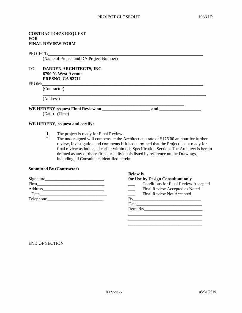
PROJECT CLOSEOUT 1933.ID
CONTRACTOR’S REQUEST FOR FINAL REVIEW FORM
PROJECT:_______________________________________________________________________(Name of Project and DA Project Number)
TO: DARDEN ARCHITECTS, INC.6790 N. West AvenueFRESNO, CA 93711
FROM:__________________________________________________________________________(Contractor)___________________________________________________________________________(Address)
______________________________________________________________________WE HEREBY request Final Review on ______________________ and ___________________.
(Date) (Time)
WE HEREBY, request and certify:
1. The project is ready for Final Review.2. The undersigned will compensate the Architect at a rate of $176.00 an hour for further
review, investigation and comments if it is determined that the Project is not ready for final review as indicated earlier within this Specification Section. The Architect is herein defined as any of those firms or individuals listed by reference on the Drawings, including all Consultants identified herein.
Submitted By (Contractor)Below is
Signature___________________________ for Use by Design Consultant onlyFirm_______________________________ ___ Conditions for Final Review AcceptedAddress____________________________ ___ Final Review Accepted as Noted
Date_______________________________ ___ Final Review Not AcceptedTelephone__________________________ By_______________________________
Date______________________________Remarks_________________________________________________________________________________________________________________________________
END OF SECTION
017720 - 7 05/31/2019

WARRANTIES 1933.ID
SECTION 017836 – WARRANTIES
PART 1 - GENERAL
1.1 SUMMARY
A. In addition to providing all other warranties specified in the Project Manual and without affecting any rights of Owner under State or Federal law, Contractor shall warrant that the Work done under this Project Manual will be free from faulty materials or workmanship and hereby agrees, upon receiving notification from the Owner or his Agent, to immediately remedy, repair or replace, without cost to the Owners and to his entire satisfaction, all defects, damages or imperfections appearing in said work within a period of one (1) year unless specified otherwise, after date of final acceptance by the Owner of all work done under this Project Manual, regardless of whether or not the Owner or persons operating under contract with the Owner partially or wholly occupies any portion of the work prior to acceptance. For work performed after completion, the one (1) year period shall be extended by the period of time between the date of final acceptance by Owner and actual performance of the work. This obligation shall survive acceptance of the work and termination of the Contract.1. Warranties shall be in the form outlined below and shall be submitted in duplicate to the
Contractor and submitted on his own letterhead.
B. Related Sections: The following Project Manual Sections contain requirements that relate to this section:1. ALL DIVISION 00 SPECIFICATION SECTIONS.2. ALL DIVISION 01 SPECIFICATION SECTIONS.3. ALL SPECIFICATION SECTIONS IN THE FACILITY CONSTRUCTION
SUBGROUP.4. ALL SPECIFICATION SECTIONS IN THE FACILITY SERVICES SUBGROUP.5. ALL SPECIFICATION SECTIONS IN THE SITE AND INFRASTRUCTURE
SUBGROUP.
1.2 SUBMITTALS
A. Warranty Form: (following page.)
B.
C.
D.
E.
F.
G. (Contractor's Letterhead)
017836 - 1 05/28/2019
WARRANTIES 1933.ID
H. Project Number: ________
I. Project Name: ______________________________________
J.
K.
L.
WARRANTY FOR
______________________________________________________________________
We hereby warrant and the General Contractor warranties that
______________________________________________________________________
______________________________________________________________________
______________________________________________________________________
has been done in accordance with the Drawings and the Specifications and that the Work as installed will fulfill the requirements of the warranty included in the Project Manual. We agree to repair, replace any or all of our work together with any other adjacent work which may be displaced or damaged by so doing that may prove to be defective in its workmanship or materials within a period of ________________ years from date of acceptance of the above-named without any expense to the Owner, ordinary wear and tear and unusual abuse or neglect excepted. In the event of our failure to comply with above-mentioned conditions within ten (10) days after being notified in writing by the Owner or his agent, we collectively or separately, do hereby authorize the Owner to proceed to have said defects repaired and made good at our expense and we will honor and pay the costs and charges therefor upon demand.
_________________________________(Signature of Subcontractor)
_________________________________(Signature of Contractor)
Date: ____________________
M. Submit 2 copies of all manufacturer's or installer/applicator's warranties and bonds as specified within Division 02 –49.
N. Submit to Architect together with Project Record Documents.
O. Accompany submittals with transmittal letter in duplicate.
017836 - 2 05/28/2019
WARRANTIES 1933.ID
P. When Product Submittals are required, submit copy of warranty with product submittal.
PART 2 - PRODUCTS
NOT APPLICABLE
PART 3 - EXECUTION
NOT APPLICABLE
END OF SECTION
017836 - 3 05/28/2019

SELECTIVE DEMOLITION 1933.ID
SECTION 024919 - SELECTIVE DEMOLITION
PART 1 - GENERAL
1.1 SUMMARY
A. This section includes the following:1. Section includes requirements governing execution of the work including, but not limited
to, the following:a. Demolition and removal of selected portions of building or structure.b. Demolition and removal of selected site elements.c. Salvage of existing items to be reused or recycled.
1) Remove and reinstall door hardware.
B. Related Sections: The following Project Manual Sections contain requirements that relate to this section:1. ALL DIVISION 00 SPECIFICATION SECTIONS2. ALL DIVISION 01 SPECIFICATION SECTIONS3. ALL SPECIFICATION SECTIONS IN THE FACILITY SERVICES SUBGROUP
1.2 REFERENCES
A. Standards:
B. In accordance with the latest edition of the following standards:1. ANSI A10.6 American National Standards Institute
1.3 DEFINITIONS
A. Remove: Detach items from existing site or building (s) and legally dispose or recycle off-site.
B. Remove and Salvage to Owner: Carefully detach from existing site or building (s)), in a manner to prevent damage, and deliver to Owner.
C. Remove and Reinstall: Detach items from existing site or building (s), prepare for reuse, and reinstall where indicated.
D. Existing to Remain: Existing item(s) within project site that are not to be permanently removed and that are not otherwise indicated to be removed, removed and salvaged, or removed and reinstalled.
1.4 SUBMITTALS
A. Submit in accordance with Specification Section - SUBMITTAL PROCEDURES:1. Shop Drawings:
024919 - 1 05/29/2019
SELECTIVE DEMOLITION 1933.ID
a. Proposed Protection Measures - Submit report and drawings that indicates the measures proposed for protecting individuals and property for dust and noise control. 1) Indicate proposed locations and construction of barriers.2) Indicate occupant paths of egress and travel.3) Indicate how long utility services will be interrupted.
b. Salvaged Item Inventory List1) Indicate items to be salvaged and delivered to Owner.
2. Closeout Submittals:a. Existing Warrantiesb. Pre-demolition Photographs
1.5 QUALITY ASSURANCE
A. Regulatory Requirements:1. In accordance with Specification Section - REGULATORY REQUIREMENTS and the
following:a. CARB Materials and equipment used for this project shall comply with the
current applicable regulations of the California Air Resources Board and the Environmental Protection Agency (EPA), in the area where the project is located.
b. CAL/OSHA California Division of Occupational Safety and Health Administration.
c. CF County of Merced, codes and ordinancesd. EPA Environmental Protection Agency
B. Meetings:1. Pre- Demolition………………………………………Schedule prior to the start of work.
a. Coordinate the work with other work being performed. b. Review requirements of work performed by others that rely on substrates exposed
by selective demolition work.c. Identify any potential problems that may impede planned progress and proper
demolition of work.d. Review structural load limitations of existing structure.e. Review areas where existing construction is to remain and requires protection.f. Review demolition waste disposal and material recycling procedures.
2. Progress:………………Scheduled by the Contractor during the performance of the work.a. Review for proper work progress.b. Identify any problems and acceptable corrective measures.c. Identify any measures to maintain or regain project schedule if necessary.
3. Completion:…………Scheduled by the Contractor upon proper completion of the work.a. Inspect and identify any problems.b. Establish method and procedures to maintain protections while progressing to
project completion.
1.6 DELIVERY, STORAGE, AND HANDLING
A. Cleaning, handling, and packing:1. Salvaged Items and Reinstalled Items shall be handled in such a manner as to assure that
they are free from damage.
024919 - 2 05/29/2019
SELECTIVE DEMOLITION 1933.ID
2. Salvaged Items shall be cleaned and packed or cleaned and palleted.3. Reinstalled Items shall be cleaned.
B. Storage and protection1. Salvaged Items and Reinstalled Items shall be stored in a dry, protected area. 2. Salvaged Items and Reinstalled Items shall be stored above ground on level platforms,
six (6) inches above ground, allowing air circulation underneath.3. Cover with protective waterproof covering providing for adequate air circulation and
ventilation.
C. Waste Management and Disposal:1. Disposal of all selective demolition items shall be per Specification Section -
CONSTRUCTION WASTE MANAGEMENT AND DISPOSAL.
1.7 PROJECT CONDITIONS
A. Environmental requirements:1. Dust control - perform site, exterior, and interior work in a manner as to minimize the
spread of dust and flying particles.a. Thoroughly moisten appropriate surfaces as required to prevent dust from being a
nuisance to the occupants, public, and neighbors.2. Noise control - perform work in a manner as to minimize construction noise.
a. When a certain level of noise is unavoidable and is objectionable to the occupants of the adjacent spaces, buildings, or premises, coordinate with Owner and make arrangements to perform such work at the most appropriate time periods of the day.
B. Existing conditions:1. Examine project site and building(s) and compare it with the drawings and specifications.
Thoroughly investigate and verify conditions under which the work is to be performed. No allowance will be made for extra work resulting from negligence or failure to be acquainted with all available information concerning conditions necessary to estimate the difficulty or cost of the work.
2. Conduct work so as not to interfere unnecessarily with adjacent buildings, roads, streets, drives, and walks.a. Do not close or obstruct streets, alleys, walks, or passageways without permission
from authorities having jurisdiction and coordinating same with immediate neighbors whose business operation may be affected.
b. Safety measures shall be taken to insure an uninterrupted flow of traffic around the site as required by local Police and Fire Departments
3. Owner will occupy portions of building immediately adjacent to selective demolition area. Conduct selective demolition so Owner's operations will not be disrupted.
4. Maintain existing utilities indicated to remain in service and protect against damage during selective demolition work.a. Maintain fire-protection facilities in service during the work.
5. Demolition waste becomes the property of the Contractor.6. Storage or sale of removed items on-site is not permitted.7. It is not expected that hazardous materials will be encountered in the Work.
a. If suspected hazardous materials are encountered, do not disturb; immediately notify Architect and Owner.
024919 - 3 05/29/2019
SELECTIVE DEMOLITION 1933.ID
1.8 WARRANTY
A. Existing Warranties:1. Remove, replace, patch, and repair materials and surfaces cut or damaged during
selective demolition, by methods and with materials so as not to void existing warranties. Notify warrantor before proceeding. Existing warranties include the following:a. Roofing system
2. Notify warrantor on completion of selective demolition, and obtain documentation verifying that existing system has been inspected and warranty remains in effect.
PART 2 - PRODUCTS
2.1 MATERIALS
A. Furnish all materials, tools, equipment, facilities, and services as required for performing the selective demolition and removal work.
PART 3 - EXECUTION
3.1 EXAMINATION
A. Verification of conditions:1. Report unacceptable conditions to the Architect. Do not begin work until unacceptable
conditions have been corrected.2. Execution of work under this specification section shall constitute acceptance of existing
conditions.3. Obtain all necessary permits and authorizations by regulatory agencies required to
perform the Work under this Section.4. Verify that utilities have been disconnected and capped before starting selective
demolition operations.5. Verify that rooftop utilities and service piping have been shut-off prior to roof selective
demolition.6. Record existing conditions by use of Pre-demolition Photographs.
a. Inventory and record the condition of items to be salvaged and/or re-installed.
3.2 PREPARATION
A. Coordination:1. Before proceeding, verify plans match existing conditions.2. Review documents of existing construction provided by Owner against existing
conditions. 3. If conflicts are encountered, report it to the Architect. Then prepare recommendation(s)
for correction and submit to Architect for review.4. Coordinate work under this specification section with work specified under other
sections.
024919 - 4 05/29/2019
SELECTIVE DEMOLITION 1933.ID
5. Coordinate any utility and HVAC unit shut-down with owner 48 hours in advance of the anticipated shut-down.a. Do not interrupt utilities and HVAC units serving occupied or used facilities,
except when authorized in writing by the Owner.b. Provide temporary service during interruptions to existing facilities, as may be
required by the Owner to maintain essential services.6. Prior to site selective demolition, review status of trees and shrubs with Architect and
Owner. The Owner may wish to relocate trees or shrubs outside the limits of construction.
7. Prior to roofing selective demolition, coordinate with Owner to shut down air intake equipment and service piping in the vicinity of work.
B. Protection:1. Structure and Property:
a. Provide temporary barricades and other protection required to prevent injury to people and damage to adjacent buildings, landscape, and facilities to remain.
b. All damage inflicted on public and private property and the property of the Owner shall be repaired or restored to the original condition prior to the start of this Work. All repair or replacement work shall be done at no additional cost to the owner.
c. Provide protection to ensure safe passage of people around selective demolition area and to and from occupied portions of building and site.
d. Provide temporary weather protection, during interval between selective demolition of existing construction on exterior surfaces and new construction, to prevent water leakage and other weather damage to building envelope, structure, and interior areas.
e. Protect walls, ceilings, floors, and other existing finish work that are to remain or that are exposed during selective demolition operations.
f. Protect and maintain utility services and mechanical/electrical systems to remain.g. Cover and protect furniture, furnishings, and equipment that have not been
removed.h. Cover all air supply and return ducts to remain before proceeding with demolition
work.i. Cover air intake louvers before proceeding with work that will affect indoor air
quality.j. During roof selective demolition have sufficient and suitable materials on-site to
facilitate rapid installation of temporary protection in the event of unexpected rain.2. Temporary Shoring:
a. Provide and maintain shoring, bracing, and structural supports as required to preserve stability and prevent movement, settlement, or collapse of construction and finishes to remain, and to prevent unexpected or uncontrolled movement or collapse of construction being demolished.1) Strengthen or add new supports when required during progress of selective
demolition.
3.3 APPLICATION
A. General:
024919 - 5 05/29/2019
SELECTIVE DEMOLITION 1933.ID
1. Selective demolition shall include the removal of all components of the existing building and/or site described in the documents to be removed. Unless otherwise specified, the component identified for removal shall include all materials, accessories and fabrications associated with that component.
2. Neatly cut openings and holes plumb, square, and true to dimensions required. Use cutting methods least likely to damage construction to remain or adjoining construction.a. Temporarily cover opening to remain. b. Use hand tools or small power tools designed for sawing or grinding, not
hammering and chopping, to minimize disturbance of adjacent surfaces. 3. Cut or drill from the exposed or finished side into concealed surfaces to avoid marring
existing finished surfaces.4. When removing structural framing members, lower to ground by method suitable to
avoid free fall and to prevent ground impact or dust generation.5. Locate selective demolition equipment and demolished debris so as not to impose
excessive loads on supporting walls, floors, or framing.6. Locate, identify, disconnect, and seal or cap off indicated utility services and
mechanical/electrical systems.7. Removed and Salvaged items:
a. Clean salvaged items.b. Pack or crate items after cleaning. Identify contents of containers.c. Store items in a secure area until delivery to Owner.d. Transport item to Owner's storage area [on-site][off-site][list address].e. Protect items from damage during transport and storage.f. In addition to items indicated elsewhere, salvaged items that the Owner wants to
retain in usable condition are as follows:1) All door hardware2) All unit heater and controls3) All energy management controls4) All security system devices
8. Removed and Reinstalled items:a. Clean and repair items to functional condition adequate for intended reuse.b. Pack or crate items after cleaning and repairing. Identify contents of containers.c. Protect items from damage during transport and storage.d. Reinstall items in locations indicated. Comply with installation requirements for
new materials and equipment. Provide connections, supports, and miscellaneous materials necessary to make item functional for use indicated.
9. Existing Items to Remain:a. Protect construction indicated to remain against damage and soiling during
selective demolition.
B. Site Selective Demolition:1. Utility lines to be abandoned within the construction area shall be removed and stubbed
off outside the limits of construction.2. Maintain existing storm drainage system to remain in functioning condition. Prevent
debris from entering or blocking drains and piping. Use drain plugs specifically for this purpose. Remove drain plugs at the end of each work day.
3. Refer to drawings for trees and shrubs to be removed. Protect certain trees as indicated. a. Remove tops, trunks, and roots of trees and shrubs to a minimum depth of 3 feet or
to a depth required to remove all roots 1/4 inch diameter and larger.b. Chip removed trees, shrubs, and roots.
1) Removed chipped material to recycling station.
024919 - 6 05/29/2019
SELECTIVE DEMOLITION 1933.ID
2) Recycle chipped material into mulch for this project. Refer to Specification Section - LANDSCAPE PLANTING for treatment.
4. Remove debris, concrete, asphalt, and any other obstruction to the extent indicated.5. Remove all:
a. Buried objects which will interfere with the Work.b. Irrigation lines, irrigation risers, and irrigation valves.c. Stand pipes.d. Water wells and pumps.e. Electrical service and power poles.
6. At building pads, site improvements, or trenching, strip topsoil which contains:a. Grass, weeds, and natural vegetation to a minimum depth of [12][18][24] inches.b. Stumps and roots 1/4 inch and larger.
7. Remove non-soil materials from topsoil, including clay lumps, gravel, trash, debris, weeds, roots, other waste materials, and objects more than 1/2 inch in diameter.
8. Stockpile reusable topsoil away from excavation and where work is to proceed.a. Do not stockpile topsoil within drip line of remaining trees.
9. Non-soil materials removed from topsoil shall be separated into like materials and recycled either within the project or removed from the project site to a recycling station.a. Those waste materials that are non-recyclable shall be legally disposed off of the
project site.
3.4 CLEANING
A. Clean in accordance with Specification Section - PROJECT CLOSEOUT:1. Clean any soiled surfaces to remain immediately.2. Existing substrates shall be clean and ready for the installation of any additional
materials.3. Leave site areas level and free of any ruts or debris. Appearance of earth surface shall be
equal to or better than adjacent undisturbed surfaces.
END OF SECTION
024919 - 7 05/29/2019

CONCRETE FORMWORK 1933.ID
SECTION 031101 – CONCRETE FORMWORK
PART 1 - GENERAL
1.1 SUMMARY
A. This Section includes the following:1. Provide all material, labor, equipment and services necessary to completely install all
Concrete Formwork materials, and other related items necessary to complete the Project as indicated by the Contract Documents.
B. Related Sections: The following Project Manual Sections contain requirements that relate to this section:1. ALL DIVISION 00 SPECIFICATION SECTIONS.2. ALL DIVISION 01 SPECIFICATION SECTIONS. 3. 03 15 14 DRILLED ANCHORS4. 03 20 00 REINFORCEMENT5. 03 30 00 CAST-IN-PLACE CONCRETE6. 05 12 00 STEEL AND FABRICATIONS7. ALL SPECIFICATION SECTIONS IN THE FACILITY SERVICES SUBGROUP.8. ALL SPECIFICATION SECTIONS IN THE SITE AND INFRASTRUCTURE
SUBGROUP.
1.2 REFERENCES
A. Standards:1. In accordance with the latest edition of the following standards:
a. ACI American Concrete Institute b. APA The Engineered Wood Association (formerly the American Plywood
Association)c. PS Product Standards of the U.S. Department of Commerce, latest editiond. WCLIB West Coast Lumber Inspection Bureau
1.3 DEFINITIONS
A. Terms used throughout this section.1. Unexposed:
a. "Unexposed to View" for determining what forms to use for an unfinished concrete surface.
2. Exposed:a. "Exposed to View" for determining what forms to use for a finished concrete
surface.
031101 - 1 05/29/2019
CONCRETE FORMWORK 1933.ID
1.4 SUBMITTALS
A. Submit in accordance with Specification Section - SUBMITTAL PROCEDURES:1. Product Data.
a. Forming materials.b. Tie rods and spreaders.c. Formwork for exposed concrete.d. Form coatings and release agents.
2. Shop Drawings:a. The Contractor shall submit drawings showing the proposed form tie locations for
exposed form indentations. 3. Samples.
a. Form liners for specific finished concrete surfaces.4. Quality Assurance/Control Submittals:
a. Manufacturer's written Instructions:1) Instructions for specific form liner manufacturer indicated.
5. Closeout Submittals:a. Record Documents in accordance with Specification Section – PROJECT
DOCUMENTS.
1.5 QUALITY ASSURANCE
A. Qualifications:1. Installer Qualifications:
a. Engage an experienced Installer who has successfully completed three (3) projects of similar scope and size to that indicated for this Project.
2. Manufacturer/Supplier Qualifications:a. Firm experienced in successfully producing/supplying products similar to that
indicated for this Project, with sufficient production/supply capacity to produce/supply required units without causing delay in the Work.
B. Regulatory Requirements:1. In accordance with Specification Section - REGULATORY REQUIREMENTS, and the
following:a. CARB Materials and equipment used for this Project shall comply with the
current applicable regulations of the California Air Resources Board (CARB)and the Environmental Protection Agency (EPA), in the area where the project is located.
1.6 WARRANTY
A. Contractor's General Warranty:1. In accordance with Specification Section - WARRANTIES.
B. Manufacturer's Warranty:1. In accordance with manufacturer's written standard warranty:
a. Warranty Period One (1) Year.
031101 - 2 05/29/2019
CONCRETE FORMWORK 1933.ID
C. Installer's Warranty:1. In accordance with the terms of the Specification Section - WARRANTIES.
a. Warranty Period One (1) Year.
PART 2 - PRODUCTS
2.1 MANUFACTURERS
A. These products listed herein establish the size, pattern, color range and function selected by the Architect for this Project. Manufacturers that are listed as acceptable alternative manufacturers and substitutions must still comply with the requirements of this project and the products listed in order to be approved as an equivalent during the Submittal Process. If the acceptable alternative manufacturers listed or substitutions are not approved during the Submittal Process due to non-compliance with the contract documents, then the Contractor shall submit product specified. 1. Specified product manufacturer:
a. MDO Plywood SIMPSON TIMBER PRODUCTS.b. HDO Plywood SIMPSON TIMBER PRODUCTS.
2. Specified product accessories:a. Chamfer Strips MEADOW / BURKE COMPANY.b. Cement Compound Plugs MEADOW / BURKE COMPANY.c. Double Sided Foam Tape 3M COMPANY.d. Rustication Strips MEADOW / BURKE COMPANY.e. Spreaders and Ties MEADOW / BURKE COMPANY.
B. Products from other manufacturers not listed must submit in accordance with Specification Section - SUBSTITUTION PROCEDURES.
2.2 MATERIALS
A. Unexposed finish forms:1. Provide plywood, lumber, or another acceptable material.
a. Lumber shall be dressed on at least two edges and one side for tight fit, complying with WCLIB Standard Grading and Dressing Rules #17, for Douglas Fir Form Lumber.
b. When plywood is used, provide panels complying with PS1, B-B (Concrete Form) Plywood, Group 1, EXT-APA mill-oiled and edge-sealed, with each piece bearing legible inspection trademark.
B. Exposed finish forms:1. Provide plywood panel type materials to provide continuous, straight, smooth, exposed
surfaces. Furnish in largest practical sizes to minimize number of joints and to conform to joint system shown on the drawings.
031101 - 3 05/29/2019
CONCRETE FORMWORK 1933.ID
a. Single Pour Forms: Provide liner panels that are complying with PS1, MDO Plywood, B-B, Group 1, EXT-APA, mill-oiled, edge-sealed, with each piece bearing legible inspection trademark, which are limited to "single-pour use" forms, that are manufactured by SIMPSON TIMBER PRODUCTS, or approved equivalent.
b. Multiple Pour Forms: Provide HDO Plywood "Multipour" liner panels, which are limited to "double-pour use" forms, that are manufactured by SIMPSON TIMBER PRODUCTS, or approved equivalent.
2.3 ACCESSORIES
A. Cement Compound Plugs:1. Provide gray colored cement compound plugs ("SnaPlug" by MEADOW / BURKE, or
approved equivalent) in highly visible concrete surface areas.a. Provide "flush type" in cone holes of size appropriate to the hole size created by
tie-holes.2. Provide a waterproof neoprene adhesive ("SnaPlug Bonder" by MEADOW / BURKE, or
approved equivalent), resistant to weather aging and bacterial growth, for adhering cement compound plugs into cone holes.
B. Chamfer Strips:1. Provide wood chamfer strips free of knots, for forming edges of cast-in-place concrete.
C. Double Sided Foam Tape: Provide "Scotch" double sided, high density, pressure sensitive adhesive, foam tape as manufactured by The Tape Divison of 3M PRODUCTS, INC., or approved equivalent.
D. Form release agent:1. Provide commercial formulation form release agent with a maximum volatile organic
compounds (VOC's) in compliance with the CARB in the area where the project is located, that will not bond with, stain, or adversely affect concrete surfaces and will not impair subsequent treatments of concrete surfaces.
2. Provide form liner manufacturer's form release agent when a particular form liner is used to maintain compatibility with form release agent and the form liners used for this project.
E. Rustication Strips:1. Provide wood rustication strips free of knots, for forming straight continuous reveals
(either vertically or horizontally) and PVC rustication strips as manufactured by MEADOW / BURKE, for forming curved continuous reveals (either vertically or horizontally).
F. Spreaders and ties for loose plywood forming:1. Spreader Ties: Use metal spreaders and ties for surfaces to be sacked. Use type that will
give positive tying and accurate spreading for accurate sizing of cast walls or forms. Snap type shall leave no metal closer than 1-1/2 inches from exposed surface of concrete and have spreader cones no larger than 1 inch diameter.
G. Nailer Strip:
031101 - 4 05/29/2019
CONCRETE FORMWORK 1933.ID
1. Provide decay resistant pressure treated wood nailer strips of sizes and locations indicated on the drawings. a. For roof systems, provide compatible materials with the roof system manufacturer's
applications. b. Provide fire retardant pressure treated wood nailer strips when the roof assembly
requires a Class A rating. 2. All pressure treated wood (decay or fire-retardant) shall be in accordance with the
applicable standards of the AWPA as referenced in the Specification Section - ROUGH CARPENTRY.
PART 3 - EXECUTION
3.1 PREPARATION
A. Surface preparation:1. Consult with other Trades relative to required openings, and items to be imbedded in
concrete (i.e., piping, conduit, hangers, reglets, anchors, inserts, sleeves, etc.). Coordinate work specified under other sections to ensure proper, adequate interfacing between trades, for openings, chases, blockouts, and other required interfacing items.
3.2 ERECTION
A. All formwork shall be:1. Designed and constructed in accordance with ACI Standard 347 "Recommended Practice
for Concrete Formwork".a. Follow ACI 303R "Guide to Cast-In-Place Architectural Concrete" for further
recommendations in design and use of Patterned Form Liners.2. Construct to size, shape, alignment, elevation and position of all concrete elements.
a. Provide for openings, offsets, sinkages, keyways, recesses, moldings, rustications, reglets, chamfers, blocking, screeds, bulkheads, anchorages, inserts, and other features required in the work. Use selected materials to obtain required finishes.
b. Orient circular fiberglass forms so that the seam is always facing the nearest adjacent wall, or an obscure side not highly visible. Contact the Architect for conditions not easily determined.
3. Properly separate and securely tie with Spreaders and Ties to maintain proper shape. Wood spreaders shall not be allowed to remain in concrete work.a. Use "Penta-Ties" where indicated on the drawings. Glue in cement compound
plugs.4. Brace, support and center sufficiently to carry without excessive deflection all live and
dead loads imposed during construction and placement of concrete, and to insure safety to workers and passersby.a. Block adjoining permanent pan units left in place to prevent lateral deflection of
forms while placing concrete.5. Properly construct to eliminate all open joints or discontinuous surfaces.
a. Solidly butt joints with double sided foam tape, apply silicone sealant at concrete face, and provide backup at joints to prevent cement paste or mortar from leaking.
B. All joints shall be:
031101 - 5 05/29/2019
CONCRETE FORMWORK 1933.ID
1. Uniform and backed by 2 inch material.2. Continuous and level or plumb.3. Sufficiently tight (with double sided foam tape and silicone sealant) to prevent leakage of
cement paste.a. Locate joints of formwork whenever possible at rustication joints.
4. Subject to Architect's approval.
3.3 INSTALLATION
A. General: Design, engineer, erect, support, brace, and maintain formwork to support vertical, lateral, static, and dynamic loads that might be applied until concrete structure can support such loads. Construct formwork so concrete members and structures are of correct size, shape, alignment, elevation, and position.1. Access Openings: Shall be provided in forms for cleaning and inspection of forms and
reinforcement.a. In Wall Forms: Provide openings for each pour, composed of a form section held
out until inside of each formed cavity has been cleaned, so that no "access hole" is visible in the finished concrete surface.
2. Architectural Concrete elements shall be formed with MDO (or HDO) form plywood where face uniformity is required such as on signs, plaques, kiosks, and landscape elements.
3. Side forms at unexposed footings may be omitted if excavation stands without caving.a. Make footing trench two (2) inches wider than width of concrete footing indicated
on the drawings, when earth is used as a form. b. Cut trenches true and straight. c. Make side cuts neat and plumb. d. Bottom of trenches shall be level with reasonably sharp corners.
4. Formwork above grade (stairs, curbs, exposed faces of concrete foundations, etc.) shall be:a. Plywood type as specified treated with Sealer.b. Constructed with plumb and level joints.c. Separated with removable or snap type Spreaders and Ties. Do not use wire ties.
5. Unintentional indentations in the surface of the concrete left after removal of spreaders and ties shall be filled and sacked unless the architect's approval is given to do otherwise.a. Install Cement Compound Plugs where exposed form tie indentations occur.
6. Sleeves, anchors and bolts, angles, supports, ties and other materials in connection with concrete construction shall be secured in position before the concrete is placed.
3.4 CONSTRUCTION
A. Special Techniques – Form Removal and Reuse of Forms:1. All forms shall be completely removed.2. Time of Removal shall be in accordance with ACI 301 "Specifications for Structural
Concrete", which requires concrete to reach its specified compressive strength. Variations to the time of removal are listed below subject to the concrete reaching its specified compressive strength:a. Dependent on weather conditions.
031101 - 6 05/29/2019
CONCRETE FORMWORK 1933.ID
1) Due to excessive cold weather for a long duration of days, and subject to the Architect's approval, the time for removal may be extended if deemed necessary.
b. Dependent on cylinder test results.c. Dependent on recommendations of additive manufacturer when additives are
admitted to the mix.d. Typically (verify with three statements above before initiating the following):
1) Foundation Side Forms: Five (5) days after concrete is poured.2) Wall Forms: Ten (10) day after concrete is poured.3) Slab Forms:
a) Twenty-One (21) days after concrete is pourede. Remove forms in a manner that will not harm concrete. Do not hammer or pry
against concrete.3. Nails, tie wires and form ties shall be cut off flush with face of concrete.4. Snap type spreaders to be snapped off inside the wall surface.5. Clean and repair surfaces of forms to be reused in the work. Split, frayed, delaminated, or
otherwise damaged form-facing material will not be acceptable for exposed surfaces. Apply new form-release compound as specified for new formwork.
6. When forms are extended for successive concrete placement, thoroughly clean surfaces, remove fins and laitance, and tighten forms to close joints. Align and secure joint to avoid offsets. Do not use patched forms for exposed concrete surfaces except as acceptable to the Architect.
B. Site Tolerances:1. Maintain formwork construction tolerances and surface irregularities complying with the
following ACI 347 "Guide to Formwork for Concrete" limits:a. Provide Class A tolerances (permitted irregularities are 1/8" in 10' for both gradual
and abrupt) for all concrete surfaces exposed to view, or surfaces that will receive additional applied finishes.
2. Concrete work out of alignment, or level or plumb exceeding the allowable tolerance will be cause for rejection of the whole work affected. Such work shall be removed and replaced as directed by Architect with no additional cost to Owner.
3.5 CLEANING
A. Thoroughly clean forms and adjacent surfaces to receive concrete. Remove chips, wood, sawdust, dirt, or other debris just before placing concrete. Retighten forms and bracing before placing concrete, as required, to prevent leakage of cement paste and maintain alignment.
B. Remove all wood used for formwork from trenches. No wood shall be left buried in the earth.
C. Final cleaning shall be in accordance with Specification Section – PROJECT CLOSEOUT.
END OF SECTION
031101 - 7 05/29/2019

DRILLED ANCHORS 1933.ID
SECTION 031514 – DRILLED ANCHORS
PART 1 - GENERAL
1.1 SUMMARY
A. This Section includes the following:1. Provide all Drilled Anchor materials, labor, equipment and services necessary for
Expansion, and Adhesive Anchors in Concrete, and Concrete Masonry Units, and related items necessary to complete the Project as indicated by the Contract Documents unless otherwise specifically excluded.
B. Related Sections: The following Project Manual Sections contain requirements that relate to this section:1. ALL DIVISION 00 SPECIFICATION SECTIONS.2. ALL DIVISION 01 SPECIFICATION SECTIONS. 3. 03 11 01 CONCRETE FORMWORK4. 03 20 00 REINFORCEMENT5. 03 30 00 CAST-IN-PLACE CONCRETE6. 05 12 00 STEEL AND FABRICATIONS7. 09 22 16 METAL FRAMING8. ALL SPECIFICATION SECTIONS IN THE FACILITY SERVICES SUBGROUP.9. ALL SPECIFICATION SECTIONS IN THE SITE AND INFRASTRUCTURE
SUBGROUP.
1.2 SUBMITTALS
A. Submit in accordance with Specification Section - SUBMITTAL PROCEDURES:1. Product Data.
a. Submit manufacturer's product data for all expansion and adhesive anchors to be used in this project.1) Submit current ICC Evaluation Services research or evaluation reports
evidencing maximum allowable shear and withdrawal load data.2. Quality Assurance / Control Submittals:
a. Test Reports: Submit to AHJ, copy to Project Inspector and Contractor.1) Tension Testing as required.
1.3 QUALITY ASSURANCE
A. Single Source Responsibility: 1. To ensure consistent quality of anchorage, obtain drilled anchors from a single
manufacturer.2. To ensure consistency of anchorage, obtain adhesive for anchorage from a single
manufacturer.
031514 - 1 05/29/2019
DRILLED ANCHORS 1933.ID
B. Manufacturer Qualifications: Provide drilled and adhesive anchors from a manufacturer that can demonstrate ICC approvals that are current and acceptable to review by the AHJ.
C. In accordance with Specification Section - REGULATORY REQUIREMENTS and the following:1. ICC International Code Council2. IR Interpretation of Regulations
D. Job Testing: For verifying satisfactory installation workmanship, an independent laboratory will perform proof load tests of drilled anchors acting in tension or shear in the presence of the Project Inspector.1. When drilled-in expansion-type anchors or other post-installed anchors acceptable to the
enforcement agency are used in lieu of cast-in-place bolts, the allowable shear and tension values and installation verification test loads shall be acceptable to the enforcement agency.
1.4 DELIVERY, STORAGE, AND HANDLING
A. Deliver products in original, unopened packages with manufacturer's labels identifying products legible and intact.
B. Store materials inside, under cover and in a manner to keep them dry, protected from the weather, surface contamination, corrosion, damage from construction traffic and other causes.
1.5 WARRANTY
A. Contractor's General Warranty:1. In accordance with Specification Section - WARRANTIES.
B. Manufacturer's Warranty:1. In accordance with manufacturer's written standard warranty:
a. Warranty Period One (1) Year.
C. Installer's Warranty:1. In accordance with the terms of the Specification Section - WARRANTIES.
a. Warranty Period One (1) Year.
031514 - 2 05/29/2019
DRILLED ANCHORS 1933.ID
PART 2 - PRODUCTS
2.1 MANUFACTURERS
A. These products listed herein establish the size, pattern, color range and function selected by the Architect for this Project. Manufacturers that are listed as acceptable alternative manufacturers and substitutions must still comply with the requirements of this project and the products listed in order to be approved as an equivalent during the Submittal Process. If the acceptable alternative manufacturers listed or substitutions are not approved during the Submittal Process due to non-compliance with the contract documents, then the Contractor shall submit product specified. 1. Specified Product Manufacturer:
a. Expansion Anchors:1) HILTI INC.2) Acceptable Alternative Manufacturers:
a) ITW RAMSET/RED HEAD.b) SIMPSON.c) WEJ-IT.
b. Adhesive Anchors:1) HILTI INC.2) Acceptable Alternative Manufacturers:
a) ITW RAMSET/RED HEAD.b) SIMPSON.c) WEJ-IT.
B. Products from other manufacturers not listed must submit in accordance with Specification Section - SUBSTITUTION PROCEDURES.
2.2 MATERIALS
A. Provide manufacturers standard drilled anchors (expansion or adhesive) for installation into Concrete or Concrete Masonry Units unless noted otherwise.1. Metal Finishes (corrosion resistant):
a. Zinc Plated Carbon Steel b. Stainless Steel.
B. Expansion Anchors:1. Wedge Anchors: The WEDGE category features a small split expansion ring installed on
a tapered (integral cone) part of the stud at the bottom. As the nut is tightened, withdrawing the stud portion from the hole, the expansion ring engages the concrete and is further expanded on the tapered part of the stud.
031514 - 3 05/29/2019
DRILLED ANCHORS 1933.ID
2. Sleeve Anchors: The SLEEVE category is similar to the wedge except a large expansion sleeve is used instead of a small expansion ring. The outside of the sleeve defines the anchor diameter with the threaded stud being of a smaller diameter since it fits inside the sleeve. The stud has an integral cone expander at the bottom similar to the wedge category. The expansion mechanism is similar to the wedge category except the top of the sleeve is normally in contact with the nut/washer and is initially forced down over the cone expander as the anchor is tightened. As the sleeve is expanded, it engages the concrete and continues to expand as the wedge anchor.
3. Shell Anchors: The SHELL category has the most variations, but all use a tapered cone expander, either internal or external, to expand the shell of the anchor against the hole. The anchor is either hammered down over an external expander or a special tool is used to drive an internal expander further into the anchor.
C. Adhesive Anchors which chemically bonds Steel Rods or Deformed Steel Reinforcement Dowels to concrete or masonry elements:1. Threaded Steel Rods with minimum yield strength of 36 ksi and complying with ASTM
A36 "Specification for Carbon Structural Steel", or ASTM A193 "Specification for Alloy-Steel and Stainless Steel Building Materials for High Temperature or High Pressure Service and Other Special Purpose Applications", Grade B7.
2. Deformed Steel Reinforcement Dowels shall be a minimum of Grade 60 and comply with ASTM A615 "Specification for Deformed and Plain Carbon-Steel Bars for Concrete Reinforcement" or ASTM A706 "Specification for Low-Alloy Steel Deformed and Plain Bars for Concrete Reinforcement".
3. Adhesives, consisting of two primary components that are stored separately, and having a mixing nozzle provided by the manufacturer combining the components prior to placing in the holes.
4. Long term durability and stability of the adhesive anchor material and its resistance to loss of strength and chemical change at elevated temperatures shall be established to the satisfaction of the enforcement agency.
PART 3 - EXECUTION
3.1 PREPARATION
A. Coordination:1. Coordinate and provide anchors and installation instructions from the manufacturer for
items to be embedded in Concrete or Concrete Masonry Unit construction. Manufacturer's written installation instructions shall be available on the project site.
3.2 INSTALLATION
A. Fastening to In-Place Construction: Provide anchorage devices where necessary for securing designated items indicated on the drawings, or as necessary for a complete and proper job to in-place construction.1. Install the anchors in accordance with the requirements given in the ICC Evaluations
Services Report recommendations for the specific anchor used.
031514 - 4 05/29/2019
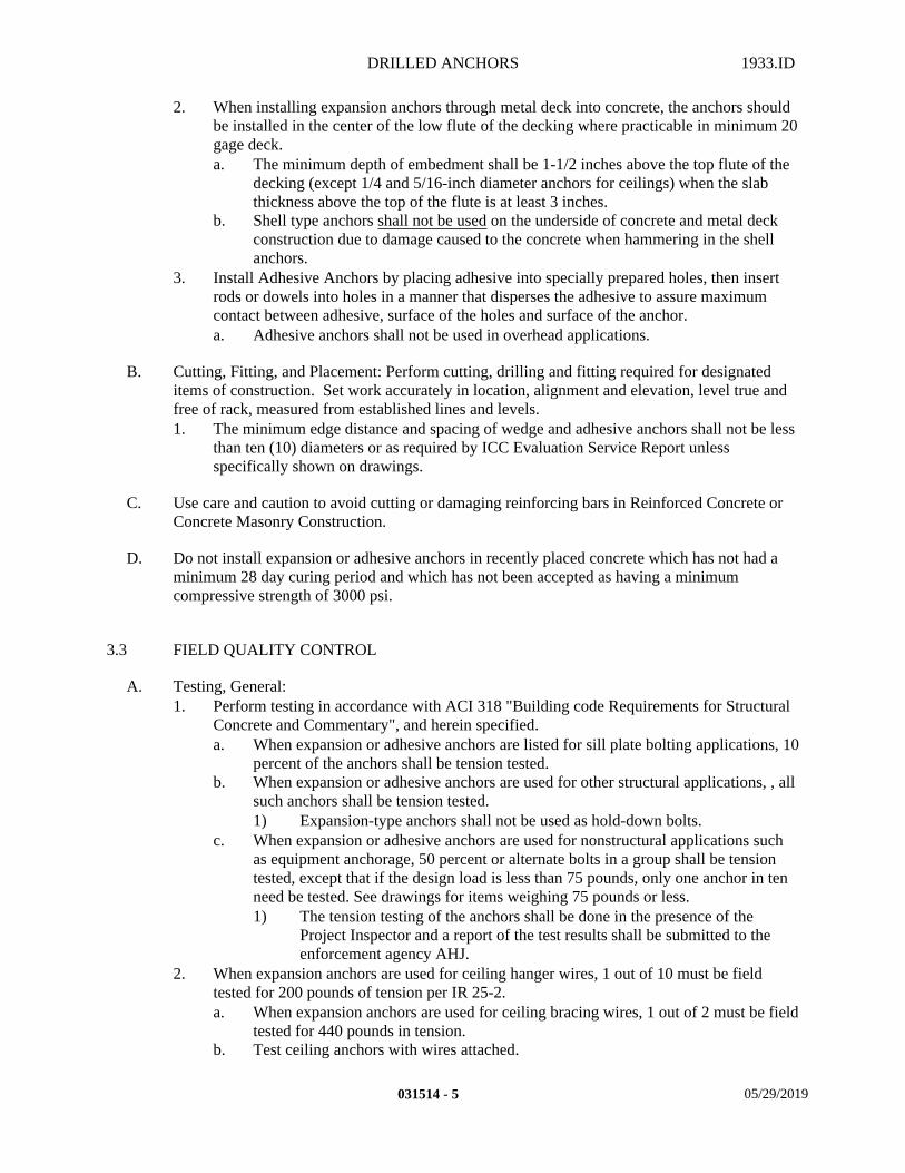
DRILLED ANCHORS 1933.ID
2. When installing expansion anchors through metal deck into concrete, the anchors should be installed in the center of the low flute of the decking where practicable in minimum 20 gage deck.a. The minimum depth of embedment shall be 1-1/2 inches above the top flute of the
decking (except 1/4 and 5/16-inch diameter anchors for ceilings) when the slab thickness above the top of the flute is at least 3 inches.
b. Shell type anchors shall not be used on the underside of concrete and metal deck construction due to damage caused to the concrete when hammering in the shell anchors.
3. Install Adhesive Anchors by placing adhesive into specially prepared holes, then insert rods or dowels into holes in a manner that disperses the adhesive to assure maximum contact between adhesive, surface of the holes and surface of the anchor.a. Adhesive anchors shall not be used in overhead applications.
B. Cutting, Fitting, and Placement: Perform cutting, drilling and fitting required for designated items of construction. Set work accurately in location, alignment and elevation, level true and free of rack, measured from established lines and levels.1. The minimum edge distance and spacing of wedge and adhesive anchors shall not be less
than ten (10) diameters or as required by ICC Evaluation Service Report unless specifically shown on drawings.
C. Use care and caution to avoid cutting or damaging reinforcing bars in Reinforced Concrete or Concrete Masonry Construction.
D. Do not install expansion or adhesive anchors in recently placed concrete which has not had a minimum 28 day curing period and which has not been accepted as having a minimum compressive strength of 3000 psi.
3.3 FIELD QUALITY CONTROL
A. Testing, General:1. Perform testing in accordance with ACI 318 "Building code Requirements for Structural
Concrete and Commentary", and herein specified.a. When expansion or adhesive anchors are listed for sill plate bolting applications, 10
percent of the anchors shall be tension tested.b. When expansion or adhesive anchors are used for other structural applications, , all
such anchors shall be tension tested.1) Expansion-type anchors shall not be used as hold-down bolts.
c. When expansion or adhesive anchors are used for nonstructural applications such as equipment anchorage, 50 percent or alternate bolts in a group shall be tension tested, except that if the design load is less than 75 pounds, only one anchor in ten need be tested. See drawings for items weighing 75 pounds or less.1) The tension testing of the anchors shall be done in the presence of the
Project Inspector and a report of the test results shall be submitted to the enforcement agency AHJ.
2. When expansion anchors are used for ceiling hanger wires, 1 out of 10 must be field tested for 200 pounds of tension per IR 25-2. a. When expansion anchors are used for ceiling bracing wires, 1 out of 2 must be field
tested for 440 pounds in tension. b. Test ceiling anchors with wires attached.
031514 - 5 05/29/2019
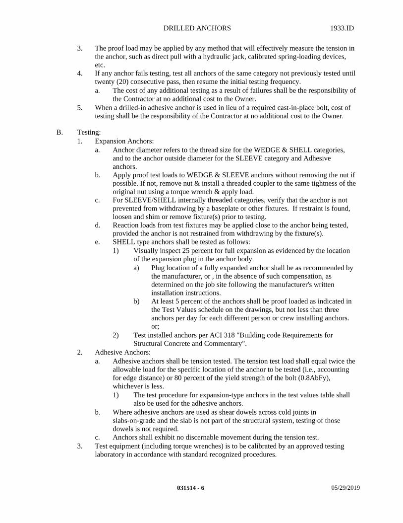
DRILLED ANCHORS 1933.ID
3. The proof load may be applied by any method that will effectively measure the tension in the anchor, such as direct pull with a hydraulic jack, calibrated spring-loading devices, etc.
4. If any anchor fails testing, test all anchors of the same category not previously tested until twenty (20) consecutive pass, then resume the initial testing frequency.a. The cost of any additional testing as a result of failures shall be the responsibility of
the Contractor at no additional cost to the Owner.5. When a drilled-in adhesive anchor is used in lieu of a required cast-in-place bolt, cost of
testing shall be the responsibility of the Contractor at no additional cost to the Owner.
B. Testing:1. Expansion Anchors:
a. Anchor diameter refers to the thread size for the WEDGE & SHELL categories, and to the anchor outside diameter for the SLEEVE category and Adhesive anchors.
b. Apply proof test loads to WEDGE & SLEEVE anchors without removing the nut if possible. If not, remove nut & install a threaded coupler to the same tightness of the original nut using a torque wrench & apply load.
c. For SLEEVE/SHELL internally threaded categories, verify that the anchor is not prevented from withdrawing by a baseplate or other fixtures. If restraint is found, loosen and shim or remove fixture(s) prior to testing.
d. Reaction loads from test fixtures may be applied close to the anchor being tested, provided the anchor is not restrained from withdrawing by the fixture(s).
e. SHELL type anchors shall be tested as follows:1) Visually inspect 25 percent for full expansion as evidenced by the location
of the expansion plug in the anchor body.a) Plug location of a fully expanded anchor shall be as recommended by
the manufacturer, or , in the absence of such compensation, as determined on the job site following the manufacturer's written installation instructions.
b) At least 5 percent of the anchors shall be proof loaded as indicated in the Test Values schedule on the drawings, but not less than three anchors per day for each different person or crew installing anchors. or;
2) Test installed anchors per ACI 318 "Building code Requirements for Structural Concrete and Commentary".
2. Adhesive Anchors:a. Adhesive anchors shall be tension tested. The tension test load shall equal twice the
allowable load for the specific location of the anchor to be tested (i.e., accounting for edge distance) or 80 percent of the yield strength of the bolt (0.8AbFy), whichever is less.1) The test procedure for expansion-type anchors in the test values table shall
also be used for the adhesive anchors.b. Where adhesive anchors are used as shear dowels across cold joints in
slabs-on-grade and the slab is not part of the structural system, testing of those dowels is not required.
c. Anchors shall exhibit no discernable movement during the tension test. 3. Test equipment (including torque wrenches) is to be calibrated by an approved testing
laboratory in accordance with standard recognized procedures.
031514 - 6 05/29/2019
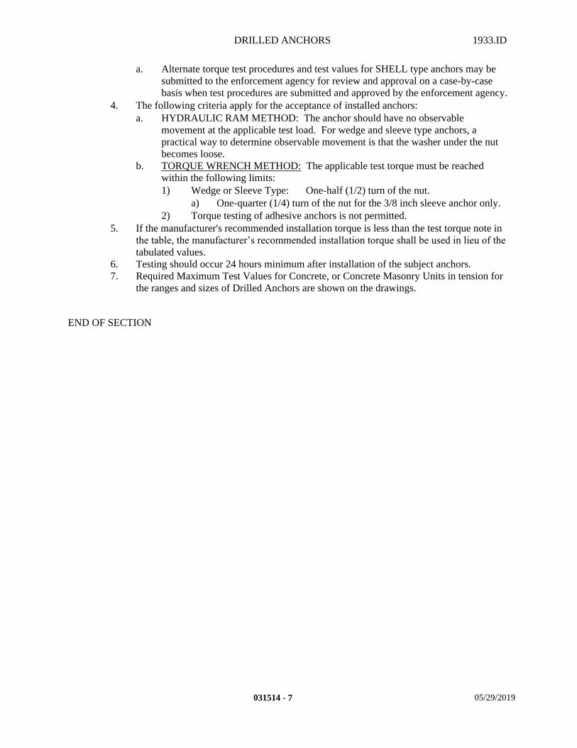
DRILLED ANCHORS 1933.ID
a. Alternate torque test procedures and test values for SHELL type anchors may be submitted to the enforcement agency for review and approval on a case-by-case basis when test procedures are submitted and approved by the enforcement agency.
4. The following criteria apply for the acceptance of installed anchors:a. HYDRAULIC RAM METHOD: The anchor should have no observable
movement at the applicable test load. For wedge and sleeve type anchors, a practical way to determine observable movement is that the washer under the nut becomes loose.
b. TORQUE WRENCH METHOD: The applicable test torque must be reached within the following limits:1) Wedge or Sleeve Type: One-half (1/2) turn of the nut.
a) One-quarter (1/4) turn of the nut for the 3/8 inch sleeve anchor only.2) Torque testing of adhesive anchors is not permitted.
5. If the manufacturer's recommended installation torque is less than the test torque note in the table, the manufacturer’s recommended installation torque shall be used in lieu of the tabulated values.
6. Testing should occur 24 hours minimum after installation of the subject anchors.7. Required Maximum Test Values for Concrete, or Concrete Masonry Units in tension for
the ranges and sizes of Drilled Anchors are shown on the drawings.
END OF SECTION
031514 - 7 05/29/2019

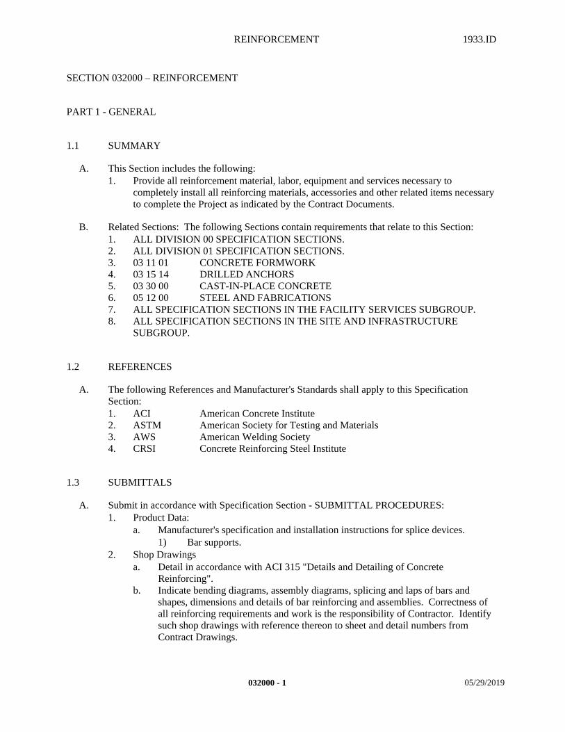
REINFORCEMENT 1933.ID
SECTION 032000 – REINFORCEMENT
PART 1 - GENERAL
1.1 SUMMARY
A. This Section includes the following:1. Provide all reinforcement material, labor, equipment and services necessary to
completely install all reinforcing materials, accessories and other related items necessary to complete the Project as indicated by the Contract Documents.
B. Related Sections: The following Sections contain requirements that relate to this Section:1. ALL DIVISION 00 SPECIFICATION SECTIONS.2. ALL DIVISION 01 SPECIFICATION SECTIONS. 3. 03 11 01 CONCRETE FORMWORK4. 03 15 14 DRILLED ANCHORS5. 03 30 00 CAST-IN-PLACE CONCRETE6. 05 12 00 STEEL AND FABRICATIONS7. ALL SPECIFICATION SECTIONS IN THE FACILITY SERVICES SUBGROUP.8. ALL SPECIFICATION SECTIONS IN THE SITE AND INFRASTRUCTURE
SUBGROUP.
1.2 REFERENCES
A. The following References and Manufacturer's Standards shall apply to this Specification Section:1. ACI American Concrete Institute2. ASTM American Society for Testing and Materials3. AWS American Welding Society4. CRSI Concrete Reinforcing Steel Institute
1.3 SUBMITTALS
A. Submit in accordance with Specification Section - SUBMITTAL PROCEDURES:1. Product Data:
a. Manufacturer's specification and installation instructions for splice devices.1) Bar supports.
2. Shop Drawingsa. Detail in accordance with ACI 315 "Details and Detailing of Concrete
Reinforcing".b. Indicate bending diagrams, assembly diagrams, splicing and laps of bars and
shapes, dimensions and details of bar reinforcing and assemblies. Correctness of all reinforcing requirements and work is the responsibility of Contractor. Identify such shop drawings with reference thereon to sheet and detail numbers from Contract Drawings.
032000 - 1 05/29/2019

REINFORCEMENT 1933.ID
1) Do not use scaled dimensions from Contract Drawings in determining the lengths of reinforcing bars.
2) No reinforcing steel shall be fabricated without approved shop drawings.3) One of the required submittal copies shall be reproducible transparency.4) Any deviations from the contract documents must be clearly indicated as a
deviation on the shop drawings.5) Areas of high congestion, including member joints and embed locations
shall be fully detailed to verify clearances and assembly parameters and coordination with other trades.
c. Certificates of Compliance with specified standards:1) Reinforcing Bars.2) Welded wire fabric.3) Welding electrodes.
3. Samplesa. Only as requested by Architect.
4. Quality Assurance/Control Submittals:a. Test Reports – Testing Laboratory shall submit to DSA/SSS, Project Inspector,
Architect, Structural Engineer and the Contractor one (1) copy of each report showing results of test. 1) Certified mill test reports of supplied reinforcing indicating chemical and
physical analysis. Tensile and bend tests shall be performed by the mill in accordance with ASTM A615 "Specification for Deformed and Plain Carbon-Steel Bars for Structural Concrete".
2) Testing Laboratory reinforcement tests in accordance with CBC Table 1705A.2.1, CBC Section 1913A, and the provisions of Specification Section – TESTING LABORATORY SERVICES.
3) Owner will pay for tests of samples taken from identified bundles accompanied by mill analysis.
b. Certificates of Compliance with specified standards:1) Reinforcing bars.2) Welded wire fabric.3) Welding electrodes.4) Welder's Certification.
5. Closeout Submittals:a. Project Record Documents in accordance with Specification Section - PROJECT
DOCUMENTS.b. Warranty.
1.4 QUALITY ASSURANCE
A. Qualifications:1. Installer Qualifications:
a. Installation shall be done only by an installation firm normally engaged in this business. All work shall be performed by qualified mechanics working under an experienced supervisor.
2. Welding Qualifications:a. Welding procedures, welding operators and welders shall be qualified in
accordance with AWS D1.4 – "Structural Welding Code Reinforcing Steel".
032000 - 2 05/29/2019
REINFORCEMENT 1933.ID
b. Welders shall be recently qualified by Test as prescribed in AWS "Standard Qualifications Procedure".1) Welders whose work fails to pass inspection shall be re-qualified before
performing further welding.3. Manufacturer/Supplier Qualifications:
a. Acceptable Manufacturers/Suppliers shall be regularly engaged in the manufacture of steel bar and wire fabric reinforcing.
4. Testing Laboratory will be approved by DSA/SSS, and selected by the Architect and the Owner.
B. Regulatory Requirements:1. In accordance with Specification Section – REGULATORY REQUIREMENTS and the
following:a. CARB Materials and equipment used for this Project shall comply with the
current applicable regulations of the California Air Resources Board (CARB)and the Environmental Protection Agency (EPA), in the area where the project is located.
C. General:1. Reinforcement work shall conform to ACI 301 "Specifications for Structural Concrete for
Buildings", and CBC Section 1905A and 1913A as minimum standards.
1.5 DELIVERY, STORAGE, AND HANDLING
A. Packing, shipping, handling, and unloading: 1. Deliver reinforcement to Project plainly tagged, completely fabricated and ready to set.
B. Storage and protection: 1. Store reinforcement above the ground surface on platforms, skids or other supports,
protected form dirt, rust, or other substances which will prevent bonding to the concrete.2. Use all necessary care to maintain identification after bundles are taken apart.
1.6 WARRANTY
A. Contractor's General Warranty:1. In accordance with Specification Section - WARRANTIES.
B. Manufacturer's Warranty:1. In accordance with manufacturer's written standard warranty:
a. Warranty Period One (1) Year.
C. Installer's Warranty:1. In accordance with the terms of the Specification Section - WARRANTIES.
a. Warranty Period One (1) Year.
032000 - 3 05/29/2019
REINFORCEMENT 1933.ID
PART 2 - PRODUCTS
2.1 MATERIALS
A. Deformed Bars: In accordance with ASTM A 706 "Low Alloy Steel Deformed Bars for Concrete Reinforcement" and ASTM A 615 "Specification for Deformed and Plain Carbon-Steel Bars for Concrete Reinforcement", Grade as indicated on the structural drawings.
B. Tie Wire: In accordance with ASTM A 82 "Cold Drawn Wire for Concrete Reinforcement", plain, cold-drawn steel.
C. Welded Wire Fabric: In accordance with ASTM A 185 "Welded Steel Wire Fabric for Concrete Reinforcement".
D. Steel Dowels: Same grade as bars to which dowels are connected.
2.2 ACCESSORIES
A. Supports for Reinforcement: Provide bolsters, chairs, spacers, and other devices for spacing, supporting, and fastening, deformed bars and welded wire fabric in place. Use wire bar-type supports complying with CRSI specifications.1. Supports and spacing of spacers per standards set forth by CRSI/WCRSI Manual of
Standard Practice.2. For slabs-on-grade, use supports with sand plates or horizontal runners where base
material will not support chair legs.3. For exposed-to-view concrete surfaces, where legs of supports are in contact with forms,
provide supports with legs that are protected by plastic [color to match adjacent concrete surfaces] in accordance with CRSI Class I, or stainless steel in accordance with CRSI, Class II.
B. Welding Electrodes: As per AWS D1.4 "Structural Welding Code for Reinforcing Steel".
C. Mechanical Couplers: Mechanical Couplers shall develop 125 percent of the specified yield strength of the bars, and shall comply with ACI 318 "Building Code Requirements for Structural Concrete and Commentary", Section 12.14.3.
2.3 FABRICATION
A. Bending: In accordance with ACI 318 "Building Code Requirements for Structural Concrete and Commentary", except as modified by CBC Sections 1905A.1. Fabricate reinforcement in accordance with the requirements of ACI 315 "Details and
Detailing of Concrete Reinforcement", where specific details are ot shown. 2. Inside diameter of bends for stirrups and ties shall not be less than 1-1/2 inches for No. 3
bars, 2 inches for No. 4 bars and 2-1/2 inches for No. 5 bars.
032000 - 4 05/29/2019
REINFORCEMENT 1933.ID
3. Where bent bars are straightened: field bending of bars will only be done in accordance with DSA/SSS approval per ACI 318 "Building Code Requirements for Structural Concrete and Commentary", Section 7.3.2. Steel reinforcement shall not be bent or straightened in a manner that will injure the material. Bars with kinks or bends not shown on the drawings shall not be used. Heating of bars will not be permitted.
4. Provide offsets in rebar (1:6 maximum) where required to maintain clearances.
B. Allowable Tolerances:1. Fabrication:
a. Sheared length: 1 inch.b. Depth of truss bars: Plus 0., minus 1/2 inch.c. Ties: Plus or minus 1/2 inch.d. All other bends: Plus or minus 1 inch.
PART 3 - EXECUTION
3.1 INSTALLATION
A. Placing:1. Place Reinforcement accurately.2. Do not move bars beyond allowable without concurrence of the Architect.3. Do not heat, bend, or cut bars without concurrence of the Architect.4. Reinforcement shall not be bent after being embedded in hardened concrete.5. Tie Reinforcement together at all intersections with Tie Wire.6. Support Reinforcing Bars by bar supports. Place and secure in accordance with CRSI
"Specifications for Placing Bar Supports".7. Placement and support shall be complete.8. Do not use Reinforcing Bars with kinks or bends except when detailed on the structural
drawings.9. Architect shall approve placement and support before concrete is deposited.10. Spiral reinforcing shall comply with ACI 318 "Building Code Requirements for
Structural Concrete and Commentary".
B. Spacing:1. Clear space between parallel Reinforcing Bars shall not be less than 1 bar diameter nor
less than 1 inch, unless otherwise noted on drawings.
C. Splicing:1. At splices, lap Reinforcing Bars 53 diameters minimum, unless otherwise indicated on
Drawings.a. Lap Splices: Tie securely with wire to prevent displacment of splices during
placment of concrete.b. Splice Devices: Install in accordance with manufacturer's written instructions.
1) Obtain the Architect's review before using.c. Do not splice bars except at locations shown without the concurrence of the
Architect.1) Where splices in addition to those indicated are required, indicate location
on shop drawings clearly and highlight "for the Architect's approval".
032000 - 5 05/29/2019
REINFORCEMENT 1933.ID
2. Stagger splices as indicated on drawings. Splice locations shall be as shown on drawings or shall be approved by Architect and DSA/SSS.a. Near floors.b. Ductile concrete columns must splice at the centerline of the column height.c. As detailed on the drawings.
3. Where vertical Reinforcing Bars are offset at a splice, the slope of the inclined portion of bar with the axis of the column or wall shall not exceed 1 in 6.
4. Welded Wire Fabric:a. Install in long lengths, lapping 24 inches at end splices and one mesh at side
splices.b. Offset laps in adjacent widths.c. Place fabric in approximately the middle of the slab thickness unless otherwise
shown on the drawings.d. Wire tie lap joints at 12 inch centers.e. Use concrete blocks to support mesh in proper position.
5. Mechanical bar splices shall be approved by the Architect and DSA/SSS.
D. Welding:1. Welding is not permitted unless specifically detailed on Drawings or approved by the
Architect. 2. Weld under supervision of qualified Testing Laboratory selected by Owner. Cost of
supervision to be paid by the Owner. Weld only ASTM A 706 "Specification for Low-Alloy Steel Deformed and Plain Bars for Concrete Reinforcement", unless otherwise noted.
3. Employ shielding metal-arc method and meet requirements of AWS D1.4 "Structural Welding Code for Reinforcing Steel".
4. Welding is not permitted on bars where carbon equivalent is unknown or is determined to exceed 0.55.
5. Welding shall not be done within two bar diameters of any bent portion of a bar which has been bent cold.
6. Welding of crossing bars is not permitted.7. Provide material properties supplemental report for bars other than ASTM A706 "Low
Alloy Steel Deformed Bars for Concrete Reinforcement".8. Weld in accordance with AWS D1.4 "Structural Welding Code for Reinforcing Steel".
a. Weld only where indicated on the drawings.b. Weld only ASTM A 615 "Specification for Deformed and Plain Carbon-Steel Bars
for Concrete Reinforcement", unless otherwise approved by the Architect and DSA/SSS.
9. Inspection provided per CBC Table 1705A.
E. Allowable Tolerances:1. Placement:
a. Concrete cover to form surfaces: Plus or minus 1/4 inch.b. Minimum spacing between bars: Plus or minus 1/4 inch.c. Crosswise of members: Spaced evenly with 2 inches of stated separation.d. Lengthwise of members: Plus or minus 2 inches.
2. Maximum bar movement to avoid interference with other reinforcing steel, conduits, or embedded items: 2 bar diameters.
F. Drawing Notes: Refer to notes on drawings for additional reinforcement requirements.
032000 - 6 05/29/2019
REINFORCEMENT 1933.ID
G. Mechanical, Electrical and Plumbing Drawings: 1. Refer to Mechanical, Electrical and Plumbing drawings for formed concrete requiring
reinforcing steel. 2. All such steel shall be included under the work of this section.
3.2 CONSTRUCTION
A. Corrective Measures:1. Notify Architect if conduit, piping, inserts, sleeves, etc. interfere with placement of
Concrete Reinforcement as indicated on Drawings. Notify Architect immediately if any Concrete Reinforcement is found to be misplaced after concrete has been poured.
2. Do not cut, bend, kink or hicky misplaced reinforcement.3. Make corrections only as directed by Architect and approved by DSA/SSS.4. This Contractor shall bear the cost of any alteration, corrections or replacements of
Concrete Reinforcing to concrete required because of misplaced reinforcement.
3.3 FIELD AND QUALITY CONTROL
A. Site Tests:1. When inspections are indicated for reinforcement placement on the Structural drawings, a
special inspector shall be employed to inspect reinforcing placement per CBC Table 1705A.4.
2. Inspect shop and field welding in accordance with AWS D1.4 "Structural Welding Code for Reinforcing Steel", including checking materials, equipment, procedure and welder qualifications as well as the welds. Inspector will use non-destructive testing or any other aid to visual inspection that he deems necessary to assure himself of the adequacy of the weld.
B. Inspections:1. All reinforcing steel whose properties are not identifiable by mill test reports shall be
tested in accordance with ASTM A 615 "Specification for Deformed and Plain Carbon-Steel Bars for Concrete Reinforcement". One series of tests shall be performed for each missing report. Contractor shall pay for test required due to lack of positive identification, by means of a back charge by the Owner.
2. When tests are indicated for reinforcing steel on the structural drawings, the reinforcing steel used shall be tested in accordance with ASTM A 615 "Specification for Deformed and Plain Carbon-Steel Bars for Concrete Reinforcement". One tensile and one bend test for each 2-1/2 tons of steel or fraction thereof, shall be made.
C. Tests and Inspection shall be performed by Owner's Testing Laboratory except when needed to justify rejected work, in which case the cost of re-tests and re-inspection shall be borne by the Contractor.
3.4 CLEANING
A. Reinforcement, at time concrete is placed, shall be free of loose rust scale, mud, oil or other coating that will destroy or reduce the bond.
032000 - 7 05/29/2019

REINFORCEMENT 1933.ID
END OF SECTION
032000 - 8 05/29/2019
CAST-IN-PLACE CONCRETE 1933.ID
SECTION 033000 - CAST-IN-PLACE CONCRETE
PART 1 - GENERAL
1.1 SUMMARY
A. This Section includes the following:1. Provide all material, labor, equipment and services necessary to completely install all
Cast-In-Place Concrete materials, accessories and other related items necessary to complete the Project as indicated by the Contract Documents.a. Site Improvements.
B. Related Sections: The following Sections contain requirements that relate to this Section:1. ALL DIVISION 00 SPECIFICATION SECTIONS.2. ALL DIVISION 01 SPECIFICATION SECTIONS.3. 03 11 01 CONCRETE FORMWORK4. 03 15 14 DRILLED ANCHORS5. 03 20 00 REINFORCEMENT6. 05 12 00 STEEL AND FABRICATIONS7. 06 10 00 ROUGH CARPENTRY8. 08 41 00 STOREFRONTS9. 09 22 16 METAL FRAMING10. 09 65 10 RESILIENT BASE AND ACCESSORIES11. 09 65 19 RESILIENT TILE12. 10 05 00 MISCELLANEOUS SPECIALTIES13. ALL SPECIFICATION SECTIONS IN THE FACILITY SERVICES SUBGROUP.14. ALL SPECIFICATION SECTIONS IN THE SITE AND INFRASTRUCTURE
SUBGROUP.
1.2 REFERENCES
A. Standards:1. In accordance with the following standards:
a. ACI American Concrete Instituteb. ASTM American Society of Testing Materials.c. RFCI The Resilient Floor Covering Instituted. RIS Redwood Inspection Servicee. RMAI Rubber Manufacturers Association Inc.
1.3 SUBMITTALS
A. Submit in accordance with Specification Section - SUBMITTAL PROCEDURES:1. Coordination Drawings:
a. Layout drawings for construction, control and expansion joints.1) Coordinate joints with floor patterns.
2. Product Data.
033000 - 1 05/29/2019
CAST-IN-PLACE CONCRETE 1933.ID
a. Submit data on all products listed under MATERIALS, and ACCESSORIES within this specification section.
3. Quality Assurance/Control Submittals:a. Coordinate with Specification Section - TESTING LABORATORY SERVICES
for additional Testing Requirements as required by AHJ.b. Material samples and mix designs:
1) Material samples and mix designs as required for testing shall be submitted to Architect at least fourteen (14) days prior to any concrete work and shall include results of test data used to establish proportions.a) Grout samples and colors for colored surfaces upon Architect's
request only.c. Test Reports:
1) Testing Laboratory shall submit to Architect, Structural Engineer, Owner, and to the AHJ one (1) copy of each report showing results of tests.a) Report shall state that tests were made in accordance with
specifications.b) Report shall state whether materials were in conformance with
specifications.c) Report shall state whether the curing of the concrete slabs are within
parameters required for future flooring installations.d. Certificates:
1) Submit three (3) copies of certificates.a) Cement manufacturer's Mill Certificate of Compliance with the
specification.b) Certificates for aggregates and admixtures.
4. Closeout Submittals:a. Project Record Documents in accordance with Specification Section - PROJECT
DOCUMENTS.b. Warranty.
1.4 QUALITY ASSURANCE
A. Qualifications:1. Installer Qualifications:
a. Engage an experienced Installer who has successfully completed three (3) projects of similar scope and size to that indicated for this Project.
2. Manufacturer/Supplier Qualifications:a. Firm experienced in successfully producing/supplying products similar to that
indicated for this Project, with sufficient production/supply capacity to produce/supply required units without causing delay in the Work.
3. Testing Laboratory Qualifications:a. Qualified Testing Laboratory and personnel approved by AHJ.
1) Cost of testing and inspection will be paid by the Owner unless otherwise specified. The Owner shall pay all costs of re-inspection and/or re-tests due to non-compliance with specifications and/or failures, but the Contractor shall reimburse the Owner for these tests when billed or deducted from its payment.
B. Regulatory Requirements:
033000 - 2 05/29/2019
CAST-IN-PLACE CONCRETE 1933.ID
1. In accordance with Specification Section - REGULATORY REQUIREMENTS, and the following:a. All materials, equipment and placing operations shall be subject to inspection, tests
and approval at all items. Testing Agent shall have free and unhampered access to all places where concrete materials are stored proportioned and mixed.
b. CARB Materials and equipment used for this Project shall comply with the current applicable regulations of the California Air Resources Board (CARB) and the Environmental Protection Agency (EPA), in the area where the project is located.
C. Mockups:1. Provide mockups prior to application of work and prior to installation of any materials.2. Mockups shall be used for establishing construction sequences, installation requirements
of materials, and shall be representative for the intended end-use configuration.3. Mockup Assemblies:
a. Slab on Metal Deck Mockups shall be placement of concrete and shall integrate all other related work, including, but not limited to, Specification Section - REINFORCEMENT.1) Mockups shall be a minimum overall size of 10'-0" x 8'-0" by thickness
required.2) Placement of concrete shall not displace the reinforcing as to proper height
with chairs, tying of reinforcement, and location of reinforcement with relationship to Metal Deck Flutes.
b. Slab-On-Grade: Mockups shall be the finish and texture of concrete.1) Mockups shall be a minimum overall size of 3' x 3' x 4" thick panels.2) Provide Mockups for each texture and finish required.
4. Installation of Mockups:a. The Project Inspector, the Architect, and Contractor's Superintendent shall observe
the installation of materials and work.b. Installation crew for the Mockups shall be the Cast-In-Place Concrete,
Reinforcement and Polished Concrete Finishing installers for this project and installers, as necessary, of other related work.
c. Unacceptable Mockups shall be removed and reinstalled until the work is deemed to be in compliance with the project requirements and is acceptable by the Owner, Architect and Project Inspector.
5. Allow 24 hours for inspection of mockup before proceeding with work.6. Protect the Mockups during the course of construction. 7. Remove mockup and dispose of materials when no longer required and when directed by
the Architect at the end of the project.
D. Meetings:1. Pre-Installation: Scheduled by the Contractor prior to the start of work.
a. Identify any potential problems that may impede planned progress and proper installation of work regarding quality of installation and warranty requirements.
b. Prior to submitting design mixes, review detailed requirements for preparing concrete design mixes and determine procedures for satisfactory concrete operations.
c. Review requirements for submittals, status of coordinating work, and availability of materials.
033000 - 3 05/29/2019
CAST-IN-PLACE CONCRETE 1933.ID
d. Establish preliminary work progress schedule and procedures for materials inspection, testing, and certifications.
2. Progress: Scheduled by the Contractor during the performance of the work.a. Review for proper installation of work progress.
1) Schedule installation review at the start of installation with the Vapor Retarder Manufacturer to ensure all of the manufacturers written instructions are complied with.
b. Identify any installation problems and acceptable corrective measures.c. Identify any measures to maintain or regain project schedule if necessary.
3. Completion: Scheduled by the Contractor upon proper completion of the work.a. Inspect and identify any problems that may impede issuance of warranties or
guaranties.b. Maintain installed work until the Notice of Substantial Completion has been
executed.
1.5 PROJECT CONDITIONS
A. Environmental requirements:1. Cold Weather Requirements:
a. Do not pour concrete unless air temperature is at least 40 degrees Fahrenheit and rising.
b. Do not pour concrete on frozen ground or ice.c. Heat and otherwise prepare materials in accordance with ACI Standard 306.d. Maintain concrete temperature at 50 degrees Fahrenheit (minimum) the first three
(3) days after pouring. Protect concrete from freezing the first six (6) six days, after placing.
2. Hot Weather Requirements:a. Do not pour when temperature exceeds 90 degrees Fahrenheit.b. During hot weather, proper attention shall be given to ingredients, production
methods, handling, placing, protection, and curing to prevent excessive Concrete temperatures or water evaporation, which will impair the required strength or serviceability of the member or structure.
1.6 WARRANTY
A. Contractor's General Warranty:1. In accordance with Specification Section - WARRANTIES.
B. Manufacturer's Warranty:1. In accordance with manufacturer's written standard warranty:
a. Warranty Period One (1) Year.
C. Installer's Warranty:1. In accordance with the terms of the Specification Section - WARRANTIES
a. Warranty period One (1) Year.
033000 - 4 05/29/2019
CAST-IN-PLACE CONCRETE 1933.ID
PART 2 - PRODUCTS
2.1 MANUFACTURERS
A. These products listed herein establish the size, pattern, color range and function selected by the Architect for this Project. Manufacturers that are listed as acceptable alternative manufacturers and substitutions must still comply with the requirements of this project and the products listed in order to be approved as an equivalent during the Submittal Process. If the acceptable alternative manufacturers listed or substitutions are not approved during the Submittal Process due to non-compliance with the contract documents, then the Contractor shall submit product specified. 1. Cement:
a. Natural (Grey) Portland Cement:1) LEHIGH PORTLAND CEMENT COMPANY.2) TXI CEMENT COMPANY (formerly RIVERSIDE WHITE CEMENT).
b. White Cement:1) LEHIGH WHITE CEMENT2) TXI CEMENT COMPANY (formerly RIVERSIDE WHITE CEMENT).
2. Admixtures:a. Water Reducing, High Range:
1) W.R. GRACE CONSTRUCTION PRODUCTS.3. Vapor Retarders:
a. Specified product manufacturer: STEGO INDUSTRIES.1) "Stego-Wrap" ("Yellow" color).
b. Acceptable alternative product manufacturers:1) EPRO SERVICES, INC "Ecoshield-E15" ("Red" color).2) W.R. MEADOWS "Perminator 15" ("Green" color).
4. Bonding Agents:a. Specified product manufacturer: CONRAD SOVIG CO., INC.
1) "Cemlok-NE"b. Acceptable alternative product manufacturers:
1) THE EUCLID CHEMICAL COMPANY "Eucoweld".2) LARSON PRODUCTS CORPORATION "Weld-Crete".3) SONNEBORN "Sonobond".4) W.R. GRACE CONSTRUCTION PRODUCTS "Darweld C".5) W.R. MEADOWS "Deck-O-Weld".
5. Concrete Mortar:a. Specified product manufacturer:
1) THE EUCLID CHEMICAL COMPANY "Euco".b. Acceptable alternative product manufacturers:
1) MASTER BUILDERS "Embeco 411-A".6. Drypack Grout Materials:
a. Specified product manufacturer:1) THE EUCLID CHEMICAL COMPANY"Euco Dry Pack Grout".
b. Acceptable alternative product manufacturers:1) W.R. MEADOWS "Pac-It Grout".
7. Waterstops:
033000 - 5 05/29/2019

CAST-IN-PLACE CONCRETE 1933.ID
a. Specified product manufacturer:1) GREENSTREAK PLASTIC PRODUCTS COMPANY.
a) Polyvinyl Chloride Type.8. Fiber Expansion Joint Filler:
a. Specified product manufacturer:1) W.R. MEADOWS "Sealtight Fiber Expansion Joint Filler".
b. Acceptable alternative product manufacturer:1) CELOTEX CORP."Flexcell".2) PHILLIP CAREY MFG. CO. "Elastic Fiber Expansion Joint".
9. Semi-Rigid Joint Filler:a. Specified product manufacturer:
1) W.R. MEADOWS "Rezi-Weld Flex".10. Foam Expansion Joint Filler:
a. Specified Product Manufacturer:1) DOW CHEMICAL CORP."Styrofoam"
b. Acceptable alternative product manufacturers:1) U.C. INDUSTRIES "Foamular".
11. Slab Curing Compound (SCC):a. Specified product manufacturer:
1) THE EUCLID CHEMICAL COMPANY "Cure-Crete WB".b. Acceptable alternative product manufacturers:
1) W.R. MEADOWS "Sealtight 1100 CLEAR".12. Cementitious Based Underlayment Compound (CBUC):
a. Specified product manufacturer:1) ARDEX "V-1200".
b. Acceptable alternative product manufacturers:1) MAPEI "Ultraflex".2) QUIKRETE PRODUCTS CORP. "QUIKRETE No. 1249".
B. Products from other manufacturers not listed must submit in accordance with Specification Section - SUBSTITUTION PROCEDURES.
2.2 MATERIALS
A. Concrete:1. Cement: Type I or II in accordance with ACI 318 "Building Code Requirements for
Structural Concrete and Commentary", Chapter 3, and ASTM C 150 "Specifications for Portland Cement".a. Provide white cement for mixing when the Project requires patching for defective
work, to match adjacent material color. See Specification Section - CAST-IN-PLACE CONCRETE, Part 3 Article titled "APPLICATIONS", the paragraph titled "Sack Finish".
2. Water: Clean and free from deleterious amounts of acids, alkalis, salts, organic material, or other substances that may be deleterious to concrete or reinforcing.
3. Aggregates:a. Normal weight aggregates in accordance with ACI 318 "Building Code
Requirements for Structural Concrete and Commentary", Chapter 3 and ASTM C33 "Standard Specifications for Concrete Aggregates". Crushed Granite or "Perkins" type aggregates are acceptable materials.
033000 - 6 05/29/2019
CAST-IN-PLACE CONCRETE 1933.ID
1) Maximum Aggregate Size: 1-1/2 inches for standard aggregate.2) Coarse aggregate when tested in accordance with State of California
Highways Test Methods 227 shall have a cleanliness value of 75 minimum.3) Fine aggregates when tested in accordance with State of California
Highways Test Methods 217 shall have a sand equivalent of 75 minimum.4. Admixtures: Admixtures shall be in accordance with the provisions of ACI 318 "Building
Code Requirements for Structural Concrete and Commentary", Section 3.6, and shall not be used until prior approval from AHJ has been obtained. Calcium Chloride is not permitted.a. Water Reducing, High Range: On approval of AHJ , the Architect and the
Structural Engineer, the Contractor may use a High Range Water Reducing Admixture complying with ASTM C 494 "Specification for Chemical Admixtures for Concrete". Use one of the following materials:1) Finish Enhancing Water Reducer; "ADVA 170" by GRACE Construction
Products, or approved equivalent.a) ASTM C 494 "Specification for Chemical Admixtures for Concrete",
Type F.
B. Rock Base:1. Clean mixture of crushed stone or uncrushed gravel, in accordance with ASTM D 448
"Standard Classification for Sizes of Aggregate for Road and Bridge Construction".a. Top Layer:
1) Percent passing a 1-inch sieve 100 percent.2) Percent passing No. 8 sieve0 to 5 percent.
b. Bottom Layer:1) Percent passing a 2-inch sieve 100 percent.2) Percent passing No. 8 sieve0 to 5 percent.
C. Sand Base:1. Sand to be washed and of natural siliceous or igneous origin, having hard, strong, and
durable particles.2. Sand shall comply with ASTM C 33 "Specification for Concrete Aggregates", generally
as follows:a. Percent passing 3/8 inch sieve 100 percent.b. Percent passing No. 4 sieve 95 to 100percent.c. Percent passing No. 50 sieve 10 to 30 percent.d. Percent passing No. 100 sieve 2 to 10 percent.
D. Vapor Retarder:1. Vapor Retarder: Physical Requirements in accordance with ASTM E 1745 "Standard
Test Methods for Water Vapor Retarders Used in Contact with Earth Under Concrete Slabs", Class A Material, are as follows:a. Thickness: 15 mils minimum.b. Permeance 0.01 Perms.
1) Maintain permeance of less than 0.01 perms after mandatory conditioning tests per ASTM E 154 "Test Methods for Water Vapor Retarders Used in Contact with Earth Under Concrete Slabs, on Walls, or as Ground Cover", Sections 8, 11, 12, and 13.
c. Tensile Strength 45.0 lbf/in.
033000 - 7 05/29/2019
CAST-IN-PLACE CONCRETE 1933.ID
1) Per ASTM E 154 "Test Methods for Water Vapor Retarders Used in Contact with Earth Under Concrete Slabs, on Walls, or as Ground Cover", Sec. 9, ASTM D 828 "Standard Test Method for Tensile Properties of Paper and Paperboard Using Constant-Rate-of-Elongation Apparatus":
d. Resistance to Puncture 2200 grams.1) ASTM E 154 "Test Methods for Water Vapor Retarders Used in Contact
with Earth Under Concrete Slabs, on Walls, or as Ground Cover", Sec. 10, ASTM D 1709 "Test Methods for Impact Resistance of Plastic Film by the Free-Falling Dart Method":
e. Resistance to decay:1) Per ASTM E 154 "Test Methods for Water Vapor Retarders Used in
Contact with Earth Under Concrete Slabs, on Walls, or as Ground Cover".f. Use pressure sensitive seam tape compatible with materials to be seamed in
accordance with manufacturer's written recommendations.1) Water vapor Transmission Rate 0.3 perms or lower.
a) Per ASTM E 96 "Test Methods for Water Transmission of Materials".g. Vapor Proof Mastic 0.3 perms or lower.
1) Water vapor Transmission Rate 0.3 perms or lower.a) Per ASTM E 96 "Test Methods for Water Transmission of Materials".
h. Pipe Boots: Construct pipe boots from vapor retarder material, pressure sensitive seam tape, and /or mastic per manufacturer's written instructions.
i. Vapor Stakes:1) Density 0.0289 lb/cu.in.
a) Per ASTM D 1505 "Test Method for Density of Plastics by the Density-Gradient Technique".
2) Specific Gravity 0.0477.a) Per ASTM D 792 "Test Methods for Density and Specific Gravity
(Relative Density) of Plastics by Displacement".
2.3 ACCESSORIES
A. Bonding Agents: Polyvinyl acetate or acrylic base, mixed in accordance with the manufacturer's written recommendations.
B. Mortar:1. Site Mix:
a. Composed of Concrete Materials indicated in Specification Section - CAST-IN-PLACE CONCRETE, Part 2 Article titled "MATERIALS".1) Mix: One part cement to 3 parts aggregate (all aggregate shall pass No. 4
sieve).2) Mixing: Thoroughly mixed in accordance with ACI 318 "Building Code
Requirements for Structural Concrete and Commentary".2. Concrete Mortar:
a. Greater than 1/4 inch thick: Floor leveling, patching and repair, non-shrink trowel applied concrete mortar where repair areas of fill.
C. Grout:
033000 - 8 05/29/2019
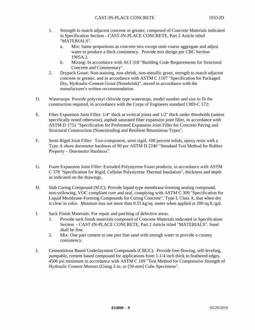
CAST-IN-PLACE CONCRETE 1933.ID
1. Strength to match adjacent concrete or greater, composed of Concrete Materials indicated in Specification Section - CAST-IN-PLACE CONCRETE, Part 2 Article titled "MATERIALS".a. Mix: Same proportions as concrete mix except omit coarse aggregate and adjust
water to produce a thick consistency. Provide mix design per CBC Section 1905A.2.
b. Mixing: In accordance with ACI 318 "Building Code Requirements for Structural Concrete and Commentary".
2. Drypack Grout: Non-staining, non-shrink, non-metallic grout, strength to match adjacent concrete or greater, and in accordance with ASTM C 1107 "Specification for Packaged Dry, Hydraulic-Cement Grout (Nonshrink)", mixed in accordance with the manufacturer's written recommendation.
D. Waterstops: Provide polyvinyl chloride type waterstops, model number and size to fit the construction required, in accordance with the Corps of Engineers standard CRD-C 572:
E. Fiber Expansion Joint Filler: 1/4" thick at vertical joints and 1/2" thick under thresholds (unless specifically noted otherwise), asphalt saturated fiber expansion joint filler, in accordance with ASTM D 1751 "Specification for Preformed Expansion Joint Filler for Concrete Paving and Structural Construction (Nonextruding and Resilient Bituminous Types".
F. Semi-Rigid Joint Filler: Two-component, semi-rigid, 100 percent solids, epoxy resin with a Type A shore durometer hardness of 80 per ASTM D 2240 “Standard Test Method for Rubber Property – Durometer Hardness”.
G. Foam Expansion Joint Filler: Extruded Polystyrene Foam products, in accordance with ASTM C 578 "Specification for Rigid, Cellular Polystyrene Thermal Insulation", thickness and depth as indicated on the drawings.
H. Slab Curing Compound (SCC): Provide liquid-type membrane-forming sealing compound, non-yellowing, VOC compliant cure and seal, complying with ASTM C 309 "Specification for Liquid Membrane-Forming Compounds for Curing Concrete", Type I, Class A, that when dry is clear in color. Moisture loss not more than 0.55 kg/sq. meter when applied at 200 sq.ft./gal.
I. Sack Finish Materials: For repair and patching of defective areas.1. Provide sack finish materials composed of Concrete Materials indicated in Specification
Section - CAST-IN-PLACE CONCRETE, Part 2 Article titled "MATERIALS". Sand shall be fine.
2. Mix: One part cement to one part fine sand with enough water to provide a creamy consistency.
J. Cementitious Based Underlayment Compounds (CBUC): Provide free-flowing, self-leveling, pumpable, cement based compound for applications from 1-1/4 inch thick to feathered edges, 4500 psi minimum in accordance with ASTM C 109 "Test Method for Compressive Strength of Hydraulic Cement Mortars (Using 2-in. or [50-mm] Cube Specimens".
033000 - 9 05/29/2019
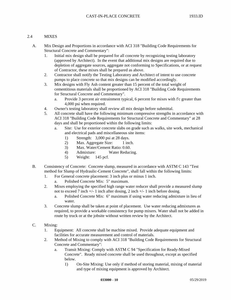
CAST-IN-PLACE CONCRETE 1933.ID
2.4 MIXES
A. Mix Design and Proportions in accordance with ACI 318 "Building Code Requirements for Structural Concrete and Commentary":1. Initial mix design shall be prepared for all concrete by recognizing testing laboratory
(approved by Architect). In the event that additional mix designs are required due to depletion of aggregate sources, aggregate not conforming to Specifications, or at request of Contractor, these mixes shall be prepared as above.
2. Contractor shall notify the Testing Laboratory and Architect of intent to use concrete pumps to place concrete so that mix designs can be modified accordingly.
3. Mix designs with Fly Ash content greater than 15 percent of the total weight of cementitious materials shall be proportioned by ACI 318 "Building Code Requirements for Structural Concrete and Commentary".a. Provide 3 percent air entrainment typical, 6 percent for mixes with f'c greater than
4,000 psi when required.4. Owner's testing laboratory shall review all mix design before submittal.5. All concrete shall have the following minimum compressive strengths in accordance with
ACI 318 "Building Code Requirements for Structural Concrete and Commentary" at 28 days and shall be proportioned within the following limits:a. Site: Use for exterior concrete slabs on grade such as walks, site work, mechanical
and electrical pads and miscellaneous site items:1) Strength: 3,000 psi at 28 days.2) Max. Aggregate Size: 1 inch.3) Max. Water/Cement Ratio: 0.60.4) Admixture: Water Reducing.5) Weight: 145 pcf.
B. Consistency of Concrete: Concrete slump, measured in accordance with ASTM C 143 "Test method for Slump of Hydraulic-Cement Concrete", shall fall within the following limits:1. For General concrete placement: 3 inch plus or minus 1 inch.
a. Polished Concrete Mix: 5" maximum.2. Mixes employing the specified high range water reducer shall provide a measured slump
not to exceed 7 inch +/- 1 inch after dosing, 2 inch +/- 1 inch before dosing.a. Polished Concrete Mix: 6" maximum if using water reducing admixture in lieu of
water.3. Concrete slump shall be taken at point of placement. Use water reducing admixtures as
required, to provide a workable consistency for pump mixers. Water shall not be added in route by truck or at the jobsite without written review by the Architect.
C. Mixing:1. Equipment: All concrete shall be machine mixed. Provide adequate equipment and
facilities for accurate measurement and control of materials.2. Method of Mixing to comply with ACI 318 "Building Code Requirements for Structural
Concrete and Commentary": a. Transit Mixing: Comply with ASTM C 94 "Specification for Ready-Mixed
Concrete". Ready mixed concrete shall be used throughout, except as specified below. 1) On-Site Mixing: Use only if method of storing material, mixing of material
and type of mixing equipment is approved by Architect.
033000 - 10 05/29/2019
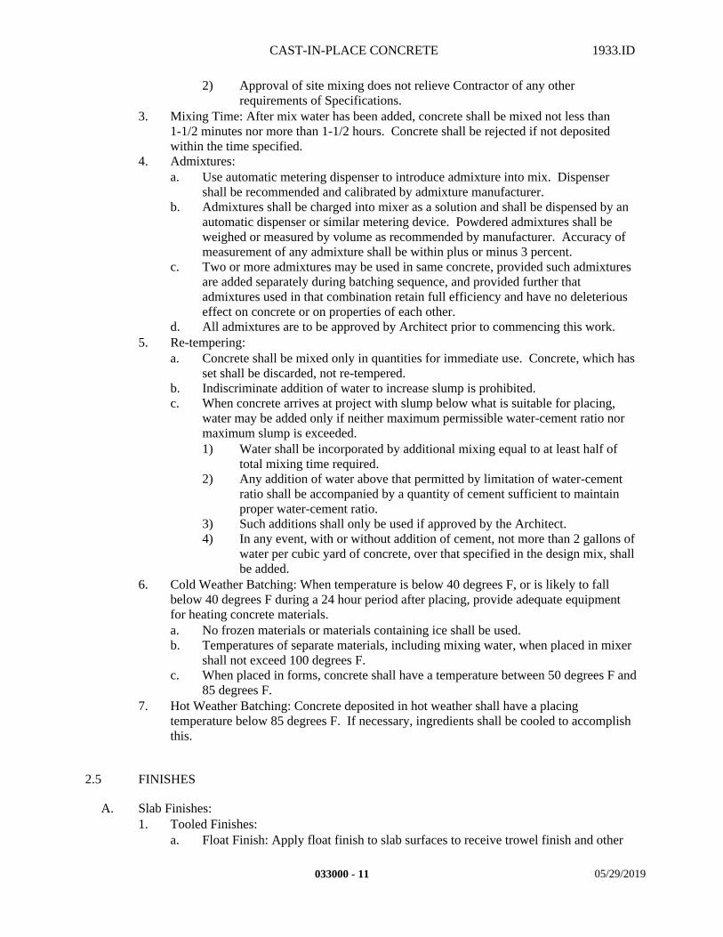
CAST-IN-PLACE CONCRETE 1933.ID
2) Approval of site mixing does not relieve Contractor of any other requirements of Specifications.
3. Mixing Time: After mix water has been added, concrete shall be mixed not less than 1-1/2 minutes nor more than 1-1/2 hours. Concrete shall be rejected if not deposited within the time specified.
4. Admixtures: a. Use automatic metering dispenser to introduce admixture into mix. Dispenser
shall be recommended and calibrated by admixture manufacturer.b. Admixtures shall be charged into mixer as a solution and shall be dispensed by an
automatic dispenser or similar metering device. Powdered admixtures shall be weighed or measured by volume as recommended by manufacturer. Accuracy of measurement of any admixture shall be within plus or minus 3 percent.
c. Two or more admixtures may be used in same concrete, provided such admixtures are added separately during batching sequence, and provided further that admixtures used in that combination retain full efficiency and have no deleterious effect on concrete or on properties of each other.
d. All admixtures are to be approved by Architect prior to commencing this work.5. Re-tempering:
a. Concrete shall be mixed only in quantities for immediate use. Concrete, which has set shall be discarded, not re-tempered.
b. Indiscriminate addition of water to increase slump is prohibited.c. When concrete arrives at project with slump below what is suitable for placing,
water may be added only if neither maximum permissible water-cement ratio nor maximum slump is exceeded.1) Water shall be incorporated by additional mixing equal to at least half of
total mixing time required.2) Any addition of water above that permitted by limitation of water-cement
ratio shall be accompanied by a quantity of cement sufficient to maintain proper water-cement ratio.
3) Such additions shall only be used if approved by the Architect.4) In any event, with or without addition of cement, not more than 2 gallons of
water per cubic yard of concrete, over that specified in the design mix, shall be added.
6. Cold Weather Batching: When temperature is below 40 degrees F, or is likely to fall below 40 degrees F during a 24 hour period after placing, provide adequate equipment for heating concrete materials.a. No frozen materials or materials containing ice shall be used.b. Temperatures of separate materials, including mixing water, when placed in mixer
shall not exceed 100 degrees F.c. When placed in forms, concrete shall have a temperature between 50 degrees F and
85 degrees F.7. Hot Weather Batching: Concrete deposited in hot weather shall have a placing
temperature below 85 degrees F. If necessary, ingredients shall be cooled to accomplish this.
2.5 FINISHES
A. Slab Finishes:1. Tooled Finishes:
a. Float Finish: Apply float finish to slab surfaces to receive trowel finish and other
033000 - 11 05/29/2019
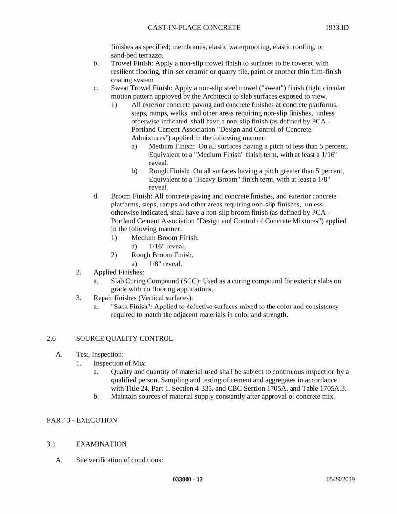
CAST-IN-PLACE CONCRETE 1933.ID
finishes as specified; membranes, elastic waterproofing, elastic roofing, or sand-bed terrazzo.
b. Trowel Finish: Apply a non-slip trowel finish to surfaces to be covered with resilient flooring, thin-set ceramic or quarry tile, paint or another thin film-finish coating system
c. Sweat Trowel Finish: Apply a non-slip steel trowel ("sweat") finish (tight circular motion pattern approved by the Architect) to slab surfaces exposed to view. 1) All exterior concrete paving and concrete finishes at concrete platforms,
steps, ramps, walks, and other areas requiring non-slip finishes, unless otherwise indicated, shall have a non-slip finish (as defined by PCA - Portland Cement Association "Design and Control of Concrete Admixtures") applied in the following manner: a) Medium Finish: On all surfaces having a pitch of less than 5 percent,
Equivalent to a "Medium Finish" finish term, with at least a 1/16" reveal.
b) Rough Finish: On all surfaces having a pitch greater than 5 percent, Equivalent to a "Heavy Broom" finish term, with at least a 1/8" reveal.
d. Broom Finish: All concrete paving and concrete finishes, and exterior concrete platforms, steps, ramps and other areas requiring non-slip finishes, unless otherwise indicated, shall have a non-slip broom finish (as defined by PCA - Portland Cement Association "Design and Control of Concrete Mixtures") applied in the following manner:1) Medium Broom Finish.
a) 1/16" reveal.2) Rough Broom Finish.
a) 1/8" reveal.2. Applied Finishes:
a. Slab Curing Compound (SCC): Used as a curing compound for exterior slabs on grade with no flooring applications.
3. Repair finishes (Vertical surfaces):a. "Sack Finish": Applied to defective surfaces mixed to the color and consistency
required to match the adjacent materials in color and strength.
2.6 SOURCE QUALITY CONTROL
A. Test, Inspection:1. Inspection of Mix:
a. Quality and quantity of material used shall be subject to continuous inspection by a qualified person. Sampling and testing of cement and aggregates in accordance with Title 24, Part 1, Section 4-335, and CBC Section 1705A, and Table 1705A.3.
b. Maintain sources of material supply constantly after approval of concrete mix.
PART 3 - EXECUTION
3.1 EXAMINATION
A. Site verification of conditions:
033000 - 12 05/29/2019
CAST-IN-PLACE CONCRETE 1933.ID
1. Contractor shall inspect bearing soil and report soft or loose unsuitable bearing soil to Architect.
2. Architect will furnish Contractor with corrective measures necessary to remedy field condition.
3. Do not pour concrete until suitable bearing surfaces are achieved.4. Contractor shall inspect and identify any site conditions and/or design information that
prevents the Contractor from complying with the laws, regulations and/or building codes governing ADA access compliance.
3.2 PREPARATION
A. Transportation of Concrete:1. Handle Concrete from mixer to place of final deposit as rapidly as practical by methods
which shall prevent the separation or loss of the ingredients in accordance with ACI 304.3R "Heavyweight Concrete Measuring, Mixing, Transporting, and Placing".
2. Do not move concrete horizontally by means of vibrators.3. Deposit concrete as nearly as practical at its final position in a manner which, will ensure
that required quality is obtained.4. Chutes shall slope not less than 4 inches and not more than 6 inches per foot of horizontal
run.
B. Protection:1. At old concrete or concrete which has begun to set upon which Concrete is to be placed:
a. Surface shall be level, cleaned of all laitance and rough with solidly embedded large aggregate exposed.
b. Rough surface by chipping entire surface not earlier than 5 days after set, by high pressure hosing (80 pounds per square inch) 2 to 4 hours after placing or by sand blasting with coarse silica sand, roughness amplitude shall be at least 1/4 inch.
c. Not more than 1/2 hour prior to pouring concrete, place 2 inch thick uniform layer of grout on old concrete.
C. Surface preparation:1. Prepare all Sand Base,[[ Rock Base,][material as applicable prior to forming footings and
trenches. 2. Remove all water from excavation. Divert flow of water through drains using methods
to avoid washing over freshly deposited concrete.3. Remove hardened concrete, wood chips, shavings and other debris from interior of forms
and from reinforcing steel by vacuum process.a. No wooden ties or blocking shall be left in concrete except where indicated for
attachment of other work.4. Forms shall have been erected, adequately braced, cleaned, sealed, lubricated if required,
and bulkheaded where placing is to stop.5. Any wood forms other than plywood shall be thoroughly water soaked before placing any
concrete. a. The wetting of forms shall be started at least 12 hours before concreting.
6. Reinforcing steel shall have been placed, tied and supported.7. Coordinate with Specification Section - SOIL TREATMENT before placing any
concrete.8. Embedded work of all trades shall be in place in the forms and adequately tied and
braced.
033000 - 13 05/29/2019
CAST-IN-PLACE CONCRETE 1933.ID
9. Reinforcing steel, at the time the concrete is placed around it, shall be cleaned of scale, mill scale or other contaminants that will destroy or reduce bond.
10. Concrete surfaces to which fresh concrete is to be bonded shall be brush cleaned to remove all dust and foreign matter and to expose the aggregate, and then coated with the bonding adhesive herein specified.
11. Prior to placing concrete for any slabs on grade, the moisture content of the subgrade below the slabs shall be adjusted to at least optimum moisture.
12. No concrete shall be placed until formwork, reinforcement, and embedded items have been approved by the Architect.a. Clean forms of all debris and remove standing water.b. Thoroughly clean reinforcement and all handling equipment for mixing and
transporting concrete.c. Concrete shall not be placed against reinforcing steel that is hot to the touch.
13. Provide runways or other approved means for wheeled equipment. Do not wheel equipment over reinforcing or formwork.
3.3 INSTALLATION
A. Placing of Rock BaseorSand Base].1. Rock Base:
a. Shall occur after scarification and compaction operations.b. Preparation of sub-grade and selection and placing of Rock Base subject to
continuous inspection and supervision of Geotechnical Engineer.c. Compact Rock Base to a density of not less than ninety-two (92) percent, but not
more than ninety-five (95) percent, in accordance with Test Designation ASTM D 1557 "Test methods for Laboratory Compaction Characteristics of Soil Using Modified Effort (56,000 ft.-lb./sq.ft.)".1) Density of each layer of Rock Base shall be tested and verified that it meets
required density of Geotechnical Engineer prior to placing any other succeeding layers.
d. Roll Rock Base under interior (and any designated exterior slabs) to smooth surface, free of large or sharp particles.
e. Conduct work to minimize inspection costs.f. Costs of initial compaction tests shall be borne by the Owner.
1) Contractor shall pay for all re-tests required due to failure of initial tests.2. Vapor Retarder:
a. Follow ASTM E1643 "Standard Practice and Procedure for Installation of Vapor Retarder used in Contact with Earth Fill Under Concrete Slabs".
b. General:1) Level, tamp or roll Earth Fill or Base Material beneath the slab in thickness
as indicated on the drawings. Remove all sharp objects that could puncture the Vapor Retarder.
2) Unroll Vapor Retarder over the area where the slab is to be poured, with the longest direction parallel with the direction of the pour.
3) Cut to size, if necessary. Vapor Retarder used shall completely cover the pour area.
4) All joints/seams, both lateral and butt, shall be overlapped six (6) inches and taped using a compatible four (4) inch wide Pressure Sensitive Seaming Tape.
033000 - 14 05/29/2019
CAST-IN-PLACE CONCRETE 1933.ID
a) Tape areas shall be free from dust, dirt and moisture to allow maximum adhesion of the pressure sensitive tape.
5) Vapor Retarder shall overlap six (6) inches and seal to top of all footings and against any vertical walls. Provide manufacturer's written recommended sealant.
6) Repair any damaged areas in accordance with manufacturer's written recommendations, and overlap all repairs a minimum of six (6) inches in all directions with Vapor Retarder Material, Pressure Sensitive Tape, and Vapor Proofing Mastic.
7) Follow manufacturer's written recommendations for all Vertical Wall Applications.
c. Penetrations:1) Seal all penetrations and check that all pipe, ductwork, rebar, wire
penetrations and block-outs are thoroughly sealed.2) Single Pipe Penetrations may be sealed using pipe boot constructed from the
product.a) Cut a piece of plastic, width - 12 inches, length - 1 and 1/2 times the
circumference of the pipe with scissors; cut slits half the width of the film, and wrap the boot around the pipe; tape onto pipe and completely tape the base to the Vapor Retarder.
3) Multiple pipe penetrations in close proximity and very small pipes may be sealed using Vapor Proofing Mastic.a) Cut out small area around pipes; cut a patch of Vapor Retarder
extending at least 6 inches past the cut out in all directions; cut X's or small circles in the patch and install over pipes; overlap at least 6 inches and tape; build up 40-60 mils of mastic, or as needed to completely fill all voids between the pipe and Vapor Retarder.
4) No penetration of the Vapor Retarder is allowed except for reinforcing steel and permanent utilities.a) In the case that forms must be used vapor stakes should be used to
hold forms in place.b) Penetrate plastic with stake; treat stake as pipe penetration (see above
"penetration" paragraphs; leave stake permanently in concrete; using a power saw, cut stake off above the seal, but below the concrete finished surface; the lower portion of the vapor stake remains in place, permanently plugging the penetration.
3. Sand base:a. Shall occur after scarification and compaction operations.b. Preparation of any sub-grade Engineered Fill, Rock Base sub-bases, placing of
Vapor Retarder, and placing of Sand Base subject to continuous inspection and supervision of Geotechnical Engineer.
c. Compact Sand Base to a density of not less than ninety-two (92) percent, but not more than ninety-five (95) percent, in accordance with Test Designation ASTM D 1557 "Test method for Laboratory Compaction Characteristics of Soil Using Modified Effort (56,000 ft-lb/sq.ft.)".1) Density of each layer of Sand Base shall be tested and verified that it meets
required density of Geotechnical Engineer prior to placing any succeeding layers.
d. Roll Sand Base under interior (and any designated exterior slabs) to smooth surface, free of large or sharp particles.
033000 - 15 05/29/2019
CAST-IN-PLACE CONCRETE 1933.ID
e. Conduct work to minimize inspection costs.f. Costs of initial compaction tests shall be borne by the Owner. Contractor shall pay
for all re-tests required due to failure of initial tests.
B. Joints:1. General: Construct joints straight, horizontal, true with faces perpendicular to surface
plane of concrete and free of "overhangs" or "lips" to line. 2. Construction Joints:
a. Location: as indicated or as approved by Architect.1) Install as to least impair strength of structure, appearance of concrete and
shall conform to typical details and in accordance with ACI Standards.a) Joints between concrete and masonry shall be considered construction
joints.b. Spacing: Pour lengths shall be as follows, unless specifically noted otherwise.
1) Exterior Slabs on grade 30 feet o.c. maximumc. Installation:
1) Construction joints shall have level tops, vertical sides.2) Construction joints shall be thoroughly cleaned and roughened by removing
entire surface film and exposing clean aggregate solidly embedded in mortar matrix.
3) See drawings for doweling and required keys.4) Roughen construction joints by any of the following methods:
a) By sandblasting joint.b) By thoroughly washing joint, using a high pressure hose, after
concrete has taken initial set. Washing shall be done not less than 2 hours nor more than 4 hours after concrete has been poured, depending upon setting time.
c) By chipping and wire brushing.d) Vertical construction joints need not be roughened
5) All decisions pertaining to adequacy of construction joint surfaces and to compliance with requirements pertaining to construction joints shall be reviewed with the Architect.
6) Just before starting new pour, horizontal and vertical joint surfaces shall be dampened (but not saturated).
7) Before placing regular concrete mix, horizontal and vertical joint surfaces shall be covered with a layer of mortar composed of cement and fine aggregate of same proportions as that used in prescribed mix, but omitting coarse aggregate.
3. Expansion Joints:a. Location: as indicated or as approved by Architect.
1) Exterior slabs on grade: locate at walks, curbs, gutters, etc.a) Locate at each side of structure/vertical surface, curb transition
opposite apron joints, end of curb returns, and back of curb when adjacent to walk.
b. Spacing:1) Exterior Slabs on grade: 30 feet o.c. maximum, unless otherwise noted.
c. Installation:1) Install Expansion Filler in expansion joints.
a) Extend joint-filler strips full width and depth of joint, terminating flush with finished concrete surface unless noted otherwise.
033000 - 16 05/29/2019
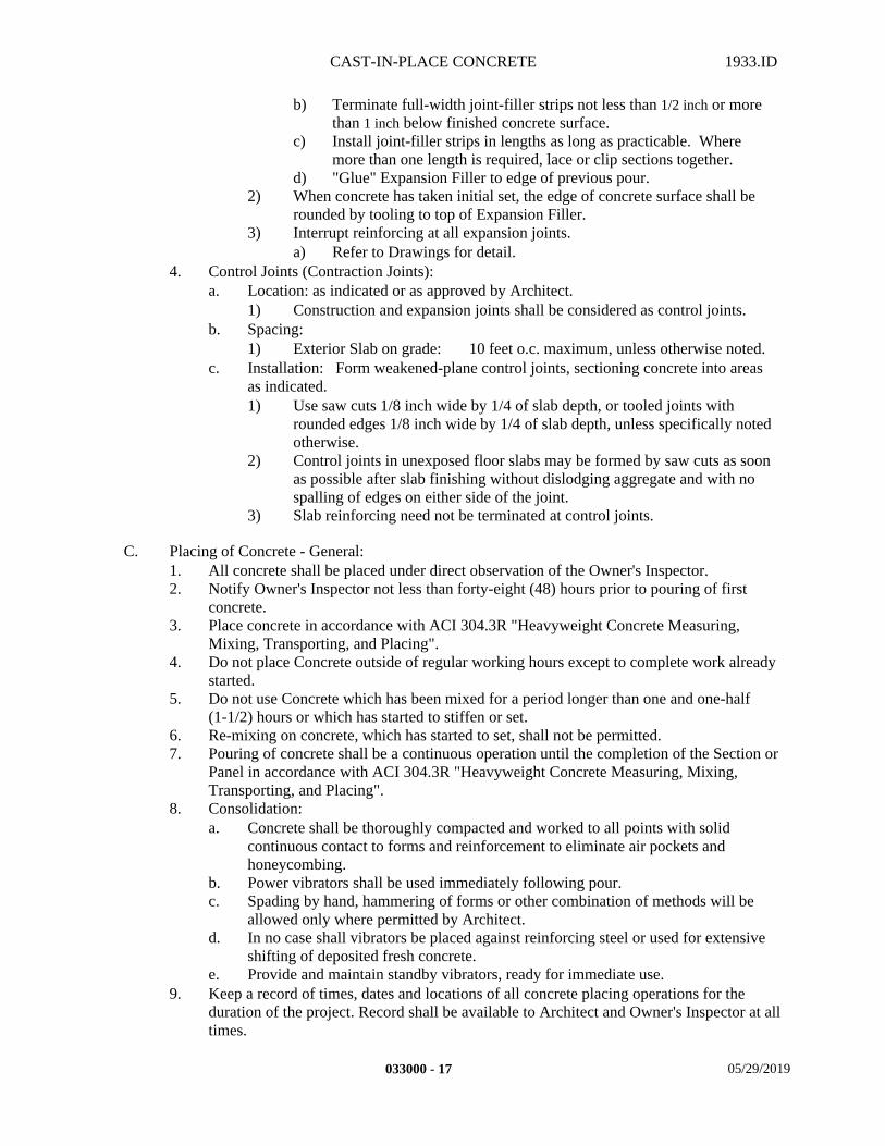
CAST-IN-PLACE CONCRETE 1933.ID
b) Terminate full-width joint-filler strips not less than 1/2 inch or more than 1 inch below finished concrete surface.
c) Install joint-filler strips in lengths as long as practicable. Where more than one length is required, lace or clip sections together.
d) "Glue" Expansion Filler to edge of previous pour.2) When concrete has taken initial set, the edge of concrete surface shall be
rounded by tooling to top of Expansion Filler.3) Interrupt reinforcing at all expansion joints.
a) Refer to Drawings for detail.4. Control Joints (Contraction Joints):
a. Location: as indicated or as approved by Architect.1) Construction and expansion joints shall be considered as control joints.
b. Spacing:1) Exterior Slab on grade: 10 feet o.c. maximum, unless otherwise noted.
c. Installation: Form weakened-plane control joints, sectioning concrete into areas as indicated.1) Use saw cuts 1/8 inch wide by 1/4 of slab depth, or tooled joints with
rounded edges 1/8 inch wide by 1/4 of slab depth, unless specifically noted otherwise.
2) Control joints in unexposed floor slabs may be formed by saw cuts as soon as possible after slab finishing without dislodging aggregate and with no spalling of edges on either side of the joint.
3) Slab reinforcing need not be terminated at control joints.
C. Placing of Concrete - General:1. All concrete shall be placed under direct observation of the Owner's Inspector.2. Notify Owner's Inspector not less than forty-eight (48) hours prior to pouring of first
concrete.3. Place concrete in accordance with ACI 304.3R "Heavyweight Concrete Measuring,
Mixing, Transporting, and Placing".4. Do not place Concrete outside of regular working hours except to complete work already
started.5. Do not use Concrete which has been mixed for a period longer than one and one-half
(1-1/2) hours or which has started to stiffen or set.6. Re-mixing on concrete, which has started to set, shall not be permitted.7. Pouring of concrete shall be a continuous operation until the completion of the Section or
Panel in accordance with ACI 304.3R "Heavyweight Concrete Measuring, Mixing, Transporting, and Placing".
8. Consolidation:a. Concrete shall be thoroughly compacted and worked to all points with solid
continuous contact to forms and reinforcement to eliminate air pockets and honeycombing.
b. Power vibrators shall be used immediately following pour.c. Spading by hand, hammering of forms or other combination of methods will be
allowed only where permitted by Architect.d. In no case shall vibrators be placed against reinforcing steel or used for extensive
shifting of deposited fresh concrete.e. Provide and maintain standby vibrators, ready for immediate use.
9. Keep a record of times, dates and locations of all concrete placing operations for the duration of the project. Record shall be available to Architect and Owner's Inspector at all times.
033000 - 17 05/29/2019
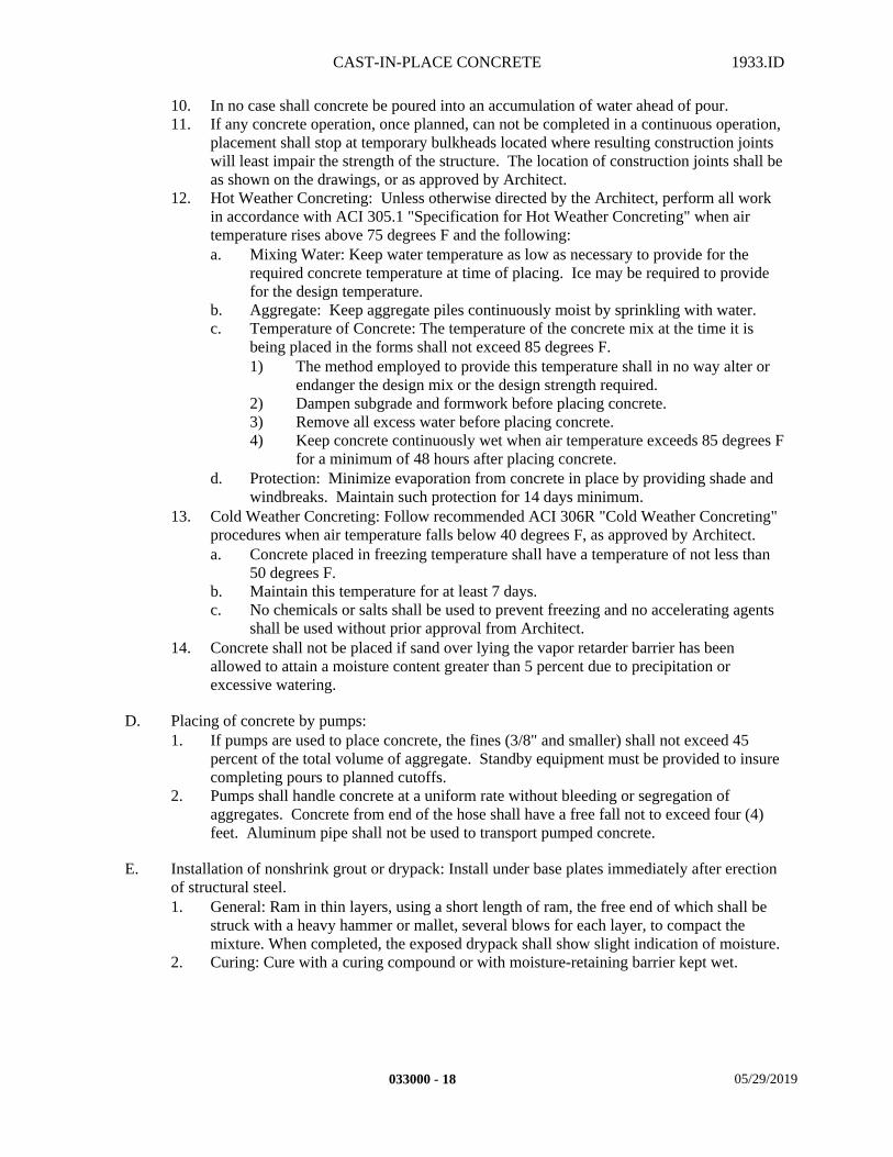
CAST-IN-PLACE CONCRETE 1933.ID
10. In no case shall concrete be poured into an accumulation of water ahead of pour.11. If any concrete operation, once planned, can not be completed in a continuous operation,
placement shall stop at temporary bulkheads located where resulting construction joints will least impair the strength of the structure. The location of construction joints shall be as shown on the drawings, or as approved by Architect.
12. Hot Weather Concreting: Unless otherwise directed by the Architect, perform all work in accordance with ACI 305.1 "Specification for Hot Weather Concreting" when air temperature rises above 75 degrees F and the following:a. Mixing Water: Keep water temperature as low as necessary to provide for the
required concrete temperature at time of placing. Ice may be required to provide for the design temperature.
b. Aggregate: Keep aggregate piles continuously moist by sprinkling with water. c. Temperature of Concrete: The temperature of the concrete mix at the time it is
being placed in the forms shall not exceed 85 degrees F.1) The method employed to provide this temperature shall in no way alter or
endanger the design mix or the design strength required.2) Dampen subgrade and formwork before placing concrete.3) Remove all excess water before placing concrete.4) Keep concrete continuously wet when air temperature exceeds 85 degrees F
for a minimum of 48 hours after placing concrete.d. Protection: Minimize evaporation from concrete in place by providing shade and
windbreaks. Maintain such protection for 14 days minimum.13. Cold Weather Concreting: Follow recommended ACI 306R "Cold Weather Concreting"
procedures when air temperature falls below 40 degrees F, as approved by Architect.a. Concrete placed in freezing temperature shall have a temperature of not less than
50 degrees F.b. Maintain this temperature for at least 7 days.c. No chemicals or salts shall be used to prevent freezing and no accelerating agents
shall be used without prior approval from Architect.14. Concrete shall not be placed if sand over lying the vapor retarder barrier has been
allowed to attain a moisture content greater than 5 percent due to precipitation or excessive watering.
D. Placing of concrete by pumps:1. If pumps are used to place concrete, the fines (3/8" and smaller) shall not exceed 45
percent of the total volume of aggregate. Standby equipment must be provided to insure completing pours to planned cutoffs.
2. Pumps shall handle concrete at a uniform rate without bleeding or segregation of aggregates. Concrete from end of the hose shall have a free fall not to exceed four (4) feet. Aluminum pipe shall not be used to transport pumped concrete.
E. Installation of nonshrink grout or drypack: Install under base plates immediately after erection of structural steel.1. General: Ram in thin layers, using a short length of ram, the free end of which shall be
struck with a heavy hammer or mallet, several blows for each layer, to compact the mixture. When completed, the exposed drypack shall show slight indication of moisture.
2. Curing: Cure with a curing compound or with moisture-retaining barrier kept wet.
033000 - 18 05/29/2019
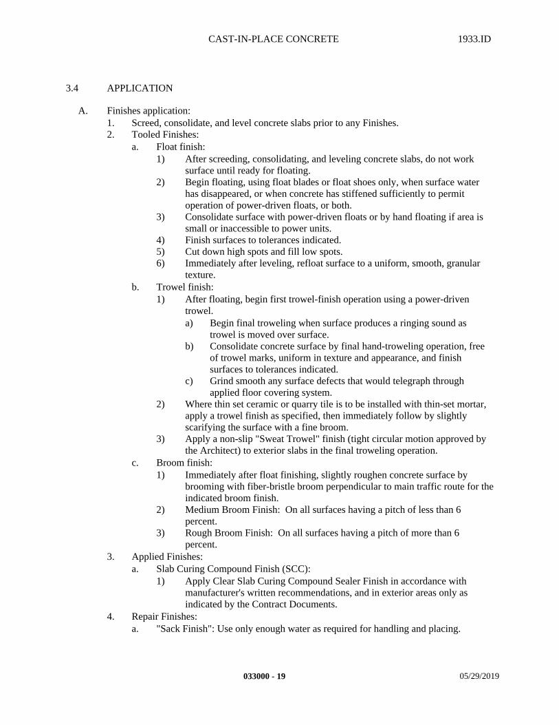
CAST-IN-PLACE CONCRETE 1933.ID
3.4 APPLICATION
A. Finishes application:1. Screed, consolidate, and level concrete slabs prior to any Finishes. 2. Tooled Finishes:
a. Float finish:1) After screeding, consolidating, and leveling concrete slabs, do not work
surface until ready for floating.2) Begin floating, using float blades or float shoes only, when surface water
has disappeared, or when concrete has stiffened sufficiently to permit operation of power-driven floats, or both.
3) Consolidate surface with power-driven floats or by hand floating if area is small or inaccessible to power units.
4) Finish surfaces to tolerances indicated.5) Cut down high spots and fill low spots.6) Immediately after leveling, refloat surface to a uniform, smooth, granular
texture.b. Trowel finish:
1) After floating, begin first trowel-finish operation using a power-driven trowel.a) Begin final troweling when surface produces a ringing sound as
trowel is moved over surface.b) Consolidate concrete surface by final hand-troweling operation, free
of trowel marks, uniform in texture and appearance, and finish surfaces to tolerances indicated.
c) Grind smooth any surface defects that would telegraph through applied floor covering system.
2) Where thin set ceramic or quarry tile is to be installed with thin-set mortar, apply a trowel finish as specified, then immediately follow by slightly scarifying the surface with a fine broom.
3) Apply a non-slip "Sweat Trowel" finish (tight circular motion approved by the Architect) to exterior slabs in the final troweling operation.
c. Broom finish:1) Immediately after float finishing, slightly roughen concrete surface by
brooming with fiber-bristle broom perpendicular to main traffic route for the indicated broom finish.
2) Medium Broom Finish: On all surfaces having a pitch of less than 6 percent.
3) Rough Broom Finish: On all surfaces having a pitch of more than 6 percent.
3. Applied Finishes: a. Slab Curing Compound Finish (SCC):
1) Apply Clear Slab Curing Compound Sealer Finish in accordance with manufacturer's written recommendations, and in exterior areas only as indicated by the Contract Documents.
4. Repair Finishes:a. "Sack Finish": Use only enough water as required for handling and placing.
033000 - 19 05/29/2019
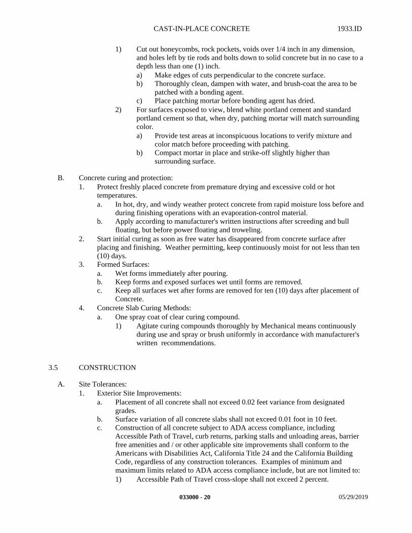
CAST-IN-PLACE CONCRETE 1933.ID
1) Cut out honeycombs, rock pockets, voids over 1/4 inch in any dimension, and holes left by tie rods and bolts down to solid concrete but in no case to a depth less than one (1) inch.a) Make edges of cuts perpendicular to the concrete surface.b) Thoroughly clean, dampen with water, and brush-coat the area to be
patched with a bonding agent.c) Place patching mortar before bonding agent has dried.
2) For surfaces exposed to view, blend white portland cement and standard portland cement so that, when dry, patching mortar will match surrounding color.a) Provide test areas at inconspicuous locations to verify mixture and
color match before proceeding with patching.b) Compact mortar in place and strike-off slightly higher than
surrounding surface.
B. Concrete curing and protection:1. Protect freshly placed concrete from premature drying and excessive cold or hot
temperatures.a. In hot, dry, and windy weather protect concrete from rapid moisture loss before and
during finishing operations with an evaporation-control material.b. Apply according to manufacturer's written instructions after screeding and bull
floating, but before power floating and troweling.2. Start initial curing as soon as free water has disappeared from concrete surface after
placing and finishing. Weather permitting, keep continuously moist for not less than ten (10) days.
3. Formed Surfaces:a. Wet forms immediately after pouring.b. Keep forms and exposed surfaces wet until forms are removed.c. Keep all surfaces wet after forms are removed for ten (10) days after placement of
Concrete.4. Concrete Slab Curing Methods:
a. One spray coat of clear curing compound.1) Agitate curing compounds thoroughly by Mechanical means continuously
during use and spray or brush uniformly in accordance with manufacturer's written recommendations.
3.5 CONSTRUCTION
A. Site Tolerances:1. Exterior Site Improvements:
a. Placement of all concrete shall not exceed 0.02 feet variance from designated grades.
b. Surface variation of all concrete slabs shall not exceed 0.01 foot in 10 feet.c. Construction of all concrete subject to ADA access compliance, including
Accessible Path of Travel, curb returns, parking stalls and unloading areas, barrier free amenities and / or other applicable site improvements shall conform to the Americans with Disabilities Act, California Title 24 and the California Building Code, regardless of any construction tolerances. Examples of minimum and maximum limits related to ADA access compliance include, but are not limited to:1) Accessible Path of Travel cross-slope shall not exceed 2 percent.
033000 - 20 05/29/2019
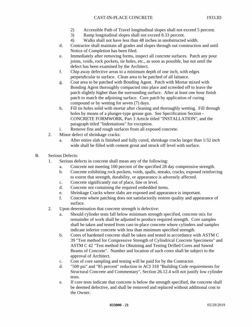
CAST-IN-PLACE CONCRETE 1933.ID
2) Accessible Path of Travel longitudinal slopes shall not exceed 5 percent.3) Ramp longitudinal slopes shall not exceed 8.33 percent.4) Walks shall not have less than 48 inches in unobstructed width.
d. Contractor shall maintain all grades and slopes through out construction and until Notice of Completion has been filed.
e. Immediately after removing forms, inspect all concrete surfaces. Patch any pour joints, voids, rock pockets, tie holes, etc., as soon as possible, but not until the defect has been examined by the Architect.
f. Chip away defective areas to a minimum depth of one inch, with edges perpendicular to surface. Clean area to be patched of all laitance.
g. Coat area to be patched with Bonding Agent. Patch with Mortar mixed with Bonding Agent thoroughly compacted into place and screeded off to leave the patch slightly higher than the surrounding surface. After at least one hour finish patch to match the adjoining surface. Cure patch by application of curing compound or by wetting for seven (7) days.
h. Fill tie holes solid with mortar after cleaning and thoroughly wetting. Fill through holes by means of a plunger-type grease gun. See Specification Section - CONCRETE FORMWORK, Part 3 Article titled "INSTALLATION", and the paragraph titled "Indentations" for exception.
i. Remove fins and rough surfaces from all exposed concrete.2. Minor defect of shrinkage cracks:
a. After entire slab is finished and fully cured, shrinkage cracks larger than 1/32 inch wide shall be filled with cement grout and struck off level with surface.
B. Serious Defects:1. Serious defects in concrete shall mean any of the following:
a. Concrete not meeting 100 percent of the specified 28 day compressive strength.b. Concrete exhibiting rock pockets, voids, spalls, streaks, cracks, exposed reinforcing
to extent that strength, durability, or appearance is adversely affected.c. Concrete significantly out of place, line or level.d. Concrete not containing the required embedded items.e. Shrinkage Cracks where slabs are exposed and appearance is important.f. Concrete where patching does not satisfactorily restore quality and appearance of
surface.2. Upon determination that concrete strength is defective:
a. Should cylinder tests fall below minimum strength specified, concrete mix for remainder of work shall be adjusted to produce required strength. Core samples shall be taken and tested from cast-in-place concrete where cylinders and samples indicate inferior concrete with less than minimum specified strength.
b. Cores of hardened concrete shall be taken and tested in accordance with ASTM C 39 "Test method for Compressive Strength of Cylindrical Concrete Specimens" and ASTM C 42 "Test method for Obtaining and Testing Drilled Cores and Sawed Beams of Concrete". Number and location of such cores shall be subject to the approval of Architect.
c. Cost of core sampling and testing will be paid for by the Contractor.d. "500 psi" and "85 percent" reduction in ACI 318 "Building Code requirements for
Structural Concrete and Commentary", Section 26.12.4 will not justify low cylinder tests.
e. If core tests indicate that concrete is below the strength specified, the concrete shall be deemed defective, and shall be removed and replaced without additional cost to the Owner.
033000 - 21 05/29/2019
CAST-IN-PLACE CONCRETE 1933.ID
3. Major defect of shrinkage cracks.a. After entire slab is finished and fully cured, unsightly shrinkage cracks shall be
repaired in a manner satisfactory in appearance to the Architect. If this cannot be accomplished, concrete shall be considered defective.
4. Upon determining that concrete surface is defective:a. Contractor may restore concrete to acceptable condition by cutting, chipping,
pointing, patching, grinding, if this can be done without significantly altering strength of structure.
b. Permission to patch defective areas will not be considered a waiver of the right to require removal if patching does not, in the opinion of the Architect, satisfactorily restore quality and appearance.
c. If patching does not restore concrete to specified quality and appearance, the concrete shall be deemed defective, and shall be removed and replaced without additional cost to the Owner.
d. No repair work shall begin until concrete has been examined and procedures have been reviewed by the Architect and Structural Engineer and approved by AHJ .
5. Repair defects by complete removal of concrete and replacement or repair defects with Shotcrete in accordance with CBC Sections 1913A, strength to match mix design and material being repaired.
6. Place and cure Shotcrete in accordance with CBC Section 1913A.7. Inspect and test Shotcrete as per CBC Section 1705A.4, Table 1705A.4.
C. Cost of repairing shall be borne by the Contractor.
3.6 FIELD QUALITY CONTROL
A. Contractor's Field Quality Control:1. Contractor shall protect slabs receiving flooring products from excess moisture after the
curing process, removing excess moisture after rains, broken water pipes, etc., to ensure that the monolithic slabs are dry enough for application of flooring products. When all spaces have been enclosed, acclimate the building as soon as possible with the building's own mechanical heating and cooling system, and other outside devices as required to properly prepare the monolithic slabs for flooring installation. a. The test sites for the RH Tests shall be at the same room temperature and humidity
expected during normal use. If this is not possible, then the test site conditions should be 75 degrees F (plus or minus 10 degrees F) and 50 percent relative humidity (plus or minus 10 percent relative humidity) 48 hours prior to, and during testing.
2. Contractor shall maintain temperature and humidity in a manner not deleterious to the flooring materials installed until the Owner assumes occupancy.
B. Inspection:1. Project Inspector shall inspect placement of concrete and grout.
3.7 CLEANING
A. Remove all debris, excess materials, tools, and equipment resulting from or used in this operation at completion of work.
033000 - 22 05/29/2019
CAST-IN-PLACE CONCRETE 1933.ID
END OF SECTION
033000 - 23 05/29/2019

STEEL AND FABRICATIONS 1933.ID
SECTION 051200 – STEEL AND FABRICATIONS
PART 1 - GENERAL
1.1 SUMMARY
A. This Section includes the following:1. Provide all material, labor, equipment and services necessary to completely install all
Steel and Fabrications, accessories and other related items necessary to complete the Project as indicated by the Contract Documents.
B. Related Sections: The following Project Manual Sections contain requirements that relate to this section:1. ALL DIVISION 00 SPECIFICATION SECTIONS.2. ALL DIVISION 01 SPECIFICATION SECTIONS. 3. 03 11 01 CONCRETE FORMWORK4. 03 15 14 DRILLED ANCHORS5. 03 20 00 REINFORCEMENT6. 03 30 00 CAST-IN-PLACE CONCRETE (Grouting of Bearing Plate)7. 07 60 00 SHEET METAL8. 09 22 16 METAL FRAMING9. 09 91 00 PAINTING10. 10 05 00 MISCELLANEOUS SPECIALTIES11. ALL SPECIFICATION SECTIONS IN THE FACILITY SERVICES SUBGROUP.12. ALL SPECIFICATION SECTIONS IN THE SITE AND INFRASTRUCTURE
SUBGROUP.
1.2 REFERENCES
A. Standards:1. In accordance with Specification Section – REGULATORY REQUIREMENTS and the
following standards:a. AISC: American Institute of Steel Construction "Specification for Design,
Fabrication and Erection of Structural Steel buildings" and "Code of Standard Practice for Steel Buildings and Bridges" and "Recommended Procedure for Identification of High Strength Steels During Fabrication". 1) NOTE: All connections shall be designed by the Structural Engineer and
approved by AHJ.2) NOTE: Paragraph 4.2.1 of the AISC "Code of Standard Practice for Steel
Buildings and Bridges" for fabricator designed connection shown on shop drawings is deleted. All connections shall be as shown in the Contract Document drawings.
3) AISC: "Specification for Architecturally Exposed Structural Steel".4) AISC: "Specification for Structural Joists using A325 or A490 Bolts".5) AISC: “Specification for Structural Steel Buildings” using the AISC
360-05.b. ANSI: American National Standards Institute:
051200 - 1 05/29/2019
STEEL AND FABRICATIONS 1933.ID
1) ANSI B18.22.1 "Plain Washers".2) ANSI B18.22.1 "Beveled Washers".
c. ASTM: American Society for Testing and Materials.1) ASTM A123: Standard Specification for Zinc (Hot-Dipped
Galvanized) Coatings on Iron and Steel Products.2) ASTM A153: Standard Specification for Zinc (Hot-Dip) on Iron and
Steel Hardware.3) ASTM A 385: Standard Practice for Providing High-Quality Zinc
Coatings (Hot-Dip).4) ASTM A780: Standard Specification for Repair of Damaged and
Uncoated Areas of Hot-Dip Galvanized Coatings.d. AWS: American Welding Society "Structural Welding Code".
1) AWS D1.1"Structural Welding Code".2) AWS A2.0"Welding Symbols".
e. EF: Engineering Foundation, "Specification for Structural Joints Using bolts from ASTM A 325 "Standard Specification for Structural Bolts, Steel, Heat Treated, 120/105 ksi Minimum Tensile Strength" or ASTM A 490 "Standard Specification for Heat-Treated Steel Structural Bolts, 150 ksi Minimum Tensile Strength".
f. ICC: International Code Councilg. NAAMM: National Association of Architectural Metal Manufacturers
1) Metal Stairs Manual2) Pipe Rail Manual.
h. RCSC: Research Council on Structural Connections, “Specification for Structural Joints Using ASTM A 325 "Standard Specification for Structural Bolts, Steel, Heat Treated, 120/105 ksi Minimum Tensile Strength" or ASTM A 490 "Standard Specification for Heat-Treated Steel Structural Bolts, 150 ksi Minimum Tensile Strength".
i. SSPC: The Society for Protective Coatings.1) SSPC-SP 1 "Solvent Cleaning".2) SSPC-SP 2 "Hand Tool Cleaning".3) SSPC-SP 3 "Power Tool Cleaning".4) SSPC-SP 6 "Commercial Blast Cleaning".5) SSPC-SP 7 "Brush-Off Blast Cleaning".
1.3 DEFINITIONS
A. Welding Definitions:1. CVN Charpy V-Notch (Testing Procedure).2. FCAW Flux Core Arc Welding.3. FCAW-G Flux Core Arc Welding-Gas Shielded.4. FCAW-SS Flux Core Arc Welding-Self Shielded.5. G-MAW Gas Metal Arc Welding.6. SMAW Shielded Metal Arc Welding.7. SAW Submerged Arc Welding.
1.4 SUBMITTALS
A. Submit in accordance with Specification Section - SUBMITTAL PROCEDURES:1. Product Data.
051200 - 2 05/29/2019
STEEL AND FABRICATIONS 1933.ID
a. Submit Load Indicating Device information as indicated in Part 3 of this Specification Section, and include Laboratory Test Reports and other data to show compliance with Specification (include Specified Standards).
b. Include certified copies of mill reports covering chemical and physical properties of each type of steel.
c. Submit primer paint system. Obtain certification from the project's Painting Contractor and Paint Manufacturer that primer paint system is compatible with proposed painting systems for this project.
2. Shop Drawings.a. The Contract Drawings represent the spatial relationship as conceived by the
Architect.1) The production of the structural steel Shop Drawings may require the
employment and utilization of a 3-dimensional structural steel fabrication layout program to achieve the exact relationship of all intersecting members.
2) Building sections and details represent interpretations of these relationships and the dimensions shown shall not be relied upon for accuracy and fit, but the Contractor / Structural Steel Fabricator shall verify them and double-check them for accuracy and fit.
3) Any significant variations shall be submitted to the Architect and Structural Engineer for review and approval, of which the conditions may or may not require AHJ review and approval.
4) "Fit-Up" means and methods are the sole responsibility of the Contractor.b. Provide all information necessary for the fabrication of component parts. Indicate
size and weight of members, type and location of shop and field connections, size and extent of all welds, and welding sequence when required.
c. Include details of cuts, connections, camber, holes and other pertinent data. Include welds by Standard AWS Symbols, and show size, length and type of each weld.
d. Provide sections, drawings, templates and directions for installation of anchor bolts and other anchors.
e. Dimension requirements of structural steel for manufactured items, such as Mechanical Equipment, Dock Levelers, etc. All of these items shall be coordinated and provided by the General Contractor. The General Contractor shall also coordinate and provide dimensions to locate Structural Steel for Window Washing supports such as davits, tie-backs, etc.
3. Samples.a. Provide material samples cut and machined for testing without charge to the
Owner.4. Quality Assurance/Control Submittals.
a. Test Reports:1) Submit mill analysis and test reports for each heat, in accordance with
ASTM A 6 "General Requirements for Delivery of Rolled Steel Plates, Shapes, Sheet Piling and Bars for Structural Use", certifying conformity with the Specifications. Steel shall be identifiable in the fabricating shop.
2) Submit test reports for each lot of high strength bolts in accordance with ASTM A 325 "Standard Specification for Structural Bolts, Steel, Heat Treated, 120/105 ksi Minimum Tensile Strength" and ASTM A 490 "Standard Specification for Heat-Treated Steel Structural Bolts, 150 ksi Minimum Tensile Strength" .
051200 - 3 05/29/2019
STEEL AND FABRICATIONS 1933.ID
3) Submit Welding Procedure Specification (WPS) to the Structural Engineer for review prior to use.a) For WPS's that have been qualified by test, the supporting Procedure
Qualification Record (PQR) shall be submitted to the Structural Engineer for review prior to use.
4) Submit to the Structural Engineer for approval, a step by step welding sequence for the field welding of each type of connection.
5) Submit to the Structural Engineer a quality control plan that addresses all inspection issues, including in process and final inspection that are addressed in AWS D1.1.
b. Certificates:1) Submit current valid certificate issued by an independent testing agency for
all welders, welding operators, and tack welders.2) Certification of Welder's Qualifications: Welders that will make welds in
restricted access, such as, but not limited to, the bottom flange-to-column welds through a cope hole or access hole in the beam web, shall be qualified by the Contractor using the same welding procedure as will be used for production and a mock-up assembly that simulates the construction configuration.
3) Provide Certified Mill Test Report Sheets in accordance with ASTM A123 “Specification for Zinc (Hot-Dip Galvanized) Coatings on Iron and Steel Products”, certified at the plant after galvanizing, but prior to shipment.
5. Closeout Submittals:a. Project Record Documents in accordance with Specification Section - PROJECT
DOCUMENTS.b. Warranty.
1.5 QUALITY ASSURANCE
A. Qualifications:1. Installer Qualifications:
a. Engage an experienced Installer who has successfully completed three (3) projects of similar scope and size to that indicated for this Project.
b. Welders shall be recently qualified by Test as prescribed in AWS "Structural Welding Code" for the type of welding to be performed.1) All welders, welding operators, and tack welders shall be qualified with the
largest diameter electrode(s) to be used on the work by test and hold a current valid certificate issued by an independent testing agency, to perform the type of welds required by the work; including the process, position, and thickness of materials used (AWS D1.1: 4.19.1).
2) In addition to meeting the requirements of AWS, welders that will make welds with restricted access, such as, but not limited to, the flange to column welds through a cope hole or access hole in the beam web, or where access to the bottom of a groove is restricted by the presence of a column flange, shall be qualified by the Contractor using the same welding procedure as will be used for production and a mock-up assembly that simulates the construction configuration.
3) All welders on the project shall be capable of understanding and following the requirements of the written WPS.
051200 - 4 05/29/2019
STEEL AND FABRICATIONS 1933.ID
4) Each welder employed on the project shall understand all the requirements of this welding specification before welding on the project.
5) The written WPS shall be available to the welder, welding supervisor, and all inspectors.
6) Provide weld procedures for both pre-qualified welds and special welds to be submitted to the Owner's Testing laboratory and the Architect. Procedures shall be provided for both shop & field welds and shall be provided prior to commencing welding operations.
2. Manufacturer/Supplier Qualifications:a. Structural Steel firm experienced in successfully producing/supply capacity to
produce/supply required units without causing delay in the Work.b. Provide documentation that the Hot-Dipped Galvanizer is a member in good
association with the AGA (American Galvanizers Association).
B. Regulatory Requirements:1. In accordance with Specification Section - REGULATORY REQUIREMENTS, and the
following:a. CARB Materials and equipment used for this Project shall comply with the
current applicable regulations of the California Air Resources Board (CARB)and the Environmental Protection Agency (EPA), in the area where the project is located.
1.6 DELIVERY, STORAGE, AND HANDLING
A. Product Handling:1. Store materials to permit easy access for inspection and identification. Keep steel
members off the ground using pallets, platforms, or other supports. Protect steel members and packaged materials from erosion and deterioration.
1.7 SCHEDULING
A. Schedule the Work so that there will be no excessive inspection time. At all times that an inspector is required, sufficient work shall be laid out and adequate personnel supplied so that the Inspector's time will be used to full advantage. If inspection costs become excessive because of poor shop procedure, such excess costs will be paid for by the Owner, but deducted from the Contract Price. Poor procedures will be determined upon review of Inspection and/or Testing Reports. The rate for charging the excess costs will be as follows:1. Minimum of three (3) certified welders are used, Owner will pay 100 percent.2. Only two (2) certified welders are used, Contractor will be charged 1/3 of the Inspection
cost.3. Only one (1) certified welder is used, the Contractor will be charged 2/3 of the inspection
cost.
1.8 WARRANTY
A. Contractor's General Warranty:1. In accordance with Specification Section - WARRANTIES.
051200 - 5 05/29/2019
STEEL AND FABRICATIONS 1933.ID
B. Manufacturer's Warranty:1. In accordance with manufacturer's written standard warranty:
a. Warranty Period One (1) Year.
C. Installer's Warranty:1. In accordance with the terms of the Specification Section - WARRANTIES
a. Warranty Period One (1) Year.
PART 2 - PRODUCTS
2.1 MANUFACTURERS
A. These products listed herein establish the size, pattern, color range and function selected by the Architect for this Project. Manufacturers that are listed as acceptable alternative manufacturers and substitutions must still comply with the requirements of this project and the products listed in order to be approved as an equivalent during the Submittal Process. If the acceptable alternative manufacturers listed or substitutions are not approved during the Submittal Process due to non-compliance with the contract documents, then the Contractor shall submit product specified. 1. Specified galvanized repair paint product manufacturer, or approved equivalent:
a. AERVOE INDUSTIRES, INC.1) Zinc Rich Galvanize "#1141".
B. Products from other manufacturers not listed must submit in accordance with Specification Section - SUBSTITUTION PROCEDURES.
2.2 MATERIALS
A. Steel:1. Structural Shapes, Plates, and Bars: Shall be made in accordance with "Specifications for
Structural Steel", ASTM A 36 "Standard Specification for Carbon Structural Steel"; ASTM A 992 "Standard Specification for Steel for Structural Shapes for use in Building Framing" Grade 50; or ASTM A 572 "Standard Specification for High-Strength Low-Alloy Columbium-Vanadium Structural Steel" Grade 50, as noted on Drawings.
2.3 COMPONENTS
A. Fasteners:1. Anchor Bolts:
a. All anchor bolts cast in concrete or masonry shall be headed bolts with cut threads conforming to ASTM F 1554 "Standard Specification for Anchor Bolts, Steel, 36, 55, and 105-ksi Yield Strength" or ASTM A 36 "Standard Specification for Carbon Structural Steel" or ASTM A 572 "Standard Specification for High-Strength Low-Alloy Columbium-Vanadium Structural Steel" Grade 50 as indicated on drawings.
051200 - 6 05/29/2019
STEEL AND FABRICATIONS 1933.ID
2.4 FABRICATION
A. Connections: Weld or bolt shop connections, as indicated. Bolt field connections, except where welded connections or other connections are indicated.
B. Unless noted otherwise, make holes 1/16 inches larger than the nominal bolt diameter.1. For anchor bolts, the hole diameter may not exceed the sizes indicated in CBC Section
2204A.2.2 , nor what is specified on the drawings.
C. Welding, Shop and Field: Weld by shielded arc method, submerged arc method, flux cored arc method, or other method approved by AWS. Perform welding in accordance with AWS Code. All welders, both manual and automatic, shall be certified in accordance with AWS "Standard Qualification Procedure" for the Work to be performed. See paragraph "welding" herein, for detailed requirements. If sizes of fillet welds are not shown on drawings, use AWS minimum weld size but not less than 3/16 inch fillet welds.
D. AISC Group 4 and 5 shapes and built up members shall meet the requirements for joints in AISC Sections J1.7, J1.8, J2.6 and M2.2.
E. Welding – General:1. General: Quality of materials and design and fabrication of all welded connections shall
conform to AISC "Specifications for the Design, Fabrication and Erection of Structural Steel for Building", "AWS Code for Welding in Building Construction", and requirements of this section.a. Location and type of all welds shall be as shown. Make no other welded splices,
except those shown on drawings, without prior approval of the architect. 2. Automatic Welding: Use electrode wire and flux for automatic and semi-automatic
welding acceptable to Architect. All methods, sequences, qualification and procedures, including preheating, and post heating if necessary, shall be detailed in writing and submitted to the architect for review.
3. Qualification of Welders:a. Structural steel welding: Manual and automatic welds for structural steel
construction shall be made only by operators who have been previously qualified by tests, as prescribed in AWS D1.1 to perform type of work required.
b. Welders shall be checked by the welding inspector. Those not doing satisfactory work may be removed, and may be required to pass qualification tests again. All qualification testing shall be at the Contractor's expense.
c. Only welders whose weld procedures and pre-qualification by testing that have passed shall be considered qualified for such welds.
4. Control cooling process after weld is completed by either step down post heat or thermal blankets as determined by procedures and prequalification.
5. Box columns and built-up members shall have ultrasonic testing before and after welding.
6. Flame cut surfaces shall be ground to remove contaminated steel layer to provide welds proper fusion without impurities.
7. Preparation of surface: Surfaces to be welded shall be free of loose scale, slag, rust, grease, paint and any other foreign material.
051200 - 7 05/29/2019
STEEL AND FABRICATIONS 1933.ID
8. Welding equipment: Welding equipment to be used in each case shall be acceptable to welding inspector. Use equipment with suitable devices to regulate speed and manually adjust operating amperage and voltage. The amperage capacity shall be sufficient to overcome line drop, and to give adequate welding heat.
9. Remove runoff tabs and grind surfaces smooth where the tabs would interfere with fireproofing and architectural finishes.
10. End-welded studs:a. Automatic end-welded studs: Automatically end-weld in accordance with the
manufacturer's written recommendations in such a manner as to provide complete fusion between the end of the stud and the plates. There shall be no porosity or evidence of lack of fusion between the welded end of the stud and the plate. The stud shall decrease in length during welding approximately 1/8 inch for 5/8 inch, and 3/16 inch for 3/4 inch diameter. Stud sizes indicated on drawings represent the finish stud height.
b. Fillet-end welded studs: Studs may be welded using prequalified FCAW, GMAW, or SMAW processes provided the requirements of the AWS D1.1 Chapter 7 Section 7.5.5 are met as well as any other pertinent requirements of D1.1.
11. Provide mill camber as shown on the construction documents within AISC tolerance. Place mill tolerance upward for all beams specified no camber.
2.5 FINISHES
A. Hot-Dip Galvanizing:1. Zinc coatings on iron and steel products in accordance with ASTM A 123 "Standard
Specification for Zinc (Hot-Dip Galvanzied) Coatings on Iron and Steel Products".a. Minimum thickness required shall be 3.9 mils.b. All items that will be exposed to view (i.e. security fence, handrails, guard rails,
awnings, canopies and shade structures left exposed to view), shall be Hot-Dipped Galvanized in accordance with ASTM A 385, "Standard Practice for Providing High-Quality Zinc Coatings (Hot-Dip)".
2. Zinc coatings on iron and steel hardware shall be in accordance with ASTM A 153 "Standard Specifications for Zinc Coating (Hot-Dip) on Iron and Steel Hardware".
3. Galvanized repair paint: High-Zinc-Dust-Content, in accordance with SSPC-Paint 20 or DOD-P-21035, with dry film containing a minimum of 94 percent zinc dust by weight paint for re-galvanizing welds and repair painting galvanized steel.
2.6 SOURCE QUALITY CONTROL
A. Fabrication Tolerances:1. "Architecturally Exposed Structural Steel", all steel for the Custom Steel Fabrications and
miscellaneous "Metal Fabrications" that are subject to view are defined as "Exposed-to-View" joints. All joints that are "Exposed to View" shall be in accordance with AISC Code of Standard Practice, Section 10, "Architecturally Exposed Structural Steel".a. All cope, miters and butt cuts in surfaces "Exposed-to-View" are made with
uniform gaps of 1/8 inch if shown to be open joints, or in reasonable contact if shown without gap, in accordance with AISC Code of Standard Practice, Section 10.3.4.
051200 - 8 05/29/2019
STEEL AND FABRICATIONS 1933.ID
B. Tests, Inspection:1. In accordance with Specification Section – TESTING LABORATORY SERVICES and
the following:a. Materials shall be certified, identified and tested in conformance with CBC Table
1705A.2.1. Commercial stock steel shall be identified in accordance with CBC Table 1705A.2.1.
b. Complete four-sided inspection of all steel shall be made when required by Architect.
c. Tests and inspection of Shop and field welding in accordance with CBC Table1705A.2.1. Perform shop and field welding only under supervision of welding inspector.1) Welds shall be in accordance with CBC Table 1705A.2.1.2) Inspection:
a) Welding inspector shall be an AWS Certified Welding Inspector (CWI).
d. Tests & Inspection for High Strength Bolts in accordance with CBC Table 1705A.2.1.
2. Testing Laboratory:a. An inspection and testing laboratory will be selected by the Owner for testing and
inspection as required by the Contract Documents. The selected laboratory shall conform to the requirements of ASTM E 329 "Standard Specification for Agencies Engaged in the Testing and/or Inspection of Materials Used in Construction". Documentary evidence of such conformance shall be submitted to the Owner and the Governing Agency.
b. All materials, work, methods and equipment shall be subject to inspection at the mill, fabricating plant and at the building site. Material or workmanship not complying fully with the Contract Documents will not be accepted. The Contractor shall give the Testing Laboratory reasonable notice when ready for inspection and shall supply samples and test pieces and all facilities for inspection without extra charge. The Owner will assume the expense of making the tests and inspection except as otherwise specified in Division 1.
3. Expansion Anchors: Load test as indicated on the drawings.
PART 3 - EXECUTION
3.1 EXAMINATION
A. Verify, with steel erector present, elevations of concrete- and masonry-bearing surfaces and locations of anchor rods, bearing plates, and other embedments for compliance with requirements.1. Prepare a certified survey of bearing surfaces, anchor rods, bearing plates, and other
embedments showing dimensions, locations, angles, and elevations.
B. Proceed with installation only after unsatisfactory conditions have been corrected.
051200 - 9 05/29/2019
STEEL AND FABRICATIONS 1933.ID
3.2 PREPARATION
A. Provide temporary shores, guys, braces, and other supports during erection to keep structural steel secure, plumb, and in alignment against temporary construction loads and loads equal in intensity to design loads. Remove temporary supports when permanent structural steel, connections, and bracing are in place unless otherwise indicated.1. Do not remove temporary shoring supporting composite deck construction until
cast-in-place concrete has attained its design compressive strength.
3.3 CONSTRUCTION
A. Special Techniques:1. Architecturally Exposed Structural Steel and "Exposed to View" Metal Fabrications.
a. At all exposed joints, continuous fill with Plastic Steel Putty. Sand smooth and uniform and ready to receive finishes.1) Clean all areas to have smooth seams with manufacturers recommended
cleaner.2) Place Steel Putty and cure.
3.4 REPAIR / RESTORATION
A. Defective Work shall be immediately replaced with proper work. Such replaced Work and the Testing and Inspection for it shall be at the expense of the Contractor. If defects or damages cannot be corrected in the field, the material shall be returned to the shop or new parts furnished, as the Architect directs, and the Contractor shall pay all costs therefor.1. Galvanized Surfaces: Clean areas where galvanizing is damaged or missing and repair
galvanizing to comply with ASTM A 780 "Practice for Repair of Damaged and Uncoated Areas of Hot-Dipped Galvanized Coatings".
2. Primer Coat - On all hot-dip iron or steel that needs repair, provide one primer coat of the following:a. Zinc Rich Galvanize No. 1141 by AERVOE INDUSTRIES, INC., or approved
equivalent.b. Provide a smooth-flowing, high-solids compound that provides a fast-drying
coating that protects ferrous metals in highly corrosive environments. Coating shall be 97% pure zinc metallic flake, which leaves 94% zinc in the dry film.
c. Overall Dry Film Thickness 2.0 mil.3. Finish Coat - On all hot-dip iron or steel that needs repair, provide one finish coat over a
properly cured primer coat of the following:a. Zinc Rich Galvanize No. 1141 by AERVOE INDUSTRIES, INC., or approved
equivalent.b. Provide a smooth-flowing, high-solids compound that provides a fast-drying
coating that protects ferrous metals in highly corrosive environments. Coating shall be 97% pure zinc metallic flake, which leaves 94% zinc in the dry film.
c. Overall Dry Film Thickness 2.0 mil.
051200 - 10 05/29/2019
STEEL AND FABRICATIONS 1933.ID
B. Touch-up Primer Painting: Immediately after erection, clean exposed areas where primer is damaged or missing and paint with the same material as used for shop priming to comply with SSPC-PA1 "Touching Up Shop-Painted Surfaces".1. Clean and prepare surfaces by SSPC-SP 2 "Hand-Tool Cleaning" or SSPC-SP 3
"Power-Tool Cleaning".
3.5 FIELD QUALITY CONTROL
A. Site Tests:1. As required by Regulatory Requirements.
B. Tests, inspection:1. As required by Regulatory Requirements.2. Schedule inspections and notify the Architect, Project Inspector and any other regulatory
agencies of the time at least 48 hours prior to the inspection.3. No work shall be without the inspections required by Regulatory Requirements.4. Tests and inspection of field welding in accordance with CBC Table 1705A.2.1.
Perform field welding only under supervision of welding inspector.a. Welds shall be in accordance with CBC Table 1705A.2.1.b. Inspection shall be in accordance with CBC Table 1705A.2.1.
1) Welding inspector shall be an AWS Certified Welding Inspector (CWI).
C. Verification of Performance:1. Certification:
a. The Contractor shall engage and pay for a registered Civil Engineer or Licensed Land Surveyor to check the alignment, plumbness, elevation, and overall accuracy of the erected framing at appropriate stages during construction and at completion of erection.
b. Civil Engineer or Licensed Land Surveyor shall submit written verification and certification that the entire installation is in accordance with the Contract Documents.
3.6 SCHEDULES
A. Metal Fabrication Schedule should be used as a guide only and is not considered as a complete list. Refer to Drawings for location and details:1. Miscellaneous backing members, brackets, and supports for work installed by other
trades.
END OF SECTION
051200 - 11 05/29/2019

ROUGH CARPENTRY 1933.ID
SECTION 061000 – ROUGH CARPENTRY
PART 1 - GENERAL
1.1 SUMMARY
A. This Section includes the following:1. Provide all material, labor, equipment and services necessary to complete all rough
carpentry, accessories and other related items necessary to complete the Project as indicated by the Construction Documents unless specifically excluded.
B. Related Sections: The following Sections contain requirements that relate to this Section:1. ALL DIVISION 00 SPECIFICATION SECTIONS.2. ALL DIVISION 01 SPECIFICATION SECTIONS.3. 03 11 01 CONCRETE FORMWORK4. 03 15 14 DRILLED ANCHORS5. 03 30 00 CAST-IN-PLACE CONCRETE6. 05 12 00 STEEL AND FABRICATIONS7. 06 41 23 MODULAR CASEWORK8. 07 53 29 ELASTOMERIC MEMBRANE ROOFING9. 08 41 00 STOREFRONTS10. 09 22 16 METAL FRAMING11. 09 29 00 GYPSUM BOARD12. 09 50 00 ACOUSTICAL CEILINGS13. 09 65 10 RESILIENT BASE AND ACCESSORIES14. 09 65 19 RESILIENT TILE15. 10 05 00 MISCELLANEOUS SPECIALTIES16. ALL SPECIFICATION SECTIONS IN THE FACILITY SERVICES SUBGROUP.17. ALL SPECIFICATION SECTIONS IN THE SITE AND INFRASTRUCTURE
SUBGROUP.
1.2 REFERENCES
A. Standards:1. In accordance with the following standards:
a. ALSC American Lumber Standards Committeeb. ANSI American National Standards Institutec. APA The Engineered Wood Association (Formerly the American Plywood
Association)d. ASME American Society of Mechanical Engineers Internationale. AWPA American Wood Protection Associationf. CABO Council of American Building Officialsg. FS Federal Specificationh. ICC International Code Councili. NDS National Design Specification for Wood Constructionj. NIST National Institute of Standards and Technologyk. PS Product Standards of the U.S. Department of Commerce
061000 - 1 05/28/2019
ROUGH CARPENTRY 1933.ID
l. RIS Redwood Inspection Servicem. WCLIB West Coast Lumber Inspection Bureaun. WWPA Western Wood Products Association
1.3 SUBMITTALS
A. Submit in accordance with Specification Section - SUBMITTAL PROCEDURES:1. Product Data:
a. Submit manufacturer's data for Wood-Preservative Treatment.b. Submit manufacturer's data for Fire-Retardant Treatment.c. Submit manufacturer's data for power driven fasteners, metal-framing connectors,
and metal framing anchors. 2. Quality Assurance/Control Submittals:
a. Material Certificates: Submit Material Certificates of Compliance to Standards and Regulatory Requirements.
1.4 QUALITY ASSURANCE
A. Qualifications: 1. Installer Qualifications:
a. Engage an experienced Installer who has successfully completed three (3) projects of similar scope and size to that indicated for this Project.
B. Regulatory Requirements:1. In accordance with Specification Section - REGULATORY REQUIREMENTS, and the
following:a. CARB Materials and equipment used for this Project shall comply with the
current applicable regulations of the California Air Resources Board (CARB) and the Environmental Protection Agency (EPA), in the area where the project is located.
C. Meetings:1. Pre-Installation: Scheduled by the Contractor prior to the start of work.
a. Coordinate the work with other work being performed.b. Identify any potential problems that may impede planned progress and proper
installation of work regarding quality of installation and warranty requirements. 2. Progress: Scheduled by the Contractor during the performance of the work.
a. Review for proper installation of work progress.b. Identify any installation problems and acceptable corrective measures.c. Identify any measures to maintain or regain project schedule if necessary.
3. Completion: Scheduled by the Contractor upon proper completion of the work.a. Inspect and identify any problems that may impede issuance of warranties or
guaranties.b. Maintaining installed work until the Notice of Substantial Completion has been
executed.
061000 - 2 05/28/2019
ROUGH CARPENTRY 1933.ID
1.5 DELIVERY, STORAGE, AND HANDLING
A. Deliver undamaged products to project site in manufacturer's sealed containers or bundles with tags and labels intact.
B. Storage and Protection: 1. Products shall be stored above ground on level platforms, six (6) inches above ground,
allowing air circulation under stacked units. 2. Cover materials with protective waterproof covering providing for adequate air
circulation and ventilation.
1.6 PROJECT CONDITIONS
A. Environmental Requirements:1. Dust Control: Perform work in a manner as to minimize the spread of dust and flying
particles.2. Burning: No burning will be allowed on-site. 3. Rain: Work under this section shall not be started or maintained under threat of rain
unless the work is not affected by the rain.
B. Existing Conditions: 1. Examine site and compare it with the drawings and specifications. Thoroughly
investigate and verify conditions under which the work is to be performed. No allowance will be made for extra work resulting from negligence or failure to be acquainted with all available information concerning conditions necessary to estimate the difficulty or cost of the work.
1.7 WARRANTY
A. Contractor's General Warranty:1. In accordance with Specification Section - WARRANTIES.
B. Manufacturer's Warranty:1. In accordance with manufacturer's written standard warranty:
a. Warranty Period One (1) Year.
C. Installer's Warranty:1. In accordance with the terms of the Specification Section - WARRANTIES
a. Warranty Period One (1) Year.
061000 - 3 05/28/2019
ROUGH CARPENTRY 1933.ID
PART 2 - PRODUCTS
2.1 MANUFACTURERS
A. These products listed herein establish the size, pattern, color range and function selected by the Architect for this Project. Manufacturers that are listed as acceptable alternative manufacturers and substitutions must still comply with the requirements of this project and the products listed in order to be approved as an equivalent during the Submittal Process. If the acceptable alternative manufacturers listed or substitutions are not approved during the Submittal Process due to non-compliance with the contract documents, then the Contractor shall submit product specified. 1. Power Driven Fastener specified product manufacturer:
a. HILTI FASTENING SYSTEMS.2. Metal Framing Anchor specified product manufacturer:
a. SIMPSON STRONG-TIE COMPANY.b. Acceptable alternative manufacturers:
1) Manufacturers of Alternative Metal Framing Anchors shall have Model Code Research Evaluation Reports and Published allowable design loads that are determined from empirical data, or by rational engineering analysis, that are demonstrated by comprehensive testing performed by a qualified testing agency acceptable by the Architect or its Designated Design Consultant, and DSA.
3. Metal Timber Framing Connector specified product manufacturer:a. SIMPSON STRONG-TIE COMPANY.b. Acceptable alternative manufacturers:
1) Do not substitute connectors manufactured by others than SIMPSON STRONG-TIE COMPANY without prior written review by the Architect or its Designated Design Consultant, and DSA.
B. Products from other manufacturers not listed must submit in accordance with Specification Section - SUBSTITUTION PROCEDURES.
2.2 MATERIALS
A. Wood:1. Douglas Fir - Larch:
a. Standards and Requirements: In accordance with WCLIB “Standard Grading and Dressing Rules” No. 17, latest edition, and WWPA “Western Lumber Grading Rules”, latest edition.1) All wood shall be “DRY” and having a moisture content of less than 19
percent at the time of installation, in accordance with WWPA.2) Provide wood of S4S unless otherwise noted.3) Factory mark each piece of wood with the grade stamp of the grading
agency.b. Grading and Use Requirements:
061000 - 4 05/28/2019
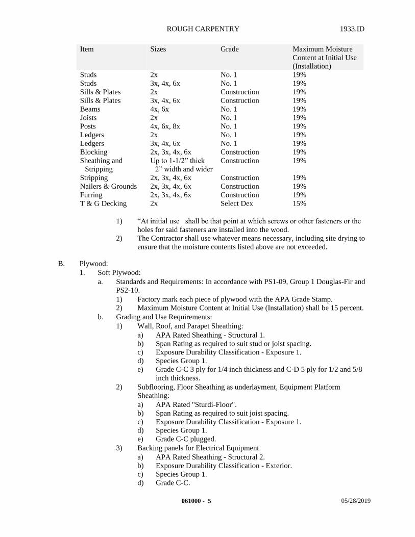
ROUGH CARPENTRY 1933.ID
Item Sizes Grade Maximum MoistureContent at Initial Use (Installation)
Studs 2x No. 1 19%Studs 3x, 4x, 6x No. 1 19%Sills & Plates 2x Construction 19%Sills & Plates 3x, 4x, 6x Construction 19%Beams 4x, 6x No. 1 19%Joists 2x No. 1 19%Posts 4x, 6x, 8x No. 1 19%Ledgers 2x No. 1 19%Ledgers 3x, 4x, 6x No. 1 19%Blocking 2x, 3x, 4x, 6x Construction 19%Sheathing and
StrippingUp to 1-1/2” thick
2” width and widerConstruction 19%
Stripping 2x, 3x, 4x, 6x Construction 19%Nailers & Grounds 2x, 3x, 4x, 6x Construction 19%Furring 2x, 3x, 4x, 6x Construction 19%T & G Decking 2x Select Dex 15%
1) “At initial use shall be that point at which screws or other fasteners or the
holes for said fasteners are installed into the wood.2) The Contractor shall use whatever means necessary, including site drying to
ensure that the moisture contents listed above are not exceeded.
B. Plywood:1. Soft Plywood:
a. Standards and Requirements: In accordance with PS1-09, Group 1 Douglas-Fir and PS2-10.1) Factory mark each piece of plywood with the APA Grade Stamp.2) Maximum Moisture Content at Initial Use (Installation) shall be 15 percent.
b. Grading and Use Requirements:1) Wall, Roof, and Parapet Sheathing:
a) APA Rated Sheathing - Structural 1.b) Span Rating as required to suit stud or joist spacing.c) Exposure Durability Classification - Exposure 1.d) Species Group 1.e) Grade C-C 3 ply for 1/4 inch thickness and C-D 5 ply for 1/2 and 5/8
inch thickness.2) Subflooring, Floor Sheathing as underlayment, Equipment Platform
Sheathing:a) APA Rated "Sturdi-Floor".b) Span Rating as required to suit joist spacing.c) Exposure Durability Classification - Exposure 1.d) Species Group 1.e) Grade C-C plugged.
3) Backing panels for Electrical Equipment.a) APA Rated Sheathing - Structural 2.b) Exposure Durability Classification - Exterior.c) Species Group 1.d) Grade C-C.
061000 - 5 05/28/2019
ROUGH CARPENTRY 1933.ID
e) Shall be 3/4 inch minimum thickness.4) Backing panels for Telecommunication Equipment:
a) APA Rated Sheathing - Structural 2.b) Exposure Durability Classification - Exterior.c) Species Group 1.d) Grade A-B.e) Shall be 3/4 inch minimum thickness.
2.3 FINISHES
A. Preservative Treatment:1. Pressure Treat Wood and Plywood, with CARB Complying, EPA Registered,
preservatives in accordance with AWPA Standards “U”, “T”, and “P”.a. Do not use material that does not comply with the requirements for untreated
material.b. After treatment, kiln-dry wood to a maximum moisture content of 19 percent.c. After treatment, dry plywood to a maximum moisture content of 15 percent.d. Factory mark each treated item with the treatment quality mark of an Independent
Inspection Agency approved by the ALSC Treated Wood Program.2. Non-pressure treat Wood and Plywood, with CARB Complying, EPA Registered
preservatives in accordance with AWPA Standards “U”, “T”, “P” and “N”.
B. Fire Retardant Treatment:1. Fire Retardant Treat Wood and Plywood with pressure treatment materials that comply
with performance requirements of AWPA C20 for Wood and AWPA C27 for Plywood.a. Use Exterior Type.b. Use treatment for which chemical manufacturer publishes physical properties of
treated wood after exposure to elevated temperatures when tested by a qualified independent testing agency and is acceptable to Fire and Life Safety authorities.
c. Use treatment that does not promote corrosion of metal fasteners.d. After treatment, kiln-dry wood to a maximum moisture content of 19 percent.e. After treatment, dry plywood to a maximum moisture content of 15 percent.f. Factory mark each treated item with the treatment quality mark of an Independent
Inspection Agency.
2.4 ACCESSORIES
A. Fasteners: All types shall comply with standards and dimensions of the latest edition of NDS. All types of fasteners exposed to wet or exterior conditions, in-ground contact, in pressure or preservative treated woods, in concrete or masonry, or in an area of high relative humidity shall be hot-dipped galvanized in accordance with ASTM A 153 "Specification for Zinc Coating (Hot Dip) on Iron and Steel Hardware".1. Nails: Common wire nails or spikes complying with ASTM F 1667 "Specification for
Friven Fasteners: Nails, Spikes, and Staples", and CBC Section 2304.9. Box nails and sinker nails are not permitted. Vinyl coating is permitted on common nails.
2. Bolts: Steel bolts complying with ASTM A 307 "Specification for Carbon Steel Bolts and Stds, 60,000 PSI Tensile Strength", Grade A, hex head.
061000 - 6 05/28/2019
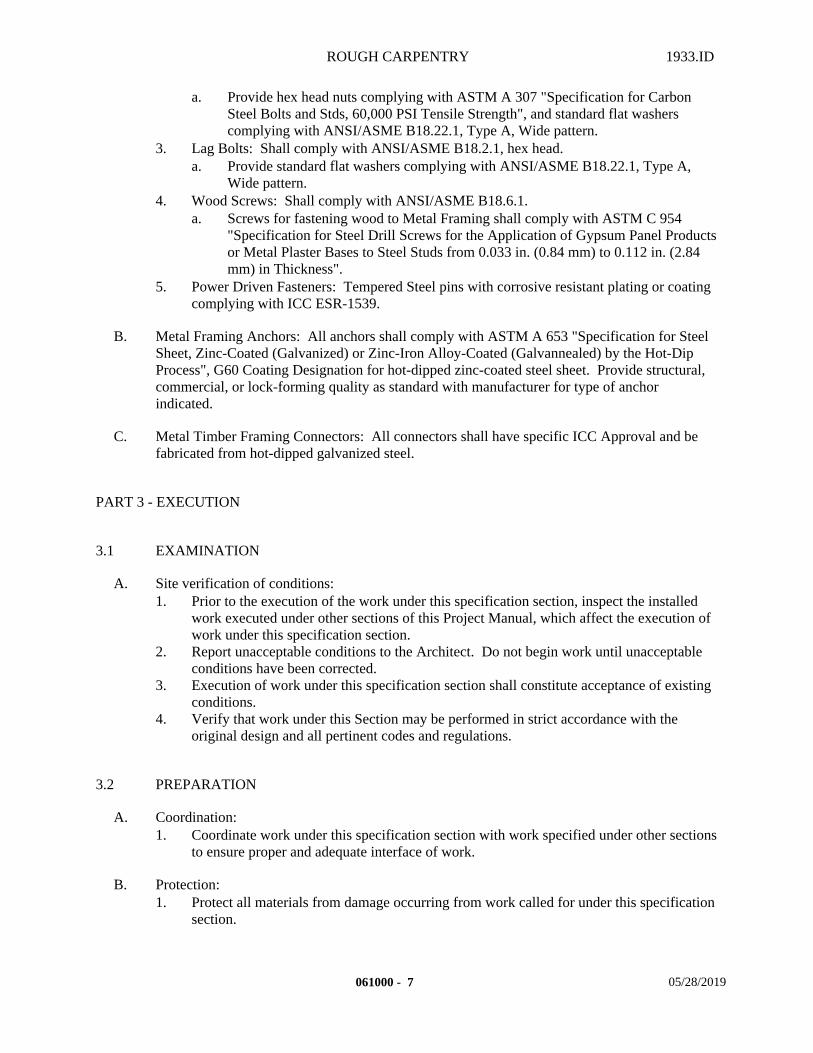
ROUGH CARPENTRY 1933.ID
a. Provide hex head nuts complying with ASTM A 307 "Specification for Carbon Steel Bolts and Stds, 60,000 PSI Tensile Strength", and standard flat washers complying with ANSI/ASME B18.22.1, Type A, Wide pattern.
3. Lag Bolts: Shall comply with ANSI/ASME B18.2.1, hex head.a. Provide standard flat washers complying with ANSI/ASME B18.22.1, Type A,
Wide pattern.4. Wood Screws: Shall comply with ANSI/ASME B18.6.1.
a. Screws for fastening wood to Metal Framing shall comply with ASTM C 954 "Specification for Steel Drill Screws for the Application of Gypsum Panel Products or Metal Plaster Bases to Steel Studs from 0.033 in. (0.84 mm) to 0.112 in. (2.84 mm) in Thickness".
5. Power Driven Fasteners: Tempered Steel pins with corrosive resistant plating or coating complying with ICC ESR-1539.
B. Metal Framing Anchors: All anchors shall comply with ASTM A 653 "Specification for Steel Sheet, Zinc-Coated (Galvanized) or Zinc-Iron Alloy-Coated (Galvannealed) by the Hot-Dip Process", G60 Coating Designation for hot-dipped zinc-coated steel sheet. Provide structural, commercial, or lock-forming quality as standard with manufacturer for type of anchor indicated.
C. Metal Timber Framing Connectors: All connectors shall have specific ICC Approval and be fabricated from hot-dipped galvanized steel.
PART 3 - EXECUTION
3.1 EXAMINATION
A. Site verification of conditions:1. Prior to the execution of the work under this specification section, inspect the installed
work executed under other sections of this Project Manual, which affect the execution of work under this specification section.
2. Report unacceptable conditions to the Architect. Do not begin work until unacceptable conditions have been corrected.
3. Execution of work under this specification section shall constitute acceptance of existing conditions.
4. Verify that work under this Section may be performed in strict accordance with the original design and all pertinent codes and regulations.
3.2 PREPARATION
A. Coordination:1. Coordinate work under this specification section with work specified under other sections
to ensure proper and adequate interface of work.
B. Protection:1. Protect all materials from damage occurring from work called for under this specification
section.
061000 - 7 05/28/2019
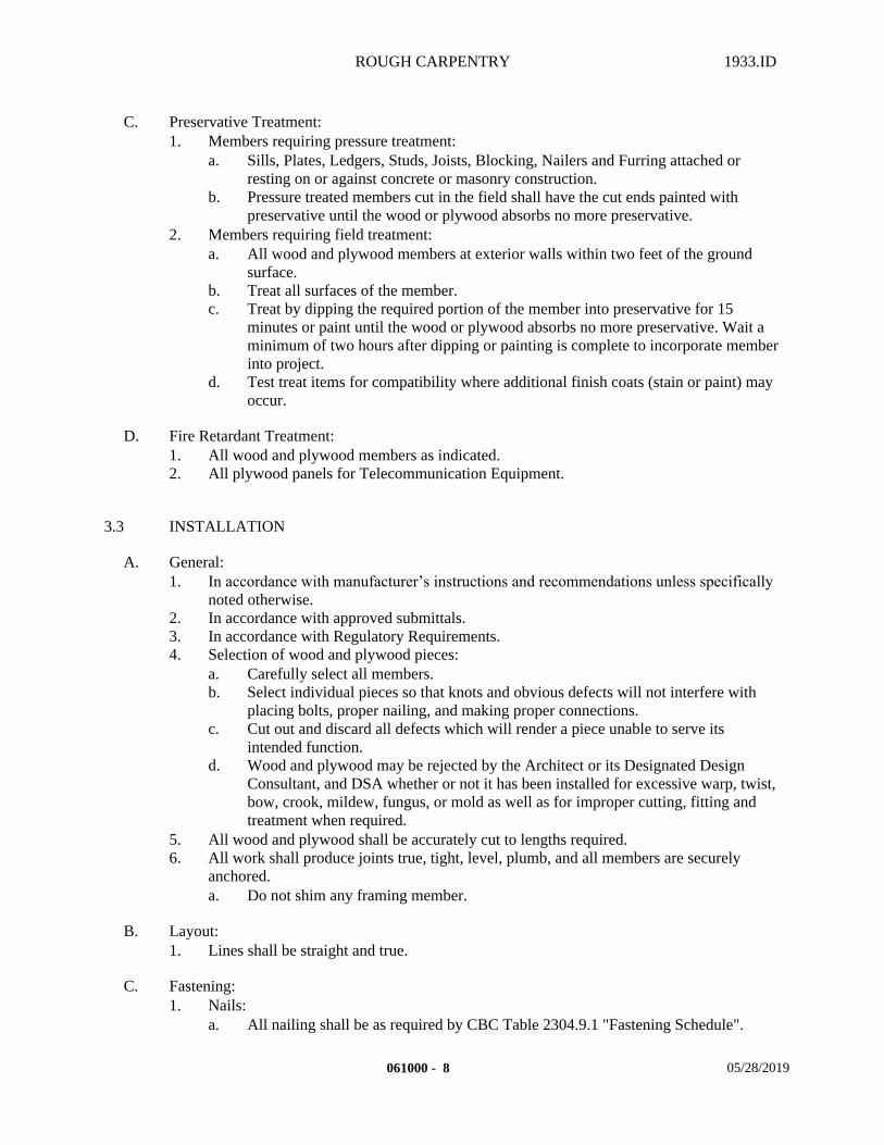
ROUGH CARPENTRY 1933.ID
C. Preservative Treatment:1. Members requiring pressure treatment:
a. Sills, Plates, Ledgers, Studs, Joists, Blocking, Nailers and Furring attached or resting on or against concrete or masonry construction.
b. Pressure treated members cut in the field shall have the cut ends painted with preservative until the wood or plywood absorbs no more preservative.
2. Members requiring field treatment:a. All wood and plywood members at exterior walls within two feet of the ground
surface.b. Treat all surfaces of the member.c. Treat by dipping the required portion of the member into preservative for 15
minutes or paint until the wood or plywood absorbs no more preservative. Wait a minimum of two hours after dipping or painting is complete to incorporate member into project.
d. Test treat items for compatibility where additional finish coats (stain or paint) may occur.
D. Fire Retardant Treatment:1. All wood and plywood members as indicated.2. All plywood panels for Telecommunication Equipment.
3.3 INSTALLATION
A. General:1. In accordance with manufacturer’s instructions and recommendations unless specifically
noted otherwise.2. In accordance with approved submittals.3. In accordance with Regulatory Requirements.4. Selection of wood and plywood pieces:
a. Carefully select all members.b. Select individual pieces so that knots and obvious defects will not interfere with
placing bolts, proper nailing, and making proper connections.c. Cut out and discard all defects which will render a piece unable to serve its
intended function.d. Wood and plywood may be rejected by the Architect or its Designated Design
Consultant, and DSA whether or not it has been installed for excessive warp, twist, bow, crook, mildew, fungus, or mold as well as for improper cutting, fitting and treatment when required.
5. All wood and plywood shall be accurately cut to lengths required.6. All work shall produce joints true, tight, level, plumb, and all members are securely
anchored.a. Do not shim any framing member.
B. Layout:1. Lines shall be straight and true.
C. Fastening:1. Nails:
a. All nailing shall be as required by CBC Table 2304.9.1 "Fastening Schedule".
061000 - 8 05/28/2019
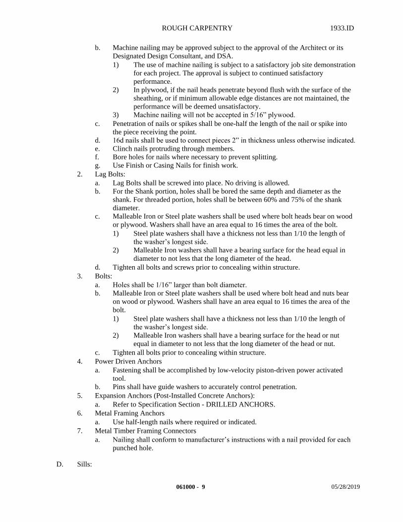
ROUGH CARPENTRY 1933.ID
b. Machine nailing may be approved subject to the approval of the Architect or its Designated Design Consultant, and DSA.1) The use of machine nailing is subject to a satisfactory job site demonstration
for each project. The approval is subject to continued satisfactory performance.
2) In plywood, if the nail heads penetrate beyond flush with the surface of the sheathing, or if minimum allowable edge distances are not maintained, the performance will be deemed unsatisfactory.
3) Machine nailing will not be accepted in 5/16” plywood.c. Penetration of nails or spikes shall be one-half the length of the nail or spike into
the piece receiving the point.d. 16d nails shall be used to connect pieces 2” in thickness unless otherwise indicated.e. Clinch nails protruding through members.f. Bore holes for nails where necessary to prevent splitting.g. Use Finish or Casing Nails for finish work.
2. Lag Bolts:a. Lag Bolts shall be screwed into place. No driving is allowed.b. For the Shank portion, holes shall be bored the same depth and diameter as the
shank. For threaded portion, holes shall be between 60% and 75% of the shank diameter.
c. Malleable Iron or Steel plate washers shall be used where bolt heads bear on wood or plywood. Washers shall have an area equal to 16 times the area of the bolt. 1) Steel plate washers shall have a thickness not less than 1/10 the length of
the washer’s longest side.2) Malleable Iron washers shall have a bearing surface for the head equal in
diameter to not less that the long diameter of the head. d. Tighten all bolts and screws prior to concealing within structure.
3. Bolts:a. Holes shall be 1/16” larger than bolt diameter.b. Malleable Iron or Steel plate washers shall be used where bolt head and nuts bear
on wood or plywood. Washers shall have an area equal to 16 times the area of the bolt. 1) Steel plate washers shall have a thickness not less than 1/10 the length of
the washer’s longest side.2) Malleable Iron washers shall have a bearing surface for the head or nut
equal in diameter to not less that the long diameter of the head or nut.c. Tighten all bolts prior to concealing within structure.
4. Power Driven Anchorsa. Fastening shall be accomplished by low-velocity piston-driven power activated
tool.b. Pins shall have guide washers to accurately control penetration.
5. Expansion Anchors (Post-Installed Concrete Anchors):a. Refer to Specification Section - DRILLED ANCHORS.
6. Metal Framing Anchorsa. Use half-length nails where required or indicated.
7. Metal Timber Framing Connectorsa. Nailing shall conform to manufacturer’s instructions with a nail provided for each
punched hole.
D. Sills:
061000 - 9 05/28/2019
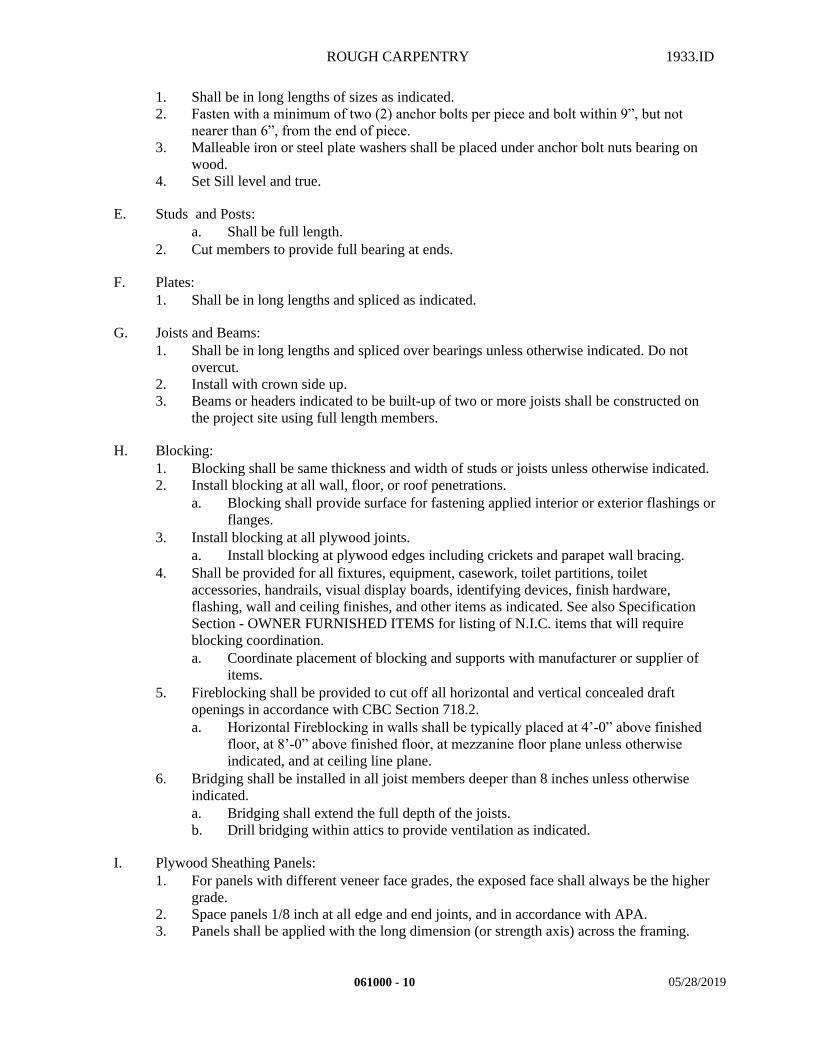
ROUGH CARPENTRY 1933.ID
1. Shall be in long lengths of sizes as indicated.2. Fasten with a minimum of two (2) anchor bolts per piece and bolt within 9”, but not
nearer than 6”, from the end of piece.3. Malleable iron or steel plate washers shall be placed under anchor bolt nuts bearing on
wood.4. Set Sill level and true.
E. Studs and Posts:a. Shall be full length.
2. Cut members to provide full bearing at ends.
F. Plates:1. Shall be in long lengths and spliced as indicated.
G. Joists and Beams:1. Shall be in long lengths and spliced over bearings unless otherwise indicated. Do not
overcut.2. Install with crown side up.3. Beams or headers indicated to be built-up of two or more joists shall be constructed on
the project site using full length members.
H. Blocking:1. Blocking shall be same thickness and width of studs or joists unless otherwise indicated.2. Install blocking at all wall, floor, or roof penetrations.
a. Blocking shall provide surface for fastening applied interior or exterior flashings or flanges.
3. Install blocking at all plywood joints.a. Install blocking at plywood edges including crickets and parapet wall bracing.
4. Shall be provided for all fixtures, equipment, casework, toilet partitions, toilet accessories, handrails, visual display boards, identifying devices, finish hardware, flashing, wall and ceiling finishes, and other items as indicated. See also Specification Section - OWNER FURNISHED ITEMS for listing of N.I.C. items that will require blocking coordination.a. Coordinate placement of blocking and supports with manufacturer or supplier of
items.5. Fireblocking shall be provided to cut off all horizontal and vertical concealed draft
openings in accordance with CBC Section 718.2.a. Horizontal Fireblocking in walls shall be typically placed at 4’-0” above finished
floor, at 8’-0” above finished floor, at mezzanine floor plane unless otherwise indicated, and at ceiling line plane.
6. Bridging shall be installed in all joist members deeper than 8 inches unless otherwise indicated.a. Bridging shall extend the full depth of the joists.b. Drill bridging within attics to provide ventilation as indicated.
I. Plywood Sheathing Panels:1. For panels with different veneer face grades, the exposed face shall always be the higher
grade.2. Space panels 1/8 inch at all edge and end joints, and in accordance with APA.3. Panels shall be applied with the long dimension (or strength axis) across the framing.
061000 - 10 05/28/2019
ROUGH CARPENTRY 1933.ID
4. Fasten from the field of the panel first and then to the ends and edges to reduce stressing of the panel surfaces.
5. Center all joints over bearing supports.6. Wall panels shall continue uninterrupted by ceilings or soffits from floor to floor or roof
unless otherwise indicated.
J. Sheathing:1. Shall be in accordance with the following:
a. Wall Sheathing: CBC Section 2304.6 and Table 2304.6 and Table 2304.6.1.b. Floor and Roof Sheathing: CBC Section 2304.7.c. Structural Floor Sheathing: CBC Section 2304.7.1.d. Structural Roof Sheathing: CBC Section 2304.7.2.e. Lumber Decking: CBC Section 2304.8.
K. Nailers and Grounds:1. Shall be installed as indicated and where required for attaching other work.2. Form to shapes indicated.3. Coordinate locations with other work involved.4. Provide nailers at all flashing and edge terminations when required by roofing
manufacturer for metal and concrete roof decks. When the roof system is required to be Class A use fire-retardant treated wood.
5. Provide permanent Grounds of dressed, pressure-preservative-treated, Key-beveled wood and of thickness required to bring face of ground to exact finish thickness of finish material. Remove temporary grounds when no longer required.
L. Furring and Stripping1. Shall be installed as indicated and where required to provide fastening material or space
for the passage of pipes, conduits, etc. not accommodated including ceiling stripping.
M. Sealant:1. When indicated, Primer shall be in accordance with sealant manufacturer
recommendations.2. When indicated, Joint Sealer shall be in accordance with Specification Section -
SEALANTS.
3.4 CONSTRUCTION
A. Draftstopping:1. Shall be provided in floor, attic, and ceiling areas in accordance with CBC Section 718.3
and 718.4.
B. Pipes:1. Frame to avoid cutting or drilling for passage of pipes, ducts, and conduit.2. Follow criteria as indicated for cutting or drilling. Unusual edge distances and awkward
spacing and sizes shall be brought to the Architects attention for remedy.
C. Chimneys and Flues:1. Keep all framing 2 inches away from chimney or flues in accordance with CBC Section
2304.5.
061000 - 11 05/28/2019
ROUGH CARPENTRY 1933.ID
D. Cant Strips and Crickets:1. Shape to sizes indicated.2. Rigidly fasten to construction. 3. Block all joints of plywood panel construction.4. Form neat and mitered corners.
E. Temporary Enclosures:1. Provide and maintain all barricades and enclosures required to protect the work in
progress.
F. Shoring or Bracing:1. Shore or brace for temporary support of all work as required during the construction
period except any shoring and bracing specified and included under other sections of this Project Manual.
G. Wood Curbs for Equipment:1. Construct all wood curbs for roof mounted equipment.2. Provide all miscellaneous blocking, bracing, supports, and other wood items to
complete the work.
3.5 FIELD QUALITY CONTROL
A. Site Tests:1. As required by Regulatory Requirements.2. Project Inspector shall verify by means of a handheld moisture content meter that all
wood and plywood supplied at the time of incorporation into structure(s) has met applicable moisture content requirements.
3. Project Inspector shall test all stud cavity walls to ensure that studs are a maximum of 19 percent moisture content prior to any other construction that encloses the wall cavity.
B. Inspection:1. As required by Regulatory Requirements.2. Schedule inspections and notify the Architect, Project Inspector and any other regulatory
agencies of the time at least 48 hours prior to the inspection.3. No work shall be without the inspections required by Regulatory Requirements.
3.6 CLEANING
A. Removal of Debris:1. Remove all Wood, including form lumber, chips, shavings and sawdust in or on the
ground from the areas inside buildings. Do not bury debris in fill.
END OF SECTION
061000 - 12 05/28/2019
MODULAR CASEWORK 1933.ID
SECTION 064123 – MODULAR CASEWORK
PART 1 - GENERAL
1.1 SUMMARY
A. This Section includes the following:1. Provide all material, labor, equipment and services necessary to completely install all
Modular Casework materials, accessories and other related items necessary to complete the Project as indicated by the Contract Documents.a. Plastic laminate-faced casework.b. Adjustable shelf supports:Metal Shelf Standardsc. Plastic Laminate countertops.
B. Related Sections: The following Sections contain requirements that relate to this Section:1. ALL DIVISION 00 SPECIFICATION SECTIONS.2. ALL DIVISION 01 SPECIFICATION SECTIONS.3. 03 15 14 DRILLED ANCHORS4. 03 30 00 CAST-IN-PLACE CONCRETE5. 05 12 00 STEEL AND FABRICATIONS (Steel supports for modular casework)6. 06 10 00 ROUGH CARPENTRY7. 09 22 16 METAL FRAMING8. 09 29 00 GYPSUM BOARD9. 09 65 10 RESILIENT BASE AND ACCESSORIES10. 09 65 19 RESILIENT TILE11. 09 91 00 PAINTING12. 10 05 00 MISCELLANEOUS SPECIALTIES13. ALL SPECIFICATION SECTIONS IN THE FACILITY SERVICES SUBGROUP.
1.2 REFERENCES
A. Standards:1. In accordance with the following standards:
a. BHMA BHMA stands for Builders Hardware Manufacturers Associates, Inc.b. NAAWS "North American Architectural Woodwork Standards", Latest Edition,
including latest amendments, by the Architectural Woodwork Institute, Architectural Woodwork Manufacturers Association of Canada, and the Woodwork Institute.
c. NEMA National Electrical Manufacturers' Associates, Publication Number LD3, latest-edition
d. NIST National Institute of Standards and Technologye. NWMA "Industrial Standard" National Woodwork Manufacturer's Association.f. PS Product Standard of the U. S. Department of Commerceg. WI Woodwork Institute.
064123 - 1 05/29/2019
MODULAR CASEWORK 1933.ID
1.3 DEFINITIONS
A. Refer to NAAWS.
B. Exposed Portions:1. Face members and edges of cabinets (cabinet fronts), such as face plates, drawer fronts,
door fronts, front edge of shelves. 2. Interior faces of cabinet doors. 3. Underside of bottoms of upper cabinets, 48" above finished floor.4. Cabinet tops:
a. Under 72" above finish floor.b. Visible from upper building level.
5. Interior surfaces (including top, bottom, and front of shelves) of open cabinets or cabinets with glass doors.
6. All surfaces of exposed shelves.7. All surfaces exposed to view.
C. Semi-Exposed Portions:1. Cabinet divisions, shelves, insides of drawers, and any other cabinet members which
cannot be seen when door or drawers are closed.
D. Concealed Portions:1. Cabinet framing that cannot be seen, such as web frame members, sleepers, dust panels,
toe strips covered with resilient base.
E. Shelving:1. Top and bottom surfaces. Face surfaces are the front and rear edges.
a. Ends are the left/right edges as you face the cabinet.2. The bottom surface material of all Upper Cabinets attached to walls shall be considered a
shelf and manufactured as a shelf.
F. Quality Assurance Options:1. Certified Compliance Program (CCP):
a. The CCP is an established discipline of quality control, for use in conjunction with the NAAWS, which provides a non-biased means of confirming conformance to a project's drawings and specifications.
b. Contractor to provide field inspection by WI Director, additional to CCP requirements.
c. The Woodwork Manufacturer shall have no less than 5 years of production experience, similar to this project, whose qualifications indicate the ability to comply with the requirements of this Section.
d. The Woodwork Manufacturer must have at least one project in the past 5 years where the value of the woodwork was within 20 percent of the cost of woodwork for this Project.
2. Monitored Compliance Program (MCP):a. The MCP is an established discipline of quality control, for use in conjunction
with the NAAWS, which provides a non-biased means of confirming conformance to a project's drawings and specifications,
064123 - 2 05/29/2019
MODULAR CASEWORK 1933.ID
b. Includes ongoing review/inspections of the project from its start to certification at completion.
c. The Woodwork Manufacturer shall have no less than 5 years of production experience, similar to this project, whose qualifications indicate the ability to comply with the requirements of this Section.
d. The Woodwork Manufacturer must have at least one project in the past 5 years where the value of the woodwork was within 20 percent of the cost of woodwork for this Project.
1.4 SYSTEM DESCRIPTION
A. Performance Requirements: It is the intention of this specification section and the drawings to form a guide for a complete and operable system. Any items not specifically noted but necessary for a complete and operable system shall be provided under this section. 1. All shelving must be manufactured according to NAAWS for Schools, Hospitals and
Library or Book Shelving. 50 lbs./SF.
1.5 SUBMITTALS
A. Submit in accordance with Specification Section - SUBMITTAL PROCEDURES:1. Product Data.
a. Submit manufacturer's full color range (including any standard and premium colors) for selection by the Architect.
b. Submit 2 copies of Manufacturer's current specifications for Modular Casework including all types of cabinets and accessories included in this section to the Architect for approval prior to fabrication.
2. Shop Drawings.a. Submit shop drawings from manufacturer detailing equipment assemblies and
indicating dimensions, weights, loadings, required clearances, method of field assembly, components, and location and size of each field connection.
b. Shop Drawing format in accordance with NAAWS Section 1, Submittals and WI's Certified Compliance Program.1) The shop drawings for the modular casework shall comply with and bear the
WI CERTIFIED COMPLIANCE LABEL.2) Each elevation of casework, each laminated plastic top, and each solid
surface top shall bear a WI CERTIFIED COMPLIANCE LABEL.3) Indicate spacing of all hardware accessories for Architect's review of layout.4) On casework and countertop elevations show the location of backing
required for attachment within walls.5) Before delivery to the jobsite the woodwork supplier shall provide a WI
CERTIFIED COMPLIANCE CERTIFICATE indicating the millwork products being supplied and Certifying that these products fully meet the requirements of the Grade or Grades specified.
6) At completion of installation the woodwork installer shall provide a WI CERTIFIED COMPLIANCE CERTIFICATE indicating the products installed, and Certifying that the installation of these products fully meets the requirements of the Grade or Grades specified.
064123 - 3 05/29/2019
MODULAR CASEWORK 1933.ID
7) All fees charged by the Woodwork Institute for their Certified Compliance Program are the responsibility of the millwork manufacturer and/or installer and shall be included in their bid
3. Samples.a. Provide nominal 2" x 3" sample chains of manufacturer's non-premium and
premium laminate color selection lines.1) Submit color samples of Manufacturer's full color and pattern range
(including wood grains) of non-premium and premium priced High Pressure Decorative Laminate to the Architect for color selection prior to fabrication.a) See drawings for high pressure decorative laminate color selection.
2) Submit color samples of high density overlay thermal-fused melamine for color selection by the Architect.a) Samples shall be equivalent to SELPLY products, from their full
color range selection chain of colors.3) Provide finish color selection samples of Pilaster Standard. Specified
colors subject to change.b. Mock-up as described elsewhere in this section.
4. Quality Assurance/Control Submittals:a. Certificates:
1) Submit three (3) copies of the following:a) Before delivery to the jobsite, the modular cabinetwork supplier shall
issue a WI CERTIFIED COMPLIANCE CERTIFICATE indicating the modular cabinetwork products and/or fabrication of products to be furnished for this project shall meet fully all the requirements of the grade or grades specified.
b) Upon completion of inspection of installation by WI Inspector, a WI CERTIFIED COMPLIANCE CERTIFICATE shall be furnished for the installation.
2) Submit three (3) copies of a letter on Contractor's Letterhead certifying work provided, meets or exceeds, the requirements of this Section.
b. Labels:1) Each plastic laminate countertop supplied shall bear the WI CERTIFIED
COMPLIANCE LABEL.
1.6 QUALITY ASSURANCE
A. Qualifications:1. Material Qualifications:
a. Grades as indicated on the drawings in accordance with the specifications, rules and details or casework of the NAAWS Sections 5 "Finishing", 10 "Casework", and 11 "Countertops", unless the drawings and these specification modify said standards.1) See Appendix "A" for "Cabinet Design Series" (CDS) Number System used
on Modular Casework Schedule.b. Laminated Plastic Countertops, Splashes, and Wall Paneling in accordance with
NAAWS Section 11 "Countertops".2. Installer Qualifications:
a. Engage an experienced Installer who has successfully completed three (3) projects of similar scope and size to that indicated for this Project.
064123 - 4 05/29/2019
MODULAR CASEWORK 1933.ID
3. Manufacturer/Supplier Qualifications:a. Firm(s) experienced in successfully producing/supplying products similar to that
indicated for this Project, with sufficient production/supply capacity to produce/supply required units without causing delay in the work.
b. All modular Cabinet Work must be done by a Single Source WI licensed manufacturer and be able to provide a WI Certified Compliance Certificate.
c. Participation in Woodwork Institute Quality Assurance Program:1) If supplier is WI Member Licensee in good standing:
a) Comply with WI CERTIFIED COMPLIANCE PROGRAM (CCP).b) Provide WI Director to inspect installation on-site.
2) If supplier is not WI Member Licensee in good standing:a) Comply with WI MONITORED COMPLIANCE PROGRAM
(MCP).
B. Regulatory Requirements:1. In accordance with Specification Section - REGULATORY REQUIREMENTS, and the
following:a. CARB Materials and equipment used for this Project shall comply with the
current applicable regulations of the California Air Resources Board (CARB) and the Environmental Protection Agency (EPA), in the area where the project is located.
b. CBC All hardware for casework shall meet CBC Section 11B-309.4 and 11B-811.4.
C. Meetings:1. Pre-Installation: Scheduled by the Contractor prior to the start of work.
a. Coordinate the work with all other related work b. identify potential problems that may impede planned progress and proper
installation of work regarding quality of installation and warranty requirements.c. Review the locations of backing required for casework installation as shown on the
casework shop drawings and the Contract Documents.d. Review the method of attachment of the backing to the wall system as shown on
the Contract Documents.2. Progress: Scheduled by the Contractor during the performance of the work.
a. Review for proper installation of work progress.b. Identify any installation problems and acceptable corrective measures.c. Identify any measures to maintain or regain project schedule if necessary.
3. Completion: Scheduled by the Contractor upon proper completion of the work.a. WI Inspector, Project Inspector, and the Architect shall inspect and identify any
problems that may impede issuance of warranties or guaranties.b. Maintain installed work until the Notice of Substantial Completion has been
executed.
1.7 DELIVERY, STORAGE, AND HANDLING
A. Packing, Shipping, Handling, and Unloading: 1. Products shall be handled in such a manner as to assure that they are free from dents,
scratches and other damage.
B. Acceptance at Site:
064123 - 5 05/29/2019
MODULAR CASEWORK 1933.ID
1. Hardware products (not already applied) must be in manufacturer's original unopened containers with labels indicating brand name, model, and grade.
2. Casework products must be free from scratches, gouges, or any other marring or discoloration.
3. Damaged products will not be accepted.
C. Storage and Protection: 1. Products shall be stored above ground on level platforms, six (6) inches above ground,
allowing air circulation under stacked units, in compliance with PROJECT CONDITIONS below.a. Cover materials with protective waterproof covering providing for adequate air
circulation and ventilation.
1.8 PROJECT CONDITIONS
A. Environmental Requirements:1. Humidity and Temperature: Maintain humidity and temperature in the space to receive
products between 45 percent to 65 percent at a temperature of 60 degrees to 90 degrees F. Equilibrium Moisture Content of the wood product conditions shall be maintained between 8 percent and 12 percent. Maintain these requirements for four (4) days minimum prior, during, and following installation in accordance with manufacturer's written recommendations. Inform the Owner of humidity requirements for products installed and maintain until Substantial Completion and the turn-over of the building or facility to the Owner.
1.9 WARRANTY
A. Contractor's General Warranty:1. In accordance with Specification Section - WARRANTIES.
B. Manufacturer's Warranty:1. In accordance with manufacturer's written standard warranty:
a. Warranty Period One (1) Year.
C. Installer's Warranty:1. In accordance with the terms of the Specification Section - WARRANTIES
a. Warranty Period One (1) Year.
064123 - 6 05/29/2019
MODULAR CASEWORK 1933.ID
PART 2 - PRODUCTS
2.1 MANUFACTURERS
A. These products listed herein establish the size, pattern, color range and function selected by the Architect for this Project. Manufacturers that are listed as acceptable alternative manufacturers and substitutions must still comply with the requirements of this project and the products listed in order to be approved as an equivalent during the Submittal Process. If the acceptable alternative manufacturers listed or substitutions are not approved during the Submittal Process due to non-compliance with the contract documents, then the Contractor shall submit product specified. 1. Specified product manufacturers:
a. High Pressure Decorative Laminate: WILSONART.1) Cabinet Liner Series Type CLS.
b. Low Pressure Thermal-fused:1) AMERICAN LAMINATE, PANELAM, or ROSEBURG FOREST
PRODUCTS.c. Cabinetry Hardware: See Cabinet Hardware Schedule.
B. Products from other manufacturers not listed must submit in accordance with Specification Section - SUBSTITUTION PROCEDURES.
2.2 CABINET MATERIALS
A. Exposed Materials:1. General:
a. In accordance with NAAWS Section 4 - Sheet Products. b. Minimize seams.
2. Laminate Systems: a. Decorative Laminate:
1) Horizontal Surfaces: Post-formed Grade HGP (0.042").2) Vertical Surfaces: Grade VGP (0.027").
a) Pattern direction: Vertical, unless otherwise noted. b. Edgebanding:
1) Rigid PVC extrusions, through color with satin finish, 3 mm thick at doors and drawer fronts, 0.5 mm thick elsewhere. Color to match adjacent material.
B. Semi-Exposed Materials:1. Cabinet Liner:
a. Complying with requirements of NEMA LD-3, Grade CLS.2. Edgebanding:
a. Rigid PVC extrusions, through color with satin finish. 1) Typical: 0.5 mm thick.2) Front edge of shelves and all edges of drawers: 3 mm.
C. Concealed Materials:
064123 - 7 05/29/2019
MODULAR CASEWORK 1933.ID
1. Particleboard: ANSI A208.1, Grade M-2.a. 44-50 lb Industrial Grade core. b. Thickness Swell max: 5.5 percent.
2. Veneer Core Hardwood Plywood (VCHP):a. No internal voids.b. MDF cross bands to limit telegraphing of core grain is acceptable.
D. Fasteners:1. Per NAAWS.2. Corrosion resistant fasteners throughout the assembly of modular casework.
2.3 FABRICATION
A. General:1. In accordance with NAAWS Section 10 - Casework, Custom Grade, as amended by the
Contract Documents.2. Interface Style, Frameless: Flush Overlay.3. Seismic Force Requirements - The types of construction approved by WI that meet CBC
Title 24 seismic force requirements are: Lock Joint, Dowled, Dowled / Screwed Construction, Rabbeted Construction, Confirmat Screws, Fully Plowed-in Back, and Backs Screwed on in rabbeted ends, tops, and bottoms. The exact method for seismic force construction is available from WI.
4. Construct openings and backing as required for work done under Division 22 PLUMBING (sinks, plumbing, etc.) and Division 26 ELECTRICAL (outlets, switches, wiring, etc).a. Exposed Edges: All exposed edges shall be sealed; including sink cut-outs &
bottom edges of front edges.5. Cabinets ganged together or attached to the wall shall be attached with countersunk
screws to prevent binding of shelves when provided later.6. Any vertical or horizontal plane surface less than four (4) foot wide and twelve (12) foot
long shall be faced with one continuous laminate sheet with the intent to minimize the number of laminate seams throughout the work, in compliance with NAAWS Section 8 "Wall Surfacing".
B. Cabinets:1. Cabinet box:
a. Bottoms and Ends of Cabinets: 3/4-inch particleboard.b. Tops of Wall Cabinets and Tall Cabinets: 3/4-inch particleboard.c. Backs of Cabinets: Particleboard.
1) Concealed Backs: 1/4" minimum.2) Exposed Backs: 1/2" minimum.
2. Filler Strips: a. Provide as needed to close spaces between cabinets and walls, ceilings, and
indicated equipment. Fabricate from same material and with same finish as cabinets.
3. Shelving System:a. Shelf Support System:
1) Bored Hole Shelf Rest Systems: a) 5mm diameter holes drilled approximately 8 mm deep, 32 mm o.c.
064123 - 8 05/29/2019
MODULAR CASEWORK 1933.ID
b) The front and rear row of holes shall be 37 mm from the front and rear edge of the cabinet.
c) Provide full cabinet height holes at 32 mm o.c. in each row to allow maximum flexibility of the user to arrange shelves.
2) Provide four clips for each shelf.b. Shelves: Veneer Core Hardwood Plywood.
1) Span less than 25-inches: 3/4-inch.2) Span greater than 25-inches: 1-inch.3) Library shelves of any span: 1-inch thick.
4. Doors:a. Core material: Particleboard.b. Doors 48 inches high or less: 3/4 inch thick.c. Doors more than 48 inches high: 1-1/8 inches thick.d. Doors more than 80 inches high: 4 hinges, minimum. e. Stiles and Rails of Glazed Doors: 3/4 inch thick.f. Let in 1/8" reveals for institutional hinges.
5. Drawers:a. Drawer Fronts: 3/4-inch Particleboard.b. Drawer Sides and Backs: 1/2-inch Veneer-Core Hardwood Plywood.
1) Joined using Confirmat Screws in lieu of dowels. c. Drawer Bottoms: 1/2-inch Veneer-Core Hardwood Plywood glued and dadoed
into front, back, and sides of drawers.d. File Drawers / Lateral File Drawers:
1) Sides: 3/4-inch Veneer-Core Hardwood Plywood. 2) Bottoms: 5/8 inch Veneer-Core Hardwood Plywood. 3) Sides and bottoms shall be secured using 2-inch Confirmat screws.
e. Security Panels: 1/2-inch Veneer-Core Hardwood Plywood.1) Provide Security Panels above and below all locking drawers.
f. All drawers and doors shall be locked, keyed alike in each room and with building masters and grand master.1) Each room shall be keyed alike:
a) Provide 4 keys per lock.b) Provide 6 master keys.
C. Countertops:1. General: In accordance with NAAWS Section 11 -- Countertops, as amended by the
Contract Documents.2. Laminate Countertops:
a. Standard: In accordance NEMA standard LD-3.b. Strength: 3/16 inch maximum deflection with 150 pound load at midspan.c. Surface Material: Plastic Laminate.d. Backing Material:Cabinet Liner.e. Core: 3/4-inch Particleboard.f. Front Edge: Self-edge build-up with drip groove edge. g. Back Splash: 6 inch integral cove splash, unless otherwise indicated on the
drawings.h. End Splash: 6 inch butt end splash, unless otherwise indicated on the drawings.i. Top of Splash: Square Edge.j. Exposed Edges: All exposed edges shall be sealed; including sink cut-outs &
bottom edges of front edges.
064123 - 9 05/29/2019
MODULAR CASEWORK 1933.ID
D. Hardware:1. See schedule at the end of this section for typical cabinet hardware.2. Hardware shall be furnished and installed as required to provide a complete casework
installation for overlay construction, unless noted otherwise.3. Provide metal strike at locks.4. Finish: BHMA 626 (26D), unless otherwise noted.
PART 3 - EXECUTION
3.1 EXAMINATION
A. Site verification of conditions:1. Prior to the execution of the work under this specification section, inspect the installed
work executed under other specification sections of this Project Manual, which affect the execution of work under this specification section.
2. Report unacceptable conditions to the Architect. Do not begin work until unacceptable conditions have been corrected.
3. Execution of work under this specification section shall constitute acceptance of existing conditions.
3.2 PREPARATION
A. Coordination:1. Coordinate work under this specification section with work specified under other
specification sections to ensure proper and adequate interface of work specified under this specification section.
B. Protection:1. Protect all adjacent surfaces from drips, spray, air pollution of surrounding environment,
and other damage from work under this specification section.
C. Surface preparation:1. Prepare surface in accordance with manufacturer's written instructions and
recommendations.2. Clean substrates of substances (oil, grease, rolling compounds, incompatible primers,
loose mill scale, etc.) which could impair bond of materials specified within this section.
3.3 INSTALLATION
A. General:1. In accordance with manufacturer's written instructions and recommendations unless
specifically noted otherwise.a. Provide experienced, factory trained craftspeople under manufacturers direct
supervision.2. In accordance with approved submittals.3. In accordance with Regulatory Requirements.
064123 - 10 05/29/2019
MODULAR CASEWORK 1933.ID
4. The entire installation shall present a first class, workmanlike appearance, without open joints, tool marks or other blemishes, and subject to the Architect's approval.
5. Edges of cutouts, subject to excessive moisture, shall be sealed with a color-toned (for verification), water-resistant sealer before trim or sink rims are installed.
B. Layout:1. Set plumb, level, and to true lines as shown on the drawings.2. Filler panels and scribe strips or moldings, as required, shall be properly scribed to
adjacent work and securely attached to cabinets as indicated on the drawings.
C. Anchorage:1. The backs of the cabinets shall be secured to the wall backing.2. Refer to the Drawings for the backing and anchorage details.3. As a minimum, each cabinet shall be secured to the backing with a total of four #14
screws.
D. Cabinet Bases:1. Toe Kick: Cabinet base shall be set back from the face of the cabinet 3-inches, or as
indicated 2. Cabinet sides: Cabinet shall be set 3/8-inch back from the face of the cabinet.
3.4 FIELD QUALITY CONTROL
A. Inspection:1. Schedule WI inspection with a minimum of 7 days notice of planned installation.2. Schedule inspections and notify the Architect, Owner's Project Inspector and any other
regulatory agencies of the time at least 48 hours prior to the inspection.3. No work shall be without the inspections required by Regulatory Requirements.
3.5 ADJUSTING
A. Test and adjust carpentry hardware. Replace damaged or malfunctioning controls and equipment.
3.6 CLEANING
A. Clean in accordance with Specification - PROJECT CLOSEOUT.1. Clean any soiled surfaces immediately.2. In accordance with manufacturer's written instructions and recommendations.3. Finish shall be clean and ready for the application of any additional finishes.
3.7 PROTECTION
A. Protection from traffic: 1. Provide final protection and maintain conditions, in a manner acceptable to manufacturer
and installer, which ensures the work of this section being without damage or deterioration until the time of Substantial Completion.
064123 - 11 05/29/2019
MODULAR CASEWORK 1933.ID
3.8 SCHEDULES
A. Standard Cabinetry Hardware specified, or approved equivalent:1. Hinges: Institutional Hinges for Overlay doors, 2-3/4" five knuckle with hospital tips and
2-5/8" extended side panel wing:a. ROCKFORD PROCESS:
1) #374 for 3/4" x 3/4" thicknesses.2) #376 for 3/4" x 13/16" thicknesses.
2. Pulls (Steel Wire "U" Shaped - 4" centers, 1-1/4" Projection from face of drawer or door):a. JAMISON: SWP4-26D.
3. Locks (Hinged Doors and Drawers for Overlay Construction):a. COMP X NATIONAL: #C8053.b. Approved equivalent manufacturer:
1) OLYMPUS LOCK, INC. #DCN as required.c. Provide compatible strike.d. OLYMPUS LOCK, INC. #DCN as required. e. Approved equivalent manufacturer:
1) COMP X NATIONAL: #C8053.f. Provide compatible strike.
4. Adjustable Shelf Pilaster Standard and Shelf Supports:a. Pilaster Standard shall be KNAPE & VOGT #255, 19-gage x 5/8" wide x 3/16"
high.1) #255-WH (Epoxy-Coated White) at interior cabinet surface locations.2) #255-BRN (Brown) at exposed cabinet surface locations.
b. Shelf Supports shall be KNAPE & VOGT #239 ZC (Zinc Coated).5. Magnetic Catcher:
a. AMEROCK: #CM9783-AL.b. Approved equivalent manufacturer:
1) KNAPE AND VOGT: #918-AL.6. Exposed Fasteners: When exposed fasteners are used, provide zinc chromate coated
oval head, self-tapping phillips screws with grommet finishing washers, same finish as screws.
7. Joint Closure:a. PEMKO: #313AN.
8. Miscellaneous Hardware Items:a. HAFELE:
1) Bow Handles: #102.49.402.2) Miscellaneous: Dished Sleeves, screws, washers, nuts, threaded pins,
screw-in sleeves, shelf supports with locking screws, connecting fittings, & capped bolts.
END OF SECTION
064123 - 12 05/29/2019
WOOD DOORS 1933.ID
SECTION 081416 – WOOD DOORS
PART 1 - GENERAL
1.1 SUMMARY
A. This Section includes the following:1. Provide all material, labor, equipment and services necessary to completely install all
wood door materials, accessories and other related items necessary to complete the Project as indicated by the Contract Documents.
B. Related Sections: The following Project Manual Sections contain requirements that relate to this section:1. ALL DIVISION 00 SPECIFICATION SECTIONS.2. ALL DIVISION 01 SPECIFICATION SECTIONS.3. 05 12 00 STEEL AND FABRICATIONS4. 08 80 00 GLASS5. 09 22 16 METAL FRAMING6. 09 29 00 GYPSUM BOARD7. 09 91 00 PAINTING
1.2 REFERENCES
A. Standards:1. In accordance with the following standards:
a. AWS "Architectural Woodwork Standards", Latest Edition, including latest amendments, by the Architectural Woodwork Institute, Architectural Woodwork Manufacturers Association of Canada, and the Woodwork Institute.
b. BHMA Builders Hardware Manufacturers Association, Inc.c. CRSC California Referenced Standards Code, CCR, Part 12, Chapter 12-7-4
"FIRE-RESISTIVE STANDARDS - Fire Door Assembly Tests".d. NEMA National Electrical Manufacturers Association, LD-3, Latest Edition. e. NFPA National Fire Protection Association "Fire Doors and Windows" NFPA
No. 80.f. UL Underwriter's Laboratories "Fire Tests of Door Assemblies" (UL 10 (b) -
1970).g. WDMA Window and Door Manufacturers Association.h. WDMA I.S. 1A-04 "Industry Standard for Architectural Wood Flush Doors".i. WI Woodwork Institute.
1.3 SUBMITTALS
A. Submit in accordance with Specification Section - SUBMITTAL PROCEDURES:1. Product Data.
a. Submit manufacturer's literature describing products.2. Shop Drawings.
081416 - 1 05/29/2019
WOOD DOORS 1933.ID
a. Submit shop drawings from manufacturer detailing equipment assemblies and indicating dimensions, weights, loading, required clearances, method of field assembly, components, and location and size of each field connection.
b. Submit door type, details and location with reference to Architect's door mark and hardware group.
3. Samples.a. Provide samples of each door finish, in the species specified for the veneer.
4. Quality Assurance/Control Submittals:a. Test Reports:
1) Submit four (4) copies of testing laboratory's report indicating any fire labels that may be required.
b. Manufacturer's Written Instructions:1) Submit three (3) copies of manufacturer's written instructions.
c. Certificates:1) Submit three (3) copies of certificates.
a) Before delivery to the jobsite, the Wood Door supplier shall issue a WI CERTIFIED COMPLIANCE CERTIFICATE indicating the Wood Door products to be furnished for this project shall meet fully all the requirements of the grade or grades specified.
b) Upon completion of installation, a WI CERTIFIED COMPLIANCE CERTIFICATE shall be furnished for the installation.
c) Submit three (3) copies of a letter on Contractor's Letterhead certifying work provided, meets or exceeds, the requirements of this Section.
5. Closeout Submittals in accordance with the following:a. Maintenance Data in accordance with Specification Section - PROJECT
CLOSEOUT.b. Warranty in accordance with Specification Section - WARRANTIES.
1.4 QUALITY ASSURANCE
A. Qualifications:1. Installer Qualifications:
a. Engage an experienced Installer who has successfully completed three (3) projects of similar scope and size to that indicated for this Project.
b. Engage an experienced Installer who is certified in writing by the manufacturer listed herein as qualified to install manufacturer's product (or system) in accordance with manufacturer's warranty requirements.
2. Manufacturer/Supplier Qualifications:a. Firm experienced in successfully producing/supplying products similar to that
indicated for this Project, with sufficient production/supply capacity to produce/supply required units without causing delay in the work.
3. Testing Agency Qualifications:a. Testing Agency shall be approved and recognized by enforcing agency and provide
inspection of materials and workmanship during fabrication and assembly.
B. Regulatory Requirements:1. In accordance with Specification Section - REGULATORY REQUIREMENTS, and the
following:
081416 - 2 05/29/2019
WOOD DOORS 1933.ID
a. CARB Materials and equipment used for this Project shall comply with the current applicable regulations of the California Air Resources Board (CARB) and the Environmental Protection Agency (EPA), in the area where the project is located.
C. Meetings:1. Pre-Installation: Schedule d by the Contractor prior to the start of work.
a. Coordinate the work with other work being performed.b. Identify any potential problems that may impede planned progress and proper
installation of work regarding quality of installation and warranty requirements. 2. Progress: Scheduled by the Contractor during the performance of the work.
a. Review for proper installation of work progress.b. Identify any installation problems and acceptable corrective measures.c. Identify any measures to maintain or regain project schedule if necessary.
3. Completion: Scheduled by the Contractor upon proper completion of the work.a. Inspect and identify any problems that may impede issuance of warranties or
guaranties.b. Maintain installed work until the Notice of Substantial Completion has been
executed.
1.5 DELIVERY, STORAGE, AND HANDLING
A. Packing, shipping, handling, and unloading: 1. Products shall be individually wrapped. 2. Products shall be handled in such a manner as to assure that they are free from dents,
scratches and other damage.
B. Acceptance at Site: 1. Products must be in manufacturer's original unopened containers with labels (including
any fire labels) indicating brand name, model, and grade. 2. Damaged products will not be accepted.
C. Storage and protection: 1. Products shall be stored above ground on level platforms, six (6) inches above ground,
allowing air circulation under stacked units. a. Cover materials with protective waterproof covering providing for adequate air
circulation and ventilation.
1.6 PROJECT CONDITIONS
A. Environmental requirements:1. Temperature: Maintain ambient temperature in space to receive products between sixty
(60) degrees Fahrenheit and ninety (90) degrees Fahrenheit for seven (7) days prior, during, and seven (7) days minimum following installation. Inform the Owner of ambient temperature requirements for products installed and maintain until Substantial Completion and turn-over of the building or facility to the Owner.
081416 - 3 05/29/2019
WOOD DOORS 1933.ID
2. Humidity: Maintain humidity in space to receive products between 25 percent to 55 percent at 60 degrees F to 90 degrees F, and EMU (Equilibrium Moisture Content) conditions between 6 percent to 8 percent for four (4) days minimum prior, during, and following installation in accordance with manufacturer's written recommendations. Inform the Owner of humidity requirements for products installed and maintain until Substantial Completion and turn-over of the building or facility to the Owner.
B. Existing Conditions: 1. Examine site and compare it with the drawings and specifications. Thoroughly
investigate and verify conditions under which the work is to be performed. No allowance will be made for extra work resulting from negligence or failure to be acquainted with all available information concerning conditions necessary to estimate the difficulty or cost of the work.
2. Conduct work so as not to interfere unnecessarily with adjacent roads, streets, drives and walks.
1.7 WARRANTY
A. Contractor's General Warranty:1. In accordance with Specification Section - WARRANTIES.
B. Manufacturer’s Warranty:1. In accordance with manufacturer's written materials standard warranty:
a. Warranty Period Life of Installation.1) Doors shall be warranted for life of installation against warp or twist in
excess of 1/4" in any face including full diagonal.2) Replacement shall include finishing of new replacement door, hardware
damaged by malfunction of original door, and hanging in satisfactory operating condition.
C. Installer's Warranty:1. In accordance with the terms of the Specification Section - WARRANTIES:
a. Warranty period Five (5) years.
PART 2 - PRODUCTS
2.1 MANUFACTURED UNITS
A. Wood Doors: The goal is to match existing. If it can not be established what the existing adjacent door standards are, then follow the door characteristics below:1. Performance Duty Level: Extra Heavy Duty per ANSI /WDMA I.S.1A.2. Acoustical Performance:
a. Typical Wood Door Assemblies: STC 30 min. 3. Pre-finished Wood Veneer, 1-3/4" Solid Core, with stain grade wood veneer faced doors,
WI Premium Grade.a. Standard: Manufactured in accordance with Commercial Standards as amended and
recognized by the AWS.b. Core:
081416 - 4 05/29/2019
WOOD DOORS 1933.ID
1) Non-Rated Solid Core Doors:a) 5-ply particle board core bonded under pressure to stiles and rails.
c. Face Veneers:1) AWS - Match existing door finishes.
d. Edges:1) Same species of the face, sealed and matched for color with the face veneer.
e. Finish:1) Premium Grade, clear System No. 5 (Catalyzed Polyurethane).
f. Glass and Louver Frames:1) Molding and trim to be integral construction and flush with face sheet of
door.2) Glass thickness is specified in Specification Section – GLASS.
4. Pre-finished Wood Veneer, Solid Core, with opaque paint grade wood veneer faced doors, WI Premium Grade.a. Standard: Manufactured in accordance with Commercial Standards as amended and
recognized by the AWS.b. Core:
1) Non-Rated Solid Core Doors:a) 5-ply particle board core bonded under pressure to stiles and rails.
2) Fire-Rated Solid Core Doors:a) Mineral composition core meeting requirements of specified
standards.c. Face Veneers:
1) AWS Birch, rotary cut, flitches suitable for opaque finish.d. Edges:
1) Same species of the face, sealed and matched for color with the face veneer.e. Finish:
1) Field Painted Paint Grade.f. Glass and Louver Frames:
1) Molding and trim to be integral construction and flush with face sheet of door.
2) Glass thickness is specified in Specification Section – GLASS.
B. Hardware:1. Match existing adjacent hardware keying and finishes.2. Doors shall be pre-fit in field and provided with cut outs for hardware according to
templates and AWS.
2.2 FABRICATION
A. Shop Assembly: 1. All doors marked for opening numbers shown on the drawings and with protective
wrapping.a. Doors shall be Type I adhesive doors regardless of exposure.
081416 - 5 05/29/2019
WOOD DOORS 1933.ID
2.3 FACTORY FINISHING
A. General: Comply with referenced quality standard for factory finishing. Complete fabrication, including fitting doors for openings and machining for hardware that is not surface applied, before finishing.1. Finish faces, all four edges, edges of cutouts, and mortises. Stains and fillers may be
omitted on edges of cutouts, and mortises.
B. Finish doors at factory.
C. Finish doors at factory that are indicated to receive transparent finish.
D. Transparent Stained Finish:1. Grade: Premium.2. Staining: As selected by Architect from manufacturer's full range.
a. Do not stain over fire labels. 3. Finish: WI System No. 5 catalyzed polyurethane.4. Effect: Semifilled finish, produced by applying an additional finish coat to partially fill
the wood pores.5. Sheen: Satin.
PART 3 - EXECUTION
3.1 EXAMINATION
A. Site verification of conditions:1. Prior to the execution of the work under this specification section, inspect the installed
work executed under other sections of this Project Manual, which affect the execution of work under this specification section.
2. Report unacceptable conditions to the Architect. Do not begin work until unacceptable conditions have been corrected.
3. Execution of work under this specification section shall constitute acceptance of existing conditions.
3.2 PREPARATION
A. Coordination:1. Coordinate work under this specification section with work specified under other sections
to ensure proper and adequate interface of work.2. Examine opening and hardware schedules to verify proper coordination.
B. Protection:1. Protect all adjacent surfaces from drips, spray, air pollution of surrounding environment,
and other damage from work under this specification section.
C. Surface preparation:
081416 - 6 05/29/2019
WOOD DOORS 1933.ID
1. Prepare surface in accordance with manufacturer's written instructions and recommendations.
2. Clean substrates of substances (oil, grease, rolling compounds, incompatible primers, loose mill scale, etc.) which could impair bond of materials specified within this section.
3.3 INSTALLATION
A. General:1. In accordance with manufacturer's written instructions and recommendations unless
specifically noted otherwise.2. In accordance with approved submittals.3. In accordance with Regulatory Requirements.4. Set plumb, level, and square.
B. Layout:1. Lines shall be straight and true.
C. Non-Rated Doors:1. Clearance at jambs and heads: 1/8-inch.2. Per leaf clearance at meeting stiles for pairs of doors: 1/16-inch.3. Clearance from bottom of door to top of decorative floor finish or covering:
1/8-inch.4. Where threshold is shown or scheduled, provide 1/4-inch clearance from bottom of door
to top of threshold.
D. Install all finish hardware in strict accordance with the manufacturers written recommendations, eliminating all hinge-bound conditions and making all items smoothly operating and firmly anchored into position.
3.4 REPAIR / RESTORATION
A. Defective Work:1. Replace, rework or otherwise make good as required doors, finish, frames or hardware
found broken, damaged, disfigured or defaced.2. Incomplete, misaligned, or incorrectly located products will not be accepted.
3.5 CLEANING
A. Clean in accordance with Specification Section - PROJECT CLOSEOUT.1. Clean any soiled surfaces immediately.2. Finish shall be clean and ready for the application of any additional finishes.3. In accordance with manufacturer's written instructions and recommendations.
3.6 PROTECTION
A. Protection from traffic:
081416 - 7 05/29/2019
WOOD DOORS 1933.ID
1. Provide final protection and maintain conditions, in a manner acceptable to manufacturer and installer, which ensures the work of this section being without damage or deterioration until the time of Completion.
END OF SECTION
081416 - 8 05/29/2019
STOREFRONTS 1933.ID
SECTION 084100 – STOREFRONTS
PART 1 - GENERAL
1.1 SUMMARY
A. This Section includes the following:1. Provide all material, labor, equipment and services necessary to completely install all
materials, accessories and other related items necessary to complete the Project as indicated by the Contract Documents.
B. Related Sections: The following Project Manual Sections contain requirements that relate to this section:1. ALL DIVISION 00 SPECIFICATION SECTIONS.2. ALL DIVISION 01 SPECIFICATION SECTIONS.3. 03 30 00 CAST-IN-PLACE CONCRETE4. 05 12 00 STEEL AND FABRICATIONS5. 06 10 00 ROUGH CARPENTRY6. 08 14 16 WOOD DOORS7. 08 80 00 GLASS 8. 09 22 16 METAL FRAMING9. 09 29 00 GYPSUM BOARD10. ALL SPECIFICATION SECTIONS IN THE FACILITY SERVICES SUBGROUP.
a. Coordinate Storefront System to receive internal cabling for Facility Service Systems, including but not limited to:1) Electrical System.2) Intrusion Detection System.3) Access Control System.
1.2 REFERENCES
A. Standards:1. In accordance with the following standards:
a. AA Aluminum Association b. AAMA American Architectural Manufacturers Associationc. ADA Americans with Disabilities Actd. ADAAG Americans with Disabilities Act Accessibility Guidelines – "For
Buildings and Facilities". e. ANSI American National Standards Institutef. ASCE American Society of Civil Engineersg. AWS American Welding Society h. BHMA Builders Hardware Manufacturers Associationi. GANA Glass Association of North Americaj. NAAMM National Association of Architectural Metal Manufacturersk. SSPC The Society for Protective Coatings (formerly the Steel Structures
Painting Council)
084100 - 1 05/29/2019
STOREFRONTS 1933.ID
1.3 DEFINITIONS
A. Exterior and Interior Storefront Systems – indicated on the drawings as SF.
1.4 SYSTEM DESCRIPTION
A. General: Provide aluminum systems capable of withstanding loads and thermal and structural movement requirements indicated without failure, based on testing manufacturer's standard units in assemblies similar to those indicated for this Project. Failure includes the following:1. Air infiltration and water penetration exceeding specified limits.2. Framing members transferring stresses, including those caused by thermal and structural
movement, to glazing units.
1.5 SUBMITTALS
A. Submit in accordance with Specification Section - SUBMITTAL PROCEDURES:1. Product Data.
a. Include construction details, material descriptions, fabrication methods, dimensions of individual components and profiles, hardware, finishes, and operating instructions.
b. Submit manufacturer’s standard color range for selection by the Architect.2. Shop Drawings.
a. Submit shop drawings from manufacturer detailing equipment assemblies and indicating dimensions, weights, loading, required clearances, method of field assembly, components, and location and size of each field connection.1) For entrance systems, include hardware schedule and indicate operating
hardware types, quantities, and locations.2) Where storefront installed products are indicated to comply with certain
design loading, include structural computations, material properties, and other information needed for structural analysis that has been signed and stamped by a registered Civil or Structural Engineer in the State of California.
3. Samples.a. Samples for Verification: Of each type of exposed finish required in manufacturer's
standard sizes. Where finishes involve normal color and texture variations, include Sample sets showing the full range of variations expected.
b. Cutaway Sample: Of each vertical-to-horizontal framing intersection of systems, made from minimum 6-inch lengths of full-size components and showing details of the following:1) Joinery.2) Anchorage.3) Expansion provisions.4) Glazing.5) Flashing and drainage.
4. Quality Assurance/Control Submittals:a. Test Reports:
1) Submit four (4) copies of reports.
084100 - 2 05/29/2019
STOREFRONTS 1933.ID
2) Sealant Compatibility and Adhesion Test Reports:a) From sealant manufacturer, indicating that materials forming joint
substrates and joint-sealant backings have been tested for compatibility and adhesion with sealants; include joint sealant manufacturers' written interpretation of test results relative to sealant performance and recommendations for primers and substrate preparation needed to obtain adhesion.
3) Field Test Reports:a) Indicate and interpret test results for compliance with storefront
system's performance requirements.b) Submit the Engineered Transition Assembly Tests from the
manufacturer.c) Submit results of the Water Spray Test.
4) Product Test Reports:a) Based on evaluation of tests performed by manufacturer and
witnessed by a qualified independent testing agency, indicate compliance of entrance and storefront systems with requirements based on comprehensive testing of current systems.
b. Certificates:1) Submit three (3) copies of certificates.
c. Manufacturer's Written Instructions:1) Submit three (3) copies of manufacturer's written instructions.
d. Manufacturer's Field Reports:1) Submit three (3) copies of manufacturer's field reports.
5. Closeout Submittals in accordance with the following:a. Maintenance Data in accordance with Specification Section - PROJECT
CLOSEOUT.b. Operation Data in accordance with Specification Section - PROJECT CLOSEOUT. c. Project Record Documents in accordance with Specification Section - PROJECT
DOCUMENTS.d. Warranty in accordance with Specification Section - WARRANTIES.
1.6 QUALITY ASSURANCE
A. Qualifications:1. Material Qualifications:
a. Obtain each type of aluminum system through one source from a single manufacturer.
b. Do not modify intended aesthetic effect, as judged solely by Architect, except with Architect's approval and only to the extent needed to comply with performance requirement. Where modifications are proposed, submit comprehensive explanatory data to Architect for review.
2. Installer Qualifications:a. Engage an experienced installer to assume engineering responsibility and perform
work of this section who has specialized in installing entrance and storefront systems similar to those required for this Project and who is acceptable of manufacturer.
084100 - 3 05/29/2019
STOREFRONTS 1933.ID
1) Engineering Responsibility: Prepare data for aluminum systems, including Shop Drawings, based on testing and engineering analysis of manufacturer's standard units in assemblies similar to those indicated for this Project.
b. Engage an experienced Installer who has successfully completed three (3) projects of similar scope and size to that indicated for this Project.
c. Engage an experienced Installer who is certified in writing by the manufacturer listed herein as qualified to install manufacturer's product (or system) in accordance with manufacturer's warranty requirements.
3. Testing Agency Qualifications:a. Demonstrate to Architect's satisfaction, based on Architect's evaluation of criteria
conforming to ASTM E 699 "Practice for Evaluation of Agencies Involved in Testing, Quality Assurance, and Evaluating of Building Components", that the independent testing agency has the experience and capability to satisfactorily conduct the testing indicated without delaying the Work.
B. Regulatory Requirements:1. In accordance with Specification Section - REGULATORY REQUIREMENTS, and the
following:a. ADA Americans with Disabilities Actb. ADAAG Americans with Disabilities Act Accessibility Guidelinesc. CARB Materials and equipment used for this Project shall comply with
the current applicable regulations of the California Air Resources Board (CARB) and the Environmental Protection Agency (EPA), in the area where the project is located.
1.7 PROJECT CONDITIONS
A. Field Measurements: Verify dimensions by field measurements before fabrication and indicate measurements on Shop Drawings. Coordinate fabrication schedule with construction progress to avoid delaying the Work.
1.8 WARRANTY
A. Contractor's General Warranty:1. In accordance with Specification Section - WARRANTIES.
B. Manufacturer’s Warranty:1. In accordance with manufacturer's written standard warranty:2. Submit a written warranty executed by the manufacturer agreeing to repair or replace
components of entrance and storefront systems that fail in materials or workmanship within the specified warranty period.a. Warranty Period: 2 years from date of Substantial Completion.b. Failures include, but are not limited to, the following:
1) Structural failures including, but not limited to, excessive deflection.2) Adhesive sealant failures.3) Cohesive sealant failures.4) Failure of system to meet performance requirements.5) Deterioration of metals, metal finishes, and other materials beyond normal
weathering.
084100 - 4 05/29/2019
STOREFRONTS 1933.ID
6) Failure of operating components to function normally.7) Water leakage through fixed glazing and frame areas.
3. Manufacturer's Special Warranty on Door Components: Submit a written warranty executed by the manufacturer agreeing to repair or replace components of door systems that fail at the Door Corners within the specified warranty period.a. Warranty Period: Lifetime on Door Corners.
C. Installer's Warranty:1. In accordance with the terms of the Specification Section - WARRANTIES.2. Workmanship Warranty:
a. Warranty Period: Five (5) years. b. Upon project completion and acceptance, the subcontractor shall issue Owner a
warranty against defective workmanship and materials.c. The subcontractor shall warranty to maintain the entrance and storefront system
conditions for the period of years specified from the date of acceptance and shall be responsible for the repair of any failure that is the result of defects in materials and workmanship.
d. The subcontractor shall obtain from the manufacturer and the General Contractor a co-endorsement of the Warranty.
PART 2 - PRODUCTS
2.1 MANUFACTURERS
A. These products listed herein establish the size, pattern, color range and function selected by the Architect for this Project, or approved equivalent. Manufacturers that are listed as acceptable alternative manufacturers and substitutions must still comply with the requirements of this project and the products listed in order to be approved as an equivalent during the Submittal Process. If the acceptable alternative manufacturers listed or substitutions are not approved during the Submittal Process due to non-compliance with the contract documents, then the Contractor shall submit product specified. 1. Specified product manufacturer:
a. KAWNEER COMPANY, INC., utilizing the following products:1) SF – Storefront System, Exterior: TRI-FAB VG 451T.2) SF – Storefront System, Interior: TRI-FAB VG 451.3) Entrance Doors 350 TUFFLINE.
b. Acceptable alternative manufacturers:1) OLDCASTLE GLASS, allowing the following equivalents to the
KAWNEER products listed above:a) SF – Storefront System, Exterior: FG-3000 XT. b) SF – Storefront System, Interior: FG-3000.c) Entrance Doors PerforMax.
2. Accessories:a. Engineered Transition Assembly:
1) TREMCO "Pro Glaze ETA" series.
B. Products from other manufacturers not listed must submit in accordance with Specification Section - SUBSTITUTION PROCEDURES.
084100 - 5 05/29/2019
STOREFRONTS 1933.ID
2.2 MATERIALS
A. Aluminum: Alloy and temper recommended in writing by manufacturer for type of use and finish indicated, complying with the requirements of standards indicated below.1. Sheet and Plate:
a. Per ASTM B 209 “Specification for Aluminum and Aluminum-Alloy Sheet and Plate”.
2. Extruded Bars, Rods, Shapes, and Tubes:a. Per ASTM B 221 “Specification for Aluminum and Aluminum-Alloy Extruded
Bars, Rods, Wire, Profiles, and Tubes”. 3. Extruded Structural Pipe and Tubes:
a. Per ASTM B 429 “Specification for Aluminum-Alloy Extruded Structural Pipe and Tube”.
4. Bars, Rods, and Wire:a. Per ASTM B 211 “Specification for Aluminum and Aluminum-Alloy Bar, Rod,
and Wire”. 5. Welding Rods and Bare Electrodes:
a. Per AWS A5.10.
B. Steel Reinforcement: Complying with ASTM A 36 "Specification for Carbon Structural Steel", for structural shapes, plates, and bars; ASTM A 1008 "Specification for Steel, Sheet and Strip, Hot-Rolled, Carbon, Structural, High-Strength Low-Alloy, High-Strength Low-Alloy with Improved Formability, Solution Hardened, and Bake Hardenable", for cold-rolled sheet and strip; or ASTM A 1011 "Specification for Steel, Sheet, Cold-Rolled, Carbon, Structural, High-Strength Low-Alloy, High-Strength Low-Alloy with Improved Formability, and Ultra-High Strength", for hot-rolled sheet and strip.
C. Glazing as specified in Specification Section - GLASS.1. Glazing Gaskets: Manufacturer's standard pressure-glazing system of black, resilient
glazing gaskets, setting blocks, and shims or spacers, fabricated from an elastomer of type and in hardness recommended in writing by system and gasket manufacturer to comply with system performance requirements. Provide gasket assemblies that have corners sealed with sealant recommended in writing by gasket manufacturer.
2. Spacers, Setting Blocks, Gaskets, and Bond Breakers: Manufacturer's standard permanent, nonmigrating types in hardness recommended in writing by manufacturer, compatible with sealants, and suitable for system performance requirements.
D. Sealant and Joint Fillers for joints at perimeter of aluminum systems as specified in Specification Section – SEALANTS.1. Sealant: For use as weatherseal, compatible with other system components with which it
comes in contact, and that accommodates a 50 percent increase or decrease in joint width at the time of application when measured according to ASTM C 719 "Test Method for Adhesion and Cohesion of Elastomeric Joint Sealants Under Cyclic Movement (Hockman Cycle)".a. Framing system gaskets, sealants, and joint fillers as recommended in writing by
manufacturer for joint type.
E. Bituminous Paint: Cold-applied asphalt-mastic paint complying with SSPC-Paint 12 requirements, except containing no asbestos, formulated for 30-mil thickness per coat.
084100 - 6 05/29/2019
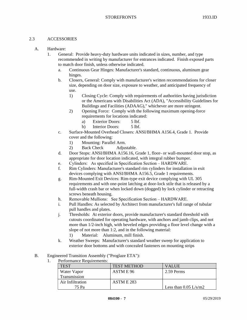
STOREFRONTS 1933.ID
2.3 ACCESSORIES
A. Hardware:1. General: Provide heavy-duty hardware units indicated in sizes, number, and type
recommended in writing by manufacturer for entrances indicated. Finish exposed parts to match door finish, unless otherwise indicated.a. Continuous Gear Hinges: Manufacturer's standard, continuous, aluminum gear
hinges.b. Closers, General: Comply with manufacturer's written recommendations for closer
size, depending on door size, exposure to weather, and anticipated frequency of use.1) Closing Cycle: Comply with requirements of authorities having jurisdiction
or the Americans with Disabilities Act (ADA), "Accessibility Guidelines for Buildings and Facilities (ADAAG)," whichever are more stringent.
2) Opening Force: Comply with the following maximum opening-force requirements for locations indicated:a) Exterior Doors: 5 lbf.b) Interior Doors: 5 lbf.
c. Surface-Mounted Overhead Closers: ANSI/BHMA A156.4, Grade 1. Provide cover and the following:1) Mounting: Parallel Arm.2) Back Check Adjustable.
d. Door Stops: ANSI/BHMA A156.16, Grade 1, floor- or wall-mounted door stop, as appropriate for door location indicated, with integral rubber bumper.
e. Cylinders: As specified in Specification Section – HARDWARE.f. Rim Cylinders: Manufacturer's standard rim cylinders for installation in exit
devices complying with ANSI/BHMA A156.5, Grade 1 requirements.g. Rim-Mounted Exit Devices: Rim-type exit device complying with UL 305
requirements and with one-point latching at door-lock stile that is released by a full-width crash bar or when locked down (dogged) by lock cylinder or retracting screws beneath housing.
h. Removable Mullions: See Specification Section – HARDWARE.i. Pull Handles: As selected by Architect from manufacturer's full range of tubular
pull handles and plates.j. Thresholds: At exterior doors, provide manufacturer's standard threshold with
cutouts coordinated for operating hardware, with anchors and jamb clips, and not more than 1/2-inch high, with beveled edges providing a floor level change with a slope of not more than 1:2, and in the following material:1) Material: Aluminum, mill finish.
k. Weather Sweeps: Manufacturer's standard weather sweep for application to exterior door bottoms and with concealed fasteners on mounting strips
B. Engineered Transition Assembly ("Proglaze ETA"):1. Performance Requirements:
TEST TEST METHOD VALUEWater Vapor Transmission
ASTM E 96 2.59 Perms
Air Infiltration75 Pa
ASTM E 283Less than 0.05 L/s/m2
084100 - 7 05/29/2019
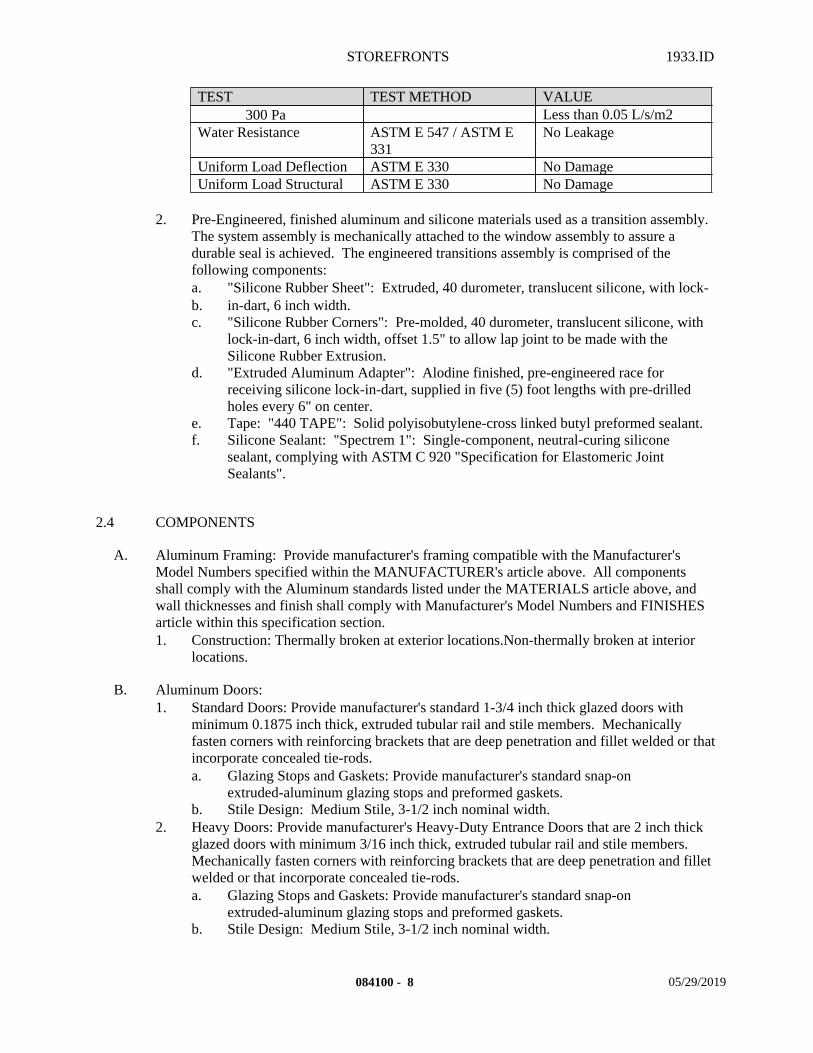
STOREFRONTS 1933.ID
TEST TEST METHOD VALUE300 Pa Less than 0.05 L/s/m2
Water Resistance ASTM E 547 / ASTM E 331
No Leakage
Uniform Load Deflection ASTM E 330 No DamageUniform Load Structural ASTM E 330 No Damage
2. Pre-Engineered, finished aluminum and silicone materials used as a transition assembly.
The system assembly is mechanically attached to the window assembly to assure a durable seal is achieved. The engineered transitions assembly is comprised of the following components: a. "Silicone Rubber Sheet": Extruded, 40 durometer, translucent silicone, with lock-b. in-dart, 6 inch width.c. "Silicone Rubber Corners": Pre-molded, 40 durometer, translucent silicone, with
lock-in-dart, 6 inch width, offset 1.5" to allow lap joint to be made with the Silicone Rubber Extrusion.
d. "Extruded Aluminum Adapter": Alodine finished, pre-engineered race for receiving silicone lock-in-dart, supplied in five (5) foot lengths with pre-drilled holes every 6" on center.
e. Tape: "440 TAPE": Solid polyisobutylene-cross linked butyl preformed sealant.f. Silicone Sealant: "Spectrem 1": Single-component, neutral-curing silicone
sealant, complying with ASTM C 920 "Specification for Elastomeric Joint Sealants".
2.4 COMPONENTS
A. Aluminum Framing: Provide manufacturer's framing compatible with the Manufacturer's Model Numbers specified within the MANUFACTURER's article above. All components shall comply with the Aluminum standards listed under the MATERIALS article above, and wall thicknesses and finish shall comply with Manufacturer's Model Numbers and FINISHES article within this specification section.1. Construction: Thermally broken at exterior locations.Non-thermally broken at interior
locations.
B. Aluminum Doors:1. Standard Doors: Provide manufacturer's standard 1-3/4 inch thick glazed doors with
minimum 0.1875 inch thick, extruded tubular rail and stile members. Mechanically fasten corners with reinforcing brackets that are deep penetration and fillet welded or that incorporate concealed tie-rods.a. Glazing Stops and Gaskets: Provide manufacturer's standard snap-on
extruded-aluminum glazing stops and preformed gaskets.b. Stile Design: Medium Stile, 3-1/2 inch nominal width.
2. Heavy Doors: Provide manufacturer's Heavy-Duty Entrance Doors that are 2 inch thick glazed doors with minimum 3/16 inch thick, extruded tubular rail and stile members. Mechanically fasten corners with reinforcing brackets that are deep penetration and fillet welded or that incorporate concealed tie-rods.a. Glazing Stops and Gaskets: Provide manufacturer's standard snap-on
extruded-aluminum glazing stops and preformed gaskets.b. Stile Design: Medium Stile, 3-1/2 inch nominal width.
084100 - 8 05/29/2019
STOREFRONTS 1933.ID
C. Brackets and Reinforcements: Provide manufacturer's standard brackets and reinforcements that are compatible with adjacent materials. Provide non-staining, nonferrous shims for aligning system components.
D. Fasteners and Accessories: Manufacturer's standard corrosion-resistant, non-staining, non-bleeding, flashing, compatible with adjacent materials, and of type recommended in writing by manufacturer.
E. Weatherstripping: Manufacturer's standard replaceable weatherstripping as follows:1. Compression Weatherstripping: Molded neoprene complying with ASTM D 2000
"Classification System for Rubber Products in Automotive Applications" requirements or molded PVC complying with ASTM D 2287 "Specification for Nonrigid Vinyl Chloride Polymer and Copolymer Molding and Extrusion Compounds" requirements.
2.5 FABRICATION
A. General: Fabricate components that, when assembled, will have accurately fitted joints with ends coped or mitered to produce hairline joints free of burrs and distortion. After fabrication, clearly mark components to identify their locations in Project according to Shop Drawings.1. Fabricate storefront system components for screw-spline frame construction.2. Fabricate window wall system and entrance door components for shear-block frame
construction.3. Fabricate components for head- and sill-receptor frame construction with shear-block
construction at intermediate horizontal components.
B. Forming: Form shapes with sharp profiles, straight and free of defects or deformations, before finishing.
C. Prepare components to receive concealed fasteners and anchor and connection devices.
D. Fabricate components to drain water passing joints and condensation and moisture occurring or migrating within the system to the exterior.
E. Welding: Weld components to comply with referenced AWS standard. Weld before finishing components to greatest extent possible. Weld in concealed locations to greatest extent possible to minimize distortion or discoloration of finish. Remove weld spatter and welding oxides from exposed surfaces by descaling or grinding.
F. Glazing Channels: Provide minimum clearances for thickness and type of glass indicated according to GANA's "Glazing Manual."
G. Glazing Channels: Provide minimum clearances for thickness and type of plastic sheet indicated according to plastic sheet manufacturer's written instructions.
H. Metal Protection: Where aluminum will contact dissimilar metals, protect against galvanic action by painting contact surfaces with primer or by applying sealant or tape recommended in writing by manufacturer for this purpose. Where aluminum will contact concrete or masonry, protect against corrosion by painting contact surfaces with bituminous paint.
084100 - 9 05/29/2019
STOREFRONTS 1933.ID
I. Storefront: Fabricate framing in profiles indicated for flush glazing (without projecting stops). Provide subframes and reinforcing of types indicated or, if not indicated, as required for a complete system. Factory assemble components to greatest extent possible. Disassemble components only as necessary for shipment and installation.
J. Entrances: Fabricate door framing in profiles indicated. Reinforce as required to support imposed loads. Factory assemble door and frame units and factory install hardware to greatest extent possible. Reinforce door and frame units as required for installing hardware indicated. Cut, drill, and tap for factory-installed hardware before finishing components.1. Exterior Doors: Provide compression weather stripping at fixed stops.2. Interior Doors: Provide ANSI/BHMA A156.16 silencers at stops to prevent metal to
metal contact. Provide 3 silencers on strike jamb of single-door frames and 2 silencers on head of double-door frames.
2.6 FINISHES
A. Aluminum:1. General: Comply with NAAMM's "Metal Finishes Manual for Architectural and Metal
Products" for recommendations relative to applying and designating finishes.2. Appearance of Finished Work: Variations in appearance of abutting or adjacent pieces
are acceptable if they are within one-half of the range of approved Samples. Noticeable variations in the same piece are not acceptable. Variations in appearance of other components are acceptable if they are within the range of approved Samples and are assembled or installed to minimize contrast.
3. Finish designations prefixed by AA conform to the system established by the Aluminum Association for designating aluminum finishes.
4. Color Anodic Finish: AAMA 611, AA-M12C22A42/A44, Class I, 0.018 mm or thicker.a. Color: Match to Adjacent Existing Storefront..
B. Steel Priming:1. General: Comply with NAAMM's "Metal Finishes Manual for Architectural and Metal
Products" for recommendations relative to applying primer.2. Surface Preparation: Perform manufacturer's standard cleaning operations to remove dirt,
oil, grease, or other contaminants that could impair paint bond. Remove mill scale and rust, if present, from uncoated steel.
3. Priming: Apply manufacturer's standard corrosion-resistant primer immediately after surface preparation and pretreatment.
2.7 SOURCE QUALITY CONTROL
A. Tests, Inspection:1. Pre-Construction Sealant Testing: Perform sealant manufacturer's standard tests for
compatibility and adhesion of sealants with each material that will come in contact with sealants and each condition required by system.a. Test a minimum of 8 samples of each metal, glazing, and other material.b. Prepare samples using techniques and primers required for installed systems.c. Perform tests under environmental conditions that duplicate those under which
systems will be installed.
084100 - 10 05/29/2019
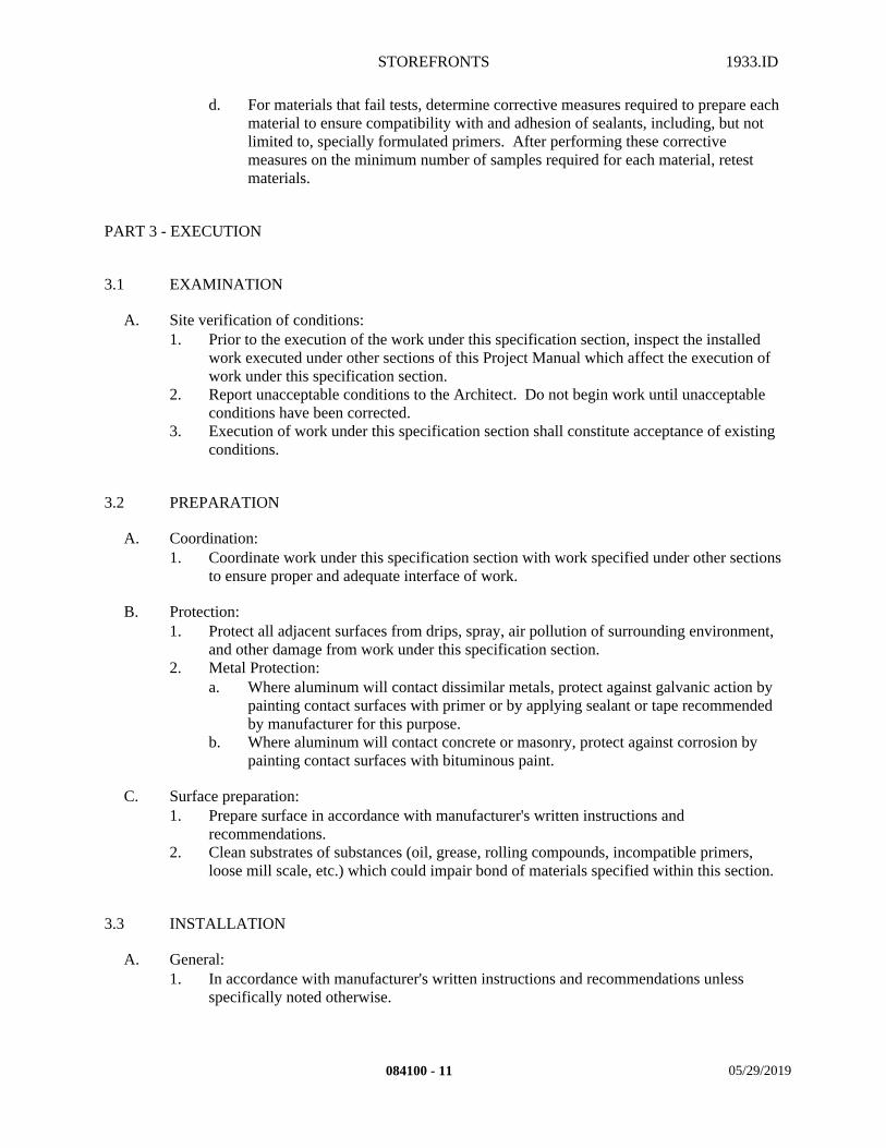
STOREFRONTS 1933.ID
d. For materials that fail tests, determine corrective measures required to prepare each material to ensure compatibility with and adhesion of sealants, including, but not limited to, specially formulated primers. After performing these corrective measures on the minimum number of samples required for each material, retest materials.
PART 3 - EXECUTION
3.1 EXAMINATION
A. Site verification of conditions:1. Prior to the execution of the work under this specification section, inspect the installed
work executed under other sections of this Project Manual which affect the execution of work under this specification section.
2. Report unacceptable conditions to the Architect. Do not begin work until unacceptable conditions have been corrected.
3. Execution of work under this specification section shall constitute acceptance of existing conditions.
3.2 PREPARATION
A. Coordination:1. Coordinate work under this specification section with work specified under other sections
to ensure proper and adequate interface of work.
B. Protection:1. Protect all adjacent surfaces from drips, spray, air pollution of surrounding environment,
and other damage from work under this specification section.2. Metal Protection:
a. Where aluminum will contact dissimilar metals, protect against galvanic action by painting contact surfaces with primer or by applying sealant or tape recommended by manufacturer for this purpose.
b. Where aluminum will contact concrete or masonry, protect against corrosion by painting contact surfaces with bituminous paint.
C. Surface preparation:1. Prepare surface in accordance with manufacturer's written instructions and
recommendations.2. Clean substrates of substances (oil, grease, rolling compounds, incompatible primers,
loose mill scale, etc.) which could impair bond of materials specified within this section.
3.3 INSTALLATION
A. General:1. In accordance with manufacturer's written instructions and recommendations unless
specifically noted otherwise.
084100 - 11 05/29/2019

STOREFRONTS 1933.ID
a. Comply with manufacturer's written instructions for protecting, handling, and installing entrance and storefront systems.
2. In accordance with approved submittals.3. In accordance with Regulatory Requirements.4. Set plumb, level, and square.5. Do not install damaged components.6. Fit frame joints to produce hairline joints free of burrs and distortion.7. Rigidly secure non-movement joints.8. Install components to drain water passing joints and condensation and moisture occurring
or migrating within the system to the exterior.9. Set continuous sill members and flashing in a full sealant bed to provide weathertight
construction, unless otherwise indicated.10. Install Silicone Engineered Transitions in accordance with manufacturer's written
instructions. 11. Seal joints weathertight.
B. Layout:1. Lines shall be straight and true.
a. Install framing components plumb and true in alignment with established lines and grades without warp or rack of framing members.
b. Install entrances plumb and true in alignment with established lines and grades without warp or rack. Lubricate operating hardware and other moving parts according to hardware manufacturers' written instructions.1) Install surface-mounted hardware according to manufacturer's written
instructions using concealed fasteners to greatest extent possible.c. Install glazing as follows:
1) Prepare surfaces that will contact structural sealant according to sealant manufacturer's written instructions to ensure compatibility and adhesion. a) Preparation includes, but is not limited to, cleaning and priming
surfaces.2) Install structural silicone sealant according to sealant manufacturer's written
instructions.3) Mechanically fasten glazing in place until structural sealant is cured.4) Remove excess sealant from component surfaces before sealant has cured.5) Install sealant weatherseal according to sealant manufacturer's written
instructions to provide weatherproof joints. a) Install joint fillers behind sealant as recommended in writing by
sealant manufacturer.6) Install perimeter sealant to comply with requirements of Specification
Section - SEALANTS unless otherwise indicated.
C. Assistance:1. Application shall be in direct consultation and review of manufacturer's representative.
3.4 FIELD QUALITY CONTROL
A. Installation Tolerances:1. Install aluminum systems to comply with the following maximum tolerances:
a. Variation from Plane: Limit variation from plane or location shown to 1/8 inch in 12 feet; 1/4 inch over total length.
084100 - 12 05/29/2019
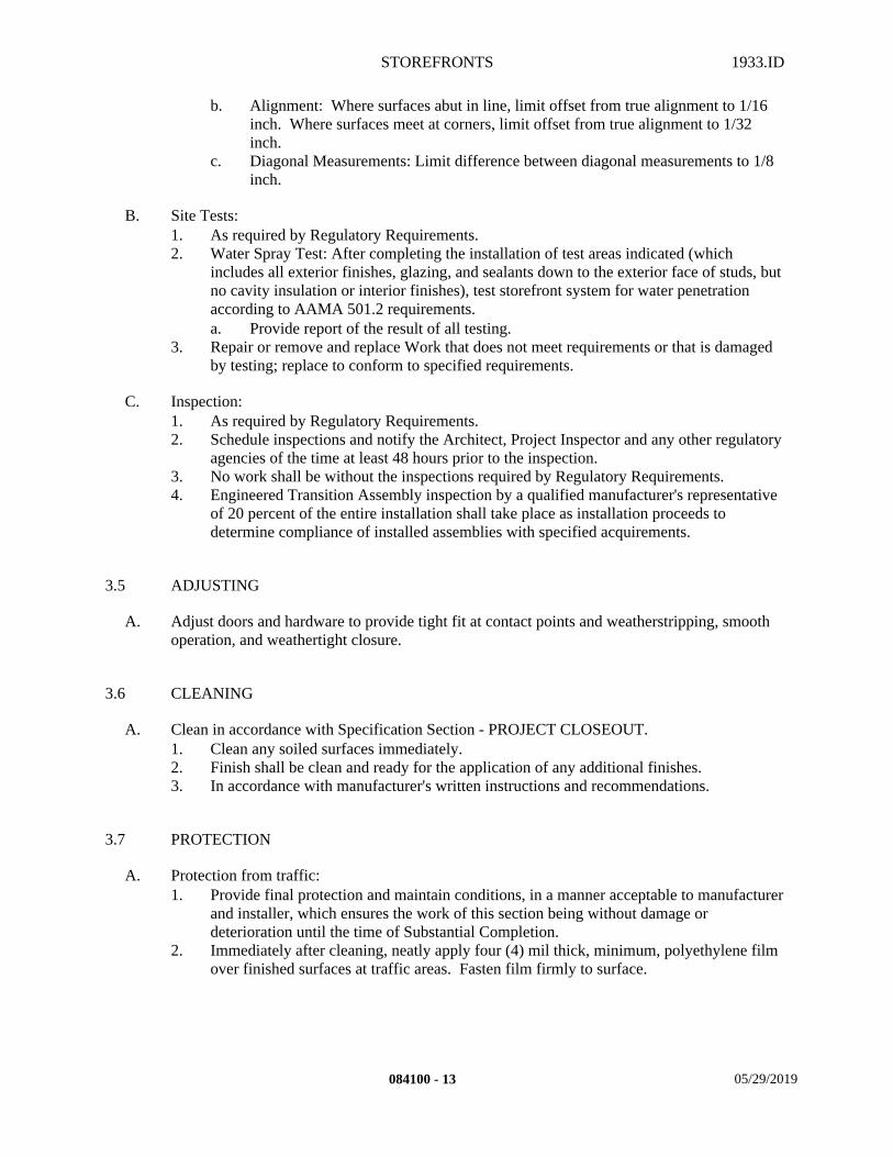
STOREFRONTS 1933.ID
b. Alignment: Where surfaces abut in line, limit offset from true alignment to 1/16 inch. Where surfaces meet at corners, limit offset from true alignment to 1/32 inch.
c. Diagonal Measurements: Limit difference between diagonal measurements to 1/8 inch.
B. Site Tests:1. As required by Regulatory Requirements.2. Water Spray Test: After completing the installation of test areas indicated (which
includes all exterior finishes, glazing, and sealants down to the exterior face of studs, but no cavity insulation or interior finishes), test storefront system for water penetration according to AAMA 501.2 requirements.a. Provide report of the result of all testing.
3. Repair or remove and replace Work that does not meet requirements or that is damaged by testing; replace to conform to specified requirements.
C. Inspection:1. As required by Regulatory Requirements.2. Schedule inspections and notify the Architect, Project Inspector and any other regulatory
agencies of the time at least 48 hours prior to the inspection.3. No work shall be without the inspections required by Regulatory Requirements.4. Engineered Transition Assembly inspection by a qualified manufacturer's representative
of 20 percent of the entire installation shall take place as installation proceeds to determine compliance of installed assemblies with specified acquirements.
3.5 ADJUSTING
A. Adjust doors and hardware to provide tight fit at contact points and weatherstripping, smooth operation, and weathertight closure.
3.6 CLEANING
A. Clean in accordance with Specification Section - PROJECT CLOSEOUT.1. Clean any soiled surfaces immediately.2. Finish shall be clean and ready for the application of any additional finishes.3. In accordance with manufacturer's written instructions and recommendations.
3.7 PROTECTION
A. Protection from traffic: 1. Provide final protection and maintain conditions, in a manner acceptable to manufacturer
and installer, which ensures the work of this section being without damage or deterioration until the time of Substantial Completion.
2. Immediately after cleaning, neatly apply four (4) mil thick, minimum, polyethylene film over finished surfaces at traffic areas. Fasten film firmly to surface.
084100 - 13 05/29/2019
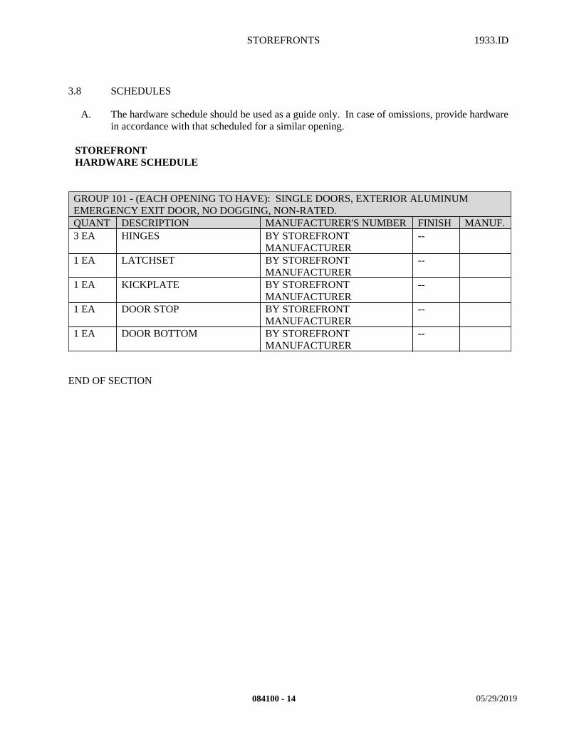
STOREFRONTS 1933.ID
3.8 SCHEDULES
A. The hardware schedule should be used as a guide only. In case of omissions, provide hardware in accordance with that scheduled for a similar opening.
STOREFRONTHARDWARE SCHEDULE
GROUP 101 - (EACH OPENING TO HAVE): SINGLE DOORS, EXTERIOR ALUMINUM EMERGENCY EXIT DOOR, NO DOGGING, NON-RATED.QUANT DESCRIPTION MANUFACTURER'S NUMBER FINISH MANUF.3 EA HINGES BY STOREFRONT
MANUFACTURER--
1 EA LATCHSET BY STOREFRONT MANUFACTURER
--
1 EA KICKPLATE BY STOREFRONT MANUFACTURER
--
1 EA DOOR STOP BY STOREFRONT MANUFACTURER
--
1 EA DOOR BOTTOM BY STOREFRONT MANUFACTURER
--
END OF SECTION
084100 - 14 05/29/2019
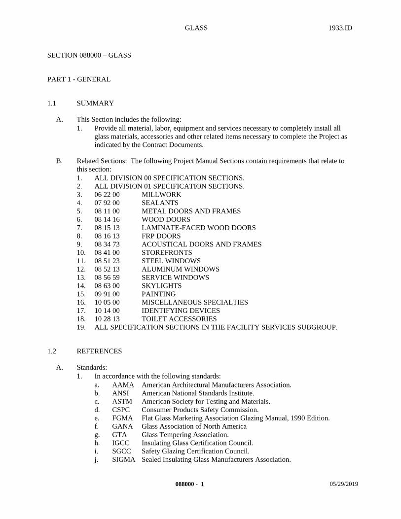
GLASS 1933.ID
SECTION 088000 – GLASS
PART 1 - GENERAL
1.1 SUMMARY
A. This Section includes the following:1. Provide all material, labor, equipment and services necessary to completely install all
glass materials, accessories and other related items necessary to complete the Project as indicated by the Contract Documents.
B. Related Sections: The following Project Manual Sections contain requirements that relate to this section:1. ALL DIVISION 00 SPECIFICATION SECTIONS.2. ALL DIVISION 01 SPECIFICATION SECTIONS.3. 06 22 00 MILLWORK4. 07 92 00 SEALANTS5. 08 11 00 METAL DOORS AND FRAMES6. 08 14 16 WOOD DOORS7. 08 15 13 LAMINATE-FACED WOOD DOORS8. 08 16 13 FRP DOORS9. 08 34 73 ACOUSTICAL DOORS AND FRAMES10. 08 41 00 STOREFRONTS11. 08 51 23 STEEL WINDOWS12. 08 52 13 ALUMINUM WINDOWS13. 08 56 59 SERVICE WINDOWS14. 08 63 00 SKYLIGHTS15. 09 91 00 PAINTING16. 10 05 00 MISCELLANEOUS SPECIALTIES17. 10 14 00 IDENTIFYING DEVICES18. 10 28 13 TOILET ACCESSORIES19. ALL SPECIFICATION SECTIONS IN THE FACILITY SERVICES SUBGROUP.
1.2 REFERENCES
A. Standards:1. In accordance with the following standards:
a. AAMA American Architectural Manufacturers Association.b. ANSI American National Standards Institute.c. ASTM American Society for Testing and Materials.d. CSPC Consumer Products Safety Commission.e. FGMA Flat Glass Marketing Association Glazing Manual, 1990 Edition.f. GANA Glass Association of North Americag. GTA Glass Tempering Association.h. IGCC Insulating Glass Certification Council.i. SGCC Safety Glazing Certification Council.j. SIGMA Sealed Insulating Glass Manufacturers Association.
088000 - 1 05/29/2019
GLASS 1933.ID
1.3 DEFINITIONS
A. Manufacturer is used in this Section to refer to a firm that produces primary glazing, fabricated glazing, or both as defined in the referenced glazing standards.1. Deterioration of Coated Glass: Defects developed from normal use that are attributed to
the manufacturing process and not to causes other than glass breakage and practices for maintaining and cleaning coated glass contrary to manufacturer's written directions. Defects include peeling, cracking, and other indications of deterioration in metallic coating.
2. Deterioration of Laminated Glass: Defects developed from normal use that are attributed to the manufacturing process and not to glass breakage and practices for maintaining and cleaning laminated glass contrary to manufacturer's written directions. Defects include edge separation, delamination materially obstructing vision through glass, and blemishes exceeding those allowed by referenced laminated glass standard.
3. Deterioration of Insulating Glass: Failure of the hermetic seal under normal use that is attributed the manufacturing process and not to causes other than glass breakage and improper practices for maintaining, and cleaning insulating glass contrary to manufacturers written instructions. Evidence of failure is the obstruction of vision by dust, moisture, or film on the interior surfaces of glass.
4. f.o.b. – "Free On Board".5. Glass Surfaces:
a. Single Glazed:1) Surface #1: exposed to outdoors.2) Surface #2: exposed to indoors.
b. Dual Glazed:1) Exterior Lite:
a) Surface #1: exposed to outdoors. b) Surface #2: faces insulating "air" space. Primary location for energy
efficient coatings. 2) Interior Lite:
a) Surface #3: faces insulating "air" space. Secondary location for energy efficient coatings.
b) Surface #4: exposed to indoors.
1.4 SYSTEM DESCRIPTION
A. Performance Requirements: It is the intention of this specification and the drawings to form a guide for a completely sealed glazing system. Any items not specifically noted but necessary for a completely sealed glazing system shall be provided under this section.1. Provide glazing systems that are produced, fabricated, and installed to withstand normal
thermal movement, wind loading, and impact loading (where applicable), without failure, including loss or glazing breakage attributable to the following: defective manufacture, fabrication, and installation; failure of sealants or gaskets to remain watertight and airtight; deterioration of glazing materials; and other defects in construction.
2. Glass Design: Glass thickness indicate minimums and are for detailing only. Confirm glass thicknesses by analyzing Project loads and in-service conditions. Provide glass lites for the various size openings in the thicknesses and strengths (annealed or heat-treated) to meet or exceed the following criteria:
088000 - 2 05/29/2019
GLASS 1933.ID
a. Minimum glass thickness for lites in exterior walls shall be not less than 6.0mm (1/4" nom.).
3. Thermal Movement: Provide glazing that allows for thermal movement resulting from the following maximum change (range) in ambient and surface temperatures acting on glass-framing members and glazing components. Base engineering calculation on material's actual surface temperatures due to both solar heat gain and nighttime sky heat loss.a. Temperature Change Range: 120 deg F, ambient; 180 deg F, material surfaces..
1.5 SUBMITTALS
A. Submit in accordance with Specification Section - SUBMITTAL PROCEDURES:1. Coordination Drawings:
a. Submit installer's coordination drawings indicating the work of this section with that of related work of other sections for proper interface of the completed work. Installer shall coordinate and obtain approvals from the work of other related sections prior to submitting to the Architect.
2. Product Data.a. Submit manufacturer's product data for each glazing product and accessory
material indicated.3. Samples.
a. Provide 12 inch square sample of each glass type, color and pattern selected.b. Provide 6 inch square samples of insulated glazing panels for each glazing type and
pattern selected.c. Provide 12 inch long samples of each type of glazing sealant, gasket or glazing
tape. Install sealant or glazing material sample between two strips of material representative in color of the adjoining framing system.
4. Quality Assurance/Control Submittals:a. Test Reports:
1) Compatibility and Adhesion Test: From sealant manufacturer indicating that glazing sealants were tested for adhesion to glass and glazing channel substrates and compatibility with glass and other glazing material.
b. Certificates:1) Contractor's Certification.2) Qualification Data:
a) Material Qualifications.b) Installer Qualifications.c) Manufacturer/Supplier Qualifications.
c. Manufacturer's Written Instructions:1) Manufacturer's written installation instructions for all products.
5. Closeout Submittals in accordance with the following:a. Maintenance Data in accordance with Specification Section - PROJECT
CLOSEOUT.b. Record Documents in accordance with Specification Section - RECORD
DOCUMENTS.c. Warranty in accordance with Specification Section - WARRANTIES.
1) Special Warranties: a) Coated Glass Products.b) Insulated Glass Products.
088000 - 3 05/29/2019
GLASS 1933.ID
1.6 QUALITY ASSURANCE
A. Qualifications:1. Material Qualifications:
a. Comply with published recommendations of glazing product manufacturers and organizations listed, except where more stringent requirements are indicated. Refer to these publications for glazing terms not otherwise defined in this Section or in referenced standards.
b. Obtain glazing from one source for each product indicated.2. Installer Qualifications:
a. An experienced Installer who has completed three (3) projects similar in materials, design and extent to that indicated for this Project; whose work has resulted in glass installation with a record of successful in-service performance..
3. Manufacturer/Supplier Qualifications:a. Firm experienced in successfully producing/supplying products similar to that
indicated for this Project, with sufficient production/supply capacity to produce/supply required units without causing delay in the work.
B. Regulatory Requirements:1. In accordance with Specification Section - REGULATORY REQUIREMENTS, and the
following:a. CARB Materials and equipment used for this Project shall comply with the
current applicable regulations of the California Air Resources Board (CARB) and the Environmental Protection Agency (EPA), in the area where the project is located.
b. All glazing shall comply with provisions of CBC Chapter 24 for quality standards and CBC Section 2403.1 for identification.
c. All glazing subject to Hazardous Locations shall comply with Safety Glazing Requirements and CBC Chapter 2406.
C. Certificates:1. Contractor's Certification: Provide a letter on Contractor's Letterhead certifying work
provided, meets or exceeds, the Code Minimum requirements, and the other specified requirements of this Section.
2. Qualification Data: Contractor's installation certificates.3. Product Certificates: Glazing materials manufacturers certifying that their products
comply with specified requirements.
D. Meetings:1. Pre-Installation:Schedule prior to the start of work.
a. Coordinate the work with other work being performed.b. Identify any potential problems that may impede planned progress and proper
installation of work regarding quality of installation and warranty requirements. c. Pre-glazing conference: Scheduled by the Contractor prior to the start of any
glazing operation for the proper performance of the work.1) Minimum agenda shall be to review the work required; discuss field
observations, problems, and decisions; corrective measures if necessary; and maintenance of quality and work standards in accordance with manufacturer's warranty requirements.
088000 - 4 05/29/2019
GLASS 1933.ID
2. Progress: Scheduled by the Contractor during the performance of the work.a. Review for proper installation of work progress.b. Identify any installation problems and acceptable corrective measures.c. Identify any measures to maintain or regain project schedule if necessary.
3. Completion: Scheduled by the Contractor upon proper completion of the work.a. Inspect and identify any problems that may impede issuance of warranties or
guaranties.b. Maintaining installed work until the Notice of Substantial Completion has been
executed.
1.7 DELIVERY, STORAGE, AND HANDLING
A. Packing, shipping, handling, and unloading: 1. Products shall be handled in such a manner as to assure that they are free from dents,
scratches and other damage.a. Protect glazing materials to comply with manufacturer's written directions and as
needed to prevent damage to glazing and glazing materials from condensation, temperature changes, direct exposure to sun, or other causes.
2. Where insulating glass units will be exposed to substantial altitude changes, comply with insulating glass fabricator's recommendations for venting and sealing to avoid hermetic seal ruptures.
B. Acceptance at Site: 1. Products must be in manufacturer's original unopened containers with labels indicating
brand name, model, and grade. 2. Damaged products will not be accepted.
C. Storage and Protection: 1. Products shall be stored above ground on level platforms, six (6) inches above ground,
allowing air circulation under stacked units. a. Cover materials with protective waterproof covering providing for adequate air
circulation and ventilation.
1.8 PROJECT CONDITIONS
A. Environmental Requirements:1. Do not proceed with glazing when ambient and substrate temperature conditions are
outside the limits permitted by glazing materials manufacturer or when glazing channel substrates are wet from rain, frost, condensation, or other causes.a. Do not install liquid sealants when ambient and substrate temperature conditions
are outside of limits by glazing sealant manufacturer or below 40 deg F.
1.9 WARRANTY
A. Contractor's General Warranty:1. In accordance with Specification Section - WARRANTIES.
B. Manufacturer’s Warranty:
088000 - 5 05/29/2019
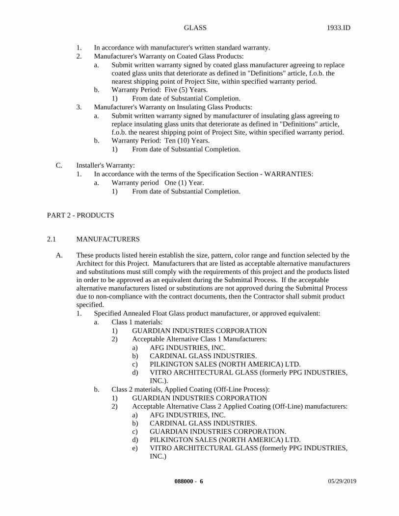
GLASS 1933.ID
1. In accordance with manufacturer's written standard warranty.2. Manufacturer's Warranty on Coated Glass Products:
a. Submit written warranty signed by coated glass manufacturer agreeing to replace coated glass units that deteriorate as defined in "Definitions" article, f.o.b. the nearest shipping point of Project Site, within specified warranty period.
b. Warranty Period: Five (5) Years.1) From date of Substantial Completion.
3. Manufacturer's Warranty on Insulating Glass Products:a. Submit written warranty signed by manufacturer of insulating glass agreeing to
replace insulating glass units that deteriorate as defined in "Definitions" article, f.o.b. the nearest shipping point of Project Site, within specified warranty period.
b. Warranty Period: Ten (10) Years.1) From date of Substantial Completion.
C. Installer's Warranty:1. In accordance with the terms of the Specification Section - WARRANTIES:
a. Warranty period One (1) Year.1) From date of Substantial Completion.
PART 2 - PRODUCTS
2.1 MANUFACTURERS
A. These products listed herein establish the size, pattern, color range and function selected by the Architect for this Project. Manufacturers that are listed as acceptable alternative manufacturers and substitutions must still comply with the requirements of this project and the products listed in order to be approved as an equivalent during the Submittal Process. If the acceptable alternative manufacturers listed or substitutions are not approved during the Submittal Process due to non-compliance with the contract documents, then the Contractor shall submit product specified. 1. Specified Annealed Float Glass product manufacturer, or approved equivalent:
a. Class 1 materials:1) GUARDIAN INDUSTRIES CORPORATION2) Acceptable Alternative Class 1 Manufacturers:
a) AFG INDUSTRIES, INC.b) CARDINAL GLASS INDUSTRIES.c) PILKINGTON SALES (NORTH AMERICA) LTD.d) VITRO ARCHITECTURAL GLASS (formerly PPG INDUSTRIES,
INC.).b. Class 2 materials, Applied Coating (Off-Line Process):
1) GUARDIAN INDUSTRIES CORPORATION2) Acceptable Alternative Class 2 Applied Coating (Off-Line) manufacturers:
a) AFG INDUSTRIES, INC.b) CARDINAL GLASS INDUSTRIES.c) GUARDIAN INDUSTRIES CORPORATION.d) PILKINGTON SALES (NORTH AMERICA) LTD.e) VITRO ARCHITECTURAL GLASS (formerly PPG INDUSTRIES,
INC.)
088000 - 6 05/29/2019
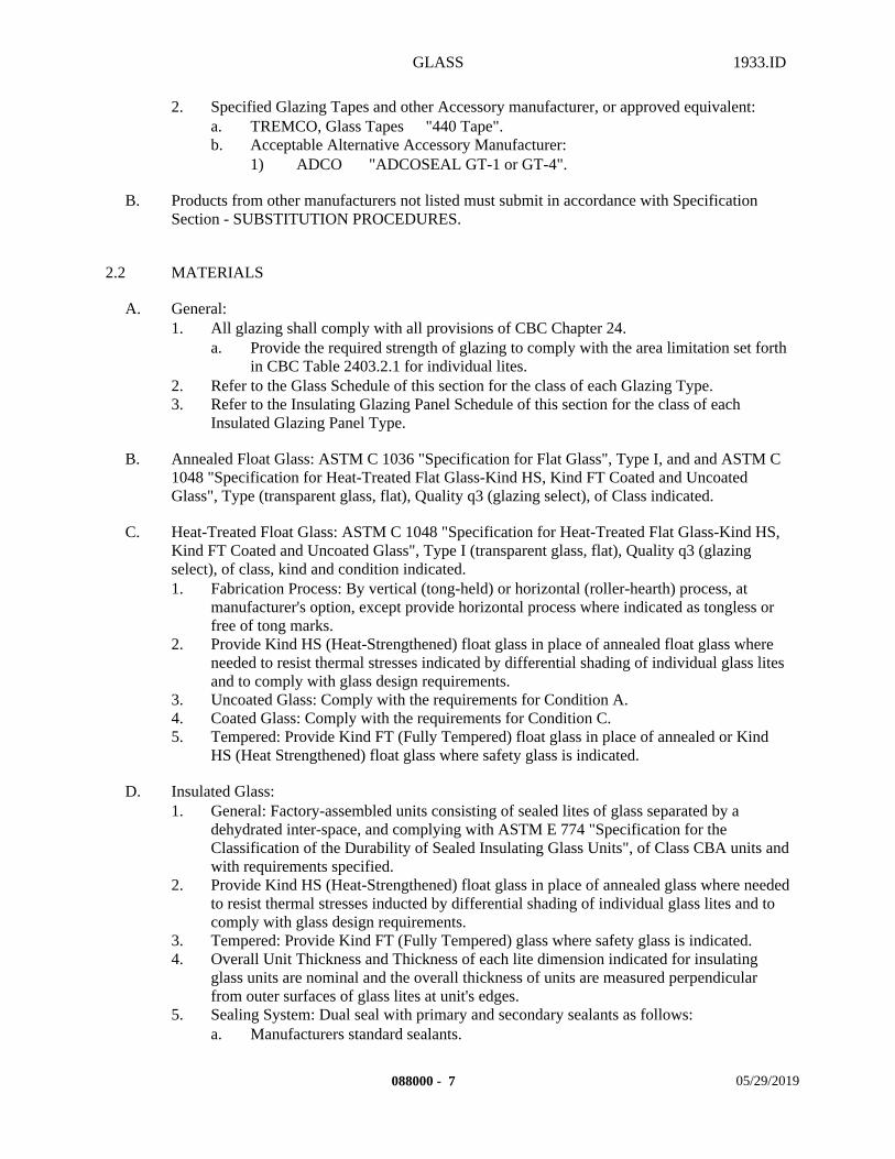
GLASS 1933.ID
2. Specified Glazing Tapes and other Accessory manufacturer, or approved equivalent:a. TREMCO, Glass Tapes "440 Tape".b. Acceptable Alternative Accessory Manufacturer:
1) ADCO "ADCOSEAL GT-1 or GT-4".
B. Products from other manufacturers not listed must submit in accordance with Specification Section - SUBSTITUTION PROCEDURES.
2.2 MATERIALS
A. General:1. All glazing shall comply with all provisions of CBC Chapter 24.
a. Provide the required strength of glazing to comply with the area limitation set forth in CBC Table 2403.2.1 for individual lites.
2. Refer to the Glass Schedule of this section for the class of each Glazing Type.3. Refer to the Insulating Glazing Panel Schedule of this section for the class of each
Insulated Glazing Panel Type.
B. Annealed Float Glass: ASTM C 1036 "Specification for Flat Glass", Type I, and and ASTM C 1048 "Specification for Heat-Treated Flat Glass-Kind HS, Kind FT Coated and Uncoated Glass", Type (transparent glass, flat), Quality q3 (glazing select), of Class indicated.
C. Heat-Treated Float Glass: ASTM C 1048 "Specification for Heat-Treated Flat Glass-Kind HS, Kind FT Coated and Uncoated Glass", Type I (transparent glass, flat), Quality q3 (glazing select), of class, kind and condition indicated.1. Fabrication Process: By vertical (tong-held) or horizontal (roller-hearth) process, at
manufacturer's option, except provide horizontal process where indicated as tongless or free of tong marks.
2. Provide Kind HS (Heat-Strengthened) float glass in place of annealed float glass where needed to resist thermal stresses indicated by differential shading of individual glass lites and to comply with glass design requirements.
3. Uncoated Glass: Comply with the requirements for Condition A.4. Coated Glass: Comply with the requirements for Condition C.5. Tempered: Provide Kind FT (Fully Tempered) float glass in place of annealed or Kind
HS (Heat Strengthened) float glass where safety glass is indicated.
D. Insulated Glass:1. General: Factory-assembled units consisting of sealed lites of glass separated by a
dehydrated inter-space, and complying with ASTM E 774 "Specification for the Classification of the Durability of Sealed Insulating Glass Units", of Class CBA units and with requirements specified.
2. Provide Kind HS (Heat-Strengthened) float glass in place of annealed glass where needed to resist thermal stresses inducted by differential shading of individual glass lites and to comply with glass design requirements.
3. Tempered: Provide Kind FT (Fully Tempered) glass where safety glass is indicated.4. Overall Unit Thickness and Thickness of each lite dimension indicated for insulating
glass units are nominal and the overall thickness of units are measured perpendicular from outer surfaces of glass lites at unit's edges.
5. Sealing System: Dual seal with primary and secondary sealants as follows:a. Manufacturers standard sealants.
088000 - 7 05/29/2019
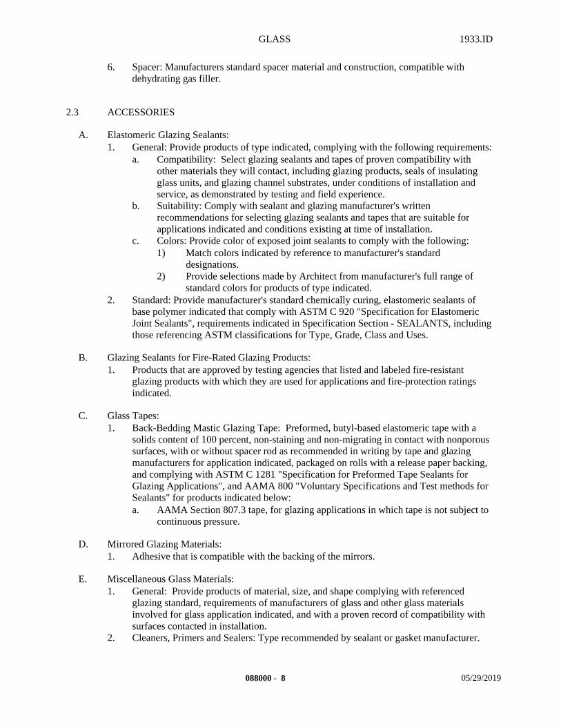
GLASS 1933.ID
6. Spacer: Manufacturers standard spacer material and construction, compatible with dehydrating gas filler.
2.3 ACCESSORIES
A. Elastomeric Glazing Sealants:1. General: Provide products of type indicated, complying with the following requirements:
a. Compatibility: Select glazing sealants and tapes of proven compatibility with other materials they will contact, including glazing products, seals of insulating glass units, and glazing channel substrates, under conditions of installation and service, as demonstrated by testing and field experience.
b. Suitability: Comply with sealant and glazing manufacturer's written recommendations for selecting glazing sealants and tapes that are suitable for applications indicated and conditions existing at time of installation.
c. Colors: Provide color of exposed joint sealants to comply with the following:1) Match colors indicated by reference to manufacturer's standard
designations.2) Provide selections made by Architect from manufacturer's full range of
standard colors for products of type indicated.2. Standard: Provide manufacturer's standard chemically curing, elastomeric sealants of
base polymer indicated that comply with ASTM C 920 "Specification for Elastomeric Joint Sealants", requirements indicated in Specification Section - SEALANTS, including those referencing ASTM classifications for Type, Grade, Class and Uses.
B. Glazing Sealants for Fire-Rated Glazing Products:1. Products that are approved by testing agencies that listed and labeled fire-resistant
glazing products with which they are used for applications and fire-protection ratings indicated.
C. Glass Tapes:1. Back-Bedding Mastic Glazing Tape: Preformed, butyl-based elastomeric tape with a
solids content of 100 percent, non-staining and non-migrating in contact with nonporous surfaces, with or without spacer rod as recommended in writing by tape and glazing manufacturers for application indicated, packaged on rolls with a release paper backing, and complying with ASTM C 1281 "Specification for Preformed Tape Sealants for Glazing Applications", and AAMA 800 "Voluntary Specifications and Test methods for Sealants" for products indicated below: a. AAMA Section 807.3 tape, for glazing applications in which tape is not subject to
continuous pressure.
D. Mirrored Glazing Materials:1. Adhesive that is compatible with the backing of the mirrors.
E. Miscellaneous Glass Materials:1. General: Provide products of material, size, and shape complying with referenced
glazing standard, requirements of manufacturers of glass and other glass materials involved for glass application indicated, and with a proven record of compatibility with surfaces contacted in installation.
2. Cleaners, Primers and Sealers: Type recommended by sealant or gasket manufacturer.
088000 - 8 05/29/2019
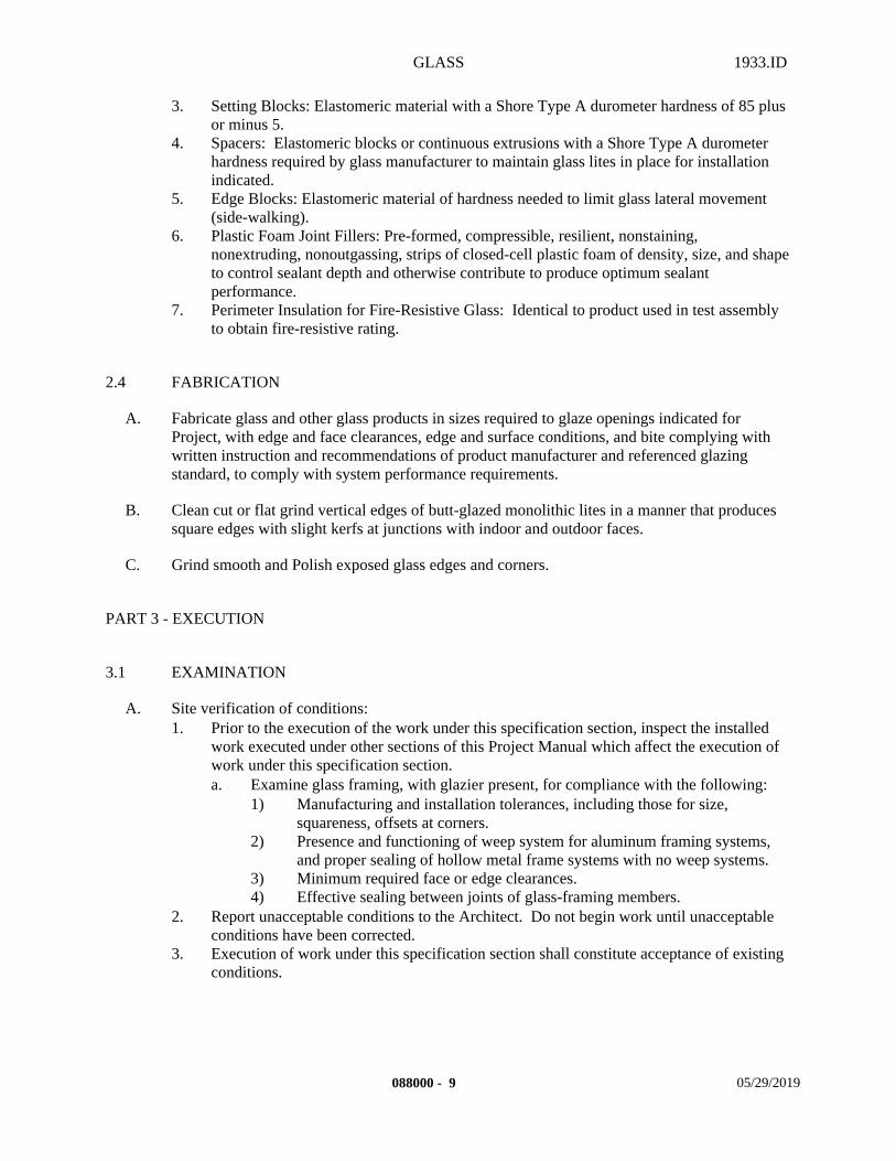
GLASS 1933.ID
3. Setting Blocks: Elastomeric material with a Shore Type A durometer hardness of 85 plus or minus 5.
4. Spacers: Elastomeric blocks or continuous extrusions with a Shore Type A durometer hardness required by glass manufacturer to maintain glass lites in place for installation indicated.
5. Edge Blocks: Elastomeric material of hardness needed to limit glass lateral movement (side-walking).
6. Plastic Foam Joint Fillers: Pre-formed, compressible, resilient, nonstaining, nonextruding, nonoutgassing, strips of closed-cell plastic foam of density, size, and shape to control sealant depth and otherwise contribute to produce optimum sealant performance.
7. Perimeter Insulation for Fire-Resistive Glass: Identical to product used in test assembly to obtain fire-resistive rating.
2.4 FABRICATION
A. Fabricate glass and other glass products in sizes required to glaze openings indicated for Project, with edge and face clearances, edge and surface conditions, and bite complying with written instruction and recommendations of product manufacturer and referenced glazing standard, to comply with system performance requirements.
B. Clean cut or flat grind vertical edges of butt-glazed monolithic lites in a manner that produces square edges with slight kerfs at junctions with indoor and outdoor faces.
C. Grind smooth and Polish exposed glass edges and corners.
PART 3 - EXECUTION
3.1 EXAMINATION
A. Site verification of conditions:1. Prior to the execution of the work under this specification section, inspect the installed
work executed under other sections of this Project Manual which affect the execution of work under this specification section.a. Examine glass framing, with glazier present, for compliance with the following:
1) Manufacturing and installation tolerances, including those for size, squareness, offsets at corners.
2) Presence and functioning of weep system for aluminum framing systems, and proper sealing of hollow metal frame systems with no weep systems.
3) Minimum required face or edge clearances.4) Effective sealing between joints of glass-framing members.
2. Report unacceptable conditions to the Architect. Do not begin work until unacceptable conditions have been corrected.
3. Execution of work under this specification section shall constitute acceptance of existing conditions.
088000 - 9 05/29/2019
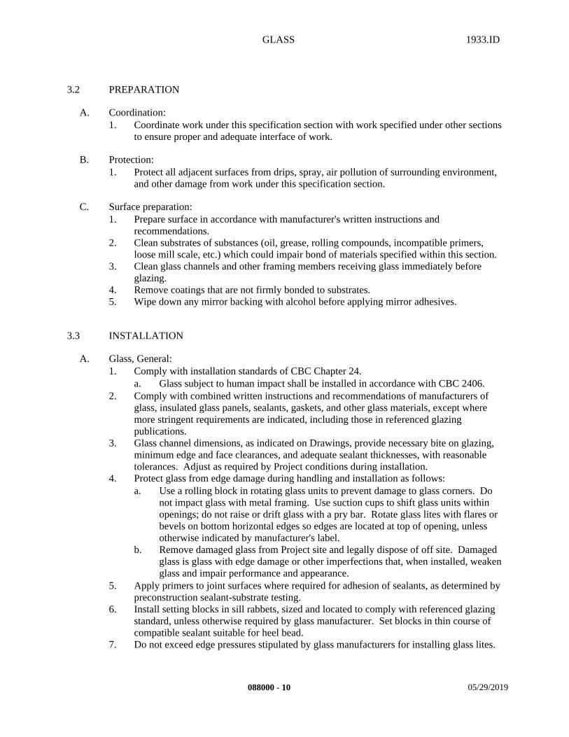
GLASS 1933.ID
3.2 PREPARATION
A. Coordination:1. Coordinate work under this specification section with work specified under other sections
to ensure proper and adequate interface of work.
B. Protection:1. Protect all adjacent surfaces from drips, spray, air pollution of surrounding environment,
and other damage from work under this specification section.
C. Surface preparation:1. Prepare surface in accordance with manufacturer's written instructions and
recommendations.2. Clean substrates of substances (oil, grease, rolling compounds, incompatible primers,
loose mill scale, etc.) which could impair bond of materials specified within this section.3. Clean glass channels and other framing members receiving glass immediately before
glazing.4. Remove coatings that are not firmly bonded to substrates.5. Wipe down any mirror backing with alcohol before applying mirror adhesives.
3.3 INSTALLATION
A. Glass, General:1. Comply with installation standards of CBC Chapter 24.
a. Glass subject to human impact shall be installed in accordance with CBC 2406.2. Comply with combined written instructions and recommendations of manufacturers of
glass, insulated glass panels, sealants, gaskets, and other glass materials, except where more stringent requirements are indicated, including those in referenced glazing publications.
3. Glass channel dimensions, as indicated on Drawings, provide necessary bite on glazing, minimum edge and face clearances, and adequate sealant thicknesses, with reasonable tolerances. Adjust as required by Project conditions during installation.
4. Protect glass from edge damage during handling and installation as follows:a. Use a rolling block in rotating glass units to prevent damage to glass corners. Do
not impact glass with metal framing. Use suction cups to shift glass units within openings; do not raise or drift glass with a pry bar. Rotate glass lites with flares or bevels on bottom horizontal edges so edges are located at top of opening, unless otherwise indicated by manufacturer's label.
b. Remove damaged glass from Project site and legally dispose of off site. Damaged glass is glass with edge damage or other imperfections that, when installed, weaken glass and impair performance and appearance.
5. Apply primers to joint surfaces where required for adhesion of sealants, as determined by preconstruction sealant-substrate testing.
6. Install setting blocks in sill rabbets, sized and located to comply with referenced glazing standard, unless otherwise required by glass manufacturer. Set blocks in thin course of compatible sealant suitable for heel bead.
7. Do not exceed edge pressures stipulated by glass manufacturers for installing glass lites.
088000 - 10 05/29/2019
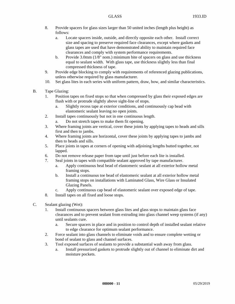
GLASS 1933.ID
8. Provide spacers for glass sizes larger than 50 united inches (length plus height) as follows:a. Locate spacers inside, outside, and directly opposite each other. Install correct
size and spacing to preserve required face clearances, except where gaskets and glass tapes are used that have demonstrated ability to maintain required face clearances and comply with system performance requirements.
b. Provide 3.0mm (1/8" nom.) minimum bite of spacers on glass and use thickness equal to sealant width. With glass tape, use thickness slightly less than final compressed thickness of tape.
9. Provide edge blocking to comply with requirements of referenced glazing publications, unless otherwise required by glass manufacturer.
10. Set glass lites in each series with uniform pattern, draw, bow, and similar characteristics.
B. Tape Glazing:1. Position tapes on fixed stops so that when compressed by glass their exposed edges are
flush with or protrude slightly above sight-line of stops.a. Slightly recess tape at exterior conditions, and continuously cap bead with
elastomeric sealant leaving no open joints.2. Install tapes continuously but not in one continuous length.
a. Do not stretch tapes to make them fit opening.3. Where framing joints are vertical, cover these joints by applying tapes to heads and sills
first and then to jambs.4. Where framing joints are horizontal, cover these joints by applying tapes to jambs and
then to heads and sills.5. Place joints in tapes at corners of opening with adjoining lengths butted together, not
lapped.6. Do not remove release paper from tape until just before each lite is installed.7. Seal joints in tapes with compatible sealant approved by tape manufacturer.
a. Apply continuous heal bead of elastomeric sealant at all exterior hollow metal framing stops.
b. Install a continuous toe bead of elastomeric sealant at all exterior hollow metal framing stops on installations with Laminated Glass, Wire Glass or Insulated Glazing Panels.
c. Apply continuous cap bead of elastomeric sealant over exposed edge of tape.8. Install tapes on all fixed and loose stops.
C. Sealant glazing (Wet):1. Install continuous spacers between glass lites and glass stops to maintain glass face
clearances and to prevent sealant from extruding into glass channel weep systems (if any) until sealants cure.a. Secure spacers in place and in position to control depth of installed sealant relative
to edge clearance for optimum sealant performance.2. Force sealant into glass channels to eliminate voids and to ensure complete wetting or
bond of sealant to glass and channel surfaces.3. Tool exposed surfaces of sealants to provide a substantial wash away from glass.
a. Install pressurized gaskets to protrude slightly out of channel to eliminate dirt and moisture pockets.
088000 - 11 05/29/2019
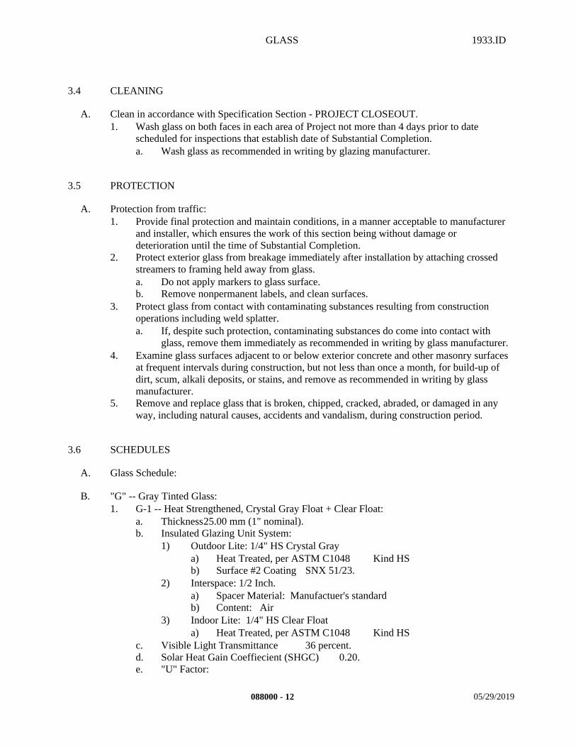
GLASS 1933.ID
3.4 CLEANING
A. Clean in accordance with Specification Section - PROJECT CLOSEOUT.1. Wash glass on both faces in each area of Project not more than 4 days prior to date
scheduled for inspections that establish date of Substantial Completion.a. Wash glass as recommended in writing by glazing manufacturer.
3.5 PROTECTION
A. Protection from traffic: 1. Provide final protection and maintain conditions, in a manner acceptable to manufacturer
and installer, which ensures the work of this section being without damage or deterioration until the time of Substantial Completion.
2. Protect exterior glass from breakage immediately after installation by attaching crossed streamers to framing held away from glass.a. Do not apply markers to glass surface.b. Remove nonpermanent labels, and clean surfaces.
3. Protect glass from contact with contaminating substances resulting from construction operations including weld splatter.a. If, despite such protection, contaminating substances do come into contact with
glass, remove them immediately as recommended in writing by glass manufacturer.4. Examine glass surfaces adjacent to or below exterior concrete and other masonry surfaces
at frequent intervals during construction, but not less than once a month, for build-up of dirt, scum, alkali deposits, or stains, and remove as recommended in writing by glass manufacturer.
5. Remove and replace glass that is broken, chipped, cracked, abraded, or damaged in any way, including natural causes, accidents and vandalism, during construction period.
3.6 SCHEDULES
A. Glass Schedule:
B. "G" -- Gray Tinted Glass:1. G-1 -- Heat Strengthened, Crystal Gray Float + Clear Float:
a. Thickness25.00 mm (1" nominal).b. Insulated Glazing Unit System:
1) Outdoor Lite: 1/4" HS Crystal Graya) Heat Treated, per ASTM C1048 Kind HSb) Surface #2 Coating SNX 51/23.
2) Interspace: 1/2 Inch.a) Spacer Material: Manufactuer's standardb) Content: Air
3) Indoor Lite: 1/4" HS Clear Floata) Heat Treated, per ASTM C1048 Kind HS
c. Visible Light Transmittance 36 percent. d. Solar Heat Gain Coeffiecient (SHGC) 0.20.e. "U" Factor:
088000 - 12 05/29/2019
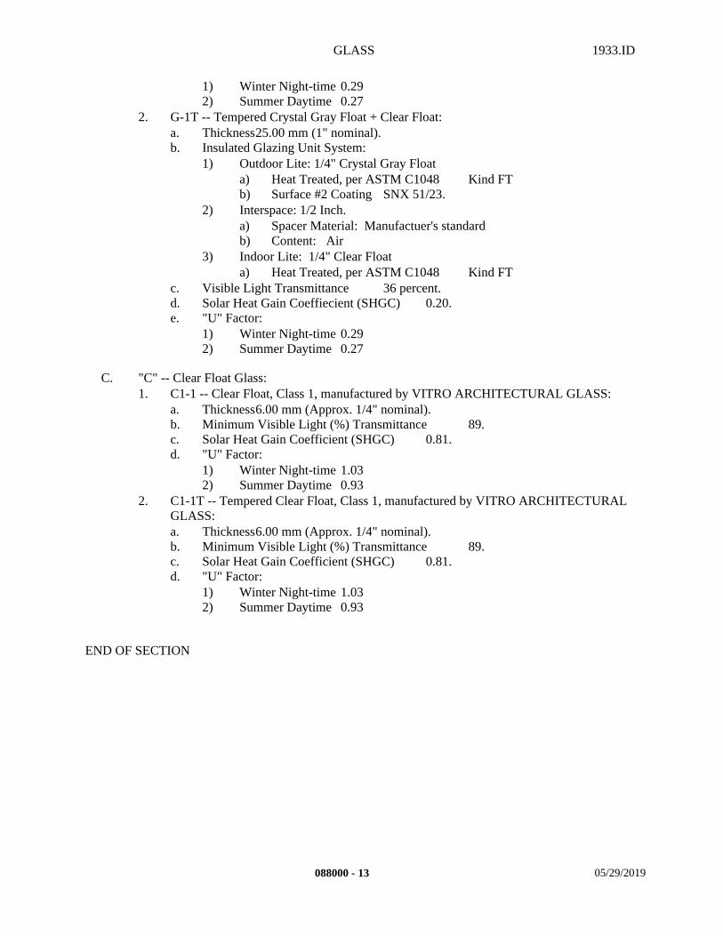
GLASS 1933.ID
1) Winter Night-time 0.292) Summer Daytime 0.27
2. G-1T -- Tempered Crystal Gray Float + Clear Float:a. Thickness25.00 mm (1" nominal).b. Insulated Glazing Unit System:
1) Outdoor Lite: 1/4" Crystal Gray Floata) Heat Treated, per ASTM C1048 Kind FTb) Surface #2 Coating SNX 51/23.
2) Interspace: 1/2 Inch.a) Spacer Material: Manufactuer's standardb) Content: Air
3) Indoor Lite: 1/4" Clear Floata) Heat Treated, per ASTM C1048 Kind FT
c. Visible Light Transmittance 36 percent.d. Solar Heat Gain Coeffiecient (SHGC) 0.20.e. "U" Factor:
1) Winter Night-time 0.292) Summer Daytime 0.27
C. "C" -- Clear Float Glass:1. C1-1 -- Clear Float, Class 1, manufactured by VITRO ARCHITECTURAL GLASS:
a. Thickness6.00 mm (Approx. 1/4" nominal).b. Minimum Visible Light (%) Transmittance 89.c. Solar Heat Gain Coefficient (SHGC) 0.81.d. "U" Factor:
1) Winter Night-time 1.032) Summer Daytime 0.93
2. C1-1T -- Tempered Clear Float, Class 1, manufactured by VITRO ARCHITECTURAL GLASS:a. Thickness6.00 mm (Approx. 1/4" nominal).b. Minimum Visible Light (%) Transmittance 89.c. Solar Heat Gain Coefficient (SHGC) 0.81.d. "U" Factor:
1) Winter Night-time 1.032) Summer Daytime 0.93
END OF SECTION
088000 - 13 05/29/2019

METAL FRAMING 1933.ID
SECTION 092216 – METAL FRAMING
PART 1 - GENERAL
1.1 SUMMARY
A. This Section includes the following:1. Provide all material, labor, equipment and services necessary to completely install all
metal framing materials (both Cold-Formed Framing and Lightgage Metal Framing), accessories and other related items necessary to complete the Project as indicated by the Contract Documents.
B. Related Sections: The following Project Manual Sections contain requirements that relate to this section:1. ALL DIVISION 00 SPECIFICATION SECTIONS.2. ALL DIVISION 01 SPECIFICATION SECTIONS.3. 03 15 14 DRILLED ANCHORS4. 03 30 00 CAST-IN-PLACE CONCRETE5. 05 12 00 STEEL AND FABRICATIONS6. 06 10 00 ROUGH CARPENTRY7. 06 41 23 MODULAR CASEWORK8. 07 51 13.01 BUILT-UP ROOFING9. 07 53 29 ELASTOMERIC MEMBRANE ROOFING10. 08 14 16 WOOD DOORS11. 09 29 00 GYPSUM BOARD12. 09 50 00 ACOUSTICAL CEILINGS13. 10 05 00 MISCELLANEOUS SPECIALTIES14. ALL SPECIFICATION SECTIONS IN THE FACILITY SERVICES SUBGROUP.
1.2 REFERENCES
A. In accordance with the following:1. AISI American Iron and Steel Institute2. ASTM American Society for Testing Materials3. AWS American Welding Society4. ICC International Code Council.
1.3 DEFINITIONS
A. Minimum Uncoated Steel Thickness: Minimum uncoated thickness of metal framing delivered to the Project site shall be not less than 95 percent of the thickness used in the metal framing design. Lesser thicknesses shall be permitted at bends due to cold forming.
092216 - 1 05/28/2019
METAL FRAMING 1933.ID
1.4 SYSTEM DESCRIPTION
A. Performance Requirements: It is the intention of this section and the drawings to form a guide for a complete framing system. Any items not specifically noted but necessary for a complete framing system shall be provided under this section.1. Wall systems shall accommodate tolerances, deflection of building structural members,
and clearances of intended openings.2. Fire-Test-Response Characteristics: Where indicated, provide metal framing materials
and construction identical to that of assemblies tested for fire resistance.a. Per ASTM E 119 "Test methods for Fire Tests of Building Construction and
Materials" by a testing and inspecting agency acceptable to Authorities Having Jurisdiction (AHJ), products used in the assembly shall carry a classification label from a testing laboratory acceptable to the AHJ.
1.5 SUBMITTALS
A. Submit in accordance with Specification Section - SUBMITTAL PROCEDURES:1. Product Data: For each type of product indicated.
a. Materials list of items proposed to be provided under this section.2. Quality Assurance/Control Submittals:
a. Test Reports:1) Current ICC ES Report.2) Welding inspection report per DSA/SSS "T & I" List.
b. Certificates:1) Welding certificates indicating qualifications.2) Mill certificates, per ICC AC46 "Acceptance Criteria for Cold-Formed Steel
Framing Members", indicating steel sheet complies with requirements, including base-metal thickness, yield strength, tensile strength, total elongation, and metallic-coating thickness. Comply also with CBC Section 2203A.1.
c. Manufacturer's Written Instructions:1) Manufacturer's written recommended installation procedures shall become
the basis for accepting or rejecting actual installation procedures on the work.
3. Closeout Submittals in accordance with the following:a. Warranty in accordance with Specification Section –WARRANTIES.
1.6 QUALITY ASSURANCE
A. Qualifications:1. Material Qualifications:
a. Galvanized and carbon sheet steel products formed from steel with a minimum yield stress of 33 ksi for 18 gage and lighter member and 50 ksi for 16 gage and heavier members.
b. All products shall be engineered to meet the latest Edition of the American Iron and Steel Institute (AISI), "North American Specification for the Design of Metal Steel Structural Members".
092216 - 2 05/28/2019
METAL FRAMING 1933.ID
c. All products manufactured shall comply with the CBC and AISI, and shall have a current ICC Evaluation Service Report (ICC ESR).1) AISI "Code of Standard Practice for Cold-Formed Steel Structural
Framing".2. Installer Qualifications:
a. Engage an experienced Installer who has successfully completed three (3) projects of similar scope and size to that indicated for this Project.
b. Welders shall be qualified for welding in horizontal, vertical, and overhead positions in accordance with AWS D1.3.
3. Manufacturer/Supplier Qualifications:a. Firm experienced in successfully producing/supplying products similar to that
indicated for this Project, with sufficient production/supply capacity to produce/supply required units without causing delay in the work.
B. Regulatory Requirements:1. In accordance with Specification Section - REGULATORY REQUIREMENTS, and the
following:a. CARB Materials and equipment used for this Project shall comply with the
current applicable regulations of the California Air Resources Board (CARB) and the Environmental Protection Agency (EPA), in the area where the project is located.
C. Meetings:1. Pre-Installation: Scheduled by the Contractor prior to the start of work.
a. Coordinate the work with other work being performed.b. Identify any potential problems that may impede planned progress and proper
installation of work regarding quality of installation and warranty requirements. 2. Progress: Scheduled by the Contractor during the performance of the work.
a. Review for proper installation of work progress.b. Identify any installation problems and acceptable corrective measures.c. Identify any measures to maintain or regain project schedule if necessary.
3. Completion: Scheduled by the Contractor upon proper completion of the work.a. Inspect and identify any problems that may impede issuance of warranties or
guaranties.b. Maintaining installed work until the Notice of Substantial Completion has been
executed.
1.7 DELIVERY, STORAGE, AND HANDLING
A. General: Steel Framing and related accessories shall be stored and handled in accordance with AISI "Code of Standard Practice for Cold-Formed Steel Structural Members".
B. Packing, shipping, handling, and unloading: 1. Products shall be handled in such a manner as to assure that they are free from corrosion,
deformation, dents, scratches and other damage.
C. Acceptance at Site: 1. Products must be in manufacturer's original unopened bundles and containers with labels
indicating brand name, size, and grade.2. Damaged products will not be accepted.
092216 - 3 05/28/2019
METAL FRAMING 1933.ID
D. Storage and protection: 1. Metal Framing and related accessories shall be stored and handled in accordance with the
AISI "Code of Standard Practice".2. Products shall be stored above ground on level platforms, six (6) inches above ground,
allowing air circulation under stacked units. a. Cover materials with protective waterproof covering providing for adequate air
circulation and ventilation.
1.8 PROJECT CONDITIONS
A. Existing Conditions: 1. Examine project and compare it with the drawings and specifications. Thoroughly
investigate and verify conditions under which the work is to be performed. No allowance will be made for extra work resulting from negligence or failure to be acquainted with all available information concerning conditions necessary to estimate the difficulty or cost of the work.
2. Field Measurements: Take and be responsible for field measurements as required. Report any significant differences between field dimensions and the contract document conditions to Architect.
3. Carefully coordinate work under this Section with that of the structural framing sections and details so that the interface between structural framing and non structural framing shall provide the lines and degree of finish shown and specified.
1.9 Describe special or extended warranty or bonds covering the conformance and performance of the work of the section. Coordinate with Contracting Requirements. Do not make statements that will limit or void those provisions. Ensure that procedures complement Division 01 Closeout Submittals. Include statements specific to this section that supplement or extend warranties contained in Div 01 WarrantiesWARRANTY
A. Contractor's General Warranty:1. In accordance with Specification Section - WARRANTIES.
B. Manufacturer’s Warranty:1. In accordance with manufacturer's written standard warranty:
a. Warranty Period One (1) Year.
C. Installer's Warranty:1. In accordance with the terms of the Specification Section - WARRANTIES:
a. Warranty period One (1) Year.
092216 - 4 05/28/2019
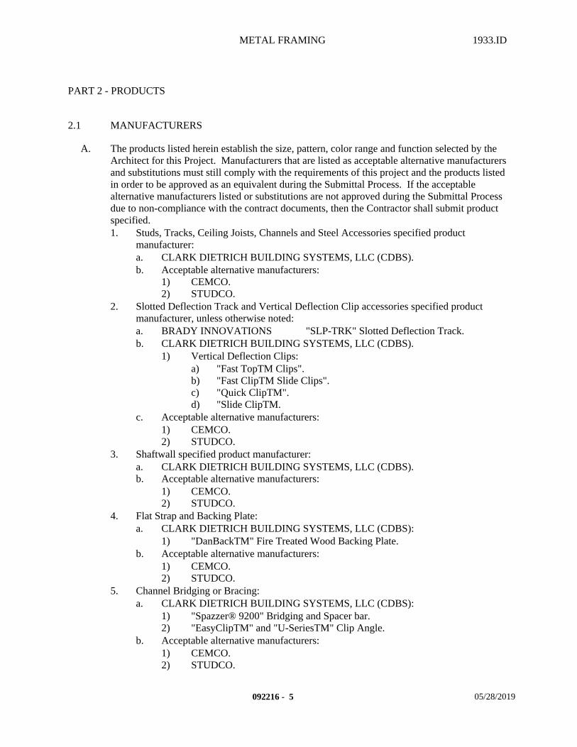
METAL FRAMING 1933.ID
PART 2 - PRODUCTS
2.1 MANUFACTURERS
A. The products listed herein establish the size, pattern, color range and function selected by the Architect for this Project. Manufacturers that are listed as acceptable alternative manufacturers and substitutions must still comply with the requirements of this project and the products listed in order to be approved as an equivalent during the Submittal Process. If the acceptable alternative manufacturers listed or substitutions are not approved during the Submittal Process due to non-compliance with the contract documents, then the Contractor shall submit product specified. 1. Studs, Tracks, Ceiling Joists, Channels and Steel Accessories specified product
manufacturer:a. CLARK DIETRICH BUILDING SYSTEMS, LLC (CDBS).b. Acceptable alternative manufacturers:
1) CEMCO.2) STUDCO.
2. Slotted Deflection Track and Vertical Deflection Clip accessories specified product manufacturer, unless otherwise noted:a. BRADY INNOVATIONS "SLP-TRK" Slotted Deflection Track. b. CLARK DIETRICH BUILDING SYSTEMS, LLC (CDBS).
1) Vertical Deflection Clips:a) "Fast TopTM Clips".b) "Fast ClipTM Slide Clips".c) "Quick ClipTM".d) "Slide ClipTM.
c. Acceptable alternative manufacturers:1) CEMCO.2) STUDCO.
3. Shaftwall specified product manufacturer:a. CLARK DIETRICH BUILDING SYSTEMS, LLC (CDBS).b. Acceptable alternative manufacturers:
1) CEMCO.2) STUDCO.
4. Flat Strap and Backing Plate:a. CLARK DIETRICH BUILDING SYSTEMS, LLC (CDBS):
1) "DanBackTM" Fire Treated Wood Backing Plate.b. Acceptable alternative manufacturers:
1) CEMCO.2) STUDCO.
5. Channel Bridging or Bracing:a. CLARK DIETRICH BUILDING SYSTEMS, LLC (CDBS):
1) "Spazzer® 9200" Bridging and Spacer bar.2) "EasyClipTM" and "U-SeriesTM" Clip Angle.
b. Acceptable alternative manufacturers:1) CEMCO.2) STUDCO.
092216 - 5 05/28/2019
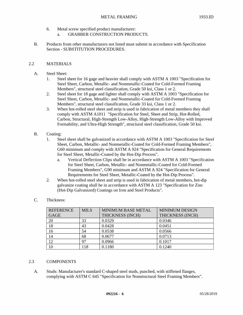
METAL FRAMING 1933.ID
6. Metal screw specified product manufacturer:a. GRABBER CONSTRUCTION PRODUCTS.
B. Products from other manufacturers not listed must submit in accordance with Specification Section - SUBSTITUTION PROCEDURES.
2.2 MATERIALS
A. Steel Sheet:1. Steel sheet for 16 gage and heavier shall comply with ASTM A 1003 "Specification for
Steel Sheet, Carbon, Metallic- and Nonmetallic-Coated for Cold-Formed Framing Members", structural steel classification, Grade 50 ksi, Class 1 or 2.
2. Steel sheet for 18 gage and lighter shall comply with ASTM A 1003 "Specification for Steel Sheet, Carbon, Metallic- and Nonmetallic-Coated for Cold-Formed Framing Members", structural steel classification, Grade 33 ksi, Class 1 or 2.
3. When hot-rolled steel sheet and strip is used in fabrication of metal members they shall comply with ASTM A1011 "Specification for Steel, Sheet and Strip, Hot-Rolled, Carbon, Structural, High-Strength Low-Alloy, High-Strength Low-Alloy with Improved Formability, and Ultra-High Strength", structural steel classification, Grade 50 ksi.
B. Coating:1. Steel sheet shall be galvanized in accordance with ASTM A 1003 "Specification for Steel
Sheet, Carbon, Metallic- and Nonmetallic-Coated for Cold-Formed Framing Members", G60 minimum and comply with ASTM A 924 "Specification for General Requirements for Steel Sheet, Metallic-Coated by the Hot-Dip Process".a. Vertical Deflection Clips shall be in accordance with ASTM A 1003 "Specification
for Steel Sheet, Carbon, Metallic- and Nonmetallic-Coated for Cold-Formed Framing Members", G90 minimum and ASTM A 924 "Specification for General Requirements for Steel Sheet, Metallic-Coated by the Hot-Dip Process".
2. When hot-rolled steel sheet and strip is used in fabrication of metal members, hot-dip galvanize coating shall be in accordance with ASTM A 123 "Specification for Zinc (Hot-Dip Galvanized) Coatings on Iron and Steel Products".
C. Thickness:
REFERENCE GAGE
MILS MINIMUM BASE METAL THICKNESS (INCH)
MINIMUM DESIGN THICKNESS (INCH)
20 33 0.0329 0.034618 43 0.0428 0.045116 54 0.0538 0.056614 68 0.0677 0.071312 97 0.0966 0.101710 118 0.1180 0.1240
2.3 COMPONENTS
A. Studs: Manufacturer's standard C-shaped steel studs, punched, with stiffened flanges, complying with ASTM C 645 "Specification for Nonstructural Steel Framing Members".
092216 - 6 05/28/2019
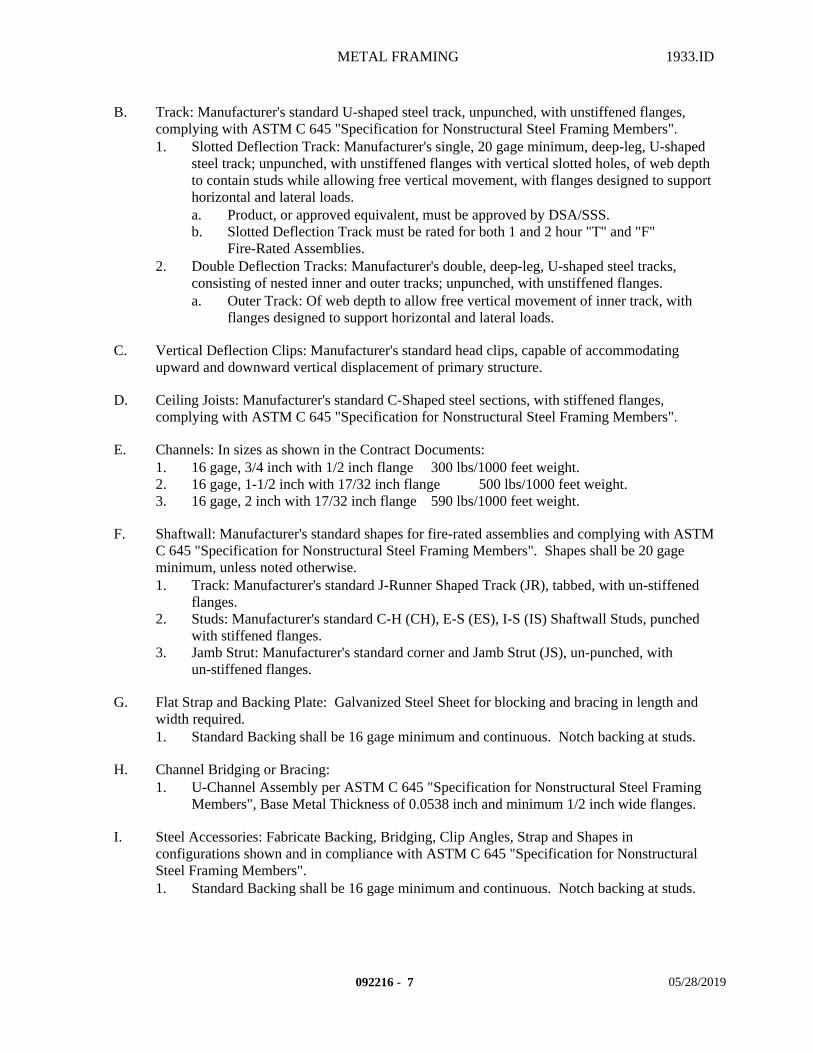
METAL FRAMING 1933.ID
B. Track: Manufacturer's standard U-shaped steel track, unpunched, with unstiffened flanges, complying with ASTM C 645 "Specification for Nonstructural Steel Framing Members".1. Slotted Deflection Track: Manufacturer's single, 20 gage minimum, deep-leg, U-shaped
steel track; unpunched, with unstiffened flanges with vertical slotted holes, of web depth to contain studs while allowing free vertical movement, with flanges designed to support horizontal and lateral loads.a. Product, or approved equivalent, must be approved by DSA/SSS.b. Slotted Deflection Track must be rated for both 1 and 2 hour "T" and "F"
Fire-Rated Assemblies.2. Double Deflection Tracks: Manufacturer's double, deep-leg, U-shaped steel tracks,
consisting of nested inner and outer tracks; unpunched, with unstiffened flanges.a. Outer Track: Of web depth to allow free vertical movement of inner track, with
flanges designed to support horizontal and lateral loads.
C. Vertical Deflection Clips: Manufacturer's standard head clips, capable of accommodating upward and downward vertical displacement of primary structure.
D. Ceiling Joists: Manufacturer's standard C-Shaped steel sections, with stiffened flanges, complying with ASTM C 645 "Specification for Nonstructural Steel Framing Members".
E. Channels: In sizes as shown in the Contract Documents:1. 16 gage, 3/4 inch with 1/2 inch flange 300 lbs/1000 feet weight.2. 16 gage, 1-1/2 inch with 17/32 inch flange 500 lbs/1000 feet weight.3. 16 gage, 2 inch with 17/32 inch flange 590 lbs/1000 feet weight.
F. Shaftwall: Manufacturer's standard shapes for fire-rated assemblies and complying with ASTM C 645 "Specification for Nonstructural Steel Framing Members". Shapes shall be 20 gage minimum, unless noted otherwise.1. Track: Manufacturer's standard J-Runner Shaped Track (JR), tabbed, with un-stiffened
flanges.2. Studs: Manufacturer's standard C-H (CH), E-S (ES), I-S (IS) Shaftwall Studs, punched
with stiffened flanges.3. Jamb Strut: Manufacturer's standard corner and Jamb Strut (JS), un-punched, with
un-stiffened flanges.
G. Flat Strap and Backing Plate: Galvanized Steel Sheet for blocking and bracing in length and width required.1. Standard Backing shall be 16 gage minimum and continuous. Notch backing at studs.
H. Channel Bridging or Bracing:1. U-Channel Assembly per ASTM C 645 "Specification for Nonstructural Steel Framing
Members", Base Metal Thickness of 0.0538 inch and minimum 1/2 inch wide flanges.
I. Steel Accessories: Fabricate Backing, Bridging, Clip Angles, Strap and Shapes in configurations shown and in compliance with ASTM C 645 "Specification for Nonstructural Steel Framing Members".1. Standard Backing shall be 16 gage minimum and continuous. Notch backing at studs.
092216 - 7 05/28/2019
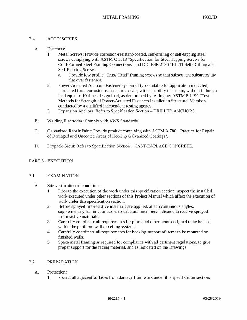
METAL FRAMING 1933.ID
2.4 ACCESSORIES
A. Fasteners:1. Metal Screws: Provide corrosion-resistant-coated, self-drilling or self-tapping steel
screws complying with ASTM C 1513 "Specification for Steel Tapping Screws for Cold-Formed Steel Framing Connections" and ICC ESR 2196 "HILTI Self-Drilling and Self-Piercing Screws".a. Provide low profile "Truss Head" framing screws so that subsequent substrates lay
flat over fasteners.2. Power-Actuated Anchors: Fastener system of type suitable for application indicated,
fabricated from corrosion-resistant materials, with capability to sustain, without failure, a load equal to 10 times design load, as determined by testing per ASTM E 1190 "Test Methods for Strength of Power-Actuated Fasteners Installed in Structural Members" conducted by a qualified independent testing agency.
3. Expansion Anchors: Refer to Specification Section – DRILLED ANCHORS.
B. Welding Electrodes: Comply with AWS Standards.
C. Galvanized Repair Paint: Provide product complying with ASTM A 780 "Practice for Repair of Damaged and Uncoated Areas of Hot-Dip Galvanized Coatings".
D. Drypack Grout: Refer to Specification Section – CAST-IN-PLACE CONCRETE.
PART 3 - EXECUTION
3.1 EXAMINATION
A. Site verification of conditions:1. Prior to the execution of the work under this specification section, inspect the installed
work executed under other sections of this Project Manual which affect the execution of work under this specification section.
2. Before sprayed fire-resistive materials are applied, attach continuous angles, supplementary framing, or tracks to structural members indicated to receive sprayed fire-resistive materials.
3. Carefully coordinate all requirements for pipes and other items designed to be housed within the partition, wall or ceiling systems.
4. Carefully coordinate all requirements for backing support of items to be mounted on finished walls.
5. Space metal framing as required for compliance with all pertinent regulations, to give proper support for the facing material, and as indicated on the Drawings.
3.2 PREPARATION
A. Protection:1. Protect all adjacent surfaces from damage from work under this specification section.
092216 - 8 05/28/2019
METAL FRAMING 1933.ID
2. Remove any fireproofing only as much of these materials as needed to complete installation of metal framing without reducing thickness of fire-resistive materials below that are required to obtain fire-resistance rating indicated. Protect remaining fire-resistive materials from damage.
B. Surface preparation:1. Prepare surface in accordance with manufacturer's written instructions and
recommendations.2. Clean substrates of substances (oil, grease, rolling compounds, incompatible primers,
loose mill scale, etc.) which could impair bond of materials specified within this section.3. Grout bearing surfaces uniform and level to ensure full contact of bearing flanges or track
webs on supporting concrete or masonry construction.
3.3 INSTALLATION
A. General:1. In accordance with drawings and manufacturer's written instructions and
recommendations, and procedures described in ASTM C 754 "Specification for Installation of Steel Framing Members to Receive Screw-Attached Gypsum Panel Products".
2. In accordance with approved submittals.3. In accordance with Regulatory Requirements.4. Set plumb, level, and square.5. Metal Framing may be shop or field fabricated for installation, or it may be field
assembled.
B. Layout:1. Lines shall be straight and true.2. Install Metal Framing according to ASTM C 754 "Specification for Installation of Steel
Framing Members to Receive Screw-Attached Gypsum Panel Products", unless more stringent requirements are indicated.
C. Installation:1. Install shop or field fabricated, Metal Framing and securely anchor to supporting
structure.a. Bolt or weld wall panels at horizontal and vertical junctures to produce flush, even,
true-to-line joints with maximum variation in plane and true position between fabricated panels not exceeding 1/16 inch in ten (10) feet.
2. Install Metal Framing and accessories plumb, square, and true to line, and with connections securely fastened, according to manufacturer's written recommendations and requirements of the Contract Documents.a. Cut framing members by sawing or shearing; do not torch cut.b. Fasten Metal Framing members by welding or screw fastening. Wire tying of
framing members is not permitted.1) Comply with AWS D1.3 requirements and procedures for welding,
appearance and quality of welds, and methods used in correcting welding work.
2) Locate mechanical fasteners and install, with screw penetrating joined members by not less than three exposed screw threads.
3) Beneath sheathing provide low-profile screw heads (i.e. "Wafer Head").
092216 - 9 05/28/2019
METAL FRAMING 1933.ID
4) Fasten both flanges of studs to track, unless otherwise indicated.3. Install framing members in one-piece lengths, unless splice connections are indicated for
track or tension members.4. Punched openings in studs must align when placed in final position.5. Install temporary bracing and supports to secure framing and support loads comparable in
intensity to those for which structure was designed. Maintain braces and supports in place, undisturbed, until entire integrated supporting structure has been completed and permanent connections to framing are secured.
6. Install horizontal bridging in wall studs, spaced in rows as indicated on the drawings. Fasten at each stud intersection.
7. Do not bridge building expansion and control joints with Metal Framing. Independently frame both sides of joints.
8. Install insulation in built-up exterior framing members, such as headers, sills, boxed joists, and multiple studs at openings, that are inaccessible on completion of framing work.
9. Fasten hole reinforcing plate over web penetrations that exceed size of manufacturer's standard punched openings.
10. Erection Tolerances: Install Metal Framing level, plumb, and true to line to a maximum allowable tolerance variation of 1/8 inch in 10 feet and as follows:a. Space individual framing members no more than plus or minus 1/8 inch from plan
location. Cumulative error shall not exceed minimum fastening requirements of sheathing or other finishing materials.
11. At all sound partitions, set floor runners in two 1/4 inch diameter continuous beads of acoustical sealant as prescribed in Specification Section - SEALANTS.
12. At all smoke barrier partitions, set floor and ceiling runners in two 1/4 inch diameter continuous beads of Class II Flame Spread and Smoke Developed rated acoustical sealant as prescribed in Specification Section - SEALANTS.
13. Install supplementary backing and bracing wherever walls or partitions are indicated to support equipment, services, casework, heavy trim and furnishings, and similar work requiring attachment to wall or partition. Comply with stud manufacturer's written instructions and industry standards.
14. Frame wall openings larger than 2-foot square with double stud at each jamb.15. Install continuous strapping to side of studs that do not receive sheathing at 3'-6" o.c.
vertically.
D. Ceiling Joist Installation:1. Align and install joist track and ceiling joists plumb, square, and true to line bearing on
supporting frame. Securely fasten connections according to manufacturer's written recommendations and requirements of the Contract Documents.
2. Install bridging at interval indicated on the drawings. Fasten at each joist intersection.
3.4 REPAIR / RESTORATION
A. Galvanizing Repairs: Prepare and repair damaged galvanized coatings on fabricated and installed Metal Framing with galvanized repair paint and manufacturer's written instructions.
B. Provide final protection and maintain conditions, in a manner acceptable to manufacturer and installer, that ensure Metal Framing is without damage or deterioration at time of Substantial Completion.
092216 - 10 05/28/2019
METAL FRAMING 1933.ID
3.5 FIELD QUALITY CONTROL
A. Site Tests:1. As required by Regulatory Requirements.
B. Inspection:1. As required by Regulatory Requirements.2. Schedule inspections and notify the Architect, Project Inspector and any other regulatory
agencies of the time at least 48 hours prior to the inspection.3. Project Inspector shall verify that all stud cavity walls are free of moisture and dry prior
to any other construction that encloses the wall cavity.
END OF SECTION
092216 - 11 05/28/2019

GYPSUM BOARD 1933.ID
SECTION 092900 – GYPSUM BOARD
PART 1 - GENERAL
1.1 SUMMARY
A. This Section includes the following:1. Provide all material, labor, equipment and services necessary to completely install all
gypsum board materials, suspension systems, furring, accessories and other related items necessary to complete the Project as indicated by the Contract Documents.
B. Related Sections: The following Project Manual Sections contain requirements that relate to this section:1. ALL DIVISION 00 SPECIFICATION SECTIONS.2. ALL DIVISION 01 SPECIFICATION SECTIONS.3. 06 10 00 ROUGH CARPENTRY4. 06 41 23 MODULAR CASEWORK5. 08 14 16 WOOD DOORS6. 09 22 16 METAL FRAMING7. 09 50 00 ACOUSTICAL CEILINGS8. 09 65 10 RESILIENT BASE AND ACCESSORIES9. 09 65 19 RESILIENT TILE10. 09 91 00 PAINTING 11. 10 05 00 MISCELLANEOUS SPECIALTIES12. 10 26 00 WALL AND CORNER GUARDS13. ALL SPECIFICATION SECTIONS IN THE FACILITY SERVICES SUBGROUP.
1.2 REFERENCES
A. Standards:1. In accordance with the following standards:
a. CISCA Ceilings & Interior Systems Construction Association.b. DITF Drywall Industry Trust Fund.c. GA Gypsum Association.d. MPI Master Painters Institutee. PDCA Painting and Decorating Contractors of America.f. PDSM Plaster and Drywall Systems Manual, ©1988 by BNI and McGraw-Hill,
Inc., Third Edition.
1.3 SYSTEM DESCRIPTION
A. Suspension System Design Requirements: In accordance with allowable values and properties assigned and approved by CBC.1. Lateral Load Design: ASCE 7, Chapter 13.2. Design Weight for lateral loads: Total Weight does not exceed four (4) pounds per square
foot, including air conditioning grilles and light fixtures.
092900 - 1 05/29/2019
GYPSUM BOARD 1933.ID
3. System is not to support lateral loads from partitions.4. Fasteners into concrete:
a. Must be capable of sustaining, without failure, a load equal to 200 lbs. tension for hangar wires and 440 lbs. tension for bracing wires.
5. Gypsum board suspended ceiling systems shall not support materials or building components other than grills, light fixtures, small electrical conduits, small ducts and the like.a. All such components shall be supported either directly from main runners, or by
supplemental framing, which is supported by main runners.b. No vertical loads other than gypsum board dead load shall be applied to
cross-furring.
1.4 SUBMITTALS
A. Submit in accordance with Specification Section - SUBMITTAL PROCEDURES:1. Product Data.
a. Gypsum board fastening schedule: Indicate type, size and spacing of fasteners for each type of framing and fire resistive condition.
b. Manufacturer's written recommended construction instructions or handbook for all gypsum board panel products and accessories.
c. Manufacturer's written recommended construction instructions or handbook for all suspension system products and accessories
d. Manufacturer's data for all types of gypsum board used on this project.2. Samples.
a. Provide 24 inch square samples for all textures for each level of finish.b. Provide 4 inch lineal samples of each piece of metal trim accessory specified.c. Provide 12 inch lineal samples of Suspension System components for each type of
system specified.3. Quality Assurance/Control Submittals:
a. Test Reports:1) Site Tests of suspended gypsum board ceiling fasteners and anchors
provided by Testing Agency.b. Certificates:
1) General Construction: Certificate signed by the Contractor on Contractor's letterhead.
2) Products: Certificates signed by manufacturers of gypsum board assembly components.
4. Closeout Submittals in accordance with Specification Section -PROJECT DOCUMENTS.a. Warranty in accordance with Specification Section - WARRANTIES.
1.5 QUALITY ASSURANCE
A. Qualifications:1. Material Qualifications:
a. Where fire-rated gypsum board assemblies are indicated, provide materials and construction identical to those of assemblies tested for fire resistance per ASTM E 119 "Test methods for Fire Tests of Building Construction and Materials", by an independent testing and inspecting agency acceptable to CSFM.
092900 - 2 05/29/2019
GYPSUM BOARD 1933.ID
b. Empty containers shall not be removed from site without the Project Inspector's approval.
2. Installer Qualifications:a. Engage an experienced Installer who has successfully completed three (3) projects
of similar scope and size to that indicated for this Project.1) Helpers and apprentices used for such work shall be under full and constant
supervision at all times by thoroughly skilled gypsum board installers.2) In the acceptance or rejection of installed gypsum board, no allowance will
be made for lack of skill on the part of installers.
B. Regulatory Requirements:1. In accordance with Specification Section - REGULATORY REQUIREMENTS, and the
following:a. CARB Materials and equipment used for this Project shall comply with the
current applicable regulations of the California Air Resources Board (CARB) and the Environmental Protection Agency (EPA), in the area where the project is located.
b. IR Interpretation of Regulations.
C. Certificates:1. General Construction: Contractor to certify that work provided, meets or exceeds the
requirements of this section.2. Manufacturers of gypsum board assembly components certify that their products comply
with specified requirements.a. Certify that all adhesive and compound materials have a good shelf life longer than
the construction period of this project.
D. Mockups:1. Before starting the finishing of gypsum board surfaces, install mockups of at least 100 sq.
ft. in surface area to demonstrate aesthetic effects and qualities of materials and execution.a. Install mockups for the following applications:
1) All surfaces without finish texture.2) All surfaces without finish texture to be painted.3) All surfaces with finish texture to be painted.
b. Simulate finished lighting conditions for review of mockups.c. Approved mockups may become part of the completed Work if undisturbed at time
of Substantial Completion.
E. Meetings:1. Pre-Installation: Scheduled by the Contractor prior to the start of work.
a. Coordinate the work with other work being performed.b. Identify any potential problems that may impede planned progress and proper
installation of work regarding quality of installation and warranty requirements. 2. Progress: Scheduled by the Contractor during the performance of the work.
a. Review for proper installation of work progress.b. Identify any installation problems and acceptable corrective measures.c. Identify any measures to maintain or regain project schedule if necessary.
3. Completion: Scheduled by the Contractor upon proper completion of the work.
092900 - 3 05/29/2019
GYPSUM BOARD 1933.ID
a. Inspect and identify any problems that may impede issuance of warranties or guaranties.
b. Maintain installed work until the Notice of Substantial Completion has been executed.
1.6 DELIVERY, STORAGE, AND HANDLING
A. Packing, shipping, handling, and unloading: 1. Products shall be handled in such a manner as to assure that they are free from dents,
scratches and other damage.
B. Acceptance at Site: 1. Products must be in manufacturer's original unopened containers with labels indicating
brand name, model, and grade. 2. Damaged products will not be accepted.
C. Storage and protection: 1. Products shall be stored above ground on level platforms, six (6) inches above ground,
allowing air circulation under stacked units. a. Cover materials with protective waterproof covering providing for adequate air
circulation and ventilation.
1.7 WARRANTY
A. Contractor's General Warranty:1. In accordance with Specification Section - WARRANTIES.
B. Manufacturer’s Warranty:1. In accordance with manufacturer's written standard warranty:
a. Warranty Period One (1) Year.
C. Installer's Warranty:1. In accordance with the terms of the Specification Section - WARRANTIES:
a. Warranty period One (1) Year.
PART 2 - PRODUCTS
2.1 MANUFACTURERS
A. These products listed herein establish the size, pattern, color range and function selected by the Architect for this Project. Manufacturers that are listed as acceptable alternative manufacturers and substitutions must still comply with the requirements of this project and the products listed in order to be approved as an equivalent during the Submittal Process. If the acceptable alternative manufacturers listed or substitutions are not approved during the Submittal Process due to non-compliance with the contract documents, then the Contractor shall submit product specified. 1. Specified gypsum board products manufacturer:
092900 - 4 05/29/2019
GYPSUM BOARD 1933.ID
a. NATIONAL GYPSUM COMPANY.1) Wallboard "REGULAR".
b. Acceptable alternative manufacturers:1) PABCO:
a) Wallboard "REGULAR" AND "TYPE X".2) UNITED STATES GYPSUM COMPANY - "SHEETROCK".
a) Wallboard "SW EDGE".2. Specified gypsum board accessories product manufacturer:
a. Prep. Coat (Drywall Primer):1) WESTPAC MATERIALS "PREP COAT".2) Acceptable alternative manufacturer:
a) UNITED STATES GYPSUM - SECUROCK First Coat Primer.b. Primer-Surfacer: "TUFF-HIDE".
1) UNITED STATES GYPSUM COMPANY. c. Other Accessories:
1) CLARK DIETRICH BUILDING SYSTEMS, LLC (CDBS).3. Specified revel molding products manufacturer:
a. FRY REGLET CORPORATION.
B. Products from other manufacturers not listed must submit in accordance with Specification Section - SUBSTITUTION PROCEDURES.
2.2 MATERIALS
A. Furring:1. Metal Angles: 24 gage galvanized steel.
a. 1-3/8 inch x 7/8 inch 190 lbs./1000 feet weight.2. Cold Rolled Channels: 16 gage galvanized steel
a. For furred walls and ceilings.1) 3/4 inch x 1/2 inch flange: 300 lbs./1000 feet weight.2) 1-1/2 inch x 17/32 inch flange: 500 lbs./feet weight.3) 2 inch x 17/32 inch flange: 590 lbs./1000 feet weight.
3. Resilient Channels (USG's RC-1): 25 gage corrosion resistant steel.a. Pre-punched holes at 4 inches on center in the flange to facilitate screw attachment
only into framing. For improving sound transmission loss through framed partitions and ceilings.1) 1/2 inch flange x 2-1/2 inch overall w/1-1/2 inch offset flange x 1/2 inch
offset:a) 200 lbs./1000 feet weight.
4. Zee Channels: 24 gage corrosion resistant steel.a. 1 inch thick x 7/8 inch x 1-1/4 inch 224 lbs./1000 feet weight.b. 1-1/2 inch x 7/8 inch x 1-1/4 inch 269 lbs./1000 feet weight.c. 2 inch x 7/8 inch x 1-1/4 inch 313 lbs./1000 feet weight.d. 3 inch x 7/8 inch x 1-1/4 inch 400 lbs./1000 feet weight.
5. Hat Channels:a. 7/8 inch x 2-9/16 inch 276 lbs./1000 feet weight (25 gage).b. 7/8 inch x 2-9/16 inch 515 lbs./1000 feet weight (20 gage).
6. Channel Clips:
092900 - 5 05/29/2019
GYPSUM BOARD 1933.ID
a. Pre-formed galvanized wire used for attaching metal furring channels to cold rolled channels and single gypsum panel systems only.1) 1-1/2 inch x 2-3/4 inch 38 lbs./1000 feet weight.
B. Suspension System:
C. Wallboard: For interior walls and ceilings.1. Standard: In accordance with ASTM C 1396 "Standard Specification for Gypsum
Board".2. Size: See drawings for specific thickness locations:
a. 5/8 inch thick by 4 foot wide maximum by practical length to minimize joints.1) When curved walls are indicated on the drawings, provide multiple layers of
1/4 inch & 3/8 inch thick by 4 foot wide maximum by practical length to minimize joints.
3. Long Edges: SW Tapered.4. Core Type:
a. Non-Fire Rated: Regular.b. Fire Rated Type X at fire-resistive-rated assemblies.
5. Finish: Natural-finish face paper suitable for paint, wallpaper or other decorations.
D. Metal Accessories:1. Corner Beads:
a. Outside Corner, 1-1/4 inch x 1-1/4 inch galvanized:1) CDBS / USG "Dur-A-Bead" #103.
2. Edge Trim:a. "U"-Shaped 1 inch galvanized CDBS / USG #200-A, size to fit gypsum board.b. "L"-Shaped 1 inch galvanized CDBS / USG #200-B, size to fit gypsum board.
1) When "U"-Shaped molding above cannot be used.3. Control Joint:
a. 1-3/4" wide, 1/4" wide center channel with removable tape strip:1) CDBS / USG #093.
4. Reveal Moldings (Aluminum Trim): Moldings listed below are manufactured by FRY REGLETS, or approved equivalent.a. Reveal Molding Sized to fit gypsum board.b. "L" Trim Molding Sized to fit gypsum board.c. "F" Reveal Molding Sized to fit gypsum board.d. Snap-In Reveal Sized to fit gypsum board.e. "Z" Reveal Molding Sized to fit gypsum board.f. Reveal Channel Screed Sized to fit gypsum board.g. "F" Reveal Sized to fit gypsum board.h. "T" Molding Sized to fit gypsum board.
2.3 ACCESSORIES
A. Water:1. Clean, fresh and free from deleterious amounts of foreign material.
B. Fasteners:
092900 - 6 05/29/2019
GYPSUM BOARD 1933.ID
1. At Gypsum Board: In accordance with the manufacturer's written recommendations and the following:a. Nails: In accordance with CBC Chapter 7 and ASTM C 514 "Standard
Specification for Nails for the Application of Gypsum Board".b. Screws: In accordance with CBC Chapter 7, ASTM C 1002 "Standard
Specification for Steel Self-Piercing Tapping Screws for the Application of Gypsum Panel Products or Metal Plaster Bases to Wood Studs or Steel Studs", type S, G, and W, and ASTM C 954 "Standard Specification for Steel Drill Screws for the Application of Gypsum Panel Products or Metal Plaster Bases to Steel Studs from 0.033 in. (0.84 mm) to 0.112 in. (2.84 mm) in Thickness", Type S-12.1) Provide "Bugle Head" screws that help prevent damage to the gypsum core
and face paper.c. Adhesives: In accordance with ASTM C 475 "Standard Specification for Joint
Compound and Joint Tape for Finishing Gypsum Board".1) Commercial adhesives bridging minor irregularities in the base or framing
at "non-fire-rated" construction.a) In accordance with ASTM C 557 "Standard Specification for
Adhesives for Fastening Gypsum Wallboard to Wood Framing".2. At Suspension Systems:
a. Wood Construction:1) Eye screws, minimum 1/4 inch diameter, 1-1/4 inch minimum embedment.2) Staples, 1-1/2 inch x 0.148 inch diameter (9 gage).3) Nails, "STRONGHOLD-J" nails.
C. Joint reinforcement tape and joint compounds:1. In accordance with ASTM C 474 "Standard Test Methods for Joint Treatment Materials
for Gypsum Board Construction" and C 475 "Standard Specification for Joint Compound and Joint Tape for Finishing Gypsum Board", and Gypsum Board Manufacturer's written recommendations of both the manufacturers of sheet products and of joint treatment materials for each application indicated.a. Joint Tapes:
1) Paper reinforcing tape, unless otherwise indicated.2) Polymer-coated, open glass-fiber mesh for cementitious backer units.
b. Setting-Type Joint compounds for gypsum board: Factory-packaged, job-mixed, chemical-hardening powder products formulated for uses indicated.1) When used for taping and filling only, use formulation that is compatible
with other joint compounds applied over it.2) When used for pre-filling gypsum board joints, use formulation
recommended by gypsum board manufacturer for this purpose.3) When used for filling joints and treating fasteners of water-resistant gypsum
backing board behind base for ceramic tile, use formulation recommended by the gypsum board manufacturer for this purpose.
4) When used for topping compound, use sandable formulation.
D. Prep. Coat: Provide a preparation coat of the specified material to gypsum board surfaces to be decorated with all paints.
E. Primer-Surfacer: “TUFF-HIDE” by USG, Interior White Latex High Build Spray for a smoother paint finish over all types of drywall, 9.8 to 13 mils DFT in one spray application
092900 - 7 05/29/2019
GYPSUM BOARD 1933.ID
F. Textured Finish Coats: Gypsum Board manufacturer supplying the products to this project shall also supply the Texture Finishes to provide distinctive appearance and surface decoration to gypsum board panel walls and ceilings, and as scheduled at the end of this Specification Section.
G. Other Materials: All other miscellaneous materials, not specifically described, but required for a complete and proper installation of gypsum board, shall be as selected by the Contractor subject to the approval of the Architect.
PART 3 - EXECUTION
3.1 EXAMINATION
A. Site verification of conditions:1. Prior to the execution of the work under this specification section, inspect the installed
work executed under other sections of this Project Manual which affect the execution of work under this specification section.
2. Report unacceptable conditions to the Architect. Do not begin work until unacceptable conditions have been corrected.
3. Execution of work under this specification section shall constitute acceptance of existing conditions.
3.2 PREPARATION
A. Coordination:1. Coordinate work under this specification section with work specified under other sections
to ensure proper and adequate interface of work.2. Coordinate proper placement of ceiling mounted tracks, accessories, light fixtures,
HVAC, registers and other items, which are to be integrated with gypsum board ceilings.
B. Protection:1. Do not begin work until all rooms have been protected against the weather, and the
building is covered and fully enclosed. Wet gypsum board after installation shall be removed and replaced at no extra cost to the Owner.
2. Protect all adjacent surfaces from drips, spray, air pollution of surrounding environment, and other damage from work under this specification section.
C. Surface preparation:1. Prepare surface in accordance with manufacturer's written instructions and
recommendations.2. Clean substrates of substances (oil, grease, rolling compounds, incompatible primers,
loose mill scale, etc.) which could impair bond of materials specified within this section.
3.3 INSTALLATION
A. General:
092900 - 8 05/29/2019
GYPSUM BOARD 1933.ID
1. In accordance with manufacturer's written instructions and recommendations unless specifically noted otherwise.
2. In accordance with Regulatory Requirements.a. DSA's IR 25-3 "Drywall Ceiling Suspension Conventional Construction-One
Layer".3. Set plumb, level, and square.
B. Layout:1. Lines shall be straight and true.2. Control Joints:
a. Layout in accordance with GA-234-08 for both Non-Rated and Rated wall and ceiling conditions as follows:1) Provide Control Joints at in an uninterupted straight plane exceeding 30 ft.
in length and total area between control joints, such that no area exceeds 900 sq.ft.
C. Suspension System Installation: In accordance with DSA's IR 25-3.
D. Furring Channels:1. Attach hat channels at 16" o.c. to framing members at 24" o.c. maximum with one 1-1/2"
Type "G" screw at each bearing point. Stagger screws to opposite sides at every bearing surface.
E. Gypsum Board:1. General:
a. During Winter Weather Installation periods, follow the GA-220 GYPSUM BOARD WINTER RELATED INSTALLATION RECOMMENDATIONS.
2. Install in accordance with CBC Chapter 25, DITF and GA recommendations, gypsum board panel manufacturer's written recommendations and in accordance with fire-rated design numbers.a. At Ceilings and Soffits:
1) At gypsum board ceilings and soffit areas, install the ceiling prior to installing the walls.
2) Float the interior ceiling angles, and where permitted by code,3. Install gypsum board panels horizontally on walls, floor to ceiling.4. At metal frames terminate wall board panel edge inside frame. Do not terminate gypsum
board panel edge against metal frame trim unless otherwise indicated.
F. Cutting:1. Cut gypsum board panels by scoring and breaking or by sawing, working from the face
side.a. When cutting by scoring, cut through the face paper and then snap the panel back
away from the cut face; then break the backpaper by snapping the panel in the reverse direction or by cutting the back paper.
2. Smooth all cut ends and edges of panels as necessary to obtain a smooth joint.3. For cut-outs in panels for pipes, fixtures, and other small openings, make holes and
cut-outs by sawing or by such other method as will not fracture the core or tear the covering and with such accuracy that plates, escutcheons, or trim will cover the edges.
4. The use of "score-and-knockout" method will not be permitted.
G. Metal Accessories:
092900 - 9 05/29/2019
GYPSUM BOARD 1933.ID
1. Corner Beads:a. Install at all corners with galvanized screws at nine (9) inch intervals in both
flanges with fasteners placed opposite one another the full length of the corner bead. Clinch-on fastening is not allowed.1) Fasteners shall be driven below the anticipated finished joint compound
surface.b. Install in one piece except when length of corner exceeds stock lengths – then put
splice up high away from people traffic.2. Edge Trim: Install at all exposed joints where gypsum board panels abut another material
with galvanized screws at nine (9) inch intervals the full length of the edge trim. Clinch-on fastening is not allowed.a. Fasteners shall be driven below the anticipated finished joint compound surface.b. Provide joint sealer in accordance with Specification Section – SEALANTS.
1) Provide fire sealant in accordance with Specification Section – FIRSTOPPING or Specification Section – SEALANTS, when the wall or ceiling is part of a fire-rated situation.
3. Control Joints:a. Install at 30'-0" o.c. maximum at all interior walls or partitions with uninterrupted
planes that exceed 30' in length.1) Opening frames that are full height of wall or partition may be considered a
control joint.b. Install at 50'-0" o.c. maximum at all interior ceilings and shall not exceed 2,500
sq.ft. in total area with perimeter relief.c. Install at 30'-0" o.c. maximum at all interior ceilings and shall not exceed 900 sq.ft.
in total area without perimeter relief.
H. Fastening:1. Properly space all fasteners in careful accordance with the manufacturer's written
recommendations and code requirements, with heads driven slightly below the surface for proper cementing, but without breaking the paper face.
2. Loosely butt all joints to be taped; firmly butt all joints to be left untreated.3. Stagger all end joints and the joints between panels to achieve a maximum of bridging
and a minimum of continued joints.
I. Taping and Finishing:1. First Coat:
a. Spread compound evenly over all joints, using suitable tools designed for the purpose.
b. Fill all joint recesses and metal trim.c. Center the reinforcing tape on the joint and press into the fresh compound at all
joints, wiping down with sufficient pressure to remove excess compound but leaving sufficient compound under the tape for proper bond.
d. Feather all edges and leave the surface free from blisters and tape wrinkles.e. Apply compound to all fastener recesses, leaving flush with the adjacent surfaces.f. Fold reinforcing tape along its centerline and apply to all interior angles, following
the same procedure as for joints.g. Surfaces shall be free of excess joint compound.
2. Second Coat:a. Lightly sand the dry compound with fine sandpaper to remove all irregularities.b. Apply a second coat of compound to all joints, feathering approximately three
inches beyond edges of tape.
092900 - 10 05/29/2019
GYPSUM BOARD 1933.ID
c. Apply second coat to all fastener recesses.d. Surfaces shall be free of excess joint compound.
3. Third Coat:a. Lightly sand the dry compound with fine sandpaper to remove irregularities.b. Apply final skim coat, feathering out approximately two inches beyond second
coat.c. Third coat all fastener recesses and metal trim, and all interior angles; allow to
dry.d. Surfaces shall be free of excess joint compound.
J. Prep. Coat (Drywall Primer):1. Apply Prep. Coat material at approximately 200 sq.ft. per gallon for all painted wall
surfaces. Follow manufacturer's written recommendations for proper preparation of material, mixing and installation at recommended minimum coverage rates.a. For smooth walls with no texture, provide airless sprayer application in accordance
with manufacturer's written recommendations. 1) Fine finish: Sand wall surface with 220 grit mesh screen after application of
Prep. Coat. Do not oversand!b. For textured walls: Provide roller application with a 3/8" to 1/2" nap roller before
texture application is applied in accordance with manufacturer's written recommendations.
K. Primer - Surfacer:1. Apply Primer - Surfacer material at manufacturer's written recommendations for proper
preparation of material, mixing and installation, and at recommended minimum coverage rates.a. For smooth walls with no texture, provide airless sprayer application in accordance
with manufacturer's written recommendations. 1) Fine finish: Sand wall surface with 220 grit mesh screen after application of
Primer - Surfacer. Do not oversand!b. For textured walls: Provide roller application with a 3/8" to 1/2" nap roller before
texture application is applied in accordance with manufacturer's written recommendations.
L. Textured Finish Coats: After taping and finishing, apply Textured Finish Coats as indicated in the schedule at the end of this Specification Section.
3.4 FIELD QUALITY CONTROL
A. Site Tests:1. Testing Agency: The Owner's Testing Laboratory Agency shall perform field tests and
Inspections and prepare test reports.a. Testing and inspecting of completed installations of suspended gypsum board
ceiling fasteners and anchors shall take place in successive stages, in areas of extent and using methods as follows. Do not proceed with installations of gypsum board ceiling hangers for the next area until test results for previously completed installations of acoustical panel ceiling hangers show compliance with requirements.
2. Extent of Each Test Area: When installation of ceiling suspension systems on each floor has reached 20 percent completion but no panels have been installed:
092900 - 11 05/29/2019
GYPSUM BOARD 1933.ID
a. Concrete Anchors:1) Must be capable of sustaining, without failure, a load equal to 200 lbs.
tension for hanger wires and 440 lbs. tension for bracing wires by construction as determined by testing according to ASTM E 488 "Test Methods for Strength of Anchors in Concrete and Masonry Elements", by a qualified independent testing agency.a) Hanger Wire Anchors 1 in 10 must be field tested.b) Bracing Wire Anchors 1 in 2 must be field tested.
3. Remove and replace gypsum board ceiling hangers where test results indicate that they do not comply with specified requirements.
4. Additional testing and inspecting, at Contractor's expense, will be performed to determine compliance of replaced or additional work with specified requirements.a. When testing discovers fasteners and anchors that do not comply with
requirements, testing agency will test those anchors ot previously tested until 20 pass consecutively and then will resume initial testing frequency.
B. Inspection:1. As required by Regulatory Requirements.2. Schedule inspections and notify the Architect, Project Inspector and any other regulatory
agencies of the time at least 48 hours prior to the inspection.3. No work shall be without the inspections required by Regulatory Requirements.
3.5 CLEANING
A. Clean in accordance with Specification Section - PROJECT CLOSEOUT.1. Clean any soiled surfaces immediately.2. Clean any soiled surfaces at the end of each day, minimum.3. Finish shall be clean and ready for the application of any additional finishes.4. In accordance with manufacturer's written instructions and recommendations.
3.6 PROTECTION
A. Protection from weather:1. Protect newly installed work from moisture after installation.
B. Protection from traffic: 1. Provide final protection and maintain conditions, in a manner acceptable to manufacturer
and installer, which ensures the work of this section being without damage or deterioration until the time of Substantial Completion.
3.7 SCHEDULES
A. The following textured finish coat finishes shall be applied to the board surfaces within the scope of this section prior to covering with other finish materials. 1. Refer to the Material and Finish Schedule for specific locations of each substrate finish. 2. Where no specific substrate finish is called for on the drawings, select the appropriate
level of substrate finish from the descriptions below for the final finish material.
092900 - 12 05/29/2019
GYPSUM BOARD 1933.ID
3. Where no determination can be made from the descriptions below, provide a minimum of GB-2 substrate finish.
4. Where sound, smoke control or fire-ratings are required, details of construction shall be in accordance with reports of tested assemblies meeting the requirements.
B. GB-1 - Architect's Finish Designation:1. Level 5 - GYPSUM ASSOCIATION'S LEVEL OF GYSPSUM BOARD FINISH:
a. All joints and interior angles shall have tape embedded in joint compound and two separate coats of joint compound applied over all flat joints and one separate coat of joint compound applied over interior angles. Fastener heads and accessories shall be covered with three separate coats of joint compound. A thin skim coat of joint compound or a material manufactured especially for this purpose, shall be applied to the entire surface. The surface shall be smooth and free of tool marks and ridges.
b. Architect’s Finish:1) Uniformly smooth and ready to receive light grade wallcoverings, or fine
textured finishes, or flat, semi-gloss, or gloss paints over flat surfaces.2) Use “Fog and Splatter” fine textured finish where walls and ceilings are
scheduled to be painted, unless otherwise noted.
C. GB-2 - Architect's Finish Designation:1. Level 4 - GYPSUM ASSOCIATION'S LEVEL OF GYSPSUM BOARD FINISH:
a. All joints and interior angles shall have tape embedded in joint compound and two separate coats of joint compound applied over all flat joints and one separate coat of joint compound applied over interior angles. Fastener heads and accessories shall be covered with three separate coats of joint compound. All joint compound surfaces shall be smooth and free of tool marks and ridges.
b. Architect’s Finish:1) Uniformly smooth and ready to receive light textures (“Spray-Splatter”,
“Orange Peel” (light or heavy) ‘Stipple” or “Skip Trowel” finishes), or medium grade wall-coverings.
2) Use “Orange Peel” light texture finish when walls and ceilings are scheduled to be painted, unless otherwise noted.
D. GB-3 - Architect's Finish Designation:1. Level 2 - GYPSUM ASSOCIATION'S LEVEL OF GYSPSUM BOARD FINISH:
a. All joints and interior angles shall have tape embedded in joint compound and wiped with a joint knife leaving a thin coating of joint compound over all joints and interior angles. Fastener heads and accessories shall be covered with a coat of joint compound. Surface shall be free of excess joint compound. Tool marks and ridges are acceptable. Joint compound applied over the body of the tape at the time of tape embedment shall be considered a separate coat of joint compound and shall satisfy the conditions of this level.
b. Architect’s Finish:1) Total surface must be sufficiently smooth to create a good bonding plane
acceptable for installation of scheduled materials (ceramic tile, plywood, acoustical tile or similar materials).
E. GB-4 - Architect's Finish Designation:1. Level 3 - GYPSUM ASSOCIATION'S LEVEL OF GYSPSUM BOARD FINISH:
092900 - 13 05/29/2019
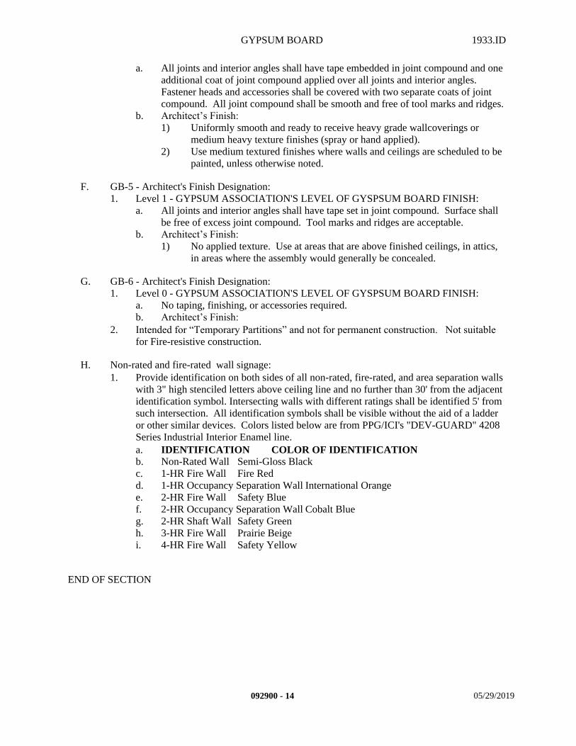
GYPSUM BOARD 1933.ID
a. All joints and interior angles shall have tape embedded in joint compound and one additional coat of joint compound applied over all joints and interior angles. Fastener heads and accessories shall be covered with two separate coats of joint compound. All joint compound shall be smooth and free of tool marks and ridges.
b. Architect’s Finish:1) Uniformly smooth and ready to receive heavy grade wallcoverings or
medium heavy texture finishes (spray or hand applied).2) Use medium textured finishes where walls and ceilings are scheduled to be
painted, unless otherwise noted.
F. GB-5 - Architect's Finish Designation:1. Level 1 - GYPSUM ASSOCIATION'S LEVEL OF GYSPSUM BOARD FINISH:
a. All joints and interior angles shall have tape set in joint compound. Surface shall be free of excess joint compound. Tool marks and ridges are acceptable.
b. Architect’s Finish:1) No applied texture. Use at areas that are above finished ceilings, in attics,
in areas where the assembly would generally be concealed.
G. GB-6 - Architect's Finish Designation:1. Level 0 - GYPSUM ASSOCIATION'S LEVEL OF GYSPSUM BOARD FINISH:
a. No taping, finishing, or accessories required.b. Architect’s Finish:
2. Intended for “Temporary Partitions” and not for permanent construction. Not suitable for Fire-resistive construction.
H. Non-rated and fire-rated wall signage:1. Provide identification on both sides of all non-rated, fire-rated, and area separation walls
with 3" high stenciled letters above ceiling line and no further than 30' from the adjacent identification symbol. Intersecting walls with different ratings shall be identified 5' from such intersection. All identification symbols shall be visible without the aid of a ladder or other similar devices. Colors listed below are from PPG/ICI's "DEV-GUARD" 4208 Series Industrial Interior Enamel line.a. IDENTIFICATION COLOR OF IDENTIFICATIONb. Non-Rated Wall Semi-Gloss Blackc. 1-HR Fire Wall Fire Redd. 1-HR Occupancy Separation Wall International Orangee. 2-HR Fire Wall Safety Bluef. 2-HR Occupancy Separation Wall Cobalt Blueg. 2-HR Shaft Wall Safety Greenh. 3-HR Fire Wall Prairie Beigei. 4-HR Fire Wall Safety Yellow
END OF SECTION
092900 - 14 05/29/2019
ACOUSTICAL CEILINGS 1933.ID
SECTION 095000 – ACOUSTICAL CEILINGS
PART 1 - GENERAL
1.1 SUMMARY
A. This Section includes the following:1. Provide all material, labor, equipment and services necessary to completely install all
Acoustical Ceiling Materials, Suspension Systems, accessories and other related items necessary to complete the Project as indicated by the Contract Documents.
B. Related Sections: The following Project Manual Sections contain requirements that relate to this section:1. ALL DIVISION 00 SPECIFICATION SECTIONS.2. ALL DIVISION 01 SPECIFICATION SECTIONS.3. 05 12 00 STEEL AND FABRICATIONS4. 06 10 00 ROUGH CARPENTRY5. 09 22 16 METAL FRAMING6. 09 29 00 GYPSUM BOARD7. 09 91 00 PAINTING8. 10 05 00 MISCELLANEOUS SPECIALTIES9. ALL SPECIFICATION SECTIONS IN THE FACILITY SERVICES SUBGROUP.
1.2 REFERENCES
A. Standards:1. In accordance with the following standards:
a. CISCA Ceilings & Interior Systems Construction Association.
1.3 SYSTEM DESCRIPTION
A. Suspension System Design Requirements: In accordance with allowable values and properties assigned and approved by CBC.1. Heavy Duty in accordance with ASTM C 635 "Standard Specification for the
Manufacture, Performance, and Testing of Metal Suspension Systems for Acoustical Tile and lay-in Panel Ceilings," ASTM E 580 “Practice for Application of Ceiling Suspension Systems for Acoustical Tile and Lay-in Panels in Areas Requiring Seismic Restraint”, Section 5.1, ASCE 7 as modified by CBC Sections 1616A.1.20, 2506.2.1, and IR 25-2.13.
2. Design Weight: Total Weight does not exceed four (4) pounds per square foot, including air conditioning grilles and light fixtures.
3. System is not to support lateral loads from partitions.4. Fasteners must be capable of sustaining, without failure, hanger wires with 200 lbs.
tension load and bracing wires with 440 lbs. tension load.
095000 - 1 05/29/2019
ACOUSTICAL CEILINGS 1933.ID
1.4 SUBMITTALS
A. Submit in accordance with Specification Section - SUBMITTAL PROCEDURES:1. Product Data.
a. Manufacturers Product Information for each type of Acoustical Ceiling Tile or Panel scheduled to be used.
b. Manufacturers Product Information for each component of the Suspension System specified or scheduled.
2. Shop Drawings.a. Submit shop drawings from manufacturer detailing ceiling suspension system
assemblies and indicating dimensions, method of field assembly (including hanger and bracing wires, compression struts, wall angle attachments), other components, and location and detail of each suspension system grid connection.1) Submit drawings showing details of Hanger Wires, Brace Wires, expansion
joint locations, and Compression Strut connections to structure and to suspension system.
3. Samples.a. Provide 4 to 6 inch square sample for each type of Acoustical Ceiling Tile or Panel
scheduled to be used.b. Provide 12 inch lineal sample of Suspension System components for each type of
system specified or scheduled.4. Quality Assurance/Control Submittals:
a. Test Reports:1) Tension Tests of acoustical ceiling wire anchors provided by Testing
Agency.b. Certificates:
1) General Construction: Certification signed by the Contractor on Contractor's letterhead.
2) Certificates signed by manufacturers of Acoustical Ceiling components certifying that their products comply with specified requirements.
c. Manufacturer's Written Instructions:1) Manufacturer's written instructions showing their suspension grid
installation methods.5. Closeout Submittals in accordance with the following:
a. In accordance with Specification Section - PROJECT DOCUMENTS.b. Warranty in accordance with Specification Section - WARRANTIES.
1.5 QUALITY ASSURANCE
A. Qualifications:1. Material Qualifications:
a. Where fire-rated Acoustical Ceiling assemblies are indicated, provide materials and construction identical to those of assemblies tested for fire resistance per UL or ASTM E 119 "Test Methods for Fire Tests of Building Construction and Materials", by an independent testing and inspecting agency acceptable to the California State Fire Marshal.
b. Source Limitations:
095000 - 2 05/29/2019
ACOUSTICAL CEILINGS 1933.ID
1) Acoustical Ceiling Tiles or Panels: Obtain each type through one source from a single manufacturer.
2) Suspension Systems: Obtain each type through one source from a single manufacturer.
2. Installer Qualifications:a. Engage an experienced Installer who has successfully completed three (3) projects
of similar scope and size to that indicated for this Project.1) Helpers and apprentices used for such work shall be under full and constant
supervision at all times by thoroughly skilled Acoustical Ceiling and Suspension System installers.
2) In the acceptance or rejection of installed Acoustical Ceiling or Suspension Systems, no allowance will be made for lack of skill on the part of the installers.
3. Manufacturer/Supplier Qualifications:a. Firm experienced in successfully producing/supplying products similar to that
indicated for this Project, with sufficient production/supply capacity to produce/supply required units without causing delay in the work.
b. Products, materials and evaluation reports to comply with IR-A5.
B. Regulatory Requirements:1. In accordance with Specification Section - REGULATORY REQUIREMENTS, and the
following:a. CARB Materials and equipment used for this Project shall comply with the
current applicable regulations of the California Air Resources Board (CARB) and the Environmental Protection Agency (EPA), in the area where the project is located.
b. CBC California Building Code (CBC 803.1.1)c. CSFM California State Fire Marshal.d. FDA Food and Drug Administration, a department of US Department of
Health and Human Services.e. IR Interpretation of Regulations.f. USDA/FSIS United States Department of Agriculture., Food Safety and
Inspection Service.
C. Certificates:1. General Construction: Contractor to certify that work provided, meets or exceeds the
requirements of this section.2. Products: Manufacturers of Acoustical Ceiling components shall certify that their
products comply with specified requirements.
D. Meetings:1. Pre-Installation: Scheduled by the Contractor prior to the start of work.
a. Coordinate the work with other work being performed.b. Identify any potential problems that may impede planned progress and proper
installation of work regarding quality of installation and warranty requirements. 2. Progress: Scheduled by the Contractor during the performance of the work.
a. Review for proper installation of work progress.b. Identify any installation problems and acceptable corrective measures.c. Identify any measures to maintain or regain project schedule if necessary.
3. Completion: Scheduled by the Contractor upon proper completion of the work.
095000 - 3 05/29/2019
ACOUSTICAL CEILINGS 1933.ID
a. Inspect and identify any problems that may impede issuance of warranties or guaranties.
b. Maintain installed work until the Notice of Substantial Completion has been executed.
1.6 DELIVERY, STORAGE, AND HANDLING
A. Packing, shipping, handling, and unloading: 1. Products shall be handled in such a manner as to assure that they are free from dents,
scratches and other damage.
B. Acceptance at Site: 1. Products must be in manufacturer's original unopened containers with labels indicating
brand name, model, and grade. 2. Damaged products will not be accepted.
C. Storage and protection: 1. Products shall be stored in a fully enclosed, conditioned space and protected against
damage from moisture, humidity, temperature extremes, direct sunlight, surface contamination and other causes.
1.7 PROJECT CONDITIONS
A. Environmental requirements:1. Do not install acoustical ceilings until spaces are enclosed and weatherproof.2. Wet work and dry work in spaces is completed, dry and dust free.3. Work above ceilings is completed.4. Ambient temperature and humidity conditions are maintained at the levels indicated for
Project when occupied for its intended use.
B. Existing Conditions: 1. Examine site and compare it with the drawings and specifications. Thoroughly
investigate and verify conditions under which the work is to be performed. No allowance will be made for extra work resulting from negligence or failure to be acquainted with all available information concerning conditions necessary to estimate the difficulty or cost of the work.
1.8 SEQUENCING AND SCHEDULING
A. Coordination:1. Coordinate layout and installation of Acoustical Ceiling Tiles, Panels and the Suspension
Systems with other construction that penetrates ceilings or is supported, including light fixtures, HVAC equipment, smoke monitoring and fire-suppression systems.
1.9 WARRANTY
A. Contractor's General Warranty:
095000 - 4 05/29/2019
ACOUSTICAL CEILINGS 1933.ID
1. In accordance with Specification Section - WARRANTIES.
B. Manufacturer’s Warranty:1. In accordance with manufacturer's written standard warranty:
a. Warranty Period One (1) Year.
C. Installer's Warranty:1. In accordance with the terms of the Specification Section - WARRANTIES:
a. Warranty period One (1) Year.
PART 2 - PRODUCTS
2.1 MANUFACTURERS
A. Products specified are from companies listed below, or approved equivalent. These products listed herein establish the size, pattern, color range and function selected by the Architect for this Project. Manufacturers listed as acceptable alternative manufacturers must still comply with the requirements of the products listed in order to be approved as an equivalent during the Submittal Process. If the acceptable alternative manufacturers listed are not approved during the Submittal Process due to non-compliance with the contract documents, then the Contractor shall submit product specified. 1. Specified Tile and Panel product manufacturer:
a. ARMSTRONG WORLD INDUSTRIES.b. Acceptable alternative manufacturers:
1) CERTAINTEED.2) UNITED STATES GYPSUM COMPANY, USG INTERIORS.
2. Specified Suspension System product manufacturer:a. ARMSTRONG WORLD INDUSTRIES. b. Acceptable alternative manufacturers:
1) CHICAGO METALLIC CORPORATION.
B. Products from other manufacturers not listed must submit in accordance with Specification Section - SUBSTITUTION PROCEDURES.
2.2 MATERIALS
A. Tile or Panel:1. General:
a. Standard: Provide manufacturer's standard tile or panels of configuration indicated that comply with ASTM E 1264 "Standard Classification for Acoustical Ceiling Products" classifications as designed by type, pattern, acoustical rating, light reflectance, and fire-rating, unless otherwise indicated.
b. Colors and Patterns: Match appearance characteristics indicated for each product type.
c. Antimicrobial Treated:
095000 - 5 05/29/2019
ACOUSTICAL CEILINGS 1933.ID
1) Coating-Based: Provide tile or panel face surfaces (front and back) with coated antimicrobial treatment consisting of manufacturer's standard formulation with fungicide added to inhibit growth of mold and mildew and showing no mold or mildew growth when tested according to ASTM D 3273 "Standard Test method for Resistance to Growth of Mold on the Surface of Interior Coatings in an Environmental Chamber".
2) Panel-Base: Provide tiles or panels treated with manufacturers standard antimicrobial solution that inhibits fungus, mold, mildew, gram-positive and gram-negative bacteria.
2. See the Acoustical Tile and Panel Schedule at the end of this section for specified tile or panel types.
B. Suspension Systems:1. General:
a. Classification of Suspension System Grid is Heavy Duty in accordance with ASTM C 635 "Standard Specification for the Manufacture, Performance, and Testing of Metal Suspension Systems for Acoustical Tile and lay-in Panel Ceilings," ASTM E 580 “Practice for Application of Ceiling Suspension Systems for Acoustical Tile and Lay-in Panels in Areas Requiring Seismic Restraint”, Section 5.1, ASCE 7 as modified by CBC Sections 1616A.1.20, 2506.2.1, and IR 25-2.13.
b. Provide Underwriter's Laboratory (UL) design number or California State Fire Marshal (CSFM) Listing number for the fire-rated ceiling assembly.1) The components and installation details must conform in every respect with
the UL or CSFM approval for the design number specified.2) Custom designs which combine components from different approval
designs but have not been tested as a complete assembly are not acceptable.3) See Exposed Grid at end of this section for specified system numbers.
2. Wire:a. Soft temper, Class 1 zinc coating, in accordance with ASTM A 641 "Specification
for Zinc-Coated (Galvanized) Carbon Steel Wire". 1) Hanger: 12 gage (0.106 inch diameter).2) Brace: 12 gage (0.106 inch diameter).
3. Clip Attachments:a. General: Fabricate from corrosion-resistant material with holes or loops for
attaching hanger and brace wires.1) Ceiling Clips: 3/4" wide x 13 gage, galvanized steel.2) Steel Straps:
a) 1" wide x length as required, 12 gage galvanized steel.b) 3" wide x 4" long x 12 gage galvanized steel.
4. Grid:a. Grid System shall be manufactured from commercial quality galvanized steel. b. All Tee Grid System Numbers are from ARMSTRONG WORLD INDUSTRIES.
1) Exposed Non-Rated 15/16" Tee Grid System "Prelude XL" (P-XL).2) Exposed Fire-Rated 15/16" Tee Grid System, "Prelude XL Fire Guard"
(P-XL).3) Exposed Non-Rated 9/16" Tee Grid System"Suprafine XL" (S-XL).
c. Main Runners:1) Main Runner – Non-Rated 15/16" #P-XL 7301.2) Main Runner – Fire-Rated 15/16" #P-XL 8301.3) Main Runner - Non-Rated 9/16" #S-XL 7501.
095000 - 6 05/29/2019

ACOUSTICAL CEILINGS 1933.ID
4) Capped, Double-Web roll-formed from cold-rolled steel sheets, pre-painted with factory punched cross runner slots, hanger holes and integral bayonet style and couplings.
5) Fire-rated: Manufactured with fire-expansion reliefs. d. Cross Runners:
1) 2' Non-Rated Cross Runner 15/16" #P-XL 7328.2) 4' Non-Rated Cross Runner 15/16" #P-XL 7341.3) 2' Fire-Rated Cross Runner 15/16" #P-XL 8323.4) 4' Fire-Rated Cross Runner 15/16" #P-XL 8341.5) 2' Non-Rated Cross Runner 9/16" #S-XL 7520.6) 4' Non-Rated Cross Runner 9/16" #S-XL 7540. 7) Capped, Double-Web roll-formed from cold-rolled steel sheets, pre-painted
with factory punched cross runner slots and hanger holes.8) Fire-rated: Manufactured with fire-expansion reliefs.
e. Wall Angles:1) "Angle" Ceiling Edge Trim, hemmed exposed edges, 7/8" x 7/8", #7800.2) Roll-formed of sheet metal of same gage and finish as the main runners.3) Provide wall angles fabricated to diameter required to fit circular
penetrations of ceilings exactly.f. Panel Hold Down Clips:
1) Hold Down Clip #P-XL 414.g. Compression Struts (Metal angles, galvanized steel):
1) 1/8 inch thick x 1 inch x 1 inch 800 lbs./1000 feet weight.2) 3/16 inch thick x 1-1/4 inch x 1-1/4 inch 1,480 lbs./1000 feet weight.3) 3/16 inch thick x 1-1/2 inch x 1-1/2 inch 1,800 lbs./1000 feet weight.4) 3/16 inch thick x 1-3/4 inch x 1-3/4 inch 2,120 lbs./1000 feet weight.5) 3/16 inch thick x 2 inch x 2 inch 2,440 lbs./1000 feet weight.6) 3/16 inch thick x 2 inch x 2-1/2 inch 3,070 lbs./1000 feet weight.7) 3/16 inch thick x 3 inch x 3 inch 3,710 lbs./1000 feet weight.8) 1/4 inch thick x 3-1/2 inch x 3-1/2 inch 5,800 lbs./1000 feet weight.9) 1/4 inch thick x 4 inch x 4 inch 6,600 lbs./1000 feet weight10) Alternate Compression Struts Refer to drawings.
a) Must be submitted to and approved by DSAAHJ.h. Seismic Clips:
1) Seismic Perimeter Clips #BERC2.i. Cold Rolled Channels, 16 gage galvanized steel:
1) 1-1/2" x 17/32" flange 475 lbs/1000 feet weight.
2.3 ACCESSORIES
A. Fasteners:1. Wood Construction:
a. Provide corrosion-resistant materials. b. Eye screws, minimum 1/4 inch diameter, 1-1/4 inch minimum embedment.c. Staples, 1-1/2 inch x 0.148 inch diameter (9 gage).d. Nails, STRONGHOLD "J" nails.
2. Steel Framing:a. Shot-in Anchors.
3. Metal Deck or Metal Deck without Structural Concrete:a. Self-tapping Screws.
095000 - 7 05/29/2019
ACOUSTICAL CEILINGS 1933.ID
4. Metal Deck or Metal Deck with Structural Concrete or Concrete:a. Shot-in Anchors (hanger wire only).b. Drilled-in Anchors.
5. Suspension System Fasteners, runner to wall angle:a. Pop rivets as standard with the manufacturer, heads to match the finish of the main
runners.1) Pop-rivets, screws or other attachments are not acceptable unless
specifically detailed on the manufacturer's drawings and approved by UL and the CSFM.
B. Adhesives:1. Provide adhesives that comply with all requirements of ASTM D 1779 "Standard
Specification for Adhesive for Acoustical Materials", for non-rated and fire-rated assemblies, and shall be compatible with the substrate to which the tile is to be installed as well as the tile material selected, and shall be UL Labeled for Class 0 - 25 Flame Spread..
C. Sealants:1. Acoustical Sealant for Exposed and Concealed Joints: Manufacturer's standard non-sag,
paintable, non-staining latex sealant complying with ASTM C 834 "Specification for Latex Sealants", and effective in reducing airborne sound transmission through perimeter joints and openings in building construction as demonstrated by testing representative assemblies according to ASTM E 90 "Test Method for Laboratory Measurement of Airborne Sound Transmission Loss of Building Partitions and Elements".
2. Acoustical Sealant for Concealed Joints: Manufacturer's standard non-drying, non-hardening, non-skinning, non-staining, gunnable, synthetic-rubber sealant recommended for sealing interior concealed joints to reduce airborne sound transmission.
D. Other Materials: All other miscellaneous materials, not specifically described, but required for a complete and proper installation of acoustical ceilings, shall be as selected by the Contractor subject to the approval of the Architect.
2.4 FINISHES
A. Factory Finish:1. Suspension System: Manufacturer's standard baked-on enamel finish to all members.
All fasteners shall match the main runner finishes.a. General: Comply with NAAMM's "Metal Finishes manual for Architectural and
Metal Products" for recommendations for applying and designating finishes. 2. Tile or Panel: Refer to Tile and Panel Schedule for finishes.
PART 3 - EXECUTION
3.1 EXAMINATION
A. Site verification of conditions:
095000 - 8 05/29/2019

ACOUSTICAL CEILINGS 1933.ID
1. Prior to the execution of the work under this specification section, examine substrates, areas, and conditions, including structural framing to which acoustical ceilings attach or abut, with installer present, for compliance with requirements specified in this and other Sections that affect ceiling installation and anchorage and with requirements for installation tolerances and other conditions affecting performance of acoustical ceilings.
2. Report unacceptable conditions to the Architect. Do not begin work until unacceptable conditions have been corrected.
3. Execution of work under this specification section shall constitute acceptance of existing conditions.
3.2 PREPARATION
A. Coordination:1. Coordinate work under this specification section with work specified under other sections
to ensure proper and adequate interface of work.2. Coordinate proper placement of ceiling mounted tracks, accessories, light fixtures,
HVAC registers and other items which are to be integrated with acoustical ceilings.3. Measure each ceiling area and establish layout of acoustical tiles or panels to balance
border widths at opposite edges of each ceiling. Avoid using less-than-half-width tiles or panels at borders, and comply with layout shown on reflected ceiling plans.
B. Protection:1. Do not begin work until all rooms have been protected against the weather.2. Protect all adjacent surfaces from drips, spray, air pollution of surrounding environment,
and other damage from work under this specification section.
C. Surface preparation:1. Prepare surface in accordance with manufacturer's written instructions and
recommendations.2. Clean substrates of substances (oil, grease, rolling compounds, incompatible primers,
loose mill scale, etc.) which could impair bond of materials specified within this section.
3.3 INSTALLATION
A. General:1. In accordance with manufacturer's written instructions and recommendations along with
CISCA's "Ceiling Systems Handbook" and USDA.2. In accordance with approved Submittals.3. In accordance with Regulatory Requirements.4. Installation shall comply with ASTM C 636 ""Practice for Installation of Metal Ceiling
Suspension Systems for Acoustical Tile and Lay-In Panels", and ASTM E 580 “Practice for Application of Ceiling Suspension Systems for Acoustical Tile and Lay-in Panels in Areas Requiring Seismic Restraint”, Section 5.2.
5. Installation shall also comply with CBC Section 1616A.1.20, 2506.2.1, and R 25-2.13.
B. Layout:1. Lines shall be straight and true.2. Set plumb, level, and square.
095000 - 9 05/29/2019
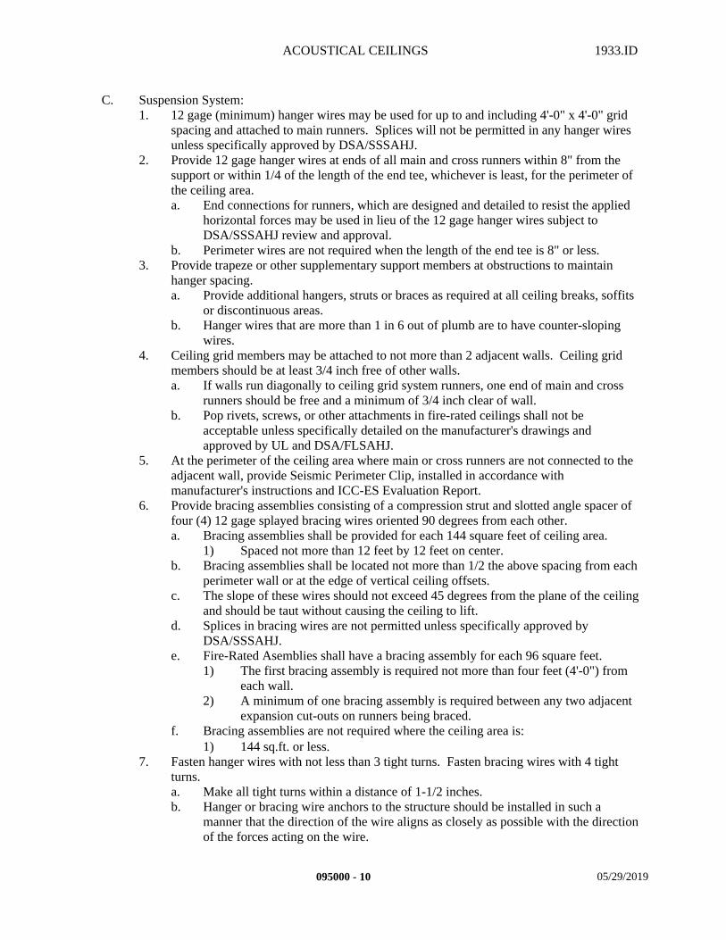
ACOUSTICAL CEILINGS 1933.ID
C. Suspension System:1. 12 gage (minimum) hanger wires may be used for up to and including 4'-0" x 4'-0" grid
spacing and attached to main runners. Splices will not be permitted in any hanger wires unless specifically approved by DSA/SSSAHJ.
2. Provide 12 gage hanger wires at ends of all main and cross runners within 8" from the support or within 1/4 of the length of the end tee, whichever is least, for the perimeter of the ceiling area.a. End connections for runners, which are designed and detailed to resist the applied
horizontal forces may be used in lieu of the 12 gage hanger wires subject to DSA/SSSAHJ review and approval.
b. Perimeter wires are not required when the length of the end tee is 8" or less.3. Provide trapeze or other supplementary support members at obstructions to maintain
hanger spacing.a. Provide additional hangers, struts or braces as required at all ceiling breaks, soffits
or discontinuous areas.b. Hanger wires that are more than 1 in 6 out of plumb are to have counter-sloping
wires.4. Ceiling grid members may be attached to not more than 2 adjacent walls. Ceiling grid
members should be at least 3/4 inch free of other walls.a. If walls run diagonally to ceiling grid system runners, one end of main and cross
runners should be free and a minimum of 3/4 inch clear of wall.b. Pop rivets, screws, or other attachments in fire-rated ceilings shall not be
acceptable unless specifically detailed on the manufacturer's drawings and approved by UL and DSA/FLSAHJ.
5. At the perimeter of the ceiling area where main or cross runners are not connected to the adjacent wall, provide Seismic Perimeter Clip, installed in accordance with manufacturer's instructions and ICC-ES Evaluation Report.
6. Provide bracing assemblies consisting of a compression strut and slotted angle spacer of four (4) 12 gage splayed bracing wires oriented 90 degrees from each other.a. Bracing assemblies shall be provided for each 144 square feet of ceiling area.
1) Spaced not more than 12 feet by 12 feet on center.b. Bracing assemblies shall be located not more than 1/2 the above spacing from each
perimeter wall or at the edge of vertical ceiling offsets.c. The slope of these wires should not exceed 45 degrees from the plane of the ceiling
and should be taut without causing the ceiling to lift.d. Splices in bracing wires are not permitted unless specifically approved by
DSA/SSSAHJ.e. Fire-Rated Asemblies shall have a bracing assembly for each 96 square feet.
1) The first bracing assembly is required not more than four feet (4'-0") from each wall.
2) A minimum of one bracing assembly is required between any two adjacent expansion cut-outs on runners being braced.
f. Bracing assemblies are not required where the ceiling area is:1) 144 sq.ft. or less.
7. Fasten hanger wires with not less than 3 tight turns. Fasten bracing wires with 4 tight turns.a. Make all tight turns within a distance of 1-1/2 inches.b. Hanger or bracing wire anchors to the structure should be installed in such a
manner that the direction of the wire aligns as closely as possible with the direction of the forces acting on the wire.
095000 - 10 05/29/2019
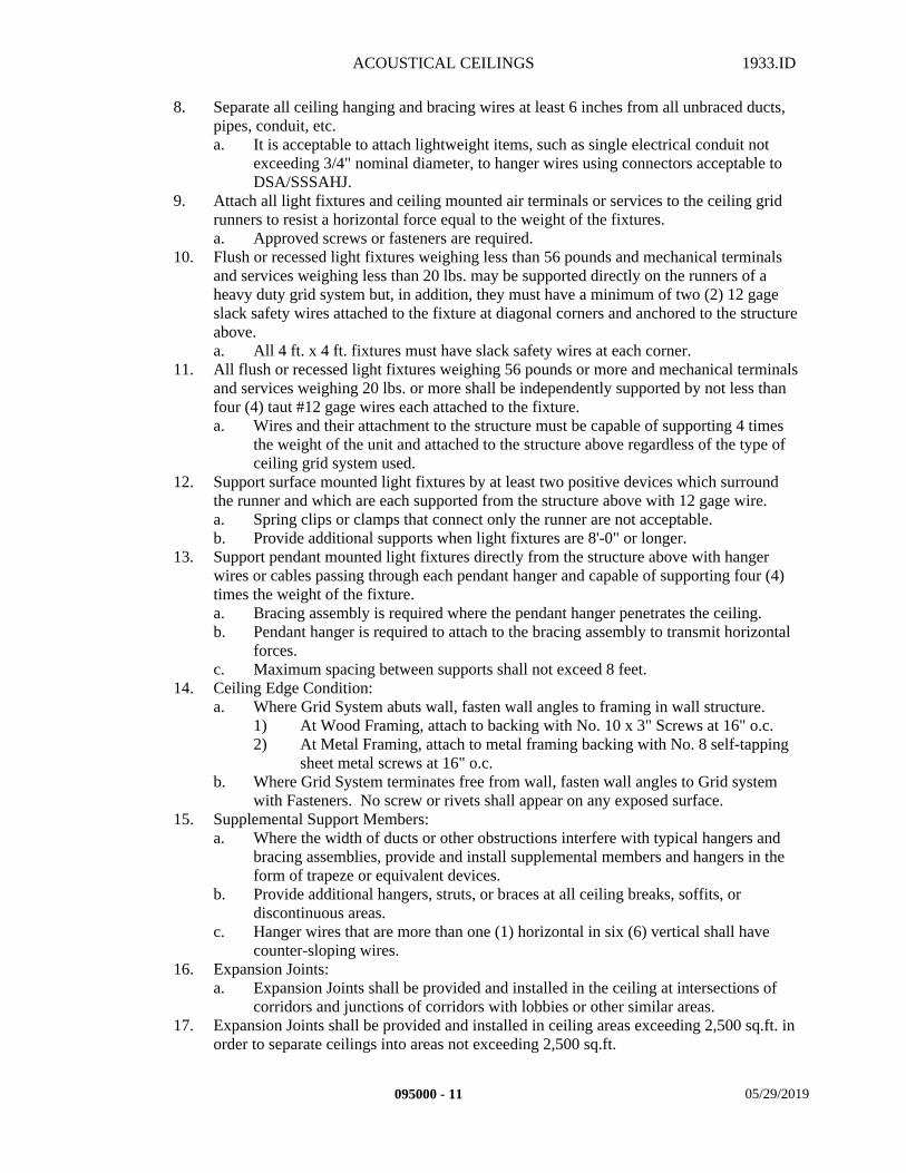
ACOUSTICAL CEILINGS 1933.ID
8. Separate all ceiling hanging and bracing wires at least 6 inches from all unbraced ducts, pipes, conduit, etc.a. It is acceptable to attach lightweight items, such as single electrical conduit not
exceeding 3/4" nominal diameter, to hanger wires using connectors acceptable to DSA/SSSAHJ.
9. Attach all light fixtures and ceiling mounted air terminals or services to the ceiling grid runners to resist a horizontal force equal to the weight of the fixtures.a. Approved screws or fasteners are required.
10. Flush or recessed light fixtures weighing less than 56 pounds and mechanical terminals and services weighing less than 20 lbs. may be supported directly on the runners of a heavy duty grid system but, in addition, they must have a minimum of two (2) 12 gage slack safety wires attached to the fixture at diagonal corners and anchored to the structure above.a. All 4 ft. x 4 ft. fixtures must have slack safety wires at each corner.
11. All flush or recessed light fixtures weighing 56 pounds or more and mechanical terminals and services weighing 20 lbs. or more shall be independently supported by not less than four (4) taut #12 gage wires each attached to the fixture.a. Wires and their attachment to the structure must be capable of supporting 4 times
the weight of the unit and attached to the structure above regardless of the type of ceiling grid system used.
12. Support surface mounted light fixtures by at least two positive devices which surround the runner and which are each supported from the structure above with 12 gage wire.a. Spring clips or clamps that connect only the runner are not acceptable.b. Provide additional supports when light fixtures are 8'-0" or longer.
13. Support pendant mounted light fixtures directly from the structure above with hanger wires or cables passing through each pendant hanger and capable of supporting four (4) times the weight of the fixture.a. Bracing assembly is required where the pendant hanger penetrates the ceiling.b. Pendant hanger is required to attach to the bracing assembly to transmit horizontal
forces.c. Maximum spacing between supports shall not exceed 8 feet.
14. Ceiling Edge Condition:a. Where Grid System abuts wall, fasten wall angles to framing in wall structure.
1) At Wood Framing, attach to backing with No. 10 x 3" Screws at 16" o.c.2) At Metal Framing, attach to metal framing backing with No. 8 self-tapping
sheet metal screws at 16" o.c.b. Where Grid System terminates free from wall, fasten wall angles to Grid system
with Fasteners. No screw or rivets shall appear on any exposed surface.15. Supplemental Support Members:
a. Where the width of ducts or other obstructions interfere with typical hangers and bracing assemblies, provide and install supplemental members and hangers in the form of trapeze or equivalent devices.
b. Provide additional hangers, struts, or braces at all ceiling breaks, soffits, or discontinuous areas.
c. Hanger wires that are more than one (1) horizontal in six (6) vertical shall have counter-sloping wires.
16. Expansion Joints:a. Expansion Joints shall be provided and installed in the ceiling at intersections of
corridors and junctions of corridors with lobbies or other similar areas.17. Expansion Joints shall be provided and installed in ceiling areas exceeding 2,500 sq.ft. in
order to separate ceilings into areas not exceeding 2,500 sq.ft.
095000 - 11 05/29/2019
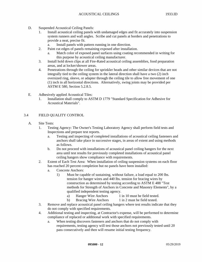
ACOUSTICAL CEILINGS 1933.ID
D. Suspended Acoustical Ceiling Panels:1. Install acoustical ceiling panels with undamaged edges and fit accurately into suspension
system runners and wall angles. Scribe and cut panels at borders and penetrations to provide a neat, precise fit.a. Install panels with pattern running in one direction.
2. Paint cut edges of panels remaining exposed after installation.a. Match color of exposed panel surfaces using coating recommended in writing for
this purpose by acoustical ceiling manufacturer.3. Install hold down clips at all Fire-Rated acoustical ceiling assemblies, food preparation
areas, and at locker/shower areas.4. Penetrations through the ceiling for sprinkler heads and other similar devices that are not
integrally tied to the ceiling system in the lateral direction shall have a two (2) inch oversized ring, sleeve, or adapter through the ceiling tile to allow free movement of one (1) inch in all horizontal directions. Alternatively, swing joints may be provided per ASTM E 580, Section 5.2.8.5.
E. Adhesively applied Acoustical Tiles:1. Installation shall comply to ASTM D 1779 "Standard Specification for Adhesive for
Acoustical Materials".
3.4 FIELD QUALITY CONTROL
A. Site Tests:1. Testing Agency: The Owner's Testing Laboratory Agency shall perform field tests and
Inspections and prepare test reports.a. Testing and inspecting of completed installations of acoustical ceiling fasteners and
anchors shall take place in successive stages, in areas of extent and using methods as follows.
b. Do not proceed with installations of acoustical panel ceiling hangers for the next area until test results for previously completed installations of acoustical panel ceiling hangers show compliance with requirements.
2. Extent of Each Test Area: When installation of ceiling suspension systems on each floor has reached 20 percent completion but no panels have been installed:a. Concrete Anchors:
1) Must be capable of sustaining, without failure, a load equal to 200 lbs. tension for hanger wires and 440 lbs. tension for bracing wires by construction as determined by testing according to ASTM E 488 "Test methods for Strength of Anchors in Concrete and Masonry Elements", by a qualified independent testing agency.a) Hanger Wire Anchors 1 in 10 must be field tested.b) Bracing Wire Anchors 1 in 2 must be field tested.
3. Remove and replace acoustical panel ceiling hangers where test results indicate that they do not comply with specified requirements.
4. Additional testing and inspecting, at Contractor's expense, will be performed to determine compliance of replaced or additional work with specified requirements.a. When testing discovers fasteners and anchors that do not comply with
requirements, testing agency will test those anchors not previously tested until 20 pass consecutively and then will resume initial testing frequency.
095000 - 12 05/29/2019
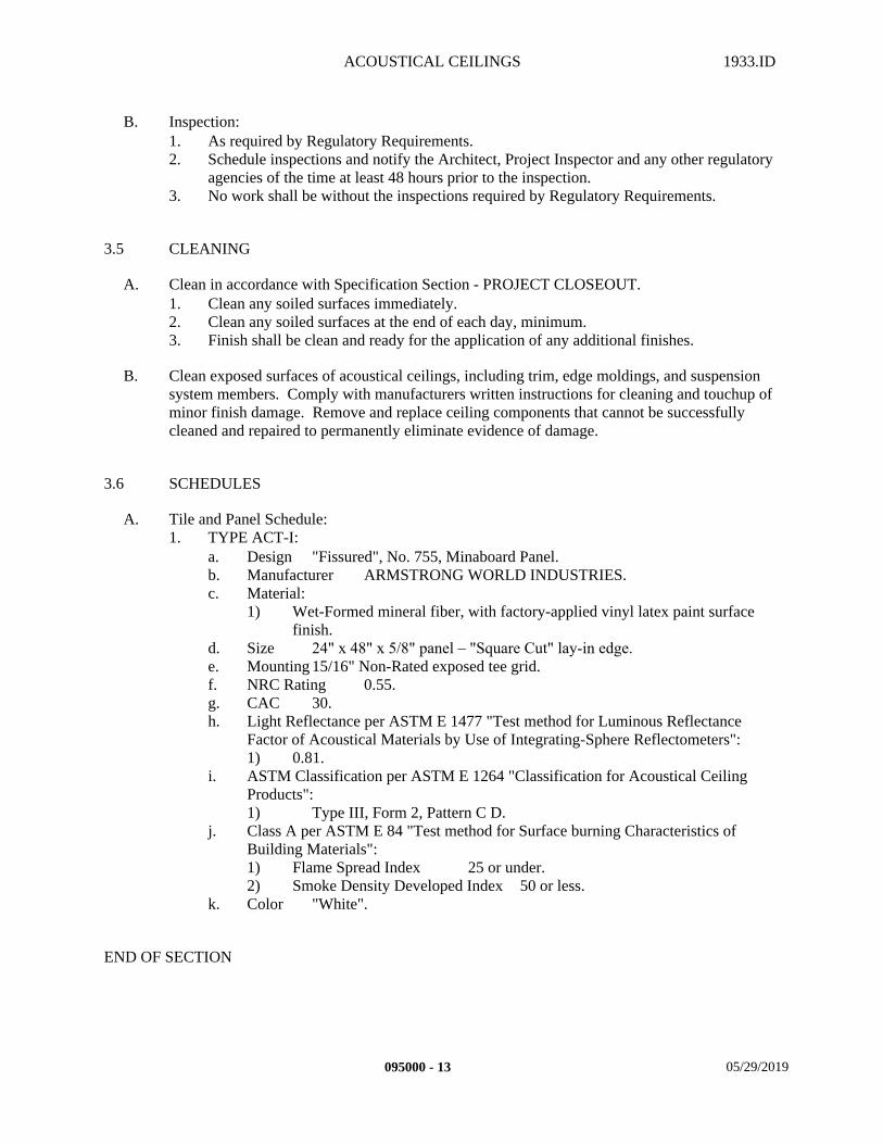
ACOUSTICAL CEILINGS 1933.ID
B. Inspection:1. As required by Regulatory Requirements.2. Schedule inspections and notify the Architect, Project Inspector and any other regulatory
agencies of the time at least 48 hours prior to the inspection.3. No work shall be without the inspections required by Regulatory Requirements.
3.5 CLEANING
A. Clean in accordance with Specification Section - PROJECT CLOSEOUT.1. Clean any soiled surfaces immediately.2. Clean any soiled surfaces at the end of each day, minimum.3. Finish shall be clean and ready for the application of any additional finishes.
B. Clean exposed surfaces of acoustical ceilings, including trim, edge moldings, and suspension system members. Comply with manufacturers written instructions for cleaning and touchup of minor finish damage. Remove and replace ceiling components that cannot be successfully cleaned and repaired to permanently eliminate evidence of damage.
3.6 SCHEDULES
A. Tile and Panel Schedule:1. TYPE ACT-I:
a. Design "Fissured", No. 755, Minaboard Panel.b. Manufacturer ARMSTRONG WORLD INDUSTRIES.c. Material:
1) Wet-Formed mineral fiber, with factory-applied vinyl latex paint surface finish.
d. Size 24" x 48" x 5/8" panel – "Square Cut" lay-in edge.e. Mounting 15/16" Non-Rated exposed tee grid.f. NRC Rating 0.55.g. CAC 30.h. Light Reflectance per ASTM E 1477 "Test method for Luminous Reflectance
Factor of Acoustical Materials by Use of Integrating-Sphere Reflectometers":1) 0.81.
i. ASTM Classification per ASTM E 1264 "Classification for Acoustical Ceiling Products":1) Type III, Form 2, Pattern C D.
j. Class A per ASTM E 84 "Test method for Surface burning Characteristics of Building Materials":1) Flame Spread Index 25 or under.2) Smoke Density Developed Index 50 or less.
k. Color "White".
END OF SECTION
095000 - 13 05/29/2019

RESILIENT BASE AND ACCESSORIES 1933.ID
SECTION 096510 – RESILIENT BASE AND ACCESSORIES
PART 1 - GENERAL
1.1 SUMMARY
A. This Section includes the following:1. Provide all material, labor, equipment and services necessary to completely install all
Resilient Base and Accessories and other related items necessary to complete the Project as indicated by the Contract Documents.
B. Related Sections: The following Project Manual Sections contain requirements that relate to this section:1. ALL DIVISION 00 SPECIFICATION SECTIONS.2. ALL DIVISION 01 SPECIFICATION SECTIONS.3. 03 30 00 CAST-IN-PLACE CONCRETE4. 06 10 00 ROUGH CARPENTRY5. 06 41 23 MODULAR CASEWORK6. 09 29 00 GYPSUM BOARD7. 09 56 19 RESILIENT TILE8. 09 91 00 PAINTING9. 10 05 00 MISCELLANEOUS SPECIALTIES10. ALL SPECIFICATION SECTIONS IN THE FACILITY SERVICES SUBGROUP.
1.2 REFERENCES
A. Standards:1. In accordance with Specification Section - Regulatory Requirements, and the following
standards:a. ADAAG Americans with Disabilities Act Accessibilities Guidelines. b. RFCI The Resilient Floor Covering Institute.
1.3 SUBMITTALS
A. Submit in accordance with Specification Section - SUBMITTAL PROCEDURES:1. Product Data:
a. For each type of resilient base and accessory indicated.b. Manufacturer's full color range (including any standard and premium colors).c. Design Data for all compounds, fillers, adhesives, etc.
2. Samples.a. Provide 6 inch linear samples of each piece of trim material specified.
3. Quality Assurance/Control Submittals:a. Manufacturer's Written Installation Instructions.b. Certificate from resilient base installer that all products supplied for installation
comply with local CARB regulations in the area where the project is located controlling the use of Volatile Organic Compounds (VOC's).
096510 - 1 05/29/2019
RESILIENT BASE AND ACCESSORIES 1933.ID
c. Statement of Installer’s Qualifications.4. Closeout Submittals in accordance with Specification Sections in Division One:
a. Maintenance Data (including recommended polish and buffing procedures) in accordance with Specification Section - PROJECT CLOSEOUT.
b. Record Documents in accordance with Specification Section – PROJECT DOCUMENTS.
c. Warranty in accordance with this Specification Section, and Specification Section – WARRANTIES.
1.4 QUALITY ASSURANCE
A. Qualifications:1. Installer Qualifications:
a. Engage an experienced Installer who has successfully completed three (3) projects of similar scope and size to that indicated for this Project, and is competent in the techniques required by the manufacturer.
2. Manufacturer/Supplier Qualifications:a. Firm experienced in successfully producing/supplying products similar to that
indicated for this Project, with sufficient production/supply capacity to produce/supply required units without causing delay in the work.
B. Regulatory Requirements:1. CARB Materials and equipment used for this Project shall comply with the current
applicable regulations of the California Air Resources Board (CARB) and the Environmental Protection Agency (EPA) in the area where the project is located.
2. CBC California Building Code (CBC 804.1)
C. Meetings:1. Pre-Installation: Scheduled by the Contractor prior to the start of work.
a. Coordinate the work with other work being performed.b. Identify any potential problems that may impede planned progress and proper
installation of work regarding quality of installation and warranty requirements. c. Review delivery, storage, and handling procedures.d. Review Project Conditions.e. Review subfloor preparation procedures.
2. Progress: Scheduled by the Contractor during the performance of the work.a. Review for proper installation of work progress.b. Identify any installation problems and acceptable corrective measures.c. Identify any measures to maintain or regain project schedule if necessary.
3. Completion: Scheduled by the Contractor upon proper completion of the work.a. Inspect and identify any problems that may impede issuance of warranties or
guaranties.b. Maintain installed work until the Notice of Substantial Completion has been
executed.
1.5 DELIVERY, STORAGE, AND HANDLING
A. Packing, shipping, handling, and unloading:
096510 - 2 05/29/2019
RESILIENT BASE AND ACCESSORIES 1933.ID
1. Products shall be handled in such a manner as to assure that they are free from dents, scratches and other damage.
B. Acceptance at Site:1. Products must be in manufacturer's original unopened containers with labels indicating
brand name, type, color, and size.2. Damaged products will not be accepted.
C. Storage and protection:1. Products shall be stored in a dry, protected, interior area above ground on level platforms,
six (6) inches above ground, allowing air circulation under stacked units.a. Cover materials with protective waterproof covering providing for adequate air
circulation and ventilation.b. Maintain temperature in the storage space between fifty (50) degrees Fahrenheit
and ninety (90) degrees Fahrenheit.1) Seven (7) days prior to installation, acclimate products to environmental
requirements of the article titled PROJECT CONDITIONS of this specification section, and the Paragraph titled "Environmental Requirements".
1.6 PROJECT CONDITIONS
A. Environmental requirements:1. Temperature: Maintain temperature in space to receive products at sixty-eight (68)
degrees Fahrenheit for two (2) days prior, during, and two (2) days following installation.a. After this period, maintain a temperature of not less than fifty-five (55) degrees
Fahrenheit.b. After installation, at no such time shall the temperature exceed eighty-five (85)
degrees Fahrenheit.
B. Existing Conditions:1. Examine site and compare it with the drawings and specifications. Thoroughly
investigate and verify conditions under which the work is to be performed. No allowance will be made for extra work resulting from negligence or failure to be acquainted with all available information concerning conditions necessary to estimate the difficulty or cost of the work.
2. Field Measurements:a. Take and be responsible for field measurements as required.b. Report any significant differences between field dimensions and drawings to the
Architect.
1.7 WARRANTY
A. Contractor’s General Warranty:1. In accordance with Specification Section - WARRANTIES.
B. Manufacturer's Warranty:1. In accordance with manufacturer's written standard warranty:
a. Rubber Base Two (2) Years.
096510 - 3 05/29/2019
RESILIENT BASE AND ACCESSORIES 1933.ID
b. Transitions Two (2) years.
C. Installer's Warranty:1. In accordance with the terms of the Specification Section - WARRANTIES:
a. Warranty Period Two (2) Years.
PART 2 - PRODUCTS
2.1 MANUFACTURERS
A. These products listed herein establish the size, pattern, color range and function selected by the Architect for this Project. Manufacturers that are listed as acceptable alternative manufacturers and substitutions must still comply with the requirements of this project and the products listed in order to be approved as an equivalent during the Submittal Process. If the acceptable alternative manufacturers listed or substitutions are not approved during the Submittal Process due to non-compliance with the contract documents, then the Contractor shall submit product specified. 1. Rubber Base manufacturer:
a. BURKE FLOORING.2. Transitions manufacturer:
a. BURKE FLOORING.b. Acceptable alternative manufacturers:
1) ROPPE CORPORATION.3. Underlayment Compound manufacturer:
a. ARDEX INCORPORATED.b. Acceptable alternative manufacturers:
1) CHEMREX.a) A compatible bonding agent is needed for this product to adhere to the
Vapor-Alkalinity Control System and be considered as equivalent.4. Crack and Joint Filler manufacturer:
a. ARDEX INCORPORATED.
B. Products from other manufacturers not listed must submit in accordance with Specification Section - SUBSTITUTION PROCEDURES.
2.2 MATERIALS
A. General:1. Resilient base and accessories shall be of first quality and the product of one
manufacturer.2. Colors and patterns shall be selected from manufacturer's standard line (including
premium) except as noted otherwise.a. Stair treads, risers, and stringers shall be of the same color or matching color and
product line.3. All resilient base and accessories shall be impervious to water damage.
B. Rubber Base:
096510 - 4 05/29/2019
RESILIENT BASE AND ACCESSORIES 1933.ID
1. Shall comply with ASTM F 1861 "Standard Specification for Resilient Wall Base", for Type TS (Vulcanized Rubber), Group 1 (Solid and Homogeneous).a. Critical Radiant Flux shall be Class 1, not less than 0.45 W/sq.cm. per ASTM E
648 "Test Method for Critical Radiant Flux of Floor Covering Systems Using a Radiant Heat Energy Source".
2. Base shall be Coved.3. Base height shall be 4".4. Thickness shall be 0.125".5. Provide pre-formed inside and outside base corners from the same dye lot as the rubber
base.
C. Transitions:1. Include molding caps, dividers, edges, cove supports, feature strips, reducers, stair
nosings, etc.2. Shall be composed of Thermoplastic Vinyl throughout item.3. Critical Radiant Flux shall be Class 1, not less than 0.45 W/sq.cm. per ASTM E 648
"Test Method for Critical Radiant Flux of Floor Covering Systems Using a Radiant Heat Energy Source".
4. Shall comply to dimension requirements of section 4.5.2 (changes in level) and section 4.5.3 (carpet-edge trim) of the ADAAG.
2.3 ACCESSORIES
A. Underlayment Compound:1. Provide free-flowing, self-leveling, pumpable, cement based compound (ARDEX K-15)
for applications from 1 inch thick to feathered edges, 4000 psi minimum in accordance with ASTM C 109-modified for air cure only "Test Method for Compressive Strength of Hydraulic Cement Mortars (Using 2-in. Cube Specimens)".a. ARDEX "K-15".
B. Crack and Joint Filler:1. Provide low viscosity rigid polyurethane filler, tensile strength of 4,000 psi minimum, in
accordance with ASTM D 638 "Test method for Tensile Properties of Plastics".a. ARDEX "ARDIFIX".
C. Concrete Primer (if applicable):1. Nonstaining type as recommended in writing by flooring manufacturer.
D. Adhesives:1. Adhesive as recommended in writing by resilient base manufacturer.
a. Provide manufacturer's written recommended epoxy adhesive at all rubber stair accessories and rubber stair nosings.
2. Compatible with Vapor-Alkalinity Control System, if installed.3. Shall comply with CARB requirements in the place where the project is located.4. Shall be water and mildew resistant.5. Shall bond to non-porous substrate surfaces.
096510 - 5 05/29/2019
RESILIENT BASE AND ACCESSORIES 1933.ID
PART 3 - EXECUTION
3.1 EXAMINATION
A. Site verification of conditions:1. Prior to the execution of the work under this specification section, inspect the installed
work executed under other sections of this Project Manual that affect the execution of work under this specification section.
2. Insure that all flooring has been installed, fitted close to the wall to provide even support to the resilient base, and to insure a tight, smooth fit along the floor.
3. Report unacceptable conditions to the Architect. Do not begin work until unacceptable conditions have been corrected.
4. Execution of work under this specification section shall constitute acceptance of existing conditions.
B. Concrete Subfloors: 1. Verify that concrete slabs comply with ASTMF 710 "Practice for Preparing Concrete
Floors to Receive Resilient Flooring".2. Verify that substrates are dry and free of curing compounds, sealers, hardeners, and other
materials that may interfere with adhesive bond.3. Verify that subfloors are free of cracks, ridges, depressions, scale, and foreign deposits.4. Evaluate the RH (Relative Humidity) and pH (Alkalinity) for compliance with adhesives
and resilient tile manufacturer's written substrate preparation recommendations.a. If a Vapor-Alkalinity Control System product has been installed to reduce water
vapor emission or phosphates thereby negating the RH and pH Test Results, evaluate products for compatibility with adhesives and resilient base products.
5. Determine adhesion characteristics by performing bond tests recommended by the resilient base and accessory manufacturer.
3.2 PREPARATION
A. Coordination:1. Coordinate work under this specification section with work specified under other sections
to ensure proper and adequate interface of work.
B. Protection:1. Protect all adjacent surfaces from drips, spray, air pollution of surrounding environment,
and other damage from work.
C. Surface preparation:1. Prepare surface in accordance with manufacturer's written instructions and
recommendations.2. Wall substrates to receive resilient base must be completely clean, dry, smooth and free
of oil, grease, rust, paint, varnish, shellac, or any other foreign substance.
096510 - 6 05/29/2019
RESILIENT BASE AND ACCESSORIES 1933.ID
3. From floor substrates, remove coatings, including curing compounds, and other substances that are incompatible with adhesives and that may contain soap, wax, oil, or silicone, without using solvents. Use mechanical methods recommended in writing by the resilient base and accessory manufacturer.a. If a Vapor-Alkalinity Control System has been installed, do not remove this
system.4. Fill all cracks, joints, etc. with a Crack and Joint Filler according to manufacturer's
written instructions.5. Install self-leveling underlayment compound at depressed or uneven floor conditions.6. Vacuum clean substrates to be covered immediately before installation.7. After cleaning, examine substrates for moisture, alkaline salts, carbonation, or dust.8. Proceed only after unsatisfactory conditions have been corrected.9. Perform manufacturer recommended bond test to verify adhesion of resilient base and
accessory to substrate.10. Apply any recommended primers over the leveling compounds or treated concrete slabs
prior to the installation of any resilient base or accessory products if recommended by the manufacturer.
3.3 INSTALLATION
A. General:1. In accordance with manufacturer's written instructions and recommendations unless
specifically noted otherwise.2. In accordance with approved submittals.3. In accordance with Regulatory Requirements.4. Set plumb, level, and square.
B. Layout:1. Lines shall be straight and true.2. Refer to Floor Pattern Drawing(s) in the Interior Color Schedule for transitions in color.
C. Resilient Base installation:1. For base installations on primed metal or enameled surfaces, provide manufacturer's
written recommended co-adhesive method of installation applied to both surfaces with contact bond adhesive.
2. On dry, absorbent surfaces, the base shall be adhered with manufacturer's written recommended adhesive and firmly pressed to the walls.
3. Apply resilient base to walls, columns, pilasters, casework and cabinets in toe spaces, and other permanent fixtures in rooms and areas where base is required.
4. Install resilient base in lengths as long as practicable without gaps at seams and with tops of adjacent pieces aligned.
5. Tightly adhere resilient base to substrate throughout length of piece, with base in continuous contact with horizontal and vertical substrates.
6. Do not stretch resilient base during installation.7. On masonry surfaces, or other similar irregular substrates, fill voids along top edge of
resilient base with manufacturer’s recommended adhesive filler material.8. Pre-molded Corners: Install pre-molded corners before installing straight pieces.9. After the installation, remove all excess adhesive before it dries.10. Allow adhesive to set firm for approximately 24 hours before washing or applying any
pressure.
096510 - 7 05/29/2019
RESILIENT BASE AND ACCESSORIES 1933.ID
D. Transition installation:1. Measure and trim to fit transition pieces prior to installing.2. Use appropriate approved manufacturer written adhesives for each substrate.3. After installation, immediately remove all excess adhesive before it dries.
3.4 CLEANING
A. Cleaning:1. Clean in accordance with Specification Section - PROJECT CLOSEOUT.2. Clean any soiled surfaces immediately.3. Clean any soiled surfaces at the end of each day, minimum.4. Finish shall be clean and ready for the application of any additional finishes.5. In accordance with manufacturer’s written instructions and recommendations.
3.5 PROTECTION
A. Protection from traffic:1. Provide final protection and maintain conditions, in a manner acceptable to manufacturer
and installer, which ensures the work of this section being without damage or deterioration until the time of Substantial Completion.
END OF SECTION
096510 - 8 05/29/2019
RESILIENT TILE 1933.ID
SECTION 096519 – RESILIENT TILE
PART 1 - GENERAL
1.1 SUMMARY
A. This Section includes the following:1. Provide all material, labor, equipment and services necessary to completely install all
Resilient Tile Floor Covering materials, accessories and other related items necessary to complete the Project as indicated by the Contract Documents.
B. Related Sections: The following Project Manual Sections contain requirements that relate to this section:1. ALL DIVISION 00 SPECIFICATION SECTIONS.2. ALL DIVISION 01 SPECIFICATION SECTIONS.3. 03 30 00 CAST-IN-PLACE CONCRETE4. 06 10 00 ROUGH CARPENTRY5. 06 41 23 MODULAR CASEWORK6. 09 29 00 GYPSUM BOARD7. 09 65 10 RESILIENT BASE AND ACCESSORIES8. 10 05 00 MISCELLANEOUS SPECIALTIES9. ALL SPECIFICATION SECTIONS IN THE FACILITY SERVICES SUBGROUP.
1.2 REFERENCES
A. Standards:1. In accordance with the following standards:
a. ADAAG Americans with Disabilities Act Accessibilities Guidelines b. ASTM American Society of Testing Materialsc. RFCI The Resilient Floor Covering Institute.
1.3 SUBMITTALS
A. Submit in accordance with Specification Section - SUBMITTAL PROCEDURES:1. Product Data.
a. For each type of resilient tile flooring indicated. b. Manufacturer's full color range (including any standard and premium colors).c. Design Data for all components, fillers, adhesives, etc.
2. Samples.a. Provide 12 inch square sample of each color and pattern selected.
3. Quality Assurance/Control Submittals:a. Manufacturer's Written Installation Instructions. b. Certificates:
096519 - 1 05/29/2019
RESILIENT TILE 1933.ID
1) Certificate from floor covering installer that all products supplied for installation comply with local CARB regulations in the area where the project is located controlling the use of Volatile Organic Compounds (VOC's).
c. Statement of Installer's Qualifications.4. Closeout Submittals in accordance with the following:
a. Maintenance Data in accordance with Specification Section - PROJECT CLOSEOUT.
b. Record Documents in accordance with Specification Section - PROJECT DOCUMENTS.
c. Warranty in accordance with this specification and Specification Section - WARRANTIES.
1.4 QUALITY ASSURANCE
A. Qualifications:1. Installer Qualifications:
a. Engage an experienced Installer who has successfully completed three (3) projects of similar scope and size to that indicated for this Project and is competent in techniques required by the manufacturer.
2. Manufacturer/Supplier Qualifications:a. Firm experienced in successfully producing/supplying products similar to that
indicated for this Project, with sufficient production/supply capacity to produce/supply required units without causing delay in the work.
B. Regulatory Requirements:1. In accordance with Specification Section - REGULATORY REQUIREMENTS, and the
following:a. CARB Materials and equipment used for this Project shall comply with the
current applicable regulations of the California Air Resources Board (CARB) and the Environmental Protection Agency (EPA), in the area where the project is located.
b. CBC California Building Code (CBC 804.1)
C. Meetings:1. Pre-Installation: Scheduled by the Contractor prior to the start of work.
a. Coordinate the work with other work being performed.b. Identify any potential problems that may impede planned progress and proper
installation of work regarding quality of installation and warranty requirements.c. Review delivery, storage, and handling procedures.d. Review the article titled PROJECT CONDITIONS of this specification section.e. Review subfloor preparation procedures.
2. Progress: Scheduled by the Contractor during the performance of the work.a. Review for proper installation of work progress.b. Identify any installation problems and accfeptable corrective measures.c. Identify any measures to maintain or regain project schedule if necessary.
3. Completion: Scheduled by the Contractor upon proper completion of the work.a. Inspect and identify any ptoblems that may impede issuance of warranties or
guaranties.
096519 - 2 05/29/2019
RESILIENT TILE 1933.ID
b. Maintain installed work until the Notice of Substantial Completion has been executed.
1.5 DELIVERY, STORAGE, AND HANDLING
A. Packing, shipping, handling, and unloading: 1. Products shall be handled in such a manner as to assure that they are free from dents,
scratches and other damage.
B. Acceptance at Site: 1. Products must be in manufacturer's original unopened containers with labels indicating
brand name, model, and grade. 2. Damaged products will not be accepted.
C. Storage and protection: 1. Products shall be stored in a dry, protected, interior area above ground on level platforms,
six (6) inches above ground, allowing air circulation under stacked units. a. Cover materials with protective waterproof covering providing for adequate air
circulation and ventilation.b. Maintain temperature in the storage space between fifty (50) degrees Fahrenheit
and ninety (90) degrees Fahrenheit.1) Seven (7) days prior to installation, acclimate products to environmental
requirements of the article titled PROJECT CONDITIONS of this specification section, and the Paragraph titled “Environmental Requirements”.
c. Do not double stack.
1.6 PROJECT CONDITIONS
A. Environmental requirements:1. Temperature: Maintain ambient temperature in space to receive products at sixty-eight
(68) degrees Fahrenheit for two (2) days prior, during, and two (2) days minimum following installation.a. After this period, maintain a temperature of not less than 55 degrees Fahrenheit.b. After installation, at no such time shall the temperature exceed 85 degrees
Fahrenheit.c. Inform the Owner of ambient temperature requirements for products installed and
maintain until Substantial Completion and turn-over of the building or facility to the Owner.
B. Existing Conditions: 1. Examine site and compare it with the drawings and specifications. Thoroughly
investigate and verify conditions under which the work is to be performed. No allowance will be made for extra work resulting from negligence or failure to be acquainted with all available information concerning conditions necessary to estimate the difficulty or cost of the work.
2. Field Measurements:a. Take and be responsible for field measurements as required.
096519 - 3 05/29/2019
RESILIENT TILE 1933.ID
b. Report any significant differences between field dimensions and drawings to the Architect.
1.7 WARRANTY
A. Contractor's General Warranty:1. In accordance with Specification Section - WARRANTIES.
B. Manufacturer's Warranty:1. In accordance with manufacturer's written standard warranty:
a. Luxury Vinyl Plank Ten (10) Years.
C. Installer's Warranty:1. In accordance with the terms of the specification section - WARRANTIES:2. Warranty period Five (5) years.
1.8 MAINTENANCE
A. Extra Materials:1. Furnish not less than one box for each 50 boxes or fraction thereof, of each class, wearing
surface, color, pattern and size of resilient floor tile installed.
PART 2 - PRODUCTS
2.1 MANUFACTURERS
A. These products listed herein establish the size, pattern, color range and function selected by the Architect for this Project. Manufacturers that are listed as acceptable alternative manufacturers and substitutions must still comply with the requirements of this project and the products listed in order to be approved as an equivalent during the Submittal Process. If the acceptable alternative manufacturers listed or substitutions are not approved during the Submittal Process due to non-compliance with the contract documents, then the Contractor shall submit product specified. 1. Luxury Vinyl PLank manufacturer:
a. MOHAWK.2. Underlayment Compound:
a. ARDEX INCORPORATED.b. Acceptable alternative manufacturers:
1) CHEMREXa) A compatible bonding agent is needed for this product to adhere to the
Vapor-Alkalinity Control System and be considered as equivalent.3. Crack and Joint Filler manufacturer:
a. ARDEX INCORPORATED.
B. Products from other manufacturers not listed must submit in accordance with Specification Section - SUBSTITUTION PROCEDURES.
096519 - 4 05/29/2019
RESILIENT TILE 1933.ID
2.2 MATERIALS
A. General:1. Resilient Tile Flooring shall be the product of one manufacturer and shall to the
maximum extent possible be of a single lot number.2. Resilient Tile Flooring shall be slip resistant by achieving a minimum 0.6 or greater static
coefficient of friction as recommended in Appendix A4.5 of the ADAAG by testing per ASTM D 2047 "Test method for Static Coefficient of Friction of Polish-Coated Flooring Surfaces as Measured by the James Machine".a. Resilient Tile Flooring installed on ramps shall achieve a minimum 0.8 or greater
static coefficient of friction as recommended in Appendix A4.5 of the ADAAG by testing per ASTM D 2047 "Test method for Static Coefficient of Friction of Polish-Coated Flooring Surfaces as Measured by the James Machine".
3. Colors and patterns shall be selected from manufacturer's standard line (including premium) except as noted otherwise.
4. All Resilient Tile Flooring shall be impervious to water damage.
B. Luxury Vinyl Plank:1. Shall comply with ASTM F 1700 "Specification for Solid Vinyl Floor Tile".
2.3 ACCESSORIES
A. Underlayment Compound:1. Provide free-flowing, self-leveling, pumpable, cement based compound for applications
from 1 inch thick to feathered edges, 4000 psi minimum in accordance with ASTM C 109 "Test Method for Compressive Strength of Hydraulic Cement Mortars (Using 2-in. Cube Specimens)", modified for air cure only.a. ARDEX "K-15".
B. Crack and Joint Filler:1. Provide low viscosity rigid polyurethane filler, tensile strength of 4,000 psi minimum, in
accordance with ASTM D 638 "Test method for Tensile Properties of Plastics".a. ARDEX "ARDIFIX".
C. Concrete Primer (if applicable):1. Nonstaining type as recommended in writing by flooring manufacturer.
D. Adhesives:1. Adhesive as recommended in writing by resilient tile manufacturer.2. Compatible with Vapor-Alkalinity Control System, if installed.3. Shall comply with CARB requirements in the place where the project is located.4. Shall be water and mildew resistant.5. Shall bond to non-porous substrate surfaces.
096519 - 5 05/29/2019
RESILIENT TILE 1933.ID
PART 3 - EXECUTION
3.1 EXAMINATION
A. Site verification of conditions:1. Prior to the execution of the work under this specification section, inspect the installed
work executed under other sections of this Project Manual which, affect the execution of work under this specification section.
2. Check sub-floor variation with long straight edge.3. Report unacceptable conditions to the Architect. Do not begin work until unacceptable
conditions have been corrected.4. Execution of work under this specification section shall constitute acceptance of existing
conditions.
B. Concrete Subfloors: 1. Verify that concrete slabs comply with ASTM F 710 "Practice for Preparing Concrete
Floors to Receive Resilient Flooring".2. Verify that substrates are dry and free of curing compounds, sealers, hardeners, and other
materials that may interfere with adhesive bond.3. Verify that subfloors are free of cracks, ridges, depressions, scale, and foreign deposits.4. Evaluate the RH (Relative Humidity) and pH (Alkalinity) test results for compliance with
adhesives and resilient tile manufacturer's written substrate preparation recommendations.a. If a Vapor-Alkalinity Control System product has been installed to reduce water
vapor emission or phosphates thereby negating the RH and pH Test Results, evaluate products for compatibility with adhesives and resilient tile products.
5. Determine adhesion characteristics by performing bond tests recommended by the resilient tile manufacturer.
3.2 PREPARATION
A. Coordination:1. Coordinate work under this specification section with work specified under other sections
to ensure proper and adequate interface of work.
B. Protection:1. Protect all adjacent surfaces from drips, spray, air pollution of surrounding environment,
and other damage from work.
C. Surface preparation:1. Prepare surface in accordance with manufacturer's written instructions and
recommendations.2. Remove coatings, including curing compounds, and other substances that are
incompatible with adhesives and that may contain soap, wax, oil, or silicone, without using solvents. Use mechanical methods recommended in writing by the resilient tile manufacturer.
096519 - 6 05/29/2019
RESILIENT TILE 1933.ID
a. If a Vapor-Alkalinity Control System has been installed, do not remove this system.
3. Fill all cracks, joints, etc. with a Crack and Joint filler according to manufacturer's written instructions.
4. Install self-leveling underlayment compound at depressed or uneven floor conditions.5. Broom and vacuum clean substrates to be covered immediately before installing resilient
tile.6. After cleaning, examine substrates for moisture, alkaline salts, carbonation, or dust.7. Proceed with installation only after unsatisfactory conditions have been corrected.8. Apply any recommended primers over the leveling compounds or treated concrete slabs
prior to the installation of any resilient tile products.9. Concrete (Previous Flooring Material Removed): Remove existing adhesive by grinding
with a concrete grinding machine and moist sand. Do not use solvents to remove adhesive.
3.3 INSTALLATION
A. General:1. In accordance with manufacturer's written instructions and recommendations unless
specifically noted otherwise.2. In accordance with approved submittals. 3. In accordance with Regulatory Requirements.
B. Layout:1. Lines shall be straight and true.2. Refer to Floor Pattern Drawing(s) in the Interior Color Schedule for layout of patterns.
C. Resilient Tile installation:1. Apply adhesive in accordance with manufacturer's current written recommendations.
a. Do not apply adhesive too far in advance of the tile installation. Adhesive must be sufficiently "tacky" in accordance with adhesive manufacturer's written recommendations for the proper installation of the tile.
2. Start installation at center line of room, unless indicated otherwise, and work towards the borders.
3. Border tiles shall not be less than half a tile.4. Scribe, cut, and fit resilient tile flooring to butt tightly to vertical surfaces, permanent
fixtures, and built-in furniture, including cabinets, pipes, outlets, edgings, thresholds, and nosing’s.
5. Extend resilient tile flooring into toe spaces, door reveals, closets, and similar openings.6. Installation shall be true, level, and even with tight joints.7. Check work to see that all tile are lying down and setting in.8. Maintain reference markers, holes or openings that are in place or plainly marked for
future cutting by repeating on finish flooring as marked on subfloor. Use chalk or other non-permanent marking device.
3.4 CLEANING
A. Cleaning:1. Clean in accordance with Specification Section - PROJECT CLOSEOUT.
096519 - 7 05/29/2019
RESILIENT TILE 1933.ID
2. Clean any soiled surfaces immediately.3. Clean any soiled surfaces at the end of each day, minimum.4. Finish shall be clean and ready for the application of any additional finishes.5. In accordance with manufacturer's written instructions and recommendations.
3.5 DEMONSTRATION
A. In accordance with Specification Section – PROJECT CLOSEOUT.1. Provide the services of a manufacturer-authorized service representative to demonstrate
and train Owner’s maintenance personnel as specified below.a. Train Owner’s maintenance personnel on cleaning procedures and schedules
related to cleaning and preventative maintenance,b. Schedule training with the Owner’s maintenance personnel with at least seven (7)
days advance notice.
3.6 PROTECTION
A. Protection from traffic: 1. Provide final protection and maintain conditions, in a manner acceptable to manufacturer
and installer, which ensures the work of this section being without damage or deterioration until the time of Substantial Completion.
3.7 SCHEDULES
A. Luxury Vinyl Plank.1. Manufacturer: MOHAWK.2. Product Name: Antiek.3. Physical Characteristics:
a. Wearing Surface: Wood Emboss/Embossed-In-Register.b. Classification of Composition per ASTM F 1700 “Specification for Solid Vinyl
Floor Tile”:1) Class III, Type A - Smooth. Type B Embossed..
c. Overall Thickness: +/- 0.005..d. Tile Size: 8" W x 60" L.e. Static Load Limit per ASTM F 970 “Test method for Static Load Limit”:
1) 1500 psi.4. Performance Characteristics:
a. Critical Radiant Flux per ASTM E 648 “Test Method for Critical Radiant Flux of Floor-Covering Systems Using a Radiant Heat Energy Source”:1) Class 1, not less than 0.45 W/sq.cm.
b. Smoke Density per ASTM E 662 “Test method for Specific Optical Density of Smoke Generated by Solid Materials”:1) Less than 450.
END OF SECTION
096519 - 8 05/29/2019
PAINTING 1933.ID
SECTION 099100 - PAINTING
PART 1 - GENERAL
1.1 SUMMARY
A. This Section includes the following:1. Provide all material, labor, equipment and services necessary to furnish and install
Painting, accessories and other related items necessary to complete the Project as indicated by the Contract Documents unless specifically excluded.a. Material and Equipment to be Painted: Paint all piping, unwrapped ductwork,
electric conduits exposed to view. Prime and paint all factory finished mechanical and electrical equipment and accessories exposed to view.
b. Material and Equipment not to be Painted: Do not paint piping, ductwork, equipment and machinery located in attic spaces, above furred or suspended ceilings, in furred pipe or duct spaces. Do not paint factory finished equipment or machinery located in mechanical rooms or mechanical buildings, attics, furred or suspended ceilings.
B. Related Sections: The following Project Manual Sections contain requirements that relate to this section:1. ALL DIVISION 00 SPECIFICATION SECTIONS.2. ALL DIVISION 01 SPECIFICATION SECTIONS.3. 05 12 00 STEEL AND FABRICATIONS4. 06 41 23 MODULAR CASEWORK5. 08 14 16 WOOD DOORS6. 08 80 00 GLASS7. 09 29 00 GYPSUM BOARD8. 09 50 00 ACOUSTICAL CEILINGS9. 09 65 10 RESILIENT BASE AND ACCESSORIES10. 10 05 00 MISCELLANEOUS SPECIALTIES11. ALL SPECIFICATION SECTIONS IN THE FACILITY SERVICES SUBGROUP.
1.2 REFERENCES
A. Standards:1. In accordance with the following standards:
a. CA-CHPS California High Performance Schools1) 2011-CA-CHPS Addendum.
b. MPI Master Painters Institute 1) MPI - Architectural Painting Specification Manual. 2) MPI – Maintenance Repainting Manual.
a) MPI RSP Master Painters Institute Repaint Surface Preparation Standards, Chapter 6, Section 2.
3) MPI – Glossary.
099100 - 1 05/28/2019
PAINTING 1933.ID
c. PDCA Painting and Decorating Contractors of America, latest edition of the Architectural Specification Manual, as prepared by Specification Services, Inc., Washington State Council of the PDCA.
1.3 DEFINITIONS
A. The following definitions are just some of the more important definitions used within this section, and were taken from the MPI Glossary Manual, or used to simplify language used by the Architect. These definitions and others stated within the Manual apply for this Specification Section.1. Acrylic Latex An aqueous dispersion of acrylic resins.2. Acrylic Resin A/R - Synthetic resins made by polymerizing esters of acrylic acid.3. A/U Aliphatic Urethane 4. A/A/U Aliphatic Acrylic Urethane5. Blocking Sticking or bonding together of two painted surfaces that are in direct
contact. Most often caused by stacking painted articles before dry or reaching a "block free" (or "non-blocking") stage.
6. DFT Dry Film Thickness – the depth or thickness of a coating in the dry state. Expressed in mils (1/1000 inch) or microns.
7. DRY FALL A Fog Paint designed to be applied by spray and dries fast enough that the overspray will be a dry powder after falling a certain distance. The dust can then be swept or vacuumed up.
8. ODFT "Overall Dry Film Thickness" – the depth or thickness of a complete coating system in the dry state. Expressed in mils (1/1000 inch) or microns.
1.4 SUBMITTALS
A. Submit in accordance with Specification Section - SUBMITTAL PROCEDURES:1. Product Data.
a. Submit manufacturer's full color range (including any standard, premium and custom colors) for selection by the Architect.
b. Material Safety Data Sheets will be turned over to the Owner in compliance with local rules and regulations, but will not be reviewed.
c. Materials Lists:1) Format in accordance with Article in this section titled "Paint Finish
Schedule".d. Additional submittals to substantiate proposed equivalent systems.
2. Samples.a. Brushouts: In accordance with Specification Section - SUBMITTAL
PROCEDURES.b. For each color and finish selected provide paint brushouts showing color tint
graduation of each coat to and including the final color coat.1) Selected colors and finishes:
a) Size: 8 1/2" x 11" boards.b) Quantity: 3 boards of each color and finish.c) Board material wherever possible and for transparent finishes shall be
same as material to be finished. Opaque finishes may be on heavy card stock.
3. Closeout Submittals in accordance with the following:
099100 - 2 05/28/2019
PAINTING 1933.ID
a. Maintenance Data in accordance with Specification Section - PROJECT CLOSEOUT.
b. Project Documents in accordance with Specification Section - PROJECT DOCUMENTS.
c. Warranty in accordance with Specification Section - WARRANTIES.
1.5 QUALITY ASSURANCE
A. Qualifications:1. Material Qualifications:
a. Where possible (except for specified materials), paint materials shall be products of only one manufacturer.
b. All materials, preparation and workmanship shall conform to requirements of the specified edition of the Architectural Painting Specification Manual by the Master Painters Institute (hereafter referred to as the MPI Painting Manual), unless otherwise indicated.
c. Flame Spread Ratings in accordance with ASTM E 84 "Standard Test Method for Surface Burning Characteristics of Building Materials":1) Paint finishes in required exit stairways, corridors and exitways must meet
flame spread ratings as required by regulatory agencies.2) Class A - Tunnel Test 0-25 for enclosed required exit stairways and other
exit ways.3) No interior paint or wall finish will be permitted having a tunnel test in
excess of 200. All paint materials must be certified that materials meet these requirements.
d. Manufacturer's Written Instructions - One for the Architect, Contractor and the Owner:1) Submit three (3) copies of manufacturer's written instructions.
e. Compatibility:1) Paint materials and equipment shall be compatible in use.2) Finish coats shall be compatible with prime coat.3) Prime coats shall be compatible with surface to be coated.4) Tools and materials shall be compatible with coating to be applied.
f. Air Quality:1) Paint materials and equipment used for application will comply with CARB
Air Quality Control Standards in effect at the Project Site and at the time of application.
2. Installer Qualifications:a. Engage an experienced Installer who has successfully completed three (3) projects
of similar scope and size to that indicated for this Project.1) Only qualified journeypersons, as defined by local jurisdiction, shall be
engaged in painting and decorating work. Apprentices may be employed provided they work under the direct supervision of a qualified journeyperson in accordance with trade regulations.
3. Manufacturer/Supplier Qualifications:a. Firm experienced in successfully producing/supplying products similar to that
indicated for this Project, with sufficient production/supply capacity to produce/supply required units without causing delay in the work.
099100 - 3 05/28/2019
PAINTING 1933.ID
B. Regulatory Requirements:1. In accordance with Specification Section - REGULATORY REQUIREMENTS, and the
following:a. CAL/OSHA California/Occupational Safety and Health Actb. CARB Materials and equipment used for this Project shall comply with the
current applicable regulations of the California Air Resources Board (CARB) and the Environmental Protection Agency (EPA), in the area where the project is located.
c. CBC California Building Code (CBC 803.1.1)
C. Mockups: Provide a full-coat benchmark finish sample for each type of coating and substrate required for Architect's review. Duplicate finish of approved sample Submittals.1. Wall Finishes shall be at least 100 sq. ft., suitably marked "MOCKUPS" and protected
for the duration of the construction Project.2. Small areas and items can be selected by the Contractor, suitably marked "MOCKUPS"
and protected for the duration of the construction Project.3. Apply benchmark samples, according to requirements for the completed Work, after
permanent lighting and other environmental services have been activated. Provide required sheen, color, and texture on each surface.
4. Approved mockups (wall areas and small areas or items) may become part of the completed Work if undisturbed at time of Substantial Completion.
D. Meetings:1. Pre-Installation: Scheduled by the Contractor prior to the start of work.
a. Coordinate the work with all other related work.b. Identify any potential problems that may impede planned progress and proper
installation of work regarding quality of installation and warranty requirements.2. Progress: Scheduled by the Contractor during the performance of the work.
a. Review for proper installation of work progress.b. Identify any installation problems and acceptable corrective measures.c. Identify any measures to maintain or regain project schedule if necessary.
3. Completion: Scheduled by the Contractor upon proper completion of the work.a. Inspect and identify any problems that may impede issuance of warranties and
guaranties.b. Maintain installed work until the Notice of Substantial Completion has been
executed.
1.6 DELIVERY, STORAGE, AND HANDLING
A. Acceptance at Site: 1. Products must be in manufacturer's original unopened containers with labels indicating
brand name, model, and grade. 2. Damaged products will not be accepted.
B. Storage and protection: 1. Products shall be stored above ground on level platforms, six (6) inches above ground,
allowing air circulation under stacked units, in a locked, clean and neat, well ventilated area.a. All receiving, opening and mixing shall be done in this area.
099100 - 4 05/28/2019
PAINTING 1933.ID
b. Oily rags and waste shall be removed from area each night and all other precautions shall be taken to avoid danger of fire.
c. Empty containers shall not be removed from site, unless otherwise approved by the Architect.
d. Cover materials with protective waterproof covering providing for adequate air circulation and ventilation.
1.7 PROJECT CONDITIONS
A. Environmental requirements:1. Rain or Fog:
a. No work under this section shall be started or maintained under threat of rain. b. Surfaces shall be painted only when they are free from moisture.c. No painting of exterior surfaces shall be done less than 72 hours of actual drying
weather after a rain or during periods of dew or fog.d. Perform no painting or decorating work when the maximum moisture content of
the substrate exceeds:1) 12 percent for concrete and masonry (clay and concrete brick / block).2) 15 percent for wood.3) 12 percent for plaster and gypsum board.
e. Perform no painting or decorating work when the relative humidity is above 85 percent or when the dew point is less than 5 degrees F variance between the air / substrate temperature.
2. Temperature: No painting shall be done when ambient air and substrate temperatures are below 50 degrees F.
3. Alkalinity: An alkali level of between 7.0 and 8.5 pH is suitable for painting. Any reading above that level, then the surface shall be neutralized as required for the surface to be painted.a. Methods shall be consistent with MPI - Architectural Painting Specification
Manual, and shall not result in any adverse condition causing inadequate adhesion, improper curing and drying, or durability of paint system.
4. No exterior painting shall be done during winds or dusty conditions.5. Perform no exterior painting and decorating work unless environmental conditions are
within MPI and paint manufacturer's requirements or until adequate weather protection is provided.a. Where required to meet project schedules, suitable weatherproof covering and
sufficient heating facilities shall be in place to maintain minimum ambient air and substrate temperatures for 24 hours before, during and after paint application.
6. Perform no interior painting or decorating work unless adequate continuous ventilation and sufficient heating facilities are in place to maintain minimum ambient air and substrate temperatures above minimum requirements for 24 hours before, during and after paint application.a. Where required to meet project schedules, provide supplemental ventilating and
heating equipment if ventilation and heating from existing system is inadequate to meet minimum requirements.
B. Existing Conditions:
099100 - 5 05/28/2019
PAINTING 1933.ID
1. Examine site and compare it with the drawings and specifications. Thoroughly investigate and verify conditions under which the work is to be performed. No allowance will be made for extra work resulting from negligence or failure to be acquainted with all available information concerning conditions necessary to estimate the difficulty or cost of the work.
2. Concrete and masonry surfaces shall be installed at least 28 days prior to painting and decorating work and shall be visually dry on both sides.
3. Conduct all moisture tests using a properly calibrated electronic Moisture Meter, except test concrete floors for moisture using a simple cover patch test.
4. Test concrete, masonry and plaster surfaces for alkalinity as required.5. Contractor shall provide a minimum lighting level of 323 Lux (30 foot candles) on
surfaces to be painted or decorated.
1.8 WARRANTY
A. Contractor's General Warranty:1. In accordance with Specification Section - WARRANTIES.
a. Original adherence of all materials and no evidence of any surface defect shall be maintained during warranty period.
b. Color at end of warranty period shall remain free from serious fading and any discernible variations shall be uniform.
B. Manufacturer's Warranty:1. In accordance with manufacturer's written standard warranty: 2. Provide Paint Manufacturer's special ten (10) year Material Warranty co-endorsed by the
installer for exterior paint application of cement plaster surfaces.a. Warranty period: Ten (10) Years.
3. Provide Water-Repellent Manufacturer's special Weatherproofing Warranty co-endorsed by the installer for exterior sealer application of concrete or concrete block surfaces.a. Warranty period: Ten (10) Years.
C. Installer's Warranty:1. Paint Installer's Warranty:
a. Installer will certify that a Paint Manufacturer's Representative tested the substrate according to Paint Manufacturer's standard procedures and have submitted project information and test patch forms.
b. Installer shall certify that Paint Manufacturer's products were installed on the structure in accordance with manufacturer's specification requirements.
c. Installer further agrees that if installer fails to fulfill their obligation under this certification statement within 30 days notice of the complaint, Paint Manufacturer may proceed with the investigation and repairs and shall pay the entire material cost, providing it wasn't the installer's responsibility.
2. Water-Repellent Installer's Warranty:a. Warranty period: Two (2) Years.b. Installer will certify that a Water-Repellent Manufacturer's Representative tested
the substrate according to Water-Repellent Manufacturer's standard procedures and have submitted project information and test patch forms.
c. Installer shall certify that Water-Repellent Manufacturer's products were installed on the structure in accordance with manufacturer's specification requirements.
d. Installer agrees:
099100 - 6 05/28/2019
PAINTING 1933.ID
1) Investigate all complaints of leakage and/or water absorption on surfaces to which Water-Repellent Manufacturer's weatherproofing products were applied and provide a written report of the cause to Water-Repellent Manufacturer within thirty (30) days of the complaint.
2) Re-apply Water-Repellent Manufacturer's weatherproofing products according to Water-Repellent Manufacturer's standard procedures at installer's cost for labor and material if the leakage and/or water absorption is due to improper surface preparation, application and/or improper use of material.
3) Request authority from Water-Repellent Manufacturer to re-apply Water-Repellent Manufacturer's weatherproofing products at Water-Repellent Manufacturer's expense to areas, which were not rendered hydrophobic due to imperfect weatherproofing materials.
e. Installer further agrees that if installer fails to fulfill their obligation under this certification statement within 30 days notice of the complaint, Water-Repellant Manufacturer may proceed with the investigation and repairs and shall pay the entire cost, providing it wasn't the installer's responsibility.
1.9 MAINTENANCE
A. Extra Materials:1. Quantity: 10 percent of quantity needed to paint Project, but not to exceed one gallon, of
each type and color of finish coat used.2. Identification: At project completion, provide an itemized list complete with
manufacturer, paint type and color coding for all colors used, and locations within the Project for Owner's later use in maintenance.
PART 2 - PRODUCTS
2.1 MANUFACTURERS
A. These products listed herein establish the size, pattern, color range and function selected by the Architect for this Project. Manufacturers that are listed as acceptable alternative manufacturers and substitutions must still comply with the requirements of this project and the products listed in order to be approved as an equivalent during the Submittal Process. If the acceptable alternative manufacturers listed or substitutions are not approved during the Submittal Process due to non-compliance with the contract documents, then the Contractor shall submit product specified. 1. Specified paint coating product manufacturer, or approved equivalent:
a. PPG PAINTS.1) Composed of the following companies: AMERITONE PAINT,
DECRATREND, DEFT, DEVOE COATINGS, DEVOE PAINT, FLOOD WOOD CARE, FULLER O'BRIEN, GLIDDEN, and SINCLAIR PAINT.
b. Also specified: GEMINI and MONOPOLE.c. Acceptable alternative manufacturers:
099100 - 7 05/28/2019
PAINTING 1933.ID
1) DUNN EDWARDS, KELLY MOORE PAINTS, SHERWIN WILLIAMS and VISTA PAINT. Submittals by these manufacturers, subject to specification requirements, must be in accordance with Section - SUBMITTAL PROCEDURES.a) Paint material quality and systems shall be equal to numbers and
systems listed in Paint Finish Schedule at the end of this section.b) If submitted paint numbers differ from Darden Architects, Inc. Paint
Equivalency List, additionally submit explanation of difference and certification letter from the installer attesting that the different product is equal to or better than specified; i.e. equivalent or better percentage of solids, system ODFT, and VOC compliant. Paint Equivalency List published by Darden Architects, Inc. is available only for this project at written request.
2. Specified water-borne Alkyltrialkoxy Silane water repellent product manufacturer, or approved equivalent:a. EVONIK DEGUSSA CORPORATION.
3. Specified Graffiti coating manufacturer, or approved equivalent:a. Sacrificial:
1) VISUAL POLLUTION TECH, INC.b. Non-sacrificial:
1) BASF HYDROZO.2) EVONIK DEGUSSA CORPORATION.3) THIS STUFF WORKS - TSW
4. Specified Intumescent Paint Manufacturer, or approved equivalent:a. ISOLATEK INTERNATIONAL
5. Specified High Gloss Epoxy Pool Paint and Primer Manufacturer, or approved equivalent:
6. RAMUC.
B. Products from other manufacturers not listed must submit in accordance with Specification Section - SUBSTITUTION PROCEDURES.
2.2 MATERIALS
A. Material Compatibility: Provide block fillers, primers, and finish-coat materials that are compatible with one another and with the substrates indicated under conditions of service and application, as demonstrated by manufacturer based on testing and field experience.1. Shop Primers or Coil-Coated Primers: It shall be assumed that all Shop Primed or
Coil-Coated primed metals do not meet the requirements for primer material and mil thickness as defined herein. As such, all Shop Primed or Coil-Coated primed metals shall be field primed as indicated in the schedule.
B. Material Quality: Provide manufacturer's best-quality coating material of the various coating types specified that are factory formulated and recommended by manufacturer for application indicated. Paint-material containers not displaying manufacturer's product identification will not be acceptable.1. All materials used shall be lead and mercury free and shall have low VOC content to
meet the applicable CARB standards in the area where the Project is located.2. All paint materials shall have good flowing and brushing properties and shall dry or cure
free of blemishes, sags, air entrapment, etc.
099100 - 8 05/28/2019
PAINTING 1933.ID
3. All Water-Repellant Coatings shall comply with the following:a. Provide Alkyltrialkoxy Silane combination with a ratio concentration and
application procedure as recommended by the manufacturer with the ability to cover in one or more applications for a ten year warranty in accordance with the following substrates:1) Thin Brick.2) Concrete.3) Concrete Masonry Units4) Split-Faced Concrete Masonry Units.
b. Color: Clear.c. Active Substance: Alkyltrialkoxy Silane.d. Active Content: 100 percent.e. Solvent: Water.f. Flash Point (Concentrate): 93 degrees F.g. Flash Point (Mixed): 200 degrees F.h. Density: 7.77 lbs./gallon.i. VOC (19:1): 50 g/liter (Maximum).j. VOC (9:1): 100 g/liter (Maximum).k. VOC (6:1): 200 g/liter (Maximum).
4. All Bituminous Paint:a. Shall comply with Cold-Applied Asphalt-Mastic paint complying with SSPC-Paint
12 requirements, except containing no asbestos, formulated for 30-mil thickness per coat.
2.3 MIXES
A. Mixing and Tinting:1. Unless otherwise specified herein or pre-approved, all paint shall be ready-mixed and
pre-tinted at the factory. Re-mix all paint in containers prior to and during application to ensure break-up of lumps, complete dispersion of settled pigment, and color and gloss uniformity.
2. Paste, powder or catalyzed paint mixes shall be mixed in strict accordance with manufacturer's written instructions.
3. Where thinner is used, addition shall not exceed paint manufacturer's written recommendations.
4. Do not use kerosene or any such organic solvents to thin water-based paints.5. Thin paint for spraying in strict accordance with paint manufacturer's written instructions.
If directions are not on the container, obtain instructions in writing from the manufacturer and provide one copy of instructions to the Project Inspector.
2.4 FINISHES
A. Finish Colors:1. Unless otherwise specified herein, all painting work shall be in accordance with MPI
Premium Grade finish requirements as a minimum.2. Determined by Architect prior to or as work progresses.
a. Colors to be selected from paint manufacturer's full color systems, including standard, premium and custom colors.
099100 - 9 05/28/2019
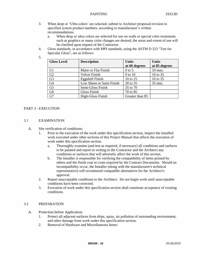
PAINTING 1933.ID
3. When deep or ‘Ultra colors’ are selected, submit to Architect proposed revision to specified system product numbers, according to manufacturer’s written recommendations.a. When deep or ultra colors are selected for use on walls or special color treatments
such as graphics or many color changes are desired, the areas and extent of use will be clarified upon request of the Contractor.
4. Gloss standards, in accordance with MPI standards, using the ASTM D 523 "Test for Specular Gloss", are as follows:
5.Gloss Level Description Units
at 60 degreesUnits at 85 degrees
G1 Matte or Flat Finish 0 to 5 10 max.G2 Velvet Finish 0 to 10 10 to 35G3 Eggshell Finish 10 to 25 10 to 35G4 Low Sheen or Satin Finish 20 to 35 35 min.G5 Semi-Gloss Finish 35 to 70G6 Gloss Finish 70 to 85G7 High-Gloss Finish Greater than 85
PART 3 - EXECUTION
3.1 EXAMINATION
A. Site verification of conditions:1. Prior to the execution of the work under this specification section, inspect the installed
work executed under other sections of this Project Manual that affects the execution of work under this specification section.a. Thoroughly examine (and test as required, if necessary) all conditions and surfaces
to be painted and report in writing to the Contractor and the Architect any conditions or surfaces that will adversely affect the work of this section.
b. The Installer is responsible for verifying the compatibility of items primed by others and the finish coat or coats required by the Contract Documents. Should an incompatibility occur, the Installer (along with the manufacturer's technical representative) will recommend compatible alternatives for the Architect's approval.
2. Report unacceptable conditions to the Architect. Do not begin work until unacceptable conditions have been corrected.
3. Execution of work under this specification section shall constitute acceptance of existing conditions.
3.2 PREPARATION
A. Protection before Application:1. Protect all adjacent surfaces from drips, spray, air pollution of surrounding environment,
and other damage from work under this specification section.2. Removal of Hardware and Miscellaneous Items:
099100 - 10 05/28/2019
PAINTING 1933.ID
a. Coordinate the work with other trades so that they remove electrical outlet and switch plates, mechanical diffusers, escutcheons, registers, surface hardware, fittings, fastenings, and the like prior to starting work under this Section.
b. Store during painting work. Coordinate cleaning and reinstallation after painting work is finished.
c. Do not use solvent or cleaning agents detrimental to permanent finishes.d. Remove doors before painting to paint bottom and top edges, and then re-hang.
3. Protect adjacent surfaces against damage from painting operations. Correct damage to work of other trades by cleaning, repairing, replacing, and refinishing, as approved by Architect, and leave in an undamaged condition.a. Protective means include: Drop cloths, shields, masking templates, etc.b. Exterior surfaces include: landscaping, walks, drives, adjacent building surfaces,
glazing, aluminum surfaces, etc.c. Interior surfaces include: rating and instruction labels on doors, frames, equipment,
piping, etc.
B. Surface preparation:1. General:
a. In accordance with MPI Standards.b. Surfaces to be finished shall be clean, dry and free of dirt, passivators, oils, loose
paint and any other contamination that would adversely affect adhesion, protective properties or appearance of the coating.
c. All oil, grease, dirt or other foreign matter shall be removed by washing with a solution of cleaner and water, rinse and allow to dry.
d. If efflorescence, alkali or glazed surfaces exist, neutralize with acid wash followed by thorough water rinsing.1) Protect all adjacent substrates or materials that could be affected by acid
washing or water rinsing. Collect all washing & rinsing residue and dispose of away from structures.
2. Wood Substrates - (New and Repaint Surfaces):a. Interior Surfaces: MPI Interior Surface Preparation, Chapter 3, Section 3.b. Exterior Surfaces: MPI Exterior Surface Preparation, Chapter 2, Section 3.c. Fill holes and other imperfections with putty or plastic wood to match natural finish
before and after application of prime or seal coat.d. Provide necessary extra treatment over knots, pitch pockets, sappy portions and
other defects to produce a proper base for painting.e. Sand down raised grain or rough surfaces.f. Clean surfaces free of dust, soil and other foreign material.
3. Gypsum Board Substrates - (New and Repaint Surfaces):a. Interior Surfaces: MPI Interior Surface Preparation, Chapter 3, Section 3.b. Clean surfaces of dirt, laitance , excess mortar and foreign matter.c. Do all necessary minor sanding.d. Fill minor cracks, scratches, holes and nail heads.
4. Plaster Substrates - (New and Repaint Surfaces):a. Interior Surfaces: MPI Interior Surface Preparation, Chapter 3, Section 3.b. Exterior Surfaces: MPI Exterior Surface Preparation, Chapter 2, Section 3.c. Clean surfaces of dirt, laitance, excess mortar and foreign matter.d. Neatly patch, flush and smooth, minor cracks, holes, pits and other imperfections in
plaster or concrete surfaces.5. Concrete Substrates - (New and Repaint Surfaces):
a. Interior Surfaces: MPI Interior Surface Preparation, Chapter 3, Section 3.
099100 - 11 05/28/2019
PAINTING 1933.ID
b. Exterior Surfaces: MPI Exterior Surface Preparation, Chapter 2, Section 3.c. Clean surfaces of dirt, laitance, excess mortar and foreign matter.d. Neatly patch, flush and smooth, minor cracks, holes, pits and other imperfections in
plaster or concrete surfaces.6. Metal Substrates - (New and Repaint Surfaces):
a. Interior Surfaces: MPI Interior Surface Preparation, Chapter 3, Section 3.b. Exterior Surfaces: MPI Exterior Surface Preparation, Chapter 2, Section 3.c. Shop Primed or Factory Primed Surfaces:
1) Shop Primed or Factory Primed Surfaces are considered "un-primed" due to their mil thicknesses provided, and common incompatibility issues with specified coating system; and are suitable only for protection during transit (shipment and storage) until incorporated into the Project.
2) Remove dust, oil and rust.3) Sand surface lightly.4) Touch up imperfections, scratches, surface damage, etc. with the
appropriate primer.5) Field connection welds, soldered joints, burned and abraded portions shall
be spot primed with the appropriate primer.d. Coil-Coated Product Surfaces:
1) Coil-Coated Product Surfaces are considered "un-primed" due to their mil thicknesses provided, and the common incompatibility issues with specified coating system; and are suitable only for protection during shipment and storage until incorporated into the Project.
2) Remove dust, oil and rust.3) Touch up imperfections, scratches, surface damage, etc. with the
appropriate primer.4) Field connection welds, burned and abraded portions shall be spot primed
with the appropriate primer.5) Field apply manufacturer's written recommended primer coat over entire
surface compatible with substrate finish and finish coats indicated on the paint schedule.
e. Un-primed Surfaces:1) Remove dust, rust, mill scale, grease and foreign matter by sand blasting or
wire brushing.2) Surfaces to be smooth and ready to receive coatings.
f. Non-Ferrous Metal, Galvanized, Aluminum, and Copper Surfaces:1) Metal Etch and Solvent Clean per SSPC-SP 1 or clean with TSP or other
appropriate cleaner followed by thorough water rinsing.2) Brush Blast to standards of SSPC-SP 16, or if blasting is not feasible, sand
thoroughly, wipe clean and apply a test patch for the coating specified.3) Allow system to cure at least one week, then test adhesion per ASTM D
3359 “Standard Test Methods for Measuring Adhesion by Tape Test”.7. Concrete Block Surfaces - (New and Repaint Surfaces):
a. Interior Surfaces: MPI Interior Surface Preparation, Chapter 3, Section 3.b. Exterior Surfaces: MPI Exterior Surface Preparation, Chapter 2, Section 3.c. Clean and free of all dirt, dust, rust, oil and free from all foreign matter.d. Test for moisture content.
1) Do not coat if moisture is present.2) Concrete Blocks to be thoroughly dry and cured prior to coating.
e. Do not coat Masonry wall if joints are not properly pointed, has excessive mortar drippings cracked units or shows signs of excessive efflorescence.
099100 - 12 05/28/2019
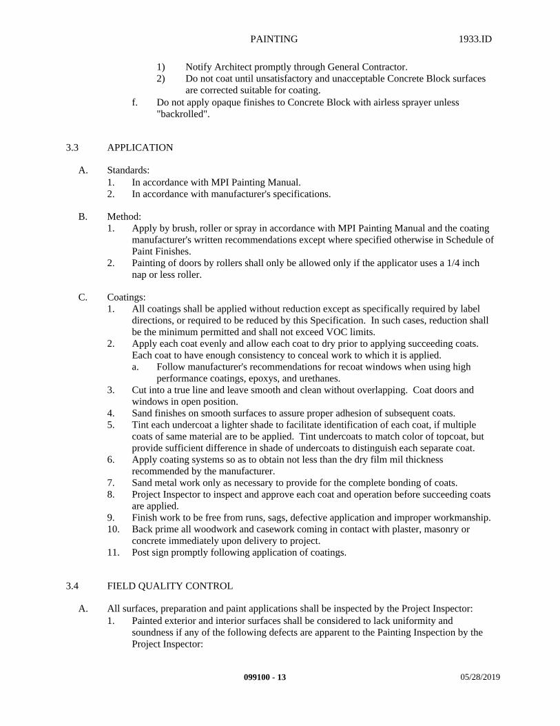
PAINTING 1933.ID
1) Notify Architect promptly through General Contractor.2) Do not coat until unsatisfactory and unacceptable Concrete Block surfaces
are corrected suitable for coating.f. Do not apply opaque finishes to Concrete Block with airless sprayer unless
"backrolled".
3.3 APPLICATION
A. Standards:1. In accordance with MPI Painting Manual.2. In accordance with manufacturer's specifications.
B. Method:1. Apply by brush, roller or spray in accordance with MPI Painting Manual and the coating
manufacturer's written recommendations except where specified otherwise in Schedule of Paint Finishes.
2. Painting of doors by rollers shall only be allowed only if the applicator uses a 1/4 inch nap or less roller.
C. Coatings:1. All coatings shall be applied without reduction except as specifically required by label
directions, or required to be reduced by this Specification. In such cases, reduction shall be the minimum permitted and shall not exceed VOC limits.
2. Apply each coat evenly and allow each coat to dry prior to applying succeeding coats. Each coat to have enough consistency to conceal work to which it is applied.a. Follow manufacturer's recommendations for recoat windows when using high
performance coatings, epoxys, and urethanes.3. Cut into a true line and leave smooth and clean without overlapping. Coat doors and
windows in open position.4. Sand finishes on smooth surfaces to assure proper adhesion of subsequent coats.5. Tint each undercoat a lighter shade to facilitate identification of each coat, if multiple
coats of same material are to be applied. Tint undercoats to match color of topcoat, but provide sufficient difference in shade of undercoats to distinguish each separate coat.
6. Apply coating systems so as to obtain not less than the dry film mil thickness recommended by the manufacturer.
7. Sand metal work only as necessary to provide for the complete bonding of coats.8. Project Inspector to inspect and approve each coat and operation before succeeding coats
are applied.9. Finish work to be free from runs, sags, defective application and improper workmanship.10. Back prime all woodwork and casework coming in contact with plaster, masonry or
concrete immediately upon delivery to project.11. Post sign promptly following application of coatings.
3.4 FIELD QUALITY CONTROL
A. All surfaces, preparation and paint applications shall be inspected by the Project Inspector:1. Painted exterior and interior surfaces shall be considered to lack uniformity and
soundness if any of the following defects are apparent to the Painting Inspection by the Project Inspector:
099100 - 13 05/28/2019
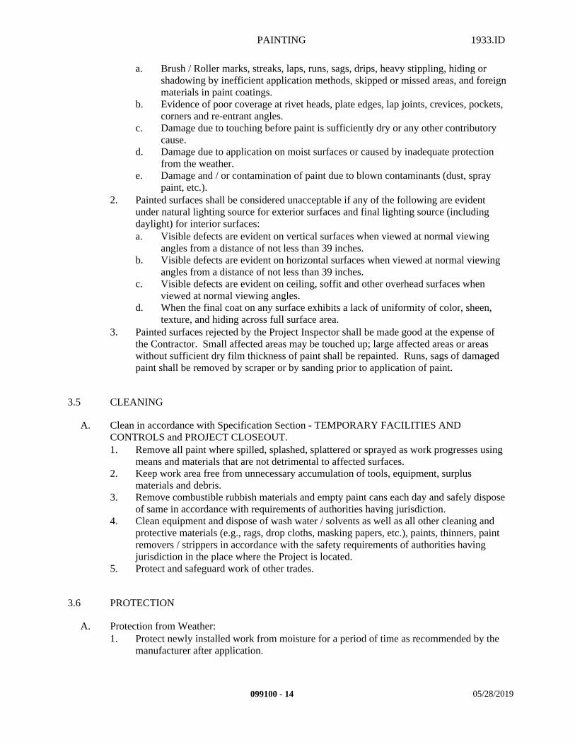
PAINTING 1933.ID
a. Brush / Roller marks, streaks, laps, runs, sags, drips, heavy stippling, hiding or shadowing by inefficient application methods, skipped or missed areas, and foreign materials in paint coatings.
b. Evidence of poor coverage at rivet heads, plate edges, lap joints, crevices, pockets, corners and re-entrant angles.
c. Damage due to touching before paint is sufficiently dry or any other contributory cause.
d. Damage due to application on moist surfaces or caused by inadequate protection from the weather.
e. Damage and / or contamination of paint due to blown contaminants (dust, spray paint, etc.).
2. Painted surfaces shall be considered unacceptable if any of the following are evident under natural lighting source for exterior surfaces and final lighting source (including daylight) for interior surfaces:a. Visible defects are evident on vertical surfaces when viewed at normal viewing
angles from a distance of not less than 39 inches.b. Visible defects are evident on horizontal surfaces when viewed at normal viewing
angles from a distance of not less than 39 inches.c. Visible defects are evident on ceiling, soffit and other overhead surfaces when
viewed at normal viewing angles.d. When the final coat on any surface exhibits a lack of uniformity of color, sheen,
texture, and hiding across full surface area.3. Painted surfaces rejected by the Project Inspector shall be made good at the expense of
the Contractor. Small affected areas may be touched up; large affected areas or areas without sufficient dry film thickness of paint shall be repainted. Runs, sags of damaged paint shall be removed by scraper or by sanding prior to application of paint.
3.5 CLEANING
A. Clean in accordance with Specification Section - TEMPORARY FACILITIES AND CONTROLS and PROJECT CLOSEOUT.1. Remove all paint where spilled, splashed, splattered or sprayed as work progresses using
means and materials that are not detrimental to affected surfaces.2. Keep work area free from unnecessary accumulation of tools, equipment, surplus
materials and debris.3. Remove combustible rubbish materials and empty paint cans each day and safely dispose
of same in accordance with requirements of authorities having jurisdiction.4. Clean equipment and dispose of wash water / solvents as well as all other cleaning and
protective materials (e.g., rags, drop cloths, masking papers, etc.), paints, thinners, paint removers / strippers in accordance with the safety requirements of authorities having jurisdiction in the place where the Project is located.
5. Protect and safeguard work of other trades.
3.6 PROTECTION
A. Protection from Weather:1. Protect newly installed work from moisture for a period of time as recommended by the
manufacturer after application.
099100 - 14 05/28/2019
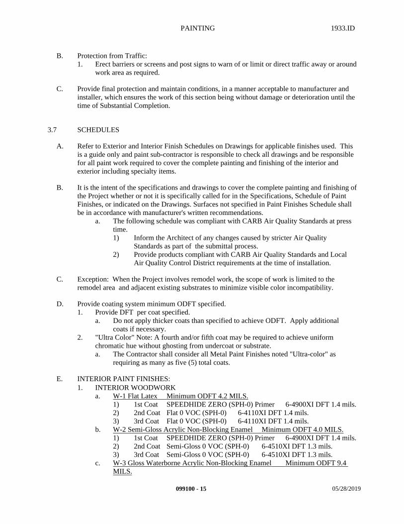
PAINTING 1933.ID
B. Protection from Traffic: 1. Erect barriers or screens and post signs to warn of or limit or direct traffic away or around
work area as required.
C. Provide final protection and maintain conditions, in a manner acceptable to manufacturer and installer, which ensures the work of this section being without damage or deterioration until the time of Substantial Completion.
3.7 SCHEDULES
A. Refer to Exterior and Interior Finish Schedules on Drawings for applicable finishes used. This is a guide only and paint sub-contractor is responsible to check all drawings and be responsible for all paint work required to cover the complete painting and finishing of the interior and exterior including specialty items.
B. It is the intent of the specifications and drawings to cover the complete painting and finishing of the Project whether or not it is specifically called for in the Specifications, Schedule of Paint Finishes, or indicated on the Drawings. Surfaces not specified in Paint Finishes Schedule shall be in accordance with manufacturer's written recommendations.
a. The following schedule was compliant with CARB Air Quality Standards at press time. 1) Inform the Architect of any changes caused by stricter Air Quality
Standards as part of the submittal process.2) Provide products compliant with CARB Air Quality Standards and Local
Air Quality Control District requirements at the time of installation.
C. Exception: When the Project involves remodel work, the scope of work is limited to the remodel area and adjacent existing substrates to minimize visible color incompatibility.
D. Provide coating system minimum ODFT specified.1. Provide DFT per coat specified.
a. Do not apply thicker coats than specified to achieve ODFT. Apply additional coats if necessary.
2. "Ultra Color" Note: A fourth and/or fifth coat may be required to achieve uniform chromatic hue without ghosting from undercoat or substrate. a. The Contractor shall consider all Metal Paint Finishes noted "Ultra-color" as
requiring as many as five (5) total coats.
E. INTERIOR PAINT FINISHES:1. INTERIOR WOODWORK
a. W-1 Flat Latex Minimum ODFT 4.2 MILS. 1) 1st Coat SPEEDHIDE ZERO (SPH-0) Primer 6-4900XI DFT 1.4 mils.2) 2nd Coat Flat 0 VOC (SPH-0) 6-4110XI DFT 1.4 mils.3) 3rd Coat Flat 0 VOC (SPH-0) 6-4110XI DFT 1.4 mils.
b. W-2 Semi-Gloss Acrylic Non-Blocking Enamel Minimum ODFT 4.0 MILS.1) 1st Coat SPEEDHIDE ZERO (SPH-0) Primer 6-4900XI DFT 1.4 mils.2) 2nd Coat Semi-Gloss 0 VOC (SPH-0) 6-4510XI DFT 1.3 mils.3) 3rd Coat Semi-Gloss 0 VOC (SPH-0) 6-4510XI DFT 1.3 mils.
c. W-3 Gloss Waterborne Acrylic Non-Blocking Enamel Minimum ODFT 9.4 MILS.
099100 - 15 05/28/2019
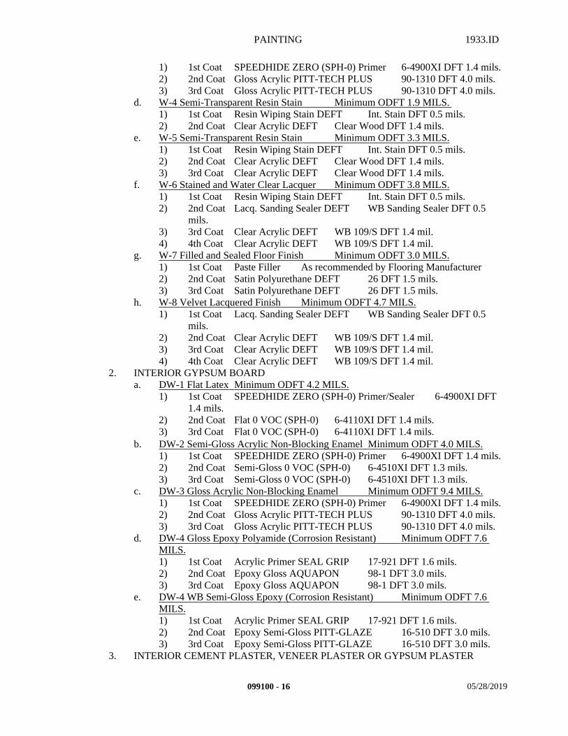
PAINTING 1933.ID
1) 1st Coat SPEEDHIDE ZERO (SPH-0) Primer 6-4900XI DFT 1.4 mils.2) 2nd Coat Gloss Acrylic PITT-TECH PLUS 90-1310 DFT 4.0 mils.3) 3rd Coat Gloss Acrylic PITT-TECH PLUS 90-1310 DFT 4.0 mils.
d. W-4 Semi-Transparent Resin Stain Minimum ODFT 1.9 MILS. 1) 1st Coat Resin Wiping Stain DEFT Int. Stain DFT 0.5 mils.2) 2nd Coat Clear Acrylic DEFT Clear Wood DFT 1.4 mils.
e. W-5 Semi-Transparent Resin Stain Minimum ODFT 3.3 MILS. 1) 1st Coat Resin Wiping Stain DEFT Int. Stain DFT 0.5 mils.2) 2nd Coat Clear Acrylic DEFT Clear Wood DFT 1.4 mils.3) 3rd Coat Clear Acrylic DEFT Clear Wood DFT 1.4 mils.
f. W-6 Stained and Water Clear Lacquer Minimum ODFT 3.8 MILS. 1) 1st Coat Resin Wiping Stain DEFT Int. Stain DFT 0.5 mils.2) 2nd Coat Lacq. Sanding Sealer DEFT WB Sanding Sealer DFT 0.5
mils.3) 3rd Coat Clear Acrylic DEFT WB 109/S DFT 1.4 mil.4) 4th Coat Clear Acrylic DEFT WB 109/S DFT 1.4 mil.
g. W-7 Filled and Sealed Floor Finish Minimum ODFT 3.0 MILS.1) 1st Coat Paste Filler As recommended by Flooring Manufacturer2) 2nd Coat Satin Polyurethane DEFT 26 DFT 1.5 mils.3) 3rd Coat Satin Polyurethane DEFT 26 DFT 1.5 mils.
h. W-8 Velvet Lacquered Finish Minimum ODFT 4.7 MILS.1) 1st Coat Lacq. Sanding Sealer DEFT WB Sanding Sealer DFT 0.5
mils.2) 2nd Coat Clear Acrylic DEFT WB 109/S DFT 1.4 mil.3) 3rd Coat Clear Acrylic DEFT WB 109/S DFT 1.4 mil.4) 4th Coat Clear Acrylic DEFT WB 109/S DFT 1.4 mil.
2. INTERIOR GYPSUM BOARD a. DW-1 Flat Latex Minimum ODFT 4.2 MILS.
1) 1st Coat SPEEDHIDE ZERO (SPH-0) Primer/Sealer 6-4900XI DFT 1.4 mils.
2) 2nd Coat Flat 0 VOC (SPH-0) 6-4110XI DFT 1.4 mils.3) 3rd Coat Flat 0 VOC (SPH-0) 6-4110XI DFT 1.4 mils.
b. DW-2 Semi-Gloss Acrylic Non-Blocking Enamel Minimum ODFT 4.0 MILS. 1) 1st Coat SPEEDHIDE ZERO (SPH-0) Primer 6-4900XI DFT 1.4 mils.2) 2nd Coat Semi-Gloss 0 VOC (SPH-0) 6-4510XI DFT 1.3 mils.3) 3rd Coat Semi-Gloss 0 VOC (SPH-0) 6-4510XI DFT 1.3 mils.
c. DW-3 Gloss Acrylic Non-Blocking Enamel Minimum ODFT 9.4 MILS. 1) 1st Coat SPEEDHIDE ZERO (SPH-0) Primer 6-4900XI DFT 1.4 mils.2) 2nd Coat Gloss Acrylic PITT-TECH PLUS 90-1310 DFT 4.0 mils.3) 3rd Coat Gloss Acrylic PITT-TECH PLUS 90-1310 DFT 4.0 mils.
d. DW-4 Gloss Epoxy Polyamide (Corrosion Resistant) Minimum ODFT 7.6 MILS. 1) 1st Coat Acrylic Primer SEAL GRIP 17-921 DFT 1.6 mils.2) 2nd Coat Epoxy Gloss AQUAPON 98-1 DFT 3.0 mils.3) 3rd Coat Epoxy Gloss AQUAPON 98-1 DFT 3.0 mils.
e. DW-4 WB Semi-Gloss Epoxy (Corrosion Resistant) Minimum ODFT 7.6 MILS. 1) 1st Coat Acrylic Primer SEAL GRIP 17-921 DFT 1.6 mils.2) 2nd Coat Epoxy Semi-Gloss PITT-GLAZE 16-510 DFT 3.0 mils.3) 3rd Coat Epoxy Semi-Gloss PITT-GLAZE 16-510 DFT 3.0 mils.
3. INTERIOR CEMENT PLASTER, VENEER PLASTER OR GYPSUM PLASTER
099100 - 16 05/28/2019
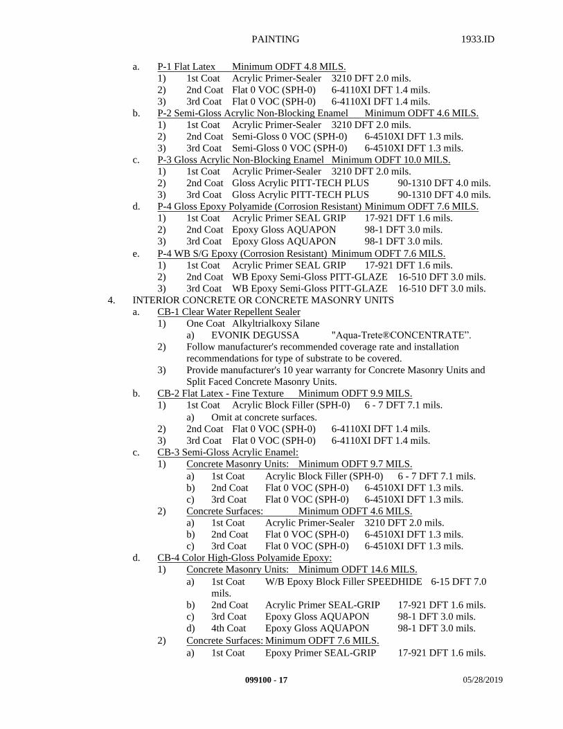
PAINTING 1933.ID
a. P-1 Flat Latex Minimum ODFT 4.8 MILS. 1) 1st Coat Acrylic Primer-Sealer 3210 DFT 2.0 mils.2) 2nd Coat Flat 0 VOC (SPH-0) 6-4110XI DFT 1.4 mils.3) 3rd Coat Flat 0 VOC (SPH-0) 6-4110XI DFT 1.4 mils.
b. P-2 Semi-Gloss Acrylic Non-Blocking Enamel Minimum ODFT 4.6 MILS. 1) 1st Coat Acrylic Primer-Sealer 3210 DFT 2.0 mils.2) 2nd Coat Semi-Gloss 0 VOC (SPH-0) 6-4510XI DFT 1.3 mils.3) 3rd Coat Semi-Gloss 0 VOC (SPH-0) 6-4510XI DFT 1.3 mils.
c. P-3 Gloss Acrylic Non-Blocking Enamel Minimum ODFT 10.0 MILS. 1) 1st Coat Acrylic Primer-Sealer 3210 DFT 2.0 mils.2) 2nd Coat Gloss Acrylic PITT-TECH PLUS 90-1310 DFT 4.0 mils.3) 3rd Coat Gloss Acrylic PITT-TECH PLUS 90-1310 DFT 4.0 mils.
d. P-4 Gloss Epoxy Polyamide (Corrosion Resistant) Minimum ODFT 7.6 MILS.1) 1st Coat Acrylic Primer SEAL GRIP 17-921 DFT 1.6 mils.2) 2nd Coat Epoxy Gloss AQUAPON 98-1 DFT 3.0 mils.3) 3rd Coat Epoxy Gloss AQUAPON 98-1 DFT 3.0 mils.
e. P-4 WB S/G Epoxy (Corrosion Resistant) Minimum ODFT 7.6 MILS. 1) 1st Coat Acrylic Primer SEAL GRIP 17-921 DFT 1.6 mils.2) 2nd Coat WB Epoxy Semi-Gloss PITT-GLAZE 16-510 DFT 3.0 mils.3) 3rd Coat WB Epoxy Semi-Gloss PITT-GLAZE 16-510 DFT 3.0 mils.
4. INTERIOR CONCRETE OR CONCRETE MASONRY UNITSa. CB-1 Clear Water Repellent Sealer
1) One Coat Alkyltrialkoxy Silane a) EVONIK DEGUSSA "Aqua-Trete®CONCENTRATE”.
2) Follow manufacturer's recommended coverage rate and installation recommendations for type of substrate to be covered.
3) Provide manufacturer's 10 year warranty for Concrete Masonry Units and Split Faced Concrete Masonry Units.
b. CB-2 Flat Latex - Fine Texture Minimum ODFT 9.9 MILS. 1) 1st Coat Acrylic Block Filler (SPH-0) 6 - 7 DFT 7.1 mils.
a) Omit at concrete surfaces.2) 2nd Coat Flat 0 VOC (SPH-0) 6-4110XI DFT 1.4 mils.3) 3rd Coat Flat 0 VOC (SPH-0) 6-4110XI DFT 1.4 mils.
c. CB-3 Semi-Gloss Acrylic Enamel:1) Concrete Masonry Units: Minimum ODFT 9.7 MILS.
a) 1st Coat Acrylic Block Filler (SPH-0) 6 - 7 DFT 7.1 mils. b) 2nd Coat Flat 0 VOC (SPH-0) 6-4510XI DFT 1.3 mils.c) 3rd Coat Flat 0 VOC (SPH-0) 6-4510XI DFT 1.3 mils.
2) Concrete Surfaces: Minimum ODFT 4.6 MILS.a) 1st Coat Acrylic Primer-Sealer 3210 DFT 2.0 mils.b) 2nd Coat Flat 0 VOC (SPH-0) 6-4510XI DFT 1.3 mils.c) 3rd Coat Flat 0 VOC (SPH-0) 6-4510XI DFT 1.3 mils.
d. CB-4 Color High-Gloss Polyamide Epoxy:1) Concrete Masonry Units: Minimum ODFT 14.6 MILS.
a) 1st Coat W/B Epoxy Block Filler SPEEDHIDE 6-15 DFT 7.0 mils.
b) 2nd Coat Acrylic Primer SEAL-GRIP 17-921 DFT 1.6 mils.c) 3rd Coat Epoxy Gloss AQUAPON 98-1 DFT 3.0 mils.d) 4th Coat Epoxy Gloss AQUAPON 98-1 DFT 3.0 mils.
2) Concrete Surfaces: Minimum ODFT 7.6 MILS.a) 1st Coat Epoxy Primer SEAL-GRIP 17-921 DFT 1.6 mils.
099100 - 17 05/28/2019
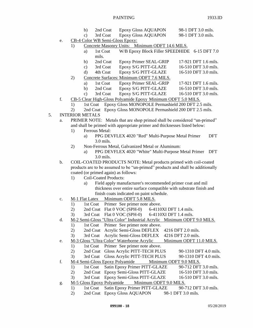
PAINTING 1933.ID
b) 2nd Coat Epoxy Gloss AQUAPON 98-1 DFT 3.0 mils.c) 3rd Coat Epoxy Gloss AQUAPON 98-1 DFT 3.0 mils.
e. CB-4 Color WB Semi-Gloss Epoxy:1) Concrete Masonry Units: Minimum ODFT 14.6 MILS.
a) 1st Coat W/B Epoxy Block Filler SPEEDHIDE 6-15 DFT 7.0 mils.
b) 2nd Coat Epoxy Primer SEAL-GRIP 17-921 DFT 1.6 mils.c) 3rd Coat Epoxy S/G PITT-GLAZE 16-510 DFT 3.0 mils.d) 4th Coat Epoxy S/G PITT-GLAZE 16-510 DFT 3.0 mils.
2) Concrete Surfaces: Minimum ODFT 7.6 MILS.a) 1st Coat Epoxy Primer SEAL-GRIP 17-921 DFT 1.6 mils.b) 2nd Coat Epoxy S/G PITT-GLAZE 16-510 DFT 3.0 mils.c) 3rd Coat Epoxy S/G PITT-GLAZE 16-510 DFT 3.0 mils.
f. CB-5 Clear High-Gloss Polyamide Epoxy Minimum ODFT 5.0 MILS. 1) 1st Coat Epoxy Gloss MONOPOLE Permashield 200 DFT 2.5 mils.2) 2nd Coat Epoxy Gloss MONOPOLE Permashield 200 DFT 2.5 mils.
5. INTERIOR METALS a. PRIMER NOTE: Metals that are shop primed shall be considered “un-primed”
and shall be primed with appropriate primer and thicknesses listed below: 1) Ferrous Metal:
a) PPG DEVFLEX 4020 "Red" Multi-Purpose Metal Primer DFT 3.0 mils.
2) Non-Ferrous Metal, Galvanized Metal or Aluminum:a) PPG DEVFLEX 4020 "White" Multi-Purpose Metal Primer DFT
3.0 mils.b. COIL-COATED PRODUCTS NOTE: Metal products primed with coil-coated
products are to be assumed to be “un-primed” products and shall be additionally coated (or primed again) as follows:1) Coil-Coated Products:
a) Field apply manufacturer's recommended primer coat and mil thickness over entire surface compatible with substrate finish and finish coats indicated on paint schedule.
c. M-1 Flat Latex Minimum ODFT 5.8 MILS. 1) 1st Coat Primer See primer note above.2) 2nd Coat Flat 0 VOC (SPH-0) 6-4110XI DFT 1.4 mils.3) 3rd Coat Flat 0 VOC (SPH-0) 6-4110XI DFT 1.4 mils.
d. M-2 Semi-Gloss "Ultra Color" Industrial Acrylic Minimum ODFT 9.0 MILS.1) 1st Coat Primer See primer note above.2) 2nd Coat Acrylic Semi-Gloss DEFLEX 4216 DFT 2.0 mils.3) 3rd Coat Acrylic Semi-Gloss DEFLEX 4216 DFT 2.0 mils.
e. M-3 Gloss "Ultra Color" Waterborne Acrylic Minimum ODFT 11.0 MILS.1) 1st Coat Primer See primer note above.2) 2nd Coat Gloss Acrylic PITT-TECH PLUS 90-1310 DFT 4.0 mils.3) 3rd Coat Gloss Acrylic PITT-TECH PLUS 90-1310 DFT 4.0 mils.
f. M-4 Semi-Gloss Epoxy Polyamide Minimum ODFT 9.0 MILS. 1) 1st Coat Satin Epoxy Primer PITT-GLAZE 90-712 DFT 3.0 mils.2) 2nd Coat Epoxy Semi-Gloss PITT-GLAZE 16-510 DFT 3.0 mils.3) 3rd Coat Epoxy Semi-Gloss PITT-GLAZE 16-510 DFT 3.0 mils.
g. M-5 Gloss Epoxy Polyamide Minimum ODFT 9.0 MILS. 1) 1st Coat Satin Epoxy Primer PITT-GLAZE 90-712 DFT 3.0 mils.2) 2nd Coat Epoxy Gloss AQUAPON 98-1 DFT 3.0 mils.
099100 - 18 05/28/2019
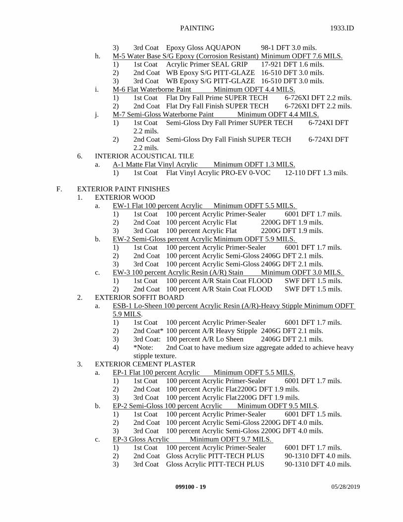
PAINTING 1933.ID
3) 3rd Coat Epoxy Gloss AQUAPON 98-1 DFT 3.0 mils.h. M-5 Water Base S/G Epoxy (Corrosion Resistant) Minimum ODFT 7.6 MILS.
1) 1st Coat Acrylic Primer SEAL GRIP 17-921 DFT 1.6 mils.2) 2nd Coat WB Epoxy S/G PITT-GLAZE 16-510 DFT 3.0 mils.3) 3rd Coat WB Epoxy S/G PITT-GLAZE 16-510 DFT 3.0 mils.
i. M-6 Flat Waterborne Paint Minimum ODFT 4.4 MILS. 1) 1st Coat Flat Dry Fall Prime SUPER TECH 6-726XI DFT 2.2 mils.2) 2nd Coat Flat Dry Fall Finish SUPER TECH 6-726XI DFT 2.2 mils.
j. M-7 Semi-Gloss Waterborne Paint Minimum ODFT 4.4 MILS. 1) 1st Coat Semi-Gloss Dry Fall Primer SUPER TECH 6-724XI DFT
2.2 mils.2) 2nd Coat Semi-Gloss Dry Fall Finish SUPER TECH 6-724XI DFT
2.2 mils.6. INTERIOR ACOUSTICAL TILE
a. A-1 Matte Flat Vinyl Acrylic Minimum ODFT 1.3 MILS. 1) 1st Coat Flat Vinyl Acrylic PRO-EV 0-VOC 12-110 DFT 1.3 mils.
F. EXTERIOR PAINT FINISHES1. EXTERIOR WOOD
a. EW-1 Flat 100 percent Acrylic Minimum ODFT 5.5 MILS. 1) 1st Coat 100 percent Acrylic Primer-Sealer 6001 DFT 1.7 mils.2) 2nd Coat 100 percent Acrylic Flat 2200G DFT 1.9 mils.3) 3rd Coat 100 percent Acrylic Flat 2200G DFT 1.9 mils.
b. EW-2 Semi-Gloss percent Acrylic Minimum ODFT 5.9 MILS. 1) 1st Coat 100 percent Acrylic Primer-Sealer 6001 DFT 1.7 mils.2) 2nd Coat 100 percent Acrylic Semi-Gloss 2406G DFT 2.1 mils.3) 3rd Coat 100 percent Acrylic Semi-Gloss 2406G DFT 2.1 mils.
c. EW-3 100 percent Acrylic Resin (A/R) Stain Minimum ODFT 3.0 MILS. 1) 1st Coat 100 percent A/R Stain Coat FLOOD SWF DFT 1.5 mils.2) 2nd Coat 100 percent A/R Stain Coat FLOOD SWF DFT 1.5 mils.
2. EXTERIOR SOFFIT BOARD a. ESB-1 Lo-Sheen 100 percent Acrylic Resin (A/R)-Heavy Stipple Minimum ODFT
5.9 MILS. 1) 1st Coat 100 percent Acrylic Primer-Sealer 6001 DFT 1.7 mils.2) 2nd Coat* 100 percent A/R Heavy Stipple 2406G DFT 2.1 mils.3) 3rd Coat: 100 percent A/R Lo Sheen 2406G DFT 2.1 mils.4) *Note: 2nd Coat to have medium size aggregate added to achieve heavy
stipple texture.3. EXTERIOR CEMENT PLASTER
a. EP-1 Flat 100 percent Acrylic Minimum ODFT 5.5 MILS. 1) 1st Coat 100 percent Acrylic Primer-Sealer 6001 DFT 1.7 mils.2) 2nd Coat 100 percent Acrylic Flat2200G DFT 1.9 mils.3) 3rd Coat 100 percent Acrylic Flat2200G DFT 1.9 mils.
b. EP-2 Semi-Gloss 100 percent Acrylic Minimum ODFT 9.5 MILS. 1) 1st Coat 100 percent Acrylic Primer-Sealer 6001 DFT 1.5 mils.2) 2nd Coat 100 percent Acrylic Semi-Gloss 2200G DFT 4.0 mils.3) 3rd Coat 100 percent Acrylic Semi-Gloss 2200G DFT 4.0 mils.
c. EP-3 Gloss Acrylic Minimum ODFT 9.7 MILS. 1) 1st Coat 100 percent Acrylic Primer-Sealer 6001 DFT 1.7 mils.2) 2nd Coat Gloss Acrylic PITT-TECH PLUS 90-1310 DFT 4.0 mils.3) 3rd Coat Gloss Acrylic PITT-TECH PLUS 90-1310 DFT 4.0 mils.
099100 - 19 05/28/2019
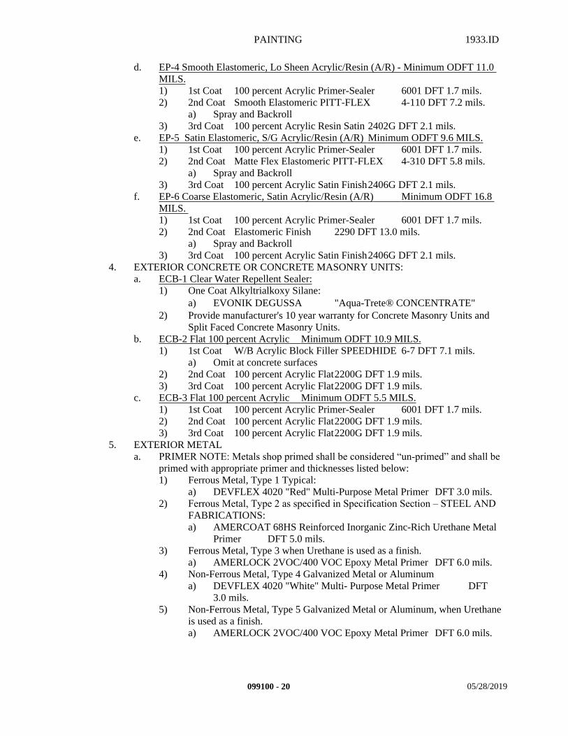
PAINTING 1933.ID
d. EP-4 Smooth Elastomeric, Lo Sheen Acrylic/Resin (A/R) - Minimum ODFT 11.0 MILS. 1) 1st Coat 100 percent Acrylic Primer-Sealer 6001 DFT 1.7 mils.2) 2nd Coat Smooth Elastomeric PITT-FLEX 4-110 DFT 7.2 mils.
a) Spray and Backroll3) 3rd Coat 100 percent Acrylic Resin Satin 2402G DFT 2.1 mils.
e. EP-5 Satin Elastomeric, S/G Acrylic/Resin (A/R) Minimum ODFT 9.6 MILS. 1) 1st Coat 100 percent Acrylic Primer-Sealer 6001 DFT 1.7 mils.2) 2nd Coat Matte Flex Elastomeric PITT-FLEX 4-310 DFT 5.8 mils.
a) Spray and Backroll3) 3rd Coat 100 percent Acrylic Satin Finish2406G DFT 2.1 mils.
f. EP-6 Coarse Elastomeric, Satin Acrylic/Resin (A/R) Minimum ODFT 16.8 MILS. 1) 1st Coat 100 percent Acrylic Primer-Sealer 6001 DFT 1.7 mils.2) 2nd Coat Elastomeric Finish 2290 DFT 13.0 mils.
a) Spray and Backroll3) 3rd Coat 100 percent Acrylic Satin Finish2406G DFT 2.1 mils.
4. EXTERIOR CONCRETE OR CONCRETE MASONRY UNITS:a. ECB-1 Clear Water Repellent Sealer:
1) One Coat Alkyltrialkoxy Silane:a) EVONIK DEGUSSA "Aqua-Trete® CONCENTRATE"
2) Provide manufacturer's 10 year warranty for Concrete Masonry Units and Split Faced Concrete Masonry Units.
b. ECB-2 Flat 100 percent Acrylic Minimum ODFT 10.9 MILS. 1) 1st Coat W/B Acrylic Block Filler SPEEDHIDE 6-7 DFT 7.1 mils.
a) Omit at concrete surfaces2) 2nd Coat 100 percent Acrylic Flat2200G DFT 1.9 mils.3) 3rd Coat 100 percent Acrylic Flat2200G DFT 1.9 mils.
c. ECB-3 Flat 100 percent Acrylic Minimum ODFT 5.5 MILS. 1) 1st Coat 100 percent Acrylic Primer-Sealer 6001 DFT 1.7 mils.2) 2nd Coat 100 percent Acrylic Flat2200G DFT 1.9 mils.3) 3rd Coat 100 percent Acrylic Flat2200G DFT 1.9 mils.
5. EXTERIOR METALa. PRIMER NOTE: Metals shop primed shall be considered “un-primed” and shall be
primed with appropriate primer and thicknesses listed below:1) Ferrous Metal, Type 1 Typical:
a) DEVFLEX 4020 "Red" Multi-Purpose Metal Primer DFT 3.0 mils.2) Ferrous Metal, Type 2 as specified in Specification Section – STEEL AND
FABRICATIONS:a) AMERCOAT 68HS Reinforced Inorganic Zinc-Rich Urethane Metal
Primer DFT 5.0 mils.3) Ferrous Metal, Type 3 when Urethane is used as a finish.
a) AMERLOCK 2VOC/400 VOC Epoxy Metal Primer DFT 6.0 mils.4) Non-Ferrous Metal, Type 4 Galvanized Metal or Aluminum
a) DEVFLEX 4020 "White" Multi- Purpose Metal Primer DFT 3.0 mils.
5) Non-Ferrous Metal, Type 5 Galvanized Metal or Aluminum, when Urethane is used as a finish.a) AMERLOCK 2VOC/400 VOC Epoxy Metal Primer DFT 6.0 mils.
099100 - 20 05/28/2019
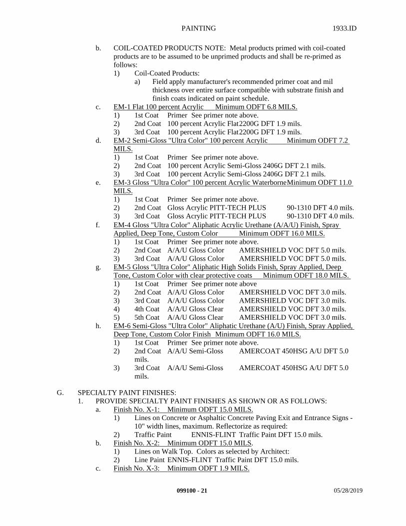
PAINTING 1933.ID
b. COIL-COATED PRODUCTS NOTE: Metal products primed with coil-coated products are to be assumed to be unprimed products and shall be re-primed as follows:1) Coil-Coated Products:
a) Field apply manufacturer's recommended primer coat and mil thickness over entire surface compatible with substrate finish and finish coats indicated on paint schedule.
c. EM-1 Flat 100 percent Acrylic Minimum ODFT 6.8 MILS.1) 1st Coat Primer See primer note above.2) 2nd Coat 100 percent Acrylic Flat2200G DFT 1.9 mils.3) 3rd Coat 100 percent Acrylic Flat2200G DFT 1.9 mils.
d. EM-2 Semi-Gloss "Ultra Color" 100 percent Acrylic Minimum ODFT 7.2 MILS.1) 1st Coat Primer See primer note above.2) 2nd Coat 100 percent Acrylic Semi-Gloss 2406G DFT 2.1 mils.3) 3rd Coat 100 percent Acrylic Semi-Gloss 2406G DFT 2.1 mils.
e. EM-3 Gloss "Ultra Color" 100 percent Acrylic WaterborneMinimum ODFT 11.0 MILS.1) 1st Coat Primer See primer note above.2) 2nd Coat Gloss Acrylic PITT-TECH PLUS 90-1310 DFT 4.0 mils.3) 3rd Coat Gloss Acrylic PITT-TECH PLUS 90-1310 DFT 4.0 mils.
f. EM-4 Gloss "Ultra Color" Aliphatic Acrylic Urethane (A/A/U) Finish, Spray Applied, Deep Tone, Custom Color Minimum ODFT 16.0 MILS.1) 1st Coat Primer See primer note above.2) 2nd Coat A/A/U Gloss Color AMERSHIELD VOC DFT 5.0 mils.3) 3rd Coat A/A/U Gloss Color AMERSHIELD VOC DFT 5.0 mils.
g. EM-5 Gloss "Ultra Color" Aliphatic High Solids Finish, Spray Applied, Deep Tone, Custom Color with clear protective coats Minimum ODFT 18.0 MILS. 1) 1st Coat Primer See primer note above2) 2nd Coat A/A/U Gloss Color AMERSHIELD VOC DFT 3.0 mils.3) 3rd Coat A/A/U Gloss Color AMERSHIELD VOC DFT 3.0 mils.4) 4th Coat A/A/U Gloss Clear AMERSHIELD VOC DFT 3.0 mils.5) 5th Coat A/A/U Gloss Clear AMERSHIELD VOC DFT 3.0 mils.
h. EM-6 Semi-Gloss "Ultra Color" Aliphatic Urethane (A/U) Finish, Spray Applied, Deep Tone, Custom Color Finish Minimum ODFT 16.0 MILS.1) 1st Coat Primer See primer note above.2) 2nd Coat A/A/U Semi-Gloss AMERCOAT 450HSG A/U DFT 5.0
mils.3) 3rd Coat A/A/U Semi-Gloss AMERCOAT 450HSG A/U DFT 5.0
mils.
G. SPECIALTY PAINT FINISHES:1. PROVIDE SPECIALTY PAINT FINISHES AS SHOWN OR AS FOLLOWS:
a. Finish No. X-1: Minimum ODFT 15.0 MILS. 1) Lines on Concrete or Asphaltic Concrete Paving Exit and Entrance Signs -
10" width lines, maximum. Reflectorize as required:2) Traffic Paint ENNIS-FLINT Traffic Paint DFT 15.0 mils.
b. Finish No. X-2: Minimum ODFT 15.0 MILS.1) Lines on Walk Top. Colors as selected by Architect:2) Line Paint ENNIS-FLINT Traffic Paint DFT 15.0 mils.
c. Finish No. X-3: Minimum ODFT 1.9 MILS.
099100 - 21 05/28/2019
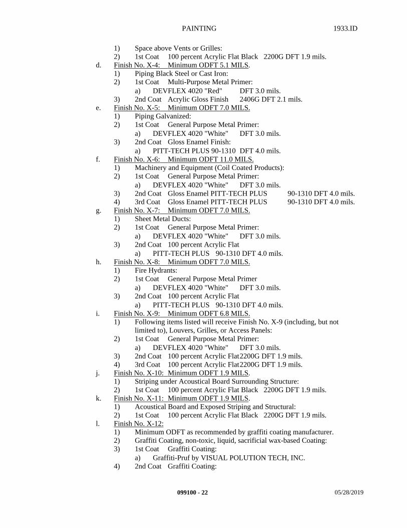
PAINTING 1933.ID
1) Space above Vents or Grilles:2) 1st Coat 100 percent Acrylic Flat Black 2200G DFT 1.9 mils.
d. Finish No. X-4: Minimum ODFT 5.1 MILS.1) Piping Black Steel or Cast Iron:2) 1st Coat Multi-Purpose Metal Primer:
a) DEVFLEX 4020 "Red" DFT 3.0 mils.3) 2nd Coat Acrylic Gloss Finish 2406G DFT 2.1 mils.
e. Finish No. X-5: Minimum ODFT 7.0 MILS.1) Piping Galvanized:2) 1st Coat General Purpose Metal Primer:
a) DEVFLEX 4020 "White" DFT 3.0 mils.3) 2nd Coat Gloss Enamel Finish:
a) PITT-TECH PLUS 90-1310 DFT 4.0 mils.f. Finish No. X-6: Minimum ODFT 11.0 MILS.
1) Machinery and Equipment (Coil Coated Products):2) 1st Coat General Purpose Metal Primer:
a) DEVFLEX 4020 "White" DFT 3.0 mils.3) 2nd Coat Gloss Enamel PITT-TECH PLUS 90-1310 DFT 4.0 mils.4) 3rd Coat Gloss Enamel PITT-TECH PLUS 90-1310 DFT 4.0 mils.
g. Finish No. X-7: Minimum ODFT 7.0 MILS.1) Sheet Metal Ducts:2) 1st Coat General Purpose Metal Primer:
a) DEVFLEX 4020 "White" DFT 3.0 mils.3) 2nd Coat 100 percent Acrylic Flat
a) PITT-TECH PLUS 90-1310 DFT 4.0 mils.h. Finish No. X-8: Minimum ODFT 7.0 MILS.
1) Fire Hydrants:2) 1st Coat General Purpose Metal Primer
a) DEVFLEX 4020 "White" DFT 3.0 mils.3) 2nd Coat 100 percent Acrylic Flat
a) PITT-TECH PLUS 90-1310 DFT 4.0 mils.i. Finish No. X-9: Minimum ODFT 6.8 MILS.
1) Following items listed will receive Finish No. X-9 (including, but not limited to), Louvers, Grilles, or Access Panels:
2) 1st Coat General Purpose Metal Primer:a) DEVFLEX 4020 "White" DFT 3.0 mils.
3) 2nd Coat 100 percent Acrylic Flat2200G DFT 1.9 mils.4) 3rd Coat 100 percent Acrylic Flat2200G DFT 1.9 mils.
j. Finish No. X-10: Minimum ODFT 1.9 MILS. 1) Striping under Acoustical Board Surrounding Structure: 2) 1st Coat 100 percent Acrylic Flat Black 2200G DFT 1.9 mils.
k. Finish No. X-11: Minimum ODFT 1.9 MILS. 1) Acoustical Board and Exposed Striping and Structural: 2) 1st Coat 100 percent Acrylic Flat Black 2200G DFT 1.9 mils.
l. Finish No. X-12: 1) Minimum ODFT as recommended by graffiti coating manufacturer. 2) Graffiti Coating, non-toxic, liquid, sacrificial wax-based Coating: 3) 1st Coat Graffiti Coating:
a) Graffiti-Pruf by VISUAL POLUTION TECH, INC.4) 2nd Coat Graffiti Coating:
099100 - 22 05/28/2019
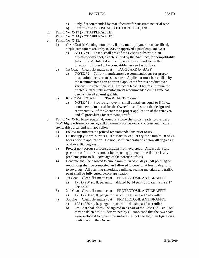
PAINTING 1933.ID
a) Only if recommended by manufacturer for substrate material type. b) Graffiti-Pruf by VISUAL POLUTION TECH, INC.
m. Finish No. X-13 (NOT APPLICABLE): n. Finish No. X-14 (NOT APPLICABLE):o. Finish No. X-15:
1) Clear Graffiti Coating, non-toxic, liquid, multi-polymer, non-sacrificial, single component sealer by BASF, or approved equivalent: One Coata) NOTE #1: Test a small area of the existing substrate in an
out-of-the-way spot, as determined by the Architect, for compatibility. Inform the Architect if an incompatibility is found for further direction. If found to be compatible, proceed as follows:
2) 1st Coat Clear, flat matte coat TAGGUARD by BASFa) NOTE #2: Follow manufacturer's recommendations for proper
installation over various substrates. Applicator must be certified by the manufacturer as an approved applicator for this product over various substrate materials. Protect at least 24 hours minimum the treated surface until manufacturer's recommended curing time has been achieved against graffiti.
3) REMOVAL COAT: TAGGUARD Cleanera) NOTE #3: Provide remover in small containers equal to 8-16 oz.
containers of material for the Owner's use. Instruct the designated representative of the Owner as to proper application of the remover, and all procedures for removing graffiti.
p. Finish No. X-16: Non-sacraficial, aqueous, silane chemistry, ready-to-use, zero VOC high performance anti-graffiti treatment for masonry, concrete and natural stone, dries clear and will not yellow.1) Follow manufacturer's printed recommendations prior to use.2) Do not apply to wet surfaces. If surface is wet, let dry for a minimum of 24
hours prior to application. Do not use if temperature is below 40 degrees F or above 100 degrees F.
3) Protect non-porous surface substrates from overspray. Always do a test patch to confirm the treatment before using to deterimine if there is any problems prior to full coverage of the porous surfaces.
4) Concrete shall be allowed to cure a minimum of 28 days. All pointing or re-pointing shall be completed and allowed to cure for at least 3 days prior to coverage. All patching materials, caulking, sealing materials and traffic paint shall be fully cured before application.
5) 1st Coat Clear, flat matte coat PROTECTOSIL ANTIGRAFFITIa) 175 to 250 sq. ft. per gallon, diluted by 14 parts of water, using a 1"
nap roller.6) 2nd Coat Clear, flat matte coat PROTECTOSIL ANTIGRAFFITI
a) 175 to 250 sq. ft. per gallon, un-diluted, using a 1" nap roller.7) 3rd Coat Clear, flat matte coat PROTECTOSIL ANTIGRAFFITI
a) 175 to 250 sq. ft. per gallon, un-diluted, using a 1" nap roller.b) 3rd Coat shall always be figured in as part of the Base Bid. 3rd Coat
may be deleted if it is determined by all concerned that the two coats were sufficient to protect the surfaces. If not needed, then figure on a credit back to the Owner.
099100 - 23 05/28/2019
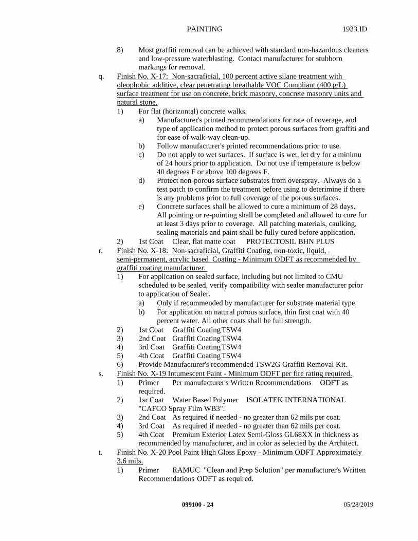
PAINTING 1933.ID
8) Most graffiti removal can be achieved with standard non-hazardous cleaners and low-pressure waterblasting. Contact manufacturer for stubborn markings for removal.
q. Finish No. X-17: Non-sacraficial, 100 percent active silane treatment with oleophobic additive, clear penetrating breathable VOC Compliant (400 g/L) surface treatment for use on concrete, brick masonry, concrete masonry units and natural stone.1) For flat (horizontal) concrete walks.
a) Manufacturer's printed recommendations for rate of coverage, and type of application method to protect porous surfaces from graffiti and for ease of walk-way clean-up.
b) Follow manufacturer's printed recommendations prior to use.c) Do not apply to wet surfaces. If surface is wet, let dry for a minimu
of 24 hours prior to application. Do not use if temperature is below 40 degrees F or above 100 degrees F.
d) Protect non-porous surface substrates from overspray. Always do a test patch to confirm the treatment before using to deterimine if there is any problems prior to full coverage of the porous surfaces.
e) Concrete surfaces shall be allowed to cure a minimum of 28 days. All pointing or re-pointing shall be completed and allowed to cure for at least 3 days prior to coverage. All patching materials, caulking, sealing materials and paint shall be fully cured before application.
2) 1st Coat Clear, flat matte coat PROTECTOSIL BHN PLUSr. Finish No. X-18: Non-sacraficial, Graffiti Coating, non-toxic, liquid,
semi-permanent, acrylic based Coating - Minimum ODFT as recommended by graffiti coating manufacturer. 1) For application on sealed surface, including but not limited to CMU
scheduled to be sealed, verify compatibility with sealer manufacturer prior to application of Sealer.a) Only if recommended by manufacturer for substrate material type.b) For application on natural porous surface, thin first coat with 40
percent water. All other coats shall be full strength.2) 1st Coat Graffiti Coating TSW4 3) 2nd Coat Graffiti Coating TSW4 4) 3rd Coat Graffiti Coating TSW4 5) 4th Coat Graffiti Coating TSW4 6) Provide Manufacturer's recommended TSW2G Graffiti Removal Kit.
s. Finish No. X-19 Intumescent Paint - Minimum ODFT per fire rating required.1) Primer Per manufacturer's Written Recommendations ODFT as
required.2) 1sr Coat Water Based Polymer ISOLATEK INTERNATIONAL
"CAFCO Spray Film WB3".3) 2nd Coat As required if needed - no greater than 62 mils per coat.4) 3rd Coat As required if needed - no greater than 62 mils per coat.5) 4th Coat Premium Exterior Latex Semi-Gloss GL68XX in thickness as
recommended by manufacturer, and in color as selected by the Architect.t. Finish No. X-20 Pool Paint High Gloss Epoxy - Minimum ODFT Approximately
3.6 mils.1) Primer RAMUC "Clean and Prep Solution" per manufacturer's Written
Recommendations ODFT as required.
099100 - 24 05/28/2019
PAINTING 1933.ID
2) 1st Coat Pool Paint by RAMUC ODFT 1.7 mils.3) Finish Coat Pool Paint by RAMUC ODFT 1.7 mils.
END OF SECTION
099100 - 25 05/28/2019

MISCELLANEOUS SPECIALTIES 1933.ID
SECTION 100500 – MISCELLANEOUS SPECIALTIES
PART 1 - GENERAL
1.1 SUMMARY
A. This Section includes the following:1. Provision for and installation of specialty and built-in items required for this Work as
indicated on the Drawings.
B. Related Sections: The following Sections contain requirements that relate to this Section:1. ALL DIVISION 00 SPECIFICATION SECTIONS.2. ALL DIVISION 01 SPECIFICATION SECTIONS.3. 03 30 00 CAST-IN-PLACE CONCRETE4. 05 12 00 STEEL AND FABRICATIONS5. 06 10 00 ROUGH CARPENTRY6. 06 41 23 MODULAR CASEWORK7. 08 80 00 GLASS8. 09 11 00 METAL FRAMING9. 09 29 00 GYPSUM BOARD10. 09 50 00 ACOUSTICAL CEILINGS11. 09 65 10 RESILIENT BASE AND ACCESSORIES12. 09 65 19 RESILIENT TILE13. 09 91 00 PAINTING14. ALL SPECIFICATION SECTIONS IN THE FACILITY SERVICES SUBGROUP.15. ALL SPECIFICATION SECTIONS IN THE SITE AND INFRASTRUCTURE
SUBGROUP.
1.2 SYSTEM DESCRIPTION
A. Performance Requirements: It is the intention of this section and the drawings to form a guide for a complete and operable system of all products or systems listed within this specification section. Any items not specifically noted but necessary for a complete and operable product or system shall be provided under this section.
1.3 SUBMITTALS
A. Submit in accordance with Specification Section - SUBMITTAL PROCEDURES:1. Shop Drawings:
a. Submit Shop Drawings and catalog cuts to the architect showing all details of installation and assembly and all requirements for work by other trades.
2. Product Data:a. Submit manufacturer's full color range (including any standard, premium and
custom colors) for selection by the Architect.
100500 - 1 05/29/2019
MISCELLANEOUS SPECIALTIES 1933.ID
1.4 DELIVERY, STORAGE, AND HANDLING
A. Storage and protection: 1. Use all means necessary to protect all specialty items before, during and after installation
and to protect the installed work and materials of all other trades.
B. Replacements:1. In the event of damage, immediately make all repairs and replacements necessary to the
approval of the Architect at no additional cost to the Owner.
1.5 PROJECT CONDITIONS
A. Existing Conditions: 1. Surface Conditions:
a. Coordination: Coordinate with all other trades as required to ensure proper and adequate provision in framing and wall finish for the installation of the selected specialties in the locations required.
2. Inspection:a. Prior to Installation, inspect all specific locations and verify that all necessary
provisions have been made.b. In the event of discrepancy, immediately notify the Architect.c. Do not proceed with installation in areas of discrepancy until all such discrepancies
have been fully resolved.
1.6 WARRANTY
A. Contractor's General Warranty:1. In accordance with Specification Section - WARRANTIES.
B. Manufacturer’s Warranty:1. In accordance with manufacturer's written standard warranty:
a. Warranty Period One (1) Year.
C. Installer's Warranty:1. In accordance with the terms of the Specification Section - WARRANTIES:
a. Warranty period One (1) Year.
PART 2 - PRODUCTS
NOT APPLICABLE
100500 - 2 05/29/2019
MISCELLANEOUS SPECIALTIES 1933.ID
PART 3 - EXECUTION
3.1 INSTALLATION
A. Install all specialty items where indicated on the Drawings and in full accordance with all pertinent regulations and the manufacturer's written recommendations, anchoring all components firmly in place for long life under hard use, and in accordance with IR (Interpretation of Regulations, “Division of the State Architect”) Manual.
3.2 ADJUSTING
A. Upon completion of the installation, and as a condition of its acceptance, visually inspect the entire work of this Section, adjust all components for proper alignment and use, and touch up all abrasions and scratches to make them completely invisible.
3.3 SCHEDULES
A. All items shall be as scheduled or approved equivalent items as set forth in the Substitution Section of these specifications, and all provisions of Division 00 - GENERAL CONDITIONS, and the sections of Division 01.
B. Composite Cladding:1. Manufacturer: Fiberon Composite Cladding for Rainscreen Applications, Product Line:
Symmetry, Color: Warm Sienna. a. Mockups: Erect project-site mockup incorporating materials and workmanship
required. After mockup has been reviewed fo acceptability, retain on site and suitably protected until the work has been completed. Accepted mockup will serve as quality control standards for judging acceptability of the installed work. Accepted mockups may be incorporated into the work.
b. Composition: Wood and plastic composite core boards with polyethylene-based capping material, faux wood grain texture and color.
c. Board Thickness: 0.935 inch total, 0.015 inch capping material. d. Board Width: 5.4 inches. e. Board Length: longest length to match pattern shown.f. Board Edges: 1/8" radius.g. Gapping: per manufacturer's requirements. Temperature at installation is an
important factor in determining gap requirements. h. Performance Criteria:
1) Surface Burning Characteristics per ASTM E84: Class C, Max 200 Flame Spread Index, Max 350 Smoke Development Index.
2) Self-Ignition Temperature per ASTM D 1929: 743 degrees F.3) Flash-Ignition Temperature per ASTM D1929: 698 degrees F.4) Specific Gravity, per ASTM D792: 1.10.5) Coefficient of Thermal Expansion per ASTM D6341: 1.67 x 10^-5
in/in/degree Farenheit. 6) Modulus of Elasticity per ASTM 6109: 456,000 psi. 7) Modulus of Rupture per ASTM D6109: 3500 psi.
100500 - 3 05/29/2019
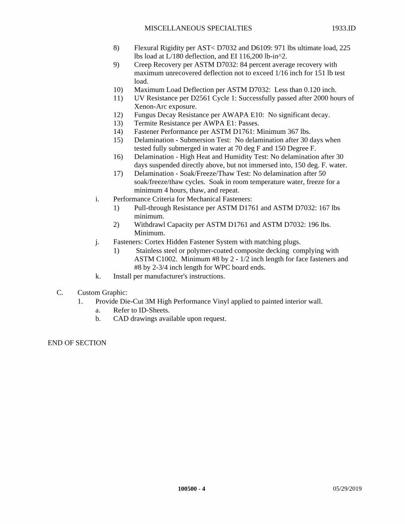
MISCELLANEOUS SPECIALTIES 1933.ID
8) Flexural Rigidity per AST< D7032 and D6109: 971 lbs ultimate load, 225 lbs load at L/180 deflection, and EI 116,200 lb-in^2.
9) Creep Recovery per ASTM D7032: 84 percent average recovery with maximum unrecovered deflection not to exceed 1/16 inch for 151 lb test load.
10) Maximum Load Deflection per ASTM D7032: Less than 0.120 inch.11) UV Resistance per D2561 Cycle 1: Successfully passed after 2000 hours of
Xenon-Arc exposure.12) Fungus Decay Resistance per AWAPA E10: No significant decay.13) Termite Resistance per AWPA E1: Passes. 14) Fastener Performance per ASTM D1761: Minimum 367 lbs.15) Delamination - Submersion Test: No delamination after 30 days when
tested fully submerged in water at 70 deg F and 150 Degree F.16) Delamination - High Heat and Humidity Test: No delamination after 30
days suspended directly above, but not immersed into, 150 deg. F. water. 17) Delamination - Soak/Freeze/Thaw Test: No delamination after 50
soak/freeze/thaw cycles. Soak in room temperature water, freeze for a minimum 4 hours, thaw, and repeat.
i. Performance Criteria for Mechanical Fasteners:1) Pull-through Resistance per ASTM D1761 and ASTM D7032: 167 lbs
minimum.2) Withdrawl Capacity per ASTM D1761 and ASTM D7032: 196 lbs.
Minimum.j. Fasteners: Cortex Hidden Fastener System with matching plugs.
1) Stainless steel or polymer-coated composite decking complying with ASTM C1002. Minimum #8 by 2 - 1/2 inch length for face fasteners and #8 by 2-3/4 inch length for WPC board ends.
k. Install per manufacturer's instructions.
C. Custom Graphic:1. Provide Die-Cut 3M High Performance Vinyl applied to painted interior wall.
a. Refer to ID-Sheets.b. CAD drawings available upon request.
END OF SECTION
100500 - 4 05/29/2019
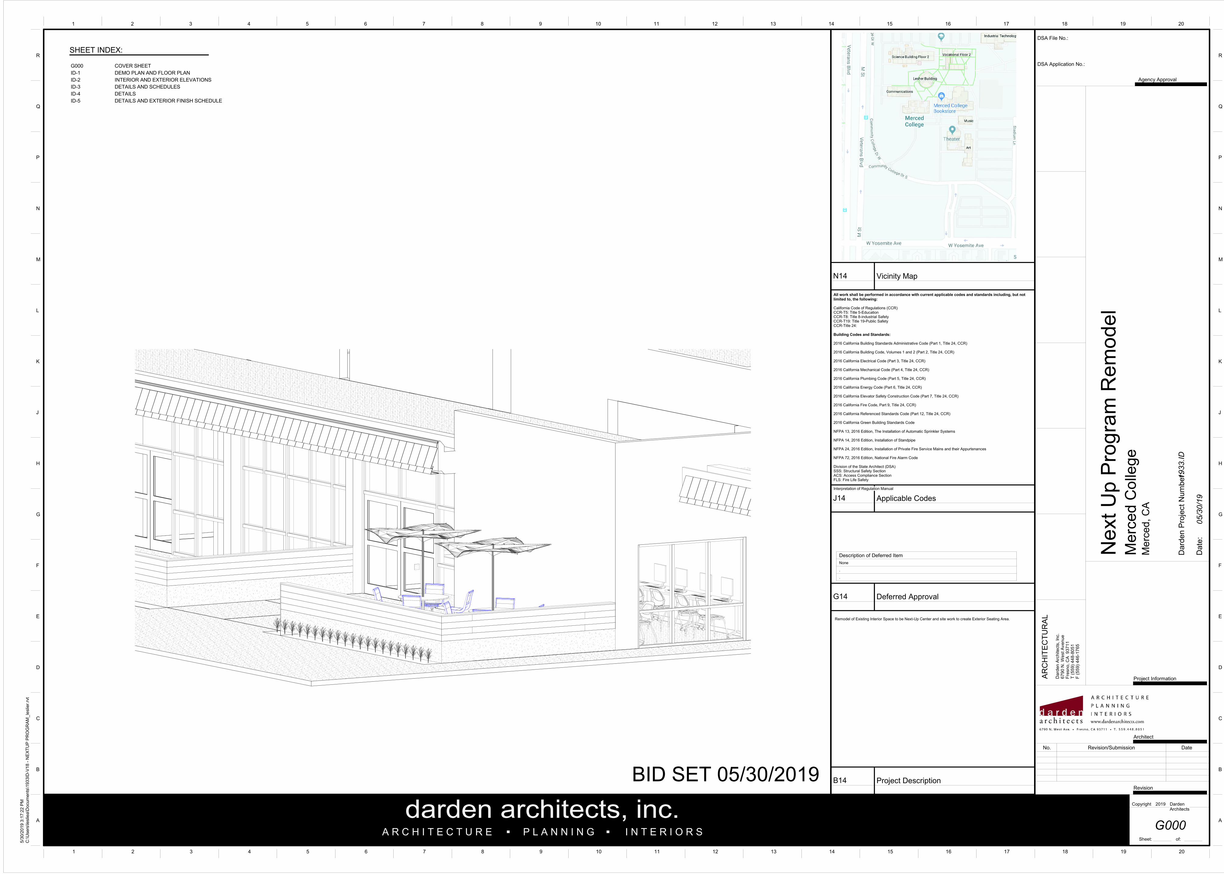
G000 COVER SHEET
ID-1 DEMO PLAN AND FLOOR PLAN
ID-2 INTERIOR AND EXTERIOR ELEVATIONS
ID-3 DETAILS AND SCHEDULES
ID-4 DETAILS
ID-5 DETAILS AND EXTERIOR FINISH SCHEDULE
SHEET INDEX:
DSA Application No.:
A
B
C
D
E
F
G
H
J
K
L
M
N
P
Q
R
A
B
C
D
E
F
G
H
J
K
L
M
N
P
Q
R
1 2 3 4 5 6 7 8 9 10 11 12 13 14 15 16 17 18 19 20
1 2 3 4 5 6 7 8 9 10 11 12 13 14 15 16 17 18 19 20
A R C H I T E C T U R E P L A N N I N G I N T E R I O R S
darden architects, inc...
Dard
en P
roje
ct
Num
be
r:
DSA File No.:
AR
CH
ITE
CT
UR
AL
Da
rden
Arc
hitects
, In
c.
679
0 N
. W
est A
ve
nu
eF
resn
o, C
A 9
371
1T
(55
9)
44
8-8
051
F
(55
9)
44
6-1
765
Description of Deferred Item
None
All work shall be performed in accordance with current applicable codes and standards including, but not
limited to, the following:
California Code of Regulations (CCR)CCR-T5: Title 5-EducationCCR-T8: Title 8-industrial SafetyCCR-T19: Title 19-Public SafetyCCR-Title 24:
Building Codes and Standards:
2016 California Building Standards Administrative Code (Part 1, Title 24, CCR)
2016 California Building Code, Volumes 1 and 2 (Part 2, Title 24, CCR)
2016 California Electrical Code (Part 3, Title 24, CCR)
2016 California Mechanical Code (Part 4, Title 24, CCR)
2016 California Plumbing Code (Part 5, Title 24, CCR)
2016 California Energy Code (Part 6, Title 24, CCR)
2016 California Elevator Safety Construction Code (Part 7, Title 24, CCR)
2016 California Fire Code, Part 9, Title 24, CCR)
2016 California Referenced Standards Code (Part 12, Title 24, CCR)
2016 California Green Building Standards Code
NFPA 13, 2016 Edition, The Installation of Automatic Sprinkler Systems
NFPA 14, 2016 Edition, Installation of Standpipe
NFPA 24, 2016 Edition, Installation of Private Fire Service Mains and their Appurtenances
NFPA 72, 2016 Edition, National Fire Alarm Code
Division of the State Architect (DSA)SSS: Structural Safety SectionACS: Access Compliance SectionFLS: Fire Life Safety
Interpretation of Regulation Manual
.
.
G14 Deferred Approval
Sheet: of:
Agency Approval
Revision
Copyright Darden Architects
Architect
Project Information
Date
:
J14 Applicable Codes
N14 Vicinity Map
B14 Project Description
5/3
0/2
019 3
:17:2
2 P
M
C:\U
sers
\leslie
a\D
ocum
ents
\1933ID
-V18 -
NE
XT
UP
PR
OG
RA
M_le
slie
r.rv
t
G000
Ne
xt
Up
Pro
gra
m R
em
od
el
Merc
ed C
olle
ge
Me
rce
d, C
A
1933.ID
2019
05/30/19
Remodel of Existing Interior Space to be Next-Up Center and site work to create Exterior Seating Area.
No. Revision/Submission Date
BID SET 05/30/2019
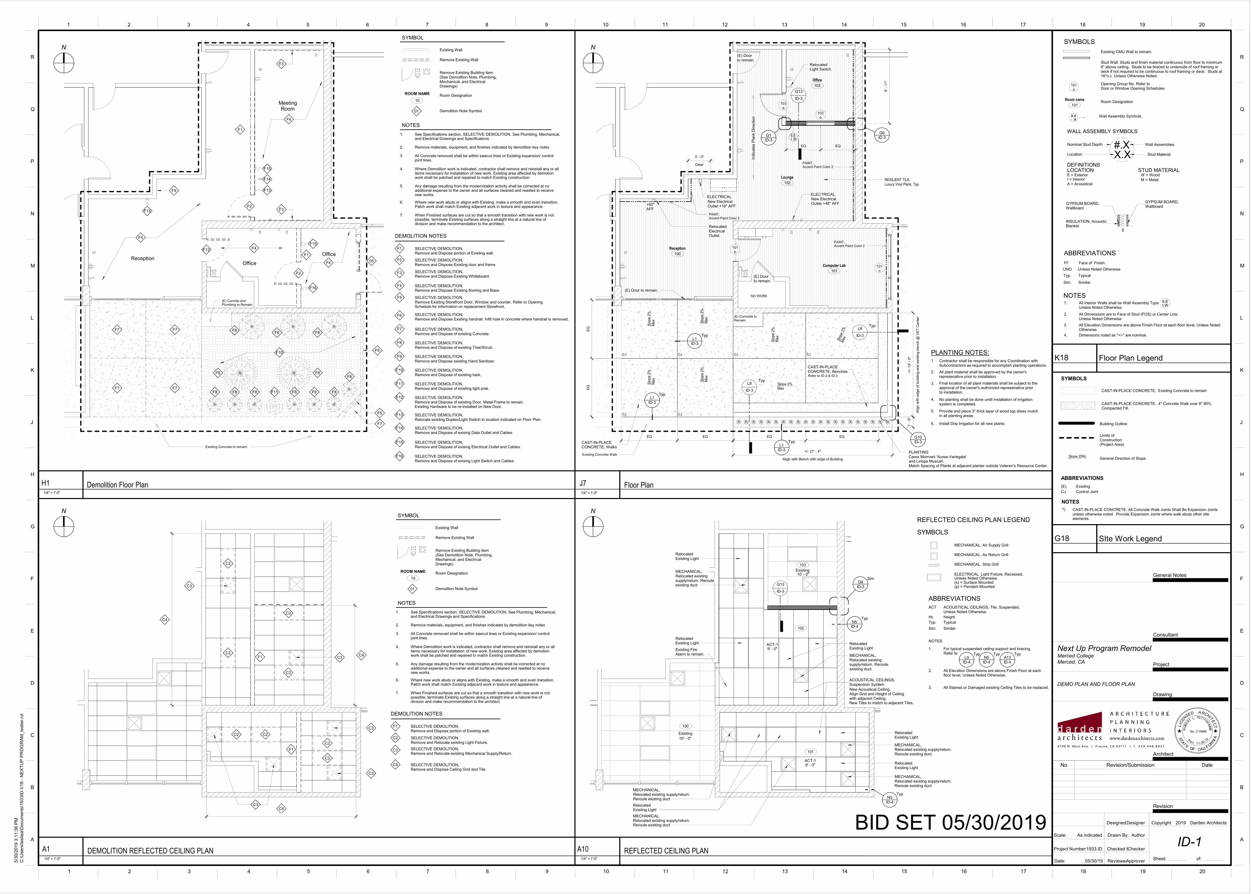
9' -
11"Office
103
Lounge
102
Reception
100
Computer Lab
101
PAINT, Accent Paint Color 2
PAINT, Accent Paint Color 2
CJ
CJ
CJ
CJ
CJ CJ
EQ EQ EQ EQ
EQ
EQ
Aligh with Bench with edge of Building
+/- 21' - 4"
Alig
n w
ith e
dge o
f b
uild
ing a
nd e
xis
ting b
ench @
VE
T C
ente
r
+/-
14' -
0"
1' -
5"
PAINT, Accent Paint Color 2
L8
ID-3
Typ
L8
ID-3
Typ
ID-3G10
(E) Concrete toRemain.
ID-3L1
Typ
ID-3L1
Typ
CAST-IN-PLACECONCRETE, Walks
Existing Concrete Walk
CAST-IN-PLACECONCRETE, Benches
Clear
3' - 0"
Refer to ID-2 & ID-3
103a
103b
101c
101b
.6.EI W
EQ EQ
NO WORK
ID-3
G1ID-3G6
G13
ID-3
Slo
pe
2%
Ma
x
Slo
pe
2%
Ma
x
Slo
pe
2%
Ma
x
Slo
pe 2
%M
ax
Slope 2%Max
Slo
pe
2%
Ma
x
Slo
pe
2%
Ma
x
(E) Doorto remain.
(E) Doorto remain.
(E) Door to remain.
Relocated Electrical Outlet.
Relocated Light Switch.
+60" AFF
ELECTRICALNew Electrical Outlet +48" AFF
ELECTRICAL
New Electrical Outlet +18" AFF
PLANTINGCarex Morrowii 'Aurea-Variegata'and Liriope Muscari.Match Spacing of Plants at adjacent planter outside Veteren's Resource Center.
RESILIENT TILE,Luxury Vinyl Plank, Typ.
Indic
ate
s P
lank D
irection
ID-3
L1Typ
F1
F2
F1
F2
05
F4
F4
F4
F4Reception
Meeting Room
Office
Office
F6
F6
F7
F8F8 F8
F8 F8
F8 F8 F8 F8 F8 F8
F8
F7 F7
F7 F7
Existing Concrete to remain.
F10
F11
F12
(E) Conrete and Plumbing to Remain.
F3
F3
F9
F13
F13
F15
F14
F15
F16
SELECTIVE DEMOLITION,Remove and Dispose portion of Existing wall.
SELECTIVE DEMOLITION,Remove and Dispose Existing door and frame
SELECTIVE DEMOLITION,Remove and Dispose Existing flooring and Base
DEMOLITION NOTES
Remove Existing Wall
Existing Wall
Remove Existing Building Item(See Demolition Note, Plumbing,Mechanical, and Electrical Drawings)
Room Designation
Demolition Note Symbol
SYMBOL
NOTES
1. See Specifications section, SELECTIVE DEMOLITION, See Plumbing, Mechanical,and Electrical Drawings and Specifications
2. Remove materials, equipment, and finishes indicated by demolition key notes
3. All Concrete removed shall be within sawcut lines or Existing expansion/ controljoint lines.
4. Where Demolition work is indicated, contractor shall remove and reinstall any or allitems necessary for installation of new work. Existing area affected by demotionwork shall be patched and repaired to match Existing construction.
5. Any damage resulting from the modernization activity shall be corrected at noadditional expense to the owner and all surfaces cleaned and readied to receivenew works.
6. Where new work abuts or aligns with Existing, make a smooth and even transition.Patch work shall match Existing adjacent work in texture and appearance.
7. When Finished surfaces are cut so that a smooth transition with new work is notpossible, terminate Existing surfaces along a straight line at a natural line ofdivision and make recommendation to the architect.
ROOM NAME
10
F1
F2
F3
F4
01
SELECTIVE DEMOLITION,Remove Existing Storefront Door, Window and counter. Refer to Opening Schedule for information on replacement Storefront.
F5
SELECTIVE DEMOLITION,Remove and Dispose Existing handrail. Infill hole in concrete where handrail is removed.
F6
SELECTIVE DEMOLITION,Remove and Dispose of existing Concrete.
F7
SELECTIVE DEMOLITION,Remove and Dispose of existing Tree/Shrub.
F8
SELECTIVE DEMOLITION,Remove and Dispose of existing bark.
F10
SELECTIVE DEMOLITION,Remove and Dispose of existing light pole.
F11
SELECTIVE DEMOLITION,Remove and Dispose of existing Door. Metal Frame to remain.Existing Hardware to be re-installed on New Door.
F12
SELECTIVE DEMOLITION,Remove and Dispose existing Hand Sanitizer.
F9
SELECTIVE DEMOLITION,Remove and Dispose Existing Whiteboard.
SELECTIVE DEMOLITION,Relocate existing Duplex/Light Switch to location indicated on Floor Plan.
F13
SELECTIVE DEMOLITION,Remove and Dispose of exising Data Outlet and Cables.
F14
SELECTIVE DEMOLITION,Remove and Dispose of exising Electrical Outlet and Cables.
F15
SELECTIVE DEMOLITION,Remove and Dispose of exising Light Switch and Cables.
F16
Stud Wall. Studs and finish material continuous from floor to minimum 6" above ceiling. Studs to be braced to underside of roof framing or deck if not required to be continuous to roof framing or deck. Studs at 16"o.c. Unless Otherwise Noted.
Existing CMU Wall to remain.
1. All Interior Walls shall be Wall Assembly Type Unless Noted Otherwise.
2. All Dimensions are to Face of Stud (FOS) or Center Line,Unless Noted Otherwise.
Room Designation
Opening Group No. Refer to Door or Window Opening Schedules
Wall Assembly Symbols.
SYMBOLS
NOTES
ABBREVIATIONS
FF Face of Finish
4. Dimensions noted as "+/-" are nominal.
UNO Unless Noted Otherwise
6.EI.W
Typ. Typical
Sim. Similar
3. All Elevation Dimensions are above Finish Floor at each floor level, Unless Noted Otherwise.
101a
.#.#- #
Room name
101
General Direction of Slope
Building Outline
Limits of Construction(Project Area)
SYMBOLS
ABBREVIATIONS
NOTES
1) CAST-IN-PLACE CONCRETE, All Concrete Walk Joints Shall Be Expansion Joints unless otherwise noted. Provide Expansion Joints where walk abuts other site elements.
(E) Existing
CAST-IN-PLACE CONCRETE, 4" Concrete Walk over 6" 90% Compacted Fill.
CJ Control Joint
Slope (DN)
CAST-IN-PLACE CONCRETE, Existing Concrete to remain
C2
F1
F1
C2
C2
C3
C3
C4
C4
C2
.
C3
C2C2
C3
.
.C4
C2
C2
C3
Relocated Existing Light
Relocated Existing Light
100
102
103
101
10' - 0"
10' - 0"
G13
ID-3ID-3G6
Sim
ACT-19' - 0"
ACOUSTICAL CEILINGS,Suspension System
New Acoustical Ceiling. Align Grid and Height of Ceilingwith adjacent Ceiling. New Tiles to match to adjacent Tiles.
Relocated Existing Light
MECHANICAL,Relocated existing supply/return. Reroute existing duct.
ACOUSTICAL CEILINGS,Suspension System
ID-4N5
Typ
ID-4N5
Typ
MECHANICAL,Relocated existing supply/return. Reroute existing duct.
MECHANICAL,Relocated existing supply/return. Reroute existing duct.
Relocated Existing Light
Relocated Existing Light
MECHANICAL,Relocated existing supply/return. Reroute existing duct
MECHANICAL,Relocated existing supply/return. Reroute existing duct
Relocated Existing Light
MECHANICAL,Relocated existing supply/return. Reroute existing duct
ACT-19' - 0"
Existing
Existing
Existing Fire Alarm to remain.
ACT ACOUSTICAL CEILINGS, Tile, Suspended, Unless Noted Otherwise.
Ht. Height
Typ. Typical
Sim. Similar
ABBREVIATIONS
NOTES
2. All Elevation Dimensions are above Finish Floor at eachfloor level, Unless Noted Otherwise.
1. For typical suspended ceiling support and bracing, Refer to
ELECTRICAL, Light Fixture, Recessed.
MECHANICAL, Air Supply Grill
MECHANICAL, Air Return Grill
MECHANICAL, Strip Grill
Unless Noted Otherwise.(s) = Surface Mounted(p) = Pendant Mounted
SYMBOLS
ID-4L9
Typ
REFLECTED CEILING PLAN LEGEND
3. All Stained or Damaged existing Ceiling Tiles to be replaced.
ID-4N5
Typ
ID-4A13
Typ
SELECTIVE DEMOLITION,Remove and Dispose portion of Existing wall.
SELECTIVE DEMOLITION,Remove and Relocate exisitng Light Fixture.
SELECTIVE DEMOLITION,Remove and Relocate existing Mechanical Supply/Return.
SELECTIVE DEMOLITION,Remove and Dispose Ceiling Grid and Tile.
DEMOLITION NOTES
Remove Existing Wall
Existing Wall
Remove Existing Building Item(See Demolition Note, Plumbing,Mechanical, and Electrical Drawings)
Room Designation
Demolition Note Symbol
SYMBOL
NOTES
1. See Specifications section, SELECTIVE DEMOLITION, See Plumbing, Mechanical,and Electrical Drawings and Specifications
2. Remove materials, equipment, and finishes indicated by demolition key notes
3. All Concrete removed shall be within sawcut lines or Existing expansion/ controljoint lines.
4. Where Demolition work is indicated, contractor shall remove and reinstall any or allitems necessary for installation of new work. Existing area affected by demotionwork shall be patched and repaired to match Existing construction.
5. Any damage resulting from the modernization activity shall be corrected at noadditional expense to the owner and all surfaces cleaned and readied to receivenew works.
6. Where new work abuts or aligns with Existing, make a smooth and even transition.Patch work shall match Existing adjacent work in texture and appearance.
7. When Finished surfaces are cut so that a smooth transition with new work is notpossible, terminate Existing surfaces along a straight line at a natural line ofdivision and make recommendation to the architect.
ROOM NAME
10
F1
C2
C3
C4
01
LOCATION STUD MATERIAL
#.XX.X
WALL ASSEMBLY SYMBOLS
DEFINITIONS
Nominal Stud Depth
Location Stud Material
Wall Assemblies
E = ExteriorI = Interior
W = Wood
M = MetalA = Acoustical
GYPSUM BOARD,Wallboard
GYPSUM BOARD,Wallboard
E
INSULATION, AcousticBlanket
PLANTING NOTES:Contractor shall be responsible for any Coordination withSubcontractors as required to accomplish planting operations.
1.
All plant material shall be approved by the owner's represenative prior to installation.
2.
Final location of all plant materials shall be subject to theapproval of the owner's authorized represenative priorto installation.
3.
No planting shall be done untill installation of irrigation system is completed.
4.
Provide and place 3" thick layer of wood top dress mulchin all planting areas.
5.
Install Drip Irrigation for all new plants. 6.
TC
ETI
HCRAES
N
ECI
L
D
RO
BE
RTPETITHO
MM
L.
E
No. C15968
AL FORNI
STA
TE
OF C I
A
11 30R
en. --
Scale:
Date:
Checked By:
Reviewed By:
Project Number:
A
B
C
D
E
F
G
H
J
K
L
M
N
P
Q
R
A
B
C
D
E
F
G
H
J
K
L
M
N
P
Q
R
Drawn By:
Designed By:
Drawing
Project
Consultant
1 2 3 4 5 6 7 8 9 10 11 12 13 14 15 16 17 18 19 20
1 2 3 4 5 6 7 8 9 10 11 12 13 14 15 16 17 18 19 20
General Notes
19
Revision
Sheet: of:
Copyright Darden Architects
Architect
BID SET 05/30/2019As indicated
5/3
0/2
019 3
:11:3
6 P
M
C:\U
sers
\leslie
a\D
ocum
ents
\1933ID
-V18 -
NE
XT
UP
PR
OG
RA
M_le
slie
r.rv
t
ID-1
DEMO PLAN AND FLOOR PLAN
Merced College
Next Up Program Remodel
Checker
Author
05/30/19
1933.ID
Approver
Designer
Merced, CA
2019
1/4" = 1'-0"
J7 Floor Plan1/4" = 1'-0"
H1 Demolition Floor Plan
K18 Floor Plan Legend
G18 SIte Work Legend
1/4" = 1'-0"
A1 DEMOLITION REFLECTED CEILING PLAN1/4" = 1'-0"
A10 REFLECTED CEILING PLAN
N
N
N
N
No. Revision/Submission Date
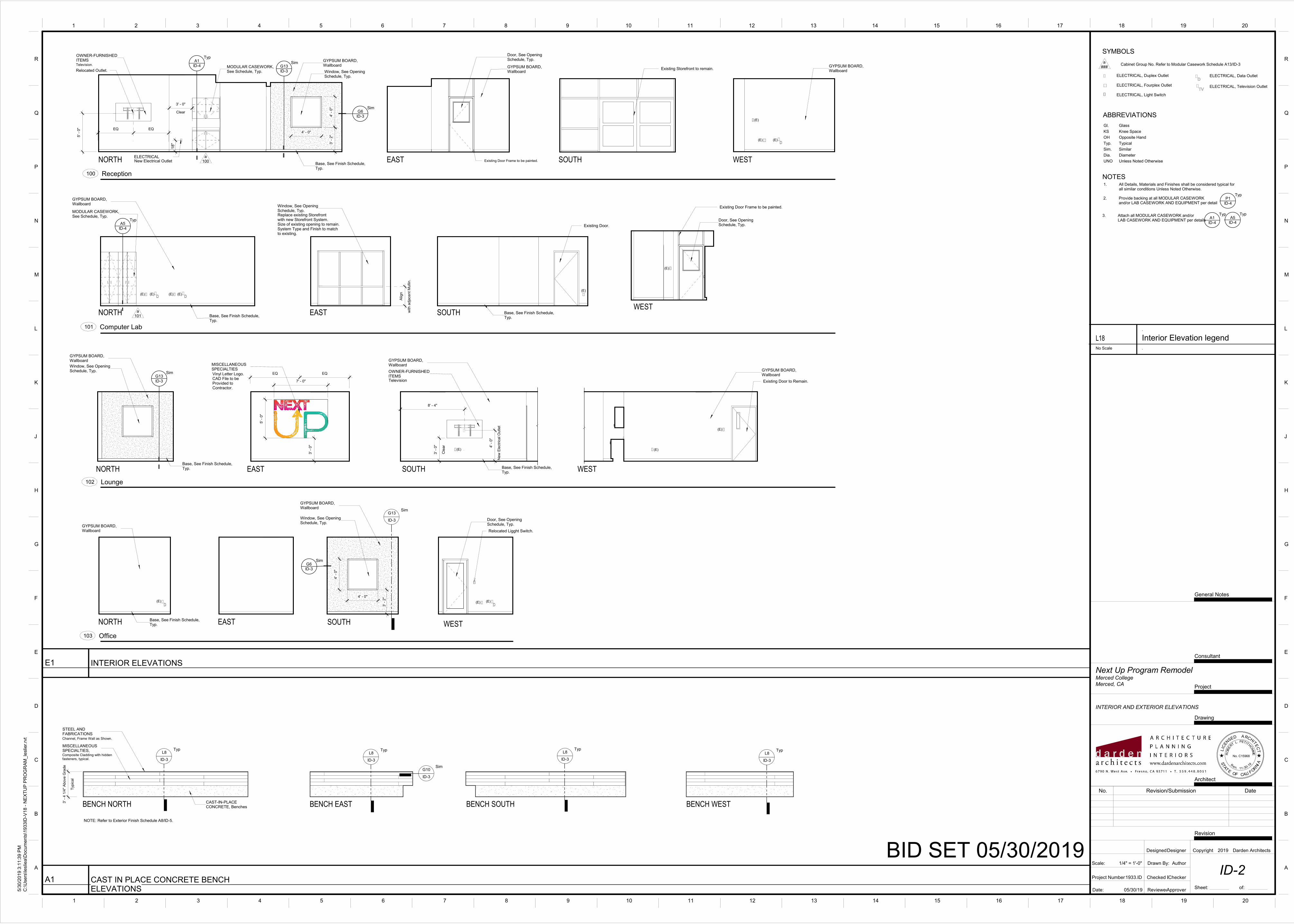
GYPSUM BOARD,Wallboard
Door, See OpeningSchedule, Typ.
Existing Door Frame to be painted.
EQEQ
Reception100
Clear
3' - 0"
5' -
0"
4' - 0"
4' -
0"
GYPSUM BOARD,Wallboard
Window, See OpeningSchedule, Typ.
Base, See Finish Schedule,Typ.
MODULAR CASEWORK,See Schedule, Typ.
a100
OWNER-FURNISHEDITEMSTelevision.
3' -
2"
ID-4A1
Typ
ID-3G13
Sim
ID-3G6
Sim
Relocated Outlet.
ELECTRICAL
18"
New Electrical Outlet
Existing Storefront to remain.GYPSUM BOARD,Wallboard
(E)
(E) (E)
Window, See OpeningSchedule, Typ.Replace existing Storefrontwith new Storefront System.Size of existing opening to remain.System Type and Finish to matchto existing.
with a
dja
cent M
ulli
n.
Alig
n
Computer Lab101
MODULAR CASEWORK,See Schedule, Typ.
a101
GYPSUM BOARD,Wallboard
Base, See Finish Schedule,Typ.
ID-4A5
Typ
(E) (E) (E) (E)
Base, See Finish Schedule,Typ.
Existing Door.
(E)
Door, See OpeningSchedule, Typ.
Existing Door Frame to be painted.
(E)
Lounge102
Window, See OpeningSchedule, Typ.
GYPSUM BOARD,Wallboard
Base, See Finish Schedule,Typ.
ID-3G13
Sim
3' -
0"
EQ EQ
5' -
0"
7' - 0"
MISCELLANEOUSSPECIALTIESVinyl Letter Logo.CAD File to be Provided to Contractor.
Cle
ar
3' -
0"
OWNER-FURNISHEDITEMS
Base, See Finish Schedule,Typ.
GYPSUM BOARD,Wallboard
8' - 4"
(E)
New
Ele
ctr
ical O
utlet
4' -
0"
Television Existing Door to Remain.
GYPSUM BOARD,Wallboard
(E)
(E)
Office103
GYPSUM BOARD,Wallboard
Base, See Finish Schedule,Typ.
(E)
GYPSUM BOARD,Wallboard
Window, See OpeningSchedule, Typ.
4' - 0"
4' -
0"
3' -
2"
G13
ID-3
Sim
ID-3G6
Sim
Door, See OpeningSchedule, Typ.
(E)(E)
Relocated Ligght Switch.
Typic
al
3' -
4 1
/4"
Above G
rade
STEEL ANDFABRICATIONSChannel, Frame Wall as Shown.
MISCELLANEOUSSPECIALTIES,Composite Cladding with hiddenfasteners, typical.
CAST-IN-PLACECONCRETE, Benches
L8
ID-3
TypL8
ID-3
Typ
G10
ID-3
Sim
L8
ID-3
TypL8
ID-3
Typ
ABBREVIATIONS
SYMBOLS
NOTES
L18 Interior Elevation legend
.
No Scale .
UNO Unless Noted Otherwise
ELECTRICAL, Television Outlet
ELECTRICAL, Duplex Outlet
ELECTRICAL, Light Switch
Cabinet Group No. Refer to Modular Casework Schedule A13/ID-3
ELECTRICAL, Data Outlet
ELECTRICAL, Fourplex Outlet
1. All Details, Materials and Finishes shall be considered typical forall similar conditions Unless Noted Otherwise.
KS Knee Space
Typ. Typical
Dia. Diameter
OH Opposite Hand
3. Attach all MODULAR CASEWORK and/orLAB CASEWORK AND EQUIPMENT per details
Sim. Similar
Gl. Glass
2. Provide backing at all MODULAR CASEWORKand/or LAB CASEWORK AND EQUIPMENT per detail
a###
ID-4A5
Typ
ID-4
A1Typ
ID-4
P1Typ
TC
ETI
HCRAES
NE
CIL
D
RO
BE
RTPETITHO
MM
L.
E
No. C15968
AL FORNI
STA
TE
OF C I
A
11 30R
en. --
Scale:
Date:
Checked By:
Reviewed By:
Project Number:
A
B
C
D
E
F
G
H
J
K
L
M
N
P
Q
R
A
B
C
D
E
F
G
H
J
K
L
M
N
P
Q
R
Drawn By:
Designed By:
Drawing
Project
Consultant
1 2 3 4 5 6 7 8 9 10 11 12 13 14 15 16 17 18 19 20
1 2 3 4 5 6 7 8 9 10 11 12 13 14 15 16 17 18 19 20
General Notes
19
Revision
Sheet: of:
Copyright Darden Architects
Architect
BID SET 05/30/20191/4" = 1'-0"
5/3
0/2
019 3
:11:3
9 P
M
C:\U
sers
\leslie
a\D
ocum
ents
\1933ID
-V18 -
NE
XT
UP
PR
OG
RA
M_le
slie
r.rv
t
ID-2
INTERIOR AND EXTERIOR ELEVATIONS
Merced College
Next Up Program Remodel
Checker
Author
05/30/19
1933.ID
Approver
Designer
Merced, CA
2019
EASTNORTH SOUTH WEST
EASTNORTH SOUTHWEST
NORTH EAST SOUTH WEST
NORTH EAST SOUTH WEST
E1 INTERIOR ELEVATIONS
BENCH NORTH BENCH EAST BENCH SOUTH BENCH WEST
A1 CAST IN PLACE CONCRETE BENCHELEVATIONS
NOTE: Refer to Exterior Finish Schedule A8/ID-5.
No. Revision/Submission Date
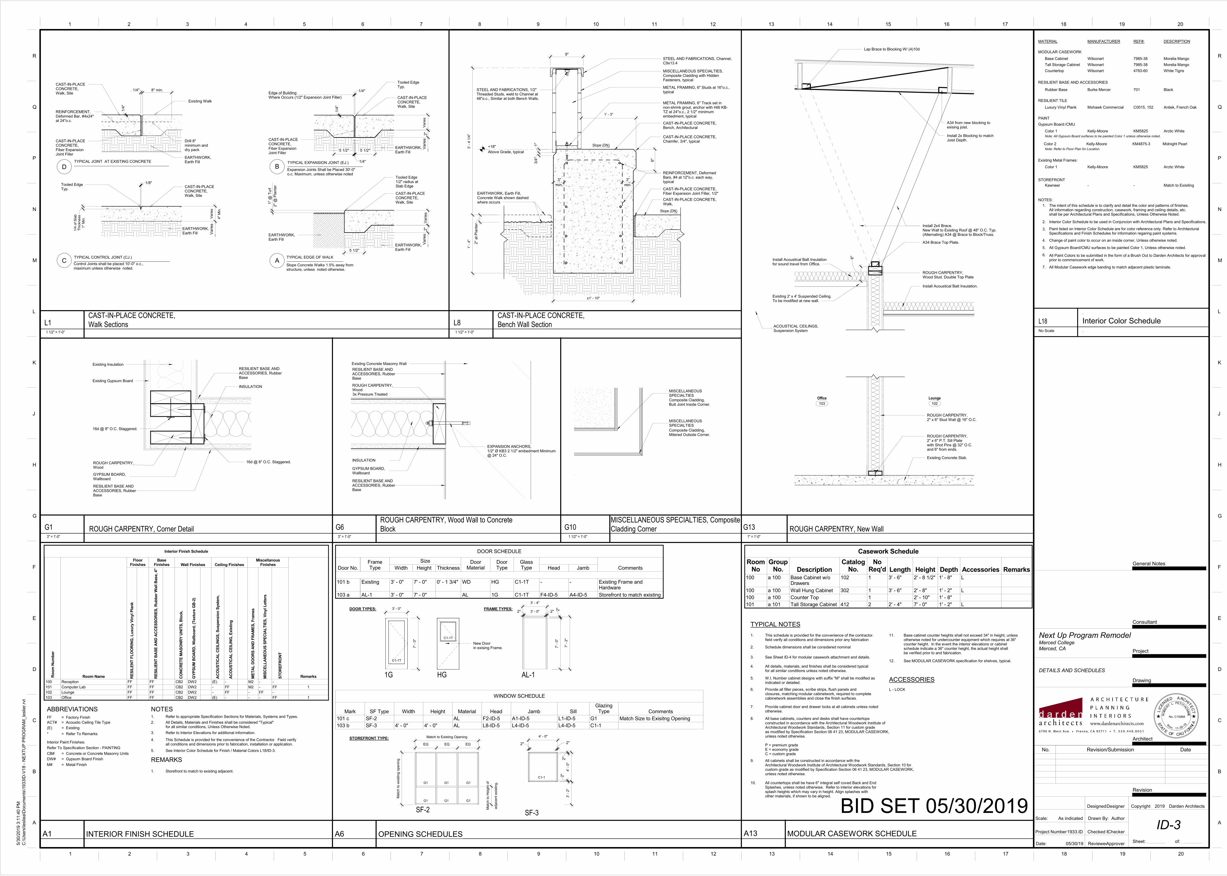
1/4
"
CAST-IN-PLACE CONCRETE, Walk, Site
REINFORCEMENT, Deformed Bar, #4x24" at 24"o.c.
CAST-IN-PLACE CONCRETE, Fiber Expansion Joint Filler
Existing Walk
Drill 8" minimum and dry pack
EARTHWORK, Earth Fill
Tooled EdgeTyp.
1"
Min
.
1/4
of S
lab
Thic
kness
1/8"CAST-IN-PLACE CONCRETE, Walk, Site
EARTHWORK, Earth Fill
4"
Min
.
Varies
Varies
Control Joints shall be placed 10'-0" o.c., maximum unless otherwise noted.
TYPICAL CONTROL JOINT (CJ.)C
D B
A
TYPICAL JOINT AT EXISTING CONCRETE TYPICAL EXPANSION JOINT (EJ.)
TYPICAL EDGE OF WALK
1/4"
CAST-IN-PLACE CONCRETE, Fiber Expansion Joint Filler
CAST-IN-PLACE CONCRETE, Walk, Site
Tooled EdgeTyp.
1/4
"
EARTHWORK, Earth Fill
Varies
2"
Varies
5 1/2"5 1/2"
1/4"
Edge of BuildingWhere Occurs (1/2" Expansion Joint Filler)
Expansion Joints Shall be Placed 30'-0" o.c. Maximum, unless otherwise noted
Slope Concrete Walks 1.5% away from structure, unless noted otherwise.
EARTHWORK, Earth Fill
EARTHWORK, Earth Fill
Tooled Edge1/2" radius at Slab Edge
CAST-IN-PLACE CONCRETE, Walk, Site
5 1/2"
2"
Va
rie
sV
aries
2"
@ P
lan
ter
1"
@ T
urf
. 1/4" 8" min.
CAST-IN-PLACE CONCRETE, Bench, Architectural
REINFORCEMENT, Deformed Bars, #4 at 12"o.c. each way, typical
+18"
Above Grade, typical
CAST-IN-PLACE CONCRETE, Walk,
2"
at
Pla
nte
r
1' -
4"
3' -
4 1
/4"
Slope (DN)
Slope (DN)
CAST-IN-PLACE CONCRETE, Fiber Expansion Joint Filler, 1/2"
min.
3"
min.
3"
CAST-IN-PLACE CONCRETE, Chamfer, 3/4", typical
3/4
"1
"
EARTHWORK, Earth Fill, Concrete Walk shown dashed where occurs
STEEL AND FABRICATIONS, Channel, C9x13.4
METAL FRAMING, 6" Studs at 16"o.c., typical
METAL FRAMING, 6" Track set in non-shrink grout, anchor with Hilti KB-TZ at 24"o.c., 2 1/2" minimum embedment, typical
±1' - 10"
6"
MISCELLANEOUS SPECIALTIES, Composite Cladding with Hidden Fasteners, typical
9"
1' - 3"
STEEL AND FABRICATIONS, 1/2" Threaded Studs, weld to Channel at 48"o.c., Similar at both Bench Walls.
Composite Cladding,Mitered Outside Corner.
Composite Cladding,Butt Joint Inside Corner.
MISCELLANEOUSSPECIALTIES
MISCELLANEOUSSPECIALTIES
1. Refer to appropriate Specification Sections for Materials, Systems and Types.
NOTESFF = Factory Finish
ACT# = Acoustic Ceiling Tile Type
(E) = Existing
* = Refer To Remarks
Interior Paint Finishes:
Refer To Specification Section - PAINTING
CB# = Concrete or Concrete Masonry Units
DW# = Gypsum Board Finish
M# = Metal FinishREMARKS
1. Storefront to match to existing adjacent.
2. All Details, Materials and Finishes shall be considered "Typical"for all similar conditions, Unless Otherwise Noted.
3. Refer to Interior Elevations for additional information.
4. This Schedule is provided for the convenience of the Contractor. Field verifyall conditions and dimensions prior to fabrication, installation or application.
5. See Interior Color Schedule for Finish / Material Colors L18/ID-3.
ABBREVIATIONS
ROUGH CARPENTRY,Wood
GYPSUM BOARD,Wallboard
RESILIENT BASE ANDACCESSORIES, RubberBase
INSULATION
Existing Gypsum Board
Existing InsulationRESILIENT BASE ANDACCESSORIES, RubberBase
16d @ 8" O.C. Staggered.
16d @ 8" O.C. Staggered.
INSULATION
GYPSUM BOARD,Wallboard
ROUGH CARPENTRY,Wood
RESILIENT BASE ANDACCESSORIES, RubberBase
RESILIENT BASE ANDACCESSORIES, RubberBase
Exisitng Concrete Masonry Wall
EXPANSION ANCHORS,1/2" Ø KB3 2 1/2" embedment Minimum@ 24" O.C.
3x Pressure Treated
ROUGH CARPENTRY,Wood Stud. Double Top Plate
Install 2x4 Brace.New Wall to Existing Roof @ 48" O.C. Typ.(Alternating) A34 @ Brace to Block/Truss.
Install Acoustical Batt Insulation.
Install Acoustical Batt Insulation for sound travel from Office.
Existing 2' x 4' Suspended Ceiling.To be modified at new wall.
A34 Brace Top Plate.
Install 2x Blocking to match Joist Depth.
A34 from new blocking to exising joist.
6"
Lap Brace to Blocking W/ (4)10d
ACOUSTICAL CEILINGS,Suspension System
ROUGH CARPENTRY,2" x 6" Stud Wall @ 16" O.C.
ROUGH CARPENTRY,2" x 6" P.T. Sill Platewith Shot Pins @ 32" O.C. and 6" from ends.
Existing Concrete Slab.
Lounge
102
Office
103
3' - 0"
7' -
0"
Match to Existing Opening
Matc
h to e
xis
ting o
penin
g
ad
jace
nt exis
tin
g.
Matc
h to H
eig
ht of
EQ EQ EQ
4' - 0"
4' -
0"
2"
2"
3' -
2"
2"
2"
2" 2"3' - 0"
7' -
2"
2"
7' -
0"
3' - 4"
1. This schedule is provided for the convenience of the contractor.field verify all conditions and dimensions prior any fabrication
12. See MODULAR CASEWORK specification for shelves, typical.
2. Schedule dimensions shall be considered nominal
3. See Sheet ID-4 for modular casework attachment and details.
4. All details, materials, and finishes shall be considered typicalfor all similar conditions unless noted otherwise.
5. W.I. Number cabinet designs with suffix "M" shall be modified asindicated or detailed.
6. Provide all filler pieces, scribe strips, flush panels andclosures, matching modular cabinetwork, required to completecabinetwork assemblies and close the finish surfaces.
7. Provide cabinet door and drawer locks at all cabinets unless notedotherwise.
8. All base cabinets, counters and desks shall have countertopsconstructed in accordance with the Architectural Woodwork Institute ofArchitectural Woodwork Standards, Section 11 for custom gradeas modified by Specification Section 06 41 23, MODULAR CASEWORK,unless noted otherwise.
P = premium gradeE = economy gradeC = custom grade
9. All cabinets shall be constructed in accordance with theArchitectural Woodwork Institute of Architectural Woodwork Standards, Section 10 for custom grade as modified by Specification Section 06 41 23, MODULAR CASEWORK,unless noted otherwise.
10. All countertops shall be have 6" integral self coved Back and EndSplashes, unless noted otherwise. Refer to interior elevations forsplash heights which may vary in height. Align splashes withother materials, if shown to be aligned.
11. Base cabinet counter heights shall not exceed 34" in height, unlessotherwise noted for undercounter equipment which requires at 36"counter height. In the event the interior elevations or cabinetschedule indicate a 36" counter height, the actual height shallbe verified prior to and fabrication.
TYPICAL NOTES
ACCESSORIES
L - LOCK
MATERIAL
L18 Interior Color Schedule
.
No Scale .
MANUFACTURER REF#: DESCRIPTION
MODULAR CASEWORK
Base Cabinet
Tall Storage Cabinet
Wilsonart
Wilsonart
7985-38
7985-38
Morelia Mango
Morelia Mango
Countertop Wilsonart 4783-60 White Tigris
RESILIENT BASE AND ACCESSORIES
Rubber Base Burke Mercer 701 Black
RESILIENT TILE
Luxury Vinyl Plank Mohawk Commercial C0015, 152 Antiek, French Oak
PAINT
Color 1 Kelly-Moore KM5825 Arctic White
Note: All Gypsum Board surfaces to be painted Color 1 unless otherwise noted.
Color 2 Kelly-Moore KM4875-3 Midnight Pearl
Note: Refer to Floor Plan for Location.
Gypsum Board:/CMU
Color 1 Kelly-Moore KM5825 Arctic White
Existing Metal Frames:
STOREFRONT
Kawneer - - Match to Exisiting
NOTES:
1. The intent of this schedule is to clarify and detail the color and patterns of finishes.All information regarding construction, casework, framing and ceiling details, etc.shall be per Architectural Plans and Specifications, Unless Otherwise Noted.
2. Interior Color Schedule to be used in Conjuncion with Architectural Plans and Specifications.
3. Paint listed on Interior Color Schedule are for color reference only. Refer to ArchitecturalSpecifications and Finish Schedules for information regaring paint systems.
4. Change of paint color to occur on an inside corner, Unless otherwise noted.
5. All Gypsum Board/CMU surfaces to be painted Color 1, Unless otherwise noted.
6. All Paint Colors to be submitted in the form of a Brush Out to Darden Architects for approvalprior to commencement of work.
7. All Modular Casework edge banding to match adjacent plastic laminate.
TC
ETI
HCRAES
NE
CIL
D
RO
BE
RTPETITHO
MM
L.
E
No. C15968
AL FORNI
STA
TE
OF C I
A
11 30R
en. --
Scale:
Date:
Checked By:
Reviewed By:
Project Number:
A
B
C
D
E
F
G
H
J
K
L
M
N
P
Q
R
A
B
C
D
E
F
G
H
J
K
L
M
N
P
Q
R
Drawn By:
Designed By:
Drawing
Project
Consultant
1 2 3 4 5 6 7 8 9 10 11 12 13 14 15 16 17 18 19 20
1 2 3 4 5 6 7 8 9 10 11 12 13 14 15 16 17 18 19 20
General Notes
19
Revision
Sheet: of:
Copyright Darden Architects
Architect
BID SET 05/30/2019As indicated
5/3
0/2
019 3
:11:4
0 P
M
C:\U
sers
\leslie
a\D
ocum
ents
\1933ID
-V18 -
NE
XT
UP
PR
OG
RA
M_le
slie
r.rv
t
ID-3
DETAILS AND SCHEDULES
Merced College
Next Up Program Remodel
Checker
Author
05/30/19
1933.ID
Approver
Designer
Merced, CA
2019
1 1/2" = 1'-0"
L1CAST-IN-PLACE CONCRETE,
Walk Sections1 1/2" = 1'-0"
L8CAST-IN-PLACE CONCRETE,
Bench Wall Section
1 1/2" = 1'-0"
G10MISCELLANEOUS SPECIALTIES, Composite
Cladding Corner
Interior Finish Schedule
Ro
om
Nu
mb
er
Room Name
FloorFinishes
BaseFinishes Wall Finishes Ceiling Finishes
MiscellanousFinishes
RemarksRE
SIL
EN
T F
LO
OR
ING
, L
uxu
ry V
inyl P
lan
k
RE
SIL
IEN
T B
AS
E A
ND
AC
CE
SS
OR
IES
, R
ub
ber
Wall B
ase, 4"
CO
NC
RE
TE
MA
SO
NR
Y U
NIT
S, B
lock,
GY
PS
UM
BO
AR
D, W
allb
oard
, (T
extu
re G
B-2
)
AC
OU
ST
ICA
L C
EIL
ING
S, S
usp
en
sio
n S
yste
m,
AC
OU
ST
ICA
L C
EIL
ING
, E
xis
tin
g
ME
TA
L D
OO
RS
AN
D F
RA
ME
S, F
ram
es
MIS
CE
LL
AN
EO
US
SP
EC
IAL
TIE
S, V
inyl L
ett
ers
ST
OR
EF
RO
NT
100 Reception FF FF CB2 DW2 (E) - M2 - -
101 Computer Lab FF FF CB2 DW2 - FF M2 - FF 1
102 Lounge FF FF CB2 DW2 - FF - FF -
103 Office FF FF CB2 DW2 (E) - - - FF 1
A1 INTERIOR FINISH SCHEDULE
3" = 1'-0"
G1 ROUGH CARPENTRY, Corner Detail3" = 1'-0"
G6ROUGH CARPENTRY, Wood Wall to Concrete
Block1" = 1'-0"
G13 ROUGH CARPENTRY, New Wall
DOOR SCHEDULE
Door No.FrameType
Size DoorMaterial
DoorType
GlassType CommentsWidth Height Thickness Head Jamb
101 b Existing 3' - 0" 7' - 0" 0' - 1 3/4" WD HG C1-1T - - Existing Frame andHardware
103 a AL-1 3' - 0" 7' - 0" AL 1G C1-1T F4-ID-5 A4-ID-5 Storefront to match existing
WINDOW SCHEDULE
Mark SF Type Width Height Material Head Jamb SillGlazing
Type Comments
101 c SF-2 AL F2-ID-5 A1-ID-5 L1-ID-5 G1 Match Size to Exisitng Opening
103 b SF-3 4' - 0" 4' - 0" AL L8-ID-5 L4-ID-5 L4-ID-5 C1-1
HG1G
SF-2 SF-3
AL-1
DOOR TYPES: FRAME TYPES:
STOREFRONT TYPE:
A6 OPENING SCHEDULES
New Doorin exising Frame.
Casework Schedule
RoomNo
GroupNo. Description
CatalogNo.
NoReq'd Length Height Depth Accessories Remarks
100 a 100 Base Cabinet w/oDrawers
102 1 3' - 6" 2' - 8 1/2" 1' - 8" L
100 a 100 Wall Hung Cabinet 302 1 3' - 6" 2' - 8" 1' - 2" L
100 a 100 Counter Top 1 2' - 10" 1' - 8"
101 a 101 Tall Storage Cabinet 412 2 2' - 4" 7' - 0" 1' - 2" L
A13 MODULAR CASEWORK SCHEDULE
C1-1T
C1-1T
G1 G1 G1
G1 G1 G1
C1-1
No. Revision/Submission Date
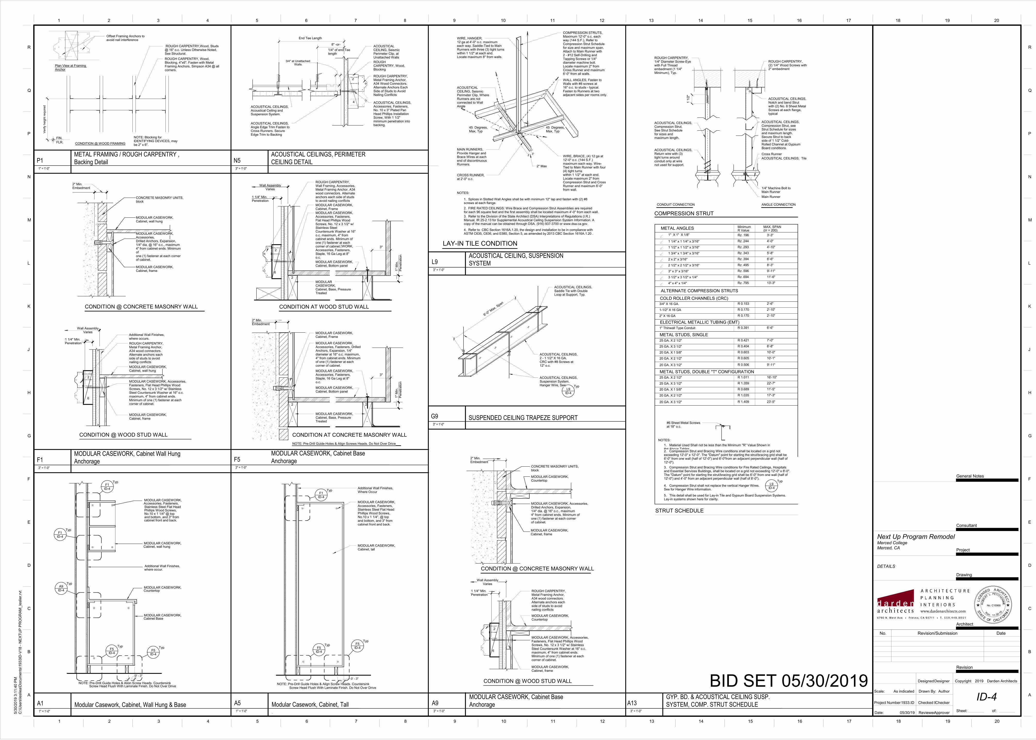
MODULAR CASEWORK,
MODULAR CASEWORK,
MODULAR CASEWORK,
Accessories, Fasteners,MODULAR CASEWORK,
Countertop
Cabinet Base
Cabinet, wall hung
Phillips Wood Screws,
and bottom, and 3" from
Additional Wall Finishes,where occur.
cabinet front and back.
Stainless Steel Flat Head
No.10 x 1 1/4" @ top
NOTE: Pre-Drill Guide Holes & Align Screw Heads. CountersinkScrew Head Flush With Laminate Finish. Do Not Over Drive
ID-4F1
Typ
ID-4F1
Typ
ID-4A9
Typ
ID-4F5
Typ
ID-4F5
Typ
0' - 3"
ROUGH CARPENTRY,Metal Framing Anchor,A34 wood connectors.Alternate anchors eachside of studs to avoidnailing conflicts
CONDITION @ WOOD STUD WALL
MODULAR CASEWORK,Cabinet, wall hung
Wall AssemblyVaries
Additional Wall Finishes,where occurs.1 1/4" Min.
Penetration
MODULAR CASEWORK, Accessories, Fasteners, Flat Head Phillips Wood Screws, No. 12 x 3 1/2" w/ Stainless Steel Countersunk Washer at 16" o.c. maximum, 4" from cabinet ends. Minimum of one (1) fastener at each corner of cabinet.
2
6
MODULAR CASEWORK,Cabinet, frame
CONDITION @ CONCRETE MASONRY WALL
MODULAR CASEWORK,Cabinet, wall hung
2" Min.Embedment
CONCRETE MASONRY UNITS,block
MODULAR CASEWORK, Accessories,Drilled Anchors, Expansion,1/4" dia. @ 16" o.c., maximum4" from cabinet ends. Minimum ofone (1) fastener at each cornerof cabinet.
MODULAR CASEWORK,Cabinet, frame
ROUGH CARPENTRY, Wall Framing, Accessories, Metal Framing Anchor, A34 wood connectors. Alternate anchors each side of studs to avoid nailing conflicts
CONDITION AT WOOD STUD WALL
CONDITION AT CONCRETE MASONRY WALL
MODULAR CASEWORK, Cabinet, Bottom panel
MODULAR CASEWORK, Cabinet, Frame
MODULAR CASEWORK,Cabinet, Bottom panel
NOTE: Pre-Drill Guide Holes & Align Screws Heads. Do Not Over Drive
-
2
-
2
MODULAR CASEWORK, Accessories, Fasteners, Staple, 16 Ga Leg at 8" o.c.
MODULAR CASEWORK, Cabinet, Frame
-
2 2
-
Wall AssemblyVaries
MODULAR CASEWORK, Accessories, Fasteners, Staple, 16 Ga Leg at 8" o.c.
1 1/4" Min.Penetration
2" Min.Embedment
MODULAR CASEWORK,Cabinet, Base, Pressure Treated
1"
Min
.P
enetr
ation
MODULAR CASEWORK,Cabinet, Base, Pressure Treated
2
6
MODULAR CASEWORK, Accessories, Fasteners, Drilled Anchors, Expansion, 1/4" diameter at 16" o.c. maximum, 4" from cabinet ends. Minimum of one (1) fastener at each corner of cabinet.
1"
Min
.P
enetr
ation
3"
3"
MODULAR CASEWORK, Accessories, Fasteners, Flat Head Phillips Wood Screws, No. 12 x 3 1/2" w/ Stainless SteelCountersunk Washer at 16" o.c. maximum, 4" from cabinet ends. Minimum of one (1) fastener at each corner of cabinet.
.
MODULAR CASEWORK,Cabinet, tall
Additional Wall Finishes,Where Occur
MODULAR CASEWORK,Accessories, Fasteners,Stainless Steel Flat HeadPhillips Wood Screws,No.10 x 1 1/4", @ topand bottom, and 3" fromcabinet front and back.
NOTE: Pre-Drill Guide Holes & Align Screw Heads. CountersinkScrew Head Flush With Laminate Finish. Do Not Over Drive
ID-4
F1Typ
ID-4
F5Typ
ID-4
F5Typ
0' - 3"
ROUGH CARPENTRY,Metal Framing Anchor,A34 wood connectors.Alternate anchors eachside of studs to avoidnailing conflicts
CONDITION @ WOOD STUD WALL
Wall AssemblyVaries
1 1/4" Min.Penetration
MODULAR CASEWORK,Countertop
2
6
MODULAR CASEWORK,Cabinet, frame
CONDITION @ CONCRETE MASONRY WALL
2" Min.Embedment
CONCRETE MASONRY UNITS,block
MODULAR CASEWORK,Countertop
MODULAR CASEWORK, Accessories,Drilled Anchors, Expansion,1/4" dia. @ 16" o.c., maximum4" from cabinet ends. Minimum ofone (1) fastener at each cornerof cabinet.
MODULAR CASEWORK,Cabinet, frame
MODULAR CASEWORK, Accessories, Fasteners, Flat Head Phillips Wood Screws, No. 12 x 3 1/2" w/ Stainless Steel Countersunk Washer at 16" o.c. maximum, 4" from cabinet ends. Minimum of one (1) fastener at each corner of cabinet.
CONDITION @ WOOD FRAMING
ROUGH CARPENTRY,Wood, Studs @ 16" o.c. Unless Otherwise Noted, See Structural.
ROUGH CARPENTRY, Wood, Blocking, 4"x6". Fasten with Metal Framing Anchors, Simpson A34 @ all corners.
NOTE: Blocking for IDENTIFYING DEVICES, may be 2" x 6".
FIN.
FLR.
Verify
heig
ht re
quired
Offset Framing Anchors toavoid nail interference
Plan View at Framing Anchor
2
4
ROUGH CARPENTRY, Metal Framing Anchor, A34 Wood Connectors. Alternate Anchors Each Side of Studs to Avoid Nailing Conflicts
ACOUSTICAL CEILINGS, Accessories, Fasteners, No. 10 x 3" Plated Pan Head Phillips Installation Screw, With 1 1/2" minimum penetration into backing.
ROUGH CARPENTRY, Wood, Blocking
ACOUSTICAL CEILINGS,Acoustical Ceiling andSuspension System.
End Tee Length
8" -or-
1/4" of end Teelength
Walls3/4" at Unattached
ACOUSTICAL CEILING, Seismic Perimeter Clip, at Unattached Walls
ACOUSTICAL CEILINGS, Angle Edge Trim Fasten to Cross Runners. Secure Edge Trim to Backing
LAY-IN TILE CONDITION
NOTES:
1. Splices in Slotted Wall Angles shall be with minimum 12" lap and fasten with (2) #8 screws at each flange.
2. FIRE RATED CEILINGS: Wire Brace and Compression Strut Assemblies are requiredfor each 96 square feet and the first assembly shall be located maximum 4'-0" from each wall.
WIRE, HANGER, 12 ga at 4'-0" o.c. maximum each way. Saddle-Tied to Main Runners with three (3) tight turns within 1 1/2" at each end. Locate maximum 8" from walls.
WIRE, BRACE, (4) 12 ga at 12'-0" o.c. (144 S.F.) maximum each way. Wire-Tied to Main Runner with four (4) tight turnswithin 1 1/2" at each end. Locate maximum 2" from Compression Strut and Cross Runner and maximum 6'-0" from wall.
MAIN RUNNERS, Provide Hanger andBrace Wires at each end of discontinuous Runners.
WALL ANGLES, Fasten toWalls with #8 screws at16" o.c. to studs - typical.Fasten to Runners at twoadjacent sides per rooms only.
COMPRESSION STRUTS,Maximum 12'-0" o.c. eachway (144 S.F.), Refer toCompression Strut Schedulefor size and maximum span.Attach to Main Runner with2 - #12 Self-Drilling andTapping Screws or 1/4"diameter machine bolt.Locate maximum 2" fromCross Runner and maximum6'-0" from all walls.
CROSS RUNNER,at 2'-0" o.c.
ACOUSTICAL CEILING, Seismic Perimeter Clip, Where Runners are not connected to Wall Angle
45 Degrees, Max, Typ
45 Degrees, Max, Typ
2" Max
3. Refer to the Division of the State Architect (DSA) Interpretations of Regulations (I.R.)Manual, IR 25-2.13 for Supplemental Acoustical Ceiling Suspension System Information. A copy of the manual can be obtained through DSA. (916) 937-3700 or www.dsa.ca.gov.
4. Refer to CBC Section 1616A.1.20, the design and installation to be in compliance with ASTM C635, C636, and E580, Section 5, as amended by 2013 CBC Section 1616A.1.20 .
METAL STUDS, SINGLE
METAL STUDS, DOUBLE "T" CONFIGURATION
COLD ROLLER CHANNELS (CRC)
ELECTRICAL METALLIC TUBING (EMT)
STRUT SCHEDULE
METAL ANGLES
ALTERNATE COMPRESSION STRUTS
COMPRESSION STRUT
MAX. SPAN(l/r = 200)
1" X 1" X 1/8"
1 1/4" x 1 1/4" x 3/16"
1 1/2" x 1 1/2" x 3/16"
1 3/4" x 1 3/4" x 3/16"
2 x 2" x 3/16"
2 1/2" x 2 1/2" x 3/16"
3" x 3" x 3/16"
3 1/2" x 3 1/2" x 1/4"
4" x 4" x 1/4"
3'-3"
4'-0"
4'-10"
5'-8"
6'-6"
8'-3"
9'-11"
11'-6"
13'-3"
3/4" X 16 GA. 2'-6"
1-1/2" X 16 GA 2'-10"
2" X 16 GA 2'-10"
1" Thinwall Type Conduit 6'-6"
R ValueMinimum
Rz .196
Rz .244
Rz .293
Rz .343
Rz .394
Rz .495
Rz .596
Rz .694
Rz .795
R 0.153
R 0.170
R 0.170
R 0.391
1. Material Used Shall not be less than the Minimum "R" Value Shown inthe Above Tables2. Compression Strut and Bracing Wire conditions shall be located on a grid not exceeding 12'-0" x 12'-0". The "Datum" point for starting the strut/bracing grid shall be 6'-0" from one wall (half of 12'-0") and 6'-0"from an adjacent perpendicular wall (half of 12'-0").
NOTES:
4. Compression Strut shall not replace the vertical Hanger Wires. See for Hanger Wire information.
5. This detail shall be used for Lay-in Tile and Gypsum Board Suspension Systems. Lay-in systems shown here for clarity.
25 GA. X 2 1/2" 7'-0"R 0.421
25 GA. X 3 1/2" 6'-8"R 0.404
20 GA. X 1 5/8" 10'-0"R 0.603
20 GA. X 2 1/2" 10'-1"R 0.605
20 GA. X 3 1/2" R 0.506 9'-11"
25 GA. X 2 1/2" 16'-10"R 1.011
25 GA. X 3 1/2" 22'-7"R 1.359
20 GA. X 1 5/8" 11'-5"R 0.689
20 GA. X 2 1/2" 17'-3"R 1.035
20 GA. X 3 1/2" R 1.409 23'-5"
#6 Sheet Metal Screwsat 18" o.c.
3. Compression Strut and Bracing Wire conditions for Fire Rated Ceilings, Hospitals and Essential Services Buildings, shall be located on a grid not exceeding 12'-0" x 8'-0". The "Datum" point for starting the strut/bracing grid shall be 6'-0" from one wall (half of 12'-0") and 4'-0" from an adjacent perpendicular wall (half of 8'-0").
ID-4L9
Typ
CONDUIT CONNECTION ANGLE CONNECTION
ACOUSTICAL CEILINGS,Notch and bend Strutwith (2) No. 8 Sheet MetalScrews at each flange,typical
1/4" Machine Bolt toMain Runner
Main Runner
Cross Runner
ACOUSTICAL CEILINGS, Tile
ACOUSTICAL CEILINGS,Compression Strut, seeStrut Schedule for sizesand maximum length.Secure Strut to backside of 1 1/2" Cold-Rolled Channel at GypsumBoard conditions.
ACOUSTICAL CEILINGS,Compression Strut,See Strut Schedulefor sizes and maximum length.
ACOUSTICAL CEILINGS,Return wire with (3)tight turns aroundconduit only at wirenot used for support.
ROUGH CARPENTRY,(2) 1/4" Wood Screws with2" embedment
1 1
/2"
ROUGH CARPENTRY, 1/4" Diameter Screw-Eye with Full Thread embedment (1 1/4" Minimum), Typ.
ID-4
L9Typ
6'-0" M
ax. Span
ACOUSTICAL CEILINGS,2 - 1 1/2" X 16 GA.CRC with #8 Screws at12" o.c.
ACOUSTICAL CEILINGS,Suspension System,Hanger Wire, See
ACOUSTICAL CEILINGS,Saddle Tie with Double Loop at Support, Typ.
TC
ETI
HCRAES
NE
CIL
D
RO
BE
RTPETITHO
MM
L.
E
No. C15968
AL FORNI
STA
TE
OF C I
A
11 30R
en. --
Scale:
Date:
Checked By:
Reviewed By:
Project Number:
A
B
C
D
E
F
G
H
J
K
L
M
N
P
Q
R
A
B
C
D
E
F
G
H
J
K
L
M
N
P
Q
R
Drawn By:
Designed By:
Drawing
Project
Consultant
1 2 3 4 5 6 7 8 9 10 11 12 13 14 15 16 17 18 19 20
1 2 3 4 5 6 7 8 9 10 11 12 13 14 15 16 17 18 19 20
General Notes
19
Revision
Sheet: of:
Copyright Darden Architects
Architect
BID SET 05/30/2019As indicated
5/3
0/2
019 3
:11:4
0 P
M
C:\U
sers
\leslie
a\D
ocum
ents
\1933ID
-V18 -
NE
XT
UP
PR
OG
RA
M_le
slie
r.rv
t
ID-4
DETAILS
Merced College
Next Up Program Remodel
Checker
Author
05/30/19
1933.ID
Approver
Designer
Merced, CA
2019
1" = 1'-0"
A1 Modular Casework, Cabinet, Wall Hung & Base
3" = 1'-0"
F1MODULAR CASEWORK, Cabinet Wall Hung
Anchorage3" = 1'-0"
F5MODULAR CASEWORK, Cabinet Base
Anchorage
1" = 1'-0"
A5 Modular Casework, Cabinet, Tall3" = 1'-0"
A9MODULAR CASEWORK, Cabinet Base
Anchorage
1" = 1'-0"
P1METAL FRAMING / ROUGH CARPENTRY ,
Backing Detail3" = 1'-0"
N5ACOUSTICAL CEILINGS, PERIMETER
CEILING DETAIL
3" = 1'-0"
L9ACOUSTICAL CEILING, SUSPENSION
SYSTEM
3" = 1'-0"
A13GYP. BD. & ACOUSTICAL CEILING SUSP.
SYSTEM, COMP. STRUT SCHEDULE
3" = 1'-0"
G9 SUSPENDED CEILING TRAPEZE SUPPORT
No. Revision/Submission Date
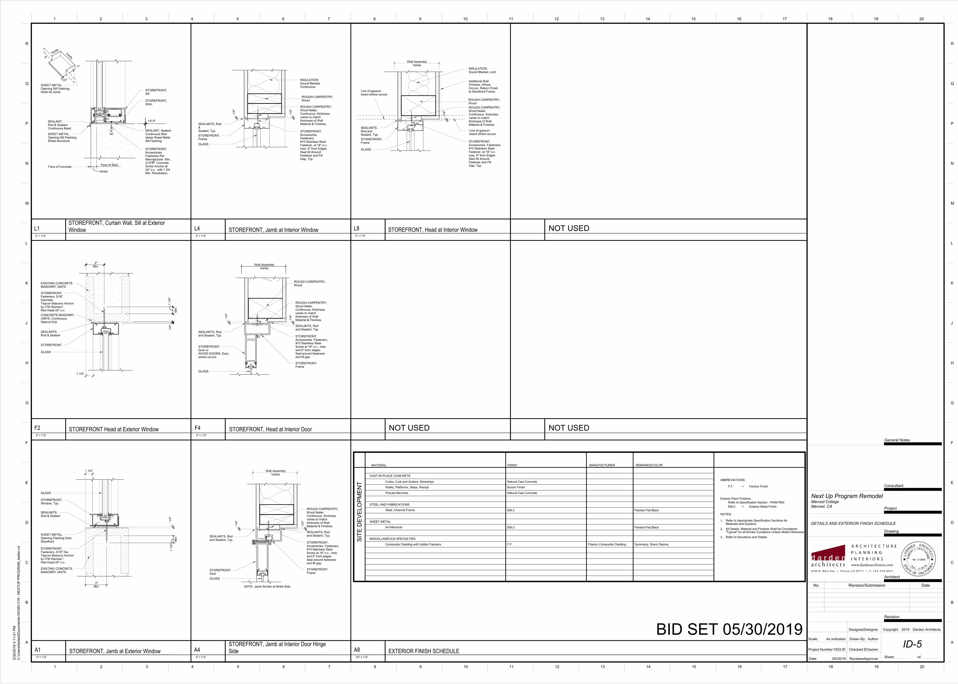
4"
+0'-0"
Face of Stud
SEALANT,Rod & Sealant,Continuous Bead
STOREFRONT,Sill
STOREFRONT,Shim
SHEET METAL,Opening Sill Flashing,Sheet Aluminum
STOREFRONT,Accessories,Fasteners PerManufacturer. Min.3/16" ConcreteScrew Anchor at24" o.c., with 1 3/4Min. Penetration.
SEALANT, SealantContinuous Bedbelow Sheet MetalSill Flashing.
Face of Concrete
VerifyVerify
1""
1/2"
SHEET METAL,Opening Sill Flashing,Weld All Joints
Varies
2"Min.
1 1
/4"
1/4
"
STOREFRONT,Fasteners, 3/16" DiameterTapcon Masonry Anchorby ITW Ramset /Red Head 24" o.c.
STOREFRONT
GLASS
SEALANTS,Rod & Sealant
EXISTING CONCRETE MASONRY UNITS
Min
.
CONCRETE MASONRYUNITS, Continuous,Sawcut Drip
1 1/4"
2"Min.
1 1
/4"
GLASS
SEALANTS,Rod & Sealant
SHEET METAL,Opening Flashing Dam,Storefront
STOREFRONT,Window, Typ.
EXISTING CONCRETE MASONRY UNITS
STOREFRONT,Fasteners, 3/16" DiaTapcon Masonry Anchorby ITW Ramset /Red Head 24" o.c.
Min
.
1/4
"
1 1/4"
NOTE: Jamb Similar at Strike Side
Wall AssemblyVaries
STOREFRONT,Door
GLASS
SEALANTS, Rodand Sealant, Typ.
ROUGH CARPENTRY,Wood Nailer,Continuous, thicknessvaries to matchthickness of WallMaterial & Finishes.
.STOREFRONT,Accessories, Fasteners,#10 Stainless SteelScrew at 16" o.c., max.and 6" from edges,Seal around fastenersand fill gap.
.STOREFRONT,Frame
SEALANTS, Rodand Sealant, Typ.
1/4
"
1/4
"
.
INSULATIONSound Blanket,Continuous
GLASS
ROUGH CARPENTRY,Wood Nailer,Continuous, thicknessvaries to matchthickness of WallMaterial & Finishes.
STOREFRONT,Accessories, Fasteners,#10 Stainless SteelFastener, at 16" o.c.max. 6" from EdgesSeal All AroundFastener and FillGap, Typ.
STOREFRONT,Frame
SEALANTS, Rod &Sealant, Typ.
1/4
"
1/4
"
ROUGH CARPENTRY,Wood
Wall AssemblyVaries
STOREFRONT,Door orWOOD DOORS, Door, where occurs
GLASS
SEALANTS, Rodand Sealant, Typ.
ROUGH CARPENTRY,Wood Nailer,Continuous, thicknessvaries to matchthickness of WallMaterial & Finishes.
.STOREFRONT,Accessories, Fasteners,#10 Stainless SteelScrew at 16" o.c., max.and 6" from edges,Seal around fastenersand fill gap.
.STOREFRONT,Frame
SEALANTS, Rodand Sealant, Typ.
1/4
"
1/4
"
ROUGH CARPENTRY,Wood
Wall AssemblyVaries
GLASS
STOREFRONT,Frame
Additional WallFinishes, WhereOccurs. Return Finishto Storefront Frame.
ROUGH CARPENTRY,Wood Nailer,Continuous, thicknessvaries to matchthickness of WallMaterial & Finishes.
STOREFRONT,Accessories, Fasteners,#10 Stainless SteelFastener, at 16" o.c.max. 6" from EdgesSeal All AroundFastener and FillGap, Typ.
SEALANTS, Rod and Sealant, Typ.
1/4
"
Line of gypsumboard where occurs
Line of gypsumboard where occurs
INSULATION,Sound Blanket, cont.
ROUGH CARPENTRY,Wood
ABBREVIATIONS:
NOTES:
SIT
E D
EV
ELO
PM
EN
T
CAST-IN-PLACE CONCRETE
Natural Cast Concrete
Steel, Channel Frame EM-2
EM-2 Exterior Metal Finish=
1.
2."Typical" for all Similar Conditions Unless Noted Otherwise
Refer to Appropriate Specification Sections for
All Details. Material and Finishes Shall be Considered
F.F. Factory Finish=
Materials and Systems
3. Refer to Elevations and Details
Exterior Paint Finishes:
Refer to Specification Section - PAINTING
MATERIAL FINISH REMARKS/COLOR
Precast Benches Natural Cast Concrete
Walks, Platforms, Steps, Ramps Broom Finish
Curbs, Curb and Gutters, Mowstrips,
STEEL AND FABRICATIONS
MISCELLANEOUS SPECIALTIES
Painted Flat Black
MANUFACTURER
Architectural EM-2
SHEET METAL
Painted Flat Black
Composite Cladding with hidden Fastners F.F. Symmetry, Warm SiennaFiberon Composite Cladding
TC
ETI
HCRAES
NE
CIL
D
RO
BE
RTPETITHO
MM
L.
E
No. C15968
AL FORNI
STA
TE
OF C I
A
11 30R
en. --
Scale:
Date:
Checked By:
Reviewed By:
Project Number:
A
B
C
D
E
F
G
H
J
K
L
M
N
P
Q
R
A
B
C
D
E
F
G
H
J
K
L
M
N
P
Q
R
Drawn By:
Designed By:
Drawing
Project
Consultant
1 2 3 4 5 6 7 8 9 10 11 12 13 14 15 16 17 18 19 20
1 2 3 4 5 6 7 8 9 10 11 12 13 14 15 16 17 18 19 20
General Notes
19
Revision
Sheet: of:
Copyright Darden Architects
Architect
BID SET 05/30/2019As indicated
5/3
0/2
019 3
:11:4
1 P
M
C:\U
sers
\leslie
a\D
ocum
ents
\1933ID
-V18 -
NE
XT
UP
PR
OG
RA
M_le
slie
r.rv
t
ID-5
DETAILS AND EXTERIOR FINISH SCHEDULE
Merced College
Next Up Program Remodel
Checker
Author
05/30/19
1933.ID
Approver
Designer
Merced, CA
2019
3" = 1'-0"
L1STOREFRONT, Curtain Wall, Sill at Exterior
Window
3" = 1'-0"
F2 STOREFRONT Head at Exterior Window
3" = 1'-0"
A1 STOREFRONT, Jamb at Exterior Window3" = 1'-0"
A4STOREFRONT, Jamb at Interior Door Hinge
Side
3" = 1'-0"
L4 STOREFRONT, Jamb at Interior Window
3" = 1'-0"
F4 STOREFRONT, Head at Interior Door
3" = 1'-0"
L8 STOREFRONT, Head at Interior Window
1/4" = 1'-0"
A8 EXTERIOR FINISH SCHEDULE
NOT USED
NOT USEDNOT USED
No. Revision/Submission Date