Embed Size (px)
Citation preview
8/13/2019 Mesh-Intro 14.0 L-06 Local Mesh Controls
http://slidepdf.com/reader/full/mesh-intro-140-l-06-local-mesh-controls 1/32
© 2011 ANSYS, Inc. December 27, 20111 Release 14.0
14. 0 Release
Introduction to ANSYS
Meshing
Lecture 6
Local Mesh Controls
8/13/2019 Mesh-Intro 14.0 L-06 Local Mesh Controls
http://slidepdf.com/reader/full/mesh-intro-140-l-06-local-mesh-controls 2/32
© 2011 ANSYS, Inc. December 27, 20112 Release 14.0
What you will learn from this presentation
• Various local mesh settings (Mesh sizing, Refinement, Match
control, Inflation, etc)
• How to apply local controls?
• Effect of
local
controls
on
mesh
Local Mesh Controls
8/13/2019 Mesh-Intro 14.0 L-06 Local Mesh Controls
http://slidepdf.com/reader/full/mesh-intro-140-l-06-local-mesh-controls 3/32
© 2011 ANSYS, Inc. December 27, 20113 Release 14.0
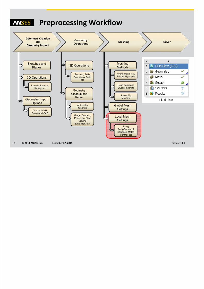
Preprocessing Workflow
Sketches and
Planes
Geometry Import
Options
3D Operations
Direct CAD/Bi-Directional CAD
Geometry
Cleanup and
Repair
Automatic
Cleanup
Merge, Connect,
Projection, Flow
Volume
Extraction, etc
Extrude, Revolve,
Sweep, etc
3D Operations
Boolean, Body
Operations, Split,
etc
Meshing
Methods
Hybrid Mesh: Tet,
Prisms, Pyramids
Hexa Dominant,
Sweep meshing
Global Mesh
Settings
Local Mesh
Settings
Sizing,
Body/Sphere of
Influence, Match
Control, etc
Geometry Creation
OR
Geometry Import
Geometry
Operations Meshing Solver
Assembly
Meshing

8/13/2019 Mesh-Intro 14.0 L-06 Local Mesh Controls
http://slidepdf.com/reader/full/mesh-intro-140-l-06-local-mesh-controls 4/32
© 2011 ANSYS, Inc. December 27, 20114 Release 14.0
Meshing Process in ANSYS Meshing

8/13/2019 Mesh-Intro 14.0 L-06 Local Mesh Controls
http://slidepdf.com/reader/full/mesh-intro-140-l-06-local-mesh-controls 5/32
© 2011 ANSYS, Inc. December 27, 20115 Release 14.0
Local Mesh ControlsControl the mesh locally
• Depends on the “Mesh Method” used
Local Mesh Controls are:
• Sizing
– For Vertex,
Edge,
Face
and
Body
• Contact Sizing
– For Edge and face
• Refinement
– For Vertex, Edge and Face
• Mapped Face
Meshing
– For Face
• Match Control
– For Edge and Face
• Pinch
– For Vertex
and
Edge
• Inflation
– For Edge and Face
Only Sizing and Inflation local controls are
available
for
CutCell meshing
The latest control added on a particular entity
overrides any prior controls
Non-CutCell meshing local controls
CutCell meshing local controls
8/13/2019 Mesh-Intro 14.0 L-06 Local Mesh Controls
http://slidepdf.com/reader/full/mesh-intro-140-l-06-local-mesh-controls 6/32
© 2011 ANSYS, Inc. December 27, 20116 Release 14.0
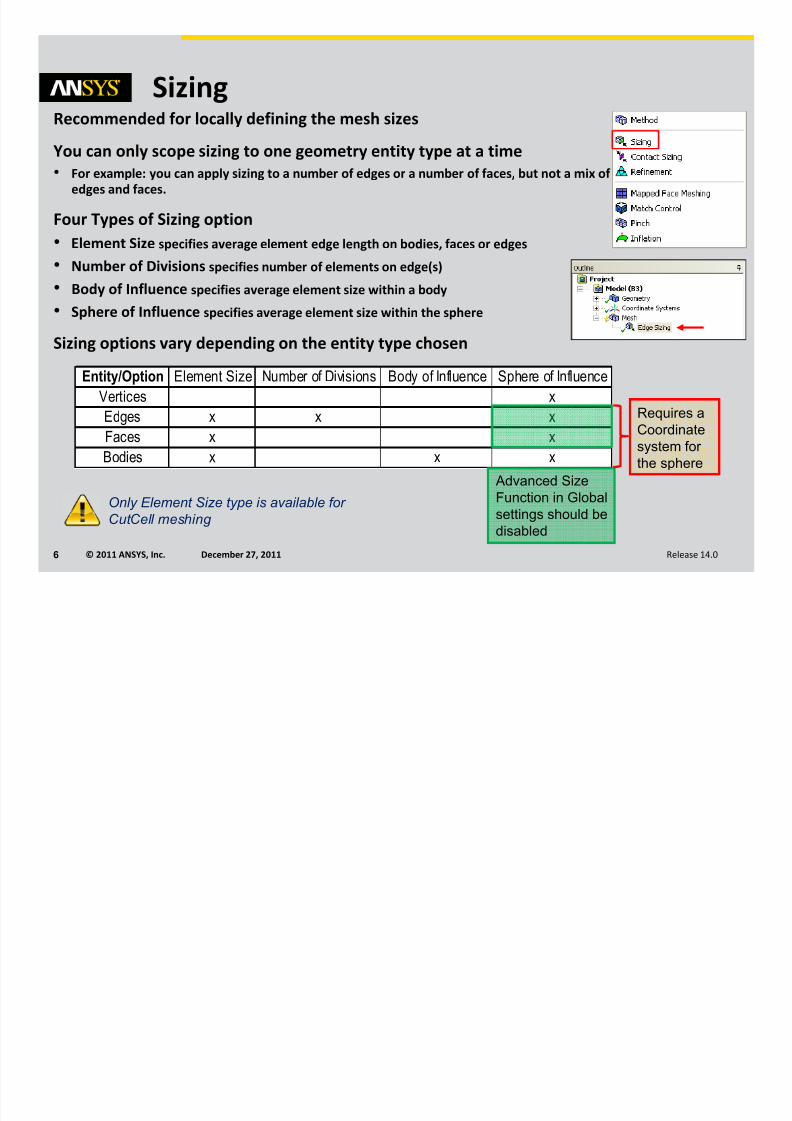
SizingRecommended for locally defining the mesh sizes
You can only scope sizing to one geometry entity type at a time
• For example: you can apply sizing to a number of edges or a number of faces, but not a mix of edges and faces.
Four Types
of
Sizing
option
• Element Size specifies average element edge length on bodies, faces or edges
• Number of Divisions specifies number of elements on edge(s)
• Body of Influence specifies average element size within a body
• Sphere of Influence specifies average element size within the sphere
Sizing options vary depending on the entity type chosen
Entity/Option Element Size Number of Divisions Body of Influence Sphere of Influence
Vertices x
Edges x x x
Faces x x
Bodies x x x
Advanced Size
Function in Global
settings should be
disabled
Requires a
Coordinatesystem for
the sphere
Only Element Size type is available for
CutCell meshing

8/13/2019 Mesh-Intro 14.0 L-06 Local Mesh Controls
http://slidepdf.com/reader/full/mesh-intro-140-l-06-local-mesh-controls 7/32
© 2011 ANSYS, Inc. December 27, 20117 Release 14.0
Sizing : Edges
Edge meshed with constant
element size of 60mm
Edge meshed with 10
elements
Sizing Type: Element Size
Sizing Type: Number of Divisions
The Curvature Normal Angle and/or the Growth Rate
maybe not displayed depending on the ASF used

8/13/2019 Mesh-Intro 14.0 L-06 Local Mesh Controls
http://slidepdf.com/reader/full/mesh-intro-140-l-06-local-mesh-controls 8/32
© 2011 ANSYS, Inc. December 27, 20118 Release 14.0
Sizing : Edges (Contd…)Bias Type and Bias Factor
Specify the grading scheme and factor
• Bias Type: grading of elements towards one end, both ends, or the center
• Bias Factor: is the ratio of the largest element to the smallest element
8/13/2019 Mesh-Intro 14.0 L-06 Local Mesh Controls
http://slidepdf.com/reader/full/mesh-intro-140-l-06-local-mesh-controls 9/32
© 2011 ANSYS, Inc. December 27, 20119 Release 14.0
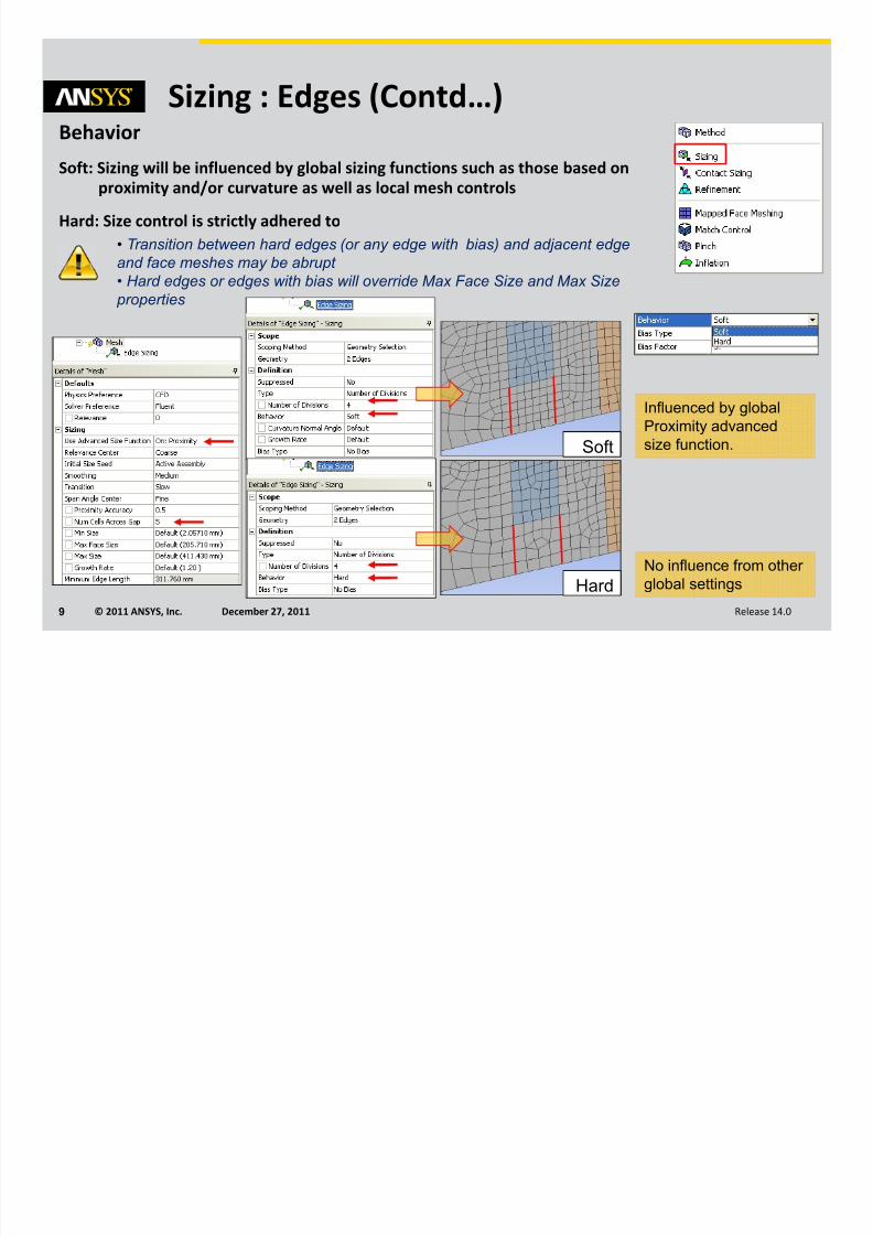
Sizing : Edges (Contd…)Behavior
Soft: Sizing will be influenced by global sizing functions such as those based on
proximity and/or curvature as well as local mesh controls
Hard: Size control is strictly adhered to
Influenced by global
Proximity advanced
size function.Soft
Hard
No influence from other
global settings
• Transition between hard edges (or any edge with bias) and adjacent edge
and face meshes may be abrupt
• Hard edges or edges with bias will override Max Face Size and Max Size
properties

8/13/2019 Mesh-Intro 14.0 L-06 Local Mesh Controls
http://slidepdf.com/reader/full/mesh-intro-140-l-06-local-mesh-controls 10/32
© 2011 ANSYS, Inc. December 27, 201110 Release 14.0
Element Size
Defines the maximum element size on the face
Face meshed with
constant element
size
Sizing : Faces
Edge curvature is
resolved

8/13/2019 Mesh-Intro 14.0 L-06 Local Mesh Controls
http://slidepdf.com/reader/full/mesh-intro-140-l-06-local-mesh-controls 11/32
© 2011 ANSYS, Inc. December 27, 201111 Release 14.0
Element Size
Defines the maximum cell size on the Body
Sizing : Body (volume)
Body meshed with max
cell size defined
Without
body sizing
With body
sizing
Without
body sizing
With body
sizing
Tetrahedron patch
conforming mesh
CutCell
mesh
8/13/2019 Mesh-Intro 14.0 L-06 Local Mesh Controls
http://slidepdf.com/reader/full/mesh-intro-140-l-06-local-mesh-controls 12/32
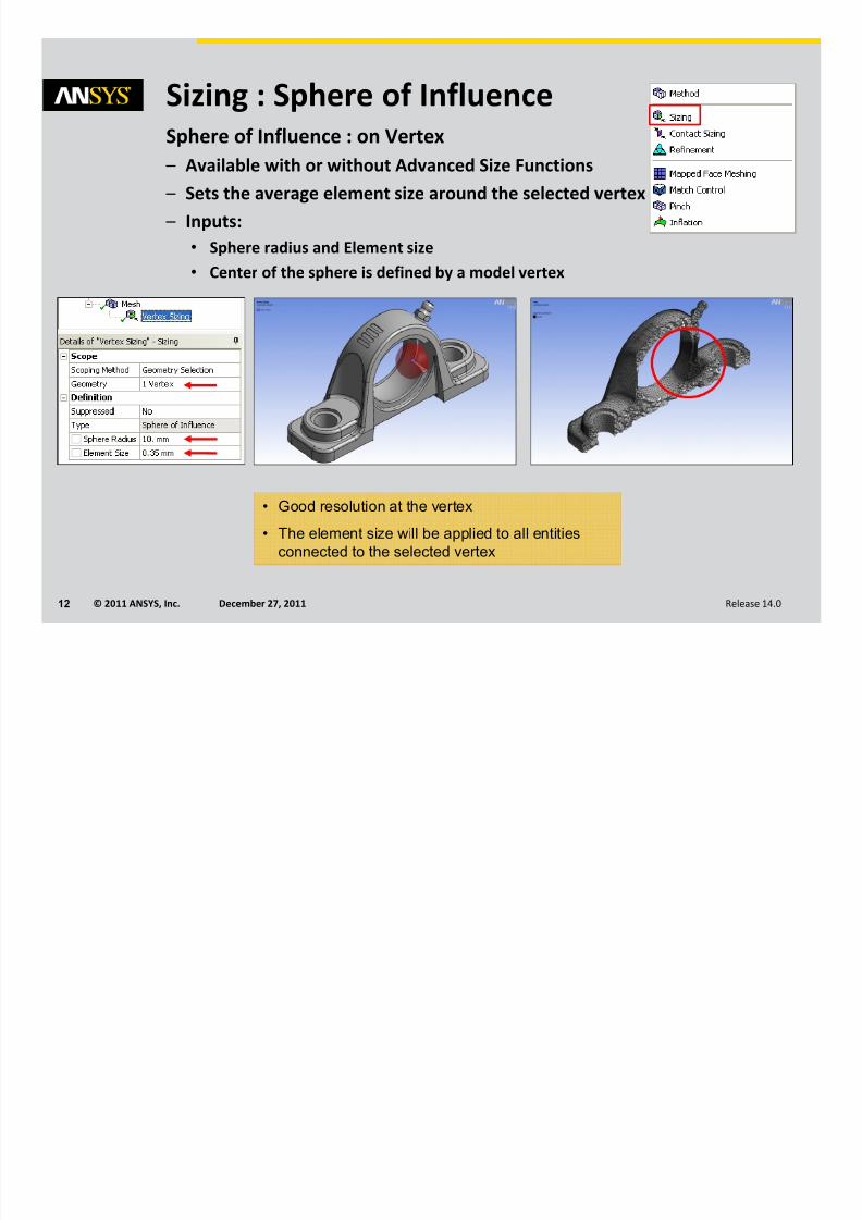
© 2011 ANSYS, Inc. December 27, 201112 Release 14.0
Sphere of Influence : on Vertex
– Available with or without Advanced Size Functions
– Sets the average element size around the selected vertex
– Inputs:
• Sphere radius and Element size
• Center of the sphere is defined by a model vertex
• Good resolution at the vertex
• The element size will be applied to all entities
connected to the selected vertex
Sizing : Sphere of Influence

8/13/2019 Mesh-Intro 14.0 L-06 Local Mesh Controls
http://slidepdf.com/reader/full/mesh-intro-140-l-06-local-mesh-controls 13/32
© 2011 ANSYS, Inc. December 27, 201113 Release 14.0
Sphere of Influence : on Bodies
– Available with or without Advanced Size Functions
– Constant element size is applied within the confines
of a sphere
– Use coordinate
system
to
define
the
center
of
the
Sphere
Sizing : Sphere of Influence

8/13/2019 Mesh-Intro 14.0 L-06 Local Mesh Controls
http://slidepdf.com/reader/full/mesh-intro-140-l-06-local-mesh-controls 14/32
© 2011 ANSYS, Inc. December 27, 201114 Release 14.0
Bodies of
influence
(BOI)
– Lines, surfaces and solid bodies can be used to refine
the mesh
– Accessible when ASF is On
– Not available
for
CutCell meshing
The ‘Body of Influence’ itself will not be meshed
Sizing : Bodies of Influence
Line BOIs
Surface BOI Solid BOI
Without BOIs

8/13/2019 Mesh-Intro 14.0 L-06 Local Mesh Controls
http://slidepdf.com/reader/full/mesh-intro-140-l-06-local-mesh-controls 15/32
© 2011 ANSYS, Inc. December 27, 201115 Release 14.0
• Creates structured meshes on selected mappable surfaces
– Mapped Face Meshing with advanced control is supported for
• Sweep, Patch Conforming, Hexa Dominant
• Quad Dominant and Triangles
– Mapped Face
Meshing
with
basic
control
is
supported
for
• MultiZone
• Uniform Quad/Tri and Uniform Quad
– RMB on Mesh and Show/Mappable Faces to display all
mappable faces
If Mapped Face Meshing fails, ( ) icon appears adjacent to corresponding object
in the Tree outline. The mesh will still be created but will ignore this control.
Mapped Face Meshing

8/13/2019 Mesh-Intro 14.0 L-06 Local Mesh Controls
http://slidepdf.com/reader/full/mesh-intro-140-l-06-local-mesh-controls 16/32
© 2011 ANSYS, Inc. December 27, 201116 Release 14.0
• ‘Side’, ‘Corner’
and
‘End’
controls
for
vertices,
to
define
strategy
for
Mapping
Vertex Type Intersecting Grid Lines Angle Between Edges
End 0 0° — 135°
Side 1 136° — 224°
Corner 2 225° — 314°
Mapped Face Meshing: Vertex Type

8/13/2019 Mesh-Intro 14.0 L-06 Local Mesh Controls
http://slidepdf.com/reader/full/mesh-intro-140-l-06-local-mesh-controls 17/32
© 2011 ANSYS, Inc. December 27, 201117 Release 14.0
Mapped Face Meshing: Example
Vertex type is dependant to the attached face =>
the mesh can be individually controlled on all faces
E
E
E
E E
EE
S
E
E
E
S
E
EE
EEE

8/13/2019 Mesh-Intro 14.0 L-06 Local Mesh Controls
http://slidepdf.com/reader/full/mesh-intro-140-l-06-local-mesh-controls 18/32
© 2011 ANSYS, Inc. December 27, 201118 Release 14.0
• If face is defined by two loops, then the “Radial Number of Divisions”
field is activated
• Specify the number of divisions across the annular region
• Useful for creating number of layers across an annulus
Mapped Face Meshing: Radial No. of Divisions
Mapped face is swept to create
pure hex mesh

8/13/2019 Mesh-Intro 14.0 L-06 Local Mesh Controls
http://slidepdf.com/reader/full/mesh-intro-140-l-06-local-mesh-controls 19/32
© 2011 ANSYS, Inc. December 27, 201119 Release 14.0
• Define periodicity on faces (3D) or edges (2D)
• The two faces or edges should be topologically and geometrically the same
• A match control can only be assigned to one unique face/edge pair
• Match controls are not supported with Post Inflation Algorithm
• Match Control
with
Patch
Independent
tetrahedrons
not
supported
yet
– Two types of match controls available:
• Cyclic and
• Arbitrary
– Not available for CutCell meshing
Match Control
If ‘Match Control’ fails, ( ) icon appears adjacent to corresponding
object in the outline Tree, however the mesh is created ignoring it
Matching face
mesh

8/13/2019 Mesh-Intro 14.0 L-06 Local Mesh Controls
http://slidepdf.com/reader/full/mesh-intro-140-l-06-local-mesh-controls 20/32
© 2011 ANSYS, Inc. December 27, 201120 Release 14.0
• Define Rotational periodic
Match Control: Cyclic
Model is symmetrical at 90° so slice the body along dotted lines in DesignModeler
Full Model Cut Boundaries Periodic Model
Selected Faces
for Match control
Matching face
mesh

8/13/2019 Mesh-Intro 14.0 L-06 Local Mesh Controls
http://slidepdf.com/reader/full/mesh-intro-140-l-06-local-mesh-controls 21/32
© 2011 ANSYS, Inc. December 27, 201121 Release 14.0
• Two faces
or
edges
to
be
matched,
can
be
arbitrarily
located
Match Control: Arbitrary
Model extracted through ‘Slice’operation in DM
Coordinate systems need
to be suitably defined at
the faces to be matched
Symmetric + Periodic ModelFull Model : Tube Banks
Face Mesh before ‘Match Control’
Face Mesh after ‘Match Control’
Matching face mesh

8/13/2019 Mesh-Intro 14.0 L-06 Local Mesh Controls
http://slidepdf.com/reader/full/mesh-intro-140-l-06-local-mesh-controls 22/32
© 2011 ANSYS, Inc. December 27, 201122 Release 14.0
Pinch• To
improve
quality
Pinch
control
removes
small
features
(edges
or narrow regions) at the mesh level
• The Pinch feature is supported for the following mesh methods:
• Patch Conforming Tetrahedrons
• Thin Solid
Sweeps
• Hex Dominant meshing
• Quad Dominant Surface Meshing
• Triangles Surface meshing
– Not supported
for
CutCell meshing
– More details in lecture 5 “mesh quality”

8/13/2019 Mesh-Intro 14.0 L-06 Local Mesh Controls
http://slidepdf.com/reader/full/mesh-intro-140-l-06-local-mesh-controls 23/32
© 2011 ANSYS, Inc. December 27, 201123 Release 14.0
Used to
generate
prism
layers
(as
explained
in
Global
settings
chapter)
Inflation layer can be applied to faces or bodies using respectively edges or
faces as the boundary
Inflation
Inflation layer grown on edge boundary (red)
Inflation layer grown on face boundary (red)

8/13/2019 Mesh-Intro 14.0 L-06 Local Mesh Controls
http://slidepdf.com/reader/full/mesh-intro-140-l-06-local-mesh-controls 24/32
© 2011 ANSYS, Inc. December 27, 201124 Release 14.0
Workshop 4 – Local Mesh Controls

8/13/2019 Mesh-Intro 14.0 L-06 Local Mesh Controls
http://slidepdf.com/reader/full/mesh-intro-140-l-06-local-mesh-controls 25/32
© 2011 ANSYS, Inc. December 27, 201125 Release 14.0
Contents
• Edge, Face & Body Sizing Options
• Sizing: Sphere of Influence
• Contact Sizing
• Refinement
• Inflation
Appendix

8/13/2019 Mesh-Intro 14.0 L-06 Local Mesh Controls
http://slidepdf.com/reader/full/mesh-intro-140-l-06-local-mesh-controls 26/32
© 2011 ANSYS, Inc. December 27, 201126 Release 14.0
Curvature Normal
Angle
Maximum allowable angle that one element edge is allowed to span
Available only when Use Advanced Size Function is set to either On: Proximity and Curvature
or On: Curvature
You can specify a value from 0 to 180 degrees or accept the default. (A value of 0 resets the
option to its default.)
The default is calculated based on the values of the Relevance and Span Angle Center options
Growth Rate
Represents the increase in element edge length with each succeeding layer of elements. (For
example, a growth rate of 1.2 results in a 20% increase in element edge length with each
succeeding layer of elements.)
Available when
Use
Advanced
Size
Function
is
on
Specify a value from 1 to 5 or accept the default
The default is calculated based on the values of the Relevance and Transition options
Must be always lower or equal the global growth rate
Edge, Face and Body Sizing Options

8/13/2019 Mesh-Intro 14.0 L-06 Local Mesh Controls
http://slidepdf.com/reader/full/mesh-intro-140-l-06-local-mesh-controls 27/32
© 2011 ANSYS, Inc. December 27, 201127 Release 14.0
Sizing : Sphere of InfluenceSphere
of
Influence
: on
Edges
– Available only if Advanced Size Function is OFF
– Use coordinate system to define the center of the Sphere
Mesh on the entity and other
proximity entities that lies within
the sphere of influence is affected

8/13/2019 Mesh-Intro 14.0 L-06 Local Mesh Controls
http://slidepdf.com/reader/full/mesh-intro-140-l-06-local-mesh-controls 28/32
© 2011 ANSYS, Inc. December 27, 201128 Release 14.0
Sphere of
Influence
: on
Faces
– Available only if Advanced Size Function is OFF
– Elements within the sphere will have given average element size
– Use coordinate system to define the center of the sphere
Sizing : Sphere of Influence

8/13/2019 Mesh-Intro 14.0 L-06 Local Mesh Controls
http://slidepdf.com/reader/full/mesh-intro-140-l-06-local-mesh-controls 29/32
© 2011 ANSYS, Inc. December 27, 201129 Release 14.0
Contact Sizing• Generates similar‐sized elements on contact faces between parts
– Two options
• Element Size. The size of the elements on contact faces respects the value
of Element Size specified
• Relevance. The
size
of
the
elements
on
contact
faces
are
determined
internally by spheres of influence with automatic determination of radius
and size depending on the value of specified Relevance
– Not available for CutCell Meshing
Mesh without
Contact Sizing

8/13/2019 Mesh-Intro 14.0 L-06 Local Mesh Controls
http://slidepdf.com/reader/full/mesh-intro-140-l-06-local-mesh-controls 30/32
© 2011 ANSYS, Inc. December 27, 201130 Release 14.0
Contact Sizing
• Note that the mesh is still non-conformal across the contact region
• To insert a Contact Sizing in the Mesh tree select the contact region
from Contacts list and drag it to Mesh object, or use RMB on the
Mesh

8/13/2019 Mesh-Intro 14.0 L-06 Local Mesh Controls
http://slidepdf.com/reader/full/mesh-intro-140-l-06-local-mesh-controls 31/32
© 2011 ANSYS, Inc. December 27, 201131 Release 14.0
• Valid for
only
for
faces
or
edges
• Not available for Patch Independent Tetrahedrons, CutCell, Uniform Quad/Tri
Uniform Quad meshing methods
• Refinement is applied after the creation of mesh with rest of the
settings
• Refinement level can vary from 1 (minimal) to 3 (maximum)
• A refinement level of “1” breaks up the edges of the elements into half
– The Refinement control may be automatically suppressed when use inflation
depending on how the inflation/refinement is used. See the user’s Guide for details
Only the selected face is affected and rest is almost unchanged
Refinement
Resultant mesh may be of poor quality

8/13/2019 Mesh-Intro 14.0 L-06 Local Mesh Controls
http://slidepdf.com/reader/full/mesh-intro-140-l-06-local-mesh-controls 32/32
© 2011 ANSYS, Inc. December 27, 201132 Release 14.0
Transition Ratio: Attempts to match the size
of last prism layer with that
of next Tet cell
Growth Rate: It determines the relative
thickness of adjacent inflation
layers
Inflation
Transition Ratio: 0.5
Growth Rate: 1.2
Transition Ratio: 0.8
Growth Rate: 1.2
Transition Ratio: 0.27
Growth Rate: 1.4
Transition Ratio: 0.27
Growth Rate: 1.1
Defaults: Transition Ratio: 0.272
Growth Rate: 1.2