Embed Size (px)
Citation preview
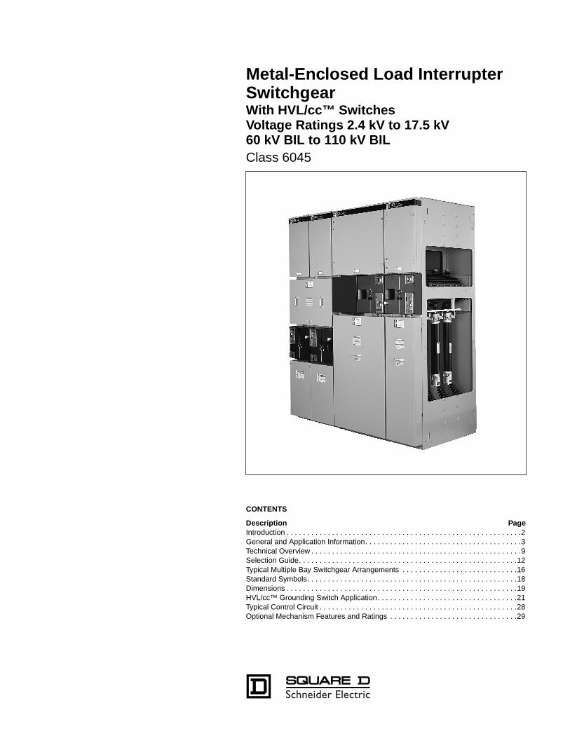
Metal-Enclosed Load Interrupter Switchgear
With HVL/cc™ Switches Voltage Ratings 2.4 kV to 17.5 kV60 kV BIL to 110 kV BIL
Class 6045
CONTENTS
Description Page
Introduction . . . . . . . . . . . . . . . . . . . . . . . . . . . . . . . . . . . . . . . . . . . . . . . . . . . . . . . . .2General and Application Information. . . . . . . . . . . . . . . . . . . . . . . . . . . . . . . . . . . . . .3Technical Overview . . . . . . . . . . . . . . . . . . . . . . . . . . . . . . . . . . . . . . . . . . . . . . . . . . .9Selection Guide. . . . . . . . . . . . . . . . . . . . . . . . . . . . . . . . . . . . . . . . . . . . . . . . . . . . .12Typical Multiple Bay Switchgear Arrangements . . . . . . . . . . . . . . . . . . . . . . . . . . . .16Standard Symbols. . . . . . . . . . . . . . . . . . . . . . . . . . . . . . . . . . . . . . . . . . . . . . . . . . .18Dimensions . . . . . . . . . . . . . . . . . . . . . . . . . . . . . . . . . . . . . . . . . . . . . . . . . . . . . . . .19HVL/cc™ Grounding Switch Application. . . . . . . . . . . . . . . . . . . . . . . . . . . . . . . . . .21Typical Control Circuit . . . . . . . . . . . . . . . . . . . . . . . . . . . . . . . . . . . . . . . . . . . . . . . .28Optional Mechanism Features and Ratings . . . . . . . . . . . . . . . . . . . . . . . . . . . . . . .29
Introduction
© 1999 Square D All Rights Reserved
2
5/99
Intr oduction
The HVL/cc™ Metal-Enclosed Load Interrupter Switchgear from Square D provides switching, metering, and interrupting capabilities for medium-voltage electrical power distribution systems.
It is designed to provide better performance and reliability, lower electrical costs, allow ease of system expansion and reduce equipment expense for systems ranging from 2.4 kV to 17.5 kV, 60 kV BIL—110 kV BIL. This switchgear is noted for its versatility, durability, and convenience. It has proven reliable both as service entrance equipment and in controlling substation transformers and is designed and manufactured in accordance with ANSI/IEEE, NEMA, CAN/CSA, UL and CUL standards C37.20.3, C37.20.4, C37.57, C37.58, CSA 22.2 no. 31, CSA 22.2 no. 193, and NEMA SG5 where applicable.
Made up of modular units, the HVL/cc is easy to expand. Two main bus positions allow future extensions and connections to existing equipment.
HVL/cc switchgear is available in either single or multiple bay units. To simplify handling and installation, each section is assembled before shipping. The design is compact, with front accessibility.
The HVL/cc switch can be equipped with either an over-toggle mechanism (OTM), which is standard, or an optional stored energy mechanism (SEM). An option with both mechanisms is the FUSELOGIC™ system. The FUSELOGIC system offers fuse tripping (with SEM) to provide protection against single phasing loads when a fuse has blown. It also has a mechanical interlock to prevent inadvertent switching until fuses have been installed or blown fuses have been replaced. (Additional details on page 5). An optional blown fuse flag is available with either OTM or SEM. The FUSELOGIC system on OTM offers 1 N.O.-1 N.C. auxiliary contact in addition to the blown fuse flag. The mechanical lockout feature is also included on OTM.
Mechanical interlocks are standard. This feature protects the operator by preventing the removal of the load-side panel while the load interrupter switch is closed and/or the optional ground switch is open.
HVL/cc switchgear is available for both indoor and outdoor enclosures. Each has features to ensure convenience, reliability, and durability.
Indoor switchgear includes lifting angles at the top corners of each shipping section for ease in handling, provisions for expansion, an 11 gauge steel enclosure, full-length ground bus in multiple bay enclosures, and padlocking for the load-side panel. Optional features include key interlocking and clear windows for inspection of optional load discharge assembly.
The outdoor switchgear is solidly constructed with a rear-sloping roof, a steel welded base and 11 gauge steel enclosure, gasketed front doors and strip heaters in each switch bay. Operating handles are enclosed by outer bulkhead type door.
The HVL/cc enclosure is designed for front access only and with minimum clearance can be positioned against walls, in small rooms or in prefabricated buildings. The small footprint can result in considerable cost savings from the reduction of building or room sizes.
Meter bays are available in both hot and cold sequence designs for Utilities and/or customer requirements (Consult factory for Dimensions and Availability).
Special utility metering bays can be provided as with our conventional HVL Metal-Enclosed switchgear.
General and Application Information
3
5/99 © 1999 Square D All Rights Reserved
General
Improved system performance and reliability, lower electrical power cost, easier system expansion, and reduced equipment expense are issues commanding serious attention in 2400 V to 17,500 V electrical power distribution system planning.
Square D Metal-Enclosed Load Interrupter Switchgear functions as a prime component of these systems providing necessary switching and overcurrent protection for the medium-voltage feeders. It is often used in conjunction with Square D unit substations. The switchgear is most frequently applied as service entrance equipment, although it performs equally well in controlling substation transformers and in sectionalizing medium-voltage feeder systems.
Standar d Features
• Tested per ANSI standards C37.20.3, C37.20.4, C37.57, C37.58, CSA 22.2 no. 31, CSA 22.2 no. 193, and NEMA SG5 where applicable.
• Over Toggle Mechanism Type OTM
• Fuse/cable access panel automatically interlocked with the load interrupter switch and the optional Grounding Switch.
• Removable operating handles
• With the optional Grounding Switch, the cable/fuse compartment is not accessible unless the grounding switch is closed into the grounded position.
• Visible isolation viewing ports to view open, closed and grounded positions.
• Standard live line indicators that are powered by capacitor dividers internal to the insulators
— On incoming circuits:Provide “Incoming Live Line” Indication.Provide “Incoming Line De-energized” Indication.
— On feeder circuits:Provide “Circuit Energized” Indication.Provide “Circuit De-energized” Indication.Provide “Blown Fuse” Indication.Provide “Back-fed Circuit” Indication.
• Animated Mimic Bus
— On ungrounded switches indicates “Closed” and “Open” Positions.
— Units with grounding switches indicate “Closed”, “Open” and “Grounded” Positions.
• Cable lugs. (1 set per phase)
— Up to 2- 500 kcmil cables per phase in switch cells
— Up to 3- 500 kcmil cables per phase in incoming line terminal chambers
• 600 Ampere tin plated copper main bus
• Belleville washers for all power connections
• Bi-Phenol epoxy switch enclosure and insulators
• UL/cUL Label.
• Suitable for Service Entrance Label.
• Meets NEC requirements for Service Entrance. (1999 Requirements)
• Tested to IEC 420 for switch-fuse combinations.
• 11 gauge steel enclosure.
•
1
⁄
4
by 2" copper ground bus meeting ANSI requirements for short circuit grounding.
• Duplex Switches. Single access panel automatically interlocked to prevent access unless both switches are opened (key interlocks are not required).
• Provision for padlocks and/or key locks.
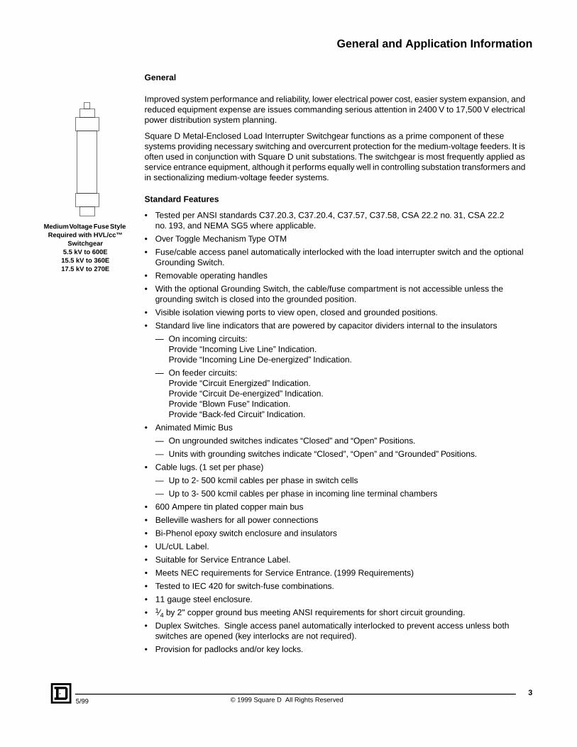
Medium Volta ge Fuse Style Required with HVL/cc™
Switc hgear5.5 kV to 600E
15.5 kV to 360E17.5 kV to 270E
General and Application Information
© 1999 Square D All Rights Reserved
4
5/99
Options and Accessories
• Square D “DIN STYLE” current limiting fuses (with ANSI E-rated curves). These fuses are manufactured by Bussmann and are stocked by Square D Company in Smyrna as well as by Bussmann in St Louis.
• The FUSELOGIC™ system for Blown/Missing Fuse Indication (Local or Remote) and mechanical lockout feature to prevent reclosing the switch until 3 new fuses have been installed.
— Anti-Single phasing protection due to blown fuses with the FUSELOGIC system
— Blown fuse indicating contact for remote indication (one common contact)
• Fault making Grounding Switch.
— On incoming switches grounds the incoming line
— On feeder switches grounds the outgoing load
• Load discharge assembly for fused units only (used to discharge capacitive voltage in cables under blown fuse conditions)
• Switch position auxiliary switch
• Main Bus 1200 Ampere tin plated copper
• Live Line indicators on main bus
• Infrared viewing windows for main bus and fuse/cable compartments.
• Dual spring stored energy mechanism type SEM
• Motor operator for OTM and SEM mechanisms
• Opening and closing coils (SEM Mechanism only).
• Fast / Auto transfer configuration (Main-Main and Main-Tie Main)
— Electrically interlocked.
— Mechanically interlocked.
— Operated from live line indicators.
— Protective relaying - ANSI 51, 46, 27, 59, 47
• Duplex Configuration
— Keyless interlock to lockout simultaneous closure of both duplex switches
• Surge Arresters (GE Type Tranquell
®
XE Polymer Only)
— Distribution, Intermediate and Station Class
≤
12 kV.Standard 14.75" (375 mm) switch section.Optional 20" (508 mm) and 29.50" (749 mm) section.
— Distribution, Intermediate and Station Class > 12 kV.Standard 20" (508 mm) switch section.Optional 29.50" (749 mm) section.
• Modified cubicle widths for customers wanting additional working space for cable termination and fuse removal:
— 20" (508 mm)
— 29.50" (749 mm)
• Low Voltage Compartment with hinged door.
— Space for PowerLogic Metering or relaying.
— Space for control components.
• Heaters with thermostat
• 12 Circuit Panelboard in CPT unit adjacent to the operating mechanism.
• Capacitor trip unit
• Transitions to other Square D Company medium voltage equipment and power transformers. (Consult Factory)
• Stainless steel enclosures for corrosive environments. (Consult Factory for Availability)
General and Application Information
5
5/99 © 1999 Square D All Rights Reserved
The FUSELOGIC
™
System
The new Square D medium voltage current limiting fuse sets the standard for features and protection. The new extended travel blown fuse indicator provides extended travel and increased energy to positively operate this optional feature.
The new FUSELOGIC system also prevents closing the HVL/cc™ switch if a fuse is blown or has not been installed. This reduces the potential of equipment damage due to single phasing because of a blown fuse. The FUSELOGIC system can be used to operate auxiliary contacts for optional local and/or remote indication or for fuse tripping.
NOTE: The FUSELOGIC system can only be operated by Square D fuses.
The fuse trip system requires the stored energy mechanism (SEM) with separate close and open springs. The motor operator is optional on both OTM and SEM.
For information about the FUSELOGIC system refer to Document number 6040DP9601 the FUSELOGIC system Application Guide or call Square D.
Type of Equipment A vailab le—Indoor and Outdoor Weatherpr oof
Single Bay Switc hgear
contains a single fused or unfused switch in a free-standing enclosure. It is ideally suited for locating close to a load to control a single medium-voltage circuit.
Special emphasis is placed on conduit area, cable entrance, and terminations. Normally, no main bus is furnished in a single bay. A ground pad bonded to the steel frame is furnished with a cable lug termination. This equipment is designed for front accessibility only and bottom cable entry is preferred.
Multiple Ba y Switc hgear
consists of a lineup of individual feeder switch bays connected to a common main bus. A main switch, fused or not fused, can be included in the lineup with a utility or user metering cubicle, depending upon job requirements. A continuous ground bus is bonded to the frame of each bay for the complete length of the lineup. The end cubicles are furnished with provisions for the addition of future feeder switch bays.
General and Application Information
© 1999 Square D All Rights Reserved
6
5/99
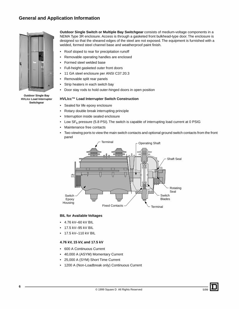
Outdoor
Single Switc h or Multiple Ba y Switc hgear
consists of medium-voltage components in a NEMA Type 3R enclosure. Access is through a gasketed front bulkhead-type door. The enclosure is designed so that the sheared edges of the steel are not exposed. The equipment is furnished with a welded, formed steel channel base and weatherproof paint finish.
• Roof sloped to rear for precipitation runoff
• Removable operating handles are enclosed
• Formed steel welded base
• Full-height gasketed outer front doors
• 11 GA steel enclosure per ANSI C37.20.3
• Removable split rear panels
• Strip heaters in each switch bay
• Door stay rods to hold outer-hinged doors in open position
HVL/cc™ Load Interrupter Switc h Construction
• Sealed for life epoxy enclosure
• Rotary double break interrupting principle
• Interruption inside sealed enclosure
• Low SF
6
pressure (5.8 PSI). The switch is capable of interrupting load current at 0 PSIG
• Maintenance free contacts
• Two viewing ports to view the main switch contacts and optional ground switch contacts from the front panel
BIL f or Availab le Volta ges
• 4.76 kV–60 kV BIL
• 17.5 kV–95 kV BIL
• 17.5 kV–110 kV BIL
4.76 kV, 15 kV, and 17.5 kV
• 600 A Continuous Current
• 40,000 A (ASYM) Momentary Current
• 25,000 A (SYM) Short Time Current
• 1200 A (Non-Loadbreak only) Continuous Current
Outdoor Single Ba y HVL/cc Load Interrupter
Switc hgear
Shaft Seal
Terminal
Terminal
SwitchEpoxy
Housing
SwitchBlades
RotatingSeal
Fixed Contacts
Operating Shaft
General and Application Information
7
5/99 © 1999 Square D All Rights Reserved
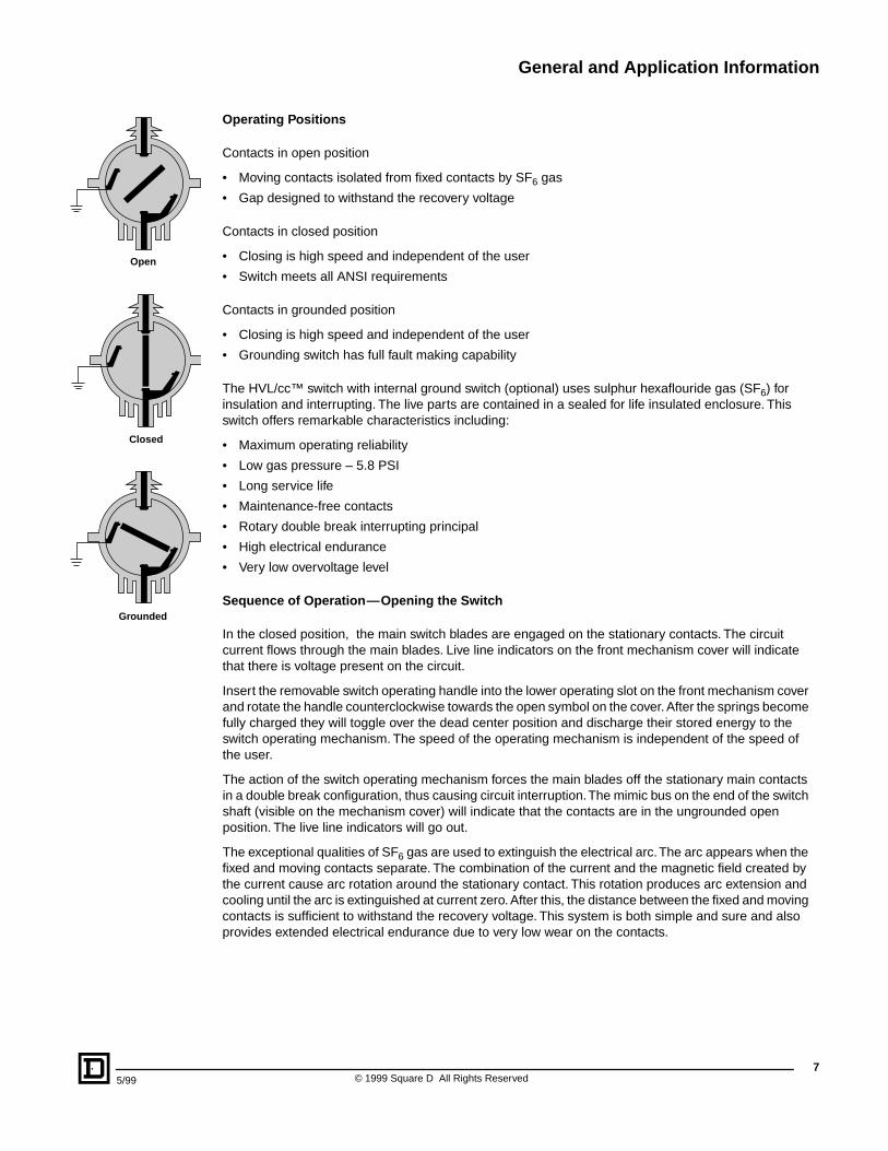
Operating Positions
Contacts in open position
• Moving contacts isolated from fixed contacts by SF
6
gas
• Gap designed to withstand the recovery voltage
Contacts in closed position
• Closing is high speed and independent of the user
• Switch meets all ANSI requirements
Contacts in grounded position
• Closing is high speed and independent of the user
• Grounding switch has full fault making capability
The HVL/cc™ switch with internal ground switch (optional) uses sulphur hexaflouride gas (SF
6
) for insulation and interrupting. The live parts are contained in a sealed for life insulated enclosure. This switch offers remarkable characteristics including:
• Maximum operating reliability
• Low gas pressure – 5.8 PSI
• Long service life
• Maintenance-free contacts
• Rotary double break interrupting principal
• High electrical endurance
• Very low overvoltage level
Sequence of Operation —Opening the Switc h
In the closed position, the main switch blades are engaged on the stationary contacts. The circuit current flows through the main blades. Live line indicators on the front mechanism cover will indicate that there is voltage present on the circuit.
Insert the removable switch operating handle into the lower operating slot on the front mechanism cover and rotate the handle counterclockwise towards the open symbol on the cover. After the springs become fully charged they will toggle over the dead center position and discharge their stored energy to the switch operating mechanism. The speed of the operating mechanism is independent of the speed of the user.
The action of the switch operating mechanism forces the main blades off the stationary main contacts in a double break configuration, thus causing circuit interruption. The mimic bus on the end of the switch shaft (visible on the mechanism cover) will indicate that the contacts are in the ungrounded open position. The live line indicators will go out.
The exceptional qualities of SF
6
gas are used to extinguish the electrical arc. The arc appears when the fixed and moving contacts separate. The combination of the current and the magnetic field created by the current cause arc rotation around the stationary contact. This rotation produces arc extension and cooling until the arc is extinguished at current zero. After this, the distance between the fixed and moving contacts is sufficient to withstand the recovery voltage. This system is both simple and sure and also provides extended electrical endurance due to very low wear on the contacts.
Open
Closed
Grounded
General and Application Information
© 1999 Square D All Rights Reserved
8
5/99
Sequence of Operation —Grounding the Switc h Main Contacts with Optional Gr ound Switc h
After the switch is in the ungrounded open position, the operating handle can be removed from the lower operating slot and inserted into the top grounding slot. These slots are mechanically interlocked to prevent incorrect operation sequence. Rotate the handle counterclockwise until the springs become fully charged and toggle over the dead center postion. The mechanism forces the main blades into the grounded postion. The speed of the operating mechanism is also independent from the speed of the user, indentical to the spring opening sequence. The mimic bus on the end of the switch shaft (visible on mechanism cover) will indicate that the contacts are in the grounded position. The front lower access panel can only be removed when the switch is in the grounded position.
Sequence of Operation —Closing the Switc h with Optional Gr ound Switc h
The front lower access panel must be installed and the switch blades removed from the grounded position (if supplied) before the switch main blades can be closed. Replace lower front access panel and insert the operating handle into the top grounding slot. Rotate the handle clockwise until the springs become fully charged and toggle over the dead center position. The mechanism forces the main blades into the ungrounded open position. The speed of the operating mechanism is also independent of the speed of the user. The mimic bus on the end of the switch shaft (visible on the mechanism cover) will indicate that the contacts are in the ungrounded open position. Because the ground switch is immersed in SF
6
gas, it has a short circuit making capability should a fault be on the circuit when the switch is operated.
After the switch is in the ungrounded open position, the handle may be removed from the top grounding slot and inserted into the lower operating slot. These slots are mechanically interlocked to lockout incorrect operation sequence. Rotate the handle clockwise until the springs become fully charged and they toggle over the dead center position. The mechanism forces the main blades into the closed position. The speed of the operating mechanism is also independent from the speed of the user. The mimic bus on the end of the switch shaft will indicate that the contacts are in the closed position. The live line indicators will indicate that voltage is present on the circuit.
When the movable main blades approach the stationary main blades, a high voltage arc is established across the diminishing SF
6
gap attempting to complete the circuit. The arc occurs between the tip of the stationary main contacts and the edge of the movable main blades. The arc is short and brief, since the fast closing blades minimize the arcing time. Spring pressure and the momentum of the fast moving main blades completely close the contacts. The force is great enough to cause the contacts to close even against the repelling short circuit magnetic forces if a fault exists on the circuit.
The switch nameplate prominently lists performance ratings, fuse supplied and equipment identification.
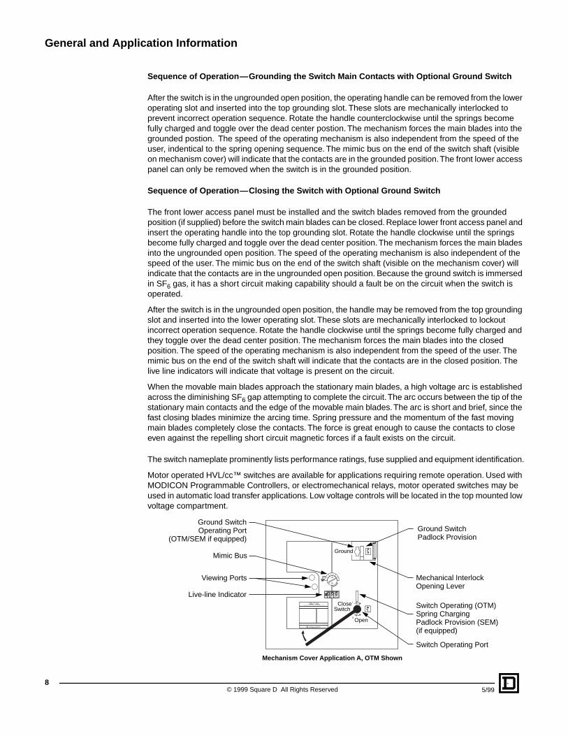
Motor operated HVL/cc™ switches are available for applications requiring remote operation. Used with MODICON Programmable Controllers, or electromechanical relays, motor operated switches may be used in automatic load transfer applications. Low voltage controls will be located in the top mounted low voltage compartment.
HVL ccLOAD CURRENT INTERRUPTER SWITCHGEAR
TM
SMYRNA, TN USA
0
OPEN
CLOSED
GRD
Ground
CloseSwitch
Open
Viewing Ports
Mimic Bus
Ground SwitchOperating Port
(OTM/SEM if equipped)Ground SwitchPadlock Provision
Switch Operating Port
Mechanical InterlockOpening Lever
Live-line Indicator
Switch Operating (OTM)Spring ChargingPadlock Provision (SEM)(if equipped)
Mechanism Cover Application A, OTM Shown
Technical Overview
9
5/99 © 1999 Square D All Rights Reserved
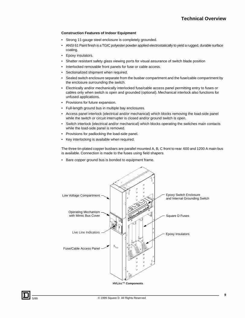
Construc tion Features of Indoor Equipment
• Strong 11-gauge steel enclosure is completely grounded.
• ANSI 61 Paint finish is a TGIC polyester powder applied electrostatically to yield a rugged, durable surface coating.
• Epoxy insulators.
• Shatter resistant safety glass viewing ports for visual assurance of switch blade position
• Interlocked removable front panels for fuse or cable access.
• Sectionalized shipment when required.
• Sealed switch enclosure separate from the busbar compartment and the fuse/cable compartment by the enclosure surrounding the switch.
• Electrically and/or mechanically interlocked fuse/cable access panel permitting entry to fuses or cables only when switch is open and grounded (optional). Mechanical interlock also functions for unfused applications.
• Provisions for future expansion.
• Full-length ground bus in multiple bay enclosures.
• Access panel interlock (electrical and/or mechanical) which blocks removing the load-side panel while the switch or circuit interrupter is closed and/or ground switch is open.
• Switch interlock (electrical and/or mechanical) which blocks operating the switches main contacts while the load-side panel is removed.
• Provisions for padlocking the load-side panel.
• Key interlocking is available when required.
The three tin-plated copper busbars are parallel mounted A, B, C front to rear. 600 and 1200 A main bus is available. Connection is made to the fuses using field shapers.
• Bare copper ground bus is bonded to equipment frame.
Low Voltage Compartment
Operating Mechanismwith Mimic Bus Cover
Fuse/Cable Access Panel
Square D Fuses
Epoxy Switch Enclosureand Internal Grounding Switch
Epoxy InsulatorsLive Line Indicators
HVL/cc™ Components
Technical Overview
© 1999 Square D All Rights Reserved
10
5/99
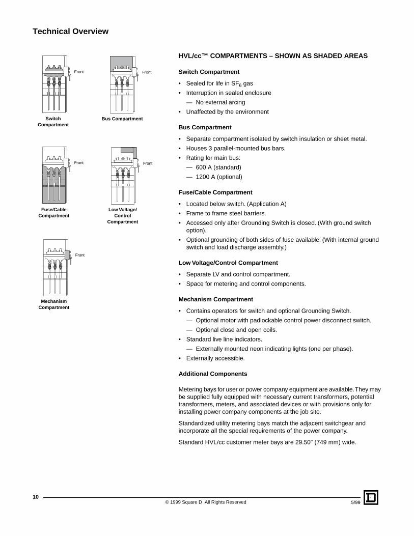
HVL/cc™ COMPARTMENTS – SHOWN AS SHADED AREAS
Switc h Compar tment
• Sealed for life in SF
6
gas
• Interruption in sealed enclosure
— No external arcing
• Unaffected by the environment
Bus Compar tment
• Separate compartment isolated by switch insulation or sheet metal.
• Houses 3 parallel-mounted bus bars.
• Rating for main bus:
— 600 A (standard)
— 1200 A (optional)
Fuse/Cab le Compar tment
• Located below switch. (Application A)
• Frame to frame steel barriers.
• Accessed only after Grounding Switch is closed. (With ground switch option).
• Optional grounding of both sides of fuse available. (With internal ground switch and load discharge assembly.)
Low Volta ge/Contr ol Compar tment
• Separate LV and control compartment.
• Space for metering and control components.
Mechanism Compar tment
• Contains operators for switch and optional Grounding Switch.
— Optional motor with padlockable control power disconnect switch.
— Optional close and open coils.
• Standard live line indicators.
— Externally mounted neon indicating lights (one per phase).
• Externally accessible.
Additional Components
Metering bays for user or power company equipment are available. They may be supplied fully equipped with necessary current transformers, potential transformers, meters, and associated devices or with provisions only for installing power company components at the job site.
Standardized utility metering bays match the adjacent switchgear and incorporate all the special requirements of the power company.
Standard HVL/cc customer meter bays are 29.50" (749 mm) wide.
Front Front
Front Front
Front
Switc hCompar tment
Bus Compar tment
Fuse/Cab le Compar tment
Low Volta ge/ Contr ol
Compar tment
Mechanism Compar tment
Technical Overview
11
5/99 © 1999 Square D All Rights Reserved
Cable Terminations
The load cables are connected directly to the terminals of the switch. Transformer cables are connected to the lower fuse holder/field shaper.
Cables may have either:
• simplified terminations for dry-type one or three-core cables
• heat-shrink ends for dry-type or paper-insulated cables.
With basic equipment, the maxium cable sizes are:
• 3–500 kcmil for 1200 A incoming or outgoing terminal chambers.
• 2–500 kcmil for 600 A incoming or outgoing switch cubicles.
• 2–1/0 AWG for switches incorporating fuses and direct coupled to transformers.
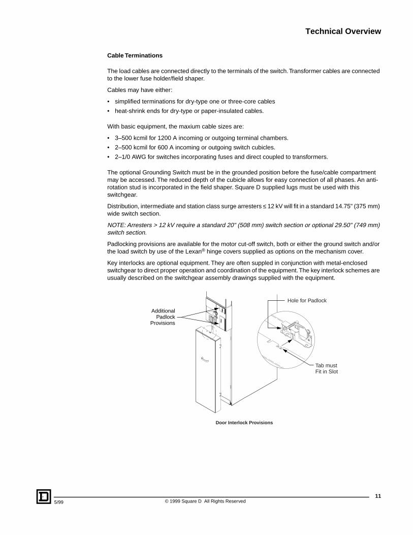
The optional Grounding Switch must be in the grounded position before the fuse/cable compartment may be accessed. The reduced depth of the cubicle allows for easy connection of all phases. An anti-rotation stud is incorporated in the field shaper. Square D supplied lugs must be used with this switchgear.
Distribution, intermediate and station class surge arresters
≤
12 kV will fit in a standard 14.75" (375 mm) wide switch section.
NOTE: Arresters > 12 kV require a standard 20" (508 mm) switch section or optional 29.50" (749 mm) switch section.
Padlocking provisions are available for the motor cut-off switch, both or either the ground switch and/or the load switch by use of the Lexan
®
hinge covers supplied as options on the mechanism cover.
Key interlocks are optional equipment. They are often suppled in conjunction with metal-enclosed switchgear to direct proper operation and coordination of the equipment. The key interlock schemes are usually described on the switchgear assembly drawings supplied with the equipment.
AdditionalPadlock
Provisions
Tab mustFit in Slot
Hole for Padlock
Door Interlock Provisions
Selection Guide
© 1999 Square D All Rights Reserved
12
5/99
Integrated Equipment Ratings
Medium-voltage metal-enclosed load interrupter switchgear is an integrated assembly of many components, properly selected and coordinated to provide reliable operation of the over-all equipment. Each component has its own ratings defined by its own industry standards (usually ANSI). In the past, these individual component ratings have been emphasized, since they often appear to be quite impressive but may be irrelevant to the component’s application. The result has been confusion and a shifting of the burden for analysis, selection and coordination of specific components from the equipment manufacturer to the purchaser, who would rather evaluate over-all equipment performance.
Integrated ratings of the complete equipment are the natural solution, and Square D switchgear is rated in this manner. Integral equipment ratings are readily comparable with the anticipated voltage, short circuit and continuous current values obtained when designing a distribution system.
Table A below covers the HVL/cc™ load interrupter switches when applied without fuses.
Integrated Short-Circuit Current Ratings with Square D current limiting fuses are shown in Table B on page 14. Integrated equipment short-circuit current rating at a given voltage defines the maximum short circuit current to which the entire equipment may be subjected without damage to the equipment or endangering the operating personnel.
Current ANSI standards for metal-enclosed switchgear and the components are rated individually in rms symmetrical amperes. The integrated rating may also be expressed this way (the asymmetrical rating is obtained by multiplying the symmetrical value by 1.6). For convenience when comparing to older equipment, the integrated rating is also expressed in “MVA”. The MVA ratings are calculated at the nominal system voltage and with the rms symmetrical amperes, e.g.: MVA = Nominal System Voltage, kV x Amperes rms sym kA x
√
3.
The integrated equipment rating combines the following ratings:
1. Switchgear–momentary and short time (bus bracing)
2. Load Interrupter Switch–momentary, fault closing and short time.
3. Fuses–interrupting and energy let-through characteristics (current limiting fuses limit the energy during a short circuit thereby allowing higher integrated ratings than the switches and switchgear would have if unfused).
4. Other components that may have limited capabilities.
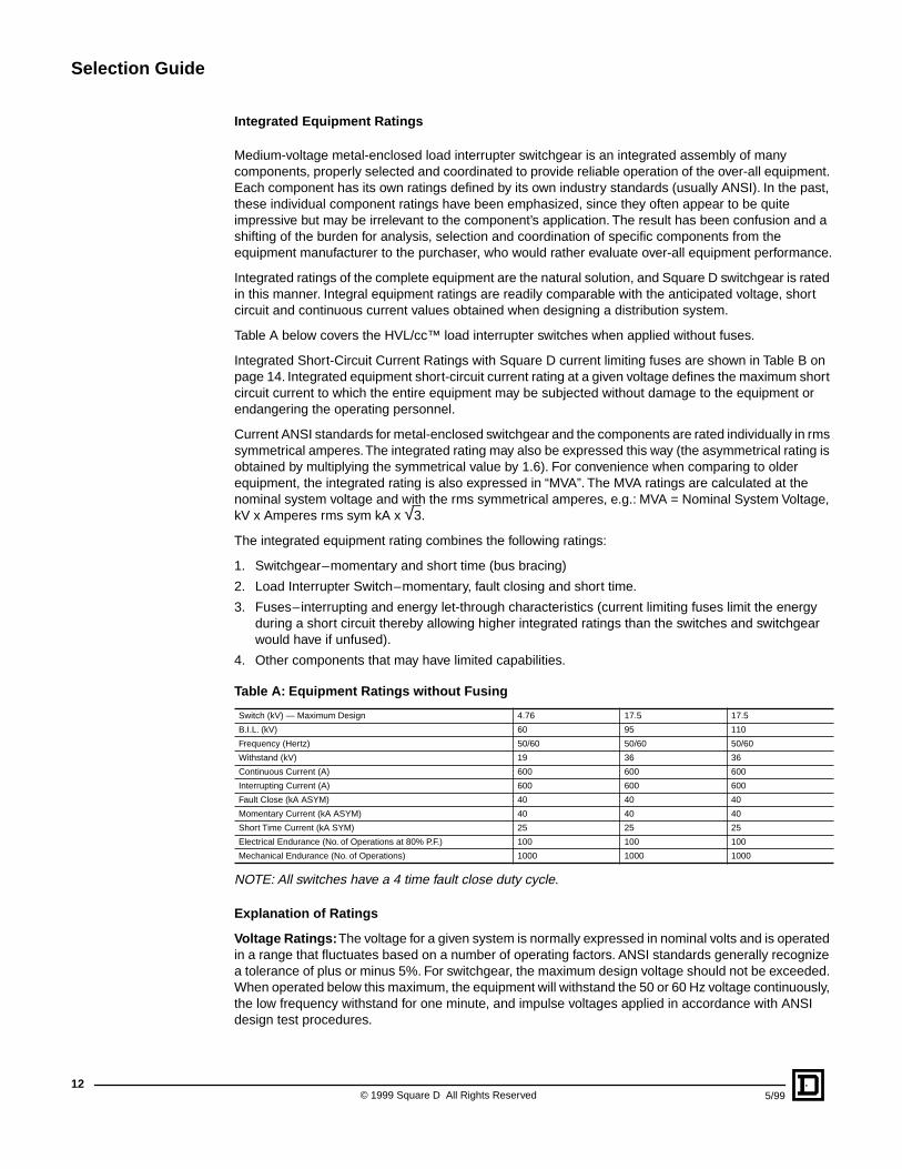
NOTE: All switches have a 4 time fault close duty cycle.
Explanation of Ratings
Volta ge Ratings:
The voltage for a given system is normally expressed in nominal volts and is operated in a range that fluctuates based on a number of operating factors. ANSI standards generally recognize a tolerance of plus or minus 5%. For switchgear, the maximum design voltage should not be exceeded. When operated below this maximum, the equipment will withstand the 50 or 60 Hz voltage continuously, the low frequency withstand for one minute, and impulse voltages applied in accordance with ANSI design test procedures.
Table A: Equipment Ratings without Fusing
Switch (kV) — Maximum Design 4.76 17.5 17.5
B.I.L. (kV) 60 95 110
Frequency (Hertz) 50/60 50/60 50/60
Withstand (kV) 19 36 36
Continuous Current (A) 600 600 600
Interrupting Current (A) 600 600 600
Fault Close (kA ASYM) 40 40 40
Momentary Current (kA ASYM) 40 40 40
Short Time Current (kA SYM) 25 25 25
Electrical Endurance (No. of Operations at 80% P.F.) 100 100 100
Mechanical Endurance (No. of Operations) 1000 1000 1000
Selection Guide
13
5/99 © 1999 Square D All Rights Reserved
Contin uous Current Rating:
The over-all continuous current is determined by the component with the smallest capacity–bussing, load interrupter switch, fuses, fuse mountings, connections, etc. Unfused equipment is normally rated by the main bus which is available in ratings of 600 or 1200 Amperes continuous. The continuous current rating of fused equipment is generally determined by the fuses since the other components have greater current carrrying capacities than the fuses.
HVL/cc™ Switc h Interrupting Current Rating:
The HVL/cc switch is designed and tested in accordance with ANSI standards as a “load interrupter” switch, capable of interrupting load currents up to its continuous current rating. However, per ANSI, this switch is not intended to be the main switching device. Load interrupter switches are not designed or tested for interrupting currents above their continuous currents.
Full Load Current Switc hing Endurance:
In accordance with ANSI C37.20.4, the number of full load current interruptions at maximum design voltage which the switch can make is established through tests on “a circuit having a 0.8 power factor lagging,” and “requiring no maintenance for the number of operations stated.”
Shor t-Cir cuit Current Ratings:
An integrated short-circuit current rating is normally established based on the Momentary, 2-second short time, and fault close capabilities of the equipment as explained in the section above on “Integrated Equipment Ratings”. The most important number is the Integrated Short-Circuit Current Rating which establishes overall rating for the equipment. This number is normally based on unfused switches. Current-limiting fuses can be used to increase the integrated rating. Use Table B on page 14 to select the proper fuse and associated integrated short-circuit current rating.
Mechanical Endurance:
These numbers represent actual test values that the given switch rating has been subjected to. ANSI Standard C37.20.3 and proposed standard C37.20.4 do not require a “rating,” only testing to a specified minimum number of operations without repair, component replacement, or maintenance. In all cases the switch rating shown has been tested to many more than the minimum number of operations shown here.
Medium Volta ge Fuse Selection
Fuses are usually used with the medium-voltage switch to provide overcurrent protection. They are normally mounted vertically below the switch (Application A). When an Application B (inverted) arrangement is used, the fuses are mounted above the switch.
Unless user job requirements demand otherwise, fuses are always connected to the load-side of the switch and are de-energized when the switch is open. When mounted in the switchgear, the fuses are readily accessible through an interlocked panel for easy removal.
Square D current limiting fuses must be provided in Square D HVL/cc™ Metal-Enclosed Switchgear. These provide short-circuit current interrupting protection equal to or greater than the short-circuit current rating of the equipment in accordance with their nominal current ratings and characteristic curves.
Current limiting type fuses offer the maximum short-circuit current rating and are most economical in the majority of “E” ratings in which they are available.
Fuses supplied with the equipment provide the following conditions when properly selected:
1. Fuse interrupting capacity will be in accordance with the integrated equipment short-circuit current rating.
2. Fuse continuous current “E” rating will be as required up to the maximum continuous current rating of the fuse.
3. Most applications seem to favor fast acting current limiting fuses. These fuses limit the let-through current and minimize the short circuit damage to a system. The fuses, completely factory assembled and sealed, keep out dust or foreign material, and operate without any noise, pressure or expulsion of gas, flame and extinguishing material, even at maximum capacity. Boric acid fuses are not available with HVL/cc switchgear.
Selection Guide
© 1999 Square D All Rights Reserved
14
5/99
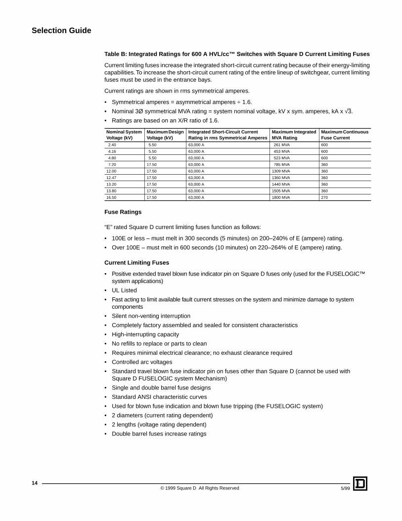
Table B: Integrated Ratings f or 600 A HVL/cc™ Switc hes with Square D Current Limiting Fuses
Current limiting fuses increase the integrated short-circuit current rating because of their energy-limiting capabilities. To increase the short-circuit current rating of the entire lineup of switchgear, current limiting fuses must be used in the entrance bays.
Current ratings are shown in rms symmetrical amperes.
• Symmetrical amperes = asymmetrical amperes ÷ 1.6.
• Nominal 3Ø symmetrical MVA rating = system nominal voltage, kV x sym. amperes, kA x
√
3.
• Ratings are based on an X/R ratio of 1.6.
Fuse Ratings
“E” rated Square D current limiting fuses function as follows:
• 100E or less – must melt in 300 seconds (5 minutes) on 200–240% of E (ampere) rating.
• Over 100E – must melt in 600 seconds (10 minutes) on 220–264% of E (ampere) rating.
Current Limiting Fuses
• Positive extended travel blown fuse indicator pin on Square D fuses only (used for the FUSELOGIC™ system applications)
• UL Listed
• Fast acting to limit available fault current stresses on the system and minimize damage to system components
• Silent non-venting interruption
• Completely factory assembled and sealed for consistent characteristics
• High-interrupting capacity
• No refills to replace or parts to clean
• Requires minimal electrical clearance; no exhaust clearance required
• Controlled arc voltages
• Standard travel blown fuse indicator pin on fuses other than Square D (cannot be used with Square D FUSELOGIC system Mechanism)
• Single and double barrel fuse designs
• Standard ANSI characteristic curves
• Used for blown fuse indication and blown fuse tripping (the FUSELOGIC system)
• 2 diameters (current rating dependent)
• 2 lengths (voltage rating dependent)
• Double barrel fuses increase ratings
Nominal System Volta ge (kV)
Maxim um Design Volta ge (kV)
Integrated Shor t-Cir cuit Current Rating in rms Symmetrical Amperes
Maxim um Integrated MVA Rating
Maxim um Contin uous Fuse Current
2.40 5.50 63,000 A 261 MVA 600
4.16 5.50 63,000 A 453 MVA 600
4.80 5.50 63,000 A 523 MVA 600
7.20 17.50 63,000 A 785 MVA 360
12.00 17.50 63,000 A 1309 MVA 360
12.47 17.50 63,000 A 1360 MVA 360
13.20 17.50 63,000 A 1440 MVA 360
13.80 17.50 63,000 A 1505 MVA 360
16.50 17.50 63,000 A 1800 MVA 270
Selection Guide
15
5/99 © 1999 Square D All Rights Reserved
Ratings and Selection
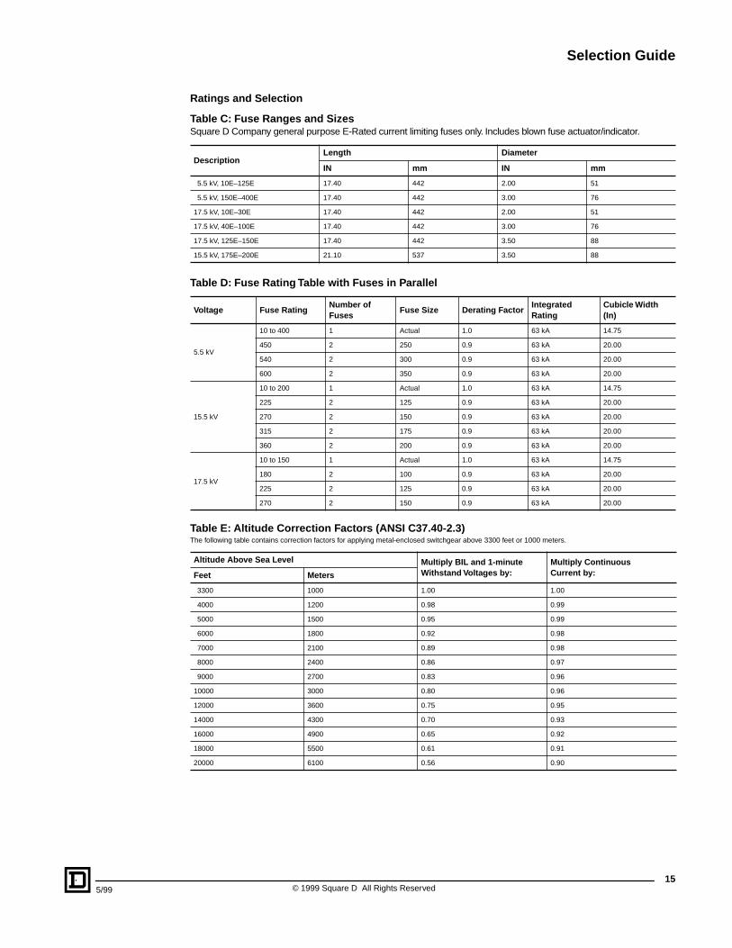
Table C: Fuse Rang es and Siz es
Square D Company general purpose E-Rated current limiting fuses only. Includes blown fuse actuator/indicator.
Table D: Fuse Rating Table with Fuses in P arallel
DescriptionLength Diameter
IN mm IN mm
5.5 kV, 10E–125E 17.40 442 2.00 51
5.5 kV, 150E–400E 17.40 442 3.00 76
17.5 kV, 10E–30E 17.40 442 2.00 51
17.5 kV, 40E–100E 17.40 442 3.00 76
17.5 kV, 125E–150E 17.40 442 3.50 88
15.5 kV, 175E–200E 21.10 537 3.50 88
Volta ge Fuse RatingNumber of Fuses
Fuse Siz e Derating F actorIntegrated Rating
Cubic le Width (In)
5.5 kV
10 to 400 1 Actual 1.0 63 kA 14.75
450 2 250 0.9 63 kA 20.00
540 2 300 0.9 63 kA 20.00
600 2 350 0.9 63 kA 20.00
15.5 kV
10 to 200 1 Actual 1.0 63 kA 14.75
225 2 125 0.9 63 kA 20.00
270 2 150 0.9 63 kA 20.00
315 2 175 0.9 63 kA 20.00
360 2 200 0.9 63 kA 20.00
17.5 kV
10 to 150 1 Actual 1.0 63 kA 14.75
180 2 100 0.9 63 kA 20.00
225 2 125 0.9 63 kA 20.00
270 2 150 0.9 63 kA 20.00
Table E: Altitude Correction F actor s (ANSI C37.40-2.3)
The following table contains correction factors for applying metal-enclosed switchgear above 3300 feet or 1000 meters.
Altitude Abo ve Sea Level Multipl y BIL and 1-min ute Withstand Volta ges by:
Multipl y Contin uous Current b y:Feet Meters
3300 1000 1.00 1.00
4000 1200 0.98 0.99
5000 1500 0.95 0.99
6000 1800 0.92 0.98
7000 2100 0.89 0.98
8000 2400 0.86 0.97
9000 2700 0.83 0.96
10000 3000 0.80 0.96
12000 3600 0.75 0.95
14000 4300 0.70 0.93
16000 4900 0.65 0.92
18000 5500 0.61 0.91
20000 6100 0.56 0.90
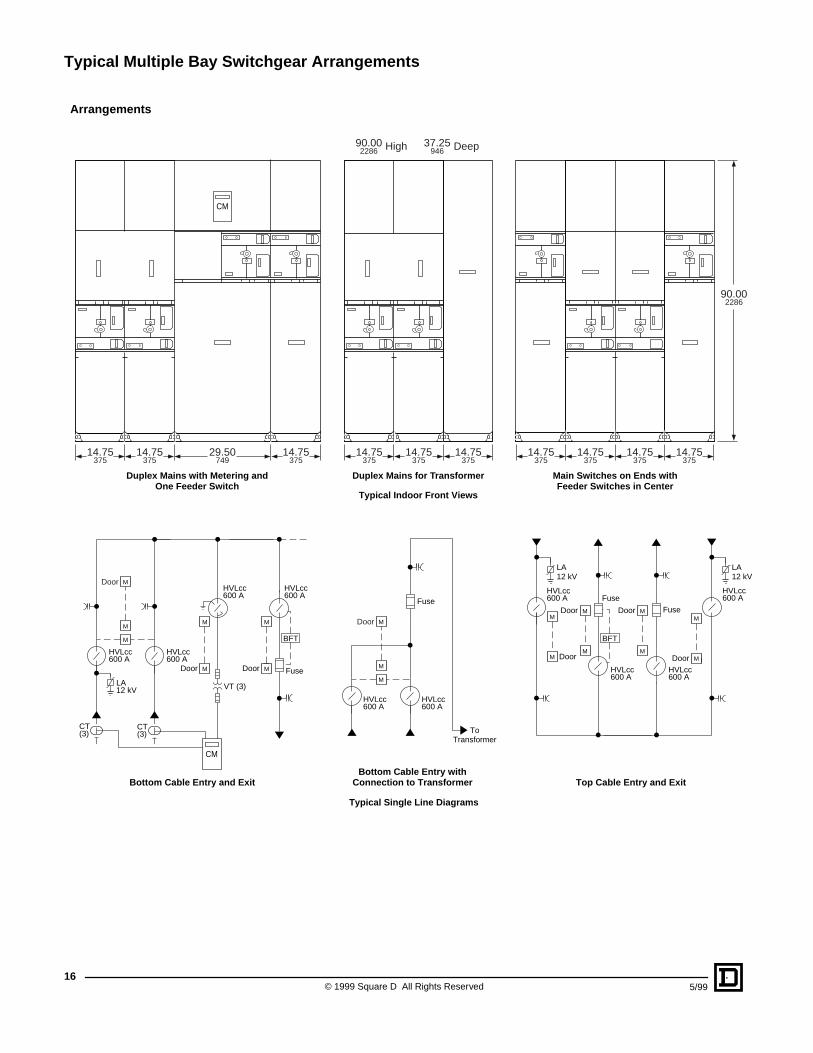
Typical Multiple Bay Switchgear Arrangements
© 1999 Square D All Rights Reserved
16
5/99
Arrang ements
Typical Indoor Front Views
14.75375
90.002286 High 37.25
946 Deep
14.75375
14.75375
14.75375
14.75375
14.75375
14.75375
14.75375
90.002286
14.75375
29.50749
14.75375
CM
Duplex Mains with Metering andOne Feeder Switch
Duplex Mains for Transformer Main Switches on Ends withFeeder Switches in Center
Door M
M
M
M
M
HVLcc600 A
HVLcc600 A
HVLcc600 A
HVLcc600 A
HVLcc600 A
HVLcc600 A
HVLcc600 A
HVLcc600 A
HVLcc600 A
HVLcc600 A
CT(3)
CT(3)
LA12 kV
Door M
M
Door
M
M
M
MDoor
M
MDoor
M
M
DoorDoor
Fuse
FuseFuse
Fuse
VT (3)
LA12 kV
LA12 kV
Door M
M
M
BFT BFT
ToTransformer
Typical Single Line Diagrams
Top Cable Entry and ExitBottom Cable Entry and ExitBottom Cable Entry with
Connection to Transformer
CM
Typical Multiple Bay Switchgear Arrangements
17
5/99 © 1999 Square D All Rights Reserved
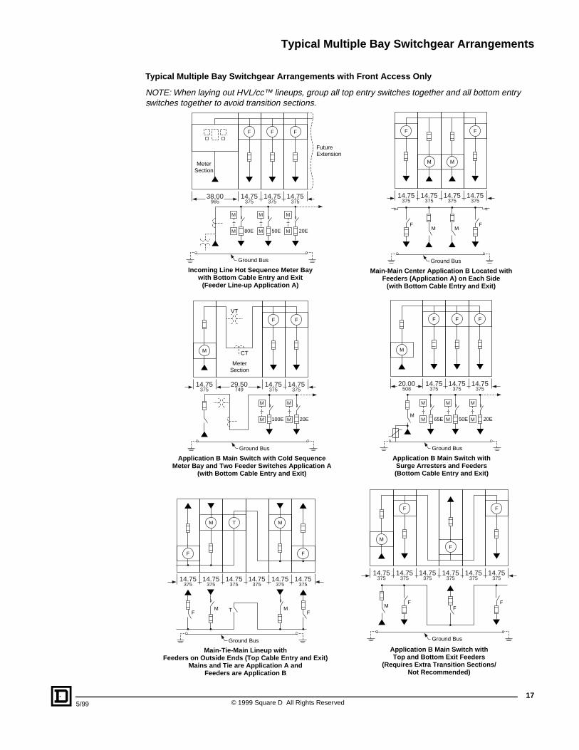
Typical Multiple Ba y Switc hgear Arrang ements with Fr ont Access Onl y
NOTE: When laying out HVL/cc™ lineups, group all top entry switches together and all bottom entry switches together to avoid transition sections.
14.75375
M
M
Incoming Line Hot Sequence Meter Baywith Bottom Cable Entry and Exit
(Feeder Line-up Application A)
20E
M
M 50E
M
M 80E
Ground Bus
F
38.00965
FutureExtension
MeterSection
14.75375
F
14.75375
F
14.75375
M
M
Application B Main Switch with Cold SequenceMeter Bay and Two Feeder Switches Application A
(with Bottom Cable Entry and Exit)
20E
M
M 100E
Ground Bus
F
29.50749
14.75375
F
14.75375
M
VT
CT
MeterSection
14.75375
Main-Main Center Application B Located withFeeders (Application A) on Each Side
(with Bottom Cable Entry and Exit)
FMM
Ground Bus
F
F
F
14.75375
14.75375
14.75375
M M
14.75375
M
M
Application B Main Switch withSurge Arresters and Feeders(Bottom Cable Entry and Exit)
20E
M
M 50E
M
M 65E
Ground Bus
F
20.00508
14.75375
F
14.75375
F
M
M
14.75375
Main-Tie-Main Lineup withFeeders on Outside Ends (Top Cable Entry and Exit)
Mains and Tie are Application A andFeeders are Application B
FMM T
FF
F
14.75375
14.75375
14.75375
14.75375
M T
14.75375
M
Ground Bus
14.75375
14.75375
14.75375
F
F
14.75375
14.75375
F
14.75375
M
Application B Main Switch withTop and Bottom Exit Feeders
(Requires Extra Transition Sections/Not Recommended)
M
Ground Bus
FF
F
Standard Symbols
© 1999 Square D All Rights Reserved
18
5/99
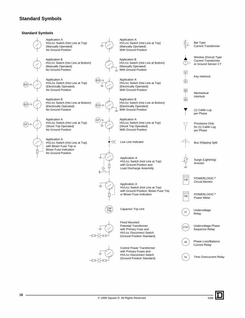
Standard Symbols
EO
EO
CM POWERLOGIC ®
Circuit Monitor
POWERLOGIC ®
Power MeterPM
Undervoltage Phase Sequence Relay
Phase Loss/BalanceCurrent Relay
UndervoltageRelay
Time Overcurrent Relay
27/47
46
27
51
MechanicalInterlock
Key Interlock
M
M
K
K
(1) Cable Lug per Phase
Provisions Onlyfor (1) Cable Lugper Phase
Fixed MountedPotential Transformerwith Primary Fuse andHVL/cc Disconnect Switch(Ground Position Standard)
Control Power Transformerwith Primary Fuses andHVL/cc Disconnect Switch(Ground Position Standard)
Window (Donut) TypeCurrent Transformeror Ground Sensor CT
Bar TypeCurrent Transformer
Capacitor Trip UnitCapTrip
ST
Application AHVL/cc Switch (Hot Line at Top)with Ground Position andLoad Discharge Assembly
Live Line Indicator
Application AHVL/cc Switch (Hot Line at Top)with Ground Position, Blown Fuse Tripor Blown Fuse Indication
EO
EO
Application AHVL/cc Switch (Hot Line at Top)(Manually Operated)No Ground Position
Application BHVL/cc Switch (Hot Line at Bottom)(Manually Operated)No Ground Position
Application AHVL/cc Switch (Hot Line at Top)(Electrically Operated)No Ground Position
Application BHVL/cc Switch (Hot Line at Bottom)(Electrically Operated)No Ground Position
ST
Application AHVL/cc Switch (Hot Line at Top)(Shunt Trip Operated)No Ground Position
Application AHVL/cc Switch (Hot Line at Top)(Manually Operated)With Ground Position
Application BHVL/cc Switch (Hot Line at Bottom)(Manually Operated)With Ground Position
Application AHVL/cc Switch (Hot Line at Top)(Electrically Operated)With Ground Position
Application BHVL/cc Switch (Hot Line at Bottom)(Electrically Operated)With Ground Position
Application AHVL/cc Switch (Hot Line at Top)(Shunt Trip Operated)With Ground Position
Application AHVL/cc Switch (Hot Line at Top)with Blown Fuse Trip orBlown Fuse IndicationNo Ground Position
Bus Shipping Split
Surge (Lightning)Arrester
Dimensions
19
5/99 © 1999 Square D All Rights Reserved
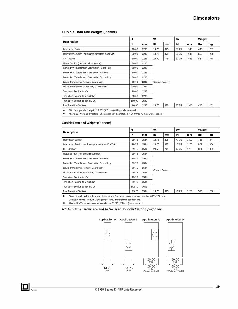
Cubic le Data and Weight (Indoor)
Cubic le Data and Weight (Outdoor)
NOTE: Dimensions are
not
to be used for construction purposes.
DescriptionH W D
q
Weight
IN mm IN mm IN mm lbs kg
Interrupter Section 90.00 2286 14.75 375 37.25 946 445 202
Interrupter Section (with surge arresters
≤
12 kV)
t
90.00 2286 14.75 375 37.25 946 503 228
CPT Section 90.00 2286 29.50 749 37.25 946 834 378
Meter Section (hot or cold sequence) 90.00 2286
Consult Factory
Power Dry Transformer Connection (Model 36) 90.00 2286
Power Dry Transformer Connection Primary 90.00 2286
Power Dry Transformer Connection Secondary 90.00 2286
Liquid Transformer Primary Connection 90.00 2286
Liquid Transformer Secondary Connection 90.00 2286
Transition Section to HVL 90.00 2286
Transition Section to MetalClad 90.00 2286
Transition Section to 8198 MCC 100.00 2540
Bus Transition Section 90.00 2286 14.75 375 37.25 946 445 202
q
With front panels [footprint 33.25" (845 mm) with panels removed]
t
Above 12 kV surge arresters (all classes) can be installed in 20.00" (508 mm) wide section.
DescriptionH W D
k
Weight
IN mm IN mm IN mm lbs kg
Interrupter Section 99.75 2534 14.75 375 47.25 1200 765 347
Interrupter Section (with surge arresters
≤
12 kV)
t
99.75 2534 14.75 375 47.25 1200 807 366
CPT Section 99.75 2534 29.50 749 47.25 1200 864 392
Meter Section (hot or cold sequence) 99.75 2534
Consult Factory
Power Dry Transformer Connection Primary 99.75 2534
Power Dry Transformer Connection Secondary 99.75 2534
Liquid Transformer Primary Connection 99.75 2534
Liquid Transformer Secondary Connection 99.75 2534
Transition Section to HVL 99.75 2534
Transition Section to MetalClad 99.75 2534
Transition Section to 8198 MCC 102.40 2601
Bus Transition Section 99.75 2534 14.75 375 47.25 1200 525 238
k
Dimensions listed are floor plan dimensions. Roof overhangs front and rear by 5.00" (127 mm).
q
Contact Smyrna Product Management for all transformer connections.
t
Above 12 kV arresters can be installed in 20.00" (508 mm) wide section.
20.00508or
29.50749
(Wider on Left)
20.00508or
29.5074
(Wider on Right)
Application A
14.75375
Application A
14.75375
Application B Application B
Dimensions
© 1999 Square D All Rights Reserved
20
5/99
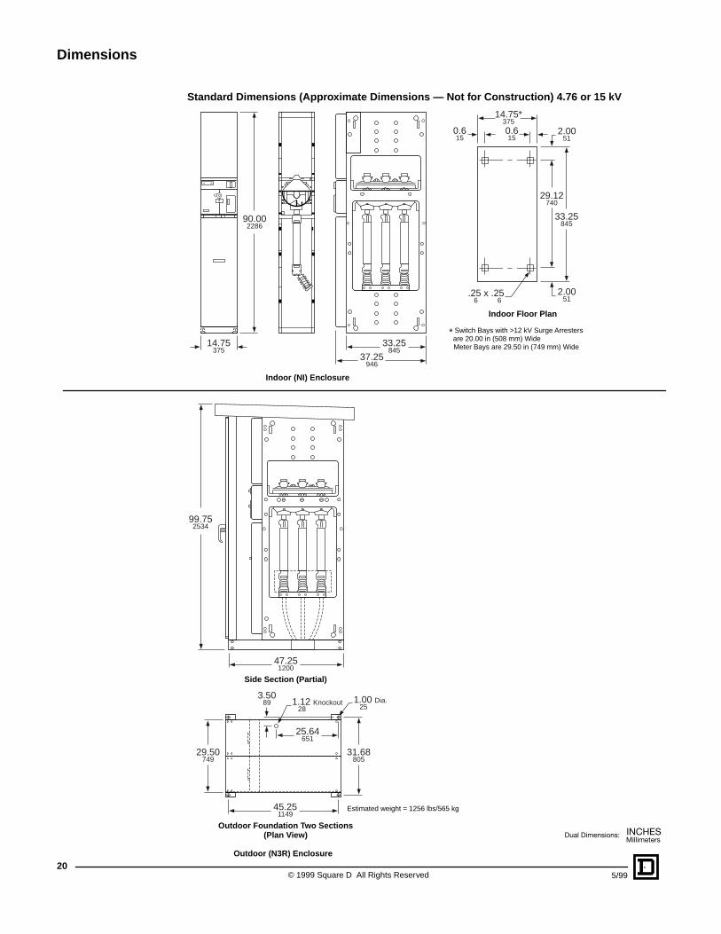
Standar d Dimensions (Appr oximate Dimensions — Not f or Construction) 4.76 or 15 kV
14.75375
.25 x .25 6 6
90.002286
33.25845
29.12740
0.615
2.0051
2.0051
0.615
33.25845
37.25946
14.75*375
Indoor Floor Plan
* Switch Bays with >12 kV Surge Arresters are 20.00 in (508 mm) Wide Meter Bays are 29.50 in (749 mm) Wide
47.251200
1.00 Dia. 25
1.12 Knockout 28
31.68805
29.50749
45.251149
25.64651
3.5089
99.752534
Estimated weight = 1256 lbs/565 kg
Side Section (Partial)
Outdoor Foundation Two Sections(Plan View)
Indoor (NI) Enc losure
Outdoor (N3R) Enc losure
HVL/cc™ Grounding Switch Application
21
5/99 © 1999 Square D All Rights Reserved
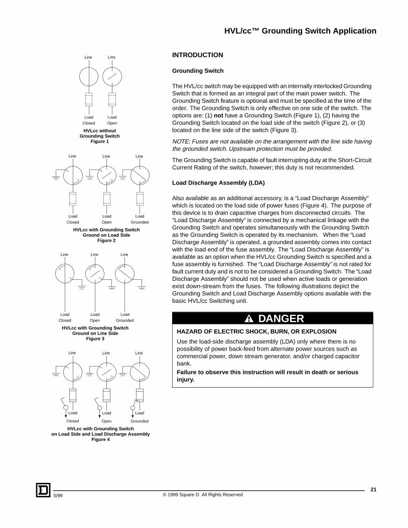
INTRODUCTION
Grounding Switc h
The HVL/cc switch may be equipped with an internally interlocked Grounding Switch that is formed as an integral part of the main power switch. The Grounding Switch feature is optional and must be specified at the time of the order. The Grounding Switch is only effective on one side of the switch. The options are: (1)
not
have a Grounding Switch (Figure 1), (2) having the Grounding Switch located on the load side of the switch (Figure 2), or (3) located on the line side of the switch (Figure 3).
NOTE: Fuses are not available on the arrangement with the line side having the grounded switch. Upstream protection must be provided.
The Grounding Switch is capable of fault interrupting duty at the Short-Circuit Current Rating of the switch, however; this duty is not recommended.
Load Disc harge Assemb ly (LDA)
Also available as an additional accessory, is a “Load Discharge Assembly” which is located on the load side of power fuses (Figure 4). The purpose of this device is to drain capacitive charges from disconnected circuits. The “Load Discharge Assembly” is connected by a mechanical linkage with the Grounding Switch and operates simultaneously with the Grounding Switch as the Grounding Switch is operated by its mechanism. When the “Load Discharge Assembly” is operated, a grounded assembly comes into contact with the load end of the fuse assembly. The “Load Discharge Assembly” is available as an option when the HVL/cc Grounding Switch is specified and a fuse assembly is furnished. The “Load Discharge Assembly” is not rated for fault current duty and is not to be considered a Grounding Switch. The “Load Discharge Assembly” should not be used when active loads or generation exist down-stream from the fuses. The following illustrations depict the Grounding Switch and Load Discharge Assembly options available with the basic HVL/cc Switching unit.
HAZARD OF ELECTRIC SHOCK, BURN, OR EXPLOSION
Use the load-side discharge assembly (LDA) only where there is no possibility of power back-feed from alternate power sources such as commercial power, down stream generator, and/or charged capacitor bank.
Failure to obser ve this instruction will result in death or serious injur y.
Line
Load
HVLcc withoutGrounding Switch
Figure 1
Closed
Line
Load
Open
HVLcc with Grounding SwitchGround on Load Side
Figure 2
Line
Load
Closed
Line
Load
Open
Line
Load
Grounded
HVLcc with Grounding SwitchGround on Line Side
Figure 3
Line
Load
Closed
Line
Load
Open
Line
Load
Grounded
Load
HVLcc with Grounding Switchon Load Side and Load Discharge Assembly
Figure 4
Closed
Load
Open
Load
Grounded
Line Line Line
DANGER
HVL/cc™ Grounding Switch Application
© 1999 Square D All Rights Reserved
22
5/99
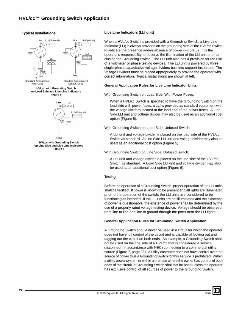
Live Line Indicator s (LLI unit)
When a HVL/cc Switch is provided with a Grounding Switch, a Live Line Indicator (LLI) is always provided on the grounding side of the HVL/cc Switch to indicate the presence and/or absence of power (Figure 5). It is the operator’s responsibility to observe the illumination of the LLI unit prior to closing the Grounding Switch. The LLI unit also has a provision for the use of a voltmeter or phase testing devices. The LLI unit is powered by three single-phase capacitative voltage dividers built into support insulators. The Voltage Dividers must be placed appropriately to provide the operator with correct information. Typical installations are shown at left.
General Application Rules f or Live Line Indicator Units
With Grounding Switch on Load Side, With Power Fuses:
When a HVL/cc Switch is specified to have the Grounding Switch on the load side with power fuses, a LLI is provided as standard equipment with the voltage dividers located at the load end of the power fuses. A Line Side LLI unit and voltage divider may also be used as an additional cost option (Figure 5).
With Grounding Switch on Load Side, Unfused Switch:
A LLI unit and voltage divider is placed on the load side of the HVL/cc Switch as standard. A Line Side LLI unit and voltage divider may also be used as an additional cost option (Figure 5).
With Grounding Switch on Line Side, Unfused Switch:
A LLI unit and voltage divider is placed on the line side of the HVL/cc Switch as standard. A Load Side LLI unit and voltage divider may also be used as an additional cost option (Figure 6).
Testing
Before the operation of a Grounding Switch, proper operation of the LLI units shall be verified. If power is known to be present and all lights are illuminated prior to the operation of the switch, the LLI units are considered to be functioning as intended. If the LLI units are not illuminated and the existence of power is questionable, the existence of power shall be determined by the use of a properly rated voltage testing device. Voltage should be observed from line to line and line to ground through the ports near the LLI lights.
General Application Rules f or Gr ounding Switc h Application
A Grounding Switch should never be used in a circuit for which the operator does not have full control of the circuit and is capable of locking out and tagging out the circuit on both ends. As example, a Grounding Switch shall not be used on the line side of a HVL/cc that is considered a service disconnect (in accordance with NEC) connecting to a commercial utility source (Figure 7, page 23). A utility customer does not have control over the source of power thus a Grounding Switch for this service is prohibited. Within a utility power system or within a premise where the owner has control of both ends of the circuit, a Grounding Switch shall not be used unless the operator has exclusive control of all sources of power to the Grounding Switch.
LLI
LLI (Optional)Line
Load
HVLcc with Grounding Switchon Load Side and Live Line Indicators
Figure 5
Standard Arrangementwith Fuses
LLI
Load
Standard Arrangementwithout Fuses
LLI (Optional)Line
LLI (Optional)
LLI
HVLcc with Grounding Switchon Line Side and Live Line Indicators
Figure 6
Line
Load
Line
Typical Installations
HVL/cc™ Grounding Switch Application
23
5/99 © 1999 Square D All Rights Reserved
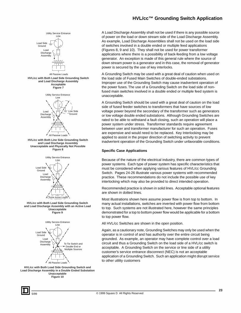
A Load Discharge Assembly shall not be used if there is any possible source of power on the load or down stream side of the Load Discharge Assembly. As example, Load Discharge Assemblies shall not be used on the load side of switches involved in a double ended or multiple feed applications (Figures 8, 9 and 10). They shall not be used for power transformer applications where there is a possibility of back-feeding from a low voltage generator. An exception is made of this general rule where the source of down stream power is a generator and in this case, the removal of generator power is secured by the use of key interlocks.
A Grounding Switch may be used with a great deal of caution when used on the load side of Fused Main Switches of double-ended substations. Improper use of the Grounding Switch may cause inadvertent operation of the power fuses. The use of a Grounding Switch on the load side of non-fused main switches involved in a double ended or multiple feed system is unacceptable.
A Grounding Switch should be used with a great deal of caution on the load side of fused feeder switches to transformers that have sources of low voltage power beyond the secondary of the transformer such as generators or low voltage double ended substations. Although Grounding Switches are rated to be able to withstand a fault closing, such an operation will place a power system under stress. Transformer standards require agreement between user and transformer manufacturer for such an operation. Fuses are expensive and would need to be replaced. Key Interlocking may be applied to assist in the proper direction of switching activity to prevent inadvertent operation of the Grounding Switch under unfavorable conditions.
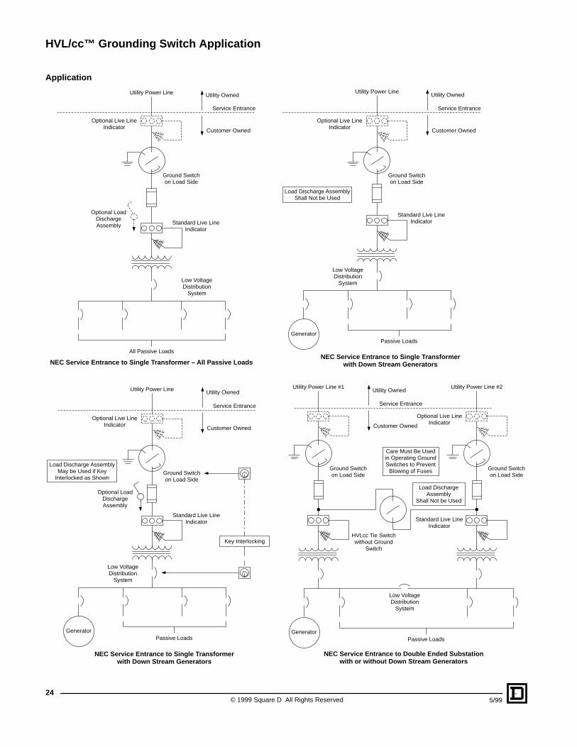
Specifi c Case Applications
Because of the nature of the electrical industry, there are common types of power systems. Each type of power system has specific characteristics that must be considered when applying various features of HVL/cc Grounding Switch. Pages 24-26 illustrate various power systems with recommended practice. These recommendations do not include the possible use of key interlocking which may also be provided to direct intended operation.
Recommended practice is shown in solid lines. Acceptable optional features are shown in dotted lines.
Most illustrations shown here assume power flow is from top to bottom. In many actual installations, switches are inverted with power flow from bottom to top. Such systems are not illustrated here, however the same principles demonstrated for a top to bottom power flow would be applicable for a bottom to top power flow.
All HVL/cc Switches are shown in the open position.
Again, as a cautionary note, Grounding Switches may only be used when the operator is in control of and has authority over the entire circuit being grounded. As example, an operator may have complete control over a load circuit and thus a Grounding Switch on the load side of a HVL/cc switch is acceptable. A Grounding Switch on the service or line side of a utility customer’s service entrance disconnect (NEC) is not an acceptable application of a Grounding Switch. Such an application might disrupt service to other utility customers
LoadDischargeAssembly
Utility Service EntranceLine
Load SideGround
All Passive Loads
HVL/cc with Both Load Side Grounding Switchand Load Discharge Assembly
AcceptableFigure 7
LoadDischargeAssembly
Utility Service EntranceLine
Line SideGround
All Passive Loads
HVL/cc with Both Line Side Grounding Switchand Load Discharge Assembly
Unacceptable and Physically Not PossibleFigure 8
LoadDischargeAssembly
Some Active Loads
Utility Service EntranceLine
Load SideGround
HVL/cc with Both Load Side Grounding Switchand Load Discharge Assembly with an Active Load
UnacceptableFigure 9
LoadDischargeAssembly
All Passive Loads
To Tie Switch andDouble End or
Multiple Sources
Utility Service EntranceLine
Load SideGround
HVL/cc with Both Load Side Grounding Switch andLoad Discharge Assembly in a Double Ended Substation
UnacceptableFigure 10
HVL/cc™ Grounding Switch Application
© 1999 Square D All Rights Reserved24
5/99
Applic ation
All Passive Loads
Low VoltageDistribution
System
Standard Live LineIndicator
Ground Switchon Load Side
Optional Live LineIndicator
Optional LoadDischargeAssembly
Utility Power Line Utility Owned
Customer Owned
Service Entrance
NEC Service Entrance to Single Transformer – All Passive Loads
Passive Loads
Low VoltageDistribution
System
Standard Live LineIndicator
Ground Switchon Load Side
Optional Live LineIndicator
Utility Power LineUtility Owned
Customer Owned
Service Entrance
Generator
Load Discharge AssemblyShall Not be Used
NEC Service Entrance to Single Transformer with Down Stream Generators
Passive Loads
Low VoltageDistribution
System
Standard Live LineIndicator
Ground Switchon Load Side
Optional Live LineIndicator
Utility Power Line Utility Owned
Customer Owned
Service Entrance
Generator
Load Discharge AssemblyMay be Used if Key
Interlocked as Shown
Optional LoadDischargeAssembly
Key Interlocking
NEC Service Entrance to Single Transformerwith Down Stream Generators
Passive Loads
HVLcc Tie Switchwithout Ground
Switch
Ground Switchon Load Side
Utility Power Line #1Utility Owned
Customer Owned
Service Entrance
Generator
Low VoltageDistribution
System
Standard Live LineIndicator
Ground Switchon Load Side
Optional Live LineIndicator
Utility Power Line #2
Load DischargeAssembly
Shall Not be Used
Care Must Be Usedin Operating GroundSwitches to Prevent
Blowing of Fuses
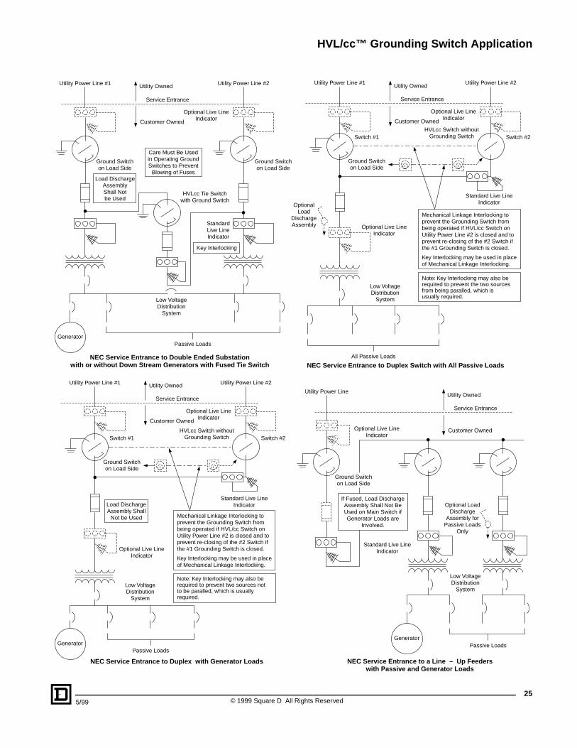
NEC Service Entrance to Double Ended Substationwith or without Down Stream Generators
HVL/cc™ Grounding Switch Application
255/99 © 1999 Square D All Rights Reserved
Passive Loads
HVLcc Tie Switchwith Ground Switch
Ground Switchon Load Side
Utility Power Line #1 Utility Owned
Customer Owned
Service Entrance
Generator
Low VoltageDistribution
System
StandardLive LineIndicator
Ground Switchon Load Side
Optional Live LineIndicator
Utility Power Line #2
Load DischargeAssemblyShall Notbe Used
Care Must Be Usedin Operating GroundSwitches to Prevent
Blowing of Fuses
Key Interlocking
NEC Service Entrance to Double Ended Substationwith or without Down Stream Generators with Fused Tie Switch
All Passive Loads
Low VoltageDistribution
System
Optional Live LineIndicator
Ground Switchon Load Side
OptionalLoad
DischargeAssembly
Utility Power Line #1
Optional Live LineIndicator
Utility Power Line #2Utility Owned
Customer Owned
Service Entrance
Switch #2Switch #1HVLcc Switch without
Grounding Switch
Standard Live LineIndicator
Mechanical Linkage Interlocking toprevent the Grounding Switch frombeing operated if HVL/cc Switch onUtility Power Line #2 is closed and toprevent re-closing of the #2 Switch ifthe #1 Grounding Switch is closed.
Key Interlocking may be used in placeof Mechanical Linkage Interlocking.
Note: Key Interlocking may also berequired to prevent the two sourcesfrom being paralled, which isusually required.
NEC Service Entrance to Duplex Switch with All Passive Loads
Passive Loads
Low VoltageDistribution
System
Optional Live LineIndicator
Ground Switchon Load Side
Utility Power Line #1
Optional Live LineIndicator
Utility Power Line #2Utility Owned
Customer Owned
Service Entrance
Switch #2Switch #1HVLcc Switch without
Grounding Switch
Standard Live LineIndicator
Mechanical Linkage Interlocking toprevent the Grounding Switch frombeing operated if HVL/cc Switch onUtility Power Line #2 is closed and toprevent re-closing of the #2 Switch ifthe #1 Grounding Switch is closed.
Key Interlocking may be used in placeof Mechanical Linkage Interlocking.
Note: Key Interlocking may also berequired to prevent two sources notto be paralled, which is usuallyrequired.
Generator
Load DischargeAssembly Shall
Not be Used
NEC Service Entrance to Duplex with Generator Loads
Passive Loads
Low VoltageDistribution
System
Standard Live LineIndicator
Optional Live LineIndicator
Optional LoadDischarge
Assembly forPassive Loads
Only
Utility Owned
Customer Owned
Service Entrance
Ground Switchon Load Side
Utility Power Line
Generator
If Fused, Load DischargeAssembly Shall Not BeUsed on Main Switch ifGenerator Loads are
Involved.
NEC Service Entrance to a Line – Up Feederswith Passive and Generator Loads
HVL/cc™ Grounding Switch Application
© 1999 Square D All Rights Reserved26
5/99
Low VoltageDistribution
System
Live Line Indicator(Required)Ground Switch
on Line Side
Ground Switchon Load Side
Line Circuit A
Standard Live LineIndicator
Live Line Indicator(Required)
Live Line Indicator(Required)
Ground Switchon Line Side
Line Circuit B
Care Must Be Used inOperating Ground
Switches to PreventLine Faults
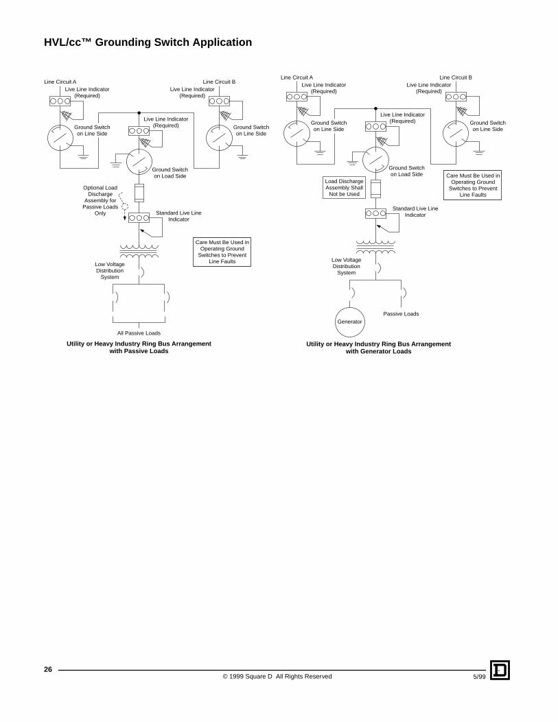
Utility or Heavy Industry Ring Bus Arrangementwith Passive Loads
Optional LoadDischarge
Assembly forPassive Loads
Only
All Passive Loads
Passive Loads
Low VoltageDistribution
System
Live Line Indicator(Required)Ground Switch
on Line Side
Ground Switchon Load Side
Line Circuit A
Standard Live LineIndicator
Live Line Indicator(Required)
Live Line Indicator(Required)
Ground Switchon Line Side
Line Circuit B
Generator
Care Must Be Used inOperating Ground
Switches to PreventLine Faults
Load DischargeAssembly Shall
Not be Used
Utility or Heavy Industry Ring Bus Arrangementwith Generator Loads
HVL/cc™ Grounding Switch Application
275/99 © 1999 Square D All Rights Reserved
Duple x Switc h Interloc king (see pa ge 16)
Because of the popularity of the Duplex Switch (two services for a common load), mechanical interlocking is provided between the two Switches. This mechanical interlocking directs the proper operation of the Grounding Switch for the Duplex style switch. The interlocking is arranged such that the Grounding Switch on the #1 Switch cannot be operated if the #2 Switch is closed. Also the interlocking will prevent the re-closing of the #2 Switch if the #1 Switch is in the Grounded position. This interlocking may be employed for other power systems other than Duplex Switches if required. This mechanical interlocking may be provided by either Key Interlocking or by direct mechanical linkage.
Key Interloc king
Key Interlocking is not shown in this application manual as an extensive requirement. It is only shown as an alternative to mechanical interlocking for the Duplex Switch and to enable the use of the LDA for systems having a generator supply source down stream. Key Interlocking may be used as an additional precaution and to assist the user in performing the proper operating sequence before switching operations. It is not the scope of this application section to cover all possible combinations of suitable key interlocking schemes. Each power system must be evaluated and appropriate key interlocking specified to meet particular risks a system may have. This process is typically performed by the Professional Engineer of Record for the facility. Key Interlocking may be applied considering the following general philosophy:
General Philosoph y
HVL/cc grounding switches are rated to withstand a full rated fault closure. It is considered an unreasonable risk to operate a power system in a manner that would stress the Grounding Switch to its rated capacity and subject the balance of the system including possible power transformers to needless fault currents. Whenever it is possible for a Grounding Switch to be operated in this mode, some mechanical means such as a mechanical interlock or key interlock will be provided by Square D to prevent the operator from inadvertently closing the Grounding Switch.
In a case where a Grounding Switch may be operated such that the fault current is limited by its own current limiting fuses, a mechanical or key interlock is not required because the fault current is significantly limited by the fuse. This exception is not applicable for non current limiting fuses or non fused HVL/cc devices. Since the LLI units are required, the operator must observe for the possibility of back-feeding and avoid the loss of the fuses. Ignoring the lighted LLI indictors can cause the loss of the current limiting fuses. However, the power system is not expected to be over-stressed even if proper procedures are not observed.
The Load Discharge Assemblies are to ensure that charges are drained from de-energized cables and down stream loads. If closed on any continuous source of power, significant damage will occur to the LDA and the HVL/cc. The use of the LDA is discouraged whenever there is any possibility of down stream power back-feeding (as discussed on page 23). They may be used in conjunction with on site generation if key interlocking is provided. Even key interlocking is sometimes compromised which in this case might cause significant damage to the LDA and risk to the operator. Key interlocking is considered acceptable for on site generators because under fault conditions a generator will produce limited, long term short circuit current, limiting the damage to the LDA. They should never be used where back-feeding may come from commercial sources.
Typical Control Circuit
© 1999 Square D All Rights Reserved28
5/99
–
–––
––
–
–
K2
521
K2
K2
M K2
B
A
To
To
ATo
ATo
5
6 and 10TBM
Close, Motor and TripVolts Common
1
2
D6 K1Y1
(TC)Y2
(CC)D2 D1
D3
517
1 4
R2
+
+ + –
+ ++
+
–
–
TBM
TBM
K1
K1
K1
516
52A5/a
510
4
1
1
4
13
13A
2
1
5144
1
5132
1
5152
1
5202
2
3
1
54A5/a
A5/a A5/b
4
1
4
1
2
1
4 2
1
BA3
2
2A
MotorVoltsTBM
5
1
CloseVoltsTBM
7
4
A5/a55
TBM15
11
BA
TBM
8
3
TripDevices
TBM9
6
TripVoltsTBM9A
7
1
2
F1
51
(OnDelays)
BA3
B
A
12
16TBM
1
4A5/b58
TBM13
9
10
14TBM
1
4A5/a56
TBM51
13
14
52TBM
1
4A5/b59
TBM53
15
16
54TBM
1
4A5/a53
TBM55
17
18
56TBM
1
4A5/b57
TBM57
19
20
58TBM
1
4GSI511
TBM–
21
22
–TBM
1
2GSI512
TBM–
23
24
–TBM
1
4BFI518
TBM–
25
26
–TBM
1
2BFI518
27
–TBM
1
4BFI519
Device Name
Device Terminal
ANSI Terminal
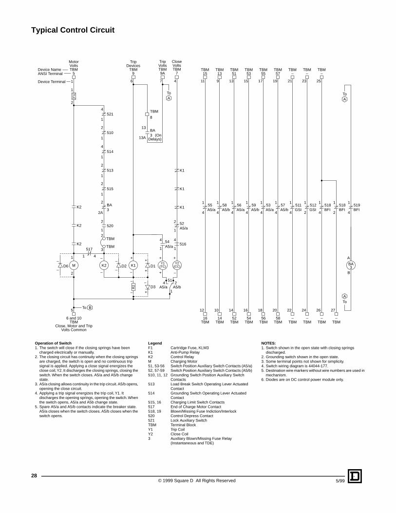
Operation of Switc h1. The switch will close if the closing springs have been
charged electrically or manually.2. The closing circuit has continuity when the closing springs
are charged, the switch is open and no continuous trip signal is applied. Applying a close signal energizes the close coil, Y2. It discharges the closing springs, closing the switch. When the switch closes. A5/a and A5/b change state.
3. A5/a closing allows continuity in the trip circuit. A5/b opens, opening the close circuit.
4. Applying a trip signal energizes the trip coil, Y1. It discharges the opening springs, opening the switch. When the switch opens, A5/a and A5b change state.
5. Spare A5/a and A5/b contacts indicate the breaker state. A5/a closes when the switch closes. A5/b closes when the switch opens.
LegendF1 Cartridge Fuse, KLM3K1 Anti-Pump RelayK2 Control RelayM Charging Motor51, 53-56 Switch Position Auxiliary Switch Contacts (A5/a)52, 57-59 Switch Position Auxiliary Switch Contacts (A5/b)510, 11, 12 Grounding Switch Position Auxiliary Switch
Contacts513 Load Break Switch Operating Lever Actuated
Contact514 Grounding Switch Operating Lever Actuated
Contact515, 16 Charging Limit Switch Contacts517 End of Charge Motor Contact518, 19 Blown/Missing Fuse Indiction/Interlock520 Control Depress Contact521 Lock Auxiliary SwitchTBM Terminal BlockY1 Trip CoilY2 Close Coil3 Auxiliary Blown/Missing Fuse Relay
(Instantaneous and TDE)
NOTES:1. Switch shown in the open state with closing springs
discharged.2. Grounding switch shown in the open state.3. Some terminal points not shown for simplicity.4. Switch wiring diagram is 44044-177.5. Destination wire markers without wire numbers are used in
mechanism.6. Diodes are on DC control power module only.
Optional Mechanism Features and Ratings
295/99 © 1999 Square D All Rights Reserved
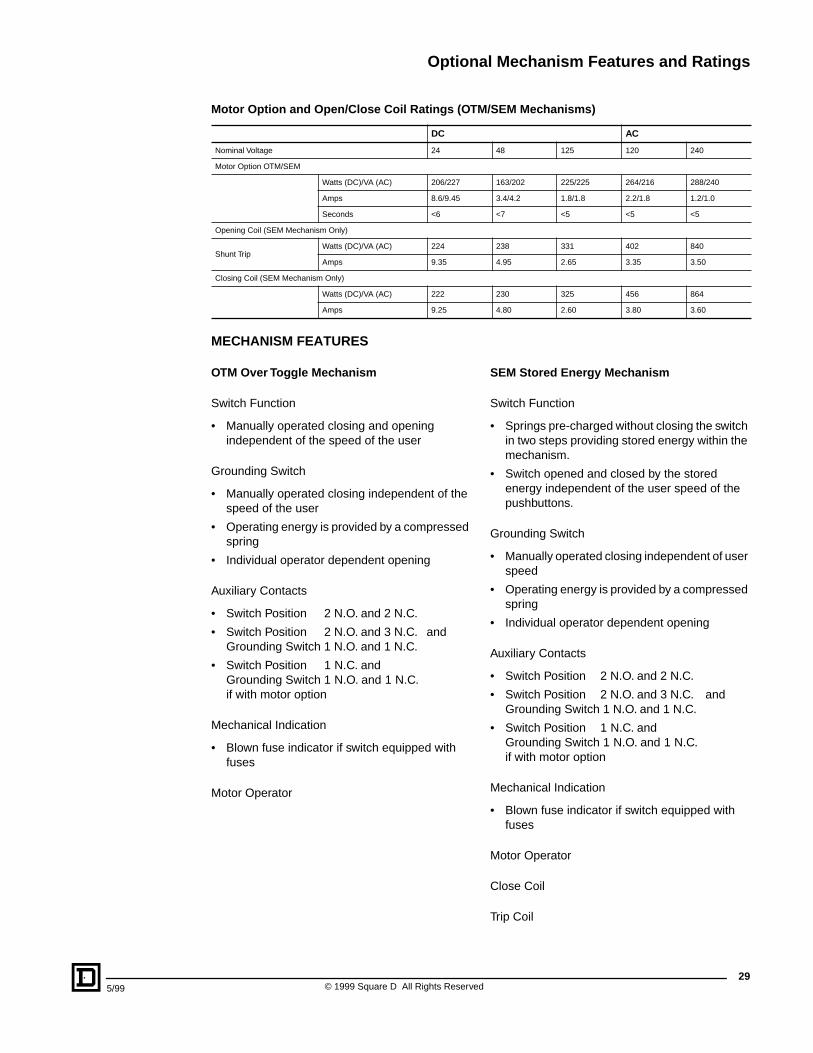
Motor Option and Open/Close Coil Ratings (O TM/SEM Mechanisms)
MECHANISM FEATURES
OTM Over Toggle Mec hanism
Switch Function
• Manually operated closing and opening independent of the speed of the user
Grounding Switch
• Manually operated closing independent of the speed of the user
• Operating energy is provided by a compressed spring
• Individual operator dependent opening
Auxiliary Contacts
• Switch Position 2 N.O. and 2 N.C.
• Switch Position 2 N.O. and 3 N.C. and Grounding Switch 1 N.O. and 1 N.C.
• Switch Position 1 N.C. and Grounding Switch 1 N.O. and 1 N.C. if with motor option
Mechanical Indication
• Blown fuse indicator if switch equipped with fuses
Motor Operator
SEM Stored Ener gy Mec hanism
Switch Function
• Springs pre-charged without closing the switch in two steps providing stored energy within the mechanism.
• Switch opened and closed by the stored energy independent of the user speed of the pushbuttons.
Grounding Switch
• Manually operated closing independent of user speed
• Operating energy is provided by a compressed spring
• Individual operator dependent opening
Auxiliary Contacts
• Switch Position 2 N.O. and 2 N.C.
• Switch Position 2 N.O. and 3 N.C. and Grounding Switch 1 N.O. and 1 N.C.
• Switch Position 1 N.C. and Grounding Switch 1 N.O. and 1 N.C. if with motor option
Mechanical Indication
• Blown fuse indicator if switch equipped with fuses
Motor Operator
Close Coil
Trip Coil
DC AC
Nominal Voltage 24 48 125 120 240
Motor Option OTM/SEM
Watts (DC)/VA (AC) 206/227 163/202 225/225 264/216 288/240
Amps 8.6/9.45 3.4/4.2 1.8/1.8 2.2/1.8 1.2/1.0
Seconds <6 <7 <5 <5 <5
Opening Coil (SEM Mechanism Only)
Shunt TripWatts (DC)/VA (AC) 224 238 331 402 840
Amps 9.35 4.95 2.65 3.35 3.50
Closing Coil (SEM Mechanism Only)
Watts (DC)/VA (AC) 222 230 325 456 864
Amps 9.25 4.80 2.60 3.80 3.60

6045CT9801 May 1999 © 1999 Square D All Rights Reserved.
Square D, , and PowerLogic are registered trademarks of Square D Company or related companies. HVL/cc and FUSELOGIC are trademarks of Square D Company or related companies.All other trademarks are the intellectual property of their respective companies.
Square D Company330 Weakley RoadSmyrna, TN 37167(615) 459-5026www.squared.com