Embed Size (px)
Citation preview

meteocontrol Power Control
Operating Manual
Version 20131213

meteocontrol Power Control
Copyright
Copyright for this manual remains with the manufacturer. No part of this manual may
be reproduced or edited, duplicated or distributed using electronic systems without
written permission from meteocontrol GmbH.
Compensation shall be payable in the event of any copyright infringements.
All brand names mentioned in this manual are the property of their respective
manufacturers and are hereby acknowledged.
Contact data
The manufacturer of the device described in this documentation is:
meteocontrol GmbH
Spicherer Str. 48
D-86157 Augsburg
Tel.: +49 (0) 821 / 3 46 66-0
Web: www.meteocontrol.de
Technical support:
Tel.: +49 (0) 821 / 3 46 66-88
Fax: +49 (0) 821 / 3 46 66-11
E-mail: [email protected]
Details regarding the manual
The original operating manual is written in German. All other language versions are
translations of the original operating manual and are hereby identified as such.
© 2013 meteocontrol GmbH
All rights reserved.
All information in this operating manual has been compiled and checked with the
greatest care and diligence. Nevertheless, the possibility of errors cannot be entirely
excluded. meteocontrol GmbH therefore cannot accept any liability for errors or any
circumstances resulting from errors.
Subject to technical alterations.

meteocontrol Power Control 1| 34
Contents 1. General notes ..............................................................................................................2
1.1 Safety instructions ............................................................................................... 2 1.2 Warning symbols ................................................................................................. 2 1.3 Additional information .......................................................................................... 2 1.4 Text display .......................................................................................................... 3
2. Notes on using the operating manual ...........................................................................4 2.1 Warranty and liability ............................................................................................ 5
3. Technical description ...................................................................................................6 3.1 Grid feed-in management requirements ............................................................... 6 3.2 meteocontrol Power Control requirements .......................................................... 6 3.3 meteocontrol Power Control functionality ............................................................ 7 3.4 Power Control Unit functionality ........................................................................... 7 3.5 Power Control with PCU+ functionality ................................................................ 8 3.6 Power Control without PCU+ functionality ........................................................... 9 3.7 Functions ........................................................................................................... 10
4. Power Control device configuration ............................................................................ 11
5. meteocontrol Power Control configuration.................................................................. 11 5.1 WEB’log definition as master ............................................................................. 11 5.2 WEB`log definition as slave ................................................................................ 12 5.3 Power Control system data ................................................................................ 13 5.4 Power control procedures for the meteocontrol Power Control ......................... 14 5.5 Active power procedure ..................................................................................... 18 5.5.1 P(DI) ................................................................................................................... 18 5.5.2 P(AI) ................................................................................................................... 19 5.5.3 P Fix ................................................................................................................... 20 5.5.4 P(DI) internal ...................................................................................................... 20 5.6 Reactive power procedure ................................................................................. 21 5.6.1 Cosφ (DI) ............................................................................................................ 21
5.6.2 Cosφ (AI) ............................................................................................................ 22 5.6.3 Cosφ Fix ............................................................................................................. 23 5.6.4 Cosφ (P) ............................................................................................................. 23 5.6.5 Cosφ (U) ............................................................................................................. 24 5.6.6 Q(DI) .................................................................................................................. 25 5.6.7 Q(AI) ................................................................................................................... 26 5.6.8 Q fix ................................................................................................................... 27 5.6.9 Q(U) ................................................................................................................... 27 5.6.10 Inverter cosφ (P) ................................................................................................. 28 5.6.11 Inverter Q(U) ...................................................................................................... 28 5.7 Enabling Power Control ...................................................................................... 29 5.8 Power Control status.......................................................................................... 29 5.9 Power Control settings via the data logger display ............................................. 30
6. Power quality analyser ............................................................................................... 31
7. Grid feed-in management overview ............................................................................ 32
8. List of figures ............................................................................................................ 33

2| 34 meteocontrol Power Control
1. General notes
1.1 Safety instructions
Safety instructions warn of dangers when using the devices and explain how they can
be avoided.
The safety instructions are classified according to the severity of the risk and are
subdivided into three groups:
DANGER
Imminent danger
– Failure to comply with the warning notice will lead to an imminent risk of death
or serious physical injury!
WARNING
Possible danger
– Failure to comply with the warning notice may lead to a risk of death or serious
physical injury!
CAUTION
Hazard with a risk of material damage
– Failure to comply with the warning notice may lead to minor injuries!
ATTENTION
Hazard with a risk of material damage
– Failure to comply with the warning notice will lead to material damage!
1.2 Warning symbols
Particular dangers are highlighted using warning symbols.
RISK OF ELECTRIC SHOCK
Electric shock hazard! Danger to life and limb!
– Failure to comply with the warning notice will lead to an imminent risk of
serious injury or death.
1.3 Additional information
This symbol can be found next to notes, additional information and tips.

meteocontrol Power Control 3| 34
1.4 Text display
Emphasised points are shown in bold and indicate important information.
Lists are shown with bullet points (level 1) and dashes (level 2):
List 1
Point A
Point B
List 2
Instructions describe steps which are to be carried out in the given order.
1. Instruction 1
2. Instruction 2
Result of the operation
Button names are shown in capitals and in "QUOTATION MARKS".
In figures, item numbers are used to indicate components.
The legend with item numbers and descriptions of the components are shown below
the figure. Alternatively, direct references to components are made in the text.

4| 34 meteocontrol Power Control
2. Notes on using the operating manual This description is designed to ensure that the WEB’log, PCU and PCU+ devices
function properly. It contains important information and safety notes to help you use
the devices correctly, economically and in the intended manner.
The description helps to avoid dangers, to reduce repair costs and downtimes, and to
increase the reliability and operating life of the devices.
This operating manual describes the additional Power Control functions and,
specifically, the power control procedures.
DANGER
Danger owing to improper handling of the devices
- The staff responsible for the installation, operation and maintenance of the
system must have read and understood this operating manual before the
devices can be configured and used safely!
- If necessary, the description and documents must be available at all times.
meteocontrol GmbH accepts no liability for personal injury, damage to property, or
system malfunctions and their consequences, insofar as these result from non-
observance of this operating manual.
The manual is continually updated. The most up-to-date version of this description can
be found on our internet page www.meteocontrol.de
meteocontrol Power Control 5| 34
2.1 Warranty and liability
Details of the scope and form of the warranty as well as the warranty period are given
in the meteocontrol GmbH General Terms and Conditions.
meteocontrol rejects any liability for damage arising from the non-observance of the
operating manual.
This applies, in particular, for damage from:
Unintended use
Faulty operation
Wrongly chosen materials and tools
Faulty or non-executed maintenance and repairs
With Power Control, meteocontrol GmbH accepts no liability for events and
occurrences outside of its control, such as:
the correctness of control commands given by an energy supply company or failure
to implement control commands that have been passed on
hardware and/or software faults on the part of the system operator
switching processes on consumer end.
Any liability for damage caused by such events and occurrences, such as lost
profits, grid instability, damage to parts of the customer's system, for instance of an
inverter, shall remain expressly excluded.

6| 34 meteocontrol Power Control
3. Technical description Power Control is a system for controlling and managing different operating parameters
of PV systems (such as reactive and active power).
3.1 Grid feed-in management requirements
As the proportion of solar power in relation to overall power production increases, it
becomes increasingly necessary for PV system operators to become actively involved
in grid feed-in management. This means it must be possible to reduce feed-in power
and play a role in compensating for the reactive power in the grid as stipulated in the
EEG (German Renewable Energy Law), the Medium Voltage Directive, the
Transmission Code and VDE AR-N 4105.
In view of this, the system operators must fulfil the following requirements:
They must be able to reduce the feed-in power of systems by remote control or
disconnect systems from the grid entirely.
They must be able to reduce the reactive power in the grid by reactive power
compensation.
3.2 meteocontrol Power Control requirements
It is recommended that you clarify the following requirements of the grid operator,
inverter manufacturer and system operator for Power Control in the system planning
phase:
Procedures according to which the requirements of the grid operator are
implemented, resulting in control values for the inverters.
Procedures that are supported by the WEB`log for the inverter types used
(inverter drivers).
Interfaces used for the grid operator's remote control and monitoring systems.
Characteristic requirements for the power control mechanism made by the
system operator:
If difficulties regarding these requirements arise or the necessary configuration
options are not available, consult your meteocontrol contact in sales or system
planning/system start-up.

meteocontrol Power Control 7| 34
3.3 meteocontrol Power Control functionality
Basic function:
The requirements for power reduction and control are given by the grid operator
and carried out via a selected interface (digital, analogue) by the PCU, PCU+ or
WEB`log inputs.
The control values are determined from the requirements in accordance with
configurable rules. The rules can be defined in accordance with the requirements.
Feedback to the grid operator is optionally provided.
The control values are set on the inverter within a response time as required by the
grid operator.
The grid operator receives a message about the control value set on the inverters.
3.4 Power Control Unit functionality
The Power Control Unit (PCU) and the Power Control Unit + (PCU+) are intelligent,
high-performance modules which expand the functions of the WEB‘log by adding
reactive power control.
This ensures efficient control of the active and reactive power in photovoltaic systems.
General function:
The PCU receives the requirements from the grid operator's remote control and
monitoring system via its inputs.
The PCU prepares the requirements and forwards them to the WEB`log.
The WEB`log establishes the control values and sends them to the inverters.
No PCU is required to achieve a reduction in active power via four potential-free
contacts and without feedback to the grid operator. The corresponding procedures
(referred to as P(DI) internal and P (fix)) can be implemented with the WEB’logs
BASIC, LIGHT+ 20 and PRO unlimited via the digital inputs.
Likewise, no PCU is required for reactive power procedures defined via a characteristic
curve.
On the following pages, meteocontrol Power Control functions are presented with and
without a PCU. The way in which the requirements for active and reactive power
issued by the grid operator reach the inverters is depicted clearly.

8| 34 meteocontrol Power Control
3.5 Power Control with PCU+ functionality
Fig. 1: PCU<->Power Control functionality
(1) Grid operator (7) WEB`log PRO as slave
(2) Public grid (8) Inverter
(3) Ripple control receiver (9) Internet
(4) Power Control Unit (PCU) (10) Web portal
(5) WEB`log PRO as master (11) Power requirements report
(6) Ethernet switch

meteocontrol Power Control 9| 34
3.6 Power Control without PCU+ functionality
Fig. 2: Power Control functionality
(1) Grid operator (6) WEB`log slave
(2) Public grid (7) Inverter
(3) Ripple control receiver (8) Internet
(4) WEB`log master (9) Web portal
(5) Ethernet switch (10) Power requirements report

10| 34 meteocontrol Power Control
3.7 Functions Power control
Active power procedure (P procedure)
With the internal inputs of the WEB`log PRO unlimited, only the active
power procedure can be carried out via digital requirements.
Active and reactive power procedures (P/Q/cosφ procedures)
With the PCU, various active and reactive power procedures can be
selected and configured.
Master functions
In larger systems with several WEB`log PRO Unlimited devices, a WEB`log
assumes the master function.
The master receives the requirement values from the grid operator. The
information is forwarded to all WEB`log slaves or to the configured IP addresses
in the form of a broadcast via the Ethernet.
Power requirements change message
When changing the power requirements, the WEB`log PRO Unlimited
informs one or more recipients via the reporting route configured. The
message contains information on the time of changing and the required
power level.

meteocontrol Power Control 11| 34
4. Power Control device configuration Configuration of the Power Control Unit is carried out on the WEB’log websites. The
PCU configuration website is used to configure the Power Control Unit required for the
majority of power control procedures of the meteocontrol Power Control. The site can
be accessed via the menu item Admin Measurement > Power Control > PCU
Configuration.
For the corresponding configuration settings, please see the respective PCU or PCU+
operating manual. Up-to-date versions of the operating manuals are available for
downloading on our website.
5. meteocontrol Power Control configuration Configuration of the power control procedures of the meteocontrol Power Control is
carried out on the WEB’log websites. First, a computer must be connected to the
WEB'log via Ethernet. Afterwards the WEB'log home page can be addressed in the
web browser. Use the selection "Professional mode" and you log in to the admin area
via the General > Login menu. The standard password is: “ist02“.
The configuration is now carried out in the Admin Measurement > Power Control >
General Configuration menu. The individual steps are listed in order so that they can be
carried out consecutively.
5.1 WEB’log definition as master
With this selection, the WEB’log master defines the power control procedures and, if
desired, sends the parameters to the WEB’log slaves. The following figures show the
possible settings for the master:
Fig. 3: WEB`log master with broadcast to all slaves
Fig. 4: WEB`log master without slaves
Fig. 5: WEB`log master with slave groups
12| 34 meteocontrol Power Control
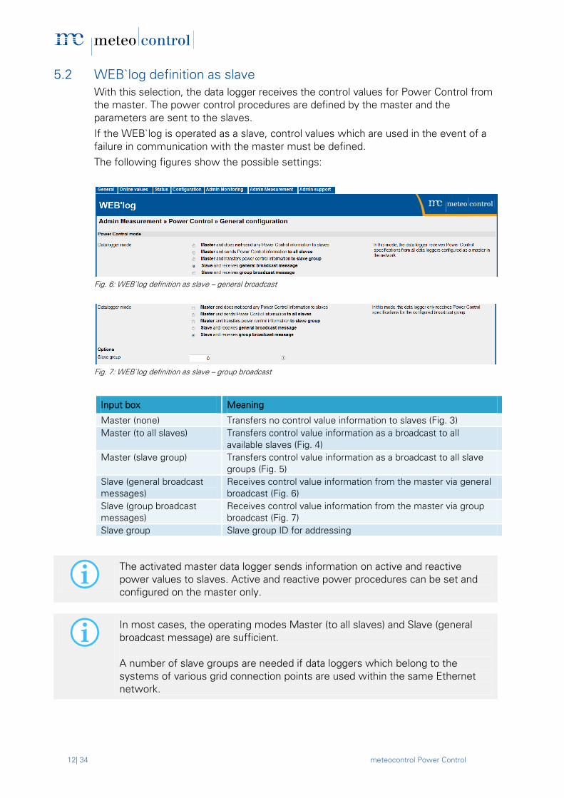
5.2 WEB`log definition as slave
With this selection, the data logger receives the control values for Power Control from
the master. The power control procedures are defined by the master and the
parameters are sent to the slaves.
If the WEB`log is operated as a slave, control values which are used in the event of a
failure in communication with the master must be defined.
The following figures show the possible settings:
Fig. 6: WEB`log definition as slave – general broadcast
Fig. 7: WEB`log definition as slave – group broadcast
Input box Meaning
Master (none) Transfers no control value information to slaves (Fig. 3)
Master (to all slaves) Transfers control value information as a broadcast to all
available slaves (Fig. 4)
Master (slave group) Transfers control value information as a broadcast to all slave
groups (Fig. 5)
Slave (general broadcast
messages)
Receives control value information from the master via general
broadcast (Fig. 6)
Slave (group broadcast
messages)
Receives control value information from the master via group
broadcast (Fig. 7)
Slave group Slave group ID for addressing
The activated master data logger sends information on active and reactive
power values to slaves. Active and reactive power procedures can be set and
configured on the master only.
In most cases, the operating modes Master (to all slaves) and Slave (general
broadcast message) are sufficient.
A number of slave groups are needed if data loggers which belong to the
systems of various grid connection points are used within the same Ethernet
network.
meteocontrol Power Control 13| 34
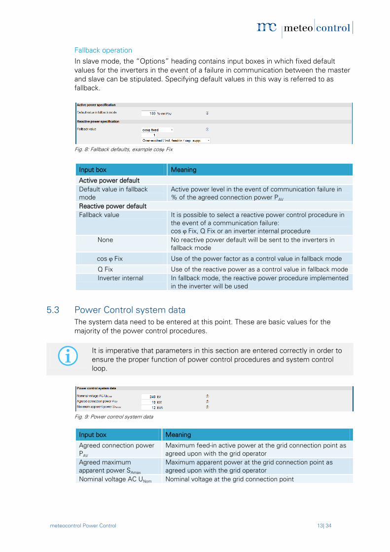
Fallback operation
In slave mode, the “Options” heading contains input boxes in which fixed default
values for the inverters in the event of a failure in communication between the master
and slave can be stipulated. Specifying default values in this way is referred to as
fallback.
Fig. 8: Fallback defaults, example cosφ Fix
Input box Meaning
Active power default
Default value in fallback
mode
Active power level in the event of communication failure in
% of the agreed connection power PAV
Reactive power default
Fallback value It is possible to select a reactive power control procedure in
the event of a communication failure:
cos φ Fix, Q Fix or an inverter internal procedure
None No reactive power default will be sent to the inverters in
fallback mode
cos φ Fix Use of the power factor as a control value in fallback mode
Q Fix Use of the reactive power as a control value in fallback mode
Inverter internal In fallback mode, the reactive power procedure implemented
in the inverter will be used
5.3 Power Control system data
The system data need to be entered at this point. These are basic values for the
majority of the power control procedures.
It is imperative that parameters in this section are entered correctly in order to
ensure the proper function of power control procedures and system control
loop.
Fig. 9: Power control system data
Input box Meaning
Agreed connection power
PAV
Maximum feed-in active power at the grid connection point as
agreed upon with the grid operator
Agreed maximum
apparent power SAmax
Maximum apparent power at the grid connection point as
agreed upon with the grid operator
Nominal voltage AC UNom Nominal voltage at the grid connection point

14| 34 meteocontrol Power Control
5.4 Power control procedures for the meteocontrol Power Control
The WEB’log PRO Unlimited is able to use a whole range of different procedures for
controlling the power of your PV system. However, an additional PCU, PCU+ and/or a
power quality analyser must be used for the more extensive procedures.
The active and reactive power procedures selected determine the processing type of
the requirements received.
Various procedures with different control values are brought together under
these active and reactive power procedures. Select the relevant procedure
according to the requirements.
The various procedures cannot use any control value sources or be combined at will.
A procedure for active power reduction can be selected without adding a procedure
for reactive power control. (Selecting the procedure for reactive power control is
optional).
A procedure for reactive power control can only be selected if a procedure for active
power reduction was chosen (selecting the procedure for active power reduction is
required).
An individual input screen for selecting parameters for the particular procedures
selected is displayed.
Normal operation
In normal operation,
control values are determined and sent to the inverters,
changes to the requirements are logged and
a notification is sent when changing the active power reduction (if notification is
configured) from the requirements in accordance with the defined rules.
Fallback operation
In the event of a communication failure between PCU and WEB`log or master and
slave WEB‘log, i.e. if no default values are received at that time, fallback operation
becomes active after a delay period of 10 minutes. In this case, the pre-configured
default values will be used during fallback. During the delay period, the parameter set
of the last valid control values is used.
If Power Control is enabled with the set of required information being incomplete,
fallback operation will likewise be enabled immediately.
Possible causes:
Error when receiving the requirements (digital-in or analogue-in).
Error in the definition of the configuration for the power procedures chosen.
Communication error between PCU and WEB`log master

meteocontrol Power Control 15| 34
Setting up the power control procedures
Fig. 10: Active power and reactive power procedures
Input box Meaning
Active power default
Active power procedure Active power procedure selection
Capping at PAV When this option is selected, the data logger ensures the
agreed connection power PAV is not exceeded.
Default value in fallback
mode
Default value for active power in fallback mode
Reactive power default
Procedure switching Enables switching between various reactive power
procedures via the digital inputs
Reactive power procedure Reactive power procedure selection
Q procedure
gradient limitation
Enables gradient limitation
The maximum permitted reactive power change per second
can be specified
cos φ (Fix) default value in
fallback mode
Default value for power factor in fallback mode
Q (Fix) default value in
fallback mode
Default value for reactive power in fallback mode
Configuration Brings up the configuration settings for the selected active
and reactive power procedure
A description of all power control procedures and the relevant settings can be
found in Chapters 5.5 and 5.6.

16| 34 meteocontrol Power Control
System control loop
The system control procedure ensures that inconsistencies in the power fed-in,
caused by the transmission route between the inverter and grid connection point
(GCP), are compensated (low voltage or medium voltage). As a result, the
requirements imposed by the grid operator are met at the GCP itself.
The GCP controlling procedure is only active if the reactive power procedure is
selected.
For correct functionality of the system control loop, the following parameters must be
entered correctly.
Agreed connection power PAV [kW]
Agreed maximum apparent power SAmax [kVA]
Nominal voltage AC UNom [kV]
Parameter model [transformer / no transformer] *
Transformer nominal power [kVA] *
Lower Plimit [%]
Lower cosφlimit *
Upper Qlimit [%] *
The "Upper Qlimit" field automatically generates its contents from the "Lower
cosφlimit" field and vice versa.
Therefore it is sufficient to enter the data provided by the inverter manufacturer
in one of the two fields. Once the cursor leaves the field or if the enter key is
pressed, the relevant other field is updated as well.
The following data also has to be entered under Configuration > System Data:
Installed power [kW] *
ATTENTION
- All data must be entered correctly. The parameters marked with * are
particularly important when it comes to ensuring correct control.
- Incorrectly entered data or values outside the technically feasible range of
the inverter(s) will result in control malfunctions.

meteocontrol Power Control 17| 34
Fig. 11: GCP control loop configuration
Input box Meaning
System control loop Activates the system control loop
Parameter model Selection of the parameter model to calculate the start
configuration control loop
Transformer nominal
power
Nominal power of the transformer
Lower Plimit Work threshold of the NAP control loop
Lower cos φlimit Work threshold of the NAP control loop
Upper Qlimit Work threshold of the NAP control loop
Generate start
configuration
Generate the start configuration for the GCP control loop
A power quality analyser at the grid connection point is essential for the
operation of the system control loop. Information regarding power quality
analysers can be found in Chapter 6.

18| 34 meteocontrol Power Control
5.5 Active power procedure
5.5.1 P(DI)
With this procedure, the active power P is used as the control value.
The default value is provided by the grid operator as a digital input signal. This is
possible for example via a ripple control receiver connected to the digital inputs of the
PCU. The reduction levels are assigned to the digital inputs via a parameter table. In
this case, every digital PCU input corresponds to a default value.
Feedback regarding reduction is provided via the digital outputs of the PCU.
Only individual outputs of the ripple control receiver may be assigned. Bit
samples (e.g. DI 1,2,4 = Adr. 007 for assigning the default value) are not
permitted.
In contrast, the P(DI) internal procedure allows bit samples.
Fig. 12: Active power procedure – P(DI) control
Input box Meaning
Number Control number
Active Setting whether the rule should be applied
Input Number of the IO port
Output Number of the IO port
P% Relative active power in percent (in relation to PAV)

meteocontrol Power Control 19| 34
5.5.2 P(AI)
With this procedure, the active power P is used as the control value.
The default value is provided by the grid operator as an analogue input signal. This is
possible for example via a remote control system with analogue outputs connected to
the analogue input (4–20 mA current signal in accordance with DIN IEC 60381-1) of the
PCU. Feedback is provided via the analogue output (4-20 mA current signal in
accordance with DIN IEC 60381-1).
The power reduction from the analogue value is calculated via a linear equation. For
the configuration, the value pairs P1 and P2 are required, which are at the end of the
line (min and max).
Fig. 13: Active power procedure – P(AI) control
Input box Meaning
AI Number of the analogue input
The lowest measured
value
Value pair for defining the lowest operating point (example: 4
mA corresponds to zero percent)
The highest measured
value
Value pair for defining the highest operating point (example: 20
mA corresponds to one hundred percent)
Sensitivity Point from when a change in the analogue input results in a
change in the control value (given in %)
20| 34 meteocontrol Power Control
5.5.3 P Fix
With this procedure, a fixed active power limit is used as the control value. To this end,
a configurable, consistent value is saved. With this procedure, a downward inverter
regulation to 70% or 60% for example is possible.
A PCU is not required for this procedure.
Feedback on the set power level is not possible with this procedure.
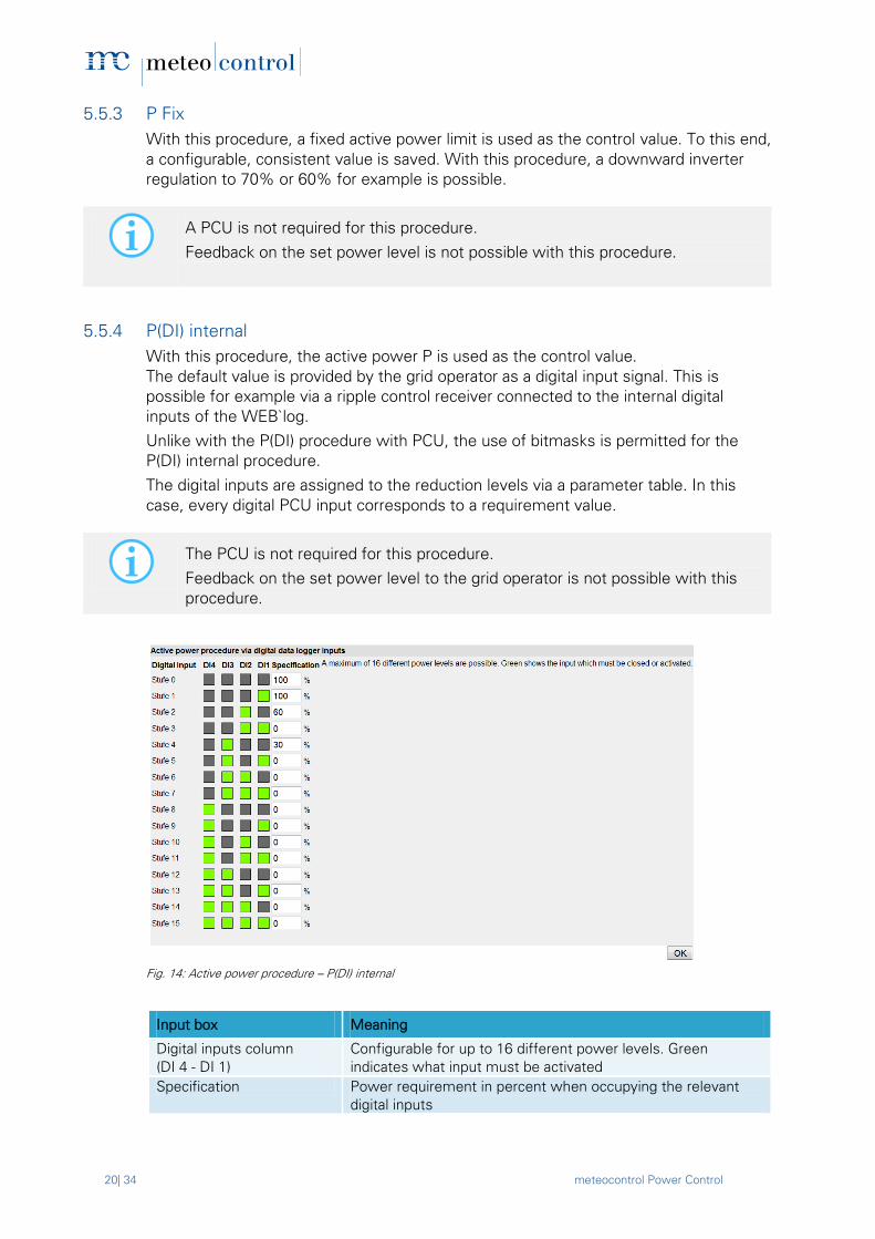
5.5.4 P(DI) internal
With this procedure, the active power P is used as the control value.
The default value is provided by the grid operator as a digital input signal. This is
possible for example via a ripple control receiver connected to the internal digital
inputs of the WEB`log.
Unlike with the P(DI) procedure with PCU, the use of bitmasks is permitted for the
P(DI) internal procedure.
The digital inputs are assigned to the reduction levels via a parameter table. In this
case, every digital PCU input corresponds to a requirement value.
The PCU is not required for this procedure.
Feedback on the set power level to the grid operator is not possible with this
procedure.
Fig. 14: Active power procedure – P(DI) internal
Input box Meaning
Digital inputs column
(DI 4 - DI 1)
Configurable for up to 16 different power levels. Green
indicates what input must be activated
Specification Power requirement in percent when occupying the relevant
digital inputs

meteocontrol Power Control 21| 34
5.6 Reactive power procedure
5.6.1 Cosφ (DI)
With this procedure, the power factor cosϕ is used as the control value. The default
value is provided by the grid operator as a digital input signal. This is possible for
example via a remote control system with digital outputs connected to the digital
inputs of the PCU.
Feedback is then provided via the digital outputs of the PCU.
The assignment is carried out via a parameter table. The breakdown and assignment of
the levels are freely selectable. In doing so, every digital PCU input corresponds to a
requirement value.
Fig. 15: Reactive power procedure – cosφ (DI)
Input box Meaning
Number Control number
Active Setting whether the rule should be applied
Input Number of the IO port
Output Number of the IO port
cos φ / excitation Power factor control values for reactive power reduction

22| 34 meteocontrol Power Control
5.6.2 Cosφ (AI)
With this procedure, the power factor cos ϕ is used as the control value. The default
value is provided by the grid operator as an analogue input signal. This is possible for
example via a remote control system with analogue outputs connected to the
analogue input of the PCU.
Feedback can be provided via the analogue output of the PCU.
The value is provided by the grid operator as an analogue input signal (4 – 20mA).
The power factor is calculated from the analogue value via a linear equation. For the
configuration, the value pairs P1 and P2 are required, which are at the end of the line.
Furthermore, the excitation type per point is required.
Fig. 16: Example cosφ (AI) characteristic curve
Fig. 17: Reactive power procedure – cosφ (AI) control
Input box Meaning
AI Number of the analogue input
The lowest measured
value
Indicated in mA and %. Value pair for defining the lowest
operating point (example: 4mA corresponds to factor 0.95 –
overexcited)
Highest measurement
value
Indicated in mA and %. Value pair for defining the highest
operating point (example: 20mA corresponds to factor 0.95 –
under- excitated)
Sensitivity Sensitivity setting: indicates from when a change to the
analogue input results in a change to the control value

meteocontrol Power Control 23| 34
5.6.3 Cosφ Fix
With this procedure, a fixed power factor cosϕ is used as the control value. To this
end, a configurable, consistent value is saved. No feedback is provided.
The PCU is not required for this procedure.
Feedback on the set power level is not possible with this procedure.
5.6.4 Cosφ (P)
With this procedure, the power factor cosφ is used as the control value. By changing
the power factor, it is possible to influence the power fed-in at the grid connection
point. Here the selected measuring device records the active power (P) fed-in at the
grid connection point and transfers it to the data logger, which then assigns the cosφ
control value to the relevant power on the basis of a 4 point characteristic curve.
The following details are required for the configuration:
The 4 characteristic points P1 to P4 of the characteristic curve
Details of the areas in which the points lie (overexcited or under- excitated)
Fig. 18: Reactive power procedure – cosφ (P) control
Input box Meaning
Curve Type of curve
Point 1…4 Support points 1…4
PHyst Hysteresis as the ratio of P/PAV
The PCU is not required for this procedure.
Feedback on the set power level is not possible with this procedure.
This procedure requires a power quality analyser that has been configured and
connected to the data logger.

24| 34 meteocontrol Power Control
5.6.5 Cosφ (U)
With this procedure, the power factor cosϕ is used as the control value. By changing
the power factor, it is possible to influence the voltage at the grid connection point. To
do this, the voltage U at the grid connection point is recorded by the selected
measuring device and transferred to the data logger, which then assigns the cosφ
control value to the relevant voltage on the basis of a linear equation.
The following details are required for the configuration:
The 4 points P1 to P4 of the characteristic curve
Details in what areas the points are (overexcited or under- excitated)
Fig. 19: Reactive power procedure – cosφ (U) control
Input box Meaning
Curve Type of curve
Point 1…4 Support points 1…4
UHyst Hysteresis as the ratio of U/UNom
The PCU is not required for this procedure.
Feedback on the set power level is not possible with this procedure.
This procedure requires a power quality analyser that has been configured and
connected to the data logger.

meteocontrol Power Control 25| 34
5.6.6 Q(DI)
With this procedure, the reactive power Q is used as the control value. The default
value is provided by the grid operator as a digital input signal, which is possible for
example via a remote control system with digital outputs connected to the digital
inputs of the PCU.
Feedback is provided via the digital outputs of the PCU.
The assignment is carried out via a parameter table. The breakdown and assignment of
the levels are freely selectable. In doing so, every digital PCU input corresponds to a
requirement value.
Fig. 20: Reactive power procedure – Q(DI) control
Input box Meaning
Number Control number
Active Setting whether the rule should be applied
Input Number of the IO port
Output Number of the IO port
Q(%) / excitation Reactive power control value for reactive power reduction in
percent

26| 34 meteocontrol Power Control
5.6.7 Q(AI)
With this procedure, the reactive power Q is used as the control value.
The default value is provided by the grid operator as an analogue input signal, which is
possible for example via a remote control system with analogue outputs connected to
the analogue input of the PCU.
Feedback is provided via an analogue output of the PCU.
The value is provided by the grid operator as an analogue input signal (typically: 4–
20mA). The reactive power is calculated from the analogue value via a linear equation.
The following details are required for the configuration:
The value pairs P1 and P2, which are at the end of the line (min and max).
Details in what areas the points are (overexcited or under-excitated)
Fig. 21: Q(AI) characteristic curve
Fig. 22: Reactive power procedure – Q(AI) control
Input box Meaning
AI Number of the analogue input
The lowest measured
value
Indicated in mA and %. Value pair for defining the lowest
operating point (example: 4 mA corresponds to 15 % -
overexcited)
The highest measured
value
Indicated in mA and %. Value pair for defining the highest
operating point (example: 20 mA corresponds to 15% - under-
excitated)
Sensitivity Sensitivity setting: indicates from when a change to the
analogue input results in a change to the control value
meteocontrol Power Control 27| 34
5.6.8 Q fix
With this procedure, a fixed reactive power Q is used as the control value. To this end,
a configurable, consistent value is saved in the WEB`log. No feedback is provided.
The PCU is not required for this procedure.
Feedback on the set power level is not possible with this procedure.
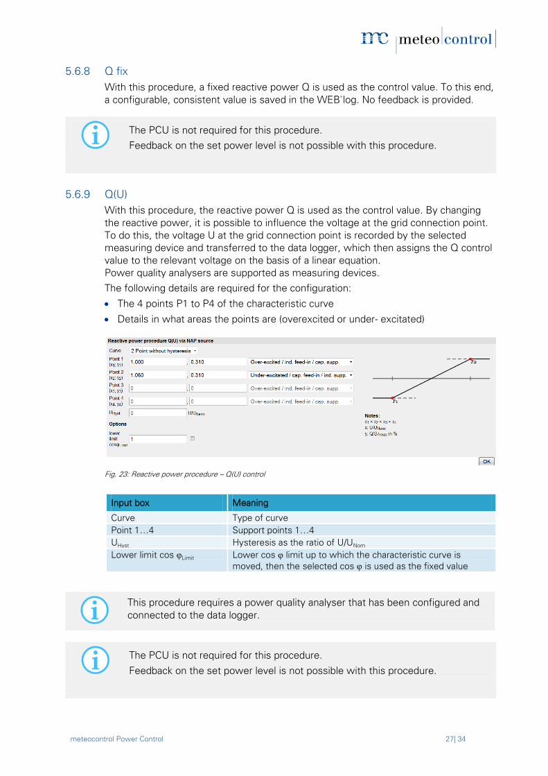
5.6.9 Q(U)
With this procedure, the reactive power Q is used as the control value. By changing
the reactive power, it is possible to influence the voltage at the grid connection point.
To do this, the voltage U at the grid connection point is recorded by the selected
measuring device and transferred to the data logger, which then assigns the Q control
value to the relevant voltage on the basis of a linear equation.
Power quality analysers are supported as measuring devices.
The following details are required for the configuration:
The 4 points P1 to P4 of the characteristic curve
Details in what areas the points are (overexcited or under- excitated)
Fig. 23: Reactive power procedure – Q(U) control
Input box Meaning
Curve Type of curve
Point 1…4 Support points 1…4
UHyst Hysteresis as the ratio of U/UNom
Lower limit cos φLimit Lower cos φ limit up to which the characteristic curve is
moved, then the selected cos φ is used as the fixed value
The PCU is not required for this procedure.
Feedback on the set power level is not possible with this procedure.
This procedure requires a power quality analyser that has been configured and
connected to the data logger.

28| 34 meteocontrol Power Control
5.6.10 Inverter cosφ (P)
This procedure is an inverter-internal procedure. The data logger has no influence over
control and allows the inverters to take over internal control. The power factor cosϕ is
used as the control value.
For the majority of inverters supporting this procedure, no settings need to be
made in the data logger. The parameters should be saved in the inverter itself.
For details of how to do this, please read the operating manual for the particular
inverter.
5.6.11 Inverter Q(U)
This procedure is an inverter internal procedure. The data logger has no influence over
control and allows the inverters to take over internal control. The reactive power Q is
used as the control value.
For the majority of inverters that support this procedure, no settings need to be
made in the data logger. The parameters should be saved in the inverter itself.
For details on the respective steps, please read the operating manual for the
inverter in use.

meteocontrol Power Control 29| 34
5.7 Enabling Power Control
Once all settings for meteocontrol Power Control have been made, Power Control
must be enabled. It is recommended to start Power Control only after the
configuration has been completed.
Fig. 24: Enabling Power Control
Input box Meaning
Power Control Enables or disables the PC
Save Saves the settings
5.8 Power Control status
Under Online Values > Power Control, you can bring up the current Power Control status.
Fig. 25: Power Control online values
Description Meaning
Operating status Current Power Control status
Active power procedure Displays the current active power procedure
Reactive power procedure Displays the current reactive power procedure
Current control value Control value requirement for active and reactive power
procedures in percent
The highlighted values are updated every 10 seconds. It is not possible to
configure these online values.

30| 34 meteocontrol Power Control
5.9 Power Control settings via the data logger display
The Power Control status can be queried and modified via the WEB’log PRO unlimited
display. Configuration of the meteocontrol Power Control on the other hand can only
be done via the web browser, as detailed in the previous chapters.
The WEB'log's user groups are password protected.
The standard passwords are:
User group "End customer" password "0030“
User group "Installer“ password "0020“
User group "Administrator“ password "0010“
Menu structure on the PRO unlimited display
Settings**
PC settings *** PC status enabled Power Control is active disabled Power Control is inactive
* User group “End customer”
** User group “Installer”
*** User group “Administrator”

meteocontrol Power Control 31| 34
6. Power quality analyser Because a power quality analyser (PQA) is a technical device with numerous functions,
a user-specific configuration is necessary.
It is recommended to install the transmitters at the grid connection point (support type
current transformer, voltage converter) in accordance with the generator meter arrow
system.
When selecting the components, the precision classes of at least 0.5 (fine
measurement device classes) should be ensured.
Furthermore, power and current converter must be selected in order to utilize the
measurement range of the power quality analyser to its fullest possible extent. To
control the active power, a single-phase measurement is considered sufficient.
However, a three-phase measurement is better recommended, as at the medium
voltage end the transformer usually has a triangular switching group, while the voltage
is measured against a star point.
To allow the use of Power Control, meteocontrol offers a suitable power quality
analyser (UMG604), which enables the measurements needed for a number of
procedures to be taken at the grid connection point.
Electrical installation of the PQA
The electrical planning and installation of PV systems, in particular the connection of
the power quality analyser at the grid connection point, are not covered by this manual.
However, the following steps for the use of the PQA must be observed:
PQA to GCP
The power quality analyser is connected to the grid connection point in accordance
with the relevant low voltage and/or medium voltage directives. Depending on the
system design, transmitters are required (support type current transformer, voltage
converter).
PQA to WEB`log
A power quality analyser (PQA) is always connected to the WEB’log configured as
the master via Modbus-RTU or Modbus-TCP. The device should be connected and
configured in accordance with the “Connecting Modbus devices" section of the
WEB’log operating manual.

32| 34 meteocontrol Power Control
7. Grid feed-in management overview
Supported WEB’logs Necessary accessories
Web’log Pro Unlimited
WEB‘log
Light+ 20
WEB‘log
Basic 100
WEB‘log Pro
Unlimited
Power quality
analyser (PQA)
PCU+
Active power procedure
P DI)
WEB`log
internal**
+ + +
P (DI) + +
P (AI) + +
P (fix) + + +
Inverter
internal
Driver-
dependent
Reactive power procedure
cosφ (DI) + +* +
cosφ (AI) + + +
cosφ (fix) + + + +*
cosφ (P) + +
cosφ (U) + +
Q (fix) + + + +*
Q (U) + + +
Inverter
internal
Driver-
dependent
Driver-
dependent
Driver-
dependent
* :
**:
PQA not necessary for systems connected to the low-voltage grid; PQA not
compatible with the Web’log Basic 100 and the Light+ 20
Connection of ripple control receiver to the internal digital inputs of the
WEB'log. For other procedures, connection is via the PCU.

meteocontrol Power Control 33| 34
8. List of figures Fig. 1: PCU<->Power Control functionality ................................................................... 8
Fig. 2: Power Control functionality ................................................................................ 9
Fig. 3: WEB`log master with broadcast to all slaves .................................................... 11
Fig. 4: WEB`log master without slaves ....................................................................... 11
Fig. 5: WEB`log master with slave groups .................................................................. 11
Fig. 6: WEB`log definition as slave – general broadcast .............................................. 12
Fig. 7: WEB`log definition as slave – group broadcast ................................................. 12
Fig. 8: Fallback defaults, example cosφ Fix ................................................................. 13
Fig. 9: Power control system data .............................................................................. 13
Fig. 10: Active power and reactive power procedures ................................................ 15
Fig. 11: GCP control loop configuration ....................................................................... 17
Fig. 12: Active power procedure – P(DI) control .......................................................... 18
Fig. 13: Active power procedure – P(AI) control .......................................................... 19
Fig. 14: Active power procedure – P(DI) internal ......................................................... 20
Fig. 15: Reactive power procedure – cosφ (DI) ............................................................ 21
Fig. 16: Example cosφ (AI) characteristic curve ........................................................... 22
Fig. 17: Reactive power procedure – cosφ (AI) control ................................................ 22
Fig. 18: Reactive power procedure – cosφ (P) control ................................................. 23
Fig. 19: Reactive power procedure – cosφ (U) control ................................................. 24
Fig. 20: Reactive power procedure – Q(DI) control ...................................................... 25
Fig. 21: Q(AI) characteristic curve ............................................................................... 26
Fig. 22: Reactive power procedure – Q(AI) control ...................................................... 26
Fig. 23: Reactive power procedure – Q(U) control....................................................... 27
Fig. 24: Enabling Power Control .................................................................................. 29
Fig. 25: Power Control online values ........................................................................... 29


Spicherer Str. 48 D-86157 Augsburg Phone +49 (0) 821 / 3 46 66-88 Fax +49 (0) 821 / 3 46 66-11 [email protected] www.meteocontrol.de
Text and illustrations represent state-of-the-art technology at the time of printing May be subject to technical
updates We assume no liability for printing errors.
Version 20131213